drawing checking procedure
DESCRIPTION
DCPTRANSCRIPT
ENGINEERING PROCEDURE – DRAWING CHECKING PROCEDURE
Page 2 of 14
TABLE OF CONTENTS
1.0 Purpose
2.0 Objectives
3.0 Scope
4.0 Compliance
5.0 General
6.0 Responsibilities
6.1 Senior Supervisor-Projects
6.2 Drawing Control Supervisor
6.3 Project Engineer
6.4 Draftsperson and Drawing Checker
7.0 Checking Practice
8.0 Checking Method
9.0 Drawing Print Checking Colours
10.0 Drawing Check List
ENGINEERING PROCEDURE – DRAWING CHECKING PROCEDURE
Page 3 of 14
1.0 Purpose
This procedure has been developed to provide a standardized and consistent approach in
checking for and correcting errors in AutoCAD and manual drawings for the
PETROJAM Ltd. Drawing Office.
2.0 Objectives
2.1 Ensure standardization of information, presentation and organization on drawings.
2.2 Deliver consistent drawing quality.
2.3 Minimize drawing errors and construction changes.
2.4 Promote ease of drawing interpretation and information understanding.
2.5 Ensure completeness of information to be conveyed.
3.0 Scope
This Procedure outlines standard practices to be adopted when checking and evaluating
completeness and accuracy of Project Drawings.
4.0 Compliance
All persons involved in checking Project Drawings shall adhere to this Procedure to
ensure that a uniform, complete and quality assured product will result. Compliance is
expected in all cases and any required deviation from this Procedure must receive prior
approval from Senior Supervisor-Projects.
5.0 General
This procedure is to be followed by all Engineering and Contract personnel directly
involved with Project Drawing development or checking.
6.0 Responsibilities
The positional responsibilities for the proper adherence to this Procedure on all
PETROJAM LIMITED projects are as follows.
ENGINEERING PROCEDURE – DRAWING CHECKING PROCEDURE
Page 4 of 14
6.1 Senior Projects Engineering Supervisor
6.1.1 Audit adherence to and compliance with this Procedure on all
PETROJAM Projects managed by the Technical Department/Projects
Group.
6.1.2 Evaluation of any non-compliance and implementation of required
corrective activities.
6.1.3 Review and update of this procedure every three (3) years.
6.1.4 Ensure understanding of this procedure by Strategic Planning personnel
directly involved with project development.
6.1.5 Review and approval of all Drawings.
6.2 Drawing Control Supervisor
6.2.1 Ensure adherence to and compliance with this Procedure on all projects
managed by the Technical Department/Projects Group.
6.2.2 Training of all Engineering personnel directly involved with project
development. All personnel are to be initially trained and retrained every
two (2) years.
6.2.3 Provide Drawing Checking assets and ensure all Drawings are properly
checked and corrected.
6.2.4 Assign checking responsibilities, ensure competence of Checker, ensure
proper information is provided to Checker and monitor progress of
checking.
6.2.5 Ensure proper storage and control of Drawing Check Prints.
6.2.6 Review and approval of all Drawings and initiation of approval routing.
6.2.7 Ensure proper Drawing storage, Archive & Back-up.
6.2.8 Ensure proper storage and control of all Project Documentation.
6.3 Project Engineer
6.3.1 Submission of Project Scope, all sketches, specifications and other
information required to complete requested Drawings and associated
documentation and allow proper Drawing Checking.
6.3.2 Directly work with Drawing Checker to facilitate his/her efforts.
6.3.3 Ensure effective presentation of all required information to facilitate
efficient construction. The Project Engineer is expected to directly work
ENGINEERING PROCEDURE – DRAWING CHECKING PROCEDURE
Page 5 of 14
with the Drawing Office during the development of all documentation and
timely provide direction and information.
6.3.4 Review and approval of all Drawings and associated documentation.
Ensure proper application and use of Design Standards, Material
Specifications and Equipment Specifications.
6.4 Draftsperson and Drawing Checker
6.4.1 Ensure understanding of this Procedure and all referenced Procedures and
compliance with these Procedures at all times.
6.4.2 Provide all services assigned by the Drawing Control Supervisor in an
efficient and expeditious manner. Ensure all information developed and
presented is accurate, complies with Standard Documentation, complies
with Design Standards and Material Specifications, can be efficiently
reviewed and used, and is practically error free. This will require
dedication to detail and diligence with emphasis on Quality and Added
Value.
6.4.3 Provide Check Prints, make corrections, retain marked Check Prints until
Project completion, provide final Drawings and signed Drawings.
7.0 Checking Practice
Project Drawings checking shall be completed by competent persons, as assigned by the
Drawing Office Supervisor, according to the following guidelines.
7.1 All project Drawings are to be checked for compliance with the Drawing Office
Procedures, clarity, standard structure, technical content, quality completeness
and adherence to design standards. Check prints are to be retained by the
Draftsperson until project completion and are subject to audit.
7.2 All AutoCAD Drawings are to be checked for compliance with the Drawing
Office Procedures and adherence to normal AutoCAD standards.
7.3 Drawing checking is not considered to be design checking although design is to
be considered at all times. Any questions concerning design shall be discussed
with and referred to the Project Engineer for h view and clarification.is/her re
ENGINEERING PROCEDURE – DRAWING CHECKING PROCEDURE
Page 6 of 14
7.4 Drawing checkers must be familiar with the requirements of the Drawing Office
Procedures, standard drafting Procedures, the project scope and concept, relevant
design standards and any additional information pertinent to the drawing to be
checked.
7.5 Drafting personnel will not be the last check of their own work prior to seeking
approvals.
7.6 When checking drawings, the checker and the draftsperson completing required
changes shall use the colour markings defined in section 9.0.
7.7 The Checker shall use the drawing check lists provided in section 10.0 to ensure
all pertinent factors are included and properly addressed. The checker shall use
his/her judgement to determine applicability and pertinence and shall draw from
the department expertise as required.
7.8 Manual checking of drawings shall be on bond paper Check Prints. A Check Print
shall be so designated by stencilling “Check Print” in large bold lettering above
the title block.
7.9 The checker shall use a “red” pencil to make all changes and comments, all
mark-up text shall be printed and the checker shall give emphasis to neatness,
clarity and conciseness.
7.10 The checker shall initial and date all comments and mark-ups requiring action and
those not so marked will be deemed to require no action.
7.11 Any errors in mark-ups shall be noted as such and lined through.
8.0 Checking Method
Each Project Drawing is to be checked frequently during development by those directly
involved with the work. Use of checking services does not diminish the responsibilities of
the draftsperson or Project Engineer for thorough, complete and quality work. As
ENGINEERING PROCEDURE – DRAWING CHECKING PROCEDURE
Page 7 of 14
drawing deficiencies are noted, they are to be corrected immediately and prior to
Drawing Checking.
8.1 The draftsperson shall be aware of the importance of quality work and shall check
his/her own work frequently during drawing development. The Project Engineer
shall work closely with the draftsperson and shall check each drawing at discreet
intermediate stages or at least weekly.
8.2 When a drawing is deemed complete by the draftsperson and Project Engineer,
the draftsperson shall produce a “check print” on bond paper and provide it to the
Drawing Office Supervisor for review.
8.3 The supervisor shall make a cursory review of the drawing for basic content,
structure and adherence to drafting standards. Any noted deficiencies shall be
corrected and a new check print produced.
8.4 The Drawing Office Supervisor shall designate a Drawing Checker and provide
him/her with the check print and all information required (scope, reference
drawings, project criteria, applicable specifications, etc.) to properly review the
drawing.
8.5 The checker is to thoroughly review all information on the drawing, ensure all
standards are met, mark all required changes and return the print to the
draftsperson.
8.6 The draftsperson is to review all mark-ups, clarify any questions and make the
required changes to the drawing, the marked up check print is to be retained for
future reference and a new check print shall be provided to the checker for any
additional changes or corrections.
8.7 When a drawing (AutoCAD) is deemed complete by the checker, as per review of
the check print, the Checker will check the digitized version of the drawing for
compliance with the Drawing Office Procedures and normal AutoCAD standards.
The draftsperson shall immediately correct any noted deficiencies.
8.8 After digital check, the drawing is to be printed on vellum, signed by the
Draftsperson and Checker and provided to the Drawing Office Supervisor.
ENGINEERING PROCEDURE – DRAWING CHECKING PROCEDURE
Page 8 of 14
8.9 The Drawing Office Supervisor shall initiate routing of the Drawing for approval
as per “General Drafting Practices”.
9.0 Drawing Print Checking Colours
Colours used for marking of check prints are to be as follows, with no exceptions.
Yellow Checked Ok (Checker or project engineer)
Red All corrections or mark-ups (Checker or project engineer)
Green Back-drafted (Draftsperson)
Blue Back-checked (Checker)
10.0 Drawing Check List
The drawing checker is expected to use the attached standard drawing check list to
facilitate his/her efforts. The list was developed to provide a guide or outline only and is
not intended to include all factors or cover all necessary issues. Documented evidence of
checking is by means of the checkers signature or initial (and date) on mark ups of the
check print so retention of the checklist is not required.
ENGINEERING PROCEDURE – DRAWING CHECKING PROCEDURE
Page 9 of 14
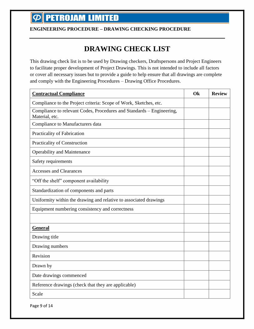
DRAWING CHECK LIST
This drawing check list is to be used by Drawing checkers, Draftspersons and Project Engineers
to facilitate proper development of Project Drawings. This is not intended to include all factors
or cover all necessary issues but to provide a guide to help ensure that all drawings are complete
and comply with the Engineering Procedures – Drawing Office Procedures.
Contractual Compliance Ok Review
Compliance to the Project criteria: Scope of Work, Sketches, etc.
Compliance to relevant Codes, Procedures and Standards – Engineering,
Material, etc.
Compliance to Manufacturers data
Practicality of Fabrication
Practicality of Construction
Operability and Maintenance
Safety requirements
Accesses and Clearances
“Off the shelf” component availability
Standardization of components and parts
Uniformity within the drawing and relative to associated drawings
Equipment numbering consistency and correctness
General
Drawing title
Drawing numbers
Revision
Drawn by
Date drawings commenced
Reference drawings (check that they are applicable)
Scale
ENGINEERING PROCEDURE – DRAWING CHECKING PROCEDURE
Page 10 of 14
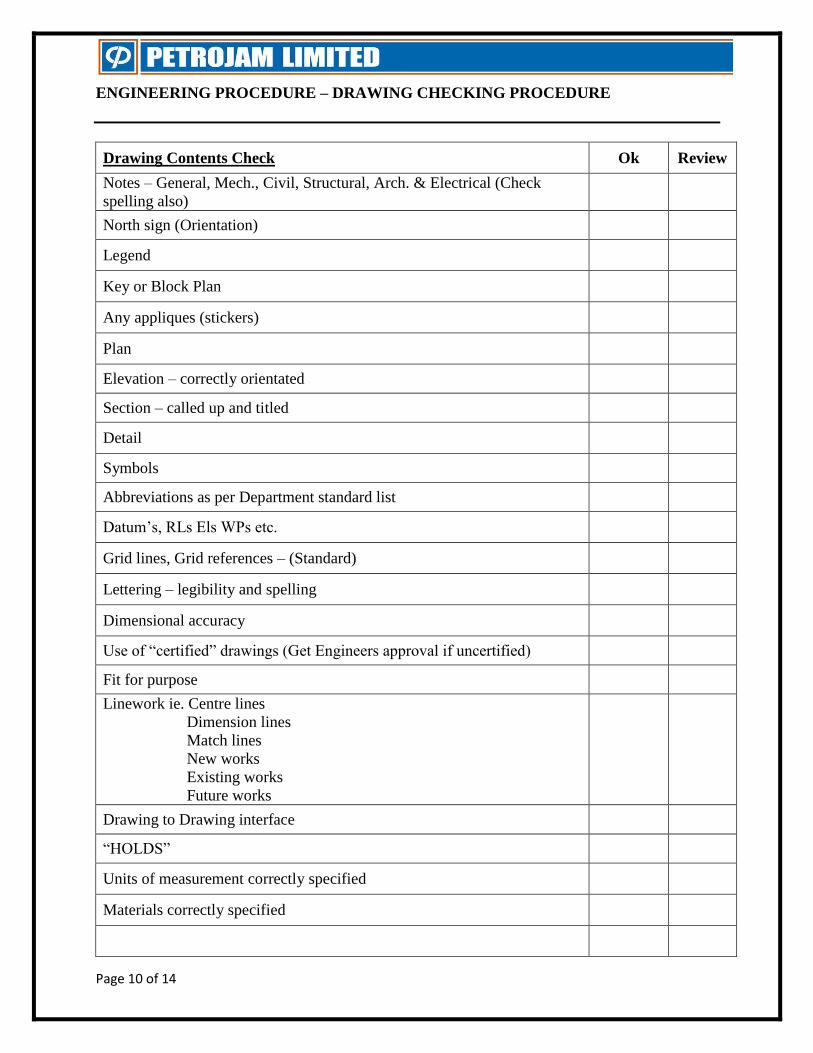
Drawing Contents Check Ok Review
Notes – General, Mech., Civil, Structural, Arch. & Electrical (Check
spelling also)
North sign (Orientation)
Legend
Key or Block Plan
Any appliques (stickers)
Plan
Elevation – correctly orientated
Section – called up and titled
Detail
Symbols
Abbreviations as per Department standard list
Datum’s, RLs Els WPs etc.
Grid lines, Grid references – (Standard)
Lettering – legibility and spelling
Dimensional accuracy
Use of “certified” drawings (Get Engineers approval if uncertified)
Fit for purpose
Linework ie. Centre lines
Dimension lines
Match lines
New works
Existing works
Future works
Drawing to Drawing interface
“HOLDS”
Units of measurement correctly specified
Materials correctly specified
ENGINEERING PROCEDURE – DRAWING CHECKING PROCEDURE
Page 11 of 14
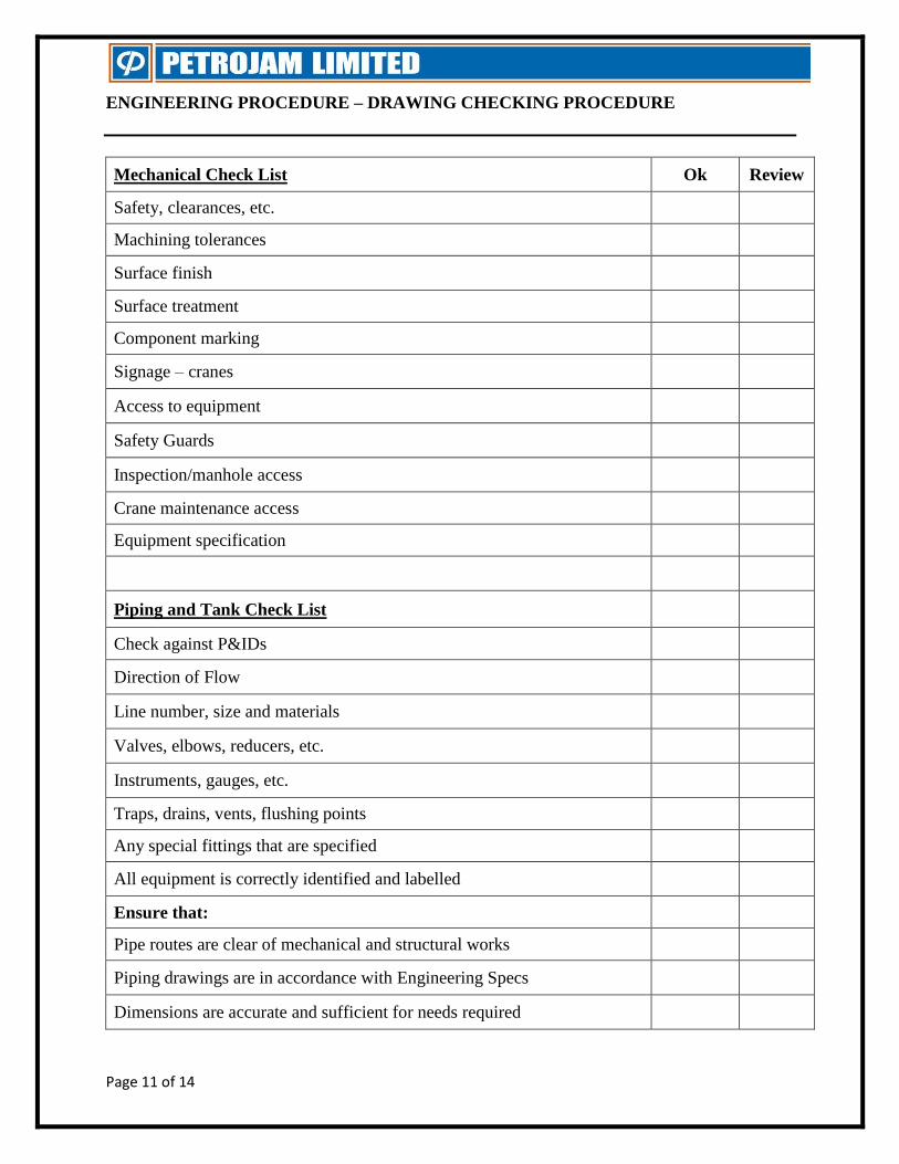
Mechanical Check List Ok Review
Safety, clearances, etc.
Machining tolerances
Surface finish
Surface treatment
Component marking
Signage – cranes
Access to equipment
Safety Guards
Inspection/manhole access
Crane maintenance access
Equipment specification
Piping and Tank Check List
Check against P&IDs
Direction of Flow
Line number, size and materials
Valves, elbows, reducers, etc.
Instruments, gauges, etc.
Traps, drains, vents, flushing points
Any special fittings that are specified
All equipment is correctly identified and labelled
Ensure that:
Pipe routes are clear of mechanical and structural works
Piping drawings are in accordance with Engineering Specs
Dimensions are accurate and sufficient for needs required
ENGINEERING PROCEDURE – DRAWING CHECKING PROCEDURE
Page 12 of 14
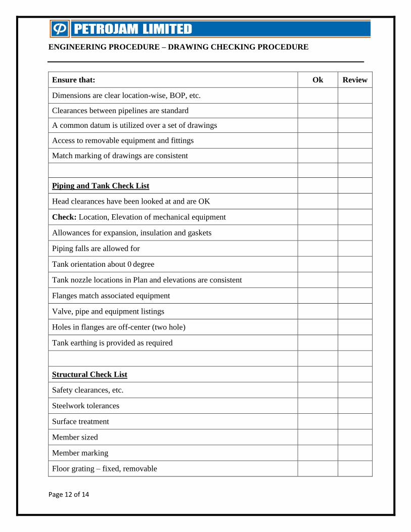
Ensure that: Ok Review
Dimensions are clear location-wise, BOP, etc.
Clearances between pipelines are standard
A common datum is utilized over a set of drawings
Access to removable equipment and fittings
Match marking of drawings are consistent
Piping and Tank Check List
Head clearances have been looked at and are OK
Check: Location, Elevation of mechanical equipment
Allowances for expansion, insulation and gaskets
Piping falls are allowed for
Tank orientation about 0 degree
Tank nozzle locations in Plan and elevations are consistent
Flanges match associated equipment
Valve, pipe and equipment listings
Holes in flanges are off-center (two hole)
Tank earthing is provided as required
Structural Check List
Safety clearances, etc.
Steelwork tolerances
Surface treatment
Member sized
Member marking
Floor grating – fixed, removable
ENGINEERING PROCEDURE – DRAWING CHECKING PROCEDURE
Page 13 of 14
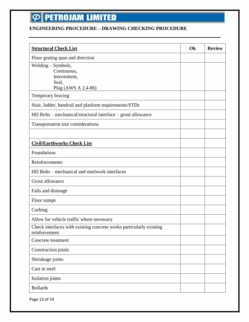
Structural Check List Ok Review
Floor grating span and direction
Welding – Symbols,
Continuous,
Intermittent,
Seal,
Plug (AWS A 2.4-86)
Temporary bracing
Stair, ladder, handrail and platform requirements/STDs
HD Bolts – mechanical/structural interface – grout allowance
Transportation size considerations
Civil/Earthworks Check List
Foundations
Reinforcements
HD Bolts – mechanical and steelwork interfaces
Grout allowance
Falls and drainage
Floor sumps
Curbing
Allow for vehicle traffic where necessary
Check interfaces with existing concrete works particularly existing
reinforcement
Concrete treatment
Construction joints
Shrinkage joints
Cast in steel
Isolation joints
Bollards
ENGINEERING PROCEDURE – DRAWING CHECKING PROCEDURE
Page 14 of 14
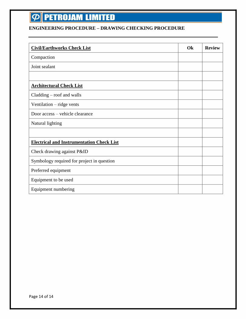
Civil/Earthworks Check List Ok Review
Compaction
Joint sealant
Architectural Check List
Cladding – roof and walls
Ventilation – ridge vents
Door access – vehicle clearance
Natural lighting
Electrical and Instrumentation Check List
Check drawing against P&ID
Symbology required for project in question
Preferred equipment
Equipment to be used
Equipment numbering