checking procedure general information this checking ...race.nangreaves.com/web/vx220/checking...
TRANSCRIPT
Checking Procedure General Information
This Checking Procedure contains the diagnosis of the following electronic system:
� Immobiliser
Vehicle Diagnostic Concept:
The main purpose of a vehicle diagnostic concept is locating and eliminating faults in the shortest time possible. Therefore, the following diagnostic strategy has been developed as a guideline that leads technicians straight to the source fault: Starting point is the vehicle that contains a certain number of electronic systems, e.g. engine management system, airbag, and ABS system. Each of these electronic systems consists of so - called "functional groups" that are functionally related to each other. A Coolant Temperature Sensor Circuit for example represents such a functional group. Each of the functional groups consists of several components, such as switches, sensors, wires etc. A Coolant Temperature Sensor Circuit for example is made up of a sensor, a wiring harness, a control unit, and the software of the control unit. Based on this structure, the first diagnostic step should be the identification and localisation of the defective electronic system, next comes the diagnosis of the corresponding defective functional group, and finally, locate and repair of the defective component within that group. The Diagnostic System Check (described in table A, Diagnostic System Check) of this checking procedure follows that diagnostic path. Diagnosis of an electronic system according to the above described concept always starts with this Main Check.
The instructions described in the Diagnostic System Check section must be followed closely. Every time a test or test step is passed without fault, the Diagnostic System Check continues with the next step. Some of the tests include references to related functional groups (tables B-x). When there is a fault, the corresponding functional group tests are performed in order to detect the defective functional group. When that group has been identified, the troubleshooting tables (C-x) are used to locate the faulty component. After repair of the fault, the affected functional group (tables B-x) must be rechecked to continue after this test at the appropriate position of the Diagnostic System Check (table A). When all test steps of the Diagnostic System Check have been completed successfully, the system is fully operational.
Safety Measures
Page 1 of 63
12/25/2005file://C:\Program%20Files\cosids\DATA\TMP\TmpPrn359232138.HTM
Please take notice of any relevant safety measures for each work operation / step.
The safety measures can be found in the following area of TIS 2000:
� Service Information � Standard Information � Select: Model � Select: Model year � Select: One or more assembly groups � Application: Warnings, disclaimers, safety
Electronic System Specific Information
� Trouble Code Features In a few cases, the diagnostic tester may display a trouble code status or description that looks unfamiliar: Trouble Code Status: Instead of the known PRESENT, NOT PRESENT (and INTERMITTENT) message, you may read UNKNOWN DTC in the tester display. This tells you that the diagnostic software or control unit contains a piece of incorrect information that is unknown to the diagnostic tester and that it is unable to read or evaluate. Both the trouble code number and the trouble code text are not changed in this case. The above mentioned special cases can not be removed by means of a diagnostic tester function.
� Datalist Parameter Depending on the vehicle/system configuration it is possible that some datalist parameters or test steps, although they are listed in this checking procedure, are not shown on the diagnostic tester display. In that case, these datalist parameters are not valid for this vehicle/system configuration.
� Immobiliser and Anti-Theft Warning System installed Though there is a programming function "Programming Immobiliser Output" available, it is necessary to program the immobiliser always as with "No Anti-Theft Warning System". For this particular model, the functionality of the immobiliser to send a disarming signal to the anti-theft warning system has been omitted. On this basis the immobiliser has to be always programmed with ''No Anti-Theft Warning System'. If programming is performed faulty, PRESENT trouble codes will be set, which can not be erased. The immobiliser should be programmed with "No Anti-Theft Warning System" to erase the trouble codes with status PRESENT.
Electronic System Picture Information Block Diagram (Model Year '01-'02 )
Page 2 of 63
12/25/2005file://C:\Program%20Files\cosids\DATA\TMP\TmpPrn359232138.HTM

Legend Legend
15 Ignition ON (terminal 15 ) A4 Control Unit - Multec
30 System voltage (terminal 30 ) A17 Control Unit - Immobiliser
31 Ground (terminal 31 ) X13 Diagnostic Link
Abbreviations:
I = Transponder-Key
Control Unit/Component Survey
Page 3 of 63
12/25/2005file://C:\Program%20Files\cosids\DATA\TMP\TmpPrn359232138.HTM

No. Legend No. Legend
1 A17 Control Unit - Immobiliser
4 Ignition Lock
2 Transponder Car Key 5
Aerial
(integrated component in control unit immobiliser)
3 Transponder
Parts Location
Page 4 of 63
12/25/2005file://C:\Program%20Files\cosids\DATA\TMP\TmpPrn359232138.HTM
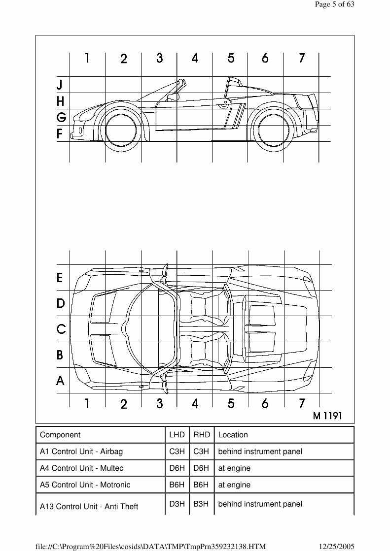
Component LHD RHD Location
A1 Control Unit - Airbag C3H C3H behind instrument panel
A4 Control Unit - Multec D6H D6H at engine
A5 Control Unit - Motronic B6H B6H at engine
A13 Control Unit - Anti Theft D3H B3H behind instrument panel
Page 5 of 63
12/25/2005file://C:\Program%20Files\cosids\DATA\TMP\TmpPrn359232138.HTM
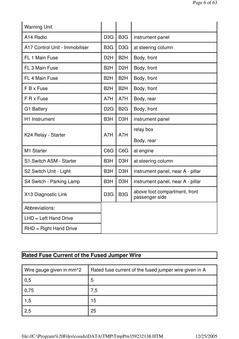
Warning Unit
A14 Radio D3G B3G instrument panel
A17 Control Unit - Immobiliser B3G D3G at steering column
FL 1 Main Fuse D2H B2H Body, front
FL 3 Main Fuse B2H D2H Body, front
FL 4 Main Fuse B2H B2H Body, front
F B x Fuse B2H B2H Body, front
F R x Fuse A7H A7H Body, rear
G1 Battery D2G B2G Body, front
H1 Instrument B3H D3H instrument panel
K24 Relay - Starter A7H A7H relay box
Body, rear
M1 Starter C6G C6G at engine
S1 Switch ASM - Starter B3H D3H at steering column
S2 Switch Unit - Light B3H D3H instrument panel, near A - pillar
S4 Switch - Parking Lamp B3H D3H instrument panel, near A - pillar
X13 Diagnostic Link D3G B3G above foot compartment, front passenger side
Abbreviations:
LHD = Left Hand Drive
RHD = Right Hand Drive
Rated Fuse Current of the Fused Jumper Wire
Wire gauge given in mm^2 Rated fuse current of the fused jumper wire given in A
0,5 5
0,75 7,5
1,5 15
2,5 25
Page 6 of 63
12/25/2005file://C:\Program%20Files\cosids\DATA\TMP\TmpPrn359232138.HTM
Note:
When troubleshooting is performed with a fused jumper wire (checking for short to ground/voltage) an automatic fuse can be used instead of the fuse wire, provided that the fuse current rating is identical.
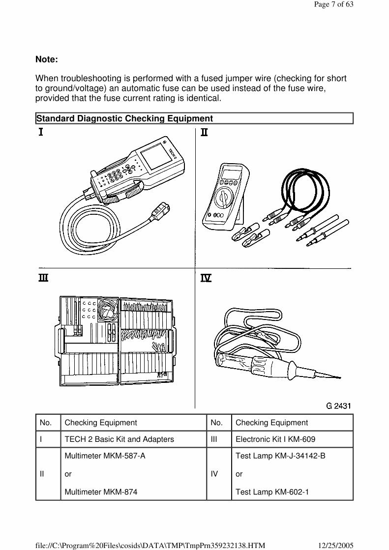
Standard Diagnostic Checking Equipment
No. Checking Equipment No. Checking Equipment
I TECH 2 Basic Kit and Adapters III Electronic Kit I KM-609
II
Multimeter MKM-587-A
or
Multimeter MKM-874
IV
Test Lamp KM-J-34142-B
or
Test Lamp KM-602-1
Page 7 of 63
12/25/2005file://C:\Program%20Files\cosids\DATA\TMP\TmpPrn359232138.HTM
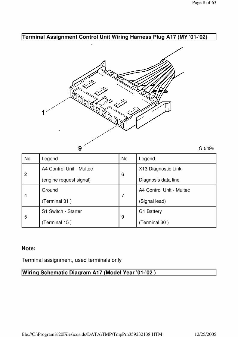
Note:
Terminal assignment, used terminals only
Terminal Assignment Control Unit Wiring Harness Plug A17 (MY '01-'02)
No. Legend No. Legend
2 A4 Control Unit - Multec
(engine request signal) 6
X13 Diagnostic Link
Diagnosis data line
4 Ground
(Terminal 31 ) 7
A4 Control Unit - Multec
(Signal lead)
5 S1 Switch - Starter
(Terminal 15 ) 9
G1 Battery
(Terminal 30 )
Wiring Schematic Diagram A17 (Model Year '01-'02 )
Page 8 of 63
12/25/2005file://C:\Program%20Files\cosids\DATA\TMP\TmpPrn359232138.HTM
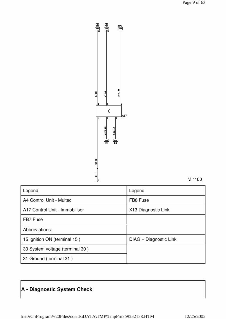
Legend Legend
A4 Control Unit - Multec FB8 Fuse
A17 Control Unit - Immobiliser X13 Diagnostic Link
FB7 Fuse
Abbreviations:
15 Ignition ON (terminal 15 ) DIAG = Diagnostic Link
30 System voltage (terminal 30 )
31 Ground (terminal 31 )
A - Diagnostic System Check
Page 9 of 63
12/25/2005file://C:\Program%20Files\cosids\DATA\TMP\TmpPrn359232138.HTM
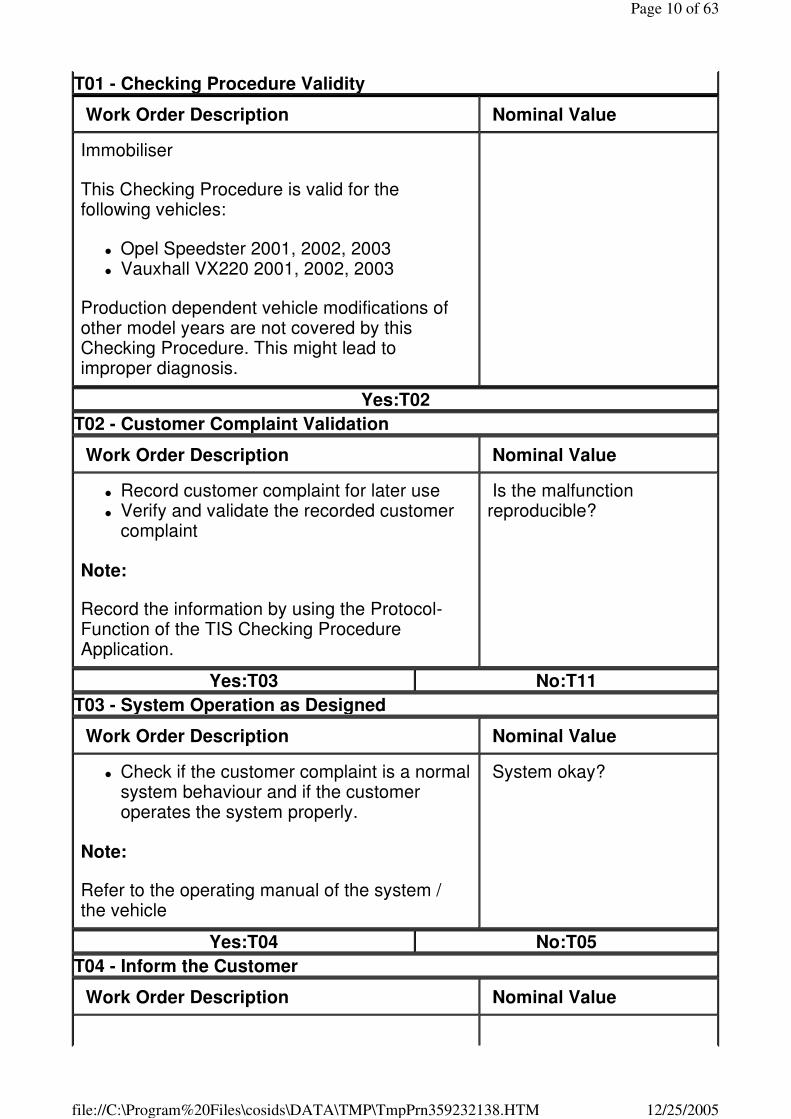
T01 - Checking Procedure Validity
Work Order Description Nominal Value
Immobiliser
This Checking Procedure is valid for the following vehicles:
� Opel Speedster 2001, 2002, 2003 � Vauxhall VX220 2001, 2002, 2003
Production dependent vehicle modifications of other model years are not covered by this Checking Procedure. This might lead to improper diagnosis.
Yes:T02
T02 - Customer Complaint Validation
Work Order Description Nominal Value
� Record customer complaint for later use � Verify and validate the recorded customer
complaint
Note:
Record the information by using the Protocol-Function of the TIS Checking Procedure Application.
Is the malfunction reproducible?
Yes:T03 No:T11
T03 - System Operation as Designed
Work Order Description Nominal Value
� Check if the customer complaint is a normal system behaviour and if the customer operates the system properly.
Note:
Refer to the operating manual of the system / the vehicle
System okay?
Yes:T04 No:T05
T04 - Inform the Customer
Work Order Description Nominal Value
Page 10 of 63
12/25/2005file://C:\Program%20Files\cosids\DATA\TMP\TmpPrn359232138.HTM
� Inform the customer, that the system behaviour is normal respectively how to operate the system correctly.
Yes:
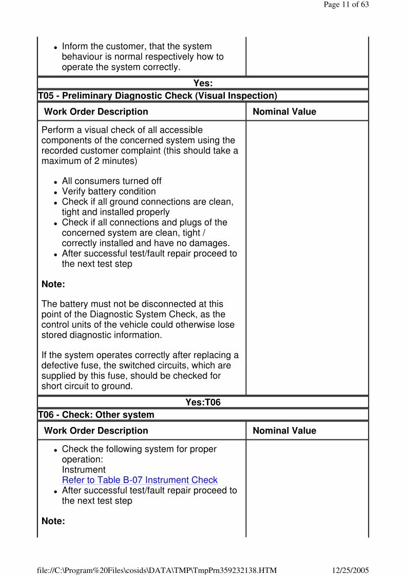
T05 - Preliminary Diagnostic Check (Visual Inspection)
Work Order Description Nominal Value
Perform a visual check of all accessible components of the concerned system using the recorded customer complaint (this should take a maximum of 2 minutes)
� All consumers turned off � Verify battery condition � Check if all ground connections are clean,
tight and installed properly � Check if all connections and plugs of the
concerned system are clean, tight / correctly installed and have no damages.
� After successful test/fault repair proceed to the next test step
Note:
The battery must not be disconnected at this point of the Diagnostic System Check, as the control units of the vehicle could otherwise lose stored diagnostic information.
If the system operates correctly after replacing a defective fuse, the switched circuits, which are supplied by this fuse, should be checked for short circuit to ground.
Yes:T06
T06 - Check: Other system
Work Order Description Nominal Value
� Check the following system for proper operation: Instrument Refer to Table B-07 Instrument Check
� After successful test/fault repair proceed to the next test step
Note:
Page 11 of 63
12/25/2005file://C:\Program%20Files\cosids\DATA\TMP\TmpPrn359232138.HTM
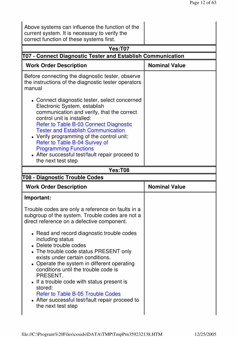
Above systems can influence the function of the current system. It is necessary to verify the correct function of these systems first.
Yes:T07
T07 - Connect Diagnostic Tester and Establish Communication
Work Order Description Nominal Value
Before connecting the diagnostic tester, observe the instructions of the diagnostic tester operators manual
� Connect diagnostic tester, select concerned Electronic System, establish communication and verify, that the correct control unit is installed: Refer to Table B-03 Connect Diagnostic Tester and Establish Communication
� Verify programming of the control unit: Refer to Table B-04 Survey of Programming Functions
� After successful test/fault repair proceed to the next test step
Yes:T08
T08 - Diagnostic Trouble Codes
Work Order Description Nominal Value
Important:
Trouble codes are only a reference on faults in a subgroup of the system. Trouble codes are not a direct reference on a defective component.
� Read and record diagnostic trouble codes including status
� Delete trouble codes � The trouble code status PRESENT only
exists under certain conditions. � Operate the system in different operating
conditions until the trouble code is PRESENT.
� If a trouble code with status present is stored: Refer to Table B-05 Trouble Codes
� After successful test/fault repair proceed to the next test step
Page 12 of 63
12/25/2005file://C:\Program%20Files\cosids\DATA\TMP\TmpPrn359232138.HTM
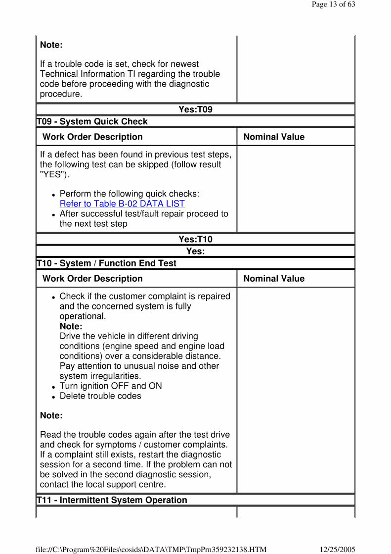
Note:
If a trouble code is set, check for newest Technical Information TI regarding the trouble code before proceeding with the diagnostic procedure.
Yes:T09
T09 - System Quick Check
Work Order Description Nominal Value
If a defect has been found in previous test steps, the following test can be skipped (follow result "YES").
� Perform the following quick checks: Refer to Table B-02 DATA LIST
� After successful test/fault repair proceed to the next test step
Yes:T10
Yes:
T10 - System / Function End Test
Work Order Description Nominal Value
� Check if the customer complaint is repaired and the concerned system is fully operational. Note: Drive the vehicle in different driving conditions (engine speed and engine load conditions) over a considerable distance. Pay attention to unusual noise and other system irregularities.
� Turn ignition OFF and ON � Delete trouble codes
Note:
Read the trouble codes again after the test drive and check for symptoms / customer complaints. If a complaint still exists, restart the diagnostic session for a second time. If the problem can not be solved in the second diagnostic session, contact the local support centre.
T11 - Intermittent System Operation
Page 13 of 63
12/25/2005file://C:\Program%20Files\cosids\DATA\TMP\TmpPrn359232138.HTM

Work Order Description Nominal Value
Most intermittent problems are caused by faulty electrical connectors, faulty ground connections, broken wiring, temperature problems or radio interference.
Intermittent faults can be traced either by using INTERMITTENT/NOT PRESENT trouble codes or the snapshot function of the diagnostic tester in combination with the following tests:
� Perform the following evaluation: Refer to Table B-10 Check: Intermittent Faults
� After successful test/fault repair proceed to the next test step
Yes:T10
B-01 - DIAGNOSTIC TROUBLE CODE B1000 - Replace Electronic Control Unit (ECU)
� Control unit hardware failure (EPROM, EEPROM, RAM, ROM defective)
Concerned Terminals: -
Refer to test step :C-02
B3040 - Communication Malfunction on W-line
� During communication between engine and immobiliser control unit transmission was interrupted.
Concerned Terminals: 7
Refer to test step :C-05
B3042 - Communication Line W Voltage Low
� Short to ground in circuit to control unit terminal 7 � Above condition must be fulfilled for at least 3 s .
Concerned Terminals: 7
Refer to test step :C-05
B3043 - Communication Line W Voltage High
� Short to voltage in circuit to control unit terminal 7
Concerned Terminals: 7
Page 14 of 63
12/25/2005file://C:\Program%20Files\cosids\DATA\TMP\TmpPrn359232138.HTM
Refer to test step :C-05
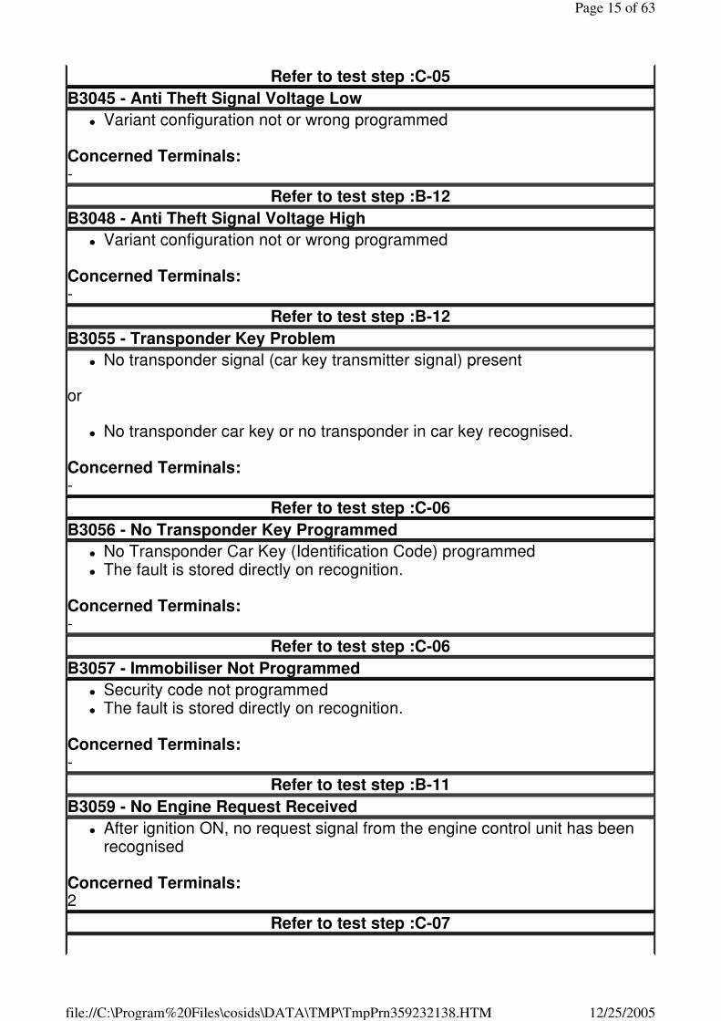
B3045 - Anti Theft Signal Voltage Low
� Variant configuration not or wrong programmed
Concerned Terminals: -
Refer to test step :B-12
B3048 - Anti Theft Signal Voltage High
� Variant configuration not or wrong programmed
Concerned Terminals: -
Refer to test step :B-12
B3055 - Transponder Key Problem
� No transponder signal (car key transmitter signal) present
or
� No transponder car key or no transponder in car key recognised.
Concerned Terminals: -
Refer to test step :C-06
B3056 - No Transponder Key Programmed
� No Transponder Car Key (Identification Code) programmed � The fault is stored directly on recognition.
Concerned Terminals: -
Refer to test step :C-06
B3057 - Immobiliser Not Programmed
� Security code not programmed � The fault is stored directly on recognition.
Concerned Terminals: -
Refer to test step :B-11
B3059 - No Engine Request Received
� After ignition ON, no request signal from the engine control unit has been recognised
Concerned Terminals: 2
Refer to test step :C-07
Page 15 of 63
12/25/2005file://C:\Program%20Files\cosids\DATA\TMP\TmpPrn359232138.HTM
B3060 - Unknown Transponder Key
� Transponder signal (Car Key Transmitter) recognition fault
or
� Transponder car key (identification code) not recognised.
Concerned Terminals: -
Refer to test step :C-06
B3061 - Wrong Transponder Key
� No secret code correspondence of transponder car key and engine control unit recognised.
Concerned Terminals: -
Refer to test step :C-06
B3077 - Wrong Transponder Type detected
� Type of transponder car key not recognised.
Concerned Terminals: -
Refer to test step :C-06
B-02 - DATA LIST T01 - Tester Display Ignition Status
Work Order Description Nominal Value
� Ignition OFF Off 0V
� Ignition ON On 12V
Concerned Terminals: 5
Yes:T02 No:C-04
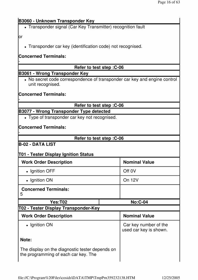
T02 - Tester Display Transponder-Key
Work Order Description Nominal Value
� Ignition ON
Note:
The display on the diagnostic tester depends on the programming of each car key. The
Car key number of the used car key is shown.
Page 16 of 63
12/25/2005file://C:\Program%20Files\cosids\DATA\TMP\TmpPrn359232138.HTM
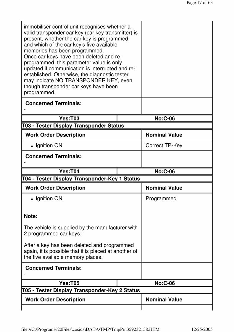
immobiliser control unit recognises whether a valid transponder car key (car key transmitter) is present, whether the car key is programmed, and which of the car key's five available memories has been programmed. Once car keys have been deleted and re-programmed, this parameter value is only updated if communication is interrupted and re-established. Otherwise, the diagnostic tester may indicate NO TRANSPONDER KEY, even though transponder car keys have been programmed.
Concerned Terminals: -
Yes:T03 No:C-06
T03 - Tester Display Transponder Status
Work Order Description Nominal Value
� Ignition ON Correct TP-Key
Concerned Terminals: -
Yes:T04 No:C-06
T04 - Tester Display Transponder-Key 1 Status
Work Order Description Nominal Value
� Ignition ON
Note:
The vehicle is supplied by the manufacturer with 2 programmed car keys.
After a key has been deleted and programmed again, it is possible that it is placed at another of the five available memory places.
Programmed
Concerned Terminals: -
Yes:T05 No:C-06
T05 - Tester Display Transponder-Key 2 Status
Work Order Description Nominal Value
Page 17 of 63
12/25/2005file://C:\Program%20Files\cosids\DATA\TMP\TmpPrn359232138.HTM
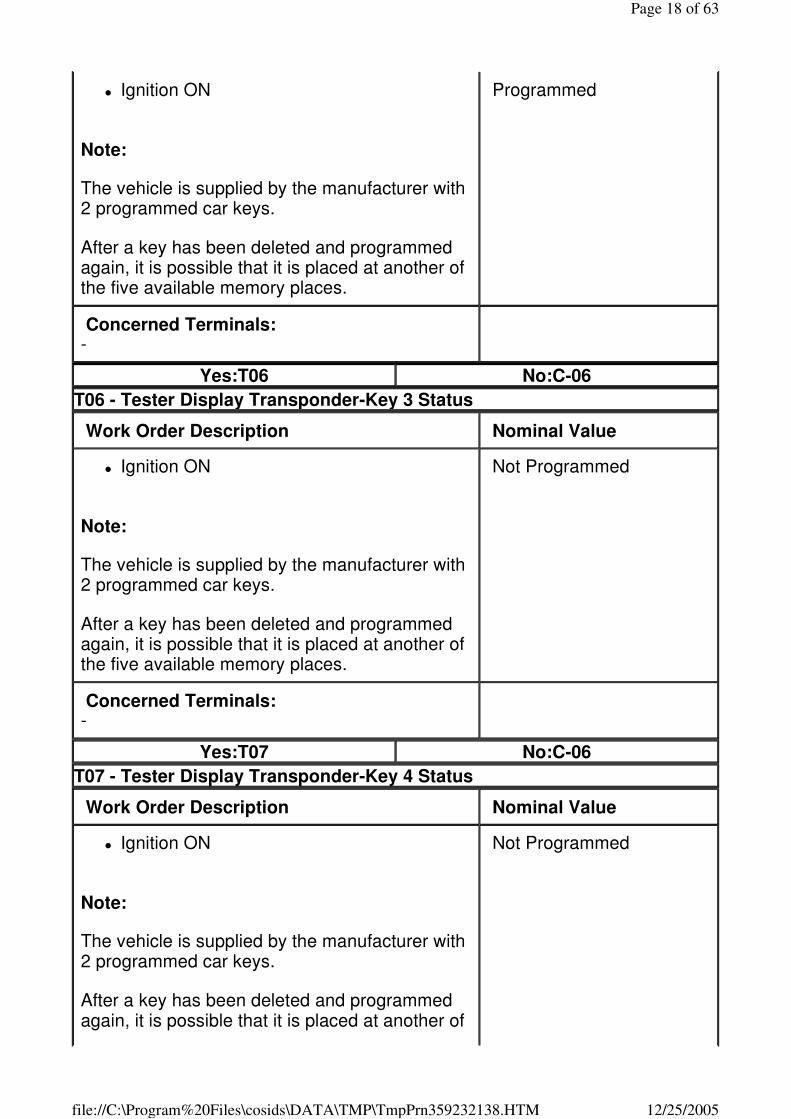
� Ignition ON
Note:
The vehicle is supplied by the manufacturer with 2 programmed car keys.
After a key has been deleted and programmed again, it is possible that it is placed at another of the five available memory places.
Programmed
Concerned Terminals: -
Yes:T06 No:C-06
T06 - Tester Display Transponder-Key 3 Status
Work Order Description Nominal Value
� Ignition ON
Note:
The vehicle is supplied by the manufacturer with 2 programmed car keys.
After a key has been deleted and programmed again, it is possible that it is placed at another of the five available memory places.
Not Programmed
Concerned Terminals: -
Yes:T07 No:C-06
T07 - Tester Display Transponder-Key 4 Status
Work Order Description Nominal Value
� Ignition ON
Note:
The vehicle is supplied by the manufacturer with 2 programmed car keys.
After a key has been deleted and programmed again, it is possible that it is placed at another of
Not Programmed
Page 18 of 63
12/25/2005file://C:\Program%20Files\cosids\DATA\TMP\TmpPrn359232138.HTM
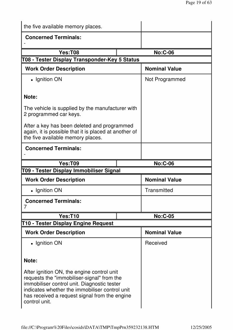
the five available memory places.
Concerned Terminals: -
Yes:T08 No:C-06
T08 - Tester Display Transponder-Key 5 Status
Work Order Description Nominal Value
� Ignition ON
Note:
The vehicle is supplied by the manufacturer with 2 programmed car keys.
After a key has been deleted and programmed again, it is possible that it is placed at another of the five available memory places.
Not Programmed
Concerned Terminals: -
Yes:T09 No:C-06
T09 - Tester Display Immobiliser Signal
Work Order Description Nominal Value
� Ignition ON Transmitted
Concerned Terminals: 7
Yes:T10 No:C-05
T10 - Tester Display Engine Request
Work Order Description Nominal Value
� Ignition ON
Note:
After ignition ON, the engine control unit requests the "immobiliser-signal" from the immobiliser control unit. Diagnostic tester indicates whether the immobiliser control unit has received a request signal from the engine control unit.
Received
Page 19 of 63
12/25/2005file://C:\Program%20Files\cosids\DATA\TMP\TmpPrn359232138.HTM
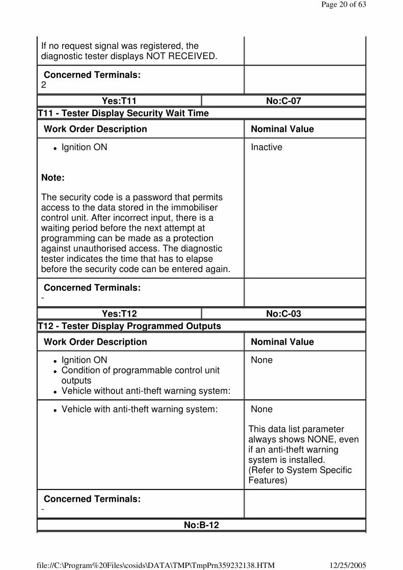
If no request signal was registered, the diagnostic tester displays NOT RECEIVED.
Concerned Terminals: 2
Yes:T11 No:C-07
T11 - Tester Display Security Wait Time
Work Order Description Nominal Value
� Ignition ON
Note:
The security code is a password that permits access to the data stored in the immobiliser control unit. After incorrect input, there is a waiting period before the next attempt at programming can be made as a protection against unauthorised access. The diagnostic tester indicates the time that has to elapse before the security code can be entered again.
Inactive
Concerned Terminals: -
Yes:T12 No:C-03
T12 - Tester Display Programmed Outputs
Work Order Description Nominal Value
� Ignition ON � Condition of programmable control unit
outputs � Vehicle without anti-theft warning system:
None
� Vehicle with anti-theft warning system: None
This data list parameter always shows NONE, even if an anti-theft warning system is installed. (Refer to System Specific Features)
Concerned Terminals: -
No:B-12
Page 20 of 63
12/25/2005file://C:\Program%20Files\cosids\DATA\TMP\TmpPrn359232138.HTM

B-03 - Connect Diagnostic Tester and Establish Communication T01 - Connect Diagnostic Tester
Work Order Description Nominal Value
Before connecting the diagnostic tester, observe the instructions of the diagnostic tester operators manual
-
Connect diagnostic tester:
� Ignition OFF � Connect the diagnostic tester with the
required adapter to the diagnostic link � Ignition ON � Engine OFF
Select concerned electronic system and establish communication:
� Select diagnostics � Select model year:
2001 (2001)2002 (2002)2003 (2003) � Select model:
Speedster/VX220 � Select electronic system group:
Electronic body system � Select electronic system or engine:
Immobiliser � Diagnostic tester now establishes
communication with the selected Electronic System.
Communication established and selected system recognised?
Yes: No:T02
T02 - Check: Fault Location
Work Order Description Nominal Value
� Communication with control unit is interrupted
� Does one of the following messages appear on the Diagnostic Tester display? Selected System Existing ECU Mismatch! or Mismatch between selected engine and existing engine ECU!
Page 21 of 63
12/25/2005file://C:\Program%20Files\cosids\DATA\TMP\TmpPrn359232138.HTM
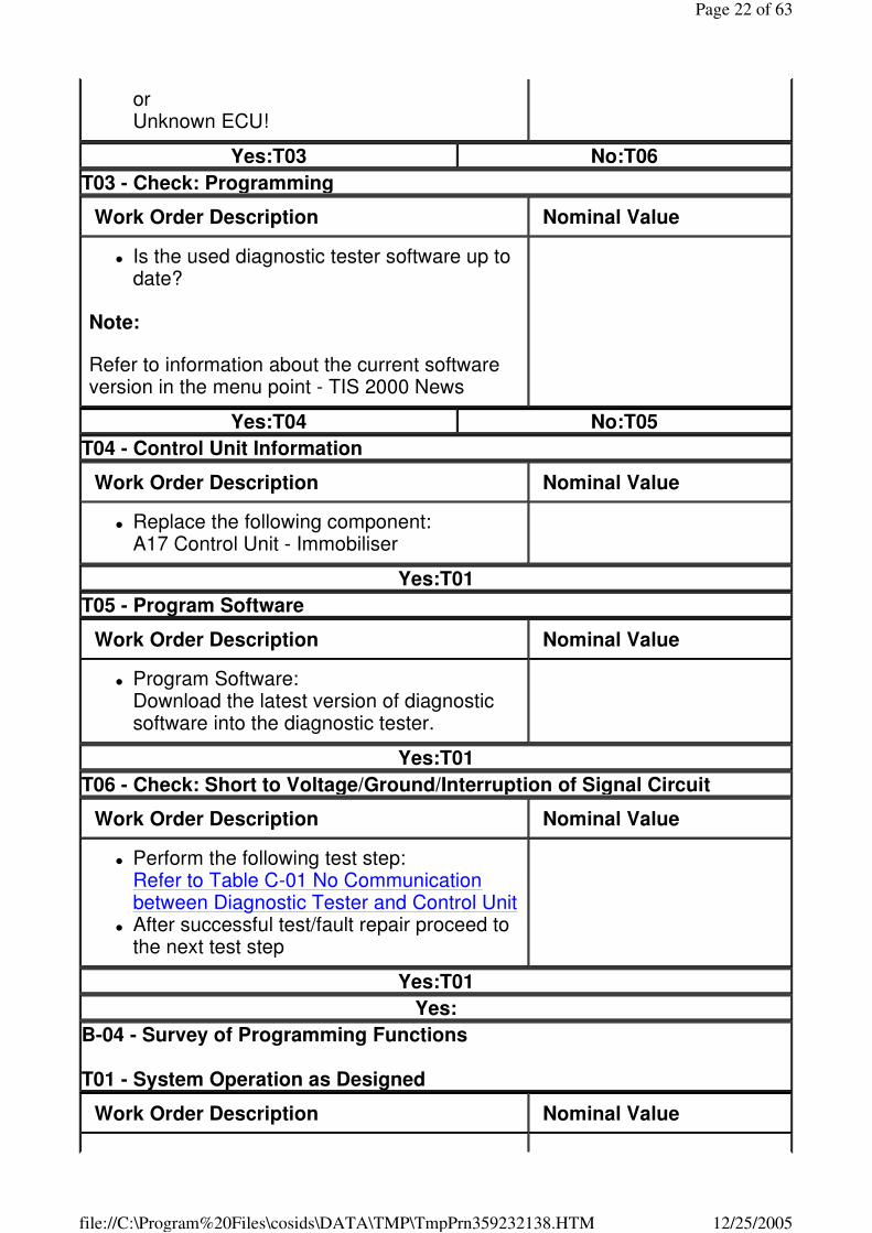
or Unknown ECU!
Yes:T03 No:T06
T03 - Check: Programming
Work Order Description Nominal Value
� Is the used diagnostic tester software up to date?
Note:
Refer to information about the current software version in the menu point - TIS 2000 News
Yes:T04 No:T05
T04 - Control Unit Information
Work Order Description Nominal Value
� Replace the following component: A17 Control Unit - Immobiliser
Yes:T01
T05 - Program Software
Work Order Description Nominal Value
� Program Software: Download the latest version of diagnostic software into the diagnostic tester.
Yes:T01
T06 - Check: Short to Voltage/Ground/Interruption of Signal Circuit
Work Order Description Nominal Value
� Perform the following test step: Refer to Table C-01 No Communication between Diagnostic Tester and Control Unit
� After successful test/fault repair proceed to the next test step
Yes:T01
Yes:
B-04 - Survey of Programming Functions T01 - System Operation as Designed
Work Order Description Nominal Value
Page 22 of 63
12/25/2005file://C:\Program%20Files\cosids\DATA\TMP\TmpPrn359232138.HTM
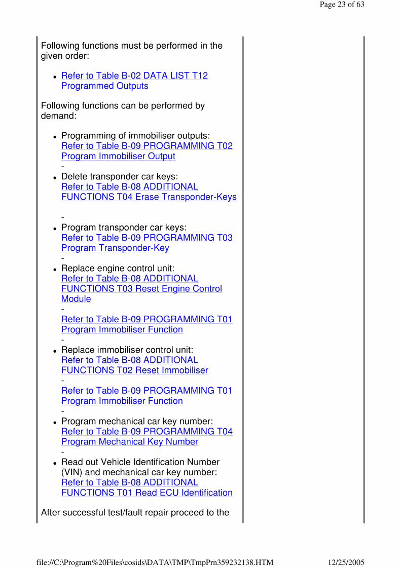
Following functions must be performed in the given order:
� Refer to Table B-02 DATA LIST T12 Programmed Outputs
Following functions can be performed by demand:
� Programming of immobiliser outputs: Refer to Table B-09 PROGRAMMING T02 Program Immobiliser Output -
� Delete transponder car keys: Refer to Table B-08 ADDITIONAL FUNCTIONS T04 Erase Transponder-Keys -
� Program transponder car keys: Refer to Table B-09 PROGRAMMING T03 Program Transponder-Key -
� Replace engine control unit: Refer to Table B-08 ADDITIONAL FUNCTIONS T03 Reset Engine Control Module - Refer to Table B-09 PROGRAMMING T01 Program Immobiliser Function -
� Replace immobiliser control unit: Refer to Table B-08 ADDITIONAL FUNCTIONS T02 Reset Immobiliser - Refer to Table B-09 PROGRAMMING T01 Program Immobiliser Function -
� Program mechanical car key number: Refer to Table B-09 PROGRAMMING T04 Program Mechanical Key Number -
� Read out Vehicle Identification Number (VIN) and mechanical car key number: Refer to Table B-08 ADDITIONAL FUNCTIONS T01 Read ECU Identification
After successful test/fault repair proceed to the
Page 23 of 63
12/25/2005file://C:\Program%20Files\cosids\DATA\TMP\TmpPrn359232138.HTM
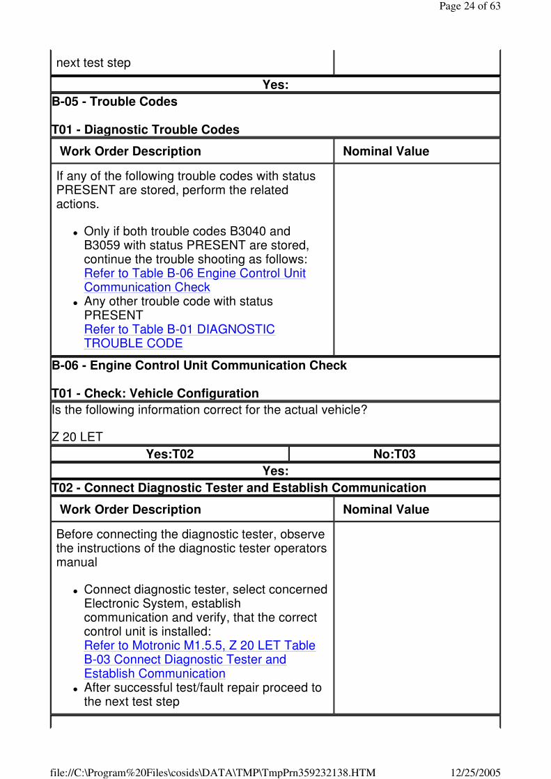
next test step
Yes:
B-05 - Trouble Codes T01 - Diagnostic Trouble Codes
Work Order Description Nominal Value
If any of the following trouble codes with status PRESENT are stored, perform the related actions.
� Only if both trouble codes B3040 and B3059 with status PRESENT are stored, continue the trouble shooting as follows: Refer to Table B-06 Engine Control Unit Communication Check
� Any other trouble code with status PRESENT Refer to Table B-01 DIAGNOSTIC TROUBLE CODE
B-06 - Engine Control Unit Communication Check T01 - Check: Vehicle Configuration
Is the following information correct for the actual vehicle?
Z 20 LET
Yes:T02 No:T03
Yes:
T02 - Connect Diagnostic Tester and Establish Communication
Work Order Description Nominal Value
Before connecting the diagnostic tester, observe the instructions of the diagnostic tester operators manual
� Connect diagnostic tester, select concerned Electronic System, establish communication and verify, that the correct control unit is installed: Refer to Motronic M1.5.5, Z 20 LET Table B-03 Connect Diagnostic Tester and Establish Communication
� After successful test/fault repair proceed to the next test step
Page 24 of 63
12/25/2005file://C:\Program%20Files\cosids\DATA\TMP\TmpPrn359232138.HTM
Yes:
T03 - Connect Diagnostic Tester and Establish Communication
Work Order Description Nominal Value
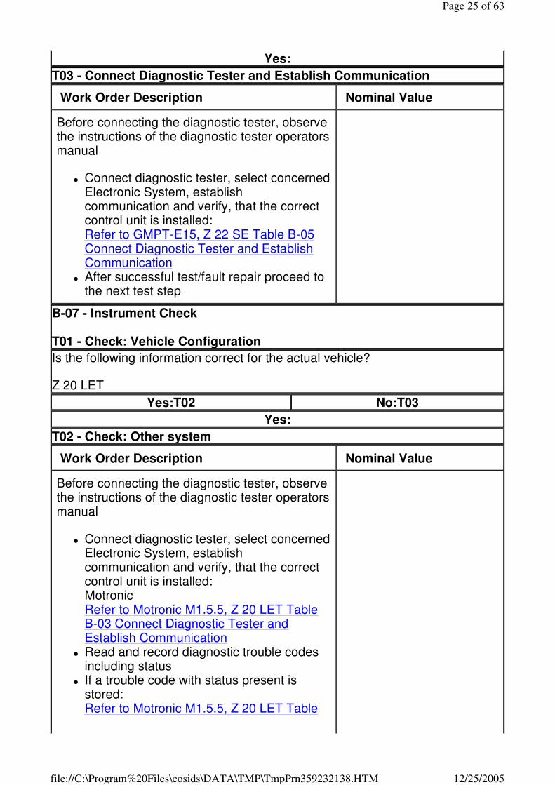
Before connecting the diagnostic tester, observe the instructions of the diagnostic tester operators manual
� Connect diagnostic tester, select concerned Electronic System, establish communication and verify, that the correct control unit is installed: Refer to GMPT-E15, Z 22 SE Table B-05 Connect Diagnostic Tester and Establish Communication
� After successful test/fault repair proceed to the next test step
B-07 - Instrument Check T01 - Check: Vehicle Configuration
Is the following information correct for the actual vehicle?
Z 20 LET
Yes:T02 No:T03
Yes:
T02 - Check: Other system
Work Order Description Nominal Value
Before connecting the diagnostic tester, observe the instructions of the diagnostic tester operators manual
� Connect diagnostic tester, select concerned Electronic System, establish communication and verify, that the correct control unit is installed: Motronic Refer to Motronic M1.5.5, Z 20 LET Table B-03 Connect Diagnostic Tester and Establish Communication
� Read and record diagnostic trouble codes including status
� If a trouble code with status present is stored: Refer to Motronic M1.5.5, Z 20 LET Table
Page 25 of 63
12/25/2005file://C:\Program%20Files\cosids\DATA\TMP\TmpPrn359232138.HTM
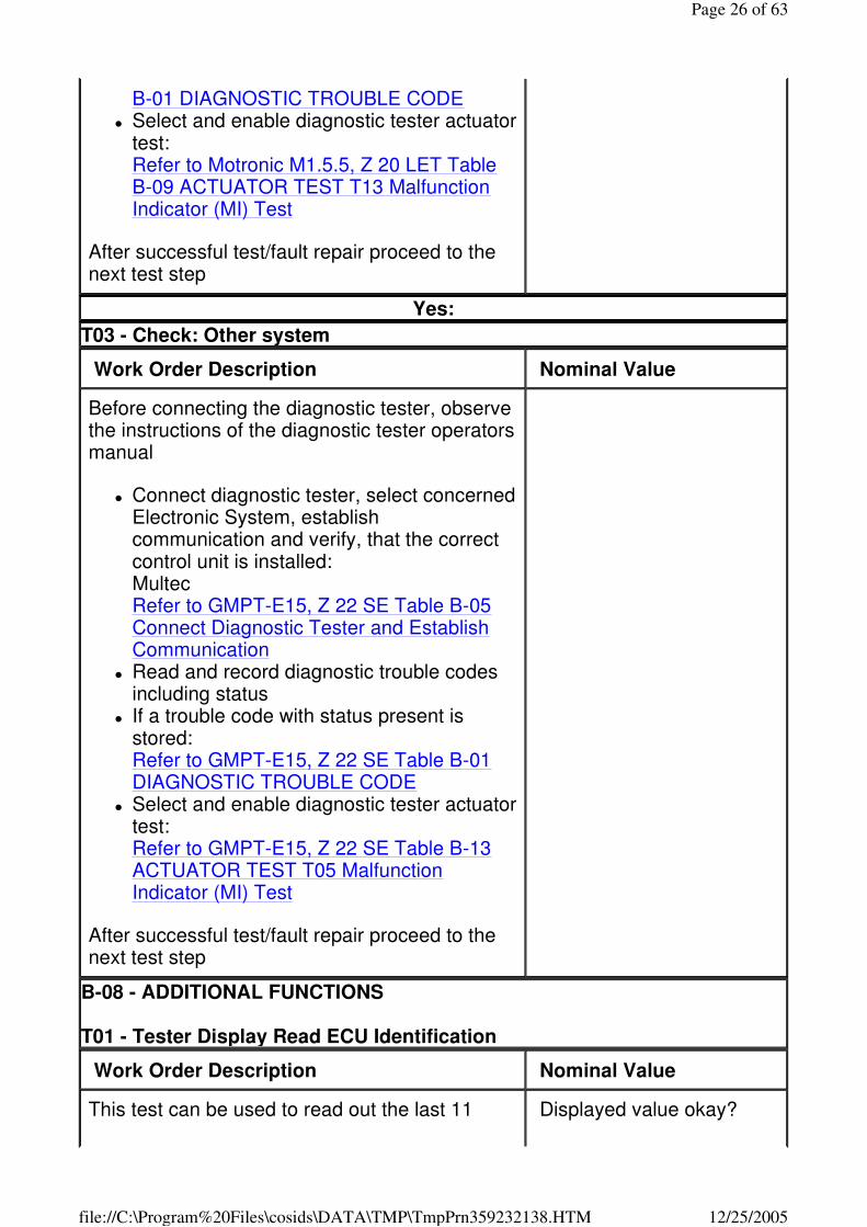
B-01 DIAGNOSTIC TROUBLE CODE � Select and enable diagnostic tester actuator
test: Refer to Motronic M1.5.5, Z 20 LET Table B-09 ACTUATOR TEST T13 Malfunction Indicator (MI) Test
After successful test/fault repair proceed to the next test step
Yes:
T03 - Check: Other system
Work Order Description Nominal Value
Before connecting the diagnostic tester, observe the instructions of the diagnostic tester operators manual
� Connect diagnostic tester, select concerned Electronic System, establish communication and verify, that the correct control unit is installed: Multec Refer to GMPT-E15, Z 22 SE Table B-05 Connect Diagnostic Tester and Establish Communication
� Read and record diagnostic trouble codes including status
� If a trouble code with status present is stored: Refer to GMPT-E15, Z 22 SE Table B-01 DIAGNOSTIC TROUBLE CODE
� Select and enable diagnostic tester actuator test: Refer to GMPT-E15, Z 22 SE Table B-13 ACTUATOR TEST T05 Malfunction Indicator (MI) Test
After successful test/fault repair proceed to the next test step
B-08 - ADDITIONAL FUNCTIONS T01 - Tester Display Read ECU Identification
Work Order Description Nominal Value
This test can be used to read out the last 11 Displayed value okay?
Page 26 of 63
12/25/2005file://C:\Program%20Files\cosids\DATA\TMP\TmpPrn359232138.HTM
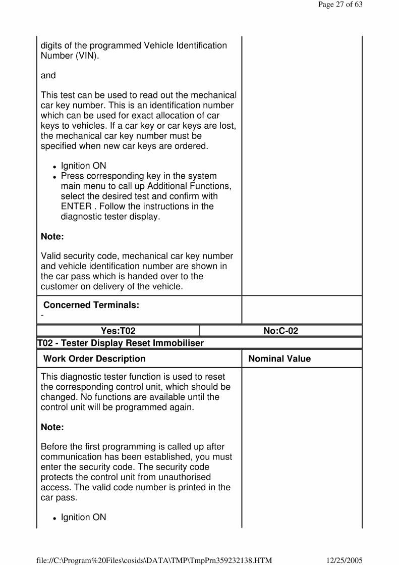
digits of the programmed Vehicle Identification Number (VIN).
and
This test can be used to read out the mechanical car key number. This is an identification number which can be used for exact allocation of car keys to vehicles. If a car key or car keys are lost, the mechanical car key number must be specified when new car keys are ordered.
� Ignition ON � Press corresponding key in the system
main menu to call up Additional Functions, select the desired test and confirm with ENTER . Follow the instructions in the diagnostic tester display.
Note:
Valid security code, mechanical car key number and vehicle identification number are shown in the car pass which is handed over to the customer on delivery of the vehicle.
Concerned Terminals: -
Yes:T02 No:C-02
T02 - Tester Display Reset Immobiliser
Work Order Description Nominal Value
This diagnostic tester function is used to reset the corresponding control unit, which should be changed. No functions are available until the control unit will be programmed again.
Note:
Before the first programming is called up after communication has been established, you must enter the security code. The security code protects the control unit from unauthorised access. The valid code number is printed in the car pass.
� Ignition ON
Page 27 of 63
12/25/2005file://C:\Program%20Files\cosids\DATA\TMP\TmpPrn359232138.HTM
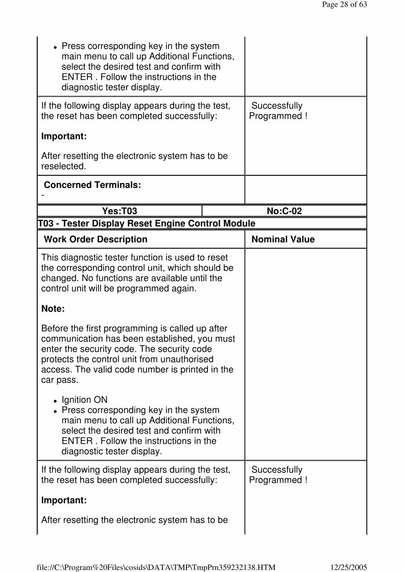
� Press corresponding key in the system main menu to call up Additional Functions, select the desired test and confirm with ENTER . Follow the instructions in the diagnostic tester display.
If the following display appears during the test, the reset has been completed successfully:
Important:
After resetting the electronic system has to be reselected.
Successfully Programmed !
Concerned Terminals: -
Yes:T03 No:C-02
T03 - Tester Display Reset Engine Control Module
Work Order Description Nominal Value
This diagnostic tester function is used to reset the corresponding control unit, which should be changed. No functions are available until the control unit will be programmed again.
Note:
Before the first programming is called up after communication has been established, you must enter the security code. The security code protects the control unit from unauthorised access. The valid code number is printed in the car pass.
� Ignition ON � Press corresponding key in the system
main menu to call up Additional Functions, select the desired test and confirm with ENTER . Follow the instructions in the diagnostic tester display.
If the following display appears during the test, the reset has been completed successfully:
Important:
After resetting the electronic system has to be
Successfully Programmed !
Page 28 of 63
12/25/2005file://C:\Program%20Files\cosids\DATA\TMP\TmpPrn359232138.HTM

reselected.
Concerned Terminals: -
Yes:T04 No:C-02
T04 - Tester Display Erase Transponder-Keys
Work Order Description Nominal Value
By means of this diagnostic tester function all transponder codes programmed into the immobiliser control unit are deleted. Neither of the two transponder car keys which belong to the vehicle and are supplied to the customer by the manufacturer will function after this.
Note:
Before the first programming is called up after communication has been established, you must enter the security code. The security code protects the control unit from unauthorised access. The valid code number is printed in the car pass.
� Ignition ON � Press corresponding key in the system
main menu to call up Additional Functions, select the desired test and confirm with ENTER . Follow the instructions in the diagnostic tester display.
If the following display appears during the test, erasing of the transponder codes has been completed successfully:
Important:
After programming the electronic system has to be reselected.
Programming successful!
Concerned Terminals: -
No:C-02
B-09 - PROGRAMMING T01 - Tester Display Program Immobiliser Function
Page 29 of 63
12/25/2005file://C:\Program%20Files\cosids\DATA\TMP\TmpPrn359232138.HTM
Work Order Description Nominal Value
With this diagnostic tester function the reset engine- and/or immobiliser control units are programmed in order to match these control units to another.
Note:
Before programming the immobiliser signal into the engine control unit the diagnostic tester must receive the programming approval from the TIS.
-
Before the first programming is called up after communication has been established, you must enter the security code. The security code protects the control unit from unauthorised access. The valid code number is printed in the car pass.
� Ignition ON � Press corresponding key in the system
main menu to call up Programming functions, select the desired test and confirm with ENTER . Follow the instructions in the diagnostic tester display.
Important:
When the immobiliser control unit and the engine control unit have been replaced at the same time, new transponders must be used.
After programming the electronic system has to be reselected.
Concerned Terminals: -
Yes:T02 No:C-02
T02 - Tester Display Program Immobiliser Output
Work Order Description Nominal Value
Important:
Always select "No Anti-Theft Warning System",
Page 30 of 63
12/25/2005file://C:\Program%20Files\cosids\DATA\TMP\TmpPrn359232138.HTM
even if an anti-theft warning system is installed. Otherwise not erasable PRESENT trouble codes will be set.
Note:
Before the first programming is called up after communication has been established, you must enter the security code. The security code protects the control unit from unauthorised access. The valid code number is printed in the car pass.
� Ignition ON � Press corresponding key in the system
main menu to call up Programming functions, select the desired test and confirm with ENTER . Follow the instructions in the diagnostic tester display.
If the following display appears at the end of the test, the test has been completed successfully:
Important:
After programming the electronic system has to be reselected.
Programming Completed !
Concerned Terminals: -
Yes:T03 No:C-02
T03 - Tester Display Program Transponder-Key
Work Order Description Nominal Value
The transponder car keys can be programmed consecutively and individually. For this, the immobiliser control unit reads out the car key's transponder code and stores it.
Important:
If a transponder car key is lost, the transponder codes in all remaining car keys must be erased and reprogrammed together with the new transponder car key, for safety reasons.
Note:
Page 31 of 63
12/25/2005file://C:\Program%20Files\cosids\DATA\TMP\TmpPrn359232138.HTM
Before programming the transponder car keys, the diagnostic tester must receive the programming approval from the TIS.
-
Before the first programming is called up after communication has been established, you must enter the security code. The security code protects the control unit from unauthorised access. The valid code number is printed in the car pass.
� Ignition ON � Press corresponding key in the system
main menu to call up Programming functions, select the desired test and confirm with ENTER . Follow the instructions in the diagnostic tester display.
If the following display appears during the test, car key programming has been completed successfully:
Note:
Programming Completed !
If the following display appears during the test, the immobiliser control unit must be programmed before programming of the transponder car keys can proceed.
Immobiliser Not Programmed !
Concerned Terminals: -
Yes:T04 No:C-06
T04 - Tester Display Program Mechanical Key Number
Work Order Description Nominal Value
The mechanical car key number consists of a letter and a four-digit number combination.
Note:
Before the first programming is called up after communication has been established, you must enter the security code. The security code protects the control unit from unauthorised access. The valid code number is printed in the
Page 32 of 63
12/25/2005file://C:\Program%20Files\cosids\DATA\TMP\TmpPrn359232138.HTM
car pass.
� Ignition ON � Press corresponding key in the system
main menu to call up Programming functions, select the desired test and confirm with ENTER . Follow the instructions in the diagnostic tester display.
If the following display appears at the end of the test, the test has been completed successfully:
Programming Completed !
Concerned Terminals: -
No:C-02
Yes:
B-10 - Check: Intermittent Faults T01 - Intermittent System Operation
Work Order Description Nominal Value
The following test steps may or may not be helpful, they are only a proposal.
-
Check Additional Information
� Check the newest Technical Information TI for tips regarding the appeared intermittent problems before proceeding with the diagnostic procedure.
Preliminary diagnostic check (visual inspection)
� Check all sensors, actuators and the wiring harness of the system for corrosion and damages.
� Check all connectors of the system for corrosion and for damaged terminals.
� Check all ground connections of the system for corrosion and damages
� Check if the fault was recognised in an area of strong electromagnetic sources e.g. near radio stations
Diagnostic Trouble Codes
Page 33 of 63
12/25/2005file://C:\Program%20Files\cosids\DATA\TMP\TmpPrn359232138.HTM

� Read and record trouble codes � Check for trouble codes with status
INTERMITTENT or NOT PRESENT. If a trouble code is stored this may indicate the circuit which has the intermittent condition.
� Use the following table to obtain the concerned functional group and perform the following additional test steps, while performing the troubleshooting in the C-x tables. Refer to Table B-05 Trouble Codes Move the related connectors, wiring harness and components in order to find the failure. Switch on all electric consumers by turns, because this can cause an electromagnetic interference in a circuit. Use the TECH 31 or an oscilloscope to observe the wiring harness for disturbances. Operate the system under different conditions over a considerable time.
Snapshot function of the Diagnostic tester and TIS / TIS2000
� Select the snapshot function of the Diagnostic Tester. Set the Diagnostic Tester to trigger on ANY CODE /CENTER and try to recreate the conditions that may cause the intermittent trouble code to be set (use the customer complaint information). Use the Diagnostic tester or TIS / TIS 2000 application to analyse the related datalist parameters. The disturbances in the signal can be observed at the trigger point where the trouble code is set.
� Use the following table to obtain the concerned functional group and perform the following additional test steps, while performing the troubleshooting in the C-x tables. Refer to Table B-05 Trouble Codes Refer to Table B-02 DATA LIST Move the related connectors, wiring harness and components in order to find the failure. Switch on all electric consumers
Page 34 of 63
12/25/2005file://C:\Program%20Files\cosids\DATA\TMP\TmpPrn359232138.HTM
by turns, because this can cause an electromagnetic interference in a circuit. Use the TECH 31 or an oscilloscope to observe the wiring harness for disturbances. Operate the system under different conditions over a considerable time.
� After successful test/fault repair proceed to the next test step
Yes:
B-11 - Programming 1 T01 - Check: Programming
Work Order Description Nominal Value
� Perform the following test step: Refer to Table B-09 PROGRAMMING T01 Program Immobiliser Function
� After successful test/fault repair proceed to the next test step
Yes:
B-12 - Programming 2 T01 - Check: Programming
Work Order Description Nominal Value
� Perform the following programming: Refer to Table B-09 PROGRAMMING T02 Program Immobiliser Output
� If a defect has been found in previous test steps, the following test can be skipped (follow result "YES"). Refer to Table C-02 Control Unit Hard- and Software
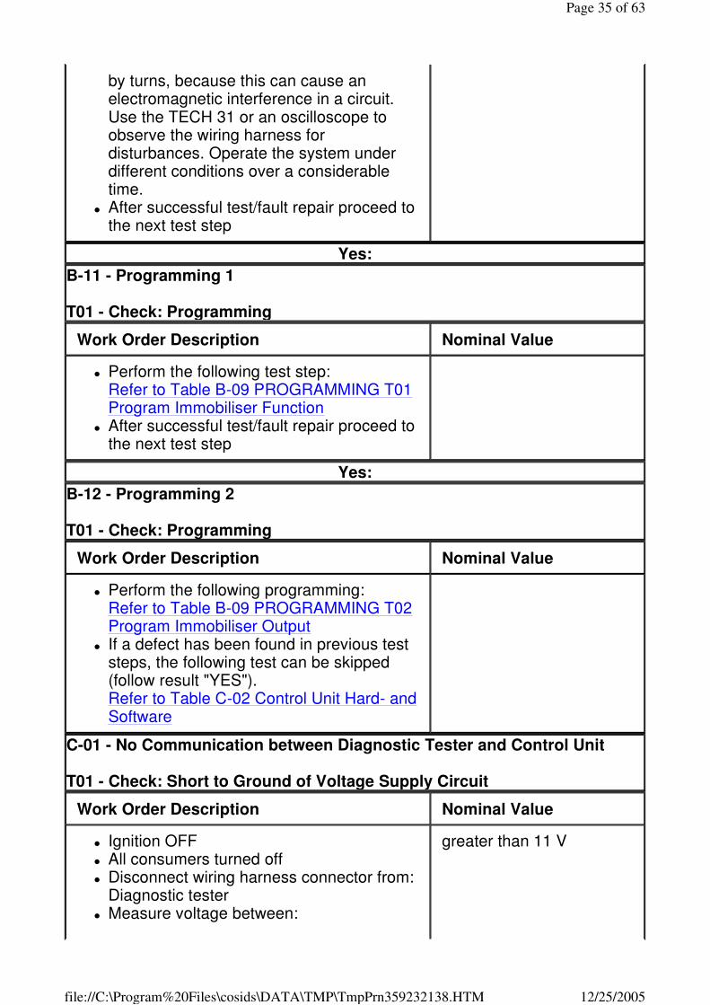
C-01 - No Communication between Diagnostic Tester and Control Unit T01 - Check: Short to Ground of Voltage Supply Circuit
Work Order Description Nominal Value
� Ignition OFF � All consumers turned off � Disconnect wiring harness connector from:
Diagnostic tester � Measure voltage between:
greater than 11 V
Page 35 of 63
12/25/2005file://C:\Program%20Files\cosids\DATA\TMP\TmpPrn359232138.HTM
G1 Battery Wiring harness connector (component side) terminal 30 & Ground
Yes:T02 No:E14
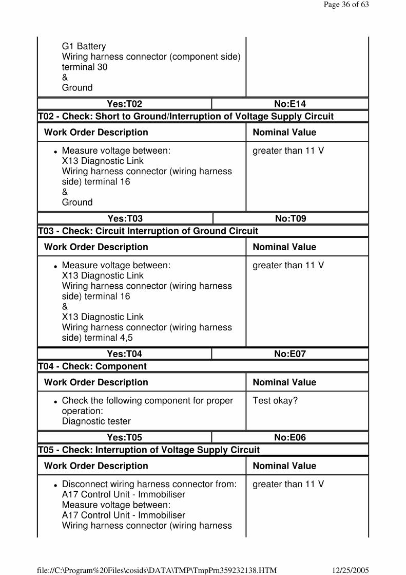
T02 - Check: Short to Ground/Interruption of Voltage Supply Circuit
Work Order Description Nominal Value
� Measure voltage between: X13 Diagnostic Link Wiring harness connector (wiring harness side) terminal 16 & Ground
greater than 11 V
Yes:T03 No:T09
T03 - Check: Circuit Interruption of Ground Circuit
Work Order Description Nominal Value
� Measure voltage between: X13 Diagnostic Link Wiring harness connector (wiring harness side) terminal 16 & X13 Diagnostic Link Wiring harness connector (wiring harness side) terminal 4,5
greater than 11 V
Yes:T04 No:E07
T04 - Check: Component
Work Order Description Nominal Value
� Check the following component for proper operation: Diagnostic tester
Test okay?
Yes:T05 No:E06
T05 - Check: Interruption of Voltage Supply Circuit
Work Order Description Nominal Value
� Disconnect wiring harness connector from: A17 Control Unit - Immobiliser Measure voltage between: A17 Control Unit - Immobiliser Wiring harness connector (wiring harness
greater than 11 V
Page 36 of 63
12/25/2005file://C:\Program%20Files\cosids\DATA\TMP\TmpPrn359232138.HTM
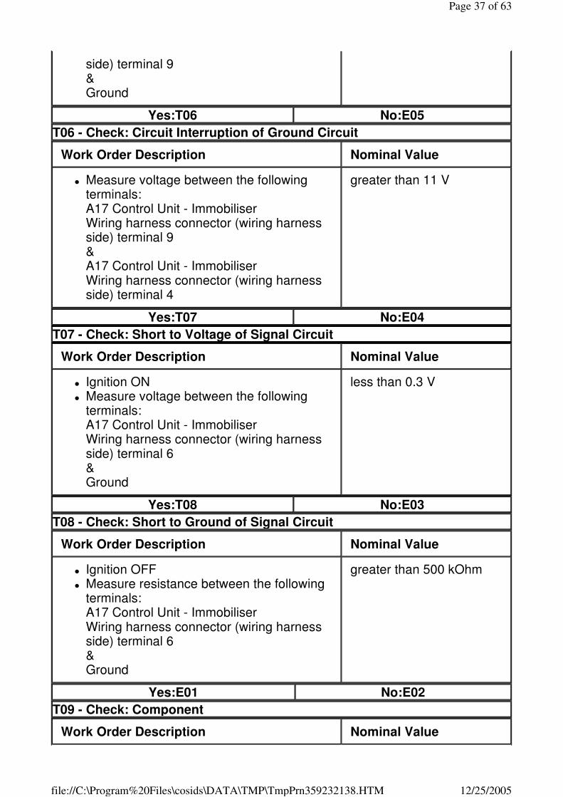
side) terminal 9 & Ground
Yes:T06 No:E05
T06 - Check: Circuit Interruption of Ground Circuit
Work Order Description Nominal Value
� Measure voltage between the following terminals: A17 Control Unit - Immobiliser Wiring harness connector (wiring harness side) terminal 9 & A17 Control Unit - Immobiliser Wiring harness connector (wiring harness side) terminal 4
greater than 11 V
Yes:T07 No:E04
T07 - Check: Short to Voltage of Signal Circuit
Work Order Description Nominal Value
� Ignition ON � Measure voltage between the following
terminals: A17 Control Unit - Immobiliser Wiring harness connector (wiring harness side) terminal 6 & Ground
less than 0.3 V
Yes:T08 No:E03
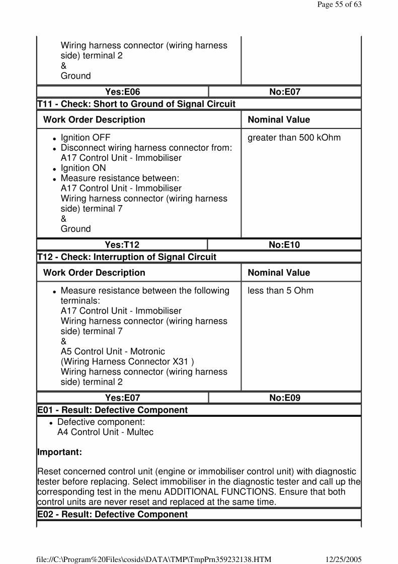
T08 - Check: Short to Ground of Signal Circuit
Work Order Description Nominal Value
� Ignition OFF � Measure resistance between the following
terminals: A17 Control Unit - Immobiliser Wiring harness connector (wiring harness side) terminal 6 & Ground
greater than 500 kOhm
Yes:E01 No:E02
T09 - Check: Component
Work Order Description Nominal Value
Page 37 of 63
12/25/2005file://C:\Program%20Files\cosids\DATA\TMP\TmpPrn359232138.HTM
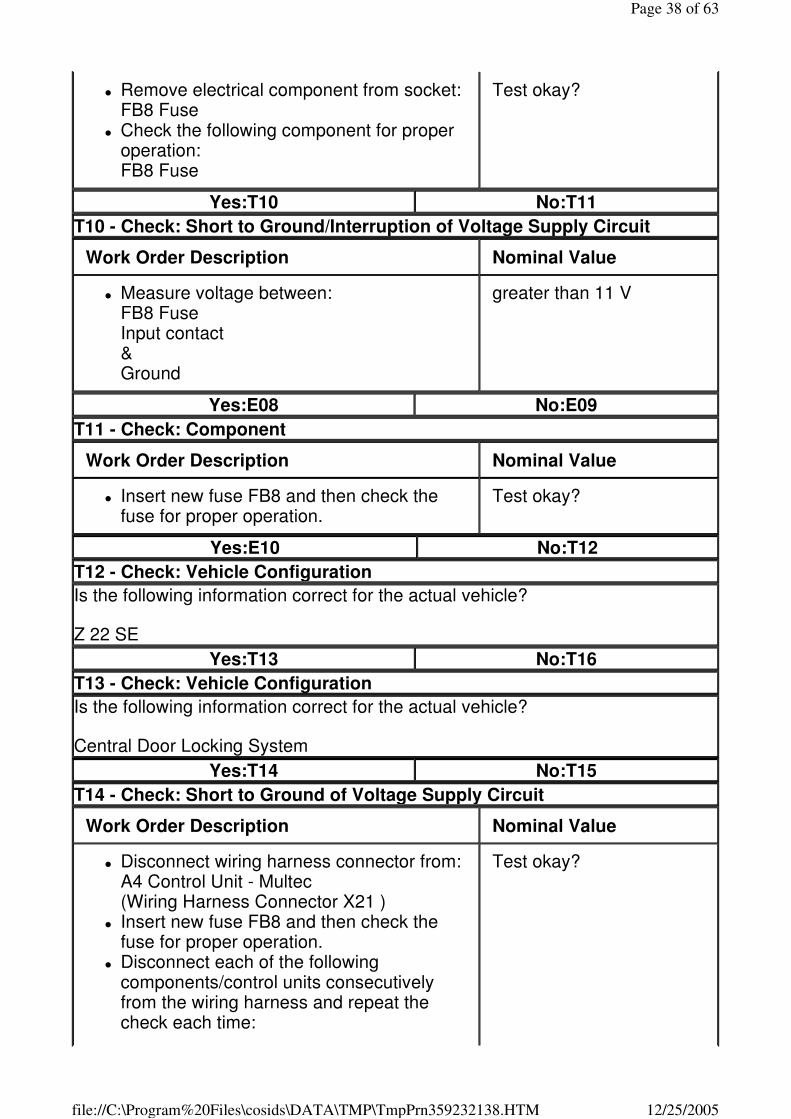
� Remove electrical component from socket: FB8 Fuse
� Check the following component for proper operation: FB8 Fuse
Test okay?
Yes:T10 No:T11
T10 - Check: Short to Ground/Interruption of Voltage Supply Circuit
Work Order Description Nominal Value
� Measure voltage between: FB8 Fuse Input contact & Ground
greater than 11 V
Yes:E08 No:E09
T11 - Check: Component
Work Order Description Nominal Value
� Insert new fuse FB8 and then check the fuse for proper operation.
Test okay?
Yes:E10 No:T12
T12 - Check: Vehicle Configuration
Is the following information correct for the actual vehicle?
Z 22 SE
Yes:T13 No:T16
T13 - Check: Vehicle Configuration
Is the following information correct for the actual vehicle?
Central Door Locking System
Yes:T14 No:T15
T14 - Check: Short to Ground of Voltage Supply Circuit
Work Order Description Nominal Value
� Disconnect wiring harness connector from: A4 Control Unit - Multec (Wiring Harness Connector X21 )
� Insert new fuse FB8 and then check the fuse for proper operation.
� Disconnect each of the following components/control units consecutively from the wiring harness and repeat the check each time:
Test okay?
Page 38 of 63
12/25/2005file://C:\Program%20Files\cosids\DATA\TMP\TmpPrn359232138.HTM
A13 Control Unit - Anti Theft Warning Unit A12 Control Unit - Central Locking A17 Control Unit - Immobiliser H1 Instrument
Yes:E11 No:E12
Yes:E11 No:E12
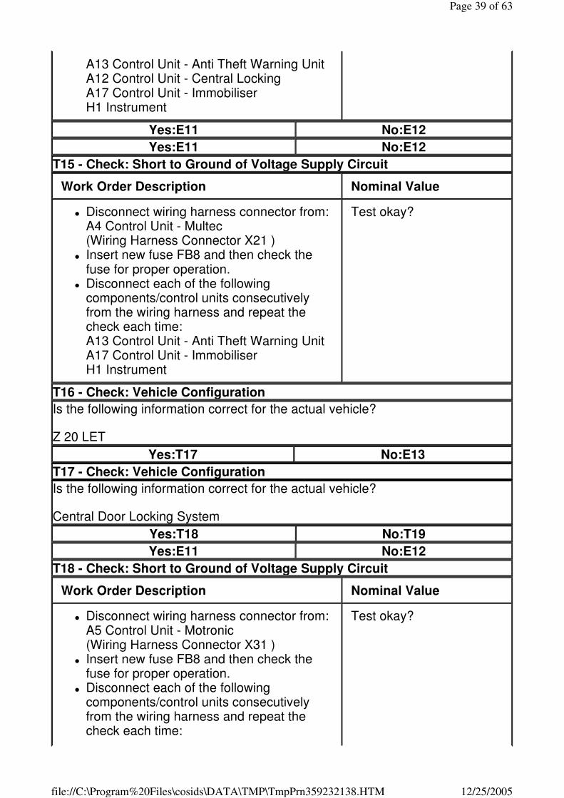
T15 - Check: Short to Ground of Voltage Supply Circuit
Work Order Description Nominal Value
� Disconnect wiring harness connector from: A4 Control Unit - Multec (Wiring Harness Connector X21 )
� Insert new fuse FB8 and then check the fuse for proper operation.
� Disconnect each of the following components/control units consecutively from the wiring harness and repeat the check each time: A13 Control Unit - Anti Theft Warning Unit A17 Control Unit - Immobiliser H1 Instrument
Test okay?
T16 - Check: Vehicle Configuration
Is the following information correct for the actual vehicle?
Z 20 LET
Yes:T17 No:E13
T17 - Check: Vehicle Configuration
Is the following information correct for the actual vehicle?
Central Door Locking System
Yes:T18 No:T19
Yes:E11 No:E12
T18 - Check: Short to Ground of Voltage Supply Circuit
Work Order Description Nominal Value
� Disconnect wiring harness connector from: A5 Control Unit - Motronic (Wiring Harness Connector X31 )
� Insert new fuse FB8 and then check the fuse for proper operation.
� Disconnect each of the following components/control units consecutively from the wiring harness and repeat the check each time:
Test okay?
Page 39 of 63
12/25/2005file://C:\Program%20Files\cosids\DATA\TMP\TmpPrn359232138.HTM
A13 Control Unit - Anti Theft Warning Unit A12 Control Unit - Central Locking A17 Control Unit - Immobiliser H1 Instrument
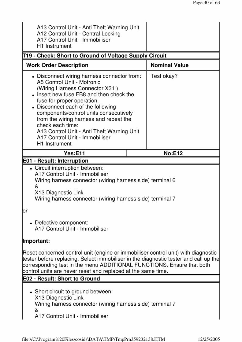
T19 - Check: Short to Ground of Voltage Supply Circuit
Work Order Description Nominal Value
� Disconnect wiring harness connector from: A5 Control Unit - Motronic (Wiring Harness Connector X31 )
� Insert new fuse FB8 and then check the fuse for proper operation.
� Disconnect each of the following components/control units consecutively from the wiring harness and repeat the check each time: A13 Control Unit - Anti Theft Warning Unit A17 Control Unit - Immobiliser H1 Instrument
Test okay?
Yes:E11 No:E12
E01 - Result: Interruption
� Circuit interruption between: A17 Control Unit - Immobiliser Wiring harness connector (wiring harness side) terminal 6 & X13 Diagnostic Link Wiring harness connector (wiring harness side) terminal 7
or
� Defective component: A17 Control Unit - Immobiliser
Important:
Reset concerned control unit (engine or immobiliser control unit) with diagnostic tester before replacing. Select immobiliser in the diagnostic tester and call up the corresponding test in the menu ADDITIONAL FUNCTIONS. Ensure that both control units are never reset and replaced at the same time.
E02 - Result: Short to Ground
� Short circuit to ground between: X13 Diagnostic Link Wiring harness connector (wiring harness side) terminal 7 & A17 Control Unit - Immobiliser
Page 40 of 63
12/25/2005file://C:\Program%20Files\cosids\DATA\TMP\TmpPrn359232138.HTM
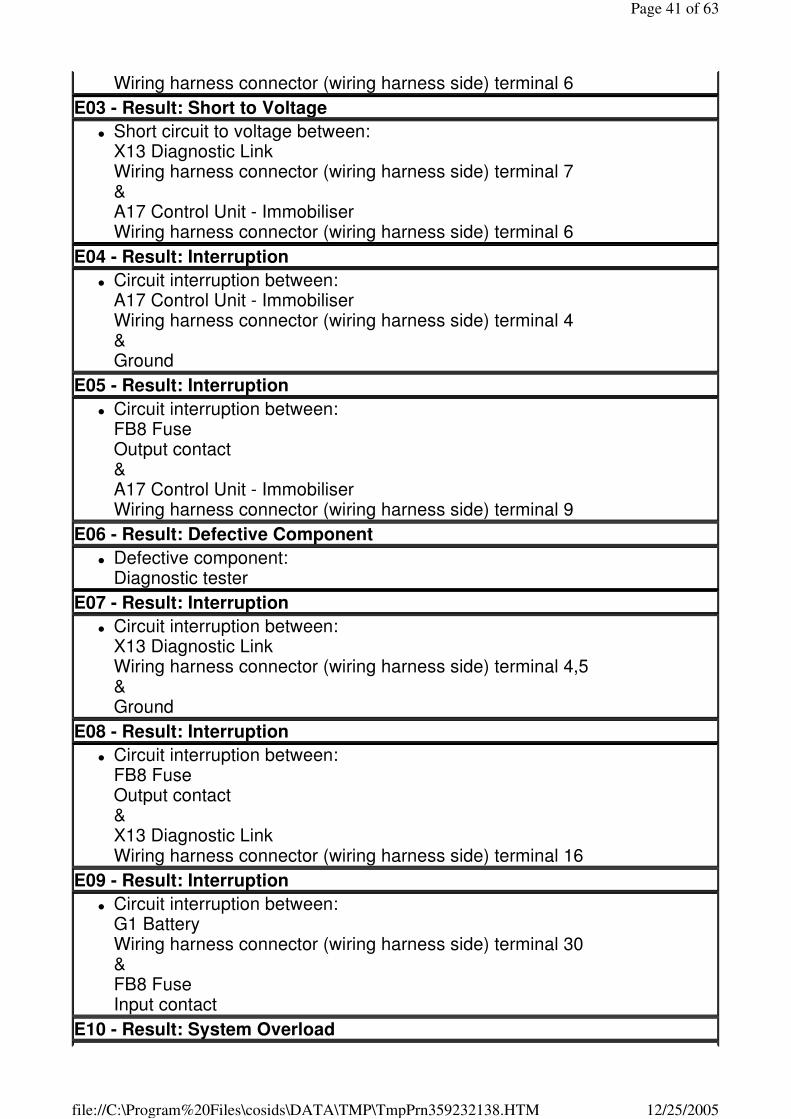
Wiring harness connector (wiring harness side) terminal 6
E03 - Result: Short to Voltage
� Short circuit to voltage between: X13 Diagnostic Link Wiring harness connector (wiring harness side) terminal 7 & A17 Control Unit - Immobiliser Wiring harness connector (wiring harness side) terminal 6
E04 - Result: Interruption
� Circuit interruption between: A17 Control Unit - Immobiliser Wiring harness connector (wiring harness side) terminal 4 & Ground
E05 - Result: Interruption
� Circuit interruption between: FB8 Fuse Output contact & A17 Control Unit - Immobiliser Wiring harness connector (wiring harness side) terminal 9
E06 - Result: Defective Component
� Defective component: Diagnostic tester
E07 - Result: Interruption
� Circuit interruption between: X13 Diagnostic Link Wiring harness connector (wiring harness side) terminal 4,5 & Ground
E08 - Result: Interruption
� Circuit interruption between: FB8 Fuse Output contact & X13 Diagnostic Link Wiring harness connector (wiring harness side) terminal 16
E09 - Result: Interruption
� Circuit interruption between: G1 Battery Wiring harness connector (wiring harness side) terminal 30 & FB8 Fuse Input contact
E10 - Result: System Overload
Page 41 of 63
12/25/2005file://C:\Program%20Files\cosids\DATA\TMP\TmpPrn359232138.HTM
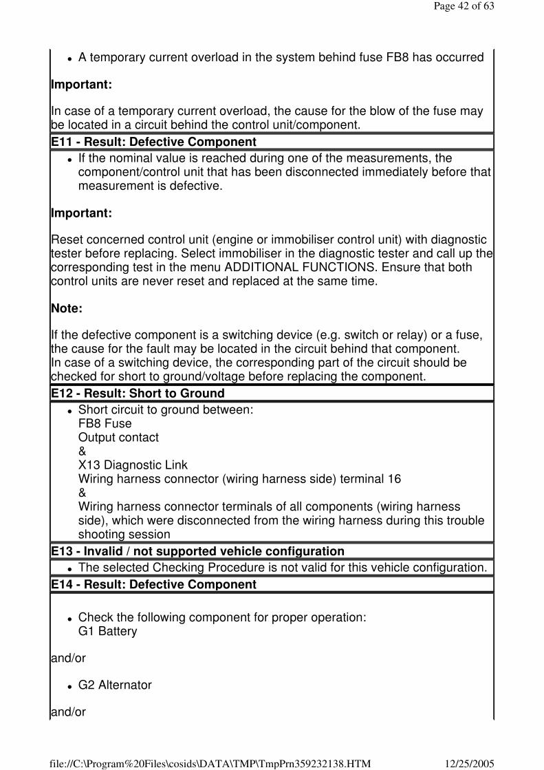
� A temporary current overload in the system behind fuse FB8 has occurred
Important:
In case of a temporary current overload, the cause for the blow of the fuse may be located in a circuit behind the control unit/component.
E11 - Result: Defective Component
� If the nominal value is reached during one of the measurements, the component/control unit that has been disconnected immediately before that measurement is defective.
Important:
Reset concerned control unit (engine or immobiliser control unit) with diagnostic tester before replacing. Select immobiliser in the diagnostic tester and call up the corresponding test in the menu ADDITIONAL FUNCTIONS. Ensure that both control units are never reset and replaced at the same time.
Note:
If the defective component is a switching device (e.g. switch or relay) or a fuse, the cause for the fault may be located in the circuit behind that component. In case of a switching device, the corresponding part of the circuit should be checked for short to ground/voltage before replacing the component.
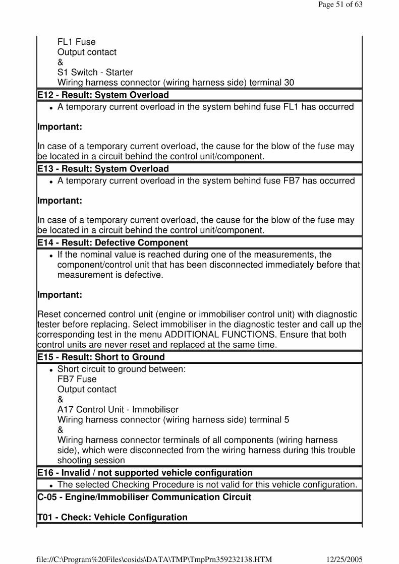
E12 - Result: Short to Ground
� Short circuit to ground between: FB8 Fuse Output contact & X13 Diagnostic Link Wiring harness connector (wiring harness side) terminal 16 & Wiring harness connector terminals of all components (wiring harness side), which were disconnected from the wiring harness during this trouble shooting session
E13 - Invalid / not supported vehicle configuration
� The selected Checking Procedure is not valid for this vehicle configuration.
E14 - Result: Defective Component
� Check the following component for proper operation: G1 Battery
and/or
� G2 Alternator
and/or
Page 42 of 63
12/25/2005file://C:\Program%20Files\cosids\DATA\TMP\TmpPrn359232138.HTM
� M1 Starter � Check the following circuit for proper operation:
Terminal 31 Terminal 30
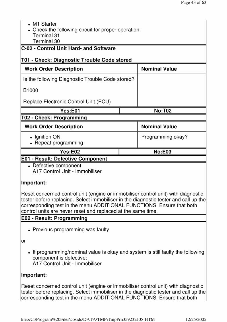
C-02 - Control Unit Hard- and Software T01 - Check: Diagnostic Trouble Code stored
Work Order Description Nominal Value
Is the following Diagnostic Trouble Code stored?
B1000
Replace Electronic Control Unit (ECU)
Yes:E01 No:T02
T02 - Check: Programming
Work Order Description Nominal Value
� Ignition ON � Repeat programming
Programming okay?
Yes:E02 No:E03
E01 - Result: Defective Component
� Defective component: A17 Control Unit - Immobiliser
Important:
Reset concerned control unit (engine or immobiliser control unit) with diagnostic tester before replacing. Select immobiliser in the diagnostic tester and call up the corresponding test in the menu ADDITIONAL FUNCTIONS. Ensure that both control units are never reset and replaced at the same time.
E02 - Result: Programming
� Previous programming was faulty
or
� If programming/nominal value is okay and system is still faulty the following component is defective: A17 Control Unit - Immobiliser
Important:
Reset concerned control unit (engine or immobiliser control unit) with diagnostic tester before replacing. Select immobiliser in the diagnostic tester and call up the corresponding test in the menu ADDITIONAL FUNCTIONS. Ensure that both
Page 43 of 63
12/25/2005file://C:\Program%20Files\cosids\DATA\TMP\TmpPrn359232138.HTM
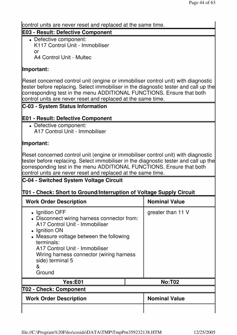
control units are never reset and replaced at the same time.
E03 - Result: Defective Component
� Defective component: K117 Control Unit - Immobiliser or A4 Control Unit - Multec
Important:
Reset concerned control unit (engine or immobiliser control unit) with diagnostic tester before replacing. Select immobiliser in the diagnostic tester and call up the corresponding test in the menu ADDITIONAL FUNCTIONS. Ensure that both control units are never reset and replaced at the same time.
C-03 - System Status Information E01 - Result: Defective Component
� Defective component: A17 Control Unit - Immobiliser
Important:
Reset concerned control unit (engine or immobiliser control unit) with diagnostic tester before replacing. Select immobiliser in the diagnostic tester and call up the corresponding test in the menu ADDITIONAL FUNCTIONS. Ensure that both control units are never reset and replaced at the same time.
C-04 - Switched System Voltage Circuit T01 - Check: Short to Ground/Interruption of Voltage Supply Circuit
Work Order Description Nominal Value
� Ignition OFF � Disconnect wiring harness connector from:
A17 Control Unit - Immobiliser � Ignition ON � Measure voltage between the following
terminals: A17 Control Unit - Immobiliser Wiring harness connector (wiring harness side) terminal 5 & Ground
greater than 11 V
Yes:E01 No:T02
T02 - Check: Component
Work Order Description Nominal Value
Page 44 of 63
12/25/2005file://C:\Program%20Files\cosids\DATA\TMP\TmpPrn359232138.HTM
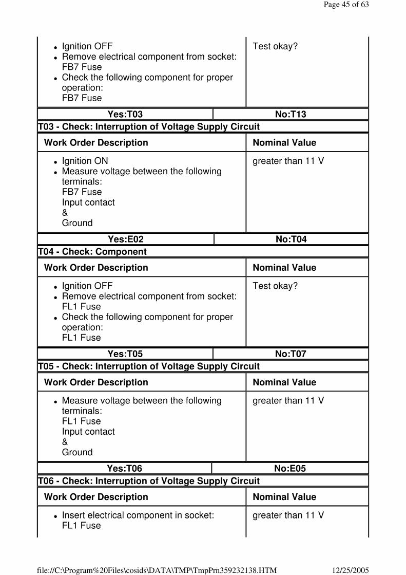
� Ignition OFF � Remove electrical component from socket:
FB7 Fuse � Check the following component for proper
operation: FB7 Fuse
Test okay?
Yes:T03 No:T13
T03 - Check: Interruption of Voltage Supply Circuit
Work Order Description Nominal Value
� Ignition ON � Measure voltage between the following
terminals: FB7 Fuse Input contact & Ground
greater than 11 V
Yes:E02 No:T04
T04 - Check: Component
Work Order Description Nominal Value
� Ignition OFF � Remove electrical component from socket:
FL1 Fuse � Check the following component for proper
operation: FL1 Fuse
Test okay?
Yes:T05 No:T07
T05 - Check: Interruption of Voltage Supply Circuit
Work Order Description Nominal Value
� Measure voltage between the following terminals: FL1 Fuse Input contact & Ground
greater than 11 V
Yes:T06 No:E05
T06 - Check: Interruption of Voltage Supply Circuit
Work Order Description Nominal Value
� Insert electrical component in socket: FL1 Fuse
greater than 11 V
Page 45 of 63
12/25/2005file://C:\Program%20Files\cosids\DATA\TMP\TmpPrn359232138.HTM
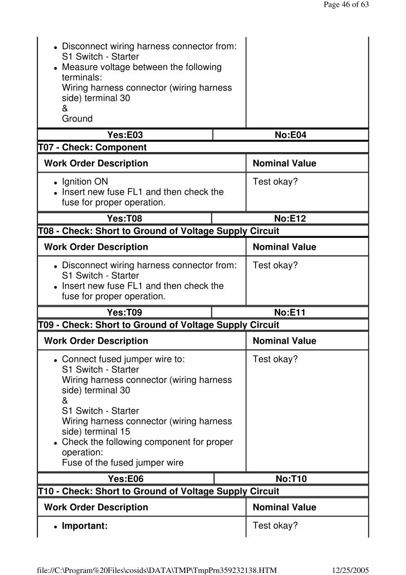
� Disconnect wiring harness connector from: S1 Switch - Starter
� Measure voltage between the following terminals: Wiring harness connector (wiring harness side) terminal 30 & Ground
Yes:E03 No:E04
T07 - Check: Component
Work Order Description Nominal Value
� Ignition ON � Insert new fuse FL1 and then check the
fuse for proper operation.
Test okay?
Yes:T08 No:E12
T08 - Check: Short to Ground of Voltage Supply Circuit
Work Order Description Nominal Value
� Disconnect wiring harness connector from: S1 Switch - Starter
� Insert new fuse FL1 and then check the fuse for proper operation.
Test okay?
Yes:T09 No:E11
T09 - Check: Short to Ground of Voltage Supply Circuit
Work Order Description Nominal Value
� Connect fused jumper wire to: S1 Switch - Starter Wiring harness connector (wiring harness side) terminal 30 & S1 Switch - Starter Wiring harness connector (wiring harness side) terminal 15
� Check the following component for proper operation: Fuse of the fused jumper wire
Test okay?
Yes:E06 No:T10
T10 - Check: Short to Ground of Voltage Supply Circuit
Work Order Description Nominal Value
� Important: Test okay?
Page 46 of 63
12/25/2005file://C:\Program%20Files\cosids\DATA\TMP\TmpPrn359232138.HTM
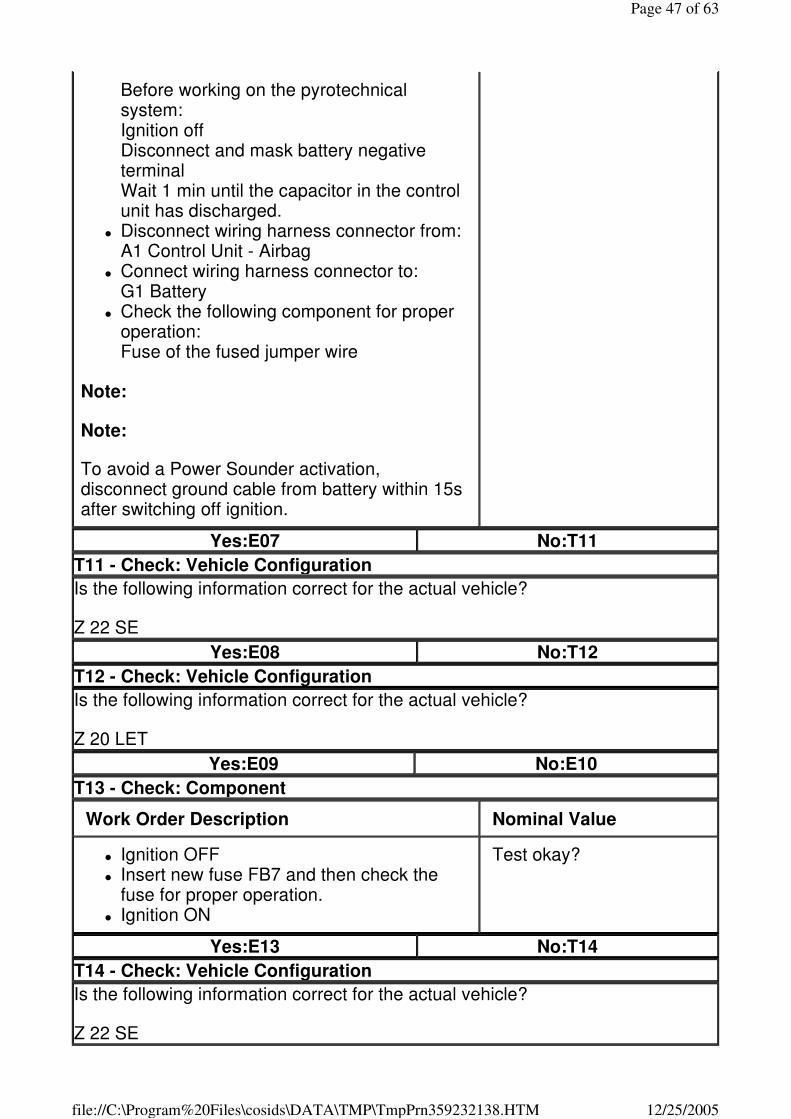
Before working on the pyrotechnical system: Ignition off Disconnect and mask battery negative terminal Wait 1 min until the capacitor in the control unit has discharged.
� Disconnect wiring harness connector from: A1 Control Unit - Airbag
� Connect wiring harness connector to: G1 Battery
� Check the following component for proper operation: Fuse of the fused jumper wire
Note:
Note:
To avoid a Power Sounder activation, disconnect ground cable from battery within 15s after switching off ignition.
Yes:E07 No:T11
T11 - Check: Vehicle Configuration
Is the following information correct for the actual vehicle?
Z 22 SE
Yes:E08 No:T12
T12 - Check: Vehicle Configuration
Is the following information correct for the actual vehicle?
Z 20 LET
Yes:E09 No:E10
T13 - Check: Component
Work Order Description Nominal Value
� Ignition OFF � Insert new fuse FB7 and then check the
fuse for proper operation. � Ignition ON
Test okay?
Yes:E13 No:T14
T14 - Check: Vehicle Configuration
Is the following information correct for the actual vehicle?
Z 22 SE
Page 47 of 63
12/25/2005file://C:\Program%20Files\cosids\DATA\TMP\TmpPrn359232138.HTM
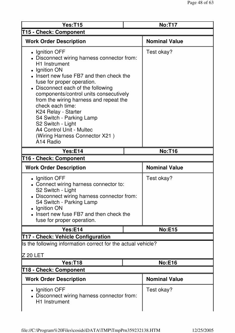
Yes:T15 No:T17
T15 - Check: Component
Work Order Description Nominal Value
� Ignition OFF � Disconnect wiring harness connector from:
H1 Instrument � Ignition ON � Insert new fuse FB7 and then check the
fuse for proper operation. � Disconnect each of the following
components/control units consecutively from the wiring harness and repeat the check each time: K24 Relay - Starter S4 Switch - Parking Lamp S2 Switch - Light A4 Control Unit - Multec (Wiring Harness Connector X21 ) A14 Radio
Test okay?
Yes:E14 No:T16
T16 - Check: Component
Work Order Description Nominal Value
� Ignition OFF � Connect wiring harness connector to:
S2 Switch - Light � Disconnect wiring harness connector from:
S4 Switch - Parking Lamp � Ignition ON � Insert new fuse FB7 and then check the
fuse for proper operation.
Test okay?
Yes:E14 No:E15
T17 - Check: Vehicle Configuration
Is the following information correct for the actual vehicle?
Z 20 LET
Yes:T18 No:E16
T18 - Check: Component
Work Order Description Nominal Value
� Ignition OFF � Disconnect wiring harness connector from:
H1 Instrument
Test okay?
Page 48 of 63
12/25/2005file://C:\Program%20Files\cosids\DATA\TMP\TmpPrn359232138.HTM
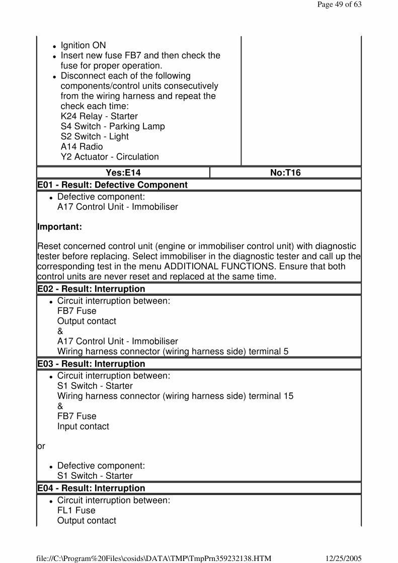
� Ignition ON � Insert new fuse FB7 and then check the
fuse for proper operation. � Disconnect each of the following
components/control units consecutively from the wiring harness and repeat the check each time: K24 Relay - Starter S4 Switch - Parking Lamp S2 Switch - Light A14 Radio Y2 Actuator - Circulation
Yes:E14 No:T16
E01 - Result: Defective Component
� Defective component: A17 Control Unit - Immobiliser
Important:
Reset concerned control unit (engine or immobiliser control unit) with diagnostic tester before replacing. Select immobiliser in the diagnostic tester and call up the corresponding test in the menu ADDITIONAL FUNCTIONS. Ensure that both control units are never reset and replaced at the same time.
E02 - Result: Interruption
� Circuit interruption between: FB7 Fuse Output contact & A17 Control Unit - Immobiliser Wiring harness connector (wiring harness side) terminal 5
E03 - Result: Interruption
� Circuit interruption between: S1 Switch - Starter Wiring harness connector (wiring harness side) terminal 15 & FB7 Fuse Input contact
or
� Defective component: S1 Switch - Starter
E04 - Result: Interruption
� Circuit interruption between: FL1 Fuse Output contact
Page 49 of 63
12/25/2005file://C:\Program%20Files\cosids\DATA\TMP\TmpPrn359232138.HTM
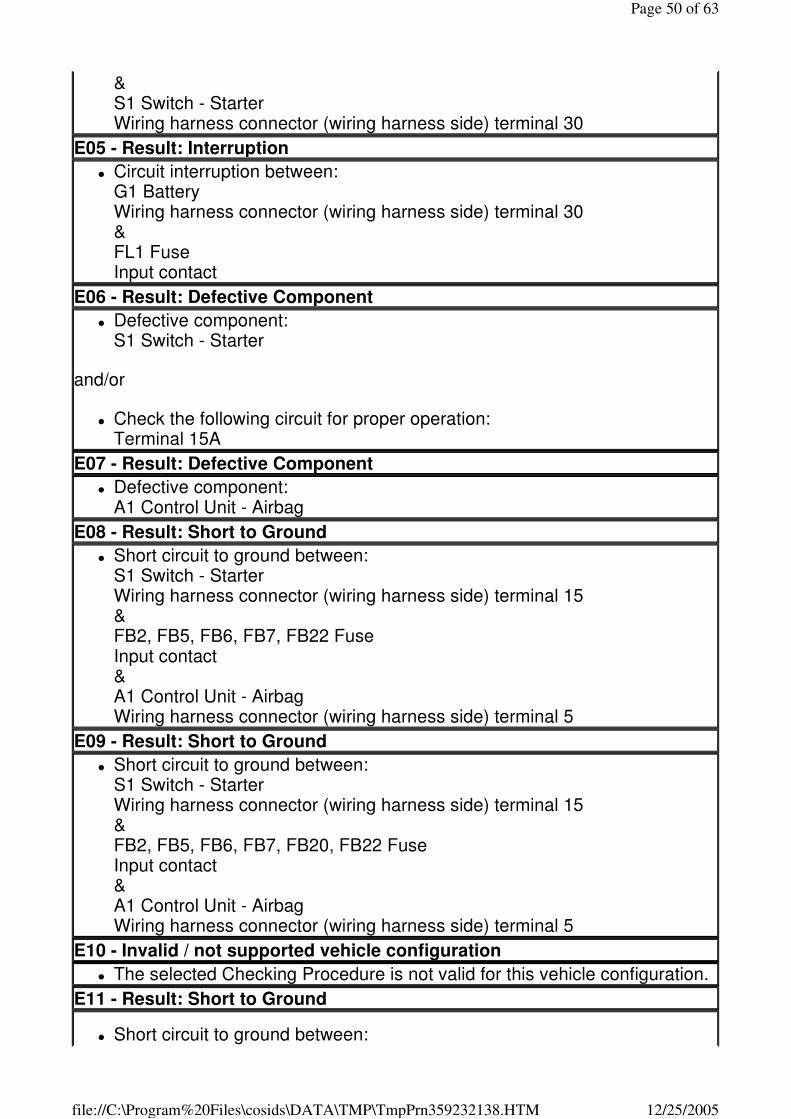
& S1 Switch - Starter Wiring harness connector (wiring harness side) terminal 30
E05 - Result: Interruption
� Circuit interruption between: G1 Battery Wiring harness connector (wiring harness side) terminal 30 & FL1 Fuse Input contact
E06 - Result: Defective Component
� Defective component: S1 Switch - Starter
and/or
� Check the following circuit for proper operation: Terminal 15A
E07 - Result: Defective Component
� Defective component: A1 Control Unit - Airbag
E08 - Result: Short to Ground
� Short circuit to ground between: S1 Switch - Starter Wiring harness connector (wiring harness side) terminal 15 & FB2, FB5, FB6, FB7, FB22 Fuse Input contact & A1 Control Unit - Airbag Wiring harness connector (wiring harness side) terminal 5
E09 - Result: Short to Ground
� Short circuit to ground between: S1 Switch - Starter Wiring harness connector (wiring harness side) terminal 15 & FB2, FB5, FB6, FB7, FB20, FB22 Fuse Input contact & A1 Control Unit - Airbag Wiring harness connector (wiring harness side) terminal 5
E10 - Invalid / not supported vehicle configuration
� The selected Checking Procedure is not valid for this vehicle configuration.
E11 - Result: Short to Ground
� Short circuit to ground between:
Page 50 of 63
12/25/2005file://C:\Program%20Files\cosids\DATA\TMP\TmpPrn359232138.HTM
FL1 Fuse Output contact & S1 Switch - Starter Wiring harness connector (wiring harness side) terminal 30
E12 - Result: System Overload
� A temporary current overload in the system behind fuse FL1 has occurred
Important:
In case of a temporary current overload, the cause for the blow of the fuse may be located in a circuit behind the control unit/component.
E13 - Result: System Overload
� A temporary current overload in the system behind fuse FB7 has occurred
Important:
In case of a temporary current overload, the cause for the blow of the fuse may be located in a circuit behind the control unit/component.
E14 - Result: Defective Component
� If the nominal value is reached during one of the measurements, the component/control unit that has been disconnected immediately before that measurement is defective.
Important:
Reset concerned control unit (engine or immobiliser control unit) with diagnostic tester before replacing. Select immobiliser in the diagnostic tester and call up the corresponding test in the menu ADDITIONAL FUNCTIONS. Ensure that both control units are never reset and replaced at the same time.
E15 - Result: Short to Ground
� Short circuit to ground between: FB7 Fuse Output contact & A17 Control Unit - Immobiliser Wiring harness connector (wiring harness side) terminal 5 & Wiring harness connector terminals of all components (wiring harness side), which were disconnected from the wiring harness during this trouble shooting session
E16 - Invalid / not supported vehicle configuration
� The selected Checking Procedure is not valid for this vehicle configuration.
C-05 - Engine/Immobiliser Communication Circuit T01 - Check: Vehicle Configuration
Page 51 of 63
12/25/2005file://C:\Program%20Files\cosids\DATA\TMP\TmpPrn359232138.HTM
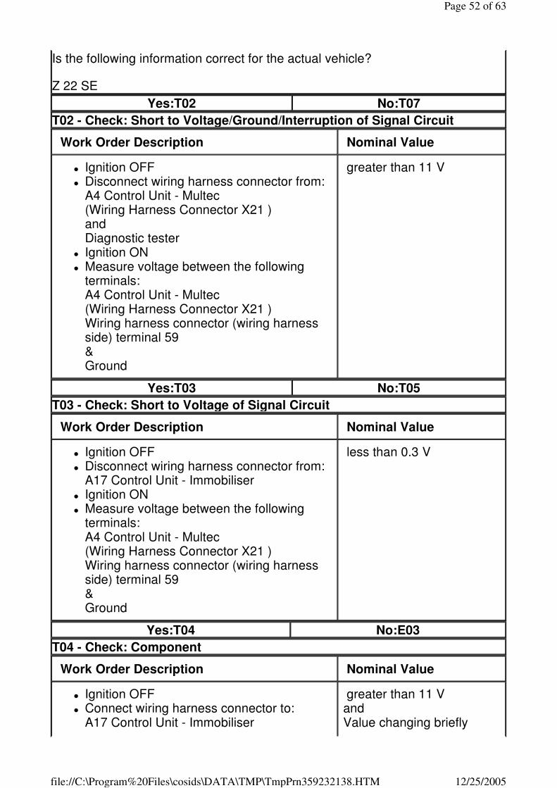
Is the following information correct for the actual vehicle?
Z 22 SE
Yes:T02 No:T07
T02 - Check: Short to Voltage/Ground/Interruption of Signal Circuit
Work Order Description Nominal Value
� Ignition OFF � Disconnect wiring harness connector from:
A4 Control Unit - Multec (Wiring Harness Connector X21 ) and Diagnostic tester
� Ignition ON � Measure voltage between the following
terminals: A4 Control Unit - Multec (Wiring Harness Connector X21 ) Wiring harness connector (wiring harness side) terminal 59 & Ground
greater than 11 V
Yes:T03 No:T05
T03 - Check: Short to Voltage of Signal Circuit
Work Order Description Nominal Value
� Ignition OFF � Disconnect wiring harness connector from:
A17 Control Unit - Immobiliser � Ignition ON � Measure voltage between the following
terminals: A4 Control Unit - Multec (Wiring Harness Connector X21 ) Wiring harness connector (wiring harness side) terminal 59 & Ground
less than 0.3 V
Yes:T04 No:E03
T04 - Check: Component
Work Order Description Nominal Value
� Ignition OFF � Connect wiring harness connector to:
A17 Control Unit - Immobiliser
greater than 11 V and Value changing briefly
Page 52 of 63
12/25/2005file://C:\Program%20Files\cosids\DATA\TMP\TmpPrn359232138.HTM
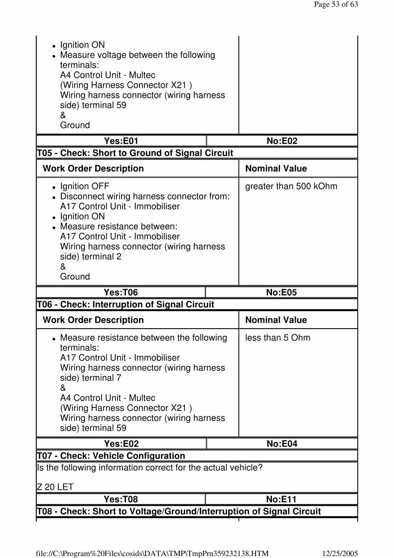
� Ignition ON � Measure voltage between the following
terminals: A4 Control Unit - Multec (Wiring Harness Connector X21 ) Wiring harness connector (wiring harness side) terminal 59 & Ground
Yes:E01 No:E02
T05 - Check: Short to Ground of Signal Circuit
Work Order Description Nominal Value
� Ignition OFF � Disconnect wiring harness connector from:
A17 Control Unit - Immobiliser � Ignition ON � Measure resistance between:
A17 Control Unit - Immobiliser Wiring harness connector (wiring harness side) terminal 2 & Ground
greater than 500 kOhm
Yes:T06 No:E05
T06 - Check: Interruption of Signal Circuit
Work Order Description Nominal Value
� Measure resistance between the following terminals: A17 Control Unit - Immobiliser Wiring harness connector (wiring harness side) terminal 7 & A4 Control Unit - Multec (Wiring Harness Connector X21 ) Wiring harness connector (wiring harness side) terminal 59
less than 5 Ohm
Yes:E02 No:E04
T07 - Check: Vehicle Configuration
Is the following information correct for the actual vehicle?
Z 20 LET
Yes:T08 No:E11
T08 - Check: Short to Voltage/Ground/Interruption of Signal Circuit
Page 53 of 63
12/25/2005file://C:\Program%20Files\cosids\DATA\TMP\TmpPrn359232138.HTM
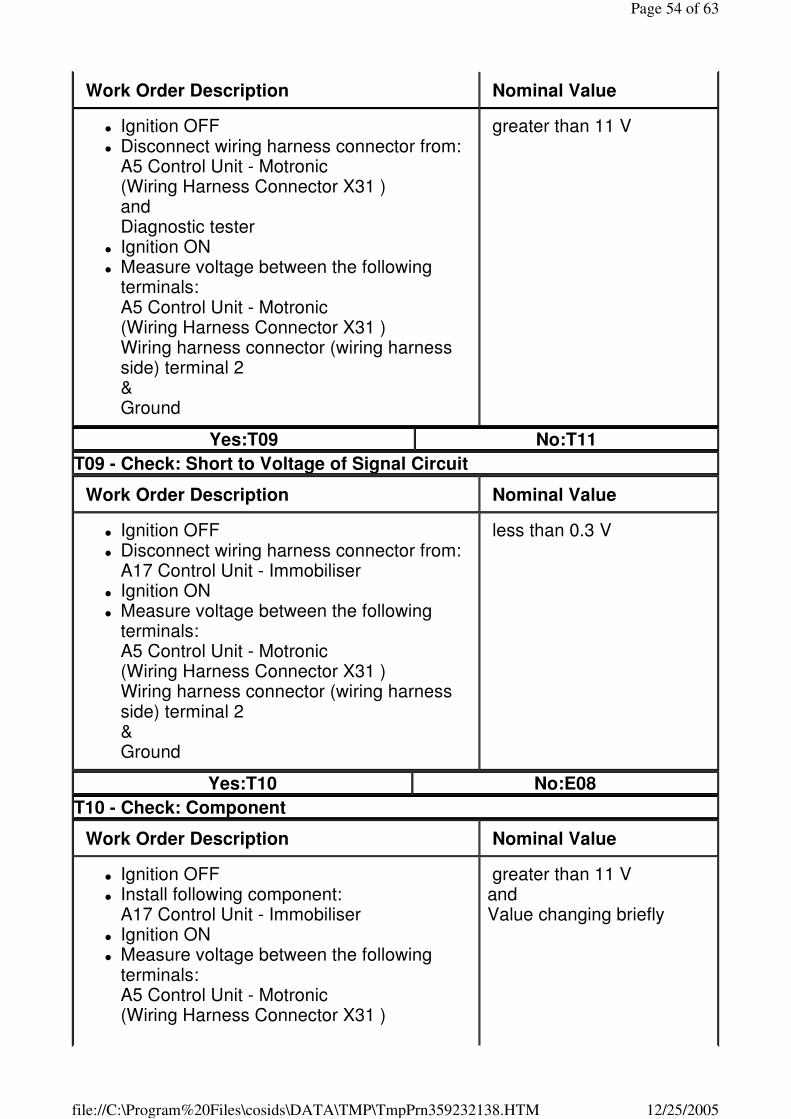
Work Order Description Nominal Value
� Ignition OFF � Disconnect wiring harness connector from:
A5 Control Unit - Motronic (Wiring Harness Connector X31 ) and Diagnostic tester
� Ignition ON � Measure voltage between the following
terminals: A5 Control Unit - Motronic (Wiring Harness Connector X31 ) Wiring harness connector (wiring harness side) terminal 2 & Ground
greater than 11 V
Yes:T09 No:T11
T09 - Check: Short to Voltage of Signal Circuit
Work Order Description Nominal Value
� Ignition OFF � Disconnect wiring harness connector from:
A17 Control Unit - Immobiliser � Ignition ON � Measure voltage between the following
terminals: A5 Control Unit - Motronic (Wiring Harness Connector X31 ) Wiring harness connector (wiring harness side) terminal 2 & Ground
less than 0.3 V
Yes:T10 No:E08
T10 - Check: Component
Work Order Description Nominal Value
� Ignition OFF � Install following component:
A17 Control Unit - Immobiliser � Ignition ON � Measure voltage between the following
terminals: A5 Control Unit - Motronic (Wiring Harness Connector X31 )
greater than 11 V and Value changing briefly
Page 54 of 63
12/25/2005file://C:\Program%20Files\cosids\DATA\TMP\TmpPrn359232138.HTM
Wiring harness connector (wiring harness side) terminal 2 & Ground
Yes:E06 No:E07
T11 - Check: Short to Ground of Signal Circuit
Work Order Description Nominal Value
� Ignition OFF � Disconnect wiring harness connector from:
A17 Control Unit - Immobiliser � Ignition ON � Measure resistance between:
A17 Control Unit - Immobiliser Wiring harness connector (wiring harness side) terminal 7 & Ground
greater than 500 kOhm
Yes:T12 No:E10
T12 - Check: Interruption of Signal Circuit
Work Order Description Nominal Value
� Measure resistance between the following terminals: A17 Control Unit - Immobiliser Wiring harness connector (wiring harness side) terminal 7 & A5 Control Unit - Motronic (Wiring Harness Connector X31 ) Wiring harness connector (wiring harness side) terminal 2
less than 5 Ohm
Yes:E07 No:E09
E01 - Result: Defective Component
� Defective component: A4 Control Unit - Multec
Important:
Reset concerned control unit (engine or immobiliser control unit) with diagnostic tester before replacing. Select immobiliser in the diagnostic tester and call up the corresponding test in the menu ADDITIONAL FUNCTIONS. Ensure that both control units are never reset and replaced at the same time.
E02 - Result: Defective Component
Page 55 of 63
12/25/2005file://C:\Program%20Files\cosids\DATA\TMP\TmpPrn359232138.HTM
� Defective component: A17 Control Unit - Immobiliser
Important:
Reset concerned control unit (engine or immobiliser control unit) with diagnostic tester before replacing. Select immobiliser in the diagnostic tester and call up the corresponding test in the menu ADDITIONAL FUNCTIONS. Ensure that both control units are never reset and replaced at the same time.
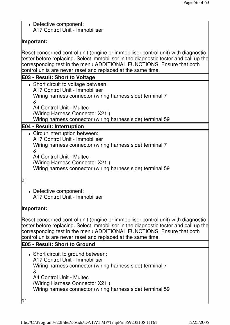
E03 - Result: Short to Voltage
� Short circuit to voltage between: A17 Control Unit - Immobiliser Wiring harness connector (wiring harness side) terminal 7 & A4 Control Unit - Multec (Wiring Harness Connector X21 ) Wiring harness connector (wiring harness side) terminal 59
E04 - Result: Interruption
� Circuit interruption between: A17 Control Unit - Immobiliser Wiring harness connector (wiring harness side) terminal 7 & A4 Control Unit - Multec (Wiring Harness Connector X21 ) Wiring harness connector (wiring harness side) terminal 59
or
� Defective component: A17 Control Unit - Immobiliser
Important:
Reset concerned control unit (engine or immobiliser control unit) with diagnostic tester before replacing. Select immobiliser in the diagnostic tester and call up the corresponding test in the menu ADDITIONAL FUNCTIONS. Ensure that both control units are never reset and replaced at the same time.
E05 - Result: Short to Ground
� Short circuit to ground between: A17 Control Unit - Immobiliser Wiring harness connector (wiring harness side) terminal 7 & A4 Control Unit - Multec (Wiring Harness Connector X21 ) Wiring harness connector (wiring harness side) terminal 59
or
Page 56 of 63
12/25/2005file://C:\Program%20Files\cosids\DATA\TMP\TmpPrn359232138.HTM
� Defective component: A17 Control Unit - Immobiliser
Important:
Reset concerned control unit (engine or immobiliser control unit) with diagnostic tester before replacing. Select immobiliser in the diagnostic tester and call up the corresponding test in the menu ADDITIONAL FUNCTIONS. Ensure that both control units are never reset and replaced at the same time.
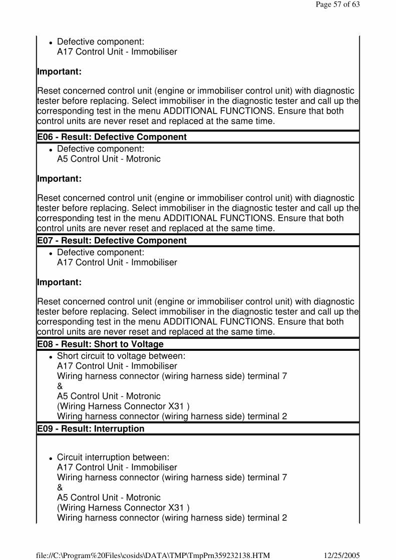
E06 - Result: Defective Component
� Defective component: A5 Control Unit - Motronic
Important:
Reset concerned control unit (engine or immobiliser control unit) with diagnostic tester before replacing. Select immobiliser in the diagnostic tester and call up the corresponding test in the menu ADDITIONAL FUNCTIONS. Ensure that both control units are never reset and replaced at the same time.
E07 - Result: Defective Component
� Defective component: A17 Control Unit - Immobiliser
Important:
Reset concerned control unit (engine or immobiliser control unit) with diagnostic tester before replacing. Select immobiliser in the diagnostic tester and call up the corresponding test in the menu ADDITIONAL FUNCTIONS. Ensure that both control units are never reset and replaced at the same time.
E08 - Result: Short to Voltage
� Short circuit to voltage between: A17 Control Unit - Immobiliser Wiring harness connector (wiring harness side) terminal 7 & A5 Control Unit - Motronic (Wiring Harness Connector X31 ) Wiring harness connector (wiring harness side) terminal 2
E09 - Result: Interruption
� Circuit interruption between: A17 Control Unit - Immobiliser Wiring harness connector (wiring harness side) terminal 7 & A5 Control Unit - Motronic (Wiring Harness Connector X31 ) Wiring harness connector (wiring harness side) terminal 2
Page 57 of 63
12/25/2005file://C:\Program%20Files\cosids\DATA\TMP\TmpPrn359232138.HTM
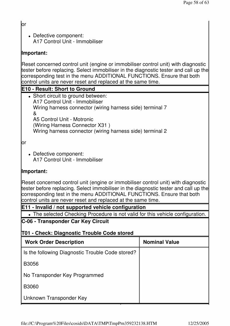
or
� Defective component: A17 Control Unit - Immobiliser
Important:
Reset concerned control unit (engine or immobiliser control unit) with diagnostic tester before replacing. Select immobiliser in the diagnostic tester and call up the corresponding test in the menu ADDITIONAL FUNCTIONS. Ensure that both control units are never reset and replaced at the same time.
E10 - Result: Short to Ground
� Short circuit to ground between: A17 Control Unit - Immobiliser Wiring harness connector (wiring harness side) terminal 7 & A5 Control Unit - Motronic (Wiring Harness Connector X31 ) Wiring harness connector (wiring harness side) terminal 2
or
� Defective component: A17 Control Unit - Immobiliser
Important:
Reset concerned control unit (engine or immobiliser control unit) with diagnostic tester before replacing. Select immobiliser in the diagnostic tester and call up the corresponding test in the menu ADDITIONAL FUNCTIONS. Ensure that both control units are never reset and replaced at the same time.
E11 - Invalid / not supported vehicle configuration
� The selected Checking Procedure is not valid for this vehicle configuration.
C-06 - Transponder Car Key Circuit T01 - Check: Diagnostic Trouble Code stored
Work Order Description Nominal Value
Is the following Diagnostic Trouble Code stored?
B3056
No Transponder Key Programmed
B3060
Unknown Transponder Key
Page 58 of 63
12/25/2005file://C:\Program%20Files\cosids\DATA\TMP\TmpPrn359232138.HTM
Yes:T02 No:T03
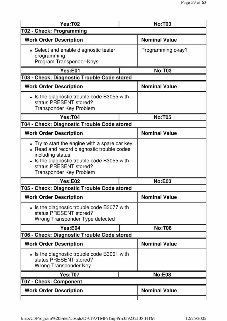
T02 - Check: Programming
Work Order Description Nominal Value
� Select and enable diagnostic tester programming: Program Transponder-Keys
Programming okay?
Yes:E01 No:T03
T03 - Check: Diagnostic Trouble Code stored
Work Order Description Nominal Value
� Is the diagnostic trouble code B3055 with status PRESENT stored? Transponder Key Problem
Yes:T04 No:T05
T04 - Check: Diagnostic Trouble Code stored
Work Order Description Nominal Value
� Try to start the engine with a spare car key � Read and record diagnostic trouble codes
including status � Is the diagnostic trouble code B3055 with
status PRESENT stored? Transponder Key Problem
Yes:E02 No:E03
T05 - Check: Diagnostic Trouble Code stored
Work Order Description Nominal Value
� Is the diagnostic trouble code B3077 with status PRESENT stored? Wrong Transponder Type detected
Yes:E04 No:T06
T06 - Check: Diagnostic Trouble Code stored
Work Order Description Nominal Value
� Is the diagnostic trouble code B3061 with status PRESENT stored? Wrong Transponder Key
Yes:T07 No:E08
T07 - Check: Component
Work Order Description Nominal Value
Page 59 of 63
12/25/2005file://C:\Program%20Files\cosids\DATA\TMP\TmpPrn359232138.HTM
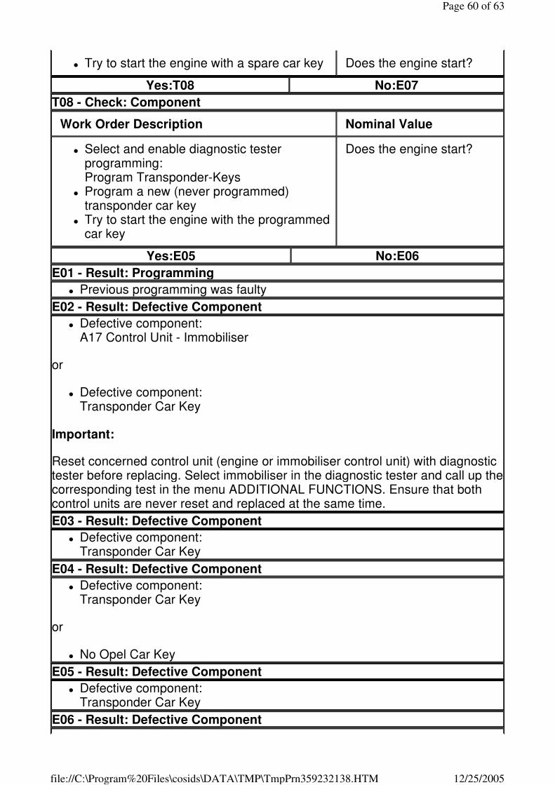
� Try to start the engine with a spare car key Does the engine start?
Yes:T08 No:E07
T08 - Check: Component
Work Order Description Nominal Value
� Select and enable diagnostic tester programming: Program Transponder-Keys
� Program a new (never programmed) transponder car key
� Try to start the engine with the programmed car key
Does the engine start?
Yes:E05 No:E06
E01 - Result: Programming
� Previous programming was faulty
E02 - Result: Defective Component
� Defective component: A17 Control Unit - Immobiliser
or
� Defective component: Transponder Car Key
Important:
Reset concerned control unit (engine or immobiliser control unit) with diagnostic tester before replacing. Select immobiliser in the diagnostic tester and call up the corresponding test in the menu ADDITIONAL FUNCTIONS. Ensure that both control units are never reset and replaced at the same time.
E03 - Result: Defective Component
� Defective component: Transponder Car Key
E04 - Result: Defective Component
� Defective component: Transponder Car Key
or
� No Opel Car Key
E05 - Result: Defective Component
� Defective component: Transponder Car Key
E06 - Result: Defective Component
Page 60 of 63
12/25/2005file://C:\Program%20Files\cosids\DATA\TMP\TmpPrn359232138.HTM
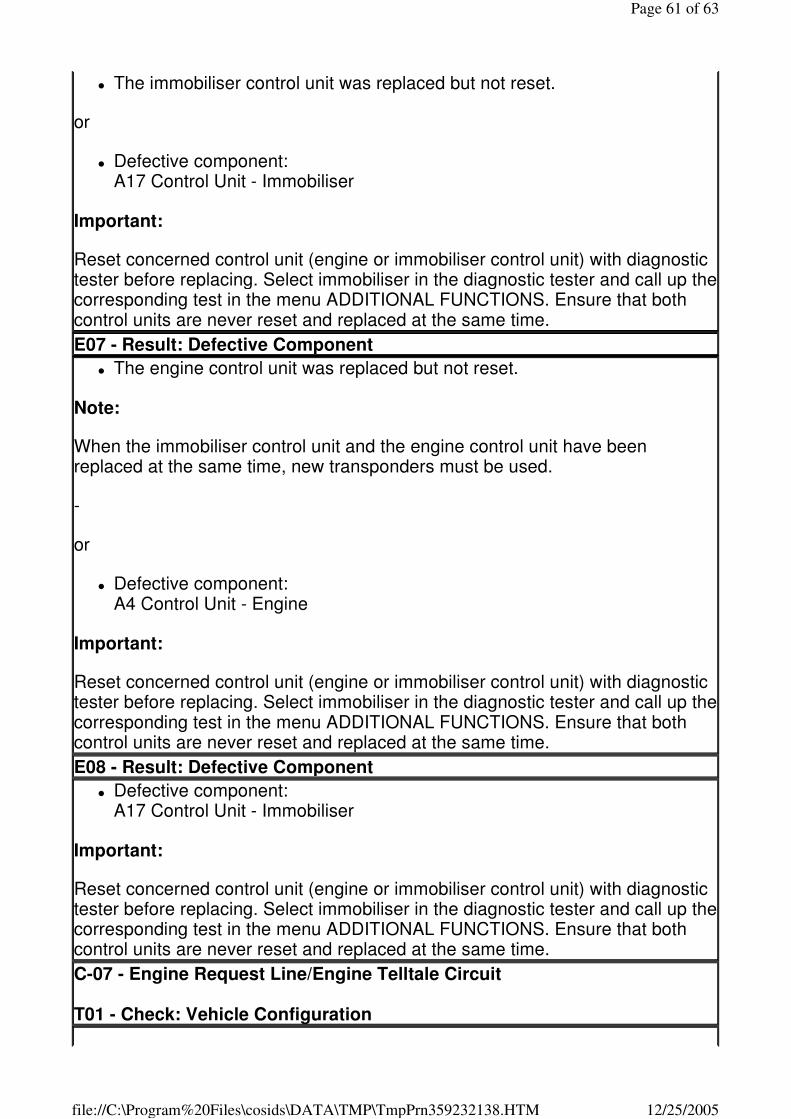
� The immobiliser control unit was replaced but not reset.
or
� Defective component: A17 Control Unit - Immobiliser
Important:
Reset concerned control unit (engine or immobiliser control unit) with diagnostic tester before replacing. Select immobiliser in the diagnostic tester and call up the corresponding test in the menu ADDITIONAL FUNCTIONS. Ensure that both control units are never reset and replaced at the same time.
E07 - Result: Defective Component
� The engine control unit was replaced but not reset.
Note:
When the immobiliser control unit and the engine control unit have been replaced at the same time, new transponders must be used.
-
or
� Defective component: A4 Control Unit - Engine
Important:
Reset concerned control unit (engine or immobiliser control unit) with diagnostic tester before replacing. Select immobiliser in the diagnostic tester and call up the corresponding test in the menu ADDITIONAL FUNCTIONS. Ensure that both control units are never reset and replaced at the same time.
E08 - Result: Defective Component
� Defective component: A17 Control Unit - Immobiliser
Important:
Reset concerned control unit (engine or immobiliser control unit) with diagnostic tester before replacing. Select immobiliser in the diagnostic tester and call up the corresponding test in the menu ADDITIONAL FUNCTIONS. Ensure that both control units are never reset and replaced at the same time.
C-07 - Engine Request Line/Engine Telltale Circuit T01 - Check: Vehicle Configuration
Page 61 of 63
12/25/2005file://C:\Program%20Files\cosids\DATA\TMP\TmpPrn359232138.HTM
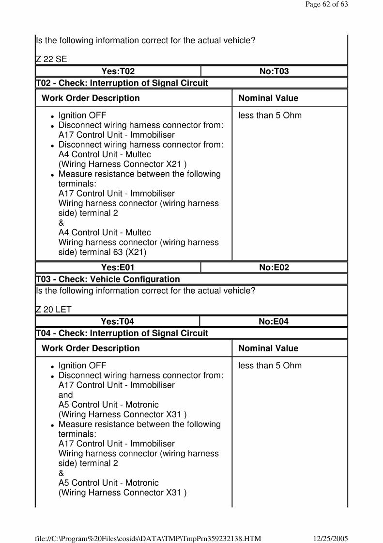
Is the following information correct for the actual vehicle?
Z 22 SE
Yes:T02 No:T03
T02 - Check: Interruption of Signal Circuit
Work Order Description Nominal Value
� Ignition OFF � Disconnect wiring harness connector from:
A17 Control Unit - Immobiliser � Disconnect wiring harness connector from:
A4 Control Unit - Multec (Wiring Harness Connector X21 )
� Measure resistance between the following terminals: A17 Control Unit - Immobiliser Wiring harness connector (wiring harness side) terminal 2 & A4 Control Unit - Multec Wiring harness connector (wiring harness side) terminal 63 (X21)
less than 5 Ohm
Yes:E01 No:E02
T03 - Check: Vehicle Configuration
Is the following information correct for the actual vehicle?
Z 20 LET
Yes:T04 No:E04
T04 - Check: Interruption of Signal Circuit
Work Order Description Nominal Value
� Ignition OFF � Disconnect wiring harness connector from:
A17 Control Unit - Immobiliser and A5 Control Unit - Motronic (Wiring Harness Connector X31 )
� Measure resistance between the following terminals: A17 Control Unit - Immobiliser Wiring harness connector (wiring harness side) terminal 2 & A5 Control Unit - Motronic (Wiring Harness Connector X31 )
less than 5 Ohm
Page 62 of 63
12/25/2005file://C:\Program%20Files\cosids\DATA\TMP\TmpPrn359232138.HTM
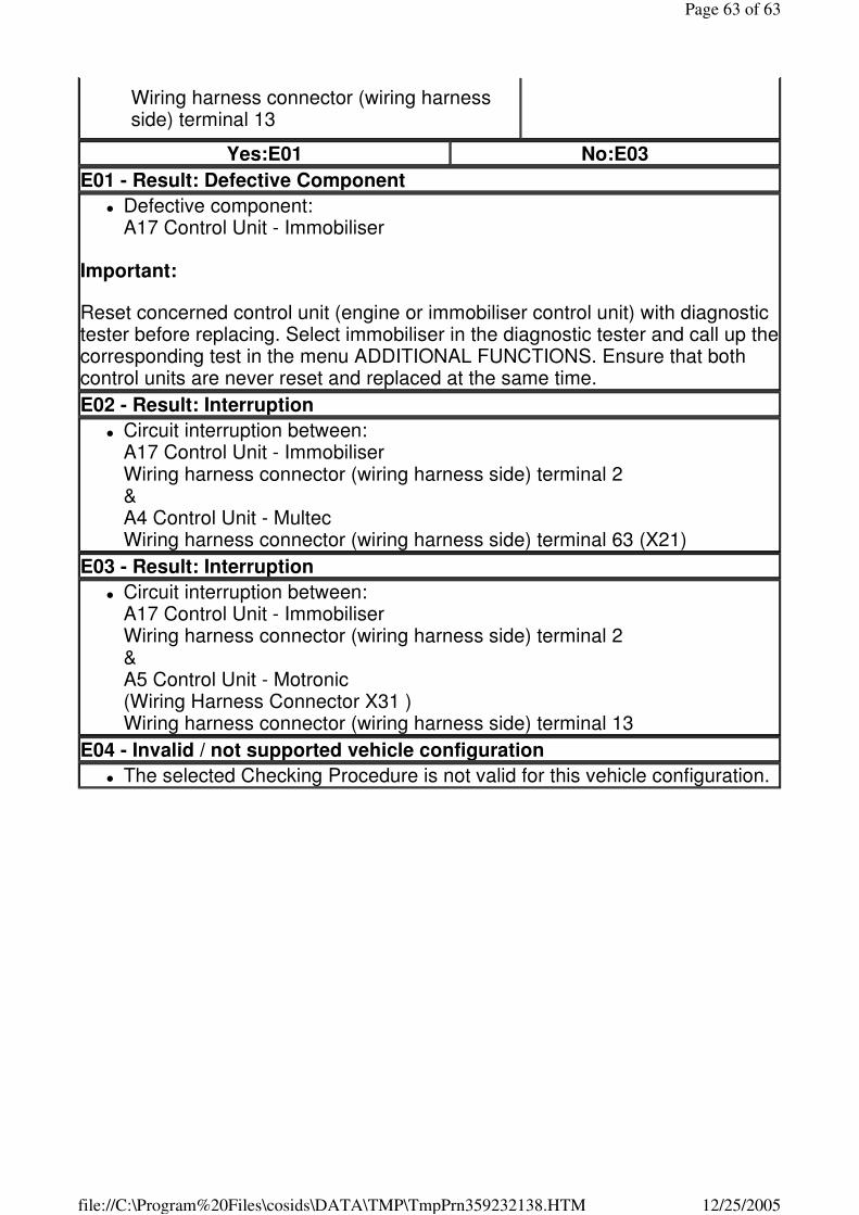
Wiring harness connector (wiring harness side) terminal 13
Yes:E01 No:E03
E01 - Result: Defective Component
� Defective component: A17 Control Unit - Immobiliser
Important:
Reset concerned control unit (engine or immobiliser control unit) with diagnostic tester before replacing. Select immobiliser in the diagnostic tester and call up the corresponding test in the menu ADDITIONAL FUNCTIONS. Ensure that both control units are never reset and replaced at the same time.
E02 - Result: Interruption
� Circuit interruption between: A17 Control Unit - Immobiliser Wiring harness connector (wiring harness side) terminal 2 & A4 Control Unit - Multec Wiring harness connector (wiring harness side) terminal 63 (X21)
E03 - Result: Interruption
� Circuit interruption between: A17 Control Unit - Immobiliser Wiring harness connector (wiring harness side) terminal 2 & A5 Control Unit - Motronic (Wiring Harness Connector X31 ) Wiring harness connector (wiring harness side) terminal 13
E04 - Invalid / not supported vehicle configuration
� The selected Checking Procedure is not valid for this vehicle configuration.
Page 63 of 63
12/25/2005file://C:\Program%20Files\cosids\DATA\TMP\TmpPrn359232138.HTM