instruction manual for installing high-strength boltsturnasure.com/pdf/install-usinch.pdf ·...
TRANSCRIPT
Instruction Manualfor Installing
HIGH-STRENGTHBOLTS
withDIRECT TENSION INDICATORS
(ASTM F959)INCH SERIES EDITION
TurnaSure LLC
®
TABLE OF CONTENTS
Introduction .................................................................................... 1
Theory of High-Strength Bolting .................................................... 2
Direct Tension Indicators (DTIs) .................................................... 3
Bolt Tensioning Using Plain Finish DTIs ........................................ 6
Bolt Tensioning Using Coated DTIs .............................................. 9
Recommended Bolt Installation Procedure.................................... 12
Problems Commonly Encountered WhenTensioning Bolts ...................................................................... 14
Tool Selection and Performance .................................................... 16
Checking for Specification Conformance ...................................... 17
DTI Identification Markings ............................................................ 20
Installation Instructions for Bridge Applicationsper AASHTO ..................................................Inside Back Cover
TurnaSure LLC 20 th Ed. Aug 2014International Headquarters Phone: 215-750-1300 Fax: 215-750-6300340 E. Maple Ave., Suite 206 800-525-7193 www.turnasure.comLanghorne, PA 19047
®

INCH1
INTRODUCTIONHigh-strength bolts are well established as economical and effi-
cient devices for connecting structural steel. When North Americandesign and construction practices are followed, the Specification forStructural Joints Using ASTM A325 or A490 Bolts, Approved by theResearch Council on Structural Connections, sets the basic rules fortheir use. Designers and inspectors should be thoroughly familiarwith this specification.
Direct Tension Indicators (DTIs) are recognized by many engi-neers as the most reliable method for ensuring correct installation ofhigh-strength bolts according to that specification for bothshear/bearing connections and connections requiring fully preten-sioned bolts.
This manual is written for engineers, construction superin-tendents, inspectors and iron workers to assist them in the properinstallation of high-strength bolts using DTIs. This will ensure thatbolts have been tensioned to the values required whether used inslip-critical connections, connections subjected to direct tension, orshear/bearing connections requiring fully pretensioned bolts. Theseinstructions are also valid when DTIs are specified for use with highstrength bolts in other connections as a device to ensure that allbolts have actually been tensioned.
The handbook discusses the theory of slip-critical connectionsor connections subjected to direct tension, proper installation ofDTIs, general rules for bolt installation, problems typically encoun-tered when installing high-strength bolts and many other subjectsrelative to high-strength bolting.
TurnaSure LLC has years of high-strength bolting experienceand provides a range of consultation activity including seminars, sitevisits, tool recommendations, specification commentary and trainingprograms. In addition TurnaSure LLC prepares instructional DVDs,published technical reports and articles for publication in trade jour-nals. Should you wish to receive any of this information or be placedon our mailing list, please contact us at the address shown on theinside cover.
A metric series edition of this manual is available upon request,or you can print the PDF version available on our web site.
INTRODUCTION High-strength bolts are well established as economical and efficient devices for connecting structural steel. When North Americandesign and construction practices are followed, the Specification for Structural Joints Using High-Strength Structural Bolts, Approved by the Research Council on Structural Connections, sets the basic rules for their use. Designers and inspectors should be thoroughly familiar with this specification. Direct Tension Indicators (DTIs) are recognized by many engineers as the most reliable method for ensuring correct installation of high-strength bolts for slip-critical connections and connections requiring fully pretensioned bolts. This manual is written for engineers, construction superintendents,inspectors and ironworkers to assist them in the proper installation of high-strength bolts using DTIs. This will ensure that bolts have been tensioned to the values required whether used in slip-critical connections, connections subjected to direct tension, or shear/bearing connections requiring fully pretensioned bolts. These instructions are also valid when DTIs are specified for use with high strength bolts in other connections as a device to ensure that all bolts have actually been tensioned. This manual discusses the theory of slip-critical connections or connections subjected to direct tension, proper installation of DTIs, general rules for bolt installation, problems typically encountered when installing high-strength bolts and many other subjects relative to high-strength bolting. TurnaSure LLC has years of high-strength bolting experience and provides a range of consultation activity including seminars, site visits, tool recommendations, specification commentary and training programs. In addition TurnaSure LLC prepares instructional DVDs, published technical reports and articles for publication in trade journals. Should you wish to receive any of this information or be placed on our mailing list, please contact us at the address shown on the inside cover or visit our website www.turnasure.com. A metric series edition of this manual is available upon request, or you can download a PDF version from our website.

2INCH
THEORY OF HIGH STRENGTH BOLTINGThe principle of slip-critical connections relies upon tensioning
each bolt in the connection to a specified minimum tension so thatthe desired clamping force will be induced in the connection inter-face. Shear loads are then transferred by frictional resistance in thejoint interface rather than by bearing on the bolt shanks and holefaces. In this type of connection there will be no movement of theconnected materials when the connection is subjected to theseloads. Movement in many types of joints is highly undesirable, hencethe development of the slip-critical connection. (Figure 1)
Figure 1
When tension loads are applied in the direction of the bolt axis,tensioning to a specified minimum tension is also important, particu-larly if the loads are cyclical and could induce loosening or fatiguefailure of the bolts. The clamping force at the specified minimum ten-sion should be greater than the applied loads. This will prevent theplies from separating or the bolts from developing any significantincrease in tension stress over the installed pretension stress.(Figure 2)
Figure 22INCH
THEORY OF HIGH STRENGTH BOLTINGThe principle of slip-critical connections relies upon tensioning
each bolt in the connection to a specified minimum tension so thatthe desired clamping force will be induced in the connection inter-face. Shear loads are then transferred by frictional resistance in thejoint interface rather than by bearing on the bolt shanks and holefaces. In this type of connection there will be no movement of theconnected materials when the connection is subjected to theseloads. Movement in many types of joints is highly undesirable, hencethe development of the slip-critical connection. (Figure 1)
Figure 1
When tension loads are applied in the direction of the bolt axis,tensioning to a specified minimum tension is also important, particu-larly if the loads are cyclical and could induce loosening or fatiguefailure of the bolts. The clamping force at the specified minimum ten-sion should be greater than the applied loads. This will prevent theplies from separating or the bolts from developing any significantincrease in tension stress over the installed pretension stress.(Figure 2)
Figure 2
THEORY OF HIGH STRENGTH BOLTING The principle of slip-critical connections relies upon tensioning each bolt in the connection to a specified minimum tension so that the desired clamping force will be induced in the connection interface. Service loads are then transferred by frictional resistance in the joint interface rather than by bearing on the bolt shanks and hole faces. In this type of connection there will be no movement of the connected materials when the connection is subjected to applied loads. Movement in many types of joints is highly undesirable, hence the development of the slip-critical connection. (Figure 1)
When tension loads are applied in the direction of the bolt axis, tensioning to a specified minimum tension is also important, particularly if the loads are cyclical and could induce loosening or fatigue failure of the bolts. The clamping force at the specified minimum tension should be significantly greater than the applied loads. This will prevent the plies from separating or the bolts from developing an increase in tension stress over the installed pretension stress. (Figure 2)

DIRECT TENSION INDICATORS (DTIs)Direct Tension Indicators (DTIs) are simple and extremely accu-
rate devices for ensuring that bolts have been installed above thespecified minimum tension value. Used properly they positivelyensure the correct amount of clamping force. Readers who haveinstalled high-strength bolts using “torque/tension” values willnotice that this manual does not relate torque to tension.Torque, or twisting force, is not a reliable measure of bolt ten-sion. DTIs measure tension regardless of applied torque.
A DTI is a hardened, washer-shaped device with protrusions,“bumps,” pressed out on one face, manufactured according to theprovisions of ASTM F959. The fact that it resembles a washer is inci-dental. It is, in fact, a precision made mechanical load cell, a devicefor tensioning which is covered by an ASTM Standard.
When a DTI is installed on a bolt with the “bumps” placedagainst the underside of the bolt head there are noticeable gapsbetween the “bumps.” As the nut is turned and the bolt tensioned, the“bumps” flatten. When the “bumps” are flattened so that the gapshave been reduced to the required dimension, the bolt has beenproperly tensioned and required clamping force is present. A DTIdoes not make it more difficult to tension a bolt, it merely shows thatthe bolt has been properly tensioned. (Figure 3)
Figure 3
Direct Tension Indicators are supplied either “plain finish,” that iswithout a coating, mechanically galvanized to ASTM B695 Class 55,or produced from “weathering steel” for use with Type 3 high-strengthbolts. Other coatings may be available upon inquiry.
3INCH
DIRECT TENSION INDICATORS (DTIs) Direct Tension Indicators (DTIs) are simple and extremely accurate devices for ensuring that bolts have been installed above the specified minimum tension value. Used properly they positively ensure the correct amount of clamping force. Readers who have installed high-strength bolts using “torque/tension” values will notice that this manual does not relate torque to tension. Torque, or twisting force, is not a reliable measure of bolt tension. DTIs measure tension regardless of applied torque. A DTI is a steel, washer-shaped device with protrusions, “bumps,” pressed out on one face, manufactured according to the provisions of ASTM F959. The fact that it resembles a washer is incidental. It is, in fact, a precision made mechanical load cell, a device for tensioning which is covered by an ASTM Standard. When a DTI is installed on a bolt with the “bumps” placed against the underside of the bolt head there are noticeable gaps between the “bumps.” As the nut is turned and the bolt tensioned, the “bumps” flatten. When the “bumps” are flattened so that the gaps have been reduced to the required dimension, the bolt has been properly tensioned and required clamping force is present. A DTI does not make it more difficult to tension a bolt, it merely shows that the bolt has been properly tensioned. (Figure 3)
Direct Tension Indicators are supplied either “plain finish,” that iswithout a coating, mechanically galvanized to ASTM B695 Class 55,or produced from “weathering steel” for use with Type 3 high-strengthbolts. Other coatings and finishes are available upon inquiry.

4INCH
Unless otherwise specified, uncoated DTIs are installed underthe bolt head and the nut turned. When the bolt is properly tensionedthe gap will be less than 0.015" in more than half of the spaces.Coated DTIs are installed using a 0.005" criteria. To assure that theDTI is properly installed, feeler gages, 0.015" and 0.005" thick, areprovided with DTI shipments. To ensure that the DTI is properly com-pressed, and the bolt tensioned, the appropriate feeler gage must berefused in a given number of gaps between the “bumps.” (Table I liststhe number of “bumps” for each size and grade of DTI and therequired number of gage refusals in the gaps.)
Table 1
Bolt Type 325 Type 490Size Bumps ≥ Refusals Bumps ≥ Refusals1/2" 4 3 5* 35/8" 4 3 5* 33/4" 5 3 6 47/8" 5 3 6 41" 6 4 7 411/8" 6 4 7 411/4" 7 4 8 513/8" 7 4 8 511/2" 8 5 9 5*Inquire for availability
Should the specifications or conditions of installation call for anaverage gap of less than 0.005" the feeler gage must be refused inall spaces.
Figure 4
When inserted the feeler gage must be pointed at the center ofthe bolt and be at the center of the space. “Notches” in the O.D. ofthe DTI assist in feeler gage inspection. (Figure 4).
325
H12
.015"
Most often DTIs are installed under the bolt head and the nut turned. For plain finish (uncoated) DTIs, when the bolt is properly tensioned the gap will be less than 0.015” in more than half of the spaces. Coated DTIs are installed using a 0.005” criteria. To assure that the DTI is properly installed, feeler gages, 0.015” and 0.005” thick, are provided with DTI shipments. To ensure that the DTI is properly compressed, and the bolt tensioned, the appropriate feeler gage must be refused in a given number of gaps between the “bumps.” (Table 1 lists the number of “bumps” for each size and grade of DTI and the required number of gage refusals in the gaps.)
Table 1
Bolt Type 325 Type 490Size Bumps ≥ Refusals Bumps ≥ Refusals1/2" 4 3 5* 35/8" 4 3 5* 33/4" 5 3 6 47/8" 5 3 6 41" 6 4 7 411/8" 6 4 7 411/4" 7 4 8 513/8" 7 4 8 511/2" 8 5 9 5
Should the specifications or conditions of installation call for anaverage gap of less than 0.005” the feeler gage must be refused in no fewer than one less than the total number of spaces.
5INCH
Usually, installation crews develop a “feel” for installation andcan install DTIs to the correct gap by eye. Inspectors will want to ver-ify that the correct gap has been achieved using a feeler gage on alimited number of DTIs and then compare other gaps by eye.
Fully compressed DTIs should not be rejected. Someinspectors judge that a bolt which has fully compressed a DTI is“overtensioned.” No specific definition of “overtensioned” exists inbolt literature. Many experts believe that unless a tensioned bolt hasbroken it is acceptable. Further support for this recommendation canbe found in a report published in Volume 36, No. 1 of the EngineeringJournal, The Effects of Over-Compressing ASTM F959 DirectTension indicators on A325 Bolts Used in Shear Connections.
REUSE OF DIRECT TENSION INDICATORS ON HIGH STRENGTHSTRUCTURAL BOLTSThe question has been raised as to whether it is permissible to reuseDirect Tension Indicators (DTIs). This notice is intended to clarify thatthe reuse of DTIs is not recognized by this manufacturer as a viableand accurate means to assure that required clampforce has beengenerated in slip-critical or tension connections. DTIs, like certainother fasteners, plastically deform during use. Thus, reuse of suchfasteners cannot be assumed to be sound engineering practice.Admittedly, the RCSC Specification is currently silent on the issue ofreuse of DTIs, or for that matter, Twist-Off bolts.
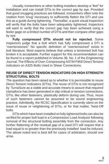
Usually, ironworkers or other bolting installers develop a “feel” for installation and can install DTIs to the correct gap by eye. Provided that good snugging practices are followed, ironworkers often note the rotation from ‘snug’ necessary to sufficiently flatten the DTI and use this as a guide during tightening. Thereafter, a quick visual inspection will verify that the bolts have been adequately tightened. Inspectors will want to verify that the correct gap has been achieved using a feeler gage on a limited number of DTIs and then compare other gaps by eye. Fully compressed DTIs should not be rejected. Some inspectors judge that a bolt which has fully compressed a DTI is “overtensioned.” No specific definition of “overtensioned” exists in bolt literature. Most experts believe that unless a tensioned bolt has broken it is acceptable. Further support for this recommendation can be found in a report published in Volume 36, No. 1 of the Engineering Journal, The Effects of Over-Compressing ASTM F959 Direct Tension indicators on A325 Bolts Used in Shear Connections.
REUSE OF DIRECT TENSION INDICATORS ON HIGH STRENGTHSTRUCTURAL BOLTSThe question has been raised as to whether it is permissible to reuseDirect Tension Indicators (DTIs). The reuse of DTIs is not recognized by TurnaSure as a viable and accurate means to assure that required clampforce has been generated in slip-critical or tension connections. DTIs, like other fasteners, plastically deform during use. Thus, reuse of such fasteners cannot be assumed to be sound engineering practice. Admittedly, the RCSC Specification is currently silent on the issue of reuse or retightening of DTIs, or for that matter, Twist-Off bolts. DTIs which have been installed on fully tightened bolts can also be verified for proper bolt load in a Compression Load Analyzer following removal of the structural bolting assembly from the connection. Any further flattening of the residual gap of a used DTI will require that a load equal to or greater than the previously installed load be induced. The above noted test is best left for cases of arbitration, should one arise.

BOLT TENSIONING USING PLAIN FINISH DTIs
METHOD #1
DTI Under the Bolt Head–Turn the Nut to Tension
For multiple plies and long bolts (typically large A490 bolts) thismethod will detect trapped bolts.
ASSEMBLY
Put the DTI under the bolt head with the bumps facing the undersideof the bolt head. Put a hardened washer under the nut. (Figure 5a)
With a short-slotted or oversized hole under the bolt head add a hardened flat washer between the DTI and the hole, and if the bolt is also an A490 larger than 1" the hardened washers must be at least 5/16" thick. (For a long-slotted hole, an external cover plate of sufficient size to completely cover the slot should be provided at a minimum of 5/16" thick.) (Figure 5b)
Check that the washer hole diameter conforms to the most currentrevision of ASTM F436 especially for sizes 1" and above, becauseprior to 2004 ASTM F436 allowed for washer I.D. considerably greaterthan the nominal diameter of the bolt and greater than a normal sizedhole in the connection itself. TurnaSure can assist in the procurementof correct washers. Normal sized holes either in a hardened washer orin the structural steel also helps prevent DTIs from dishing.
TENSIONING
Turn the nut until the gap between the bolt head and the DTI face isreduced to less than 0.015˝ in more than half of the entry spaces.When turning the nut, prevent the bolt head from spinning with a handwrench.
Figure 5a Figure 5b
Oversizehole
6INCH
BOLT TENSIONING USING PLAIN FINISH DTIs
METHOD #1
DTI Under the Bolt Head–Turn the Nut to Tension
For multiple plies and long bolts (typically large A490 bolts) this method will detect trapped bolts.
ASSEMBLYPlace the DTI under the bolt head with the bumps facing the undersideof the bolt head. Place a hardened F436 washer under the nut. (Figure 5a)
With a short-slotted or oversized hole under the bolt head add a hardened flat washer between the DTI and the hole, and if the bolt is also an A490 larger than 1” the hardened washers must be at least 5/16” thick. For a long-slotted hole, an external cover plate of sufficient size to completely cover the slot should be provided. (Figure 5b) See Table 6.1 of the RCSC Specification for detailed washer requirements.
Check that the washer hole diameter conforms to the most current revision of ASTM F436 especially for sizes 1” and above, because prior to 2004 ASTM F436 allowed for washer I.D. considerably greater than the nominal diameter of the bolt and greater than a normal sized hole in the connection itself. TurnaSure can assist in the procurement of correct washers. Normal sized holes either in a hardened washer or in the structural steel also helps prevent DTIs from dishing.
TENSIONING
Turn the nut until the gap between the bolt head and the DTI face is reduced to less than 0.015˝ in more than half of the entry spaces. When turning the nut, prevent the bolt head from spinning with a wrench.

7INCH
BOLT TENSIONING USING PLAIN FINISH DTIs (Continued)
METHOD #2
DTI Under the Nut–Turn the Nut to Tension
Use of this method saves the need for a hardened washer on stan-dard connection not involving multiple plies or large A490 bolts.
ASSEMBLY
Place the DTI under the nut with the bumps facing the nut. (Figure 6a)
With a short-slotted or oversized hole under the bolt head or nut, add ahardened flat washer, and, if the bolt is an A490 and larger than 1" thehardened washers must be at least 5/16" thick. (For a long-slotted hole, an external cover plate of sufficient size to completely cover the slotshould be provided at a minimum of 5/16" thick). (Figures 6b and 6c).
Note A: The new TurnaSure DTIs do not need hardened washers betweenthe nut and DTI. This assembly was for DTIs with the older design“straight-sided” protrusions (as depicted in Figures 12 and 13 on page 20).With the old design DTIs a hardened washer has to be used between thenut and DTI to achieve consistent assembly loads.
TENSIONING
Turn the nut until the gap between the nut and the DTI face is reducedto less than 0.005" in more than half of the entry spaces. When turn-ing the nut, prevent the bolt head from spinning with a hand wrench.
Figure 6a Figure 6b Figure 6c
Note A
Oversizehole
Note A: The new TurnaSure DTIs do not need hardened washers be-
tween an ASTM A563 DH nut and DTI. This assembly was for DTIs
with the older design “straight-sided” protrusions (as depicted in Fig-
ures 12 and 13 on page 20). With the old design DTIs a hardened
washer has to be used between the nut and STI to achieve consistentassembly loads.
BOLT TENSIONING USING PLAIN FINISH DTIs (Continued)
METHOD #2
DTI Under the Nut–Turn the Nut to Tension
Use of this method saves the need for a hardened washer on standardconnection not involving multiple plies or large A490 bolts.
ASSEMBLYPlace the DTI under the nut with the bumps facing the nut. (Figure 6a)
With a short-slotted or oversized hole under the bolt head or nut, add a hardened flat washer, and, if the bolt is an A490 and larger than 1” the hardened washers must be at least 5/16” thick. For a long-slotted hole, an external cover plate of sufficient size to completely cover the slot should be provided. (Figures 6b and 6c) See Table 6.1 of the RCSC Specification for detailed washer requirements.Note A: The new TurnaSure DTIs do not need hardened washers between an ASTM A563 DH nut and DTI. DTIs with the older design “straight-sided” protrusions as depicted in Figures 12 and 13 on page 20 would still require an F436 washer between the turned element and the DTI.
TENSIONING
Turn the nut until the gap between the nut and the DTI face is reducedto less than 0.005” in more than half of the entry spaces. When turning the nut, prevent the bolt head from spinning with a wrench.

BOLT TENSIONING USING PLAIN FINISH DTIs (End)
METHOD #3
DTI Under the Bolt Head–Turn the Bolt Head to Tension
Use this method if method #1 or #2 can not be used.
ASSEMBLY
Place the DTI under the bolt head with the bumps facing the bolthead. (Figure 7a)
With a short-slotted or oversized hole under the bolt head or nut, add ahardened flat washer, and, if the bolt is an A490 and larger than 1" thehardened washers must be at least 5/16" thick. (For a long-slotted hole, an external cover plate of sufficient size to completely cover the slotshould be provided at a minimum of 5/16" thick). (Figure 7b and 7c)
Note B: The new TurnaSure DTIs do not need hardened washers betweenthe bolt head and DTI. This assembly was for DTIs with the older design“straight-sided” protrusions (as depicted in Figures 12 and 13 on page 20).With the old design DTIs a hardened washer to be used between the bolt head and DTI to achieve consistent assembly loads.
TENSIONING
Turn the bolt head until the gap between the bolt head and the DTI isreduced to less than 0.005˝ in more than half of the spaces. Whenturning the bolt head, prevent the nut from spinning with a handwrench.
8INCH
Figure 7a Figure 7b Figure 7c
Note B
Oversizehole
BOLT TENSIONING USING PLAIN FINISH DTIs (End)
METHOD #3
DTI Under the Bolt Head–Turn the Bolt Head to Tension
Use of this method is typically done if method #1 or #2 can not be used or when box sections or other blind connections and/or when architectural considerations make use of this configuration desirable.
ASSEMBLYPlace the DTI under the bolt head with the bumps facing the bolt head. (Figure 7a)
With a short-slotted or oversized hole under the bolt head or nut, add a hardened flat washer, and, if the bolt is an A490 and larger than 1” the hardened washers must be at least 5/16” thick. For a long-slotted hole, an external cover plate of sufficient size to completely cover the slot should be provided. (Figure 7b and 7c) See Table 6.1 of the RCSC Specification for detailed washer requirements.
Note B: TurnaSure ’curved protrusion’ DTIs do not need hardened washers between the bolt head and DTI.
Turn the bolt head until the gap between the bolt head and the DTI is reduced to less than 0.005˝ in more than half of the spaces. When turning the bolt head, prevent the nut from spinning with a wrench.

BOLT TENSIONING USING COATED DTIs OR TYPE-3 WEATHERING STEEL DTIs
METHOD #1
DTI Under the Bolt Head–Turn the Nut to Tension
All DTIs should be assembled under the bolt head wherever possible. Assembly and tensioning should proceed as with “plain.”For galvanized and epoxy coated or weathering steel DTIs the gapbetween the bolt head and the DTI face should be reduced to lessthan 0.005" in more than half of the entry spaces. (Figure 8a)
*The use of flat hardened washers per the provisions of the RCSCSpecification varies with the bolt strength, hole size and yield strength ofconnected steel and tightening method. For example, with a short-slottedor oversized hole under the bolt head add a hardened flat washer betweenthe DTI and the hole, and, if the bolt is an A490 and larger than 1" the hardened washers must be at least 5/16" thick. (For a long-slotted hole, anexternal cover plate of sufficient size to completely cover the slot should beprovided at a minimum of 5/16" thick). (Figure 8b)
For bridge applications see INSTALLATION INSTRUCTIONS FORBRIDGE APPLICATIONS PER AASHTO, found on the inside backcover.
9INCH
Figure 8a Figure 8b
Oversizehole
BOLT TENSIONING USING COATED DTIs OR TYPE-3WEATHERING STEEL DTIs
METHOD #1
DTI Under the Bolt Head–Turn the Nut to Tension
DTIs are most often assembled under the bolt head wherever possible. Assembly and tensioning should proceed as with “plain.” For galvanized and epoxy coated or weathering steel DTIs the gap between the bolt head and the DTI face should be reduced to less than 0.005” in more than half of the entry spaces. (Figure 8a)
*The use of flat hardened washers per the provisions of the RCSC Specification varies with the bolt strength, hole size and yield strength of connected steel and tightening method. Please refer to Table 6.1 of the RCSC Specification for Structural Joints Using High-Strength Bolts for detailed washer and plate washer requirements.
For bridge applications see INSTALLATION INSTRUCTIONS FOR BRIDGE APPLICATIONS PER AASHTO, found on the inside back cover of this manual.

BOLT TENSIONING USING COATED DTIs OR TYPE-3WEATHERING STEEL DTIs (Continued)
METHOD #2
DTI Under the Nut–Turn the Nut to Tension, or
METHOD #3
DTI Under the Bolt Head–Turn the Bolt Head to Tension
These installation arrangements should be used when method #1cannot be used. The DTIs should be compressed to a gap of lessthan 0.005" in more than half of the entry spaces. (Figures 9a and 10a)
The use of flat hardened washers per the provisions of the RCSCSpecification varies with the bolt strength, hole size, and yield strength ofconnected steel and tightening method. For example, with a short-slottedor oversized hole under the bolt head or nut add a hardened flat washer,and, if the bolt is an A490 and larger than 1" the hardened washers mustbe at least 5/16" thick. (For a long-slotted hole, an external cover plate ofsufficient size to completely cover the slot should be provided at a minimum of 5/16" thick). (Figures 9b, 9c, 10b and 10c)
Check that the washer hole diameter conforms to the most current revision of ASTM F436 especially for sizes 1" and above, because priorto 2004 ASTM F436 allowed for washer I.D considerably greater thanthe nominal diameter of the bolt and greater than a normal sized holein the connection itself. TurnaSure can assist in the procurement of correct washers. Normal sized holes either in a hardened washer or inthe structural steel also helps prevent DTIs from dishing.
10INCH
Figure 9b
Figure 9a Figure 9c
Note C
Oversizehole
BOLT TENSIONING USING COATED DTIs OR TYPE-3WEATHERING STEEL DTIs (Continued)
METHOD #2
DTI Under the Nut–Turn the Nut to Tension, or
METHOD #3
DTI Under the Bolt Head–Turn the Bolt Head to Tension
The DTIs should be compressed to a gap of less than 0.005” in more than half of the entry spaces. (Figures 9a and 10a)
The use of flat hardened washers per the provisions of the RCSC Specification varies with the bolt strength, hole size, and yield strength of connected steel and tightening method. Please refer to Table 6.1 of the RCSC Specification for Structural Joints Using High-Strength Bolts for detailed washer and plate washer requirements. (Figures 9b, 9c, 10b and 10c)
Check that the washer hole diameter conforms to the most current revision of ASTM F436 especially for sizes 1” and above, because prior to 2004 ASTM F436 allowed for washer I.D considerably greater than the nominal diameter of the bolt and greater than a normal sized hole in the connection itself. TurnaSure can assist in the procurement of correct washers. Normal sized holes either in a hardened washer or in the structural steel ensures that the DTI is properly supported and prevents dishing.

BOLT TENSIONING USING COATED DTIs OR TYPE-3WEATHERING STEEL DTIs (End)
Note C: The new TurnaSure DTIs do not need hardened washersbetween the nut and DTI. This assembly was for DTIs with the olderdesign “straight-sided” protrusions (as depicted in Figures 12 and 13 onpage 20). With the old design DTIs a hardened washer has to be usedbetween the nut and DTI to achieve consistent assembly loads.
11INCH
Figure 10b
Figure 10a Figure 10c
Note C
Oversizehole
Note C: The new TurnaSure DTIs do not need hardened wash-
ers between an ASTM A563 DH nut and DTI. This assembly
was for DTIs with the older design “straight-sided” protrusions
(as depicted in Figures 12 and 13 on page 20). With the old
design DTIs a hardened washer has to be used between the nut
and DTI to achieve constant assembly loads.
BOLT TENSIONING USING COATED DTIs OR TYPE-3WEATHERING STEEL DTIs (End)
Note C: TurnaSure ‘curved protrusion’ DTIs do not need hardened washers between the nut and DTI. DTIs with the older design “straight-sided” protrusions as depicted in Figures 12 and 13 on page 20 would still require an F436 washer between the turned element and the DTI.

12INCH
RECOMMENDED BOLT INSTALLATION PROCEDURE
Step 1
Bring the members to be joinedtogether and align the holes withdrift pins. (Bolts should not be usedas drift pins to achieve alignment.)
Step 2
Fill the remaining holes with high-strength bolts, nuts, washers, andDTIs of the correct size and grade.Partially tension the bolts to snugthe connection. Partial tension is evi-denced by slight, but visible, flatten-ing of the DTI protrusions. At thispoint there will be as much as 50% ofthe minimum specified tension in thebolt. This amount of tension shouldbe sufficient to produce a snug con-nection. Work from the center of theconnection to the free edges.
No Tension Partial Tension“Snug”
Step 2
Fill the remaining holes with high strength bolts, nuts, washers, and DTIs of the correct size and grade. Partially tension the bolts to snug the connection. Partial tension is evidenced by slight, but visible, flattening of the DTI protrusions. At this point there will be as much as 50% of the minimum specified tension in the bolt. This amount of tension should be sufficient to produce a snug connection. Work from the center (or a point of intimate contact) of the connection to the free edges.
13INCH
Step 3
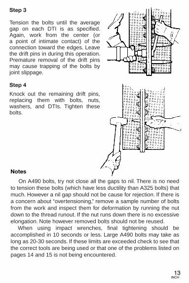
Tension the bolts until the averagegap on each DTI is as specified.Again, work from the center of theconnection toward the edges. Leavethe drift pins in during this operation.Premature removal of the drift pinsmay cause trapping of the bolts byjoint slippage.
Step 4
Knock out the remaining drift pins,replacing them with bolts. Tightenthese bolts.
Notes
On A490 bolts, try not close all the gaps to nil. There is no needto tension these bolts (which have less ductility than A325 bolts) thatmuch. However a nil gap should not be cause for rejection. If there isa concern about “overtensioning,” remove a sample number of boltsfrom the work and inspect them for deformation by running the nutdown to the thread runout. If the nut runs down there is no excessiveelongation. Note however if the removed bolt is A490 or galvanizedA325 it cannot be reused.
When using impact wrenches, final tightening should be accom-plished in 10 seconds or less. Large A490 bolts may take as long as20 seconds. If these limits are exceeded check to see that the cor-rect tools are being used or that one of the problems listed on pages14 and 15 is not being encountered.
Step 3
Tension the bolts until the average gap on each DTI is as specified. Again, work from the center (or a point of intimate contact) of the connection toward the edges. Leave the drift pins in during this operation. Premature removal of the drift pins may cause trapping of the bolts by joint slippage.
Step 4
Knock out the remaining drift pins, replacing them with bolts, nuts, washers, and DTIs. Tighten these bolts.
On A490 bolts, try not close all the gaps to nil. There is no need to tension these bolts (which have less ductility than A325 bolts) that much. However a nil gap should not be cause for rejection. If there is a concern about “overtensioning,” remove a sample number of bolts from the work and inspect them for deformation by running the nut down to the thread runout. If the nut runs down there is no excessive elongation. Note however removed bolts should not be reused. When using impact wrenches, final tightening should be accomplished in 10 seconds or less. Large A490 bolts may take as long as 20-30 seconds. If these limits are exceeded check to see that the correct tools are being used or that one of the problems listed on pages 14 and 15 is not being encountered.

14INCH
PROBLEMS COMMONLY ENCOUNTERED WHENTENSIONING BOLTS
Dry or Rusty Threads or Nut Faces–Usually caused by poor storageconditions, dry or rusty bolts, nuts or washers should not be permit-ted. Ideally nuts, bolts, washers and DTIs should be kept in dry stor-age and their containers not opened until immediately before use.Rust significantly increases the amount of torque required to tensiona bolt. Ideally nuts should be wax dipped before use, particularly onlarge A490 bolts. Lubricant on the face of the nut is very desirable. Ifit is necessary to lubricate bolts at the site at the time of installationCastrol Industrial STICK WAX Lubricant is recommended. It is avail-able from many sources including TurnaSure LLC. The necessity ofadequate lubricant to achieve the desired level of bolt preten-sion cannot be over-emphasized.
Galvanized Nuts and Bolts–Hot dipped galvanized nuts should havethreads tapped oversize after galvanizing. Mechanically galvanizednuts are tapped before galvanizing. The nuts should be dipped in awax lubricant, preferably with dye so the lubricant can be seen. Aturn test, which is mandatory and described in A325, should be per-formed on two samples from every lot combination shipped to assurethat the bolts can be tensioned without either seizure or stripping thenut threads.
Damaged Threads–Usually caused by forcing the bolt through mis-aligned holes, this will cause the nut to “freeze.”
Trapped Bolts–Usually caused by slippage in the joint as a result ofremoval of drift pins before enough bolts have been tensioned to pre-vent slippage. Trapped bolts cannot develop tension along theirentire length.
Bolts Too Long–The nut runs up against the thread runout before thebolt is properly tensioned.
Recommended Nuts–Nuts with less than 175,000psi proof stressmay gall, are prone to stripping and generally require more torque totension bolts. Nuts manufactured to ASTM A563 DH are recom-mended when bolts are to be tensioned.
PROBLEMS COMMONLY ENCOUNTERED WHENTENSIONING BOLTS
Dry or Rusty Threads or Nut Faces–Usually caused by poor storage conditions or passage of time between snugging of bolts and start-up of final tensioning. Dry or rusty bolts, nuts, or washers should not be permitted. Ideally nuts, bolts, washers, and DTIs should be kept in dry storage and their containers not opened until immediately before use. Rust significantly increases the amount of torque required to tension a bolt. Ideally nuts should be wax dipped before use, particularly on large A490 bolts. Lubricant on the face of the nut is very desirable. If it is necessary to lubricate bolts at the site at the time of installation Castrol Industrial STICK WAX Lubricant is recommended. It is available from many sources including TurnaSure LLC. The necessity of adequate lubricant to achieve the desired level of bolt pretension cannot be over-emphasized.
Galvanized Nuts and Bolts–Hot dipped galvanized nuts should have threads tapped oversize after galvanizing. Mechanically galvanized nuts are tapped before galvanizing. The nuts should be dipped in a wax lubricant, preferably with dye so the lubricant can be seen. A Rotational Capacity test, which is mandatory and described in A325, should be performed on samples from every lot combination shipped to assure that the bolts can be tensioned without either seizure or stripping the nut threads.
Damaged Threads–Usually caused by forcing the bolt through misaligned holes, this will cause the nut to “freeze.”
Trapped Bolts–Usually caused by slippage in the joint as a result of not using or removal of drift pins before enough bolts have been tensioned to prevent joint slippage. Trapped bolts cannot develop tension along their entire length.
Bolts Too Long–The nut runs up against the thread runout before the bolt is properly tensioned or so little thread remains within the grip that excessive torque is needed as bolts stretch concentrates in the threaded portion. (>3 thread stick-out from the nut face is inadvisable.)
Recommended Nuts–Nuts with less than 175,000psi proof stress may gall, are prone to stripping and generally require more torque to tension bolts. Heavy Hex nuts manufactured to ASTM A563 DH are recommended when bolts are to be tensioned.

15INCH
PROBLEMS COMMONLY ENCOUNTERED WHEN TIGHTENINGBOLTS (Continued)
Omission of Hardened Washers under the Turned Element–Hardened washers are not required by the RCSC Specification forall high-strength bolt installations where tensioning is required.However, the use of hardened washers under the turned elementsignificantly reduces the torque required to tension a bolt and is rec-ommended by TurnaSure LLC whether DTIs are used or not.Oversized Hardened Washer ID–Above 7/8", because ASTM F436allows a washer I.D. 1/8" greater than the diameter of the bolt, engi-neers may wish to consider “special” ASTM F436 hardened washerswith a smaller inside diameter consistent with a “normal size” hole.Hot Forged Bolts–Hot forged bolts must be free of die fins, burrs andexcessive swelling under the bolt heads which might prevent DTIsfrom properly contacting the washer face of the bolt. If necessary, toavoid this condition consider installing the DTI under the nut.Oversized Holes–Hardened washers are required to cover oversized andslotted holes. Requirements are spelled out in the RCSC Specification.A490 bolts larger than 1" require 5/16" thick washers, which are neces-sary to prevent the dishing of DTIs as well as the washer.
PROBLEMS COMMONLY ENCOUNTERED WHEN TIGHTENINGBOLTS (Continued)
Omission of Hardened Washers under the Turned Element– Hardened washers are not required by the RCSC Specification for all high-strength bolt installations where tensioning is required. However, the use of hardened washers under the turned element significantly reduces the torque required to tension a bolt and is recommended by TurnaSure LLC whether DTIs are used or not.
Oversized Hardened Washer ID–Above 7/8”, because ASTM F436 allows a washer I.D. 1/8” greater than the diameter of the bolt, engineersmay wish to consider “special” ASTM F436 hardened washers with a smaller inside diameter consistent with a “normal size” hole.
Hot Forged Bolts–Hot forged bolts must be free of die fins, burrs and excessive swelling under the bolt heads which might prevent DTIs from properly contacting the washer face of the bolt. If necessary, to avoid this condition consider installing the DTI under the nut.
Oversized Holes–Hardened washers are required to cover oversized and slotted holes. Requirements are spelled out in Table 6.1 of the RCSC Specification. Use of DTIs does not relieve the contractor of the obligation to use hardened or plate washers when otherwise required to do so by the RCSC.

16INCH
AIR-TOOL SELECTION AND PERFORMANCE
Air driven impact wrenches are the prevalent tool for installinghigh-strength bolts. These wrenches require between 25 and 120 cu.ft./min. of air at a pressure of 100psi, at the tool, while running, todeliver a particular torque. The torque required to install a high-strength bolt to the correct tension varies with the size and grade ofthe bolt, and with the bolt and nut thread condition. There are nospecific relationships between torque and tension.
Assuming the wrench is of adequate size, if problems areencountered in compressing DTIs within the time span noted, checkthe equipment for:
• Insufficient air pressure at the compressor.• Too many tools running at one time.• Too long an air line, or leaks in the air line.• Blockage of the inlet or outlet filter on the tool.• Broken tool.
If the tool is merely sluggish, blow it out with solvent to clean itand relubricate it with a light oil, SAE 5 or 10.
The chart below gives a rough guide to the suitable tool, basedon our field experience.
Bolt Size Chicago Ingersoll Norbar CLECOA325 A490 Pneumatic Rand
5/8" – 610/6041 2934/2906 PT500 WS21103/4" – 610/6500 2934/2920 PT1000 WS21107/8" 3/4" 611/6060 2940/2920 PT1000 WS2110
1" 7/8" 6120/6110 2950/2934 PT1500 WS2120
11/8" 1" 6120/6110 2950/2940 PT2000 WS2120
11/4" 11/8" 6210*/614 5980/2940 PT6/PT2000 –
13/8" 11/4" 614* 5980/2940 PT7/PT4500 –
11/2" – 614* 5980/2940 PT7/PT4500 –
*Only if the bolt and nut are well lubricated.
When tensioning large A490 bolts, hydraulic torque wrenchesshould be considered as an alternative to air driven impact wrenches.
AIR-TOOL SELECTION AND PERFORMANCE
Air driven impact wrenches are frequently used for installing high-strength bolts. These wrenches require between 25 and 120 cu. ft./min. of air at a pressure of 100psi, at the tool, while running, to deliver a particular torque. The torque required to install a high-strength bolt to the correct tension varies with the size and grade of the bolt, and with the bolt and nut thread condition. There are no specific relationships between torque and tension.
Assuming the wrench is of adequate size, if problems are encountered in compressing DTIs within the time span noted, check the equipment for: •Insufficientairpressureatthecompressor. •Toomanytoolsrunningatonetime. •Toolonganairline,orleaksintheairline. •Blockageoftheinletoroutletfilteronthetool. •Brokentool. If the tool is merely sluggish, blow it out with solvent to clean it and relubricate it with a light oil, SAE 5 or 10.
The chart below gives a rough guide to the suitable tool, based on ourfieldexperience.
16INCH
AIR-TOOL SELECTION AND PERFORMANCE
Air driven impact wrenches are the prevalent tool for installinghigh-strength bolts. These wrenches require between 25 and 120 cu.ft./min. of air at a pressure of 100psi, at the tool, while running, todeliver a particular torque. The torque required to install a high-strength bolt to the correct tension varies with the size and grade ofthe bolt, and with the bolt and nut thread condition. There are nospecific relationships between torque and tension.
Assuming the wrench is of adequate size, if problems areencountered in compressing DTIs within the time span noted, checkthe equipment for:
• Insufficient air pressure at the compressor.• Too many tools running at one time.• Too long an air line, or leaks in the air line.• Blockage of the inlet or outlet filter on the tool.• Broken tool.
If the tool is merely sluggish, blow it out with solvent to clean itand relubricate it with a light oil, SAE 5 or 10.
The chart below gives a rough guide to the suitable tool, basedon our field experience.
Bolt Size Chicago Ingersoll Norbar CLECOA325 A490 Pneumatic Rand
5/8" – 610/6041 2934/2906 PT500 WS21103/4" – 610/6500 2934/2920 PT1000 WS21107/8" 3/4" 611/6060 2940/2920 PT1000 WS2110
1" 7/8" 6120/6110 2950/2934 PT1500 WS2120
11/8" 1" 6120/6110 2950/2940 PT2000 WS2120
11/4" 11/8" 6210*/614 5980/2940 PT6/PT2000 –
13/8" 11/4" 614* 5980/2940 PT7/PT4500 –
11/2" – 614* 5980/2940 PT7/PT4500 –
*Only if the bolt and nut are well lubricated.
When tensioning large A490 bolts, hydraulic torque wrenchesshould be considered as an alternative to air driven impact wrenches.
When tensioning large A490 bolts, hydraulic torque wrenches should be considered as an alternative to air driven impact wrenches. Quiet and powerful electric operated installation wrenches are increasingly popularforinstallationofheavyhexstructuralbolts.Contactyourboltdistributor for information on how to lease or purchase these tools.

17INCH
CHECKING FOR CONFORMANCE TO SPECIFICATIONS
Identification and Certification
Inspectors should check that all fastener components conformto applicable ASTM standards before use. Manufacturers’ marksshould be clearly identifiable on all fasteners. Where required, test certificates should accompany product to the job site. Bolt certificates should state tensile strength and hardness. Nut certificates should state hardness and proof-load. Hardened washercertificates should identify that they are in a hardness range of 38 to45 Rockwell C. DTIs should be marked to identify the lot number,manufacturer and Type (325 or 490).
TurnaSure LLC DTIs are carefully tested throughout the manu-facturing process utilizing statistical process control procedures. Thefinished product is tested by an independent accredited laboratory inA Digital Compression Load Analyzer with a dial gage.
Certification of testing, according to ASTM F959 requires up to 29 pieces per lot, without failure, in the as-shipped condition, coated or uncoated, be tested, following ASTM F1470 Guide forFastener Sampling.
Laboratory duplication of the ASTM product performance testby the user should not be required. There should be no attempt toreproduce the product performance test in the field. Instead, the fol-lowing test of the DTI and bolt/nut/washer assembly in a bolt tensioncalibrator is suggested. This will assist the user in qualifying all of thecomponents, and verifying their compatibility.
CHECKING FOR CONFORMANCE TO SPECIFICATIONS
Identification and Certification
Inspectors should verify that all fastener components conform to applicable ASTM standards before use. Manufacturer Identification marks should be clearly visible on all fasteners. Where required, test certificates should accompany product to the job site. Bolt certificates should state tensile strength and hardness. Nut certificates should state hardness and proof-load. Hardened washer certificates should identify that they are in a hardness range of 38 to 45 Rockwell C. DTIs should be marked to identify the lot number, manufacturer, and Type (325 or 490).
TurnaSure LLC DTIs are carefully tested throughout the manufacturing process utilizing statistical process control procedures. The finished product is tested by an independent accredited laboratory in A Digital Compression Load Analyzer with a dial gage.
Certification of testing, according to ASTM F959 requires up to 29 pieces per lot, without failure, in the as-shipped condition, coated or uncoated, be tested, following ASTM F1470 Guide for Fastener Sampling.
Laboratory duplication of the ASTM product performance test by the user should not be required. There should be no attempt to reproduce the product performance test in the field. Instead, the following test of the DTI and bolt/nut/washer assembly in a bolt tension calibrator is suggested. This will assist the user in qualifying all of the components as suitable for use in the condition in which they reached the project site, and also verifies that the tools to be used for bolt tightening are of adequate capacity. Lastly, it provides a means of assurance that the ironworkers or bolting installers are familiar with the bolting method and can demonstrate mastery of the skills necessary to install structural bolts in accordance with the project requirements.

18INCH
Figure 5
Tension the bolt to the minimum required bolt tension and checkthat the applicable feeler gage enters at least the proper number ofspaces (tension and spaces given in Table II). A 0.015" feeler gageis used when an uncoated DTI is installed under the bolt head andthe nut is turned, Method #1. A 0.005" feeler gage is used withMethods #2 and #3 and with coated DTIs in any arrangement. Theload should be increased on the calibrator as smoothly as possibleso as to avoid “fallback” where the load cell “bleeds off” and the cal-ibrator starts to show a lower load than the actual bolt load. At thispoint the assembly has demonstrated the ability to reach the desiredtension prior to compression of the number of bumps which arerequired to be compressed in the work.
Field Verification Test for Bolt Assembly Performance
Assemble the bolt, nut, washer and DTI in a bolt tension cali-brator as shown in Figure 5.
Verify that the tension calibrator has been certified and calibrat-ed within the last year. The certification document provides a trace-able comparison of the calibrator’s readings with those establishedby the U.S. National Institute of Standards and Technology or thestandards agency having jurisdication in the construction location.Apply any noted variations to the load readings during testing on thecalibrator.
Field Pre-Installation Verification Test
Assemble the bolt, nut, washer, and DTI in a bolt tension calibratoras shown in Figure 5. Verify that the tension calibrator has been certified and calibrated within the last year. The certification document provides a traceable comparison of the calibrator’s readings with those established by the U.S. National Institute of Standards and Technology or the standards agency having jurisdication in the construction location. Apply any noted variations to the load readings during testing on the calibrator.
18INCH
Figure 5
Tension the bolt to the minimum required bolt tension and checkthat the applicable feeler gage enters at least the proper number ofspaces (tension and spaces given in Table II). A 0.015" feeler gageis used when an uncoated DTI is installed under the bolt head andthe nut is turned, Method #1. A 0.005" feeler gage is used withMethods #2 and #3 and with coated DTIs in any arrangement. Theload should be increased on the calibrator as smoothly as possibleso as to avoid “fallback” where the load cell “bleeds off” and the cal-ibrator starts to show a lower load than the actual bolt load. At thispoint the assembly has demonstrated the ability to reach the desiredtension prior to compression of the number of bumps which arerequired to be compressed in the work.
Field Verification Test for Bolt Assembly Performance
Assemble the bolt, nut, washer and DTI in a bolt tension cali-brator as shown in Figure 5.
Verify that the tension calibrator has been certified and calibrat-ed within the last year. The certification document provides a trace-able comparison of the calibrator’s readings with those establishedby the U.S. National Institute of Standards and Technology or thestandards agency having jurisdication in the construction location.Apply any noted variations to the load readings during testing on thecalibrator.
Tension the bolt to the minimum required bolt tension and check that the applicable feeler gage enters at least the proper number of spaces (tension and spaces given in Table II). A 0.015” feeler gage is used when an uncoated DTI is installed under the bolt head and the nut is turned, Method #1. A 0.005” feeler gage is used with Methods #2 and #3 and with coated DTIs in any arrangement. The load should be increased on the calibrator as smoothly as possible so as to avoid “fallback” where the load cell “bleeds off” and the calibrator starts to show a lower load than the actual peak bolt load. At this point the assembly has demonstrated the ability to reach the desired tension prior to compression of the number of bumps which are required to be compressed in the work.

19INCH
Next tension the bolt until the point where the feeler gagerefuses to enter the number spaces in Table II. The tension in the boltas measured by the calibrator must be less than the minimum ten-sile strength of the bolt. At this point the assembly has demonstrat-ed the ability to compress the bumps to the gap required in the workwithout exceeding the minimum tensile strength of the bolt.
Table II
TYPE 325Minimum
Nominal Minimum BoltBolt Bolt Tensile
Diameter Tension Strength DTI Feeler-Gage Feeler-Gage(in.) (kips) (kips) Spaces Entries Refusals1/2" 12 17 4 2 35/8" 19 27 4 2 33/4" 28 40 5 3 37/8" 39 55 5 3 31" 51 73 6 3 4
1-1/8" 56 80 6 3 41-1/4" 71 102 7 4 41-3/8" 85 121 7 4 41-1/2" 103 148 8 4 5
TYPE 490Minimum
Nominal Minimum BoltBolt Bolt Tensile
Diameter Tension Strength DTI Feeler-Gage Feeler-Gage(in.) (kips) (kips) Spaces Entries Refusals1/2" 15 21 5 3 35/8" 24 34 5 3 33/4" 35 50 6 3 47/8" 49 69 6 3 41" 64 91 7 4 4
1-1/8" 80 114 7 4 41-1/4" 102 145 8 4 51-3/8" 121 173 8 4 51-1/2" 148 211 9 5 5
For bridge applications see INSTALLATION INSTRUCTIONS FORBRIDGE APPLICATIONS PER AASHTO, found on the inside backcover.
If air-driven impact wrenches are being used during this test, caution is advised, as excessive vibration can sometimes damage the bolt tension calibrator and/or make it impossible to read the gage accurately.

DTI IDENTIFICATION MARKINGS
TRADEMARK
The trademark of TurnaSure LLC is shown on the cover of this booklet. DTIs marked with it have been manufactured by TurnaSure LLC.
GRADE AND SIZE
Each DTI is marked with a series of numbers. “325” signifies theDTI is for use with A325 bolts, “490” for A490 bolts. DTIs for use withType 3 weathering steel A325 bolts are marked “325-3”. Such DTIsare the newer versions that are produced from a weathering steeland thus do not require epoxy coating to protect them from exces-sive corrosion. Size is not marked on 325 or 490 DTIs, however theycan be identified by the close fit over the bolt.
LOT NUMBER
For purposes of absolute traceability ASTM requires each DTIbe marked with a lot number. The lot number will take the form of aletter followed by either one or more numbers.
Figure 11 illustrates the new and improved 325 DTI design.
Figure 11
Figure 12 Figure 13
Older designs look like Figures 12 & 13.
20INCH
DTI IDENTIFICATION MARKINGS
TRADEMARK The trademark of TurnaSure LLC is shown on the cover of this booklet. DTIs marked with it have been manufactured by TurnaSure LLC.
GRADE AND SIZE Each DTI is marked with a series of numbers. “325” signifies the DTI is for use with A325 bolts, “490” for A490 bolts. DTIs for use with Type 3 weathering steel A325 bolts are marked “325-3”. Such DTIs are the newer versions that are produced from a weathering steel and thus do not require epoxy coating to protect them from excessive corrosion. Size is not marked on Type 325 or Type 490 DTIs, however they can be identified by the close fit over the bolt.
LOT NUMBER For purposes of absolute traceability ASTM requires each DTI be marked with a lot number. The lot number will take the form of a letter followed by either one or more numbers.
Figure 11 illustrates the new and improved Type 325 DTI design.

INSTALLATION INSTRUCTIONS FOR BRIDGE APPLICATIONSPER AASHTO
The AASHTO LRFD Bridge Construction Specifications 3rd Edition (inclusive of Interim Revisions thru 2014), provide detailed instructions for Pre-Installation Verification testing and Bolting Installation using DTIs in Section 11 Part 11.5.6.4.7. The major difference between the instructions given in the AASHTO Specifications and those presented in this manual is the requirement that the AASHTO gap closure requirement is 0.005˝ for installation of plain finish DTIs under the bolt head, not 0.015˝ as stated in this Installation Manual. The 0.015˝ gap was selected as convenient for building installation where plain DTIs are typically installed within an enclosed structure where bolted connections are not subject to weathering. As tests have shown that paint systems typically used on bridges will “bridge” a gap of 0.005˝ successfully, but may not “bridge” a gap of 0.015˝, and since many states specify galvanized fasteners, AASHTO has set a maximum gap of 0.005˝ for “plain” and “coated” DTIs in all connections. TurnaSure LLC does not recommend complete flattening of Type 490 DTIs on uncoated A490 bolts to the point where a 0.005” gage is refused in all spaces, as this risks bolt breakage during installation. Preferrably at least one space remains open, although complete flattening in all spaces should not be cause for rejection. Note, Article 11.5.6.4.7 has two parts, 7a Verification, and 7b Installation and an accompanying Commentary. Verification assures that before the DTI is compressed to an average gap of 0.005˝ the tension in the bolt will be at least 1.05 times the minimum required bolt tension. It also assures that when the DTI is all but completely compressed, the bolt will not have excessive permanent inelastic deformation. In the event of a conflict between the Instructions provided herein, and those in a reference standard, the instructions contained within this manual shall take precedence. All Pre-Installation Verification tests should be performed with the fasteners configured in the bolt tension calibrator just as they are to be configured when installed in the structural steel.
®
Turn
aS
ure
LLC
InternationalHeadquarters
Phone:215-750-1300
Fax:215-750-6300
340E
.Maple
Avenue,S
uite206
Website:w
ww
.turnasure.comLanghorne,PA
19047