doordarshan patna summer training
TRANSCRIPT

AMAL ROSHAN NIT CALICUT
2 0 1 3
SUBMITTED TO- SUBMITTED BY-
MD. YUSUF SIR AMAL ROSHANMD. YUSUF SIR AMAL ROSHANMD. YUSUF SIR AMAL ROSHANMD. YUSUF SIR AMAL ROSHAN
MAHESH LEPCHA SIR NIMAHESH LEPCHA SIR NIMAHESH LEPCHA SIR NIMAHESH LEPCHA SIR NIT CALICUTT CALICUTT CALICUTT CALICUT (2011(2011(2011(2011----15)15)15)15)
SERIAL NO SERIAL NO SERIAL NO SERIAL NO ---- 08080808
AMAL ROSHAN NIT CALICUT
AMAL ROSHAN NIT CALICUT
DECLARATION
I HEREBY DECLARE THAT WORK ENTITLED “SUMMER
TRAINING REPORT”, SUBMITTED TOWARDS COMPLETION
OF SUMMER TRAINING AFTER 2ND YEAR OF B.TECH
(ECE) AT NATIONAL INSTITUTE OF TECHNOLOGY (NIT)
CALICUT , COMPRISES OF MY ORIGINAL WORK PURSUED
UNDER THE GUIDANCE OF MR. MAHESH LEPCHA. THE
RESULTS EMBODIED IN THIS REPORT HAVE NOT BEEN
SUBMITTED TO ANY OTHER INSTITUTE OR UNIVERSITY
FOR ANY AWARD.
AMAL ROSHAN
B.TECH(2ND YEAR)
AMAL ROSHAN NIT CALICUT
AMAL ROSHAN NIT CALICUT
CERTIFICATE
THIS IS TO CERTIFY THAT MR. AMAL ROSHAN, A
STUDENT OF B.TECH, FROM NATIONAL INSTITUTE OF
TECHNOLOGY, CALICUT COMPLETED A 4 WEEK
VOCATIONAL SUMMER TRAINING PROGRAM AT
DOORDARSHAN PATNA, UNDER MY GUIDANCE AND
DIRECTION.
SIGNATURE OF THE GUIDE
AMAL ROSHAN NIT CALICUT

AMAL ROSHAN NIT CALICUT
ACKNOWLEDGEMENT
ON THE VERY OUTSET OF THIS REPORT, I WOULD LIKE TO EXTEND MY
SINCERE & HEARTFELT OBLIGATION TOWARDS ALL THE PERSONAGES
WHO HAVE HELPED ME IN THIS ENDEAVOR. WITHOUT THEIR ACTIVE
GUIDANCE, HELP, COOPERATION & ENCOURAGEMENT, I WOULD NOT
HAVE MADE HEADWAY IN THE PROJECT.
FIRST AND FOREMOST, I WOULD LIKE TO EXPRESS MY SINCERE
GRATITUDE TO MY PROJECT GUIDE, MR. MAHESH LEPCHA. I WAS
PRIVILEGED TO EXPERIENCE A SUSTAINED ENTHUSIASTIC AND
INVOLVED INTEREST FROM HIS SIDE. THIS FUELLED MY ENTHUSIASM.
I WOULD ALSO LIKE TO THANK MD. YUSUF SIR WHO ALWAYS GUIDED ME
IN RIGHT DIRECTION.
THIS WAS A TRULY AMAZING EXPERIENCE WHICH PROVIDED ME LIVE
EXPERIENCE OF AND WORKING METHODOLOGY OF VARIOUS EQUIPMENTS.
THANKING YOU.
AMAL ROSHAN
AMAL ROSHAN NIT CALICUT

AMAL ROSHAN NIT CALICUT
AMAL ROSHAN NIT CALICUT
AMAL ROSHAN NIT CALICUT
CONTENTS
• DOORDARSHAN HISTORY
• DOORDARSHAN PATNA
• FUNDAMENTALS OF MONOCHROME AND COLOUR TV
• COLOUR COMPOSITE VIDEO SIGNAL
• TV STUDIO
• TV CAMERA
• STUDIO LIGHTING
• MICROPHONE
• CABLES AND CONNECTORS
• PRINCIPLES OF VTR
• VISION MIXING
• TV TRANSMITTER
• EARTH STATION
• SATELLITE COMMUNICATION
• DTH
AMAL ROSHAN NIT CALICUT
AMAL ROSHAN NIT CALICUT
DOORDARSHAN HISTORY
Prasar Bharati is a statutory autonomous body established under the Prasar Bharati Act and
came into existence on 23.11.1997. It is the Public Service Broadcaster of the country. The
objectives of public service broadcasting are achieved in terms of Prasar Bharati Act through All
India Radio and Doordarshan, which earlier were working as media units under the Ministry
of I&B and since the above said date became constituents of Prasar Bharati
15 September, 1959 was the first day when the transmission of television
programme begin in India at a make shift studio in the All India Radio building. Pramita
Puri was the first announcer who started the programme with “shehnai recital' of Ustaad
Bismillah Khan. The programme was transmitted in a radius of 25 kilometers with a
small transmitter. From Black & White to becoming color in 1982 to digital telecast in
2004, the public broadcaster has grown with tune of time.
National telecasts were introduced in 1982. In the same year, color TV was introduced in the Indi
an market with the live telecast of the Independence Day speech by then prime minister Indira
Gandhi on 15 August 1982, followed by the 1982 Asian Games being held in Delhi. Now
more than 96 percent of the Indian population can receive Doordarshan (DD National)
programmes through a network of nearly 1400
terrestrial transmitters and about 46 Doordarshan studios produce TV
programs today.
SIGNIFICANT MILESTONES ACHIEVED WERE
• Launch of international channel -D India (14 March 1995)
• Formation of Prasar Bharti (Broadcasting Corporation of India) (23 November 1997)
• Launch of sports channels DD sports (18 March 1999)
• Launch of enrichment/ culture channel - DD Bharti (26 January 2002)
• Launch of 24 hours news channel - DD News (3 November 2002)
• Launch of free to air Direct – To – Home Service DD Direct+ (16 December 2004)
DTH –
DTH i.e. the direct to home telecast. This Service has been launched by DELHI
DOORDARSHAN from earth station KU Band Todapur, Delhi. It works on KU Band
width (11.7-13 GHz) This
service transponds perfectly up to 200 channels. Doordarshan’s DTH service is available
at National satellite, INSAT 4B.
AMAL ROSHAN NIT CALICUT
AMAL ROSHAN NIT CALICUT
DOORDARSHAN KENDRA:: PATNA AT A GLANCE
oordarshan Kendra, Patna was
inaugurated on the 13th October
1990 with an interim set up
converting a Government
Quarter located at Chhajubagh, Patna.
Adjacent area was demarcated for the
construction of a full-fledged studio.
The new studio building with all the
modern equipments and accessories
was finally inaugurated on the 15th
March 1996.
nitially, Doordarshan Kendra, Patna
started its programme having one
hour duration with the news
bulletin in Hindi for a duration of 15
minutes. A five-minute Urdu News
Bulletin was subsequently started in
May 1992 which was further increased
to 10 minutes in the year 1993. A
Satellite Link with all the Transmitters
of Bihar was established in 1994. The
commercial service at this Kendra was
introduced in the year 1995. The new
Studio Complex at Chhajubagh, Patna
started working in March 1999. The
Main Studio is having approximately
400 sq. meter areas. At present, this
Studio is being utilized for one shift
recording and one shift transmission.
ith the passage of time, the Kendra has been provided with the entire latest
technical infrastructure. At present, the infrastructure consists of full-fledged studio with state of art CCD Cameras and Digital Production Switcher. For ENG recording/ coverage, the Kendra is having Betacam and Digital DVCPRO Cameras. Two new 10 KW High Power Transmitter for DD-I and DD-II give primary service to an area around 75 kilometers radius. The Kendra has an uplink system, which caters to 3 HPT, 34 LPTs and 2 VLPTs (after bifurcation of the erstwhile State of Bihar) for relaying the regional service. One BEL Ob Van is available for OB Live telecast and recording. High Power TV Transmitter Complex is located at Bahadurpur, Patna.
D
I
WAMAL ROSHAN NIT CALICUT

AMAL ROSHAN NIT CALICUT
9 | P a g e
STUDIO SET UP & COVERAGE DETAILS
� Studio - A (Main)
• Four Camera Digital set up
• For recording of programmes and other major activities.
� Studio - B (News)
• Two Camera digital set up
• For News & Regional transmissions
OB VAN
• Six Camera digital set up
• For outdoor major coverage such as Sports, Major functions etc. including live coverages.
� EFP VAN
• For outdoor coverage such as Crop seminar, Kalyani at village with 3 ENG (DVC) camera set up
� Earth Station
• Having two uplinking channels in digital mode. � ENG (Electronic News Gathering)
• With 12 portable ENG units for the purpose of day to day News and outdoor programmes coverage.
� Post production facilities
• Three nos. of Linear Edit Suits equipped with latest edit controllers.
• Two nos. of Non-Linear computer based edit suits.
• Computer based 3D Graphics facility.
• Separate studio for audio dubbing.
� Total coverage of Doordarshan in Bihar
• Doordarshan is covering both area & population wise 93.4% of the total population of 82.9 millions as per 2001 census.
AMAL ROSHAN NIT CALICUT
AMAL ROSHAN NIT CALICUT
10 | P a g e
• TV coverage to uncovered areas is being provided through KU Band Free to AIR DTH Service of Doordarshan.
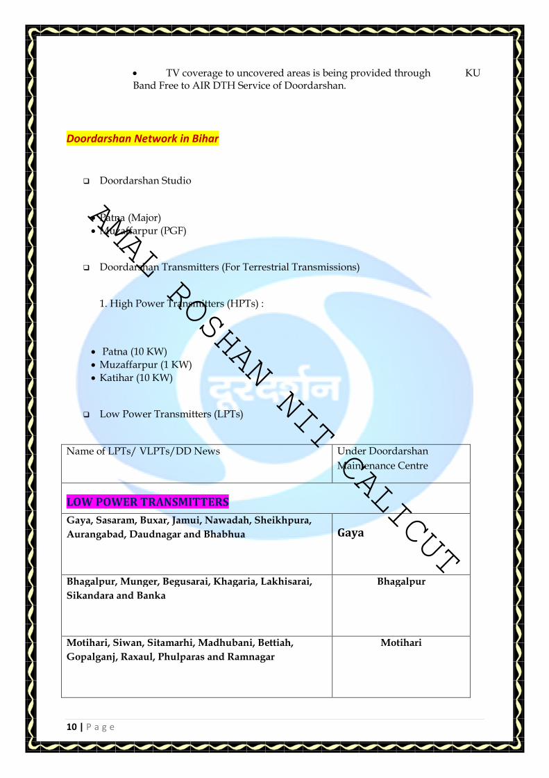
Doordarshan Network in Bihar
� Doordarshan Studio
• Patna (Major)
• Muzaffarpur (PGF)
� Doordarshan Transmitters (For Terrestrial Transmissions)
1. High Power Transmitters (HPTs) :
• Patna (10 KW)
• Muzaffarpur (1 KW)
• Katihar (10 KW)
� Low Power Transmitters (LPTs)
Name of LPTs/ VLPTs/DD News Under Doordarshan
Maintenance Centre
LOW POWER TRANSMITTERS
Gaya, Sasaram, Buxar, Jamui, Nawadah, Sheikhpura,
Aurangabad, Daudnagar and Bhabhua
Gaya
Bhagalpur, Munger, Begusarai, Khagaria, Lakhisarai,
Sikandara and Banka
Bhagalpur
Motihari, Siwan, Sitamarhi, Madhubani, Bettiah,
Gopalganj, Raxaul, Phulparas and Ramnagar
Motihari
AMAL ROSHAN NIT CALICUT
AMAL ROSHAN NIT CALICUT
11 | P a g e
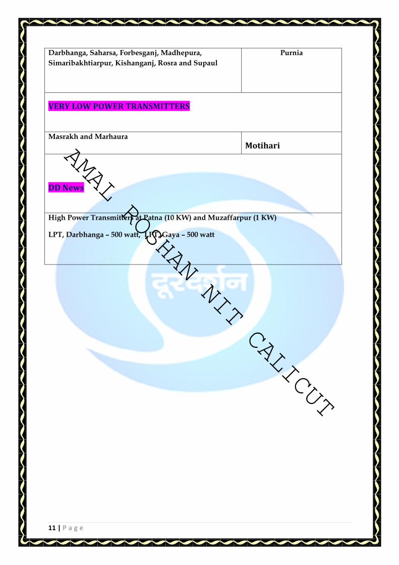
Darbhanga, Saharsa, Forbesganj, Madhepura,
Simaribakhtiarpur, Kishanganj, Rosra and Supaul
Purnia
VERY LOW POWER TRANSMITTERS
Masrakh and Marhaura
Motihari
DD News
High Power Transmitters at Patna (10 KW) and Muzaffarpur (1 KW)
LPT, Darbhanga – 500 watt, LPT, Gaya – 500 watt
AMAL ROSHAN NIT CALICUT

AMAL ROSHAN NIT CALICUT
12 | P a g e
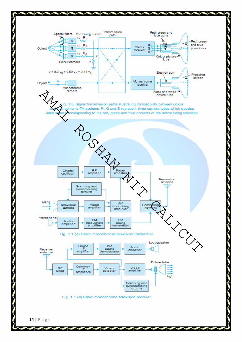
FUNDAMENTALS OF MONOCHROME AND
COLOUR TV SYSTEM
Picture formation A picture can be considered to contain a number of small elementary areas of light or shade
which are called PICTURE ELEMENTS. The elements thus contain the visual image of the
scene. In the case of a TV camera the scene is focused on the photosensitive surface of pick
up device and a optical image is formed. The photoelectric properties of the pick up device
convert the optical image to a electric charge image depending on the light and shade of the
scene (picture elements). Now it is necessary to pick up this information and transmit it. For
this purpose scanning is employed. Electron beam scans the charge image and produces
optical image. The electron beam scans the image line by line and field by field to provide
signal variations in a successive order. The scanning is both in horizontal and vertical
direction simultaneously. The horizontal scanning frequency is 15,625 Hertz. The vertical
scanning frequency is 50 Hz. The frame is divided in two fields. Odd lines are scanned first
and then the even lines. The odd and even lines are interlaced. Since the frame is divided into
2 fields the flicker reduces. The field rate is 50 Hertz. The frame rate is 25 Hertz.
Number of TV Lines per Frame –
If the number of TV lines is high larger bandwidth of video and hence larger R.F. channel
width is required. If we go for larger RF channel width the number of channels in the R.F.
spectrum will be reduced. However, with more no. of TV lines on the screen the clarity of the
picture i.e. resolution improves. With lesser number of TV lines per frame the clarity
(quality) is poor.
AMAL ROSHAN NIT CALICUT

AMAL ROSHAN NIT CALICUT
13 | P a g e
Resolution -The capability of the system to resolve maximum number of picture elements
along scanning lines determines the horizontal resolution. It means how many alternate black
and white elements can be there in a line. The vertical resolution depends on the number of
scanning lines and the resolution factor (also known as Kell factor)
Grey Scale- In black and white (monochrome) TV system all the colours appear as gray on a
10-step gray scale chart. TV white corresponds to a reflectance of 60% and TV black 3 %
giving rise to a Contrast Ratio of 20:1 (Film can handle more than 30:1 and eye's capability is
much more).
Brightness - Brightness reveals the average illumination of the reproduced image on the
TV screen. Brightness control in a TV set adjusts the voltage between grid and cathode of the
picture tube (Bias voltage).
Contrast-
Contrast is the relative difference between black and white parts of the reproduced picture. In
a TV set the contrast control adjusts the level of video signal fed to the picture tube.
Viewing Distance -Optimum viewing distance from TV set is about 4 to 8 times the height of
the TV screen. While viewing TV screen one has to ensure that no direct light falls on the TV
screen.
TELEVISION STANDARDS
• NTSC-National television standards committee(US) (525 Horizontal & 60 vertical lines)
• SECAM-System electronics for colour avec memorie(FRANCE)(625 vertical 50horizantal lines)
• PAL- Phase Alternating lines(GERMANY)(625 horizontal & 50 vertical line) Television standards used in India is PAL.
AMAL ROSHAN NIT CALICUT
AMAL ROSHAN NIT CALICUT
14 | P a g e
AMAL ROSHAN NIT CALICUT

AMAL ROSHAN NIT CALICUT
15 | P a g e
Colour composite Video Signal(CCVS) • What is video signal?
Video is nothing but a sequence of picture. The image we see is maintained in our
eye for a 1/16 sec so if we see image at the rate more than 16 pictures per sec our
eye cannot recognize the difference and we see the continuous motion.
In TV cameras image is converted in electrical signal using photo sensitive material.
Whole image is divided into many micro particle known as Pixels.
These pixels are small enough so that our eyes cannot recognize pixel and we see
continuous image , thus at any instant there are almost an infinite no. of pixel that
needs to be converted in electrical signals simultaneously for transmitting picture
details. However this is not practicable because it is no feasible to provide a separate
path for each pixel in practice this problem is solved by scanning method in which
information is converted in one by one pixel line by line and frame by
frame.
Colour composite video signal is formed with video, sync and blanking signals. The
level is standardized to 1.0 V peak to peak (0.7 volts of video and 0.3 volts of sync
pulse). The Colour Composite Video Signal(CCVS) has been shown in the figure.
Frequency Content of TV Signal The TV signal have varying content. The lowest frequency is zero(when we are
transmitting a white window in the entire active period of 52 micro seconds the
frequency is Zero ). In CCIR system B the highest frequency that can be transmitted is
5 MHz even though the TV signal can contain much higher frequency components.
(In film the reproduction of frequencies is much higher than 5MHz and hence clarity
is superior to TV system.) long shots carry higher frequency components than mid
close ups and close ups. Hence in TV productions long shots are kept to a minimum.
In fact is a medium of close ups and mid close ups.
AMAL ROSHAN NIT CALICUT

AMAL ROSHAN NIT CALICUT
16 | P a g e
DC Component of video signal and DC restoration A TV signal is a continuously varying amplitude signal as the picture elements give rise to
varying level which depends on how much of incident light the picture elements can reflect
and transmit the light signal to the TV camera. Hence the video signal has an average value
i.e. a DC component corresponding to the average brightness of the scene to scene.
RF Transmission of Vision and Sound Signals TV Transmission takes place in VHF Bands I and III and UHF Bands IV and V. Picture is
amplitude modulated and sound is frequency modulated on different carriers separated by
5.5 MHz. Also for video amplitude modulation negative modulation is employed because of
the following main advantages.
Pictures contain more information towards white than black and hence the average power
is lower resulting in energy saving. (Bright picture points correspond to a low carrier
amplitude and sync pulse to maximum carrier amplitude).
Interference such as car ignition interfering signals appear as black which is less
objectionable.
Picture information is in linear portion of modulation characteristic and hence does not
suffer compression. Any compression that may take place is confined to sync pulse only.
The design of AGC circuit for TV Receiver is simpler. AM produces double side bands. The
information is the same in both side bands. It is enough to transmit single side band only.
Carrier also need not be transmitted in full and a pilot carrier can help. However,
suppressing the carrier and one complete side band and transmitting a pilot carrier leads to
costly TV sets. A compromise to save RF channel capacity is to resort to vestigial side band
system in which one side band in full, carrier and a part of other side band are transmitted.
Sound Signal Transmission
In CCIR system B sound carrier is 5.5 MHz above the vision carrier and is
frequency modulated. The maximum frequency deviation is 50 KHz. Also the ratio of
vision and sound carriers is 10:1 (20:1 is also employed in some countries) If we assume
maximum audio signal is 15 KHz the band width is 130 KHz. According to Carson's Rule the
bandwidth is 2 x (Maximum frequency deviation + highest modulating frequency).
However, calculated value(using Bessel's function) of Bandwidth is 150 KHz i.e. 75 KHz on
either side of sound carrier. In CCIR system picture IF is 38.9 MHz and sound.
IF is 33.4 MHz. At the receiver end it is necessary to ensure that signal frequencies in
AMAL ROSHAN NIT CALICUT

AMAL ROSHAN NIT CALICUT
17 | P a g e
the region of the vestigial side band do not appear with double amplitude after
detection. For this purpose the IF curve employs NYQUIIST slope.
The Colour Television It is possible to obtain any desired colour by mixing three primary colours i.e. Red, Blue and
green in a suitable proportion. The retina of human eye consists of very large number of
light- sensitive cells. These are of two types, rods and cones. Rods are sensitive only to the
intensity of the incident light and cones are responsible for normal colour vision. The small
range of frequencies to which the human eye is responsive is known as visible spectrum.
This visible spectrum is from 780 mm (Red) to 380 mm(Violet).
Additive Colour Mixing The figure shows the effect of projecting red, green, blue beams of light so that they overlap
on screen. Y= 0.3 Red + 0.59 Green + 0.11 Blue
Additive colour mixing
AMAL ROSHAN NIT CALICUT

AMAL ROSHAN NIT CALICUT
18 | P a g e
TV STUDIO
A TV studio is an acoustically treated compact anechoic room. It is suitably furnished and
equipped with flood lights for proper light effects. The use of dimmer stats with flood lights
enables suitable illumination level of any particular area of the studio depending on the scene
to be televised. Several cameras are used to telecast the scene from different angles. Similarly
a large number of microphones are provided at different locations to pick up sound associated
with the programme.
In addition to a live studio, video tape recording and telecine machine rooms are located close
to the control room. In most cases, programmes as enacted in the studio are recorded on a
video tape recorder (VTR) through the control room. These are later broadcast with the VTR
output passing through the same control room.
TV STUDIO CONSTITUENTS-
• POWER SUPPLY
• ACOUSTICS
• CAMERA
• AUDIO SYSTEM (MICROPHONE AND AUDIO CONSOLE)
• LIGHTS
• AIR CONDITIONING
• SPEAKERS
• COMMUNICATION SYSTEMS
• POST PRODUCTION AND VIDEO EFFECTS
• MSR
• VTR Patna Doordarshan has 2 dedicated 11kV ac sources. Its power supply is divided into two
parts - (i) Essential (ii) Non Essential power supply. 4 generators (45kv, 45kV, 40kV, 20kV)
are also available for emergency backup. 4 UPS are also available for the same purpose.
AMAL ROSHAN NIT CALICUT

AMAL ROSHAN NIT CALICUT
19 | P a g e
ACTION AREA OF TV STUDIO-
AMAL ROSHAN NIT CALICUT

AMAL ROSHAN NIT CALICUT
20 | P a g e
TV CAMERA
KEY TERMS The camera utilizes two devices that control the amount of light that will reach the sensor.
• One of these devices is the shutter that can be likened to a normally closed opaque
window shade. When activated the window shade will be opened for a predetermined period
of time to admit light to the sensor.
• The other device is the aperture control that is an iris diaphragm located inside the lens
and the diaphragm functions much like the iris in the human eye. This diaphragm is made
either larger or smaller in size to control the amount of light passing through the lens to the
sensor.
• Shutter Speed
• The shutter speed of the camera specifies how fast the shutter will operate that is for how
long a period of time the shutter will be open to admit light through the lens. A faster shutter
speed will be better to stop motion. A slower shutter speed can permit use of a smaller
aperture that will result in a greater depth of field (to be explained in a few minutes). Shutter
speeds are expressed in numbers such as 60, 125, 250 etc. The number 60 means 1/60 of a
second and 125 means 1/125 of a second and so on. A special setting is sometimes included
and labeled B. When B is used the shutter will remain open as long as the shutter release
remains pressed. The B stands for Bulb an expression that goes back to operation of old
cameras. Each time you increase the speed you reduce the light striking the film. As the
shutter speed goes from 60 to 125 you cut the light in half. You do exactly the same if you go
from 250 to 500. Full stop shutter speeds are; 1, ½ , ¼, 1/8, 1/15, 1/30, 1/60, 1/125, 1/250,
1/500, 1/1000, 1/2000, 1/4000, 1/8000.
AMAL ROSHAN NIT CALICUT

AMAL ROSHAN NIT CALICUT
21 | P a g e
Aperture
• The aperture controls the amount of light that passes through the lens to the sensor. On a
cloudy day you need to make the diaphragm opening larger to allow more light to reach the
film and conversely on a bright day at the beach you need to close down the diaphragm to let
less light in. The numbers used to identify the discrete steps are 1.4, 2, 2.8, 4, 5.6 8, 11, 16,
22, etc. and are known as f-stops. I know the numbers are strange looking but they have a
basis in mathematics and as the number increases by one stop the light getting through the
lens is cut in half. Thus if you go from f2 to f2.8 you cut the light in half. You also cut it in
half if you go from f11 to f16. Just to reinforce the idea if you go from f16 to f11 you double
the light reaching the lens. The term “stopping down” refers to closing down the diaphragm
such as going from f11 to f16. Notice as the f-stop numbers get larger the diaphragm gets
smaller.
Lens Selection
• Lens selection has a great affect on your images. Lenses are measured in terms of focal length.
Telephoto lenses have a long focal length and wide- angle lenses have a short focal length. For
35mm a 50mm lens is called a “normal” lens since that lens sees approximately the same field of
view that the human eye and brain see when they look at a scene. Let us look at lenses from the
following perspective. Say that you are standing at one point and attempting to photograph a
subject of a given size with a 50mm lens. If the object that you want to photograph appears too
small in the viewfinder a longer telephoto lens will allow you to fill more of the frame with that
subject without moving closer.
Zoom Lens
A zoom lens has a variable focal length with a range of 10 : 1 or more. In this lens the viewing angle
and field view can be varied without loss of focus. This enables dramatic close-up control. The
smooth and gradual change of focal length by the cameraman while televising a scene appears to
the viewer as it he is approaching or receding from the scene.
The variable focal length is obtained by moving individual lens elements of a compound lens
assembly. A zoom lens can in principle simulate any fixed lens which has a focal length within the
zoom range. It may, however, be noted that the zoom lens is not a fast lens. The speed of a lens is
determined by the amount of light it allows to pass through it. Thus under poor lighting conditions,
faster fixed focal length lenses mounted on the turret are preferred.
AMAL ROSHAN NIT CALICUT

AMAL ROSHAN NIT CALICUT
22 | P a g e
A TYPICAL STUDIO CAMERA
A typical view of cameras used in studios.
In the above figure TV camera and its various
components are shown.
In the right side figure TV camera on a studio
pedestal.
AMAL ROSHAN NIT CALICUT

AMAL ROSHAN NIT CALICUT
23 | P a g e
A TV Camera consists of three sections.
a) A Camera lens & Optics: To form optical image on the face plate of a pick up device
b) A transducer or pick up device: To convert optical image into a electrical signal
c) Electronics: To process output of a transducer to get a CCVS signal
Types of Pickup Devices- a) Photo emissive material: These material emits electrons when the light falls on them. Amount of
emitted electrons depends on the light . Monochrome cameras used in Doordarshan were based on
this material. These cameras were called Image Orticon Cameras. These cameras were bulky and
needed lot of light. These are no longer in use at present.
b) Photo conductive material: The conductivity of these material changes with amount of light falling
on them. Such material with variable conductivity is made part of a electrical circuit. Voltage
developed across this material is thus recovered as electrical signal. Earlier cameras based on this
principle were Videocon Cameras. Such cameras were often used in the monochrome televise chain.
These cameras had serious Lag & other problems relating to dark currents.
Improvement in these cameras lead to the development of Plumb icon and Sat icon cameras.
c) Charge coupled devices: These are semiconductor devices which convert light into a charge image
which is then collected at a high speed to form a signal. Most of the TV Studios are now using CCD
cameras instead of Tube cameras. Tube cameras have become obsolete & are not in use .
AMAL ROSHAN NIT CALICUT

AMAL ROSHAN NIT CALICUT
24 | P a g e
Camera sensors – CCD basics
The CCD is a solid-state device using special integrated circuitry technology, hence it is often referred
to as a chip camera. The complete CCD sensor or chip has at least 450 000 picture elements or
pixels, each pixel being basically an isolated (insulated) photodiode. The action of the light on each
pixel is to cause electrons to be released which are held by the action of a positive voltage.
The Charge held under electrode can be moved to electrode by changing the potential on the second
electrodes. The electrons (negative charges) follow the most positive attraction. A repeat of this
process would move the charges to next electrode, hence charge-coupled device. A system of
transfer clock pulses is used to move the charges in CCDs to achieve scanning.
There are three types of CCD device: frame transfer (FT)
interline transfer(IT)
frame interline transfer (FIT)
Frame transfer (FT)
Frame transfer was the first of the CCDs to be developed and it consists of two identical areas, an
imaging area and a storage area. The imaging area is the image plane for the focused optical image,
the storage area is masked from any light. The electrical charge image is built up during one field
period, and during field blanking this charge is moved rapidly into the storage area. A mechanical
shutter is used during field blanking to avoid contamination of the electrical charges during their
transfer to the storage area. The storage area is „emptied' line by line into a read- out register
where, during line –time, one line of pixel information is „clocked' through the register to produce
the video signal.
Interline transfer (IT)
Interline transfer CCDs were developed to avoid the need for a mechanical shutter The storage cell is
placed adjacent to the pick-up pixel; during field blanking the charge generated by the pixel is shifted
sideways into the storage cell. The read-out process is similar to the frame transfer device, with the
storage elements being „clocked' through the vertical shift register at field rate into the horizontal
shift register, then the charges read out at line rate. Earlier forms of IT devices suffered from severe
vertical smear, which produced a vertical line running through a highlight. This was caused by
excessive highlights penetrating deeply into the semiconductor material, leaking directly into the
vertical shift register. Later IT devices have improved the technology to make this a much less
objectionable effect.
Frame interline transfer (FIT)
Frame interline transfer CCDs are a further development of the interline transfer device to overcome
the problem of vertical smear. As its name suggests, it is a combination of both types . The FIT
sensor has a short-term storage element adjacent to each pixel (as IT) and a duplicated storage area
AMAL ROSHAN NIT CALICUT

AMAL ROSHAN NIT CALICUT
25 | P a g e
(as FT). During field blanking the charges are moved from the pixels into the adjacent short-term
storage element and then moved at 60 times field frequency into the storage area. This rapid
moving of the charge away from the vulnerable imaging area overcomes the vertical smear problem.
Development in CCD technology has seen the introduction of:
• The hole accumulated Diode (HAD) sensor which enabled up to 750 pixels/line, with
increased sensitivity and a reduction in vertical smear;
• The hyper HAD sensor, which included a microlens on each pixel to collect the light more
efficiently (this gave a one stop increase in sensitivity over the HAD sensor);
• The power HAD sensor with improved signal-to- noise ratio which has resulted in at least
half an ƒ-stop gain in sensitivity; in some cases a full ƒ-stop of extra sensitivity has been
realized.
CCD CAMERAS (Charge coupled devices)—
A typical three tube camera chain is described in the block diagram. The built in sync pulse generator
provides all the pulses required for the encoder and colour bar generator of the camera. The signal
system is described below:
The signal system in most of the cameras consists of processing of the signal from red, blue and
green CCD respectively. The processing of red and blue channel is exactly similar. Green channel
which also called a reference channel has slightly different electronic concerning aperture
correction. So if we understand a particular channel, the other channels can be followed easily. So
let us trace a particular channel. The signal picked up from the respective CCD is amplified in a stage
called pre-pre amplifier. It is then passed to a pre amplifier board with a provision to inserts external
test signal. Most of the cameras also provide gain setting of 6 dB, 9dB and 18dB at the pre amplifier.
Shading compensator provides H and V shading adjustments in static mode and dynamic mode by
readjusting the gain. After this correction the signal is passed through a variable gain amplifier which
provides adjustment for auto white balance, black balance and aperture correction. Gama correction
amplifier provides suitable gain to maintain a gamma of 0.45 for each channel. Further signal
AMAL ROSHAN NIT CALICUT
AMAL ROSHAN NIT CALICUT
26 | P a g e
processing includes mixing of blanking level, black clip, white clip and adjustment for flare
correction. The same processing take place for blue and red channels. Green channel as an
additional electronic which provides aperture correction to red and blue channels. Aperture
correction provide corrections to improve the resolution or high frequency lost because of the finite
size of the electron beam . Green channel has fixed gain amplifier instead of variable gain amplifier
in the red and blue channels.
All the three signals namely R, G and B are then fed to the encoder section of the camera via a
colour bar/camera switch. This switch can select R, G and B from the camera or from the R, G, B
Signal from colour bar generator. In the encoder section these R, G, B signals are modulated with SC
to get V and U signals. These signals are then mixed with luminance, sync, burst, & blanking etc. to
provide colour composite video signal (CCVS Signal). Power supply board provides regulated voltages
to various sections.
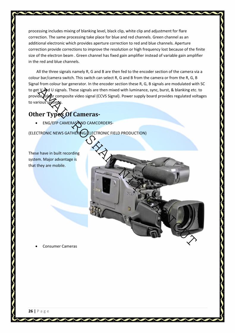
Other Types Of Cameras-
• ENG/EFP CAMERAS AND CAMCORDERS-
(ELECTRONIC NEWS GATHERING/ELECTRONIC FIELD PRODUCTION)
These have in built recording
system. Major advantage is
that they are mobile.
• Consumer Cameras
AMAL ROSHAN NIT CALICUT

AMAL ROSHAN NIT CALICUT
27 | P a g e
• Proconsumer Cameras
AMAL ROSHAN NIT CALICUT
AMAL ROSHAN NIT CALICUT
28 | P a g e
STUDIO LIGHTINGSTUDIO LIGHTINGSTUDIO LIGHTINGSTUDIO LIGHTING
GENERAL PRINCIPLES:
Lighting for television is very exciting and needs creative talent. There is always a
tremendous scope for doing experiments to achieve the required effect. Light is a kind of
electromagnetic radiation with a visible spectrum from red to violet i.e., wavelength from
700 nm to 380 nm respectively. However to effectively use the hardware and software
connected with lighting it is important to know more about this energy.
The lighting control system is the most important tool that the lighting man has to work
with. The lighting control system, commonly called the Dimming System, is the nerve centre
of any lighting package. The Control System allows the studio production lights to be varied
in intensity for the various special effects that are required. It’s dimming system that allows
color blending of the cyclorama curtain background. It is the dimming system that allows
complex light changes to be easily accomplished.
Lighting in studio is of three types-
• Key Light-
It is used to illuminate the main object. It has most intensity.
• Fill Light-
It is used to remove blank shadows and the shadows created by key light.
• Back Light-
It is used to give the object a 3D look. It helps to give a depth in the video.
Other lightings are background lights and lights synchronized with audio.
Light Source: Any light source has a Luminance intensity (I) which is measured in
Candelas. One Candela is equivalent to an intensity released by standard one candle source
of light.
Luminance flux (F): It is a radiant energy weighted by the photonic curve and is
measured in Lumens. One Lumen is the luminous flux emitted by a point source of 1
Candela.
Illumination (E): It is a Luminous Flux incident onto a surface. It is measured in
LUMENS/m2, which is also called as LUX. A point source of 1 candela at a uniform
distance of 1 meter from a surface of 1 square meter gives illumination of 1 LUX.
Luminance (L): It is a measure of the reflected light from a surface. Measured in
Apostilbs . A surface which reflects a total flux of 1 lumen/m2 has a luminance of 1
AMAL ROSHAN NIT CALICUT

AMAL ROSHAN NIT CALICUT
29 | P a g e
Aposilbs .
Elementary theory of light also says that:
Colour temperature:
One may wonder, how the light is associated with color . Consider a black body being
heated; you may observe the change in colour radiated by this body as the temperature
is increased. The colour radiated by this body changes from reddish to blue and then to
white as the temperature is further increased. This is how the concept of relating colour
with temperature became popular. Colour temperature is measured in degree Kelvin
i.e., 0C +273) . The table below gives idea about the kind of radiation from different
kinds of lamps in terms of colour temperature.
a) Standard candle 19300K
b) Fluorescent Lamps range 3000-6500oK
c) HMI lamp 5600+- 400oK
(H=Hg, M=Medium arc, I=Metal Iodide}
d) CSI (Compact Source Iodide) 4000+- 400oK
e) CID (Compact Iodide Daylight) 5500+- 400o
Colour TV Display,white 6500oK
f) Monochrome TV 9300oK
g) Blue sky 12000 – 18000oK
h) Tungsten Halogen 3200oK
i) Average summer sunlight (10am –3pm) 5500oK
It can be noted that as the temperature is increased, the following things
happen:
1) Increase in maximum energy released
2) Shift in peak radiation to shorter wavelengths (Blue)
3) Colour of radiation is a function of temperature
Hence by measuring the energy content of the source over narrow bands at the red and
blue ends of the spectrum ,the approximate colour temperature can be determined. All the
color temperature meter are based on this principle.
AMAL ROSHAN NIT CALICUT

AMAL ROSHAN NIT CALICUT
30 | P a g e
COLOUR FILTERS AND THEIR USE:
Colour filters are used to modify the colour temperature of lights and to match colour
temperature for cameras while shooting with different colour temperature. These filters
change the colour temperature at the cost of reduction in light transmission. Colour
temperature filters are also introduced in the optical path of cameras to facilitate camera
electronics to do the white balance without loading the amplifier chain. Cameras electronics
is generally optimized for a colour temperature of 3200K, hence it uses reddish filter while
shooting at higher colour temperatures.
Generally it is normal to correct daylight to produce tungsten quality light, because it is
usually easier to do and saves lot of power, otherwise blue filters are going to reduce lot of
light thus requiring the use of higher wattage lamps.. However, when the amount of
tungsten to be corrected is small it may be more practical to convert it to daylight, but with
a considerably reduced light output form the luminaries. There are two basic types of filter:-
i) One which is orange in colour and converts Daylight to Tungsten Light.
ii) One which is blue in colour and converts Tungsten to Daylight.
Day Light: -
The sun does not changes its colour temperature during the day it is only its appearance
from a fixed point on earth. It is because the sunlight gets scattered because of the medium,
shorter wavelengths like blue gets more effected. Certain situations like, sunrise and sunset
causes the light to be more yellow than midday, because the light has to travel the long
distance so a careful note should be made of the Transmission factor of each of the filters.
Often a compromise has to be reached in terms of correction and light loss.
NEUTRAL DENSITY FILTERS :-
In addition to colour temperature correction sometimes it may be necessary to reduce the
intensity of daylight at an interior location. Neutral density filters available to attenuate the
light are of:
0.3 Density which has a transmission of 50%= 6dB=1 f stop
0.6 Density which has a transmission of 25%= 9dB=2 f stop
0.9 Density which has a transmission of 13%= 12dB=3f stop
COMBINATION OF CTC FILTERS AND NEUTRAL DENSITY
FILTERS:
Single filters exist which are a combination of full colour temperature orange and neutral
density as follows:-
Full Orange + 0.3 N.D. with a transmission of 50%
Full Orange + 0.6 N.D. with a transmission of 38%
The HMI light source has a colour temperature of about 60000K and can be used with
exterior daylight without the need for a colour temperature correction filter.
AMAL ROSHAN NIT CALICUT

AMAL ROSHAN NIT CALICUT
31 | P a g e
DIFFERENT LIGHTING TECHNIQUES:
- Eye light, Low intensity light on camera itself to get extra sparkle to an actor's eye
-Rim light, to highlight actor's outline, it is an extra back on entire body at camera level
- Kickkar light, Extra light on shadow side of the face at an angle behind and to the side of
the actor
- Limbo Lighting, Only subject is visible, no back ground light
- Sillhoutt lighting, No light on subject, BG is highly lit
LIGHTING CONSOLE
In a television production, each scene will require its own lighting plan to give the desired
effect. In order to assist in setting up a particular lighting plon, a console should provide :-
a) One man operation and a centralised control desk with ability to switch any circuit.
b) Facilities to obtain good balance with flexibility to have dimming on any circuit.
c) With all controls for power at low voltage and current.
Modern lighting consoles also provide file & memory to enable the console operator to
store and recall the appropriate luminaries used for a particular lighting plot. These console
also provide Mimic panels to show which channels are in use and which memories or files
have been recalled.
DIMMERS
Three basic methods for dimming are :-
1. Resistance
This is the simplest and cheapest form of dimmer. It consists of a wire wound resistor with a
wiper .It is used in series with the load.
2. Saturable Reactor (System SR)
The basic principle of the saturable reactor is to connect an iron cored choke in series with
the lamp. Dimmers are controlled with the help of main switch. A typical dimmer bank is
shown.
LIGHTING THE SET FOR DRAMA:--
Openings such as windows within a set should be
highlighted without overstating them. Where the
walls having such feature should be lit to reveal
these features but care must be taken to ensure
that there is only one shadow. The top of the set
should be darkened off by using the barndoors,
this puts a "ceiling" on the set by giving the
feeling of a roof. If more than the top of the set
is darkened, that gives enclosed feeling.
AMAL ROSHAN NIT CALICUT

AMAL ROSHAN NIT CALICUT
32 | P a g e
Indoor day time:
1. If there is a choice in the direction of the 'sun'(Key) take the shortest route inside the set
to a wall, and if possible throw the shadow of window bars onto a door - it usually is in shot.
2. A patch of light on the floor inside the set, backlight from outside using a soft source at
steep elevation adds realism.
3. When a set does not have a window, a window pattern can be projected onto a wall to
produce a suitable window effect.
4. Roof and Ceiling Pieces - if they make lighting impossible, check if they can be removed at
the planning state. Light any ceiling pieces from outside, use a soft source at ground level. If
the ceiling has plaster moulding or ornamentation, a hard source may be used.
Indoor night time:
- The outside of the window should be dark, except for a possible dim skyline if the room is
well above adjacent streets, or lit by an outside practical lamp i.e. street lighting.
- The wall with the window in it should be lit at night to be brighter than for the day
condition. Subjectively the walls appear brighter at night than at daytime.
- Often a completely different 'feel' to the set can be obtained by reversing he direction of
lighting in the set compared to that used for day.
- General for night effects it is not a good plan to just simply dim the set lighting when
changing from day to night. This is because the excessive change in colour temperature of
the light source and the apparent increase in saturation of surfaces at low luminance.
Outdoor daylight and Moonlight:
The direction of the light is dictated by the position of the 'sun' or 'moon'. As a general
principle one should remember that sunlight (hard source) is accompanied by the reflected
"skylight" (soft source) whereas moonlight is a single hard source. One of the biggest
problems when lighting exteriors is the maintenance of “single shadow" philosophy - double
shadows on a long shot will quickly destroy the apparent realism created in the set. Very
large area filler light is ideal for exterior daylight scenes.
This can be achieved by using a suspended white screen 12' x 8' where the filler would be
positioned then lighting it with hard light.
The exact lighting treatment will depend on the situation but as a general rule, moonlight
effects are normally achieved by back lighting to give a more softer, romantic mood than
would be achieved than a frontal key.
In colour, to obtain a night effect, blue cinemoid is used over the luminaries. This gives a
stylised effect. An alternative is to use much more localised lighting than for daylight and
light only the artists and odd parts of the set.
AMAL ROSHAN NIT CALICUT
AMAL ROSHAN NIT CALICUT
33 | P a g e
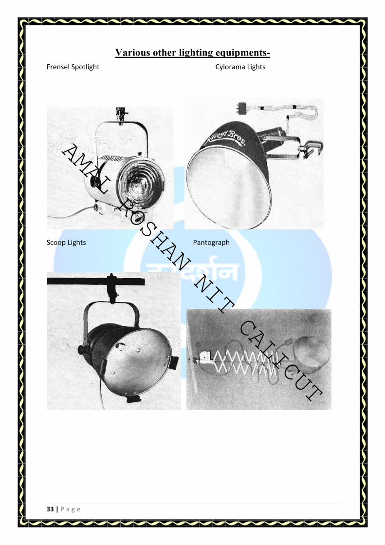
Various other lighting equipments-
Frensel Spotlight Cylorama Lights
Scoop Lights Pantograph
AMAL ROSHAN NIT CALICUT

AMAL ROSHAN NIT CALICUT
34 | P a g e
Dynabeam Lights Wide Anlge Lights
Lightbeam with Patterns
Space Cycle lights
AMAL ROSHAN NIT CALICUT

AMAL ROSHAN NIT CALICUT
35 | P a g e
MICROPHONES
Introduction Pressure variations, whether in air, water or other mediums, which the human ear can detect,
are considered sounds. Acoustics is the science or the study of sound. Sound can be generally
pleasing to the ear, as in music, or undesirable, referred to as noise. The typical audible range
of a healthy human ear is 20 to 20,000 Hz. A Sound Pressure Level
(SPL) beyond the detectable frequencies of the human ear can also be very important to
design engineers. Noise, Vibration and Harshness (NVH) is concerned with the study of
vibration and audible sounds. Vibrations represent a rapid linear motion of a particle or of an
elastic solid about an equilibrium position, or fluctuation of pressure level.
Harshness refers to the treatments of transient frequencies or shock. Usually
treatments are employed to eliminate noise, but in some cases products are designed to
magnify the sound and vibration at particular frequencies. The sound
produced or received by a typical object, which may be above and below the frequencies that
are detectable by the human ear, or amplitudes concerning its resonant
frequencies, are important to designers, in order to characterize the items performance and
longevity.
Technology Fundamentals and Microphone Types
When an object vibrates in the presence of air, the air molecules at the surface will begin to
vibrate, which in turn vibrates the adjacent molecules next to them. This
vibration will travel through the air as oscillating pressure at frequencies and amplitudes
determined by the original sound source. The human eardrum transfers these
pressure oscillations, or sound, into electrical signals that are interpreted by our brains
as music, speech, noise, etc. Microphones are designed, like the human ear, to transform
pressure oscillations into electrical signals, which can be recorded and analyzed to tell us
information about the original source of vibration or the nature of the path the sound took
from the source to the microphone. This is exhibited in testing of noise reducing materials.
Pressure from sound must be analyzed in the design stages to not only protect the
AMAL ROSHAN NIT CALICUT

AMAL ROSHAN NIT CALICUT
36 | P a g e
materials around it, but also to protect the most precious and delicate
mechanism designed to perceive it, the human ear. Like the human ear,
microphones are designed to measure a very large range of amplitudes, typically measured
in decibels (dB) and frequencies in hertz (Hz.)
In order to convert acoustical energy into electrical energy, microphones are used. There are a
few different designs for microphones. The more common designs are Carbon
Microphones, Externally Polarized Condenser Microphones, Prepolarized Electret
Condenser Microphones, Magnetic Microphones, and Piezoelectric Microphones.
Types of microphone Connectors-
• BALANCED
In general, microphones provide an analogue au- dio
signal. Professional microphones feature an
XLR-output with three pins that transfer a balanced
signal. One pin is ground, and the other two carry the audio
signal. Pin 2 is the so called hot signal and pin 3 the
cold. This method reduces the susceptibility of external
noise while allowing the usage of longer cables.
• UNBALANCED
Entry level microphones often feature an attached cable with
an unbalanced 6.3 mm or 3.5 mm con- nector. An unbalanced
output carries the signal on a single conductor and is more
susceptible to external noise. For that reason only balanced
connections are used in professional miking applications.
• USB
More and more professional USB microphones are available. A
USB microphone is essentially a mic with a built-in USB audio
interface that converts the analogue signal into a digital signal. It
can be directly plugged into a computer without requiring an exter-
nal audio interface.
USB microphones, such as the Shure PG27USB and the
PG42USB with plug and play functionality are an easy start into
home recording and podcasting.
AMAL ROSHAN NIT CALICUT

AMAL ROSHAN NIT CALICUT
37 | P a g e
Types of Microphones
• Dynamic
Dynamic microphones employ a diaphragm, a voice coil and a magnet. The voice
coil is sur-rounded by a magnetic field and is attached to the rear of the diaphragm. The
motion of the voice coil in this magnetic field field generates the electrical signals corresponding to
the picked up sound. Dynamic microphones have a relatively simple construction and are
therefore economical and rugged. They can handle extremely high sound pressure levels
and are largely unaffected by extreme temperatures or humidity.
• Condenser
Condenser microphones are based on an electrically-
charged diaphragm/ backplate assembly which forms a
soundsensitive capacitor. When the diaphragm is set in motion
through sound, the space between the diaphragm and the
backplate is changing, and therefore the capacity of the
capacitor. This variation in spacing produces the electrical signal.
Condensers are more sensitive and can provide a smoother, more
natural sound, particularly at higher frequencies. All condenser microphones need to be powered:
either by batteries in the microphone,by phantom power provided by a mixer, a sound card or an
external analogue to digital converter
There are two main types of condenser microphones:
Small diaphragm – generally used for live performance and recording. They are called
small diaphragm because the transducer’s diaphragm is less than one inch in diameter.
Small diaphragm microphones provide a more natural sound reproduction and are
preferably used for miking instruments.
Large diaphragm – traditionally favored by recording studio engineers and broadcast
announcers, condenser microphones with a large diaphragm (one inch in diameter or
larger) usually have higher output, less self-noise (the “hiss“ the microphone might
make), and better low-frequency response, which can result in a “higher fidelity“
sound for both vocals and instruments.
AMAL ROSHAN NIT CALICUT
AMAL ROSHAN NIT CALICUT
38 | P a g e
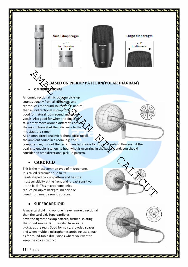
BASED ON PICKUP PATTERN(POLAR DIAGRAM)
• OMNIDIRECTIONAL
An omnidirectional microphone picks up
sounds equally from all directions and
reproduces the sound source more natural
than a unidirectional microphone. It is
good for natural room sound and group
vocals. Also good for when the singer or
talker may move around different sides of
the microphone (but their distance to the
mic stays the same).
As an omnidirectional microphone picks up all
the ambient sound in a room, e.g. the
computer fan, it is not the recommended choice for home recording. However, if the
goal is to enable listeners to hear what is occurring in the background, you should
consider an omnidirectional pick-up pattern.
• CARDIOID
This is the most common type of microphone.
It is called “cardioid“ due to its
heart-shaped pick up pattern and has the
most sensitivity at the front and is least sensitive
at the back. This microphone helps
reduce pickup of background noise or
bleed from nearby sound sources.
• SUPERCARDIOID
A supercardioid microphone is even more directional
than the cardioid. Supercardioids
have the tightest pickup pattern, further isolating
the sound source. But they also have some
pickup at the rear. Good for noisy, crowded spaces
and when multiple microphones arebeing used, such
as for round-table discussions where you want to
keep the voices distinct
AMAL ROSHAN NIT CALICUT

AMAL ROSHAN NIT CALICUT
39 | P a g e
ON THE BASIS OF FREQUENCY RESPONSE-
• FLAT FREQUENCY RESPONSE
All audible frequencies (20 Hz – 20 kHz) have
the same output level. This is most
suitable for applications where the sound
source has to be reproduced without
changing or “coloring” the original sound.
• TAILORED FREQUENCY RESPONSE
A tailored response has varying output levels
across the frequency range and is usually
designed to enhance a sound source in a
particular application. For instance, a bass
drum microphone does not need to reproduce
high frequencies above 6 kHz or a vocal
microphone may have a peak in the 2 – 4 kHz
range to increase intelligibility
MIicrophone in a recording
studio
AMAL ROSHAN NIT CALICUT

AMAL ROSHAN NIT CALICUT
40 | P a g e
CABLES AND CONNECTORS
• The earliest use of cables was in Telegraphy lines. The cables were termed as SWER (Single
Wire Earth Return) circuits. These are single phase lines (un-insulated), that were used in
Single Wire Transmission. The use of this form of communication soon started having
interference (noise) from the Trams (Electric Trains) and other electricity-using devices.
• After this, companies converted to Balanced circuits lines. These are implemented using two
wires which have circuits installed at every distance, or at the receiving or transmitting end,
that cancel out the interference.
– Secondly, since the they are two wires, on transmitting and the other receiving, the
interference in the two lines is canceled out automatically.
– Balanced lines increase length by decreasing the signal attenuation.
• Since most of the telephone lines were installed next to power lines, this caused the
interference that is induced from the power lines, and with the advancement of power, the
interference kept on increasing.
• This brought in a new era of the wire transposition, Figure 4 in a bid to reduce on the
interference induced into the cables. In wire transposition, the transmit and receive cables
change position every 6 to 7 poles (around 4 twists every Kilometer). The change in position
helps to increase interference cancelation.
The wire transposition was not enough in the reduction of noise in the communication lines. This led
to the introduction of twisted pair cables.
Types of Cables-
1. E1
2. Ethernet
3. Coaxial
4. Fiber
5. Waveguide
6. Wireless Medium
E1/T1-
Depending on the Size of the Cable, it can carry from 8 to 32 E1s/T1s, each E1 being made up of
4 twisted cables. Each pair of cables is twisted onto each other to achieve noise cancellation.
Please note that E1s can also be achieved using the an RJ 45 Connector.
Coaxial-Coaxial cables provide the simplest and most versatile method for transmission of RF
and microwave energy. The common types consist of a cylindrical metallic inner conductor
surrounded by a dielectric material and then enclosed by a cylindrical metallic outer conductor.
AMAL ROSHAN NIT CALICUT

AMAL ROSHAN NIT CALICUT
41 | P a g e
The dielectric material is used to maintain the inner conductor concentrically within the outer
conductor. The dielectric material is typically polyethylene (PE), Polyproplene (PP) or
tetraflouroethylene (TFE). Most coaxial cables are then coated with a protective jacket made of
polyethylene or poly-vinyl chloride (PVC).
Fiber-
An optical fiber or optical fiber is a thin, flexible, transparent fiber that acts as a waveguide, or
"light pipe", to transmit light between the two ends of the fiber. Optical fibers are widely used in
fiber-optic communications, which permits transmission over longer distances and at higher
bandwidths (data rates) than other forms of communication. Fibers are used instead of metal
wires because signals travel along them with less loss and are also immune to electromagnetic
interference. Fibers are also used for illumination, and are wrapped in bundles so they can be
used to carry images, thus allowing viewing in tight spaces. Specially designed fibers are used for
a variety of other applications, including sensors and fiber lasers.
Optical fiber typically consists of a transparent core surrounded by a transparent cladding
material with a lower index of refraction. Light is kept in the core by total internal reflection. This
causes the fiber to act as a waveguide.
Two types of Fiber media :
Multimode
Singlemode
Single-mode fiber
Carries light pulses along single path
Uses Laser Light Source
Has a very small core and carry only one beam of light. It can support Gbps data
rates over > 100 Km without using repeaters.
Multimode fiber
Many pulses of light generated by LED travel at different angles
Can support less bandwidth than Single mode Fiber
AMAL ROSHAN NIT CALICUT

AMAL ROSHAN NIT CALICUT
42 | P a g e
Waveguides-
In electromagnetics and communications engineering, the term waveguide may refer to any
linear structure that conveys electromagnetic waves between its endpoints. However, the
original and most common meaning is a hollow metal pipe used to carry radio waves. This type
of waveguide is used as a transmission line mostly at microwave frequencies, for such purposes
as connecting microwave transmitters and receivers to their antennas, in equipment such as
microwave ovens, radar sets, satellite communications, and microwave radio links.
A dielectric waveguide employs a solid dielectric rod rather than a hollow pipe. An optical fiber is
a dielectric guide designed to work at optical frequencies. Transmission lines such as microstrip,
coplanar waveguide, stripline or coaxial may also be considered to be waveguides.
The electromagnetic waves in (metal-pipe) waveguide may be imagined as travelling down the
guide in a zig-zag path, being repeatedly reflected between opposite walls of the guide. For the
particular case of rectangular waveguide, it is possible to base an exact analysis on this view.
Propagation in dielectric waveguide may be viewed in the same way, with the waves confined to
the dielectric by total internal reflection at its surface. Some structures, such as Non-radiative
dielectric waveguide and the Goubau line, use both metal walls and dielectric surfaces to confine
the wave.
Types of waveguides:
- Rectangular waveguide: This is the most commonly used form of waveguide and has a
rectangular cross section.
- Circular waveguide: Circular waveguide is less common than rectangular waveguide. They have
many similarities in their basic approach, although signals often use a different mode of
propagation.
- Circuit board stripline: This form of waveguide is used on printed circuit boards as a
transmission line for microwave signals. It typically consists of a line of a given thickness above
an earth plane. Its thickness defines the impedance.
Uses:
- Optical fibers applications
- In microwave, a waveguide guides microwaves from a magnetron were waves are formed.
- In radar applications
Stripline – Waveguides for printed circuit boards
Waveguides
AMAL ROSHAN NIT CALICUT

AMAL ROSHAN NIT CALICUT
43 | P a g e
Important parameters of cables-
1. Characteristic Impedance
2. VSWR (Voltage Standing Wave Ratio)
3. Capacitance
4. Power Rating
5. Maximum Operating Voltage
6. Attenuation
7. Electrical length stability
8. Pulse Response
9. Shielding
10. Cut Off frequency
11. Flexibility
12. Cable design and Construction
13. Operating temperature range
14. Cable noise
Various Types of Connectors Used Are-
� BNC connectors (Bayanet Neill Concelnam/ Bayanet Navy Connector)
� SMA connectors (Subminiature A)
� SMC connectors (Subminiature C)
� TNC connectors (Threshold Navy Connectors)
� RCA connector (Radio Connector of America)
� Elbow connectors
AMAL ROSHAN NIT CALICUT
AMAL ROSHAN NIT CALICUT
44 | P a g e
PRINCIPLES OF VIDEO TAPE
RECORDING
Introduction
Video tape recorder is a most complex piece of studio equipment with analog and digital processing
servo system, microprocessors, memories, logic circuits and mechanical devices etc. Also these
recorders have been the main limitation so for as the quality output from studio is concerned. Right
from fifties, continuous efforts are being made to improve its performance so as to reproduce
cameras faithfully by improving S/N ratio and resolution. Designer for video tape recorders had to
consider the following differences in the video and audio signals:
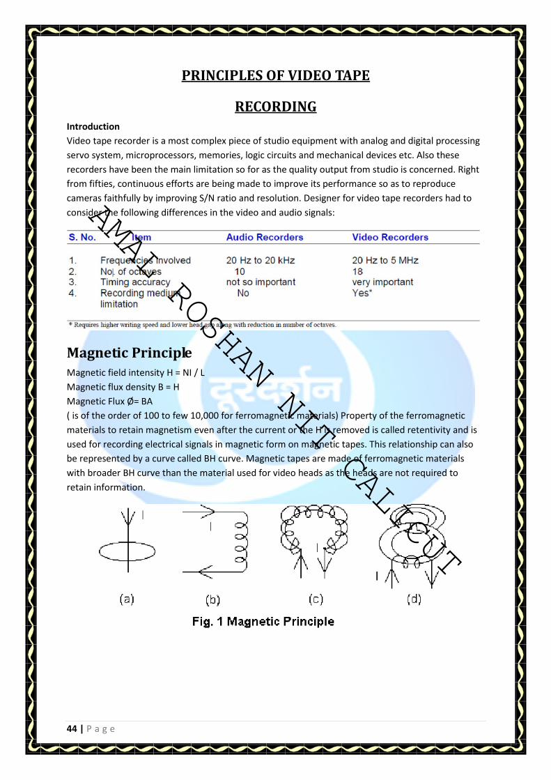
Magnetic Principle
Magnetic field intensity H = NI / L
Magnetic flux density B = H
Magnetic Flux Ø= BA
( is of the order of 100 to few 10,000 for ferromagnetic materials) Property of the ferromagnetic
materials to retain magnetism even after the current or the H is removed is called retentivity and is
used for recording electrical signals in magnetic form on magnetic tapes. This relationship can also
be represented by a curve called BH curve. Magnetic tapes are made of ferromagnetic materials
with broader BH curve than the material used for video heads as the heads are not required to
retain information.
AMAL ROSHAN NIT CALICUT

AMAL ROSHAN NIT CALICUT
45 | P a g e
WRITING SPEED AND FREQUENCY RESPONSE
Recording Process
With reference to given figure when a tape is passed over the magnetic flux bubble,
the electric signal in the coil will cause the electric lines of force from the head gap to
pass through the magnetic material of the tape producing small magnets depending upon the
strength of the current. Polarity of the magnetic field which causes these bar magnets depends on
the change of current. Decreasing current will cause NS magnet and vice versa. Power of these
magnets is as per BH curve. Thus the magnetic flux strengthens the unarranged magnetic particles as
per the signal and they stay in that condition after the tape has already passed the
magnetic head (fig. 2). Length of the magnet thus formed is directly proportional to
writing speed of the head v, and inversely proportional to the frequency of the signal to be
recorded, i.e.
Recorded wavelength for one cycle of signal = speed x time
Or Wave length of the magnetic signal tape = v / f
Recording Process
the problem to be solved in the development of VTRs was how to provide higher speed to record
very high frequencies.
The other limitation of recording medium is the range, during when the extracted signal is more
than noise. This range is only 10 octaves. Thus the system can no longer be used
for recording/reproduction after this dynamic range of 60 db, because of 6 dB/octave
playback response characteristics. Beyond this range the low frequencies becomes inaudible and the
higher frequencies become distorted.
During the initial stages it was tried to record video signal with stationary video heads
and longitudinal tracks using tape speed of the order of 9 m/s which was very difficult
to control besides very high tape consumption i.e, miles of tape for 3 to 4 minutes of recording and
this was coupled with breaking of video signal frequencies into 10 parts recorded by 10
different video heads and then switched during playback to retrieve the signal. The
quality of the reproduced signal was also compromised up to the resolution of 1.7 MHz
or so. Around 1956 the ‘AMPEX' company of USA then came out with Quadruplex machines
having two revolutionary ideas which laid the foundation of present day VTRs/VCRs.
AMAL ROSHAN NIT CALICUT

AMAL ROSHAN NIT CALICUT
46 | P a g e
These ideas were:
1. Rotating Video Heads and
2. Frequency Modulation before recording
Increase in writing speed by rotating head
When a video head mounted on a rotating head wheel writes on a tape moving across it, will lay a
track of length which will depend not only on the speed of the tape but also on the rotating speed of
the head. Single head with diameter d number of rotation per sec as r and full omega wrap or two
heads in ½ omega wrap i.e. little over 180 degree, which most of the present day VCR are using, will
have a writing speed of dr minus or plus the linear tape speed (which is negligible as compared to
the rotating speed). This avoids the requirements of miles of tape for few minutes of recording in a
stationary head type of recorders tried earlier.
Monitoring During Recording
Most of the video tape recorders provide Electronics to Electronics monitoring (EE Mode) at the time
of recording. The video signal is monitored after routing it through all the signal system electronics
of the recorders excluding the video heads and preamplifiers etc. Some of the recorders also provide
simultaneous playback for the off tape monitoring by using additional heads during recording called
confidence heads.
Thus the VTRs could achieve wider frequency range with:
a) Faster writing speed
b) Smaller gap, and
c) Octave band compression with frequency modulation.
Also achieving accurate speed for motors with servo system reduces the timing errors.
Playback process
During play back when the recorded tape is passed over the head gap at the same speed at which it
was recorded, flux lines emerging from the tape on crossing the head gap induce voltage in the coil
proportional to the rate of change of flux, i.e. d /dt and this in turn depends on the frequency of the
recorded signal. Doubling of frequency causes voltage to increase by 6 dB. This
accounts for the well known 6 dB/octave playback characteristics of the recording medium. This
holds good only up to a certain limit thereafter at very high frequencies, lot of losses take place
during playback and recording process causing noise to be more than the signal itself. It may be
noted that when the gap becomes equal to the wavelength of the recorded signal, two adjoining bar
magnets may produce opposite current during playback and the output becomes zero.
Similar thing happens when the gap equals 2, 3 …n. times the wavelength. First extinction
frequency occurs when gap becomes equal to wavelength. For getting maximum output,
head gap has to be one half of wavelength.
Frequency at which zero output occurs is called extinction frequency . Thus the maximum
usable frequency becomes half of the extinction frequency. These parameters are related by:
AMAL ROSHAN NIT CALICUT

AMAL ROSHAN NIT CALICUT
47 | P a g e
Playback Process
So in order to record the higher frequencies we must increase the writing speed for a minimum
value of wave length recorded on tape i.e. tape. This minimum value of tape is again restricted
by the minimum practically possible head gap.
Now the ratio of video and audio frequencies is approximately 300, so we must increase the
writing speed or reduce the gap by the same factor of 300 to get the desired results. Perhaps a
speed of 60 mph will be required to cope with the higher video frequencies.
VIDEO TAPE FORMATS-
INTRODUCTION
Format of Video tape recorder defines the arrangement of magnetic information on the tape. It
specifies:
1. The width of tape,
2. Number of tracks for Video, Audio, Control, time code and cue,
3. Width of tracks,
4.Their electrical characteristics and orientation.
All machines conforming to one format have similar parameters to enable compatibility or
interchange i.e. the tape recorded on one machine is faithfully reproduced on the other. There
are a number of formats in Video tape recording and the number further gets multiplied due to
different TV. Standards prevailing in various countries e.g. PAL, SECAM, NTSC and PAL-M.
CLASSIFICATION OF FORMAT:
A) Analog Formats:
VTRs using composite Video for professional Broadcast use were , Quadruplex 2” , 1" format and
C ( All reel/Spool Type) which were then replaced by U- matic cassette recorders followed by
best quality analog format with separate luminance & chrominance recording called component
Analog formats. These were Betacam SP from SONY & M-II from Panasonic.
a) Quadruplex Format (Segmented)
This was the first professional broadcast video tape recorder introduced by AMPEX in 1956 and
has since been replaced by 1" recorders of type B and type C formats. This format uses spool of
2" wide tape, 4 heads on transversely mounted drum, with a very high writing speed of about
41m/s. These machines had higher operational cost and required constant
AMAL ROSHAN NIT CALICUT

AMAL ROSHAN NIT CALICUT
48 | P a g e
engineering efforts to keep them running. These machines have since been phased out except
for transfer/archival purpose.
b) Type B Format (Segmented helical)
This format was developed by BOSCH/BTS using helical scan with 1" tape as BCN series of Video
Tape recorders. It uses a scanner with head wheel carrying two video heads around which tape
is wrapped in about 190o. Each television field is recorded on six tracks with each head
scanning a 52 line segment. The scanner diameter is 50mm and rotates at 150
rev/sec. The tape moves at 24cms/sec. The 80 mm long tracks are recorded at an angle of
14.3o. There are four longitudinal tracks out of which two are full quality audio tracks, third for
the time code and the fourth for the control track. Video writing speed is 24m/s. The
flying erase head mounted on the same head- wheel and the associated electronics
allows for roll free electronic editing. The addition of digital frame store unit provides freeze
frame and slow motion. The portable version in the same format has also been marketed by the
manufacturers for studio use.
c) Type C Format (field per scan helical)
This is the combined format of AMPEX and SONY using 1" tape with a full omega wrap around a
helical scanner running at 50 rps. Main head mounted on a 135 mm dia drum records one field
i.e.
B). DIGITAL FORMATS
Modern television post production demands multi-layer special effects with several
manipulations having first generation quality. This requires multi-generation playback & a
transparent recordings from Video cassette players./recorders. which can be met only by the
digital formats without loss in picture quality.
Digital Composite/Component Formats
A) D1 format was the first DVTR not to compromise on the technical quality in
any way. It is based on 4:2:2 sampling structure of CCIR-601, completely
transparent in quality but very expensive and bulky. Still it is considered as reference
machine for digital formats and known as father of all digital formats.
It uses 3/4" tape & has a writing speed of about 30m/s.Its drum is running at 150
rps with segmented tracks. Digital coding is in 8-bit words with a raw picture data rate of 216
Mbps.
b) D2 format was the first economical DVTR based on CCIR - 601, 4 fsc sampling on composite
video. It offered easy interface to a composite world at a reasonable cost. It was soon
overshadowed by the then forthcoming D 3 format.
c) D3: D3 was developed by NHK and Panasonic using composite system, 1/2" metal particle
VHS sized cassette thus saving cost. It records 8 bit digital video at a sampling rate of 4 fsc
(17.73MHz) in 8 tracks per field. Data rate is similar to D2.
d) D4: 4 is perhaps an unlucky number in Japan as there is no D4.
e) D5: Panasonic's new component system D5 is a successor to D3. It is digital component
using same cassettes as D3 but running at double speed. In addition to all the
usual facilities, D5 can playback existing D3 tapes. It gives just 2 hours from a
long size cassette. Coding is 10-bit with luminance sampling at 13.5 MHz. D5 can handle
4:3 or 16:9 aspect ratio with full restoration. For 16:9, sampling rate is 18 MHz with 8-bit coding
Based on CCIR 601. It is without any data compression.
AMAL ROSHAN NIT CALICUT

AMAL ROSHAN NIT CALICUT
49 | P a g e
Digital Betacam:
It is based on CCIR 601, and allows 16:9 upgrades. To reduce data rate it uses Bit Rate reduction
(BRR).Bit rate reduction is in the ratio of 2:1. This has been made possible because of the
conversion of data from time domain to frequency domain and removing the redundancy from
the digital video data. Equivalent system without BRR would have required more tape speed,
extra thin tape, and extra narrow tracks and would have also needed double the number of
heads on drum or double the drum speed. It is compatible with Betacam SP and is having 4 PCM
Digital Audio Track. Scanner for this machine is larger then that of Betacam SP but the helix is
such that when rotated at frame rate ,track angle of analog Betacam is traced .This gives a time
compressed replay is which is then expanded in TBC. For digital Betacam, to handle large data
the scanner speed is increased to 3 times. One field is recorded in one and half revolution in 6
tracks of 26 Micrometers each.
BETACAM VIDEO CASSETTE RECORDERS-
INTRODUCTION:
Betacam series of VCRs are based on analog component system. These VCRs had become
popular because of their low initial and running costs in comparison to B and C Format
machines. The quality of reproduction of Betacam SP was near to these analog formats. Betacam
format was introduced in 1982 followed by Betacam SP in 1987. Popular Betacam SP VCRs
which are being replaced with digital VCRs in doordarshan are:- BVW 75P - SP Recorder cum
player, with DT head (Slow motion heads for dynamic tracking) & PVW 2800P PRO SERIES
besides camcorder and portable version of this format .
Head drum :
Head drum for BVW 75P carries as many as 10 video heads, two heads for Luminance Ya, Yb,
two heads for chrominance Ca, Cb, two heads for Dynamic tracking Luminance DTYa, DTYb, two
heads for Dynamic tracking chrominance DT Ca, DT Cb, and finally two heads for Eraser REa &
REb (Rotary erase). In some of the models where slow motion is not available DT heads and
associated electronics is not required. This makes those models cheaper to BVW 75P.
AMAL ROSHAN NIT CALICUT

AMAL ROSHAN NIT CALICUT
50 | P a g e
VIDEO SYSTEM
Video system is based on component analog system. Composite video is decoded into its
component, Luminance Y and colours as R-Y & B-Y. You may note that these colour signal are
base band signal and have nothing to do with 4.43MHz subcarrier frequency. Y is recorded
directly after FM on one of the video tracks by Ya & Yb head. Chrominance signals are first
compressed as CTDM signal (Compressed time division multiplexing) and then frequency
modulated. This FM chroma is then mixed with AFM audio channel 3 & 4 before it is recorded
along with chrominance information.
TAPE TRANSPORT FOR PVW SERIES OF BETACAM SP
AMAL ROSHAN NIT CALICUT

AMAL ROSHAN NIT CALICUT
51 | P a g e
DIGITAL VIDEO CASSETTE RECORDER PROFESSIONAL (DVCPRO)-
INTRODUCTION
With the advent of digital signals, breakthrough came in the field of recording from
analog recording to digital recording around the year 1990. In the series of
development of digital tape recording systems, it is felt to have a system which
should be handy for the purpose of field recording along with capability of long
duration recording. A recording format is developed by a consortium of ten companies
as a consumer digital video recording format called “DV”. DV (also called ”mini DV” in its
smallest tape form) is known as DVC (Digital Video cassette). DVCAM is a professional variant of
the DV, developed by Sony and DVCPRO on the other hand is a professional variant of the
DV, developed by Panasonic. These two formats differ from the DV format in terms of
track width, tape speed and tape type. Before the digitized video signal hits the tape, it is the
same in all three formats.
What is DV? DV is a consumer video recording format, developed by a consortium of 10
companies and later on by 60 companies including Sony, Panasonic, JVC, Phillips etc., was
launched in 1996. in this format, video is encoded into tape in digital format with intra frame
AMAL ROSHAN NIT CALICUT

AMAL ROSHAN NIT CALICUT
52 | P a g e
DCT compression using 4:1:1 chroma subsampling for NTSC (or 4:2:0 for PAL). This makes it
straightforward to transfer the video onto computer for editing due to its intra frame
compression technique. DV tapes come in two formats: MiniDV size (66mm x 48mm x 12.2mm)
and DV, the standard full size (125mm x 78mm x 14.6mm). They record digital compressed
video by a DCT method at 25 Megabit per second. In terms of video quality, it is a
step up from consumer analog formats, such as 8mm, VHS-C and Hi-8.
What is DVCPRO?
DVCPRO is a professional variant of the DV, developed by Panasonic. In DVCPRO,
the baseband video signal is converted to 4:1:1 sampled data sequence from the originally
sampled 4:2:2 signal by the method of subsampling and the resulted data are converted into
blocks which are shuffled before passing through compression circuitry and again reshuffled
back to their original position after compression. It is to mention here that still
pictures containing little or no movement are compressed using intra frame compression
whereas the pictures with large amounts of movements are coded and compressed in intra field
form. Error correction code is added to the compressed and reshuffled data sequence by
using Reed Solomon product code before it is sent to recording modulation method.
The modulated data sequence generated by 24-25 coding method using scrambled
NRZI is recorded onto the tape via video head.
Within the DV(Digital Video) format, audio can be recorded in either 2 channel (1 left and 1
right) or 4 channel mode (2 stereo pairs). In the DVCPRO format the audio is 2
channel record mode only, though provision is made to replay 4 channel type DV
tapes. It is to mention here that audio data is recorded un-compressed.
2 Channel Audio Record Mode
The audio signal is digitized by sampling the analog audio signal with 48 kHz
sampling frequency and quantized the samples by 16-bit linear quantizer. In PAL
(625/50 Hz) DVCPRO system, one frame of video occupies 12 tracks on the tape. One frame
corresponds to 40 milliseconds(25 frames/sec implies 1 frame/40 msec). So 40
milliseconds of audio data (per channel) is recorded into 12 track frame period. At 48kHz
sampling frequency, 1920 samples are generated in 40 msec(40 x 48 = 1920) which
have to be accommodated in 6 tracks. DVCPRO format fix the first six tracks for data belonging
to the channel 1 input and the second six tracks for data belonging to channel 2. Each track
contains 1920/6 = 320 samples(320 x 16 bits = 640 bytes) which can be
memorized in 9 x 72 matrix in processing module.
AMAL ROSHAN NIT CALICUT

AMAL ROSHAN NIT CALICUT
53 | P a g e
VISION MIXING
Introduction
Vision mixing is a process of creating composite pictures from various sources.
Vision mixing involves basically three types of switching or transitions between various sources.
These are mixing, wiping and keying. These transitions can also be accompanied by special
effects in some of the vision mixers.
Mixing
Two input sources are mixed in proportion in a summing amplifier as decided by
the position of control fader. Two extreme position of the fader gives either of the sources at the
output. Middle of the fader gives mixed output of the two sources; control to the
summing amplifier is derived from the fader.
Wipe
In this case the control for the two input sources is generated by the wipe pattern
generator (WPG), which can either be saw tooth or parabola at H, V or both H &
V rate. Unlike in MIX, during WIPE, one source is present in one side of the wipe and the
second source on other side of the wipe. A very simple to very complex wipe
patterns can be generated from the WPG.
Key
In the Key position between two sources i.e. foreground (FG) and background (BG)
the control derived from one of the source itself (overlay), or by the third source
(external key). This keying signal can be generated either by the luminance, Hue or
chrominance of the source input. The keyed portion can be filled with the same or with matte or
external source. Matte means internally generated BG with choice of colors from the vision
mixer.
AMAL ROSHAN NIT CALICUT

AMAL ROSHAN NIT CALICUT
54 | P a g e
NON LINEAR EDITING & 3-D GRAPHICS-
INTRODUCTION
Fundamentally editing is a process where one places Audio video clips in an appropriate
sequence and mainly used in video post production. Linear editing is tape based and is
sequential in nature. It has various problems like long hours spent on rewinding of tapes in
search of material, potential risk of damage to original footage, difficult to insert a new shot in
an edit, difficult to experiment with variations, quality loss is more, limited composting effects
and color correction capability. Non-linear editing (NLE) is a video editing in digital
format with standard computer based technology. NLE can also be extended to film editing.
Computer technology is harnessed in Random access, computational and manipulation
capability, multiple copies, multiple versions intelligent search, sophisticated project
and media management tools, standard interfaces and powerful display.
ADVANTAGES OF NLE
NLE has various advantages over tape based (linear) editing.
Flexibility in all editing functions.
Easy to do changes, undo, copy, duplicate and multiple version.
Easy operation for cut, dissolve, wipes and other transition effects.
Multi-layering of video is easy.
Powerful integration of video and graphics, tools for filtering, color correction, key
framing and special 2D/3D effects.
Equally powerful audio effects and mixing.
Possible to trim ; compress or expand the length of the clip.
Intelligent and powerful 3D video effect can be created and customized.
Efficient and intelligent storage.
AMAL ROSHAN NIT CALICUT

AMAL ROSHAN NIT CALICUT
55 | P a g e
BREAKOUT BOX-
Various video sources like VTR, CD player, camera and other playback/recording devices are
connected to NLE machine through breakout box. The NLE machine takes input from various
video sources for editing and gives output for monitoring and recording through break out box.
INPUTS
Video Inputs
There are three analog inputs (1) Component Video (2) S-Video (3) Composite video
Audio Inputs
To capture synchronized audio with your video, you must connect audio out from the VTR or
other play back device to the audio inputs. You can also connect audio only devices for sound
track production etc. the dps reality board (NLE hardware) has three analog audio options ;
balanced, unbalanced and Aux.
AMAL ROSHAN NIT CALICUT
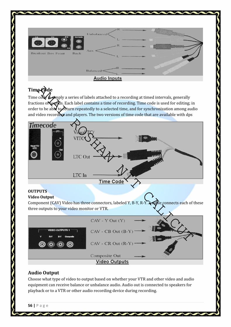
AMAL ROSHAN NIT CALICUT
56 | P a g e
Time Code
Time code is simply a series of labels attached to a recording at timed intervals, generally
fractions of sounds. Each label contains a time of recording. Time code is used for editing; in
order to be able to return repeatedly to a selected time, and for synchronization among audio
and video recorders and players. The two versions of time code that are available with dps
OUTPUTS
Video Output
Component (CAV) Video has three connectors, labeled Y, B-Y, R-Y. A cable connects each of these
three outputs to your video monitor or VTR.
Audio Output
Choose what type of video to output based on whether your VTR and other video and audio
equipment can receive balance or unbalance audio. Audio out is connected to speakers for
playback or to a VTR or other audio recording device during recording.
AMAL ROSHAN NIT CALICUT

AMAL ROSHAN NIT CALICUT
57 | P a g e
3 –D GRAPHICS
THE FIVE MODULES OF SOFTIMAGE
Softimage 3 D Extreme has given different modules that correspond to different
phases of the workflow process you use to create animation. Each of the modules replaces
some of the menu cells on the left and right menu columns, while leaving other menu
cells that are applicable in all modules. The modules are listed along the top right
corner of the screen: Model, Motion, Actor, Matter, and Tools. You can enter these
modules either by clicking the text labels in the top right corner, or by pressing the
supra keys that represent them: F1 for Model, F2 for Motion, F3 for Actor, F4 for Matter, and F5
for Tools.
MODEL
You start your workflow in the Model module, where you construct all your scene
elements. Model's tools enable you to create objects from primitive shapes, draw
curves, and develop surfaces from those curves.
MOTION
You then move to animate some parts of your scene, using the animation tools found in the
Motion module. The Motion module allows you to set animation keyframes for
objects, assign objects to paths, and to see and edit the resulting animation on screen. After
you have refined your animation using the F Curve tools, you move to the next module, Actor.
ACTOR
The Actor module contains the special Softimage tools for setting up virtual actors,
assigning inverse kinematic skeletons, assigning skin, adjusting skeletons deformations, and
weighting the skin to the IK skeletons. Actor also contains the controls for physical-based
animation–Dynamics,Collisions and Qstretch–which is an automatic squash-and-stretch
features.
MATTER
When your modeling, animation, and acting are complete, you move to the fourth module:
Matter. In the Matter module, you assign color and material values to the objects in your scene,
determining how they will look in the final render.
AMAL ROSHAN NIT CALICUT

AMAL ROSHAN NIT CALICUT
58 | P a g e
At any time in the first four modules, you can create lights and adjust their effect on the scene.
The Matter module is also where you perform the last step in the workflow process, rendering.
TOOLS
Tools contains a variety of utility programs for viewing, editing and exporting your work. You
may view individual images, sequences of images, and line tests. You may bring in images
created in other programmes as image maps or import objects created in other programs as
geometry. You can composite sequences of images together, reduce colours in sequences of
images for reduced colour games systems, and move your finished work to video disk recorders
and film recorders.
The Four View Windows
AMAL ROSHAN NIT CALICUT

AMAL ROSHAN NIT CALICUT
59 | P a g e
TELEVISION TRANSMISSION
VESTIGIAL SIDE BAND TRANSMISSION - If normal amplitude modulation technique is used
for picture transmission, the minimum transmission channel bandwidth should be
around 11 MHz taking into account the space for sound carrier and a small guard band of
around 0.25 MHz. Using such large transmission BW will limit the number of channels
in the spectrum allotted for TV transmission. To accommodate large number of
channels in the allotted spectrum, reduction in transmission BW was considered
necessary. The transmission BW could be reduced to around 5.75 MHz by using single side band
(SSB) AM technique, because in principle one side band of the double side band (DSB) AM could
be suppressed, since the two side bands have the same signal content.
Design
All the TV transmitters have the same basic design. They consist of an exciter followed by power
amplifiers which boost the exciter power to the required level.
Exciter
The exciter stage determines the quality of a transmitter. It contains pre-corrector
units both at base band as well as at IF stage, so that after passing through all subsequent
transmitter stages, an acceptable signal is available. Since the number and type of amplifier
stages, may differ according to the required output power, the characteristics of the pre-
correction circuits can be varied over a wide range.
Block Diagram of TV Exciter (Mark-II)
Vision and Sound Signal Amplification
In HPTs the vision and sound carriers can be generated, modulated and amplified separately
and then combined in the diplexer at the transmitter output. In LPTs, on the other hand, sound
and vision are modulated separately but amplified jointly. This is common vision and aural
amplification. A special group delay equalization circuit is needed in the first case because of
errors caused by TV diplexer. In the second case the intermodulation products are more
prominent and special filters for suppressing them is required.As it is difficult to meet the
intermodulation requirements particularly at higher power ratings, separate
AMAL ROSHAN NIT CALICUT
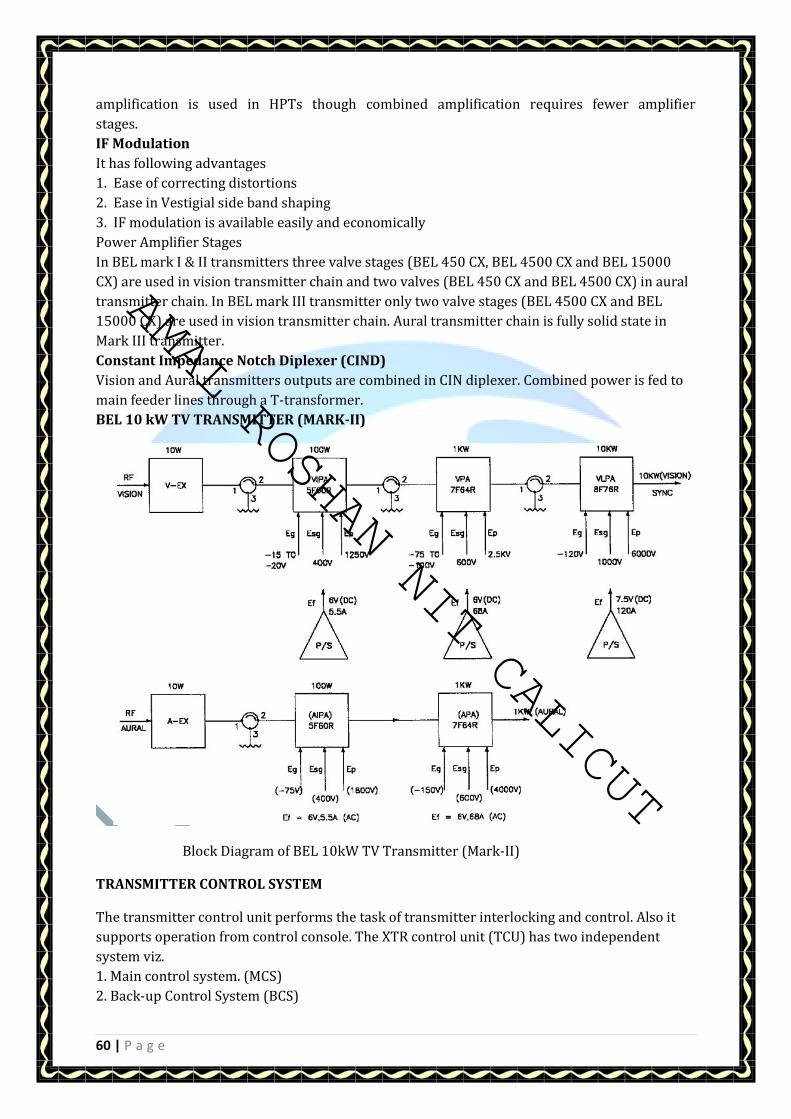
AMAL ROSHAN NIT CALICUT
60 | P a g e
amplification is used in HPTs though combined amplification requires fewer amplifier
stages.
IF Modulation
It has following advantages
1. Ease of correcting distortions
2. Ease in Vestigial side band shaping
3. IF modulation is available easily and economically
Power Amplifier Stages
In BEL mark I & II transmitters three valve stages (BEL 450 CX, BEL 4500 CX and BEL 15000
CX) are used in vision transmitter chain and two valves (BEL 450 CX and BEL 4500 CX) in aural
transmitter chain. In BEL mark III transmitter only two valve stages (BEL 4500 CX and BEL
15000 CX) are used in vision transmitter chain. Aural transmitter chain is fully solid state in
Mark III transmitter.
Constant Impedance Notch Diplexer (CIND)
Vision and Aural transmitters outputs are combined in CIN diplexer. Combined power is fed to
main feeder lines through a T-transformer.
BEL 10 kW TV TRANSMITTER (MARK-II)
Block Diagram of BEL 10kW TV Transmitter (Mark-II)
TRANSMITTER CONTROL SYSTEM
The transmitter control unit performs the task of transmitter interlocking and control. Also it
supports operation from control console. The XTR control unit (TCU) has two independent
system viz.
1. Main control system. (MCS)
2. Back-up Control System (BCS)
AMAL ROSHAN NIT CALICUT

AMAL ROSHAN NIT CALICUT
61 | P a g e
Functions performed by MCS (Main Control System)
- XTR control
- Interlocking
- RF monitoring
- Supporting operation from control console
- Three second logic for protection against sudden fluctuation.
- Thermal protection for 1 kW and 10 kW vision PAs
- Thermal protection for 130 Watt vision PA and Aural XTRa
- Mimic diagram
Functions performed by BCS (Backup control system)
- Transmitting control
- Interlocking
The block diagram of the TCU (Transmitter control unit) indicates the connectivity
of TCU with control console and the control elements of the transmitter. Commands are
inputs through the key board. The control elements are controlled in accordance with
the programme fused in the EPROMS.
Only while operating from the MCS (Main Control System), the interaction with TCU is
supported through a LCD display unit. The LED bar display board showing the status
information, is used by both the MCS and BCS (Back up Control Unit).
Main Control System (MCS) The MCS consists of the following :
1. Mother Board with the following PCBs.
CPU
BIT I/O
Interlock Interface Board (IIB).
Analog I/O Board (AIO)
Control Interface Board (CIB)
Analog Receiver Board (An Rx)
Rectifier and Regulator Board (RRB mcs)
2. Key Board
3. LED Bar Display Board
4. Relay Board
5. LCD Display Unit
6. Transformers T1 and T2 .
7. + 5V/3A. Power Supply Unit.
AMAL ROSHAN NIT CALICUT
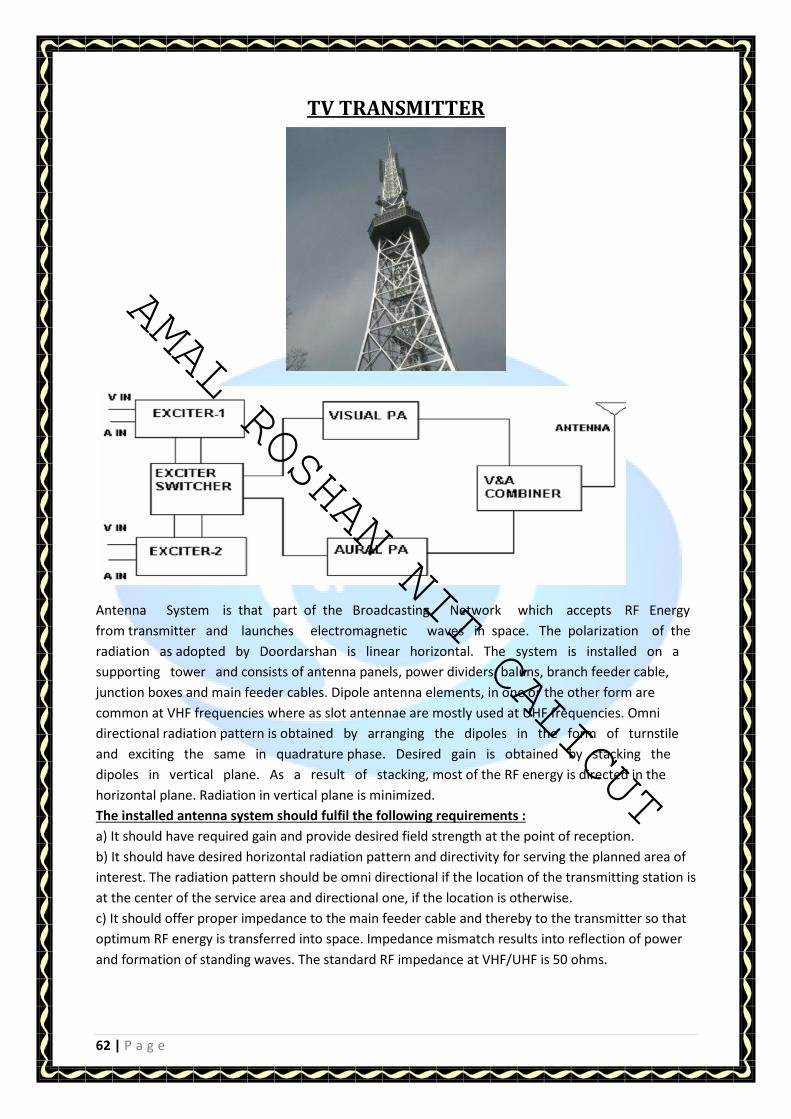
AMAL ROSHAN NIT CALICUT
62 | P a g e
TV TRANSMITTER
Antenna System is that part of the Broadcasting Network which accepts RF Energy
from transmitter and launches electromagnetic waves in space. The polarization of the
radiation as adopted by Doordarshan is linear horizontal. The system is installed on a
supporting tower and consists of antenna panels, power dividers, baluns, branch feeder cable,
junction boxes and main feeder cables. Dipole antenna elements, in one or the other form are
common at VHF frequencies where as slot antennae are mostly used at UHF frequencies. Omni
directional radiation pattern is obtained by arranging the dipoles in the form of turnstile
and exciting the same in quadrature phase. Desired gain is obtained by stacking the
dipoles in vertical plane. As a result of stacking, most of the RF energy is directed in the
horizontal plane. Radiation in vertical plane is minimized.
The installed antenna system should fulfil the following requirements :
a) It should have required gain and provide desired field strength at the point of reception.
b) It should have desired horizontal radiation pattern and directivity for serving the planned area of
interest. The radiation pattern should be omni directional if the location of the transmitting station is
at the center of the service area and directional one, if the location is otherwise.
c) It should offer proper impedance to the main feeder cable and thereby to the transmitter so that
optimum RF energy is transferred into space. Impedance mismatch results into reflection of power
and formation of standing waves. The standard RF impedance at VHF/UHF is 50 ohms.
AMAL ROSHAN NIT CALICUT

AMAL ROSHAN NIT CALICUT
63 | P a g e
Outdoor Broadcasting Van (OB Van)
O B Van (Outdoor Broadcasting van )- OB van is used for live broadcasting like any match or any
event. It consist all the equipments that is present in the studio for telecasting. It also referring as
mini studio . It has mainly 3 parts :
1)Power supply unit
2)Production control unit
3)Audio console and VTR
Inner View of OB van
Inner View of OB van
AMAL ROSHAN NIT CALICUT

AMAL ROSHAN NIT CALICUT
64 | P a g e
EARTH STATION
SATELLITE COMMUNICATION Satellite Communication is the outcome of the desire of man to achieve the concept of global village.
Penetration of frequencies beyond 30 Mega Hertz through ionosphere force people to think that if
an object (Reflector) could be placed in the space above ionosphere then it could be possible to use
complete spectrum for communication purpose.
Intelsat-I (nick named as Early Bird) was launched on 2 April 1965. This was parked
in geosynchronous orbit in Atlantic ocean and provided telecommunication or
television service between USA and Europe. It had capacity for 240 one way telephone
channels or one television channel. Subsequently Intelsat-II generation satellites were launched
and parked in Atlantic ocean and Pacific Ocean. During Intelsat III generation, not only Atlantic and
Pacific ocean got satellites but also Indian Ocean got satellite for the first time. Now Arthur
C.Clarke's vision of providing global communication using three Satellites with about 120 degrees
apart became a reality. So far Intelsat has launched 7 generations of geosynchronous
satellites in all the three regions namely Atlantic Ocean, Pacific Ocean and Indian Ocean.
For national as well as neighbouring countries coverage, some of the following satellites are used:
ANIK : Canadian satellite system I
NSAT : Indian Satellites
AUSSAT : Australian Satellites
BRAZILSAT : Brazilian Satellites
FRENCH TELECOM : French Satellites
ITALSAT : Italian Satellites
CHINASAT : Chinese Satellites
STATSIONAR, GORIZONT, Russian Satellites
Architecture of a Satellite Communication System
The Space Segment
The space segment contains the Satellite and all terrestrial facilities for the control and monitoring of
the Satellite. This includes the tracking, telemetry and command stations (TT&C) together with the
Satellite control centre where all the operations associated with station-keeping and checking the
vital functions of the satellite are performed. In our case it is Master Control Facility (MCF) at
Hassan.
The radio waves transmitted by the earth stations are received by the satellite ; this is called the up
link. The satellite in turn transmits to the receiving earth stations ; this is the down link. The quality
of a radio link is specified by its carrier-to-noise ratio. The important factor is the quality of the total
link, from station to station, and this is determined by the quality of the up link and that of the down
link. The quality of the total link determines the quality of the signals delivered to the end user in
accordance with the type of modulation and coding used.
AMAL ROSHAN NIT CALICUT
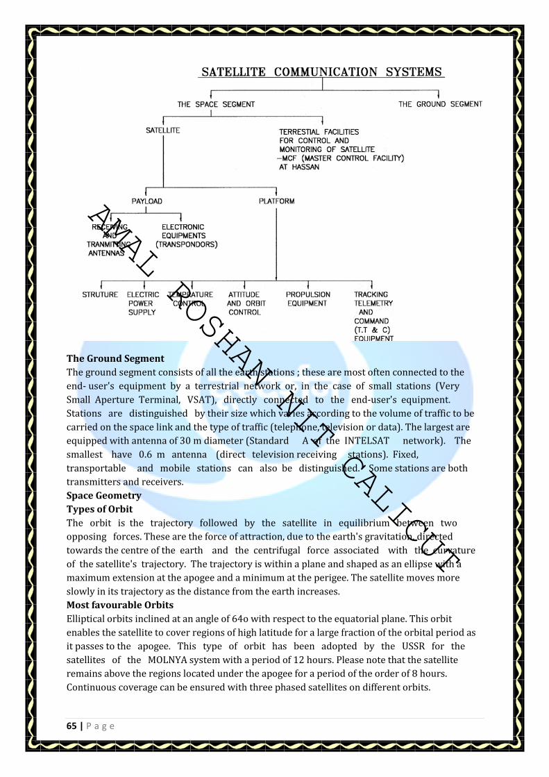
AMAL ROSHAN NIT CALICUT
65 | P a g e
The Ground Segment
The ground segment consists of all the earth stations ; these are most often connected to the
end- user's equipment by a terrestrial network or, in the case of small stations (Very
Small Aperture Terminal, VSAT), directly connected to the end-user's equipment.
Stations are distinguished by their size which varies according to the volume of traffic to be
carried on the space link and the type of traffic (telephone, television or data). The largest are
equipped with antenna of 30 m diameter (Standard A of the INTELSAT network). The
smallest have 0.6 m antenna (direct television receiving stations). Fixed,
transportable and mobile stations can also be distinguished. Some stations are both
transmitters and receivers.
Space Geometry
Types of Orbit
The orbit is the trajectory followed by the satellite in equilibrium between two
opposing forces. These are the force of attraction, due to the earth's gravitation, directed
towards the centre of the earth and the centrifugal force associated with the curvature
of the satellite's trajectory. The trajectory is within a plane and shaped as an ellipse with a
maximum extension at the apogee and a minimum at the perigee. The satellite moves more
slowly in its trajectory as the distance from the earth increases.
Most favourable Orbits
Elliptical orbits inclined at an angle of 64o with respect to the equatorial plane. This orbit
enables the satellite to cover regions of high latitude for a large fraction of the orbital period as
it passes to the apogee. This type of orbit has been adopted by the USSR for the
satellites of the MOLNYA system with a period of 12 hours. Please note that the satellite
remains above the regions located under the apogee for a period of the order of 8 hours.
Continuous coverage can be ensured with three phased satellites on different orbits.
AMAL ROSHAN NIT CALICUT

AMAL ROSHAN NIT CALICUT
66 | P a g e
Circular inclined orbits :
The altitude of the satellite is constant and equal to several hundreds of kilometers. The period
is of the order of one and a half hours. With near 90% inclination this type of orbit guarantees
that the satellite will pass over every region of the earth. Several systems with world wide
coverage using constellations of satellite carries in low altitude circular orbits are for e.g.
IRIDIUM, GLOBAL STAR, ODYSSEY, ARIES, LEOSAT, STARNET, etc.
Circular orbits
with zero inclination (Equatorial orbits). The most popular is the geo stationary satellite orbits ;
the satellite orbits around the earth at an altitude of 35786 km, and in the same direction as the
earth. The period is equal to that of the rotation of the earth and in the same direction. The
satellite thus appears as a point fixed in the sky and ensures continuous operation as a radio
relay in real time for the area of visibility of the satellite (43% of the earth's surface).
Factors deciding the selection of Orbit
The choice of orbit depends on the nature of the mission, the acceptable
interference and the performance of the launchers :
The extent and latitude of the area to be covered.
The elevation angle of earth stations.
Transmission duration and delay.
Interference
The performance of launchers
TVRO System
Presently Doordarshan is up linking its national, metro and regional services to INSAT-2A (74oC) and
INSAT-2B (93.5oE) and INSAT 2E (83o C). Down link frequency bands being used are C-Band (3.7-4.2
GHz) and Ex-C Band (4.5-4.8 GHz).
Transmission of base band to Satellite
The base band signal consists of video (5 MHz), two audio subcarriers (5.5 MHz & 5.75 MHz) and
energy dispersal signal (25 Hz). After modulation (70 MHz) and upconversion (6 GHz) the carrier is
amplified and uplinked through Solid Parabolic Dish Antenna (PDA). Down link signal can be received
through same PDA using Trans-Receive Filter (TRF) and Low Noise Amplifier (LNA). After down
conversion to 70 MHz, it is demodulated to get audio and video.
AMAL ROSHAN NIT CALICUT

AMAL ROSHAN NIT CALICUT
67 | P a g e
Satellite Transponder
As shown in fig, the uplinked signal (6 GHz) at satellite is received, amplified and down converted to
4 GHz band and sent back through filter and power amplifier (TWT). The local oscillator frequency of
down converter is 2225 MHz for C band and Ex-C band transponders.
Block Diagram of Satellite Transponder
Receiving Satellite Signal
For receiving a satellite signal we need following equipment :
1. Satellite receiving antenna (PDA).
2. Feed with low noise block converter (LNBC).
3. Indoor unit consisting of satellite system unit and a Synthesised satellite receiver.
Parallels of Latitudes Latitude as Angular Distance
AMAL ROSHAN NIT CALICUT

AMAL ROSHAN NIT CALICUT
68 | P a g e
Direct-to-Home Satellite Broadcasting (DTH)
INTRODUCTION
There was always a persistent quest to increase the coverage area of broadcasting.
Before the advent of the satellite broadcasting, the terrestrial broadcasting, which is
basically localized, was mainly providing audio and video services. The terrestrial broadcasting has
a major disadvantage of being localized and requires a large number of transmitters to cover a big
country like India. It is a gigantic task and expensive affair to run and maintain the large number of
transmitters. Satellite broadcasting, came into existence in mid sixties, was thought to
provide the one-third global coverage simply by up-link and down-link set-ups. In the
beginning of the satellite broadcasting, up-linking stations (or Earth Stations) and satellite
receiving centers could had only been afforded by the Governments organizations. The main
physical constraint was the enormous size of the transmitting and receiving parabolic
dish antennas (PDA). In the late eighties the satellite broadcasting technology had
undergone a fair improvements resulting in the birth of cable TV. Cable TV operators set
up their cable networks to provide the services to individual homes in local areas. It rapidly grew
in an unregulated manner and posed a threat to terrestrial broadcasting. People are now
mainly depending on cable TV operators. Since cable TV services are unregulated and unreliable in
countries like India now, the satellite broadcasting technology has ripened to a level where
an individual can think of having direct access to the satellite services, giving the
opportunity to viewers to get rid of cable TV. Direct-to-Home satellite broadcasting (DTH) or Direct
Satellite Broadcasting (DBS) is the distribution of television signals from high powered
geo- stationary satellites to a small dish antenna and satellite receivers in homes across the country.
The cost of DTH receiving equipments is now gradually declining and can be afforded by common
man. Since DTH services are fully digital, it can offer value added services, video-on-demand,
Internet, e- mail and lot more in addition to entertainment. DTH reception requires a small dish
antenna (Dia 60 cm), easily be mounted on the roof top, feed along with Low Noise Block Converter
(LNBC), Set- up Box (Integrated Receiver Decoder, IRD) with CAS (Conditional Access System). A
bouquet of 40 to 50 video programs can simultaneously be received in DTH mode.
UPLINK CHAIN
DTH broadcasting is basically satellite broadcasting in Ku-Band (14/12 GHz). The main advantage of
Ku-Band satellite broadcasting is that it requires physically manageable smaller size of
dish antenna compared to that of C-Band satellite broadcasting. C-Band broadcasting requires about
3.6 m dia PDA (41dB gain at 4 GHz) while Ku-Band requires 0.6 m dia PDA (35dB gain at 12 GHz). The
shortfall of this 6 dB is compensated using Forward Error Correction (FEC), which can offer 8 to 9 dB
coding gain in the digital broadcasting. Requirement of transmitter power (about 25 to
50 Watts) is less than that of analog C-band broadcasting. The major drawback of
Ku-Band transmission is that the RF signals typically suffer 8 to 9dB rain attenuation under heavy
rainfall while rain attenuation is very low at C-Band. Fading due to rain can hamper
the connectivity of satellite and therefore rain margin has to be kept for reliable connectivity. Rain
margin is provided by operating transmitter at higher powers and by using larger size of the dish
antenna (7.2m PDA). Fig.1 shows schematic of uplink chain proposed to broadcast
bouquet of 30 video programs in Doordarshan, Prasar Bharati, India. 30 video programs may
AMAL ROSHAN NIT CALICUT

AMAL ROSHAN NIT CALICUT
69 | P a g e
either be down-linked from satellites or taken from other sources like video tape recorders, video
cameras etc. in digital format. These sources are fed to Router whose outputs are divided in three
groups A, B and C. Each group contains 10 video sources multiplexed in a Multiplexer. These three
multiplexed streams are digitally (QPSK modulation) modulated individually at 70 MHz Intermediate
Frequency (IF). Each group is further doubly up-converted, first conversion at L-Band (950-1450
MHz) and second conversion at Ku-Band (12-14 GHz).
DOWN-LINK CHAIN
Down-Link or receiving chain of DTH signal is depicted in Fig.2. There are mainly three
sizes of receiving antenna, 0.6m, 0.9m, and 1.2m. Any of the sizes can easily be
mounted on rooftop of a building or house. RF waves (12.534GHz, 12.647GHz, 12.729 GHz) from
satellite are picked up by a feed converting it into electrical signal. The electrical signal is
amplified and further down converted to L-Band (950-1450) signal. Feed and LNBC are
now combined in single unit called LNBF. The L-Band signal goes to indoor unit, consisting a
set-top box and television through coaxial cable. The set-top box or Integrated Receiver
Decoder (IRD) down converts the L-Band first IF signal to 70 MHz second IF signal,
perform digital demodulation, de-multiplexing, decoding and finally gives audio/video output
to TV for viewing.
AMAL ROSHAN NIT CALICUT

AMAL ROSHAN NIT CALICUT
70 | P a g e
AMAL ROSHAN NIT CALICUT

AMAL ROSHAN NIT CALICUT
AMAL ROSHAN NIT CALICUT
AMAL ROSHAN NIT CALICUT