design of fir ls hibert through fuliband differentiators · · 2009-03-05design offir ls hibert...
TRANSCRIPT
Design of FIR LS Hibert Transformers ThroughFuliband Differentiators
Guergana Mollova*
Institute of Communications and Radio-Frequency EngineeringVienna University of Technology
Gusshausstrasse 25/389, A-1040 Vienna, AustriaE-mail: [email protected]
Abstract-This paper presents some new explicit expressions forthe impulse responses of the Case 3, Case 4, and differentiatingHilbert transformers. The proposed closed-form design is basedon the fullband least-squares differentiator and relations betweendifferentiator and Hilbert transformer. The obtained simpleformulas give an efficient way to determine tap-coefficients ofdesigned Hilbert transformers even with a hand calculator.Several numerical examples and comparison with McClellan-Parks algorithm prove the efficiency of this approach.
I. INTRODUCTION
The Hilbert transformers (HTs) have various applications,namely in speech and image processing, signal modulation,radar techniques, seismic signal processing, etc. Among themost popular approaches for design of HTs are the McClellan-Parks algorithm [1], eigenfilter method [2], and least-squaresapproach [3]. Several interrelations between digital one/halfband filters, low/high order digital differentiators, anddiscrete/differentiating HTs are discussed in [4]. Other usefulrelationships are also given in [5-7]. New designs of discreteand differentiating HTs are presented in [8] using their relationwith the Taylor series based differentiators. Some other explicitexpressions for the impulse response of maximally flat FIRHTs are derived in [9-1 1]. Le Bihan [9], for example, proposesan efficient algorithm for calculation the coefficients ofmaximally flat (for midband frequencies) HTs anddifferentiators. As a result, new closed-form explicit andrecursive formulas are derived. A different approach formaximally flat HTs using Taylor configuration is shown in[10]. Further, Khan and Okuda [11] proposed new designs ofeven and odd length HTs by transforming a design ofdifferentiators with flat magnitude response. Thus, the obtainedHTs have relatively narrow transition bands compared to theexisting maximally flat designs. The fractional maximally flatFIR HTs are further designed in [12], together with someefficient hardware realization structures. An additionalcontribution to the problem is given in [13], including a closed-form design of maximally flat FIR HTs, differentiators andfractional delayers based on power series expansion. Efficientimplementation structures based on the simple forms ofweighting coefficients are also presented.An application of the Hopfield-type neural network for
The author is on leave of absence from the Dept. of Computer-Aided Eng.,University of Architecture, Civil Eng. and Geodesy, 1 Hr. Smirnenski Blvd.,1046 Sofia, Bulgaria
design of HTs and digital differentiators is shown in [14].Using the frequency-response masking technique and therelationship between a halfband filter and a transformer, Limand Yu [15] considered a synthesis of new very sharp HTs.The aim of this work is to derive several explicit formulas
for the tap-coefficients of FIR Hilbert transformers, which willbe obtained through fullband least-squares (LS) differentiator.As a starting point we use the exact expressions for the impulseresponse of a fullband differentiator [16] and interrelations [4].The problem is stated in Section II. The derivation of the newrelations for Case 3/Case 4 HTs and differentiating HTs isshown in Section III and Section IV of this work, respectively.Our examination will finish with some simulation results andconclusions (Section V).
II. PROBLEM FORMULATION
The ideal frequency response HIjT of a Hilbert transformeris [2,3]:
where
(1)HT (ej)) = DHT(a)).eiz 2
DHT () {-1: C z< 0< C2
1, -)C2 < )j < -)JC1and Wcl and WC2 are the lower and upper edge frequencies,respectively. Either Case 3 or Case 4 antisymmetric FIRimpulse response sequences can be used to approximate theideal frequency response (1).The frequency response ofthis kind of FIR filter is:
H(ejw ) = M(co).ej(z 2 w(N 1)2where M( ) is real valued, given by:
{(N-1)12Z b(n) sin nco, N odd (Case 3)
M(0o) = N12l b(n) sin(n -1 / 2)0, N even (Case 4)n=l
(2)
(3)
and b(n) can be expressed as a function of the tap-coefficients[3].For the design of linear-phase first-order digital
differentiators (DDs), the impulse response d(n) is alsoantisymmetric [2,3]. Therefore, we have d(n)=-d(N-1-n)and d((N -1)/ 2) = 0 (for N odd) and the transfer function is:
978-1-4244-2110-7/08/$25.00 C2007 IEEE 1121
Authorized licensed use limited to: IEEE Xplore. Downloaded on March 5, 2009 at 03:54 from IEEE Xplore. Restrictions apply.
N-1
H(z) = E d(n).z- (4)n=O
The ideal DD has the following frequency response:
HI' (ejco) D (co).eif , (5)whereDDD(CO) Co for O.<.<or <z and c denotes thepassband edge frequency of a differentiator.
It is shown [16], that for first-order fullband DD (N even,c=z) designed by LS method the following compact relationfor the coefficients b(n) from (3) could be derived:
8.( n+1 <N<b(n) = .(2n ) < n <2For clarity, we introduce below an integer t instead of n.
Using the fact that:
b(t)=2dN-t) 1<t N
we can write the expressions for the impulse response of thefullband LS DD (obtained as a result of the method [16]) as:
N t) N 4.( 1)t, 1<t< N (6)2 2 zz.(2t 1) 2
By that means, the need to solve the system of linear equationsfor the case of fullband DD [16] is avoided. Below, we presentnew designs of even and odd length HTs by transforming anexisting design of fullband DDs (6), which is obtained usingthe LS method.
III. DESIGN OF FIR CASE 3 AND CASE 4 HILBERT TRANSFORMERS
The following relation between the coefficients of Case 3 HTand d(n) is given in [4]:
h (n) J(1)( N) 2.[(N-1)12-n 2]d(n 2), n even (7)1 0, n odd,
2(N-1)where the transfer function is: H3 (z)= E h3 (n).z-n and N is
n=O
the length of differentiator (see Fig. 1). The length of obtainedCase 3 Hilbert transformer is therefore 2N-1.We would like to express the tap-coefficients h3(n) as a
function of d N t in order to use the known relation (6).t2 N
Therefore, we set n = N_t for 1 < t < N and obtain:2 2 2
h3(N -2t)= (1) 2t dN -t, N-2t even (8)Taking into account that N-2t is always an even number for tinteger and fullband DD (N even), and using equations (6) and(7), we get:
2 Nh3(N-2t) =h3(N-2+2t) 1<t<2zr(2t 1) 2 (9)
1 35 Ni1h3(N- 2r) h3(N- 2±+2r) =tr,.. 2 22 2
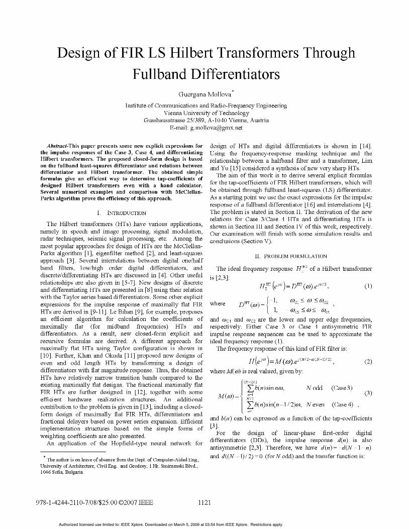
Hilbert Case 3 transformer2(N-1)
H3 (z)= k(n).-n=O
2N- 1: length of Hilbert Case 3transformer (odd)
First-order fullband Case 4 Hilbert Case 4 transformerdifferentiator N-1
NH( -n H4 (z) h4 (n) .z-nH(z) Yd(n).Z n=O
n=O N: length of Hilbert Case 4N: length of differentiator transformer (even)
(even)
Differentiating Hilberttransformer
2(N-1)HD(z) = hD (n) Z
n=O
2N-1: length of differentiatingHilbert transformer (odd)
Fig. 1. Design transformations.
The last formula gives a very simple expression for thecoefficients of Case 3 HT designed through fullband Case 4DD with length N. As we have started our design from fullbandLS DD, we can conclude now, that the Hilbert transformer (9)also possesses least-squares features. Indeed, the examplesgiven in Section V clearly show typical LS magnituderesponses of designed Hilbert transformers.
The second equation from (9) corresponds to inserting a zerobetween every two successive coefficients, i.e. h3(n)=O when nis odd number (n=1,3,5,...,2N-3).
If we remove the zero-valued samples of the Case 3 LS HTexpressed by (9), we will further obtain Case 4 LS HT.Reference [4] proposed the following relation for even-lengthHT:
h4(n) = h3(2n) ((1)-N) 2N 1n)Jd(n), O<n<N-1 (10)N-1
which transfer function is: H4(z) = h4(n).z -n=O
From (6) and (10), it is easy to derive the following newrelation for Case 4 HT designed by LS technique:
h4C 2 4h( 21+t)2 N * (11)
;T(2t - 1) 2
It is clear, that he total number of non-zero impulse responsecoefficients (and therefore the computational complexity) ofdesigned Case 4 HTs is the same as this one of the fullbandDDs (for N even number).As an example, we have designed the resulting HTs for
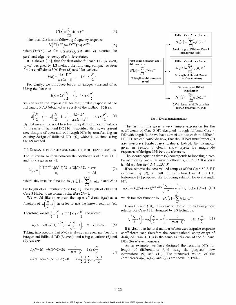
length of differentiator N=6 using the proposed newexpressions (9) and (11). The numerical values of thecoefficients d(n), h3(n), and h4(n) are shown in Table I.
1122
Authorized licensed use limited to: IEEE Xplore. Downloaded on March 5, 2009 at 03:54 from IEEE Xplore. Restrictions apply.
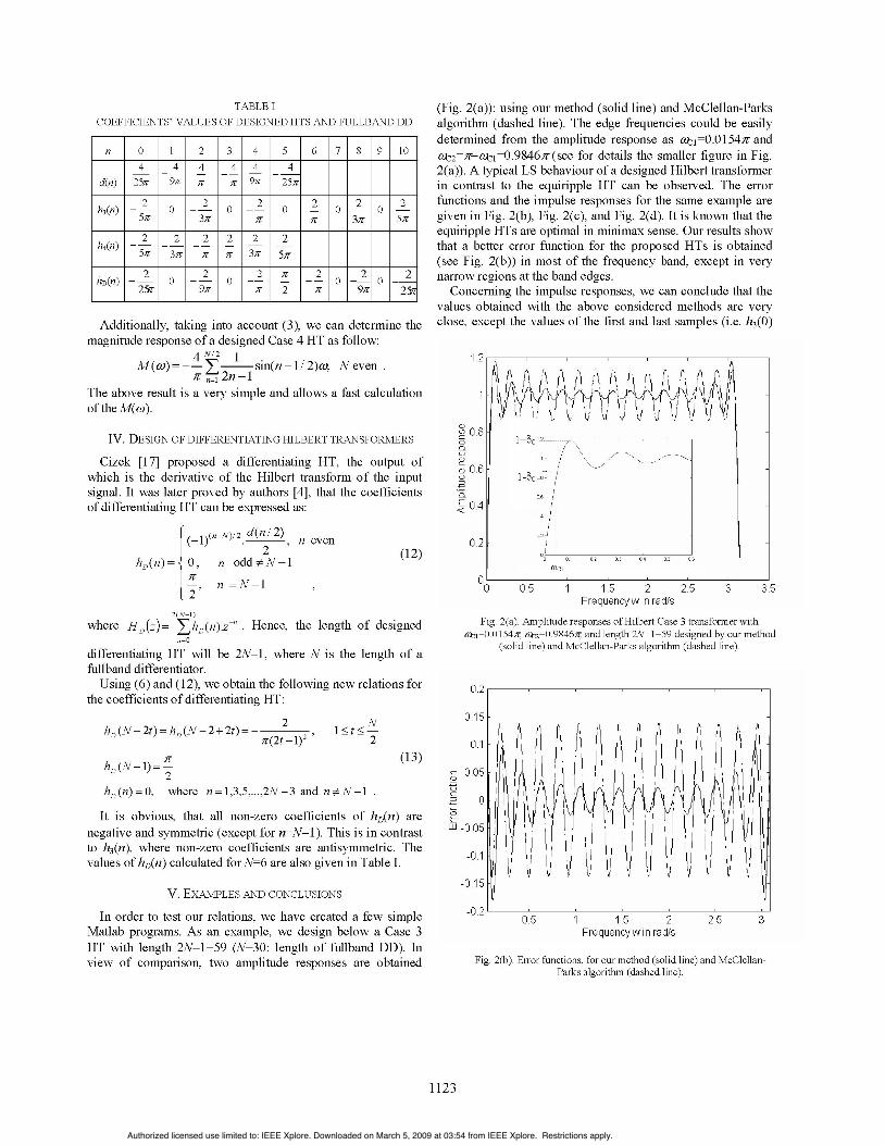
TABLE ICOEFFICIENTS' VALUES OF DESIGNED HTS AND FULLBAND DD
n 0 1 2 3 4 5 6 7 8 9 104 4 4 4 4 4
d(n) 25fT 9r 4T 4 9;f 25fT
2 2 2 2 2 2h3(n) 0 0 0 0 0
5ff 3fT if 3fT 5/v
h4(n) 2 2 2 2 2 2
hD(n) 20 2 02 2 2 O 2 O 22'T 9ff ff 2 if 9ff 25
Additionally, taking into account (3), we can determine themagnitude response of a designed Case 4 HT as follow:
4 N12 I
M(n)) = --E sin(n - 1/ 2)w, N evenZ n=1 2n-1
The above result is a very simple and allows a fast calculationof the M(Z).
IV. DESIGN OF DIFFERENTIATING HILBERT TRANSFORMERS
Cizek [17] proposed a differentiating HT, the output ofwhich is the derivative of the Hilbert transform of the inputsignal. It was later proved by authors [4], that the coefficientsof differentiating HT can be expressed as:
(-1)(fN) 2 d(n / 2) n even
hD(n)= {, n odd#N-1
t 'n =N-1
(Fig. 2(a)): using our method (solid line) and McClellan-Parksalgorithm (dashed line). The edge frequencies could be easilydetermined from the amplitude response as ctj0=0154fz andfC2=Z-ctj=0.9846z (see for details the smaller figure in Fig.
2(a)). A typical LS behaviour of a designed Hilbert transformerin contrast to the equiripple HT can be observed. The errorfunctions and the impulse responses for the same example aregiven in Fig. 2(b), Fig. 2(c), and Fig. 2(d). It is known that theequiripple HTs are optimal in minimax sense. Our results showthat a better error function for the proposed HTs is obtained(see Fig. 2(b)) in most of the frequency band, except in verynarrow regions at the band edges.
Concerning the impulse responses, we can conclude that thevalues obtained with the above considered methods are veryclose, except the values of the first and last samples (i.e. h3(0)
1.2
01)LO 0.8
K050n
T 0.6
E 0.4
(12)
0.
2(N-1)where HD(z) ZhD (n).z Hence, the length of designed
n=O
differentiating HT will be 2N-1, where N is the length of afullband differentiator.
Using (6) and (12), we obtain the following new relations forthe coefficients of differentiating HT:
hD(N - 2t) = hD(N - 2 + 2t)2 N
ir(2t - 1)2'I1< < 2
hD(N - =-
hD(n)= 0, where n =1,3,5,...,2N -3 and n.N-I
(13)o
0III9
It is obvious, that all non-zero coefficients of hD(n) arenegative and symmetric (except for n=N- ). This is in contrastto h3(n), where non-zero coefficients are antisymmetric. Thevalues of hD(n) calculated for N=6 are also given in Table I.
V. EXAMPLES AND CONCLUSIONS
In order to test our relations, we have created a few simpleMatlab programs. As an example, we design below a Case 3HT with length 2N-1=59 (N=30: length of fullband DD). Inview of comparison, two amplitude responses are obtained
1.5 2Frequencyw in radls
Fig. 2(a). Amplitude responses of Hilbert Case 3 transformer witha =0.0l54T, O2=0.9846ff, and length 2N-1=59 designed by our method
(solid line) and McClellan-Parks algorithm (dashed line).
0.5 1 1.5 2Frequencyw in rad/s
Fig. 2(b). Error functions, for our method (solid line) and McClellan-Parks algorithm (dashed line).
1123
Authorized licensed use limited to: IEEE Xplore. Downloaded on March 5, 2009 at 03:54 from IEEE Xplore. Restrictions apply.
and h3(2N-2), see Fig. 2(c) , Fig. 2(d)).The amplitude response of designed differentiating HT with
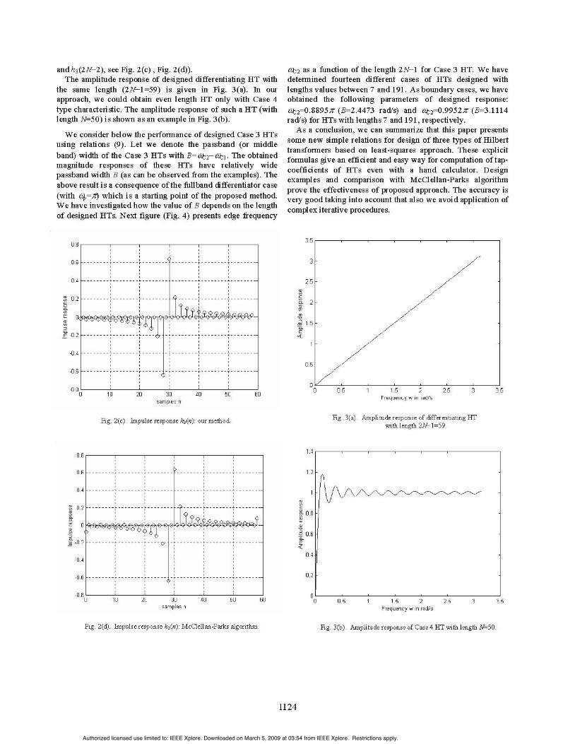
the same length (2N-1=59) is given in Fig. 3(a). In ourapproach, we could obtain even length HT only with Case 4type characteristic. The amplitude response of such a HT (withlength N=50) is shown as an example in Fig. 3(b).
We consider below the performance of designed Case 3 HTsusing relations (9). Let we denote the passband (or middleband) width of the Case 3 HTs with B=C02-ot. The obtainedmagnitude responses of these HTs have relatively widepassband width B (as can be observed from the examples). Theabove result is a consequence of the fullband differentiator case(with q=;r) which is a starting point of the proposed method.We have investigated how the value ofB depends on the lengthof designed HTs. Next figure (Fig. 4) presents edge frequency
nu.o
0.G
04
02
o6
-0.2
-0.4
-O6
J.b0 10 20 30 40 50 60
samples n
Fig. 2(c). Impulse response h3(n): our method.
0.8
0.2Ei L L-r - - - - - - - - -r- - - - - - - - r - - - - - - - --
66E>
64.2
0 10l 26 30 40 50 6samples n
Ctz2 as a function of the length 2N-1 for Case 3 HT. We havedetermined fourteen different cases of HTs designed withlengths values between 7 and 191. As boundary cases, we haveobtained the following parameters of designed response:0t{2=0-8895T (B=2.4473 rad/s) and O12=O.9952r (B=3.1114rad/s) for HTs with lengths 7 and 191, respectively.As a conclusion, we can summarize that this paper presents
some new simple relations for design of three types of Hilberttransformers based on least-squares approach. These explicitformulas give an efficient and easy way for computation of tap-coefficients of HTs even with a hand calculator. Designexamples and comparison with McClellan-Parks algorithmprove the effectiveness of proposed approach. The accuracy isvery good taking into account that also we avoid application ofcomplex iterative procedures.
CD
co
cor
.- 1 .5
0.5
0 0(5 1 15 2 25 3Frequency w in rad/s
Fig. 3(a). Amplitude response of differentiating HTwith length 2N-1=59.
0 0.5 1 15 2Frequency w in rad/s
Fig. 2(d). Impulse response h3(n): McClellan-Parks algorithm. Fig. 3(b). Amplitude response of Case 4 HT with length N=50.
1124
J.DR
n -
0
ZD7
-n-u
Authorized licensed use limited to: IEEE Xplore. Downloaded on March 5, 2009 at 03:54 from IEEE Xplore. Restrictions apply.

3.15
-F
I 2.95O-
a) 2.9
L)
2.75 L0 100
2N-1150
Fig. 4. Edge frequency 09C2 as a function of the length of a HilbertCase 3 transformer for the proposed method.
REFERENCES
[1] J.H. McClellan, T.W. Parks, and L.R. Rabiner, "A computer program fordesigning optimum FIR linear phase digital filters", IEEE Trans. AudioElectroacoust., vol. 21, pp. 506-526, Dec. 1973.
[2] S.-C. Pei and J.-J. Shyu, "Design of FIR Hilbert transformers anddifferentiators by eigenfilter", IEEE Trans. Circuits Syst., vol. 35, pp.1457-1461, Nov. 1988.
[3] S. Sunder and V. Ramachandran, "Design of equiripple nonrecursivedigital differentiators and Hilbert transformers using a weighted least-squares technique", IEEE Trans. Signal Process., vol. 42, pp. 2504-2509,Sept. 1994.
[4] S.-C. Pei and J.-J. Shyu, "Relationships among digital one/half bandfilters, low/high order differentiators, and discrete/differentiating Hilbert
transformers", IEEE Trans. Signal Process., vol. 40, pp. 694-700, March1992.
[5] B. Kumar, S.C. Dutta Roy, and S. Sabharwal, "Interrelations between thecoefficients of FIR digital differentiators and other FIR filters and aversatile multifunction configuration", Signal Process., vol. 39, pp. 247-262, 1994.
[6] S.C. Dutta Roy and B. Kumar, "On digital differentiators, Hilberttransformers, and half-band low-pass filters", IEEE Trans. Education,vol. 32, pp. 314-318, Aug. 1989.
[7] H.W. Schussler and P. Steffen,"Halfband filters and Hilbert transformers",Circuits, Systems, Signal Process., vol. 17, pp. 137-164, Feb. 1998.
[8] I.R. Khan and R. Ohba, "New efficient design of discrete anddifferentiating FIR Hilbert transformjers", IEICE Trans. Fundamentals,vol. E83-A, pp. 2736-2738, Dec. 2000.
[9] J. Le Bihan, "Coefficients of FIR digital differentiators and Hilberttransformers for midband frequencies", IEEE Trans. Circuits Syst. - partII: Analog and digital signalprocess., vol. 43, pp. 272-274, March 1996.
[10] B. Kumar and G. Gabrani, "Design of maximally flat FIR Hilberttransformers as Taylor realizations", Int. Journal Circuit Theory Appl.,vol. 27, pp. 474-454, 1999.
[11] I.R. Khan and M. Okuda, "Narrow transition band FIR Hilberttransformers with flat magnitude response", IEEE Signal Process. Letters,vol. 14, pp. 613-616, Sept. 2007.
[12] S.-C. Pei and P.-H. Wang, "Analytical design of maximally flat FIRfractional Hilbert transformers", Signal Process., vol. 81, pp. 643-661,2001.
[13] S.-C. Pei and P.-H. Wang, "Closed-form design of maximally flat FIRHilbert transformers, differentiators, and fractional delayers by powerseries expansion", IEEE Trans. Circuits Syst. - part I: Fundamentaltheory and applications, vol. 48, pp. 389-398, Apr. 2001.
[14] D. Bhattacharya and A. Antoniou, "Design of digital differentiators andHilbert transformers by Feedback Neural Networks", Proc. IEEE PacificRim Conf: Comm., Comp. Signal Process., Victoria, BC, pp. 489-492, 17-19 May 1995.
[15] Y.C. Lim and Y.J. Yu, "Synthesis of very sharp Hilbert transformer usingthe frequency-response masking technique", IEEE Trans. SignalProcess., vol. 53, pp. 2595-2597, July 2005.
[16] G. Mollova, "Compact formulas for least-squares design of digitaldifferentiators", Electronics Letters, vol. 35, pp. 1695-1697, Sept. 1999.
[17] V.V. Cizek, "Differentiating FIR Hilbert transformer". Proc. URSI Int.Symp. Signals, Syst., Electron., Erlangen, Germany, pp. 697-700, Sept.1989.
1125
- -
- -
- ---
Authorized licensed use limited to: IEEE Xplore. Downloaded on March 5, 2009 at 03:54 from IEEE Xplore. Restrictions apply.