creating rapport with virtual humansict.usc.edu/pubs/ict-tr.02.2006-rick.pdf · solid conclusion...
TRANSCRIPT

Creating Rapport with Virtual Humans
R.J. van der Werf 1, 2
1University of Twente, Department of Computer Science
2University of Southern California, Institute for Creative Technologies
ICT Technical Report No: ICT TR 02.2006
ICT Emotions Project
Preface An important part of my Computer Science studies at the University of Twente is a 14 week internship, which has to be completed before the final master research. This internship can be done inside the Netherlands as well as abroad. Thanks to Anton Nijholt I was able to do my internship abroad at the Institute of Creative Technologies. This institute is a research institute of the University of Southern California. During my internship I, together with two other interns (SLT Morales, SLT Lamothe) from France, continued the work of R.M. Maatman under the guidance of Jonathan Gratch. This report will mainly focus on my work during this period and, where applicable, the work of the two other interns, since we worked on one project: Building Rapport with Virtual Humans. My focus within this project lies on the detection of gestures; the testing of the whole system is another important issue.
Because the whole internship abroad proofed to be quite an experience, professionally as well as personally, I would like to thank Deethra Roulac and Jonathan Gratch for making my visit to the United States possible. I’d also like to thank Martijn Maatman for providing me with useful information about what to expect and how to arrange certain things before going to the United States. Thanks to Edward Fast for his guidance throughout the whole internship, to Ashok Basawapatna for supporting me with Smartbody, to Aaron Hill for assisting me with Maya, to Stacy Marsella for giving his insights and assistance and Scott Rocher for his assistance with Final Cut Pro. Special thanks to Louis- Philippe Morency and Ronald Poppe for the support with their software which they made available to ICT. My personal and professional thanks go out to Patrick Kenny and Arno Hartholt for assistance during my internship and especially for giving me the opportunity to test the SASO system inside the VR Theater. Personally I’d also like to thank Martin van Velsen for lending his bicycle to me and Arno Hartholt for the great opportunity to be his roommate.
This work was sponsored by the U. S. Army Research, Development, and Engineering Command (RDECOM). The content does not necessarily reflect the position of the policy of the Government, and no official endorsement should be inferred.
Abstract This report describes the internship about the assignment Creating Rapport with Virtual Humans. The assignment is split up into two separate parts. The first part is to improve the visual feature detection of the current mimicking system [MAA04]. This is going to be done using a Computer Vision approach. Together with two other interns [LAM05] the whole mimicking system was improved, leading to a new Rapport system. The second part involves subject testing with the newly developed system.
Firstly the goal is to make a working system that can be reused and expanded in the future. Secondly the goal is to use the data from the subject test to determine if rapport can be created with Virtual Humans.
The resulting Rapport system should be a very well reuseable and expandable system. This system makes it possible for other people, unfamiliar with the system, to easily use the system for future testing. Unfortunately too little data was obtained with subject testing to give a solid conclusion whether or not creating rapport with Virtual Humans is possible. The subject testing did lead to a improved testing procedure which makes future testing quite easy.

Chapter 1
Introduction This document is a report of an internship performed at the Institute for Creative Technologies (ICT). Chapter 1.1 will give a brief description of the institute itself and 1.2 of the scenario and project, which is used for this assignment. A more in depth coverage of this system and its components will be given in chapter 2.1. Previous work which is continued in this assignment is described in chapter 2.2. Other (3rd party) software: Watson and Posio will be introduced in chapters 2.3 and 2.4. The next chapter (3) describes the assignment and its requirements. In chapter 4 the analysis of the previous system is given, along with the analysis of both Watson (4.3) and Posio (4.2). The 5th chapter shows the design of the complete Rapport system (in 5.1), along with a brief coverage of the Audio component (5.3) and the Response component (5.2). Both are important components of the Rapport system as a whole but not part of this internship, the internship about these components is described in [LAM05]. Chapter 5.4, covers the design of the GestureDetection component which is, on the other hand, an important part of the internship at hand. Chapter 6 briefly covers the implementation of this component. Another main aspect of the assignment is the testing which is covered in chapter 7. The conclusions and recommendations follow in chapter 8 and 9.
1.1 The Institute for Creative Technologies The internship is performed at the Institute for Creative Technologies (ICT), in Marina Del Rey, California. This institute is a research institute of the University of Southern California (USC). It’s a national center for research in virtual reality and computer simulation. The mission statement on the ICT website [ICT06] states:
The mission of ICT is to build a partnership among the entertainment industry, Army, and academia with the goal of creating synthetic experiences so compelling that participants react as if they are real. The result is engaging, new, immersive technologies for learning, training, and operational enviroments.

Figure 1.1: The Institute for Creative Technologies
The actual assignment is performed under supervision of Jonathan Gratch, a research professor at ICT involved in the Virtual Humans group. This group combines a wide selection of technologies, a few of these technologies involve: emotions, natural language understanding and generation, virtual human embodiment. One of the goals of this Virtual Humans group is to develop a scenario called Stability and Support Operations–Simulation and Training. The assignment for this internship was performed within this SASO project. The next paragraph describes this project.
1.2 The Stability and Support Operations Project–Simulation and Training The SASO-ST project [SST05], which could be called an application of the Virtual Humans project, actually combines numerous research efforts of USC and ICT. The project applies several technologies (a few of them are mentioned in the previous paragraph) and combines them into one large system. The different components will be, were applicable, discussed later on in this report. More information about the project can be found on the ICT website[ICT06].
The actual scenario used in this project takes place in Iraq. The training is intended for military officers. Operations are planned in the area of a medical clinic. As an officer your mission is to persuade the head of this clinic, an Iraqi doctor, to relocate his clinic without revealing operational plans.

The VR Theater is the ideal system to run the SASO system. This VR Theater is shown below, together with the description shown on the ICT website.
The system includes an 8’x30’ wrap-around screen, 10.2 channels of immersive audio, and interactive synthetic humans that can interact with the trainee and respond emotionally to their decisions [ICT06].
Figure 1.2: The SASO system in action inside the VR Theater

Chapter 2
Background The system which is developed during this internship is the Rapport system. This system will work as a part of a larger system, the SASO system. The SASO system is an application scenario for the research within the Virtual Humans group. A previous application scenario was the Mission Rehearsal Exercise system (MRE) [HIL03]. Previous interns from the University of Twente worked with this MRE system. Tijmen Muller was one of these interns who worked on an implementation for the tracker device [MUL04]. A functional tracking system on its turn led to the research of Maatman [MAA04] on the topic of responsive behavior.
The scenario of the SASO system [SST05] is covered in the previous chapter. The first part of this chapter shows the different components of this system which are relevant for the Rapport system. The remainder of this chapter will cover previous work carried out by Maatman on the same topic (2.2) and two available 3rd party software packages which could aid in the detection of gestures. These two software packages have been chosen because both of them are available to use (at ICT) and a lot of other papers and reports about gesture detection only cover a theory or algorithm for gesture detection. An important focus within this internship is to end up with something functional. For this reason the choice for an existing system is prefered above using an existing theory or algorithm to produce a new system from scratch.
2.1 The SASO System The SASO system has many different components which are used together as one system. Most of these components are not needed for the Rapport Project, such as natural language understanding, speech recognition and a lot of other components. This section will focus on the different components which were needed for our project. The required components are Elvin/Elvish for communication, DIMR/SBM for animation and Unreal for showing the actual animations. The simple figure below illustrates the work flow between these components.


Figure 2.3: Simple illustration of the work flow
2.1.1 Elvin/Elvish For communication between the different components the SASO system uses Elvin [ELV05]. This is used to send messages back and forth between the components. The Elvin component is very important, since the different Rapport programs need to communicate with each other as well as with the animation programs (DIMR/SBM see next section). Most programs use a special library (tt_utils) to communicate through Elvin. Without going into too much detail, using Elvin involves a few steps. Firstly a connection has to be made to a specific Elvin server. After the connection has been established certain channels can be registered, to be used to receive messages. Once this has been done, Elvin messages can be sent using a header and a message. Using a callback mechanism, messages with headers corresponding to the registered channels can be received. In this way all programs which are connected to the same server and are registered to the same channel will receive the same messages, without having the sender explicitly send the original messages out multiple times. The Tcl (Tool Command Language) version of Elvin is Elvish, but other than that it works in a similar way. No in depth coverage of Elvin/Elvish will be given in this report. It will suffice to know that Elvin is the communication program which sends and receives messages using a specific header.
2.1.2 DIMR/SBM DIMR (in combination with a component calle DI-guy) and Smartbody (SBM) are two different systems. They are mentioned together because they both have similar functionality; they serve as the animation system for the SASO system. At the time of this internship DIMR was the animation system used within the SASO system and SBM was still under development. SBM will replace DIMR in the future. Both programs can receive commands through Elvin which can be used to play various animations. This animation is then sent to an Unreal server where the actual animations are viewed.
2.1.3 Unreal Unreal is a game engine used to visualize the actual SASO scenario on the screen. A separate modification (mod) has been made for the SASO project so it can be controlled by using DIMR or SBM.

2.2 Mimicking/Maatman’s work Previous work on the same subject within ICT has been carried out by R.M. Maatman. However much of his work has not been thoroughly tested or evaluated. It consists of two programs. One is to mirror physical features of the human and one is to extract speech features of the human voice. These programs are combined and the effect of the resulting behavior was tested on the human interactor [MAA04]. Due to lack of time, this system has never been tested extensively. The work and research carried out by Maatman was used as a base for our project. The head tracker used in Maatman’s work wasn’t widely available, so this part of the system had to be replaced for a more portable solution.
2.3 Watson Watson, developed by Louis-Phillipe Morency at the massachusetts institute of technology (MIT), is a key frame-based tracking library that uses stereo images to track the position and orientation of a rigid object [LPM05]. The functionality of Watson is to track head motion in 6 degrees of freedom. Since Watson has been extensively tested on Videre Design stereo camera’s and such a camera was available at ICT, Watson was a candidate to be part of a more portable head tracking solution. There are two different ways of using Watson within a larger system. Through direct usage of the C++ library, or by using the Watson program itself as a server. Both ways will be explained later on in this report since both of them were used throughout the internship.
2.4 Posio Posio is a system that estimates human body poses from image sequences using silhouettes. This system has been developed by Ronald Poppe at the University of Twente [POP04, POP05]. The Posio software can be used for detecting things like hand gestures. However replacing the head tracker used in the previous mimicking system isn’t possible. This system doesn’t use stereo images like a lot of other programs with the same sort of functionality; therefore this software doesn’t need expensive hardware, which makes it more portable. For this reason and the fact that functionality of this program can be useful within the Rapport project; this software is used during the analysis phase to see if it is possible to integrate it into the SASO system within the time span of the internship.

Chapter 3
The assignment Due to the standard of modern technology, the behavior of virtual speakers is quite smooth and realistic. However, compared to ’human to human’ conversation, conversations with one or more ’virtual humans’ lack responsiveness. This leads to less rapport in these types of conversations. Having less rapport on its turn will lead to a less pleasant and less natural experience in a conversation with a virtual human as opposed to a conversation with a real human.
In current systems a greater deal of the virtual listeners tend to sit or stand still or do some random behavior. In most systems responsive behavior is related to semantics which can only be determined after an utterance is completed. To create responsiveness, there has to be (real time) detection of other features. Former research [MAA04] introduced a few real time obtainable features. These features can roughly put be into two categories: speech quality and body postures/gestures. This focus within this assignment will lie on the second category.
The assignment is part of a larger project, within ICT, in which the responsive behavior is to be integrated. The project, called the SASO (Stability and Support Operations) project [SST05] (see chapter 1.2). This project involves a military scenario, where the user (an officer) has to convince the doctor (the virtual human) of doing a certain action.
The previous work on the SASO project (already mentioned in chapter 2) in creating responsive behavior [MAA04] hasn’t been fully tested and integrated into the system. The first part of the assignment involves the creation and integration of a working version. This part involves replacing the current head tracker system [MUL04, MAA04] with a Computer Vision approach. This system will use a stereo camera for detecting the posture and gestures of the head, using existing software. This software only tracks the head and not the body or arms. The position of the head would also make it possible to detect slouches. Depending on the progress made with the head tracker, the possibility of tracking body and arm gestures will be researched and implemented using another approach. This Computer Vision system is going to be combined with someone working on the audio part and someone implementing a mapping program, which maps detected features onto behavior.

The second part of the assignment involves testing and evaluating, the responsive behavior component. This can be an iterative process; however the goal is to see if this responsive behavior leads to more rapport, which should lead to a more natural conversation between (virtual) humans and virtual humans. The final goal is to pass the “Duncan test” mentioned in [IVA05] where a person watches a cartoon and describes it to the virtual human.

Chapter 4
Analysis The purpose of the research at hand is to build upon previous work done by Maatman. The first paragraph of this chapter will provide an analysis of this previous work. The second paragraph will cover the available hardware and a few programs which could be used with this hardware to replace the head tracker from the previous system.
4.1 The mimicking system The work of Maatman [MAA04] lead to a first version of a mimicking system within ICT. Most of the research results could be reused for the Rapport system. Maatman also constructed a few simple programs using Elvin, which could be used as a starting point to integrate Elvin into the GestureDetection program. In his report Maatman shows the a mapping (shown in table 4.1) between real time obtainable features and their correct responsive behavior.
• if the speech contains a relatively long period of low pitch then perform a head nod
• if the speech contains relatively high intensity then perform a head nod
• if the speech contains disfluency then perform a posture shift, gazing behavior or a frown
• if the human performs a posture shift then mirror this posture shift
• if the human performs a head shake then mirror this head shake • if the human performs major gazing behavior then mimic this
behavior Table 4.1: mapping given by Maatman.
With these findings, extensive research with regard to responsive behavior wasn’t necessary, since this mapping could be used in the new system as well.
The detection of the speech features and the mapping of features to their responsive behavior isn’t the main focus of this report and therefore it will not be discussed in more detail. This part of the Rapport project is covered by SLT Lamothe and SLT Morales in Response Behavior [LAM05].

The detection of the visual features is the main focus of (the first part of) this assignment. If we take another look at the list of obtainable features we’ll see three visual features. In the system developed by Maatman all these three features where detected by the tracker device, an Intersense IS-900 tracker. This tracker consists of a headset and a handheld device which both can be tracked in the VR-theatre within the ICT building [MAA04, MUL04]. However, this Intersense tracking system is quite expensive and not very portable. Maatman already mentions the drawbacks of a tracking system in his report: operational in limited areas and only one point of the body is tracked, not the body as a whole. Drawbacks of a computer vision approach are also mentioned: too computational intensive and too much work to create from scratch. These two drawbacks and the fact that a tracking system was available at ICT made Maatman opt for that system. However, the first mimicking system was developed one year prior to the new Rapport system. Creating a computer vision solution from scratch would still be too much work. However there are two other solutions which could be used and integrated for this purpose. These two options are: Posio and Watson. Both of these options as well as the required and available hardware will be discussed in the remainder of this chapter.
4.2 Posio As mentioned before Posio [POP04, POP05] is a system which can be used to estimate human body poses from image sequences using silhouettes. The system was developed at the University of Twente. For this reason the software was fully available. With instructions (see appendix 4.2) and guidance from Ronald Poppe Posio was installed. Since the stereo camera wasn’t available in the first two weeks of the internship the possibilities of a regular camera were analyzed. However the Posio program should work with a normal webcam, this part of the program wasn’t working properly. The program itself without the camera functionality did compile fine and after some fine tuning of the configuration it seemed to work with some prerecorded test data. To integrate the Posio system into the Rapport system it had to work with a webcam. Posio relies on the OpenCV library [OCV06], due to the lack of knowledge of this library and the actual Posio source code it wasn’t possible to fix Posio to work with a webcam. Because there would be a stereo camera available to be utilized with Watson, Posio wasn’t used in the further design process.
4.3 Watson Before the internship started a Videre Design [VID05] STH-DCSG-C stereo camera was ordered. This camera wasn’t available until two
weeks after the start of the internship, but the software which could be used with this camera was already available. This software is called Watson (already mentioned in the previous chapter). Watson is able to track the motion of the head within 6 degrees of freedom and can also report nods and shakes. With this software it would be possible to replace the detection of all the visual features (previously done by the tracker) with a computer vision approach. The Watson software comes with a demo program, a C++ library and an example (stereo) image sequence. With this example sequence it was possible to test the library and the program without having an actual stereo camera. Both the usage of the the program and the library will be discussed below.
4.3.1 The program The program itself provides a graphical user interface (GUI) which can be used to start the Watson head tracker. Within this program it’s possible to change a number of configuration parameters. However these parameters (and others) can be configured through the configuration files as well. The configuration parameters will not be covered here. The program offers a good opportunity to discover the possibilities of Watson by displaying the results on the screen fitting a 3D cube around the head. The display of this cube proofed very useful after the actual stereo camera arrived, since the tracker wasn’t working perfectly all the time. Having a cube (as opposed to raw coordinates) to check the performance of the tracker would be useful for debugging purposes. If the above mentioned functionality of the demo program would be all, then it would be useless to consider using this program and integrate it into the Rapport system. As mentioned before, the different components of the SASO project communicate using Elvin. Therefore there had to be a way to retrieve the information from the head tracker, of the demo program, in order to make it useful. To solve this, the program offers client/server functionality. It can be configured to act as a server and send out data over a socket (either UDP or TCP). Using a few programming examples (using winsock) from Watson this functionality could easily be tested. How to configure the program to use this client/server functionality will be discussed in more detail in the implementation chapter (chapter 6). The kind of data that is sent over the socket will also be covered in that chapter.
4.3.2 The library Another option would be to use the C++ library which comes with Watson. The drawback of using this approach would be not having a 3D-cube to easily check the performance of the head tracker. On the other hand it would be easier to integrate the Watson functionality as a component of the SASO system. Just like the client/server approach

mentioned above the library came with an example program to get started. This example program was pretty straightforward and therefore could easily be altered and expanded to create a basic version which could communicate with other programs within SASO.

4.4 Conclusions As mentioned earlier in this chapter, Posio hasn’t been used after the analysis phase. Watson, on the other hand, proofed to be a decent Computer Vision replacement for the previously used tracking device. A choice between using either the library or the client/server approach hasn’t been made yet, this needs to be done during the design or implementation phase. The implementation phase might be a bit late to make such a choice. But when carefully designed no big changes should be necessary, when the choice for either one of the options, will be made later. Table 4.2 shows the components to be used in the design process.
• Response program (section 5.2, more detail in [LAM05]) • Audio program (section 5.3, more detail in [LAM05]) • GestureDetection program (section 5.4) using Watson, either through the library or using the client/server
approach. Table 4.2: Components to be used in the design process.

Chapter 5
Design After the analysis phase it was decided to continue with Watson to replace the previous head tracking system and not to use Posio for now. This chapter will cover the design of the GestureDetection program using Watson and the design of the Rapport system as a whole. The design of the launcher program, to launch the different Rapport programs for testing, will also be covered in this chapter.
5.1 Rapport system Chapter 2 already mentioned the components which were going to be used for the Rapport project. There are three components which are needed for the Rapport system: one for communication, one for animation and one for visualization. The Rapport system itself also consists of three components (shown in table 5.3).
• one for detecting speech features (section 5.3) • one for detecting visual features (section 5.4) • one to map the detected feature to a responsive behavior (section
5.2) Table 5.3: The three components of the Rapport system.
In total this means the need for six different components. The different test (explained later in chapter Testing) also require a replay and a loging program. Since they all need to be launched in the right order with the right parameters a launcher program has been designed to handle the task of launching the different programs. The setup of the whole system looks like figure 5.4 shown on the next page.
The Audio component developed by SLT Morales and the Response component developed by SLT Lamothe will be briefly covered here. For a more in depth coverage, reference Response Behavior [LAM05]. The design of the GestureDetection component will be covered in more detail later in this chapter.

Figure 5.4: The design of the Rapport system (figure from [LAM05])
5.2 Response This component, replacing Maatman’s synchronization program (see chapter 11 of [MAA04]), maps features to behavior. Although this mapping is an important part of the Rapport system and the final output of the system (the behavior), it will not be fully covered in this report. Due to the complexity of the Response program and its configuration, it’s not possible to fully cover the mapping. The design and implementation of the Response program is covered in Response Behavior, part 2 [LAM05]. A simplified behavior mapping is listed below; this mapping looks like the mapping rules given by Maatman in paragraph 6.10 of his report [MAA04].
[Sorry. Ignored \begin{small} ... \end{small}] Table 5.4: Simplified mapping of the features
All of the ‘visual features’ listed in table 5.4 are mapped to mimicking behavior. However, the Response program can be used for both plain mimicking and also for producing responsive behavior based on (more) complex mapping rules. The complete mapping (configuration file) of the Response program can be found in appendix 3 of [LAM05]. More extensive testing has to point out which mapping, plain mimicking, small variations of mimicking or a total different mapping, will lead to the best results (creating rapport).
5.3 Audio The audio program to detect speech features is developed by SLT Morales. The detected features [LAM05] are shown in table 5.5.
[Sorry. Ignored \begin{small} ... \end{small}] Table 5.5: list of features detected by the Audio program.
This is a superset of the features detected by Maatman’s software [MAA04]. The final version made by Maatman used Matlab

for speech feature detection. However since the goal was to expand and improve his work SLT Morales decided to switch to C++. The pros and cons and the arguments which justify the switch to C++ can be found in part 3, chapter 4.2 of Response Behavior [LAM05].
5.4 GestureDetection The previous chapter showed there were two possible ways to use and integrate Watson into the Rapport system. Both approaches were used during the implementation phase. However, for the design there isn’t much difference between the two. Figure 5.5 shows the class diagram for the GestureDetection program.
Figure 5.5: Class diagram for the GestureDetection program.
Table 5.6 lists the features detected by the GestureDetection program. [Sorry. Ignored \begin{small} ... \end{small}]
Table 5.6: list of features detected by the GestureDetection program. The detection of these features will be discussed in the last
paragraph of this chapter. Together with the features detected by the Audio program this is a complete list of input for the Rapport system. These features are also listed in appendix 12 which explains how configuration parameters of the GestureDetection program effects the different sorts of detection.
5.4.1 Flow of control The main class is the GestureDetection class. This class contains the other objects. The control loop will be contained in this class. Within this loop the following tasks will be done: a keyboard listener will be used to update the settings of the GestureDetection object and the WatsonControl(TCP) object will be used to retrieve data from the stereo camera (through Watson). Using the retrieved data the Head object will be updated depending on the settings of the GestureDetection object. After updating, if a certain feature is detected the GestureDetection will use its ElvinControl object to send this information to the Response program.

5.4.2 Parser This object will be used to load and parse the configuration file once the program is started and also when the keyboard listener receives a request to reload the configuration file.
5.4.3 ElvinControl This object will be used to connect to an Elvin server and send Elvin messages when features are detected. In addition to sending messages this object will also listen to Elvin messages, which will make it possible to close the program (i.e. from the SASO Launcher) by using an Elvin message.
5.4.4 WatsonControl(TCP) The WatsonControl(TCP) object will be used to obtain all the data from Watson, either by using the C++ library or the client/server approach. Within this object the raw data obtained from Watson will be stored.
5.4.5 Head The Head object is the object with the core functionality. Within this object all the logic and mathematics to extract the features (listed in table 5.6) from the raw Watson data. This object also contains the position and orientation of the head, which normally will be a copy of the raw data from Watson. The actual implementation of the detection of all the features will be covered in the next chapter about the implementation.
5.4.6 GestureDetection This object is constructed once the program is started and also creates all the other objects. This object will also contain parameters to toggle the detection of the different features. The program can be started with arguments which will set these parameters to enable which features to detect. This construction also makes it possible to enable mimicking mode or response mode. In the mimicking mode, the positional and rotational data will be sent directly instead of only sending detected features. The reason of the use of the mimicking mode will be clarified in chapter 6.
5.5 Rapport Launcher The design process for the Rapport launcher was rather short, because of time restraints. Designing a separate launcher wasn’t part of the

original requirements but without a launcher it would be quite hard to start all programs in the right order, make sure everything is logged and then restart the right programs for the next test. Also, since other people would use the Rapport system, the launcher was constructed to streamline the testing process. Further details about the launcher and launching the programs can be found in appendix 11.
5.6 Conclusions This chapter briefly covered the design of the Response and Audio programs, these programs where developed by SLT Lamothe and SLT Morales. For this reason the implementation of these system will not be covered in this report. The implementations of these programs is covered in [LAM05]. For this internship only the GestureDetection program (using Watson) was implementated (see chapter 6. Additional implementations, done during the internship, but outside of the scope of it, are covered in appendix 15.
Chapter 6
Implementation An extensive explanation of the implementation is outside the scope of this report, other than that the source code is well documented. This chapter will follow the same order as the previous chapter. After general implementations issues, the flow of control will be covered and a description of the different source files will follow. These files correspond to the class diagram given in the previous chapter. Additional work which has been implemented during this internship will be briefly covered in appendix 15.
6.1 General Implementation Issues Chapter 2 already mentioned there were two possible animation systems within the SASO project [SST05]. The first system DIMR was still the system actively used by the complete SASO system. The second system Smartbody (SBM) was still under development and was going to be the system to replace DIMR. In the first setup of the Rapport system, there wasn’t any link between the GestureDetection program and the animation software. Towards the end of the implementation phase it was decided to communicate directly with the animation software when mimicking mode was used. This decision was made because mimicking mode involves a lot of network traffic, due to the large amount of data which has to be sent to mimic head gestures and slouches. Due to this decision in a late stage of the development the design of the GestureDetection program had to be compromised. At first the mimic data was just like any other data (i.e. nods, slouches, gazes, etc). Which was: just send to the Response program, where the link to the animation software was made. The actual function which had to be changed for this will be discussed further in the coverage of the GestureDetection class. Another issue involving the animation software is that DIMR uses rotational data whereas SBM uses quaternion data. In case of gaze shifts it could be useful for the Response program to have some notion of the rotation of the head. A mechanism had to be implemented to cope with the issue of two different types of data. Normally it would be logical to implement this switch into the Response program, because this program communicates with the animation software. However this program was designed with openness in mind and implementing something specific to either SBM

or DIMR would certainly compromise this goal. For this reason the switch was implemented in the GestureDetection program which was quite easy. One could note, having read the first issue, that the GestureDetection program already needed this switch because of the mimicking mode. This would be true, although mimicking using DIMR isn’t possible, because direct bone rotations can’t be done and using bone animation produces to much slowdown to make it work.
One ongoing implementation issue was whether to use DIMR or SBM as the animation software. For the GestureDetection program this no issue since DIMR isn’t directly used. The issue was even bigger for the Response program, since a large part of the actual program contained code specific to either SBM or DIMR. The choice for either one of the animation systems would have its effect on the end result: the visualization in Unreal. For this reason the whole Rapport team was working on finding a proper solution for this issue. Having started using DIMR, we ended up using SBM in the end. Starting using DIMR was the obvious choice, since some of the software used by Maatman [MAA04] also used DIMR and these pieces of code could be easily used as starting point. Part of this code involved animating with head nods and shakes. Using DIMR created the possibility to hook up the detection of nods and shakes from Watson with an animation, which offered some (visible) results in the early stage of the development. Another reason to start using DIMR is that there was documentation listing all the possible animations which wasn’t there for SBM, in fact it was told that there weren’t any animations for SBM at this point. Something which introduced the switch to use SBM is the possibility to directly rotate bones (i.e. the neck or head bone). This made it quite easy to mimic the head motion. At this point, in a quite early stage, there were already two different aspects to demonstrate, mimicking the head and reacting with nods and shakes, however using two different animation systems. This is the main reason both animation systems where used for a long time and no final choice was made until the stage were the actual testing was prepared. The final choice for SBM was made when a way to use animations was discovered (see appendix 15). After this choice only SBM was used, until then both systems were used which led to a lot of extra work.
6.2 GestureDetection source This section will cover the source code of the GestureDetection program. All source files will be covered after the flow of control is explained in the first paragraph. Most of the files mentioned in this chapter correspond to classes in the class diagram shown in the previous chapter. These corresponding files implement the design. The main() function was kept in a separate file. Utility functions were kept

in Calculation.cpp/.h, which contains a few functions to ease calculations within the rest of the source code.
6.2.1 Flow of control The flow of control of the implementation corresponds to the flow mentioned in the previous chapter. This chapter will cover the functions calls which are used during this flow. The program starts within int main(). In this function a GestureDetection object is constructed and the function parseCommandLine() is used to parse commandline input and send this information to the newly constructed GestureDetection object. After the command line has been parsed successfully the go() function of the GestureDection object will be called.
The go() function constructs the other objects. The ElvinControl object is constructed first, the parameters used are the elvinserver and the elvinheader, which are the default values unless they are set using command line arguments. The parameter used to construct the parser can also be set using a command line argument; otherwise the default will be used. Upon construction of the parser the configuration file is parsed and the values in it are stored. After these values have been stored the Head object is constructed using these stored values (or the default values). The last object that’s constructed before the function will enter its main loop is the WatsonControlTCP object, which is going to be used to communicate with Watson over TCP/IP.
The functionality of the loop within the go() function will be covered below in the paragraph about GestureDetection.cpp/.h.
6.2.2 Main.cpp/.h These files are used when the program is started. The main function actually does three things, it constructs a GestureDetection object with a default constructor, it uses the parseCommandLine function to parse commandline arguments and if this succeeds it starts the GestureDetection object. The code within the main function is pretty obvious, although the parseCommandLine function might require some explanation. This function has three arguments, the first (argc) is the argument count, the second (argv) is the argument vector and the last is the GestureDetection object. The first two objects are commonly used in C-programming, although without giving any further information about the usage of these objects, the names (argument count and argument vector) should clarify the purpose of these two objects. What the parseCommandLine function actually does is loop through the argument vector using the argument count. All the command line arguments are compared to the list of possible command line options

and if a valid option is parsed the appropriate value will be passed to the GestureDetection object. If the -h option is parsed the help will be printed and the function will return false and the program will exit, the program will also exit if an unknown option is detected. More details about the different command line options can be found in appendix 11.
6.2.3 GestureDetection.cpp/.h The main loop of the complete program is contained in the go() function. This is also the function which constructs all the other objects with the appropriate parameters. Before the main loop starts it is checked if ’mimicking mode’ is enabled, in this case a message will be sent to Smartbody to enable direct bone rotations instead of animations. The loop itself has two main tasks, the first is to listen for keyboard or Elvin input, the second to retrieve data using the WatsonControlTCP object and use this data to detect and report certain features. The _kbhit() function is used to detect keyboard input and the _getch() function is used to retrieve the actual character corresponding to this key. In case there is no keyboard input the second method of obtaining input is using the poll() function of the ElvinControl object. The code within ’the inputhandler’ itself is mainly used to toggle certain features of the program and should be self-explanatory.
The second part of the loop is the communication with Watson and the interpretation of the received data. First grabFrames() is used to obtain data, and if successful the beginTime is set. The beginTime is only set the first time after the WatsonCtrl is ready, at this time the timestamp is written to the log file to indicate the start time. Once the program is up and running each time a new ’frame is grabbed’ the settings of the GestureDetection object will be read to determine which kind of features should be detected. When detection of a certain feature is enabled the Head object will be updated (if necessary) and the appropriate function will be called to extract the needed information. This information is then used to detect and report this feature. The sendRoll(), sendSlouch() and sendHeadGesture() all retrieve the appropriate state from the head object and if this indicates a certain feature, this feature is reported. The sendGaze() actually does the same thing, but also uses a construction which makes it possible to send either quaternions or angles, this used to support both dimr and Smartbody. The sendHeadPose() functions and sendMimick() are used to directly send bone rotations to Smartbody when ’mimicking mode’ is used.
6.2.4 Calculation.cpp/.h Calculation.cpp contains a few functions simplifying calculations within the rest of the source code. The sign() function is used to see

whether or not the sign of two numbers is equal. The max3nums() function, returns the maximum of the 3 given arguments. The maxrot() function returns the maximum of the change in pitch and yaw between two quaternions. The radiansToDegrees() function does exactly what the name suggest, it turns radian angels into degrees.
6.2.5 ElvinControl.cpp/.h The constructor of this class has two arguments: the name of the Elvin server and the name of the Elvin header to use. Once these values are stored the initElvin() function is called which sets a callback function for receiving Elvin commands and connects to the specified Elvin server. Upon successful connection the connection is registered to the elvinheader, ’vrKillComponent’ and ’reponseGD’. The last two registrations are use for control from the different launchers. This class contains 3 functions which are used when sending an Elvin message. The private method _sendMsg() is the one which actually sends the message. The sendMsg() functions are used to send multiple messages in case there is more then one ’world’. In this case for each world a new header will be constructed and the message will be sent to each world. See appendix 11 for more information about the numworlds parameter.
For the receiving part a bit more complicated solution was required, since the ttu_utils libraries which are used for sending/receiving Elvin messages are written in C and thus are not object oriented. The aformentioned callback function which is used when messages are received has to be a static function. Since a static function cannot access members of a certain instance of a class a static char is used to store the input received by Elvin. The function poll() is the function which calls the ttu_poll() function and checks the static char, returns it value and resets it again.The ElvinCallback() function is used to process the actual input and map it to a single character before storing it. If a kill signal is received the program has to quit and therefore the character is set to ’q’. The GestureDetection program can also receive messages from the Rapport Launcher, these are one character messages corresponding to the character which can be used in the command line interface. One thing which might look a bit weird is taking the second character (args [ 1 ]) from the received character pointer, this is because Tcl (Rapport Launcher) puts quotes around the message, therefore the second character is needed and not the first (the opening quote) (see chapter 9).
6.2.6 Head.cpp/.h The Head object contains the main functionality concerning the detection of the different features. This class contains a few self-

explanatory get functions, and the storePosition(), print() and reInit() functions should be self-explanatory as well. The detect functions and update functions are the functions which are used to actually detect certain features. Since this chapter is meant to be used as a guideline when looking at the implementation, no line by line explanation will be given here. All the functions itself are well documented and the functionality behind the detection process is explained in more detail in appendix 12 about the Configuration Parameters. It is advised to study this appendix when more information about the implementation of the Head class is needed.
6.2.7 Parser.cpp/.h The parser is used to parse settings from a configuration file. The constructor has one parameter which is used to set the file name. Once this file name has been set the readFromFile() function will be called. This function will create an fstream to open the configuration file. Using this fstream the getline() function is used to read the file line by line. The parser expects a well formed configuration file, which means something like: ’name = value’ on each line. Assuming the configuration file is well formed for each line the name and the value will be stored. Other functions used in this class are: setParam(), getParam(), findParam(), writeToFile() and printParams(). The latest just prints out all configuration names with their corresponding value. The set/getParam() functions are used to set/get parameters, the getParam() function returns a floating point number instead of a string which is actually stored within this class. Since there was no reason nor easy way to use different types besides floats it was decided to let this function convert the strings to floats, just for easy of use within the rest of the program. The findParam() function does the same as the getParam() function, however instead of returning a float, it returns an integer (actually boolean) to indicate if a parameter is stored. The last function: writeToFile() can be used to write the stored values back to the configuration file, also using a fstream.
6.2.8 WatsonControlTCP.cpp/.h The larger part of this code consists of get and set functions, which will not be covered here. The construct sets all the parameters used in this class to their default values and calls the function initWatson(). This function sets up a Winsock TCP/IP connection (just like one of the sample programs included with Watson) and listens for a client to connect. The code will not be discussed line by line because this requires an introduction into Winsock programming first. However the code is more or less the same as the code given in the sample (included with Watson) and also quite similar to many Winsock frameworks

which can be found in most Winsock tutorials. The quit/record/stop/playWatson() functions all have similiar functionality, which is sending the appropriate message over the socket. The last group of functions in this class consist of the parse functions, these functions are used to parse the input received over the socket and store it.
The actual receiving of data happens in the grabFrames() function which is called by the GestureDetection object in its ’main loop’. As soon as data is received the parseData() function will be called to parse the incoming data. The data is represented as a CAtlString which can easily be parsed and split using given tokens. The parser looks for tokens like Watson\Nods (the actual headers used by Watson are specified in its configuration file, once a specific token is found in the input, the input is passed to a specialized parsing function (i.e. parseNods()) together with the current posisition within the data. This function on its turn continues parsing the data, storing each parameter received to the proper variable. The order and the number of parameters for each type of data (i.e. Nods, Links) are specified in the Watson Manual [LPM05]. The current position used by the parseData() function is passed on as a reference to the specialized parsing functions, this way the position is updated when a specialized function is parsing the data. The parseData() function parses all the data received, using specialized functions to parse the data corresponding to a specific token. When the function is finished all variables have been updated, so their new values can be accessed for further use.
6.3 Watson Since Watson is implemented at MIT by Louis-Philippe Morency the implementation of this program is not within the scope of this internship. However, the Watson program is an important component of the Rapport system. Because of its importance the changes which Watson underwent during the internship will be briefly covered in this paragraph.
The Videre Design [VID05] stereo camera comes with the Small Vision System software [SVS05]. Version 1.4 was designed to work with version 3.x of this SVS software. The website of Videre Design however, recommends using version 4.x of the SVS software. One important difference between both versions of the SVS software is the implementation of both the confidence and the uniqueness filters [SVS05]. Since neither the implementation nor the source code of Watson or the SVS software are available for this internship details of these changes are not available. For an unknown reason the 1.4 version of Watson had incidental crashes on the system at ICT, those

crashed were resolved by switching to version 1.5 of Watson. This new version is using the 4.x version of SVS rather then 3.x.
The new version (1.5) came with a few new features, most of which were irrelevant for this internship, which seemed to slow down the head tracker. By changing the configuration these features were disabled. Howeve, even with this features disabled, version 1.5 seemed to perform poorer than 1.4. Because no reason or (perfect) solution was found to configure Watson 1.5 to perform like 1.4 no solution will be given here. Appendix 13 covers tips how to use and improve Watson. Setting aside the performance and the irrelevant features, Watson 1.5 does bring an interesting feature. Version 1.5 made it possible to store timing information when saving the camera input (as an image sequence). This feature can be quite important in the future, when further testing has to be done. The need for timing information arises when the data has to be annotated, see appendix 14.

Chapter 7
Testing An important part of the research at hand is the testing procedure. There hasn’t been actual testing with the previous system developed by Maatman. For this reason it was important to get to actual testing with our system. The testing procedure itself was already available before the internship. The procedure and the results will be discussed here. The testing can be divided into four different tests. Due to lack of functionality in the current SASO tools, replaying and logging wasn’t working as planned; therefore test 2 and 4 weren’t possible at the time of testing. Another matter of the testing is that it’s time consuming and for this reason only a limited number of test were done. The 4 different tests and the procedure of testing will be explained first, after that the test results will be analyzed.
7.1 The testing procedure
7.1.1 The four tests The four different tests are best explained by a few simple illustrations made by SLT Lamothe. These illustrations are displayed in appendix 10.
As shown in the illustrations, a speaker is present in all of the tests. The speaker is instructed to watch a short movie (in our case a part of a Sylvester and Tweetie cartoon) and explain this movie to the “listener”. In the eyes of the speaker he/she is telling a story to the doctor. In the first test an actual human listener is present. In this case the GestureDetection program will be used in “mimicking-mode” to mimic the head gestures and slouches. The second test is similar to the first one, except that the doctor will be controlled by logs of a test run of test 1. The third test actually uses all the three components of the Rapport system; in this case no human listener is present. The behavior of the listener (the doctor) will be controlled by the Response program using the Audio and the GestureDetection program to detect audio and visual features. Test 4 compared to test 3 is what test 2 is compared to test 1. This test will be run with logs from a previous run of test 3. To make a more reasonable comparison between test 1 and 3, the animations and the behavior used in test 3 weren’t as expressive as

possible (for more information see appendix 15). More expressive behavior could be used in the future when there is more to mimic in test 1 besides head gestures and slouches (see chapter 9)
7.1.2 The goal The goal of these tests is to see if it’s possible to build rapport with virtual humans. Quoting from the information sheets accompanied with the tests:
PURPOSE OF THE STUDY We are asking you to take part in a research study because we are trying to learn more about how nonverbal behavior influences the effectiveness of face-to-face interaction.
With a limited number of tests performed it’s hard to learn a lot more about the influence of nonverbal behavior. Another point of interest will be the differences between the results of test 1 and test 3. Comparison of these results can shed light on the additional value of the use of audio features and the mapping rules of the Response program compared to plain mimicking.
7.1.3 Used hardware To have a more convenient testing experience, a separate testing room was used. To avoid moving all the hardware everytime separate testing hardware was used. The used hardware is shown in table 7.7.
[Sorry. Ignored \begin{small} ... \end{small}] Table 7.7: Overview of used hardware.

7.2 The results A total number of eight tests were done, four times with test 1 and four times with test 3. All test subjects were asked to complete a test survey after the test. The test were done in pairs, so the listener for test 1 of subject 1 was subject 2 and the other way around. The test survey is shown in table 7.8.
1. Do you feel that you established a rapport with the character? 2. How confident are you in this determination (0=not at all,
7=completely)? 3. Do you feel the character understood your description? 4. How confident are you in this determination(0=not at all,
7=completely)? 5. Please rate how well these attributes apply to the character
(0=not at all, 7=very): – sociable – likeable – kind – friendly – warm – attractive – tense – polite – formal – charming – flirtatious – seductive – spontaneous – genuine
6. How realistic/natural were the behaviors displayed by the character?
Table 7.8: Test survey The results of the surveys are shown in table 7.9. The header of the table shows ‘subject nr. / test nr’. To limit the size of the table the question mentioned in the survey are abbreviated. Because of the limited amount of test results it’s hard to conclude something from these results. The second test person also seems to have an opposite opnion on most question compared to the other 3 subjects. The first question of the survey has been answered No just as often as Yes, therefore it’s hard to conclude something from this question. Although

when the video data is analyzed both subject 3 and 4 seem to be more active in front of the camera compared to subject 1 and 2. Subjects 1 and 2 seem to react more in terms of eye blinks and eye gaze which aren’t detected by the current system (see chapter 9. Havining noted that the first two subjects weren’t active enough to trigger a lot of detections it might be good to focus on the results of the other two subjects. If we compare the results of test 1 and 3 for both of these subjects we can see that for every single item under “5.”, test 3 is rated better than test 1. However this is a nice result, the reason for this result cannot be brought back to one certain cause. It might be because the mapping rules are superior to plain mimicking. Another explaination could be that the output of test 1 wasn’t expressive enough because of imperfection of the tracker (see appendix 13.2). Since test 3 uses feature detection (instead of mimicking everything) imperfection of the tracker would be harder to notice.
Since there are too many difference’s between the results of all the 4 subjects no valid conclusion can be made at this point, however testing did prove to be useful. Experience in running the system was gained and the need for a structured testing procedure using a specific launcher was made very clear. Because of this the Rapport Launcher was constructed which should ease future testing.
[Sorry. Ignored \begin{small} ... \end{small}] Table 7.9: Simplified mapping of the features
Chapter 8
Conclusions The assignment is divided into two parts, a separate conclusion will be given for both of them followed by a general conclusion.
The first part of the assignment involved producing a working system to replace the previous mimicking system. An important task within the first part was to replace the head tracking system with a Computer Vision approach. The Watson program used for this proved to be a good option for this. The final system detects the same features as the previous system, therefore the replacement can be seen as successful. However there are still unresolved performance issues in the newest Watson version.
The final part of the assignment was to use the system developed in the first part for subject testing. Too little subject tests were actually done to come to a conclusion which was hoped for. The few tests that were actually done did prove useful. Because with the experience of the testing (see section 7.2), the whole process of testing was structured. Due to the clarified testing procedure (see appendix 11) it should be easy for other people to use the Rapport system for further testing.
Looking back at the assignment not all goals were met 100%. However together with SLT Morales and SLT Lamothe [LAM05] a working system and test procedure was developed. The most important goal was to develop a system which could easily be reused for further development and testing. Although the future has to prove the reuseability, it can be said that this part of the assignemnt was very succesful. This success makes future testing quite easy. Even though the second goal of the assignment wasn’t accomplished, the threshold for future testing was made as low as possible, which makes achievement of the second goal, in the near future, very likely.
Looking back at the internship from the perspective of my Computer Science studies, it can be said that the internship was quite a success. Knowledge obtained during my studies like: quaternion algebra, C++ programming, working in groups, designing and implementing a system could all be put to use within the internship. Most important experience was obtained in working together on a (large) Virtual Reality project.

Chapter 9
Recommendations This chapter will cover pending issues and recommendations for the future. The chapter has been divided into different sections to maintain readability. First the testing procedure is disscussed, after that the addition of new features will be disscussed followed by new animations to display. The final section of this chapter covers the current software. A small portion of the time during this internship was dedicated to annotation of data. Because it’s outside of the scope of this report and too much to be included into this chapter it will be discussed in a separate appendix (14).
9.1 Testing procedure Within the internship no intensive testing has been done, there have been numerous informal test and a total of eight tests. The first informal tests have been done by manually starting each program. This was possible because of nearly three months of experience with self made software and the rest of the SASO system. However, for people with less experience with the systems it can be quite complicated to start all the components with the proper settings. Even if the programs are started manually it will be quite error prone, because all log files and all the video and audio data has to be stored for each test. To aid in the process of starting the tests and keeping all data sorted per test a Rapport Launcher has been made. Appendix 11 shows how the current Rapport system can be started. During the last stage of the internship a separate testing room has been used. There still was a problem that the hardware had to be setup and put back each time, since the room was also used for other purposes. To ease the testing process, the following can or should be done:
• Use a separate (and permanent) testing room and testing hardware.
• Use stable versions of the software or a decent updating mechanism, to make sure all machines use the same versions.
• Improve the Rapport Launcher. • Automatically change configuration of the different programs
using test and/or annotation results (also see appendix 14).

9.2 Features to detect The current system detects only a small portion of potentially interesting features. The Watson program, which is used for the detection of gestures is still under development, therefore it’s likely this program will be able to detect more features in the future. Even without the Watson software but with the same hardware more detections are possible. Even though the Posio software isn’t used in the current implementation of the Rapport System, it’s still an interesting option for the future. Looking at the video data from the tests, shows that most people aren’t that expressive with their bodies. They don’t use many slouches or gaze shifts. On the other hand eye blinks and eye gazes seem to occur quite frequent. Together with facial expressions and hand gestures this may be the most interesting features for the near future. Looking at the small number of test which have been conducted, arm gestures seem to be less frequent than eyes gazes and blinks. Table 9.10 lists the above mentioned features in order of relevance, from the current point of view. However, extensive research might suggest another order. SLT Lamothe mentions the same features in chapter 4.3 of Part 1 of [LAM05], the procedure to follow to add these programs to the Rapport System is discussed in this same chapter.
1. Eye gazes (or gaze shifts) 2. Facial expressions 3. Eye blinks 4. Hand/arm gestures
Table 9.10: Potential new features in order of relevance.
9.3 Animations to display Near the end of the internship the choice has been made to use Smartbody instead of DIMR. Since Smartbody is still under development it’s expected to support more animations in the (near) future. At this point not all available animations are actually used. The reason for this is that there is only a limited amount of features detected right now. Before the actual tests were carried out more animations were used. This would however, create too big a difference between test 1 and test 3. For this reason not all available animations are used at the moment. Although not all animations where used, the possibility to use facial expressions (even static) would be a welcome addition. For example a smiling doctor would have a better effect. The actual procedure to use animations in Smartbody (see appendix 15) wasn’t the correct way to use this system, since the system officially wasn’t ready to be used in this manner. This might also be a point of interest for future work, improving the way Smartbody is actually used, because as soon as the whole SASO system switches to Smartbody it would be a

good idea to have a uniform way of using Smartbody. Why the current way to use Smartbody is not the ideal way is shown in appendix 15.
9.4 Current Software Like mentioned in section 9.2, Part 1, chapter 4.3 of [LAM05] shows how new components can be added to the Rapport system. Other then adding completely new components it’s possible to expand the current components. Since the implementation of the Audio and Response software are not covered in this report it’s hard to judge about the ease to expand these two programs. At this point there is no direct need to expand the Audio component since as of now there are no new audio features to detect. The expansion of the Response program depends on the complexity of future mapping rules. Possible reasons for expanding this component can be the need for (more) complex dependencies between rules or the need for delay in reactions.
With regard to the GestureDetection program it might be useful to use it solely for features for which Watson can be used. This might be eye gazes and eye blinks as mentioned in section 9.2. To use Posio, or a new piece of software to detect arm gestures, it might be just as easy (or maybe even easier) to add this new software as a new component to the Rapport system. An issue which has to be resolved to make this possible is to share the camera data, so both Watson and the new software can access it. What needs to be done to add a new feature to the GestureDetection program (in general) is shown in table 9.11.
1. Make sure Watson detects the new feature or at least extracts the data to be able to detect the new feature.
2. Change the Watson configuration (see appendix 13) to send out the newly available data.
3. Change the WatsonControlTCP class (see chapter 6.2.8), this may involve: adding new variables to store the newly available data, add functionality to the parseData() function to support the reception of the new data.
4. Change the Head object (or add a new object), so the new data is available within this class. this class also should have the actual detection functionality (unless it’s all done by Watson)
5. Add an apprioate function to the GestureDetection class to extract the feature from the Head and send the proper message to the Response component.

6. Updates which are not directly necessary: add new configuration parameters and change the CLI1 to support the new detection
Table 9.11: Steps to follow to add a new feature to the GestureDetection component.
To also support test 2 and test 4 (see chapter 7) the replaying and logging programs have to be altered. The current limitations lie in the fact that Tcl is used for both of these programs, which introduces problems when communicating with components like Smartbody. The reason for this problem is that Elvish (Tcl version/wrapper of/for Elvin) seems to put extra quotes around the message, which aren’t expected on the receiving end. Another problem with the current logger and replayer is that they use timestamps in seconds, especially for test 2 this will give weird results. Replaying for test 2 already has been tested and this indeed looked weird, what happens is that all the ‘mimicking data’ will be played back but a lot of bone rotations happen at the same point in time. Looking at this shows a doctor which does the correct movements within the correct time span, but it all looks very jerky and tense. This is because a lot of rotations are done at once and not divided over the second they originally occurred in.
Bibliography [LAM05] Franrçios Lamothe, Mathieu Morales: Response
Behavior (2005) [MAA04] Martijn Maatman: Responsive Behavior of a Listening
Agent (2004) [IVA05] Martijn Maatman, Jonathan Gratch, Stacy Marsella:
Natural Behavior of a Listening Agent (2005) [POP04] Ronald Poppe: Real-time pose estimation from
monocular image sequences using silhouettes (2004) [POP05] Ronald Poppe, Dirk Heylen, Anton Nijholt, Mannes
Poel: Towards real-time body pose estimation for presenters in meeting environments (2005)
[MUL04] Tijmen Joppe Muller: Everything in perspective (2005) [HAR04] Arno Hartholt, Tijmen Joppe Muller: Interaction on
emotions (2005) [LPM05] Louis-Phillipe Morency: Watson, Stereo Tracking
System, User Guide, Version 1.4 (2005) [MSL05] Louis-Phillipe Morency, Candace Sidner, Christopher
Lee, Trevor Darrell: Contextual Recognition of Head Gestures (2005)
[VID05] Videre Design: http://www.videredesign.com/ (2005) 1Command Line Interface

[SVS05] Kurt Konolige and David Beymer: SRI, Small Vision System, User’s Manual (2005)
[ELV05] Elvin - Content Based Messaging: http://elvin.dstc.com/ (2005)
[OCV06] Open Source Computer Vision Library: http://www.intel.com/technology/computing/opencv/index.htm (2006)
[ICT06] Institute for Creative Technologies: http://www.ict.usc.edu/ (2006)
[SST05] Stability and Support Operations.Simulation and Training: http://www.ict.usc.edu/content/view/33/86 (2005)
[UTS99] Akira Utsumi, Jun Ohya: Multiple-Hand-Gesture Tracking using Multiple Cameras (1999)
[UED01] Etsuko Ueda, Yoshio Matsumoto, Masakazu Imai, Tsukasa Ogasawara: Hand Pose Estimation for Vision-based Human Interface (2001)
[MAL02] S. Malassiotis, N. Aifanti, M. G. Strintzis: A Gesture Recognition System Using 3D Data (2002)
[MIT03] Anurag Mittal, Liang Zhao, Larry S. Davis: Human Body Pose Estimation Using Silhouette Shape Analysis (2003)
[ROS04] Bodo Rosenhahn, Gerald Sommer: Pose Estimation of Free-Form Objects (2004)
[RKS04] Bodo Rosenhahn, Reinhard Klette, Gerald Sommer: Silhouette Based Human Motion Estimation (2004)
[IWA02] Yoshio Iwai, Keita Manjoh, Masahiko Yachida: Gesture and Posture Estimation by Using Locally Linear Regression (2002)
[MOE00] Thomas B. Moeslundi, Erik Granum: A Survey of Computer Vision-Based Human Motion Capture (2000)
[ROS05] B. Rosenhahn, U. G. Kersting, A. W. Smith, J. K. Gurney, T. Brox , and R. Klette: A system for marker-less human motion estimation (2005)
[HIL03] Randall W. Hill, Jr., Jonathan Gratch, Stacy Marsella, Jeff Rickel, William Swartout, David Traum: Virtual Humans in the Mission Rehearsal Exercise System (2003)
[KAK98] Ioannis A. Kakadiaris, Dimitri Metaxas: Three-Dimensional Human Body Model Acquisition from Multiple Views (1998)
Chapter 10
Test setups
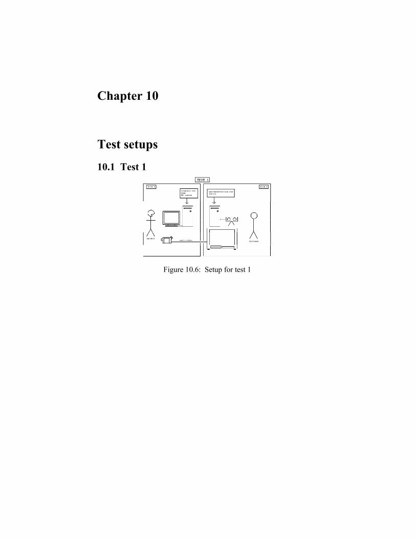
10.1 Test 1
Figure 10.6: Setup for test 1

10.2 Test 2
Figure 10.7: Setup for test 2

10.3 Test 3
Figure 10.8: Setup for test 3

10.4 Test 4
Figure 10.9: Setup for test 4


Chapter 11
How to run the rapport programs Above all one should check that the ELVISH_SESSION_HOST and ELVISH_SCOPE are set to the same values on all machines which are going to be used.
The current Rapport system uses 3 different programs, one to detect features in the audio, one to detect features in the video and one which maps the detected features to behavior. In fact there are 3 ways to run these programs: launching the executable itself (possibly with command line options), running the provided batch files or using the Rapport-launcher. Since the launcher uses the batch files and the batch files use the possible command line options, the batch files will be discussed first.
11.1 The batch files
11.1.1 Response Running the programs using the batch files: The %1,%2..,%n refer to the 1st,2nd,..,nth command line parameter. - Response using run-saso-rapport-response.bat : @if not defined ELVISH_SESSION_HOST set ELVISH_SESSION_HOST=%3 @if not defined ELVISH_SCOPE set ELVISH_SCOPE=%4 @echo ELVISH_SESSION_HOST = %ELVISH_SESSION_HOST% @echo ELVISH_SCOPE = %ELVISH_SCOPE% pushd ..\core\rapport\response\bin start response.exe -d -a %ELVISH_SESSION_HOST% -c ../conf/%1 -n world -o %2 @popd
Since the launcher will start the different programs on different machines and this is done by psexec (which sometimes has trouble

finding environment variables) the ELVISH_SESSION_HOST and SCOPE are to be used as arguments when launching this batch file, the batch file will use these if the variables are not found in the environment. After these two values are setup correctly, the batch file changes to the right directory and launches the Response program in a separate window (using start). As one can see this line uses a few command line parameters: -d, -a, -c, -n and -o. The -d switch is used to launch the Response program in debug mode so it will print more useful information on the standard output. The .a is used to specify the elvinhost which is to be used, -c the configuration file to use and -o the output file. The Response program has additional parameters which are not used in this batch file, these will be discussed later on when launching of the executable itself is discussed.
11.1.2 Audio - Audio using run-saso-rapport-audio.bat: @if not defined ELVISH_SESSION_HOST set ELVISH_SESSION_HOST=%1 @if not defined ELVISH_SCOPE set ELVISH_SCOPE=%2 @echo Using Elvinhost: %ELVISH_SESSION_HOST% @echo Using Elvinscope: %ELVISH_SCOPE% pushd ..\core\rapport\audio\bin start laun.exe @popd
For the exactly the same reason as the Response program this batch file uses command line parameters to set the ELVISH_SESSION_HOST and SCOPE when they are not found in the environment. Other then that this batch file just changes the directory and launches the executable, which doesn’t use any command line parameters.
11.1.3 GestureDetection - GestureDetection using run-saso-rapport-gesturedetection.bat @if not defined ELVISH_SESSION_HOST set ELVISH_SESSION_HOST=%1 @if not defined ELVISH_SCOPE set ELVISH_SCOPE=%2 pushd ..\core\rapport\gesturedetection\bin

@if %3 == 0 "C:\Program Files\Watson14\Sequences\SRI\Watson 1.4.lnk" @if %3 == 1 "C:\Program Files\Watson15\Sequences\SRI\Watson 1.5.lnk" start GestureDetection.exe -e %ELVISH_SESSION_HOST% %4 %5 %6 %7 %8 %9 @popd
This batch file uses the same mechanism like the batch file for the Audio and the Response program regarding the ELVISH_SESSION_HOST and SCOPE. The 3rd command line parameter should be either 1 or 0 indicating respectively indicating if version 1.5 (of the Watson program) should be used or not. Using this parameter the batch file decides which shortcut should be used, after that the GestureDetection program itself is started. Just like the -a switch for the Response program the GD program uses the -e switch to specify the elvinhost to be used. The rest of the command line parameters correspond to command line parameters of the executable itself and will be discussed later on.
11.2 Running the programs using the executables
11.2.1 Response The layout and the functionality of the configuration file used by this program can be found in chapter 3.2 of [LAM05]. Launching response -h gives us: response.exe [-c configfile] [-a adress] [-v] [-d] [-h] -n name name of the simulation, default is config file name -c file config file, default is "world.rsp" -a adress adress for elvin connection, default is environment variable ELVISH_SESSION_HOST -o file output all messages to this file -v verbose mode: output all Agents data -d debug mode: output all data -av avatar mode: non-reactive Agents are modeled -h displays help

You can edit or create your config file with "respedit.exe". To use Response, you also need to start a dimr session.
11.2.2 Audio This program uses no command line parameters, all settings are specified in the default configuration file default.cfg. Most of these values are self-explanatory and normally don’t need to be touched. The adress line in the configuration file is only used as the elvinhost when the variable ELVISH_SESSION_HOST isn’t found.
11.2.3 GestureDetection The layout and the functionality of the configuration file used by this program can be found in appendix 12. When the program is ran without any parameters all possible detection is disabled. Launching GestureDetection .h gives us: Possible command line options: -h | --help This output. -s | --slouch Use slouch detection. -r | --roll Use roll detection. -n | --nodsShakes Use detection of nods and shakes. -g | --gaze Use detection of gazeshifts. -m | --mimick Mimick the head motion, better not used with -n or -g. -e | --elvinserver <servername> Specify the elvinserver to use. (default: %ELVISH_SESSION_HOST%) -c | --config-file <configfile> Specify configfile to use. (default: test.cfg) -w | --numbers-of-worlds <numworlds> Specify the number of worlds to use.

-W | --worldname <worldname> Specify the name of first world to use. (default: world) -y | --yaw-pitch-roll Send out yaw,pitch and roll instead of Quaternions. -a | --agentname <agentname> Specify the agentname to use. (default: user)
11.3 Running the programs using the Rapport-launcher A first thing to note about the Rapport-launcher is that it was made last-minute and is based on the design of the SASO-launcher, therefore there is a lot of code which should be removed from this launcher, and there is also a lot of code which should be expanded to suit this launcher (i.e. the save and load functions). This chapter will explain the working of this launcher and the main functions which differ from the regular launcher and how these are used. At the time of the first version of this launcher the logger and replayer weren’t working optimal to be used properly with the Rapport programs, therefore, this first version shouldn’t be used for test 2 and 4, test 1 and 3 should work, but the log file produced by the logger won’t be in the right directory and may contain errors or might (for some reason) be unplayable for the replayer. However as soon as new versions of the logger and replayer become available, it’s not that much work to include the needed functionality into this launcher.
11.3.1 How it works As soon as the launcher is up and running (initialization and loading and saving is the same as the SASO-launcher), only the ‘Start Test’ and ‘Stop Test’ buttons should be used to start and stop different programs. The only case when the individual ‘Launch’ or ‘Kill’ buttons should be used is when a program might crash during a test and needs to be relaunched during this same test. Just below the ‘Start Test’ button there are two input boxes, one for the subject number and one for the number of the listener (only applicable for test 1). In the upper right hand corner there are 4 radio buttons which can be used to select which test is going to be done. Using this radio buttons all the necessary programs for the selected test will be select with the proper settings.
When the ‘Start Test’ button is used for the first time (with SBM and Unreal selected) it will run SBM and Unreal, deselect both

programs (they should be launched only once for a whole sequence of tests) and raise a warning. Since there will be a warning the first time, this means that the actual test won’t be started. After both SBM and Unreal are up and running ‘Start Test’ should be pressed again to launch the actual test. This will launch every single program needed for the particular test, but NOT start them. The reason that the current launcher doesn’t start the programs automatically is because the moment the program involves things which cannot be detected by the launcher (i.e. is the subject ready and sitting in the correct position? ). This means that the different programs must be set to start or record manually. An exception is when running the Response program, this program will start automatically and send out initial commands when this is done, for this reason the logger will most likely not log these commands. (this is not a feature, but a BUG and needs to be fixed in the next version).
After the test is completed the ‘Stop Test’ button should be used, this will make sure that the programs which need to be restarted (in case of another test) are closed, and that the logs (together with audio and video) are copied to the directory corresponding to the test. As mentioned above the log file of the logger won’t be copied to the right directory in the current version.
11.3.2 The code which makes this work Starting from line 1654 (after the line #---------------------OWN STUFF) there are a few start, stop and reset function which aren’t doing much more then sending out a proper Elvin message so the individual programs should do what they are asked to. The same goes for the reloadConfigFileGD function and the toggle functions after that. The toggle functions are used to toggle detection options of the GD program can be used before the program is started or when it is running. Besides the Elvin message which is send, the color of the corresponding buttons will change, indicating if an option is On (red) or off (yellow). The changeTestNumber function is called when the radiobutton mentioned earlier is changed, this function checks the programs which should be used for the specific test, sets the right options for the GD program and sets the machines, on which to run the different programs. The startTest function starts the programs checked (and needed) for the specific test. If SBM and/or Unreal are not started yet (still checked) it starts them, unchecks them and aborts the start function. The function also aborts if the test is already running (maintained by a boolean). If the function isn’t aborted for any of the reasons mentioned above a perl script is used to change the ParamWatsonUser.cfg file to use the right directory to record the image
sequence. A new directory specific for this test is created as well. After this the needed programs are started (if checked). The stopTest function kills the running programs (except for SBM and Unreal) and copies the logs (and the audio and video data) to the directory which has been created for this test.
The last function specific for this launcher are the openConfigFile functions, for the Audio and the GD program this just opens the used configuration file (on the specified computer! ) with notepad. For the Response program, respEdit is started and the path of the used configuration file (on the specified computer! ) is put into the paste buffer so it can easily be opened. Next to the code mentioned above there are a few initialization lines: set isRunning 0 set isRunningAudio 0 set dirname "" set rapportMachine1 Freud set rapportMachine2 Darwin set rapportMachine3 Folkman
Which are self explanatory but the last 3 values are the only way to change the 3 machines used by the launcher. Which machines is used for which program in which test is handled by the changeTestNumber function mentioned earlier.
Besides al this the function initGUI has been changed to display all the buttons needed for this launcher, the different (additional) GUI components and related functions are not in a tool array just like in the SASO-launcher, this is because the lack of time and lack of knowledge of tcl and the diversity between the different programs. The different launch and kill functions also contain a lot of .hard-coded. paths and references to certain programs or pieces of code.

Chapter 12
Configuration Parameters This appendix is meant to provide as an explanation for the configuration parameters for the GestureDetection program. The full list of feature which the GestureDetection program sends out:
[Sorry. Ignored \begin{small} ... \end{small}] Table 12.12: Complete list of features detected by the
GestureDetection program. (Under the current implementation the featurelist (see figure 12.12)
can be obtained by : grep %s GestureDetection.cpp | perl -pe "s/.*\"(%s.*)\".*/\$1/;") The %s is the agentName used and the %f corresponds to parameters which are send with the message.

At the moment the features mentioned above can be divided into 4 (+mimicking) categories, which can be detected and configured separatly:
1. Nods and Shakes 2. Gaze shifts 3. Slouches 4. Rolls 5. Mimicking Under most circumstances the default parameters as provided in this
document will suffice, however there can be situations where fine tuning is needed. The configuration file can be altered and reloaded once the program is running, so this will make it possible to test multiple settings in a short amount of time. Most of the time the system is used, the environment will be different from previous situations, so there is no perfect configuration. However these parameters can be used to fine tune the performance of the system.
12.1 The Parameters Threshold used to detect changes in the direction of the pitch, used to filter out noise and minor changes. This is used in the nod detection process. PitchThreshold = 0.001 Threshold used to detect changes in the direction of the yaw, it is used to filter out noise and minor changes. This is used in the nod detection process. YawThreshold = 0.001 Number of 'gazes' (no nod or shake, this is obtained from the Watson component) to detect before the counters are reset. gazeLimit = 15 Number of nods to detect (by the Watson component) before considering to report a headnod. (the PitchShiftCount is also used for this) nodLimit = 1

Number of shakes to detect (by the Watson component) before considering to report a headshake. (the YawShiftCount is also used for this) shakeLimit = 1 When the timer reaches this limit, there is a gaze shift. gazeShiftTimeLimit = 500 The minimum angle (in degrees) to discriminate between two gazes. gazeMinimumAngle = 5.0f The maximum angle (in degrees) which keeps a possible gaze shift alive. In fact the timer is reset when this angle exceeded while measuring a possible gaze. gazeNoiseAngle = 1.0f The displacement in mm from the central(stored position) along the x-axis. Used to detect slouches when the roll is less then slouchMaxRoll. slouchThreshold = 100.0f When the roll exceeds this angle (in radians) the slouchRollFactor is used to determine the slouch instead of the slouchThreshold. slouchMaxRoll = 0.3f Factor used to determine slouches when the slouchMaxRoll is exceeded. slouchRollFactor = 90.0f Factor used to set a different condition for slouching back and forth, so there is not one specific turning point. slouchUnSlouchFactor = 0.7f The minumum angle (in degrees) before a roll is detected. rollAngle = 15.0f

The following parameters are only used in mimicking mode and are used amplify the rotational values and to set boundaries for those values as well. mimickRotXAmpl = 2.0f mimickRotYAmpl = 2.0f mimickRotZAmpl = 0.65f mimickRotXMax = 0.3f mimickRotYMax = 0.45f mimickRotZMax = 0.25f
12.2 How the parameters are used
12.2.1 The Nods and Shakes detection This detection uses both the detection by the Watson and the raw data. The configuration parameters are used to combine both detection methods in the right way. In fact shakes and nods are quite similar except for the fact that the one is about rotation around the x-axis and the other about rotation around the y-axis, therefore we will only consider nods in this explanation. The GestureDetection program uses the Watson system with learned Hidden Markov Models (NODS_DETECTION_ALGO: HMM) for nod detection, for each frame it reports a 1 for a nod (or -1 for a shake) and a 0 otherwise. The reporting of nods uses two Watson configuration parameters: NOD_LOG_MIN_THRESHOLD and NOD_LOG_MAX_THRESHOLD. The second method uses the raw data obtained from Watson. The method counts the number of pitch shifts. A pitch shift is defined as a change in the direction of the pitch. This counter will keep increasing when there is no movement at all, since there will be small fluctuations around 0, because the data obtained from Watson isn’t perfect. To take away this unwanted effect the PitchThreshold is used to filter out these fluctuations. There are 3 parameters for combining both methods. The systems counts the amount of nods received from Watson, when this counter exceeds nodLimit-1 and the number of pitch shifts exceeds 1 a nod is reported and the number of pitch shifts is decreased by two. When the number of pitch shifts reaches 0 in this way, everything is reset. Next to nods all the ‘not nods/shakes’ are counted too and this counter is compared with the gazeLimit. When this counter is greater or equal to this limit everything will be reset too. In fact the combination of both methods is used for the detection and the ‘shift count’ method is used to count the nods, so the system doesn’t send out too much nods, this could happen when the Watson detection is used in a straight forward way.

12.2.2 Gaze shift detection The gaze shift detection can be configured through three different parameters. The gazeShiftTimeLimit is used to make sure a certain gaze is held long enough to report it as being a gaze shift; this will filter out stuff like nods and shakes and will prevent the system from sending out too much data. The gazeMinimumAngle is the minimum angular displacement (in either pitch, yaw or roll), between the current pose and the last recorded gaze, before the timer to report a gaze shift can be started. The gazeNoiseAngle is the maximum angular displacement, between the possible new gaze and the current rotation, which is allowed without the timer being reset.
12.2.3 Slouches The GestureDetection program is meant to be used with sitting subjects, although it may work just as good for standing subjects. When it comes to slouching there are three different positions: slouch right, normal and slouch left. A slouch to the side is reported when the subject moves his upper body to the side and/or when the head is tilted to this side. During initialization the normal position is stored, the detection of slouches uses this position and is configured with four additional parameters. The main parameter is: slouchThreshold, this is how far the head (due to upper body movement or tilting) should be displaced (along the x-axis) from the normal position before a slouch is reported. This threshold is only used when the roll (the tilting) of the head is smaller then the slouchMaxRoll. If the roll exceeds the slouchMaxRoll then the slouchRollFactor is also used. Since the x-coordinate of the head also changes when the head is tilted the slouchRollFactor can be used to detect slouches when the head is tilted more then slouchMaxRoll. The slouchRollFactor multiplied by the absolute roll (in radians) is added to the threshold to calculate the new threshold for this case. To avoid switching between slouch and normal (and back) repeatedly when the subject is on the edge of slouching (or not) the slouchUnSlouchFactor is used. This factor multiplied with the slouchThreshold is used as a range around the stored position within which a ‘unSlouch’ (switching back to normal) is reported.
12.2.4 Rolls The roll detection only uses the rotation along the z axis; a roll to either the right or left is reported when this rotation exceeds the rollAngle. Since rolls are expected to hold shorter then slouches and are more frequent to change no unRoll construction was used here.

12.2.5 Mimicking The mimicking rotates the head (skullbase) using the rotational data received from Watson. Since the tracker doesn’t always work 100% accurate and tends to be more conservative as opposed to what is really happening, the mimickRot[X—Y—Z]Ampl can be used to amplify the rotation. To filter out unrealistic values the mimickRot[X—Y—Z]Max can be used. All these rotations are radian angles. The current slouch implementation rotates three spine bones; the angle of the lowest spine bone is computed in the way described below. The angle shown below shows the (estimated) height (default: 300 mm) from the lowest spine bone to the skullbase. The distance v.x shown in the figure is the horizontal displacement from the starting position. Using trigonometry the shown angle is computed and used to construct a quaternion to rotate the lowest spine bone. The other two spine bones are rotated in the opposite direction with 50% of the angle to compensate the rotation and make the slouch look more realistic. If v.x exceeds the maximum value (default: 250 mm) it is set to this value to avoid unrealistic slouches.

Chapter 13
Watson This appendix should aid in how to get Watson up and running and tune the performance.
13.1 Getting the software installed To install the Watson program the normal installer can be used, after the SRI software has been installed, since the current version(s) of the Watson program doesn’t work with the current IEEE 1394 WinXP SP2 driver, therefore these instructions (http://www.videredesign.com/xp2_workaround.htm ) must be followed to reinstall the SP1 driver. After that the supplied configuration files (ParamUser.cfg and calib-own.ini ) must be copied to: C:\Program Files\Watsonxx\Seqeunces\SRI (where xx is the version number i.e. 15). To use Watson from the launcher a shortcut has to be made from this same directory named: Watson x.x.lnk (where x.x is the version number, i.e. 1.5) and it has to point to the watsonxx.exe executable in the C:\Program Files\Watsonxx\bin directory, the start directory has to be: C:\Program Files\Watsonxx\Seqeunces\SRI.
13.2 Performance Once everything is up and running it could be that the performance of the tracker isn’t optimal. This can have all kinds of reasons; there are a few relative quick and easy ways to tweak this performance.
In general much background light is not a good thing, the background light and the ambient light should light the whole shot but too bright is not good. If the face isn’t bright enough a spot light can be used to brighten only the face itself. If the overall image remains too bright, the calibration file can be altered, by lowering the gain value (default : 100 ), doing this will likely bring up the need for a spotlight to brighten the face itself.
The best distance from camera to the user is a little over 3 feet. Ideally the camera should be placed at the same height as the user’s eyes. Since there is a screen at this position, most tests were done with

placing the camera a little lower and facing up. To initialize the tracker properly, it.s best that the user is looking directly into the camera when the tracker is started.
13.3 Configuration An example ParamUser.cfg is shown below. The meaning of the different parameters are explained2 in the ParamWatson.cfg file. [SECTION_WATSON] COMPUTE_SIMPLE_POSE: FALSE AUTO_REINIT: TRUE [SECTION_SIMPLE_TRACKER] DETECTION_TASKS: DEPTH_FILTER DETECT_FACE DETECT_MULTI_FACE END STATE_TASKS: ALWAYS ON_INIT ON_REINIT END [SECTION_NETWORK] CONNECT_SOCKET: TRUE NAME_HOST: 127.0.0.1 TYPE_INFO_SENT: INFO_TIMESTAMPS INFO_POSES INFO_PREVIOUS_LINKS_ONLY INFO_HEAD_NODS END ENABLE_REMOTE_COMMANDS: TRUE [SECTION_RECORDER] IMAGE_PREFIX_FILENAME: C:\saso\saso\core\rapport\testdata\ 12_21_2005_11h42m32s_Subject1-Test3-Listener1\imageseq\Image- OUTPUT_PARAMETER_FILENAME: C:\saso\saso\core\rapport\testdata\ 12_21_2005_11h42m32s_Subject1-Test3-Listener1\imageseq\ParamSeq.cfg
13.4 Current issues Most of the time the tracker doesn’t follow the head all the way to the right or left (when rotating), if the light and calibration is setup poorly this can even lead to tracking no rotation along the y axis at all. The same problem arises with the rotation around the x axis, sometimes this rotation is not detected properly by the tracker and when doing head 2feel free to contact me for more details about the configuration, I also have more information I received from Louis-Philippe Morency, which isn’t shown here

nods the tracker seems to move up and down instead of rotating along the x axis.

Chapter 14
Annotating data Because of the lack of time, priority and the number of testdata not much time was spend in annotating data. However a number of tools were used during the internship. These tools are discussed in section 14.2. The actual data which is subject to be annotated is covered in section 14.3, suggestions for future work will be given in the last section of this appendix. The next section will cover the reason for annotating data.
14.1 Why annotate data? There are several reasons why annotating data could be useful within the Rapport project. First of all, if data is annotated and stored, it can easily be reused in the future. This data can then be reused with the same system with a different configuration, to compare the results and see which configuration works better. It is also possible to annotate more features than available to detect with the current system. In this way, when new feature detection is available, it can be tested at once (assuming it can load the previously recorded data). If the process of testing and comparing results with annotated data can be automated, machine learning can be used to improve the performance of the different detection programs. Even with a system under development, annotated data could be useful (as long as it can be used as input). For instance annotated data could have been useful during the development of both the GestureDetection and Audio component, because this takes away the need to shake, slouch and shout all day just to test the system. With new components being added in the future, annotation can be even more useful even if it’s just to demonstrate the functionality of the system. With multiple components it’s likely to have multiple audio and video sources, however for annotation and demonstration purposes and for reusability it might be useful to combine all these source into one video.
Even outside of the Rapport project it could be useful to share annotated data with other research groups, because good annotated data is not widely available.

14.2 Possible tools This section will cover the three different annotation tools used during this internship. It will briefly show what each tool can and cannot do. Since all three the programs have a lot of features3 this chapter will not give a full list of features. This chapter is meant to give an idea of the three programs which were used. It should also aid in the choice4 which has to be made when serious annotation is going to be done for the Rapport project.
14.2.1 Transcriber This annotation tool is used by the current version of the Audio program, as mentioned in part 3, chapter 4.4.2 of [LAM05]. Morales [LAM05] already mentions that this program has many features which aren’t used right now but could be useful in the feature. The software has been tested on several Unix system and on Windows XP/Windows 2000, the program can be found at: http://trans.sourceforge.net/ .
14.2.2 ELAN ELAN is a multimedia annotation tool developed at Max Planck Institute for Psycholinguistics in Nijmegen, the Netherlands. Unlike Transcriber, this tool works with audio and video files. It can even open multiple files. ELAN uses JRE and therefore is available for Windows, Mac OS X and Linux. After a bit of clicking and exploring or just by reading the quickstart guide or consulting the manual it’s quite easy to use. Although it’s quite easy to get started using ELAN, it does have a lot of functionality which can be useful for annotation. The software, including the manual and some examples can be found at: http://www.mpi.nl/tools/elan.html .
14.2.3 Anvil Anvil is a annotation tool, by Micheal Kipp and is also used at USC. Just like ELAN, Anvil can be used to annotate video data. Anvil didn’t seem to work with a number of video files or wave files we used. The possibility to use several files at once isn’t possible either. Other than that Anvil has loads of possibilities, for this reason it takes a bit more time to get up and running with Anvil compared to ELAN. A very useful feature of Anvil is that you can create your own specification file which allows you to completely customize how your annotation scheme looks like. Since Anvil is also used at USC we received their 3most of them unknown to me 4which annotation tool to use?

specification file5 (from Serdar Yildirim) which can be used for annotations for the Rapport project as well. The fact that the same program is used at USC would be a good reason to use Anvil for the Rapport project as well, since the program has a lot of features and comes with a good documentation. Using the same program with the same specification file (or almost the same) would ease the exchange of annotated data. The program only works on windows systems and can be found at: http://www.dfki.de/k% ipp/anvil/ .
14.3 The data The current Rapport system has 3 different outputs which can be used for annotation (see table 14.13). Morales already mentions the use of annotation tools for his Audio program in part 3, chapter 4.4.2 of [LAM05]. The trs file generated by the Audio program can be compared to a hand annotated file and the results of this comparison can be used to improve the performance of the Audio program. The same can be done with the GestureDetection program, which at this point only generates a simple text file containing timestamps together with the detected feature. Because annotating wasn’t the highest priority and because no definite choice was made which annotation program to use, the output was kept simple. However once a choice has been made which annotation tool to use this simple text file can easily be converted to an xml file compatible with this tool. This way a movie, constructed from an image sequence of the Stereo Camera (see appendix 15.3), can be annotated by the GestureDetection program and compared to hand annotated data. The output from the DV camera, which contains both audio and video can easily be annotated. However, none of the components of the system can use this data as input. Log files of both the Audio and the GestureDetection program will not be of any use when a comparison is going to be made with the data from the DV camera, since the timing is different. If the video of Unreal is recorded (with a screen capture program) the same problem will arise; the fact that there is no timing or synchronization between this video and the other sources.
• Output from the DV camera (Audio + Video) • Output from the stereo camera (Video) • Output from the microphone (Audio) • Unreal (Video)
Table 14.13: Output data of the Rapport system, which can be annotated.
5I still have a copy of this file, on request this file can be send

14.4 Future work Annotating is already possible and definitely useful within the Rapport project, but there is still a lot of work to be done before all potential can be utilized. Table 14.14 shows suggestions for future work on the topic of annotating within the Rapport project.
• Choose one Annotation tool (or maybe a separate one for audio). • Collect more data and annotate it. • Use data as input for both the Audio and the GestureDetection
program, and store the results.
• Convert the results of the GestureDetection (and/or Audio) to a format readable by the used annotation tool.
• Use machine learning to tune the performance of the systems. • If all the data sources need to be combined into one video,
a synchronization solution has to be found. Table 14.14: Future work regarding annotation.
Most of the suggestions given in table 14.14 are already possible with minor alterations or additions. Serious problems may arise when trying to combine the different sources. This has already been tried and done for one demonstration movie, using Final Cut Pro. For demonstrational purposes this might proof to be good enough but since all synchronization and timing has to be aligned and corrected by hand this task is subject for human error. At this point there is no proper way of synchronizing and timing all the different sources, if a proper solution for this can be found putting together the different sources would be quite easy.

Chapter 15
Additional work This appendix will cover additional work which is outside of the scope of this report. All the files mentioned in this appendix can be found in the data or scripts directory of the Rapport system.
15.1 Smartbody Through personal interest in the Smartbody system, the currently available animations were discovered. However, these animation couldn’t be used in the way that was needed. The default behavior of Smartbody was to animate back to the default pose after an animation was finished. An important group of animations, which were available in DIMR and not in Smartbody, are the slouches. The process how the (non-existing) slouch animations were made will briefly be covered in section 15.1.2. The workaround to actually put these animations to use will be covered first, in the next section.
15.1.1 SKM / SKP, the workaround Several types of files can be used by Smartbody to lead to an actual animation. Table 15.15 shows these file types. File Extension Meaning/Usage .SKM File describing a certain animation
(using key frames) .SKP File describing a pose .XML Beavin XML files used to set a
default pose .SEQ Sequence files to load a sequence
of Smartbody animations .ME Mapping from poses and motions
to controller which can be used by SBM
Table 15.15: The different file types used in the workaround.
The animations which were found were .SKM files, where the M stands for motion. Smartbody also uses .SKP files where the P stands
for pose. Both of these (like all other types mentioned in table 15.15) are plain text. Leaving out the details, both .SKP and .SKM files list all bones used and after that list the quaternions (only x,y,z) describing the bone rotations. The difference between both files lies in the fact that .SKM files use multiple lines with a timestamp to support multiple frames where .SKP files only describe one set of bone rotations, hence the name .SKP(ose). As mentioned above the Smartbody system animates back to the default pose after an animation has been played. To support slouches in SBM there were two options: disable the animation to the default pose or set a new default pose. Since the first option wasn’t possible the second one has been used. This was in fact quite useful, since there also were some poses which weren’t included in any animations but could be useful for the Rapport system.
To actually utilize the changing of the default pose, more .SKP files were needed. Since both .SKP and .SKM files were plain text some perl scripts were made to convert the first or the last frame of a .SKM file to a .SKP file. Some other scripts were made to aid in the construction of the corresponding .XML and .SEQ files and add the proper lines to a .ME file. In the end to play an actual animation, SBM was used to load a sequence file6 which points to several BML (Beavin XML) files to set a new default pose. Since SBM automatically animates between poses this was a fair enough work around to use Smartbody with slouches and a few other animations.
15.1.2 Maya The .SKM and .SKP files mentioned in the previous section were converted from Maya. During the internship there wasn’t much active Maya development for the doctor (the agent in the SASO system), therefore new animations had to be made by myself. Fortunately Aaron Hill had quite some Maya experience and he provided me with a Maya model of the doctor. He also assisted in the animation and exporting process. Finally it was possible to make a few simple (mainly slouches) animations which could be exported to an .SKM file for further usage.
15.2 Making movies out of image sequences To make it possible to use the data from the stereo camera for annotation (see appendix 14), a few perl scripts were made (see table 15.16). The first attempt to create a movie from an image sequence was done by creating a Camtasia project file and loading this file into Camtasia. This approach was working, although Camtasia isn’t suitable to load project files which contain a lot of images within a small time 6Using a sequence file multiple times made the system crash at first, thanks to Andrew Marshall this problem was resolved

span. For this reason it took hours to load and to process the sequence into a final movie.
The second approach uses a perl script to create a new image sequence (with fixed frame rate) from an existing one. If the existing sequence has been recorded with Watson 1.5 (with timestamps enabled), a timestamps.txt file will be present. If no timestamp file is present one can be obtained by using another script to create such a file using the timestamps from the filesystem. The final sequence then can be loaded by a movie processing program (i.e.: TMPGenc http://www.tmpgenc.net/ ) to load a sequence with fixed frame rate and produce a movie. File Meaning/Usage imageseqToConstantFrameRateSeq.pl
Uses a image sequence
and timestamp to create a new sequence with constant fps createTimestamps.pl Creates a timestamp.txt file for a given imagesequence using timestamps from the filesystem imageseqToXML.pl (DEPRECATED), Constructs a valid Camtasia project file from an image sequence
Table 15.16: Scripts to produce a movie from a (Watson) image
sequence.
15.3 Putting together different movies To make a short demonstration movie, some time has been spent trying to combine the different audio and video sources. Final Cut Pro has been used for this purpose with help of Scott Rocher. The demonstration movie which has been made, uses data from subject 4 doing test 3 (see chapter 7). This movie combines the stereo camera output, the DV camera output and a screen capture of Unreal. The same has been done for an informal test 3. With some time and effort the demonstration movies were produced. Although sOme video sources had to be cropped, sped up and others had to be slown down. Producing such a movie is quite a laborious task and with the current data it’s nearly impossible to get a (close to) perfect result. If the final movie only serves as demonstration this could be good enough but otherwise

some sort of timing between the different sources is needed during the recording.

Chapter 16
Posio These are the installation notes I received from Ronald Poppe. I also had some mailings with Ronald about certain issues I ran into, upon request this information is available as well. POSIO installation: 1. Install DirectX 9.0: - extract dx90bsdk.exe - check to install samples and code - check debug version 2. Install IPL 2.5 - extract ipl25.exe 3. Install OpenCV 3.1: - extract OpenCV_b3.1.exe - have OpenCV add itself to your path 4. Build streams.h: - This is described in <OpenCV Root>\docs\faq.htm under "When I try to build one of the apps, I get an error, streams.h not found." 5. Patch syncfilter: - from streocam.zip overwrite Syncfilter.h and Syncfilter.cpp in <OpenCV Root>\filters\SyncFilter - from streocam.zip overwrite cvcam.cpp in <OpenCV Root>\otherlibs\cvcam\src\windows - from streocam.zip overwrite cvcam.h in <OpenCV Root>\otherlibs\cvcam\include - open Syncfilter.dsp and build Syncfilter.ax in Release mode - execute <OpenCV Root>\bin\regsvr32 Syncfilter.ax to register filter

6. Patch CVcam: - from cvcam_combi.zip overwrite everything except cvcam.h in <OpenCV Root>\otherlibs\cvcam\src\windows - from cvcam_combi.zip overwrite cvcam.h in <OpenCV Root>\otherlibs\cvcam\include - open <OpenCV Root>\otherlibs\cvcam\make_win\cvcam.dsp and build in both Release and Debug mode 7. Build CVAux: - open <OpenCV Root>\cvaux\make\cvaux.dsp and build in Release and Debug mode 8. Extract and compile Posio: - unzip posio.zip - open posio.dsw en check if under Tools->Options->Directories <OpenCV Root>\otherlibs\cvcam\include and <OpenCV Root>\bin are listed under include files - check if Build-> Set Active Configuration "Main - Debug" or "Main - Release" is selected - build all and run If something goes wrong, check the dependencies under Project->Dependencies. Main depends on CV, CVcam and HighGUI. CVcam depends on CV and HighGUI. HighGUI depends on CV. Keep in mind that the program accepts only images of size 320x240 with a color depth of 24 bits. AVI's of a limited number of codecs can be played and not every JPEG compression is supported.
