cr250 engine service manual
TRANSCRIPT
v'
SERVICE INFORMATION
FOR.
FIARLEY-DAVIDSON SPRINT MODEL IIRTI
Printed in U. S. A"oRIG. 2-6r
HARLEY.DAVIDSON MOT'OR CO.Milwaukee 1, Wisconsin, U. S. A.
7',
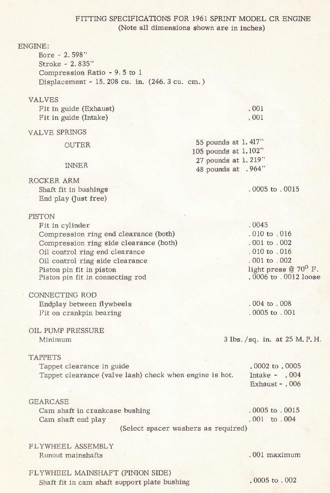
FITTING SPECIFICATIONS FOR 1961 SPRINT MODEL CR ENGINE(Note all dimeneions shown are in inches)
ENGINE:Bore - 2.598"Stroke - 2.835"Compression Ratio - 9. 5 to IDisplacement - 15.208 cu. in. (246.3 cu. cm.)
VAI-VESFit in guide (Exhaust) .001
. 00rFit in guide (Intake)
VALVE SPRINGS
OUTER 55 Pounds at L' 4I7"105 Pounds at 1' 102"
INNER 27 Pounds at L' 219"48 pounds at ,964"
ROCKER ARMShaft fit in bushings .0005 to .0015End play (Just free)
PISTONFit in cylinder .0045Compression ring end clearance (both) .010 to .016Compression ring side clearance (both) .001 to .002Oil control ring end clearance .010 to .016Oil control ring side clearance .001 to .002Piston pin fit in piston light press @ 70o F.Piston pin fit in connecting rod .0006 to .0012 loose
CONNECTING RODEndplay between flywheels .004 to .008Fit on crankpin bearing .0005 to .001
OIL PUMP PRESSUREMinimum 3 lbs. /sq. in. at 25 M. P. H.
TAPPETSTappet clearance in guide 0002 to .0005Tappet clearance (valve lash) check when engine is hot. Intake - .004
Exhaust - .006
GEARCASECam shaft in crankcase bushing .0005 to .0015Cam shaft end play .001 to .004
(Select spacer washers as required)
FLYWHEEL ASSEMBLYRunout mainshafts .00f maximum
FLYWHEEL MAINSHAFT (PINION SIDE)Shaft fit in cam shaft support plate bushing .0005 to .002
t
I
l
2
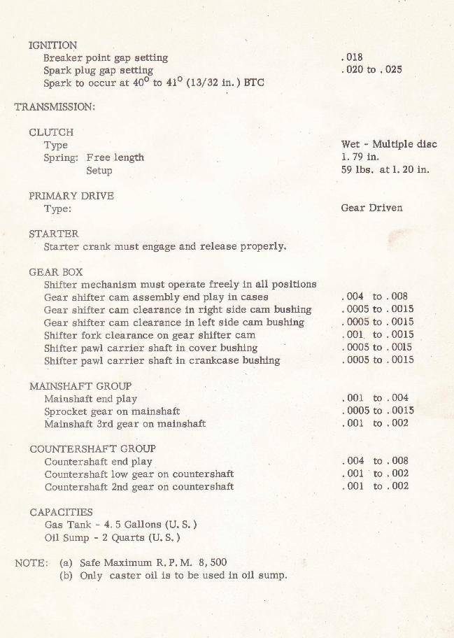
IGNITIONBreaker point gap settingSpark plug gap settingSpark to occur at 40o to 4lo (13/32 rn. ) BTC
TRANSMISSION:
CLUTCHTlpeSpring: Free length
SetuP
PRIMARY DRIVETYPe:
STARTERStarter crank must engage and release properly.
GEAR BOXShifter mechanism must operate freely ln all positlonsGear shifter cam assembly end play in casesGear shifter cam clearance in rlght side cam bushlngGear shifter cam clearance in left slde cam bushlngShifter fork clearance on gear shifter camShifter pawl carrier shaft in cover bushingShifter pawl carrler shaft ln crankcase bushing
MAINSHAFT GROUPMainshaft end playSprocket $ear on mainshaftMainshaft 3rd gear on mainshaft
COUNTERSHAFT GROUPCountershaft end playCountershaft low gear on countershaftCountershaft 2nd gear on countershaft
CAPACITIESGas Tank - 4.5 Gallons (U. S. )Oil Sump - 2 Quarts (U.S.)
NOTE: (a) Safe Maxlmum R. P. M. 8, 500(b) Only caster oil is to be used in oil sump.
.0r8
.020 to .025
Wet - Multtple disc1. 79 tn.59 lbs. at 1.20 ln.
Gear Drlven
.004 to .008
.0005 to .0015
.0005 to .0015
.001 to .0015,0005 to .0015.0005 to .0015
.001 to .004
.0005 to .0015
.001 to .002
.004 to .008
.001 to .002
. 00f to .002
.3
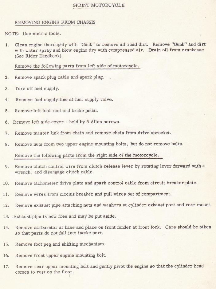
SPRINT MOTORCYCLE
REMOVING ENGINE FROM CHASSIS
NOTE: Use metric tools.
1. Clean engine thoroughly with "Gunk" to remove all road dlrt. Remove "Gunk" and dirtwith water spray and blow engine dry with compressed air. Draln oll from crankcase(See Rlder Handbook)
Remove the following parts from left slde of motorcycle.
2. Remove spark plug cable and spark plug.
3. Turn off fuel suppiy.
4, Remove fuel supply line at fuel supply valve.
5. Remove left foot rest and brake pedal.
6. Remove left side cover - held by 5 Allen screws.
7. Remove master link from chain and remove chain from drlve sprocket.
8. Remove nuts from two Llpper engine mounting bolts, but do not remove bolts.
Remove the following parts from the right side of the motorcycle.
9. Remove clutch control wire from clutch release lever by rotatlrtg lever forward wlth awrench, and disengage clutch cable.
10. Remove tdchometer drlve plate and spark control cable from circuit breaker plate.
11. Remove wlres from circuit breaker and pull wires out of compaftment.
L2, Remove exhaust pipe attaching nuts and washers at cylinder exhaust port and rear mount.
13. Exhaust pipe is now free and may be put aside. .
L4. Remove carburetor at base and place on front fender at front fork. Care should be takenso that parts do not fall into intake port.
f 5. Remove foot peg and shifting mechanism.
L6. Remove front upper engine mounting bolt.
L7. Remove rear upper mounting bolt and gentl.y pivot the engine so that the cylinder headcomeg to rest on the floor.
18. Whtle slppordng the englne from below, remove the lower mountlng bolt, Care muetbe teken ln removlng the last mountlng bolt so that the englne does not drop.
INSTALLING ENGINE IN CFI,ASSIS
hto the freme aimply reverse order of dlsassemblynotlng the followlng.
Clrcult breaker:Both black wlres are connected to clrcult breaker wire gtudgcrew.
Rear Chaln:
Replace rear chaln on englne sprocket before left elde coverls tnstalled.
OII.:Fill otl sump wtth 2 Quarto (U. S. ) of caster oll.
SPRINT ENGINE DISASSBMBLY
CYI.INDER HEAD
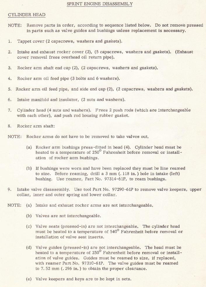
NOTE: Remove parts in order, according to sequence listed below, Do not remove pressedin parts such as valve, guides and bushings unless replacement is necessary.
1. Tappet cover (2 capscrews, washers and gaskets).
2. Intake and exhaust rocker cover (2), (5 capscrews, washers and gaskets). (Exhaustcover removal frees overhead oil return pipe).
3. R.ocker arm shaft end cap (2), (2 capscrews, washers and gaskets).
4. Rocker arrn oil teed pipe (3 bolts and 6 washers).
5. Rocker arm oil feed pipe, and side end cap (2), (2 capscrews, washers and gaskets).
6. Intake manifold and insulator, (2 nuts and washers).
7. Cylinder head (4 nuts andwashers). Frees 2 push rods (which are interchangeablewith each other), and push rod housing rubber gasket.
8. Rocker arm shaft:
NOTE: Rocker arms do not have to be removed to take valves out.
(a) Rocker arm bushings press-fi{ed in head (4). Cylinder head must beheated to a temperature of 250" Fahrenheit before removal or install-ation of rocker arrn bushings.
(b) If bushings were worn and have been replaced they must be line reamedto size. Before reaming, drill a 3 mm (. 118 in. ) hole in intake (left)bushing. Use reamer, Part No. 97314-61P, to ream bushings.
9. Intake valve disassembly" Use tool Part No. 97290-6LP to remove valve keepers, uppercollar, inner and outer spring and lower collar.
u NOTE: (a) Intake and exhaust rocker arrns are not interchangeable.
(b) Valves are not interchangeable.
(c) Valve seats (pressed-in) are not interchangeable. The cylinder headmust be heated to a temperature of 5400 Fahrenheit before removal orinstallation of valve seat inserts.
(d) Va1ve guides (pressed-in) are not interchangeable. The head must beheated to a temperature of 250u Fahrenheit before removal or install-ation of valve guides. Guides must be reamed to si.ze, if replaced,with reamer Part No. 97310-6lP. The valve guides must be reamedto 7.52 mm (. 296 in, ) to obtain the proper clearance"
(e) Vatrve keepers and keys are to be kept in sets.
o
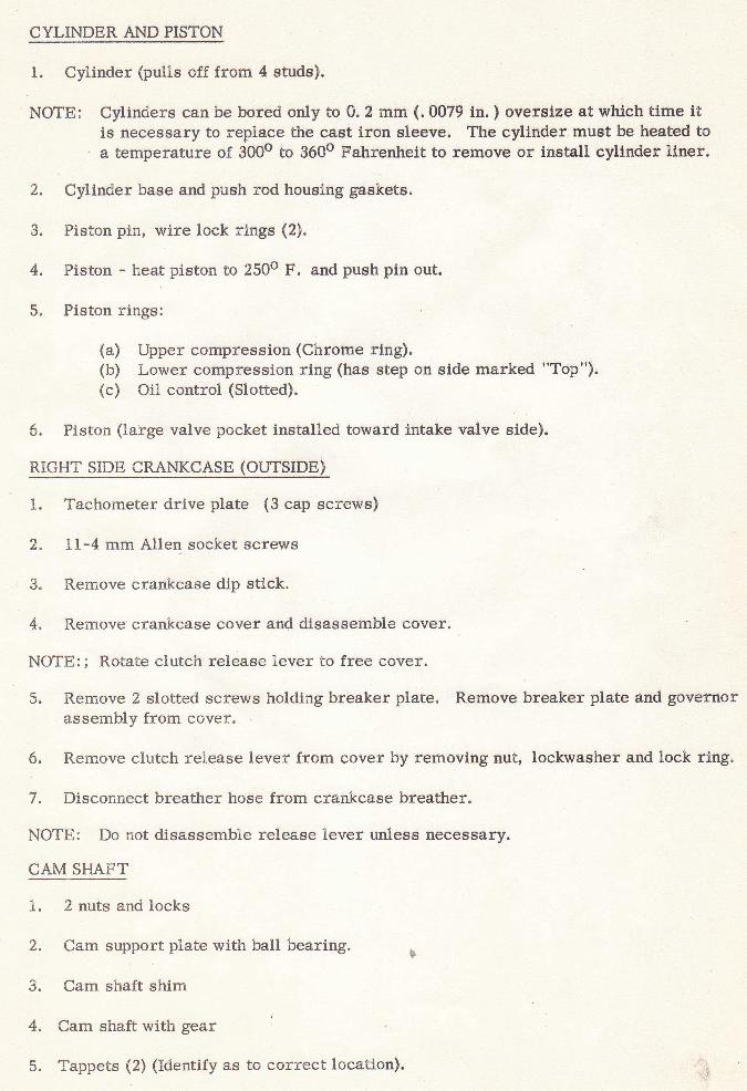
CYLINDER AND PISTON
1. Cylinder (pulls off frorn 4 studs).
NOTE: Cylinders can be bored only to 0.2 mm (.0079 ln. ) oversize at which time iti.s necessary to replace the cast iron sleeve. The cyllndef must be heated toa temperatr.lre of 3000 to 3600 Fahrenhelt to rernove or install cylinder liner.
2. Cylinder base and push rod housing gaskets.
3. Piston pin, wire lock rings (2).
4, Fiston - heat piston to 2500 F. and push pin out.
5. Piston rings:
(a) Upper compression (Chrome ring).(b) Lower compression ring (has step on side rnarked "Top").(c) Oitr control (Slotted),
6. Fiston (large valve pocket lnstalled toward intake valve side).
RIGI{T SrpE CRANKCASE (OUTSTpB)
1. Tachometer drive plate (3 cap screws)
2. L1-4 mm Allen socket screws
3" Remove crankcase dip sti.ck.
4. Remove crankcase cover and disassemble cover.
NOTE:; Rotate clutch reLease lever to free cover.
5. R.emove 2 slotted screw's holding breaker plate. Remove breaker plate ahd govefnorassembly from cover.
6, Rernove clutch release lever from cover by removing nut, lockwasher and lock rlng"
7. Disconnect breather hose from crankcase breather.
NOTE: Do not disassemble release leven unless necessary.
CAM SHAFT
1. 2 nuts and locks
2. Cam support plate with bali bearing. E
3. Cam shaft shim
/*. Carn shaft with gear
5. Tappets (2) (Identify as to correct location).
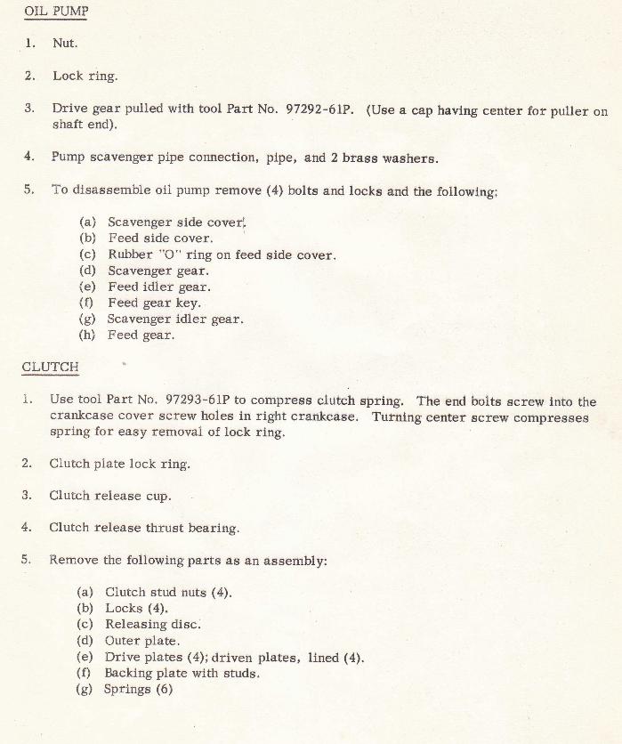
OIL PUMP
1. Nut.
3. Drive gear pulled with tool Part Na. 97292-61P. (Use a cap havlng ceuter for puller onshaft end).
4. Pump ec0venger pipe connection, pipe, and 2 brass washers.
5. To disaesemble oll purnp remove (4) bolts and locka and the followlng;
(a) Scavenger side coverl(b) Feed side cover.(c) Rubber "O" ring on Jeed side eover.(d) Scavenger geaf.(e) Feed idler gear.(f) Feed gear key.(g) Scavenger idler gear.(h) Feed gear.
CLUTCH
1. Use tool Part No. g72g3'6IP to cotnprese clutch sprlng. The errd bolte Bcrenr lnto thecrankcase cover screw holes tn right crdnkcase. Turning center screw compressesspring for easy femoval of lock ring.
2. Clutch plate lock ring.
3. Clutch release cup.
4, Clutch releage thrust bearing.
5. Remove the following parts as an assembly:
(a) clutch stud nuts (4).(b) Locks (4).(c) Releasing disc.(d) Outer plate.(e) Drive plates (4); drtven platesn ltned (4).(f) Backing plate with studs.(g) Springs (6)
a
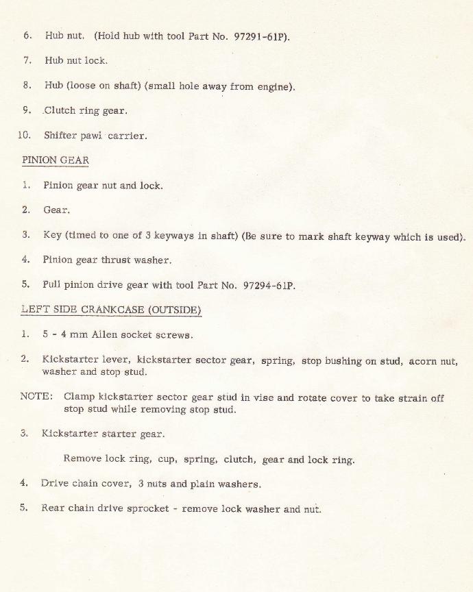
6. Ht& nut. (Hold hub with tool Part No. 97291-61P).
7, Hub nut lock.
8, Hub (loose on shaft) (small hole away from englne).
9, ,Clutch rlng gear.
10. Shlfter pawl carrler.
Pil.{ION GEAR
1. Finlon gear nut and lock.
2. Gear.
3. Key (timed to one of 3 keywayc lrr shaft) (Be sure to rnark shaft keyivay whtch le used).
4. Plnlon gear thruet waeher.
5. Pull plnion drive gear with tool Part No. 97294-61p.
LEFT SrpE CRANKCASE (OUTSIDE)
1. 5 - 4 mrn Altren eocket acrewg.
2. Kickstarter levef, klckstarter eector geaf, eprlng, etop bushlng on gtud, acorn nut,washer and stop stud.
NOTE: Clamp kickstarter sectof gear stird lrr viee and rotate cover to take straln offstop stud while tremoving stop etud.
3. Klckstarter startef gear.
Remove lock ring, cupr spring, clutch, geaf end lock ring.
e 4. Drive chain cover, 3 nuts end plairr washers.
- 5. Rear chain drive sprocket - remove lock washer and nut.
9
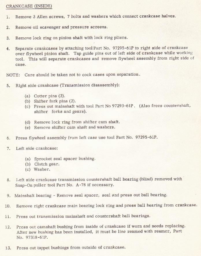
l. Remove 3 Allen screws, 7 bolts and washers which connect crankcase halves.
2. Remove oil scavenger g.nd pressufe screens'
3. Remove lock rlng on pinlon shaft with lock ring pliers.
4. Separate crankcaees by attaching tool Part No. 97295-6IP to right side of crankcaseover flywheel pinlon shaft. Tap guide pins out of left side of crankcase while workingtool. This will separate crankcases and remove flywheel assembly from right side ofca8e.
NOTE: Care should be taken not to cock cases upon separation.
5. Right side crankcase (Transmission disassembly):
(a) Cotter pins (2).(b) Shifter fork pins (2).(c) Press out mainshaft with tool Part No 97293-61P. (Atso frees countershaft,
shifter forks and gears).
(d) Remove lock ring from shifter cam shaft.(e) Remove shifter cam shaft and washers'
Press flywheel assembly from left case use tool Part No. 97295-6LP.
Left side crankcase:
(a) Sprocket seal spacer bushing.(b) Clutch gear.(c) Washer.
Left side crankcase transmission countershaft ball bearing (blind) removed withSnap-On puller tool Part No. A-78 if necessary.
9. Mainshaft bearing - Remove seal spacer, seal and press out ball bearing.
10. Rernove right crankcase main bearing lock ring and press ball bearing from crankcase.
11. Press out transmission mainshaft and countershaft ball bearings.
LZ. Press out camshaft bushing from inside of crankcase if worn and needs replacing.After new bushing has been installed, it must be line reamed with reamer, PartNo. 97318-6rP.
6.
7.
8.
13. Press out tappet bushings from outside of crankcase.
10
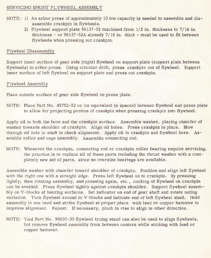
qpRvrclNg SPRTNT FLYWHEEL ASSEMBLY
NOTE: f) An arbor press of approximately 10 ton capacity ls needed to assemble and dis-assemble crankpin in flywheels.
2, Flywheel support plate 96137-52 machined from I/2 in. thickness to 7/L6 in.thickness - or 96L37-52A alreadV 7/ 16 ln. thlck - must be used to fit befweenflywheels when pressing out crankpin.
Flryheel Disasselnblv
Support inner surface of gear side (right) flywheel on support plate (support plate betweenflywheels) 1n arbor.press. Using circular drift, press crankpin out of flywheel. Supportinner surface of left flywheel on support plate and press out crankpin.
Flywheel Assembly
Place outslde surface of gear side flywheel on press plate.
NOTE: Piace Part No. 45752-52 or its equivalent (a spacer) between flywheel and press plateto ailow for projecting portion of crankpin when pressing crankpin into flywheei.
Apply oil to both the bore and the crankpin surface. Assemble washer, placing chamfer ofwasher towards shoulder of crankpin. Align oil holes. Press crankpin in place. Blowthrough oil hole in shaft to check alignment. Apply oil to crankpin and flywheel bore. As-semble roller and cage assembly. Assernble connecting rod.
NOTE: Whenever the crankpin, connecting rod or crankpln roller bearing require servicing,the practice is to replace all of these parts including the thrust washer with a com'-pletely new set of parts, since no overslze bearings are available.
Assemble washer with chamfer toward shoulder of crankpin. Positlon and align left flprvheelwith the right one with a straight edge. Press left flywheel on to crankpin. By pressinglightly, then rotating assembly, and pressing again, etc. , cocking of flywheel on crankpincan be avoided. Press flyruheel tightly against crankpin shoulder. Support flyvrtheel assem-bly on V-blocks at bearing surfaces. Set indicator on end of gear shaft and rotate notingvariation. Turn flywheel around in V-blocks and indicate end of left flywheel shaft. Holdassembly in one hand and strike flywheel at proper.place with lead or copper hammer totrmprove alignment. Repeat. If necessary, pinch in vise to align in other direction.
NOTE: Tool Part No. 96650-30 flywheel truing stand can also be used to align flywheels,but remove flywheel assembly from between centers while striklng with lead orcopper hammer.
11
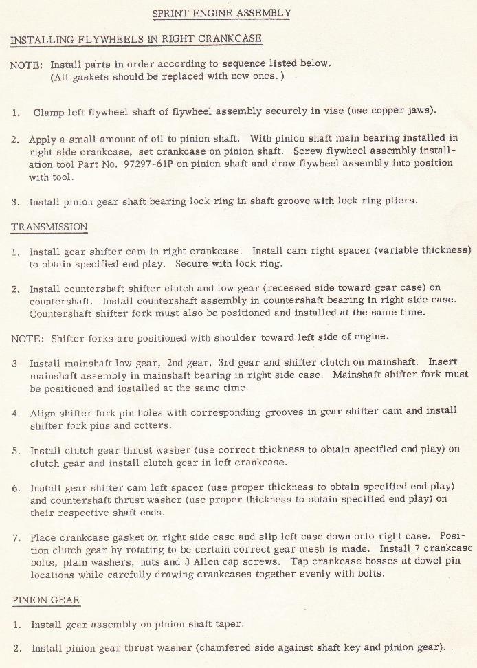
SPRINT ENGINE ASSEMBLY
INSTALLING FLYWHEELS IN RIGHT C+ANKCASE
NOTE: Install parts in order according to sequence listed below.(A11 gaskets should be replaced with new ones. )
X. Clamp Left flywheel shaft of flywheel assembly securely in vise (use copper jaws).
2. Apply a small amount of oll to pinion shaft. With pinion shaft main bearing installed inright side crankcase, set crankcase on pinion shaft. Screw flywheel assembly install-arion tool Part No. 97297 -61P on pinion shaft and draw flywheel assembly into positionwith tool.
3. Install pinion gear shaft bearing lock ring ln shaft groove with lock ring pliers.
TRANSMISSION
1. Install gear shifter cam in right crankcase. Install cam right spacer (variable thickness)to obtain specified end play. Secure with lock ring.
2. Install countershaft shifter clutch and low gear (recessed side toward gear case) on
countershaft. trnstall countershaft assembly in countershaft bearing in right side case.
Countershaft shifter fork must also be positioned and installed at the same time.
NOTE: Shifter forks are positioned with shoulder toward left side of engine.
3. Install mainshaft low gear, 2nd gear, 3rd gear and shifter clutch on mainshaft. Insertmainshaft assembly in mainshaft bearing in right side case. Mainshaft shifter fork mustbe positioned and installed at the same time.
4. Align shifter fork pin holes with corresponding grooves in gear shifter cam and installshifter fork pins and cotters.
5. Install clutch gear thrust washer (use correct thickness to obtain specified end play) on
clutch gear and install clutch gear in left crankcase.
6. Install gear shifter cam left spacer (use proper thickness to obtain specified end play)and countershaft thrust washer (use proper thickness to obtain specified end play) on
their respective shaft ends.
7. Place crankcase gasket on right side case and slip left case down onto right case. Posi-tion clutch gear by rotating to be certain correct gear mesh is made. Install 7 crankcasebolts, plain washers, nuts and 3 Allen cap screws. Tap crankcase bosses at dowel pinlocations while carefully drawing crankcases together evenly with bolts.
PINION GEAR
1. trnstall gear assembly on
2. Install pinion gear thrust
plnion shaft taper.
washer (chamfered side against shaft key and pinion gear).
t2
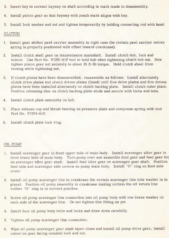
3. trnsert key in correct keyway on shaft according to mark made in disassembly.
4. Install pinion gear so that keyway with punch mark aligns'with key.
5. Instaltr lock washer and nut and tighten temporarily by holding connecting rod with hand.
CI-UTCH
1. Install gear shifter pawl carrier assembly in right case (be certaln pawl carrier returnspring is properly positioned with offset toward crankcase).
2, Install clutch shell gear on transmission mainshaft. Install clutch hub, lock andhubnut. Use Part No. 97291-61P tool to hold hub when tightening clutch hub nut. Nowtighten pinion gear nut securely to about 35 ft-lb torque. Hold clutch sheel fromturning while tightening nut.
3. If clutch plates have been disassembLed, reassemble as follows: Install alternatelyclutch drive plates and clutch driven plates (tined) until five drive plates and five drivenplates have been installed alternately on clutch backing plate. Install clutch outer plate.Fosition releasing disc on clutch backing plate studs and secure with locks and nuts.
4. Instali ciutch plate assembly on hub.
5. Place release cup and thrust bearing on pressure plate and compress spring with toolFart No. 97293-6LP.
6. Install clutch plate lock ring.
OIL PUMP
1. Install scavenger gear in front upper hole of main body. Install scavenger idler gear infront lower hole of main body. Turn pump over and assemble feed gear and feed gear keyon scavenger idler gear shaft. Install feed ldler gear on scavenger gear shaft. Positionfeed side and scavenger side covers on pump main body. Install "O" ring on feed sidecover.
2. Install oil pump scavenger line in crankcase (be certain scavenger line tube washer is inplace). Position oil pump assembly in crankcase making certain the oil return linerubber "O" ring is in correct position.
3. Screw oil pump scavenger line connection into oil pump body with one brass washer oneach side of the scavenger line. Do not tighten this fitting as yet.
4. Insert four oil pump body bolts and locks and draw down carefully'
5. Tighten oil pump scavenger line connection.
6. Wipe oil pump scavenger gear shaft taper clean and install oil pump drive gear' (smallcutout on gear facing outside) lock and nut.
13
2.
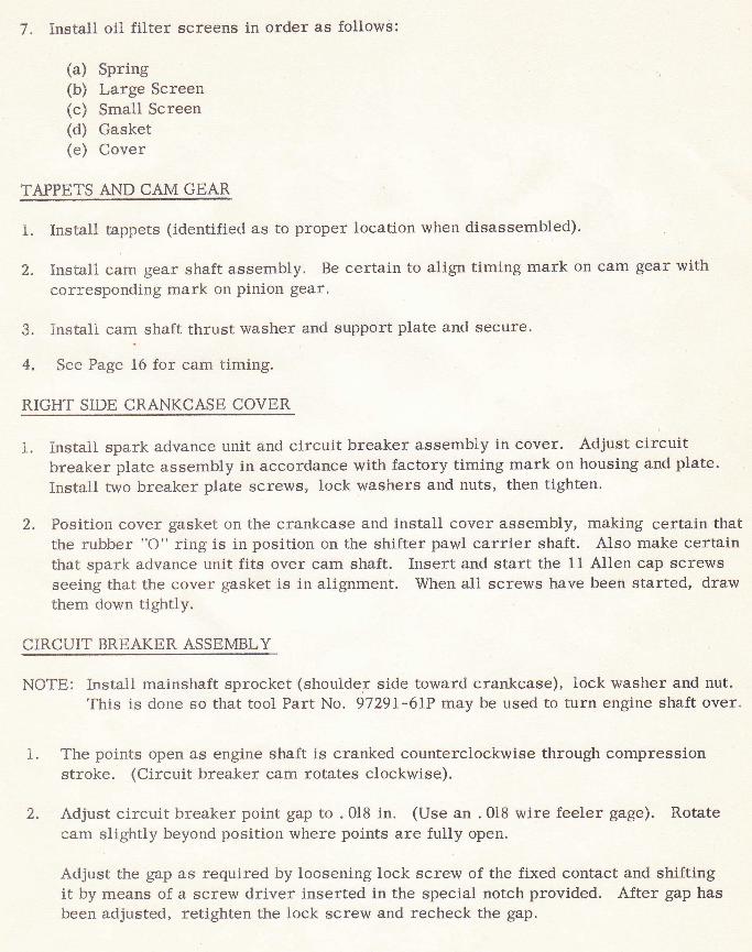
7 " Install oil filter screens
(a) SPring(b) Large Screen(c) SmaL1 Screen(d) Gasket(e) Cover
TAPPETS AND CAM GEAR
in order as follows:
1 trnstall tappets (identified as to proper location when disassernbled).
Instali cam gear shaft assembly. Be certain to align timing mark on cam gear withcorresponding mark on pinion gear'
3. Install cam shaft thrust washer and support plate and secure.
4. See Page 16 for cam timing.
RIGHT SIDE CRANKCASE COVER
i. Install spark advance unit and circuit breaker assembly in cover. Adjust circuitbreaker plate assembly in accordance with factory timing mark on housing and plate.
Install two breaker plate screws, lock washers and nuts, then tighten.
2. Fosition cover gasket on the crankcase and install cover assembly, making certain thatthe rubber "O" ring is in position on the shifter pawl carrier shaft. AIso make certainthat spark advance unit fits over cam shaft. Insert and start the 11 Allen cap screwsseeing that the cover gasket is in alignment. When all screws have been started, drawthern down tightly.
CIRCUIT BREAKER ASSEMBLY
NOTE: Install mainshaft sprocket (shoulder side toward crankcase), lock washer and nut.This is done so that tool Part No. 97291-61P may be used to turn engine shaft over.
I. The points open as engine shaft is cranked counterclockwise through compressionstroke. (Circuit breaker cam rotates clockwise).
Adjust circuit breaker point gap to .018 in. (Use an . 0lB wire feeler gage). Rotatecam slightly beyond position where points are fully open.
Adjust the gap as required by loosening lock screw of the fixed contact and shiftingit by means of a screw driver inserted in the special notch provided. After gap hasbeen adjusted, retighten the lock screw and recheck the gap.
2.
:i
I
'!,4
1.
A.
PISTON
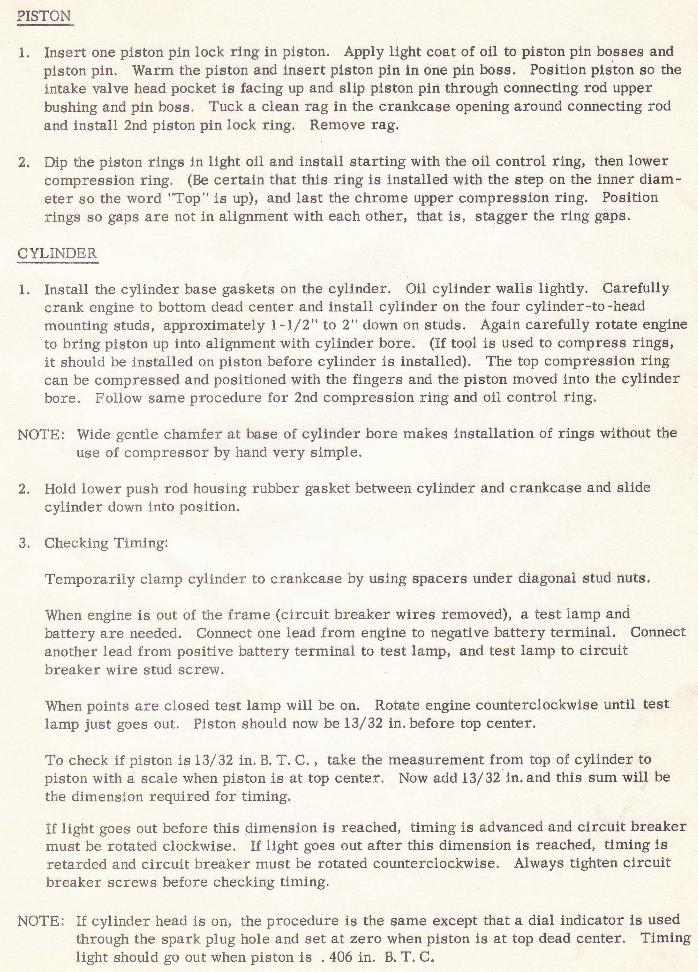
Insert one piston pin lock ring in piston. Apply light coat of oil to piston pin bosses andpiston pin. Warm the piston and insert piston pin in one pin boss. Position piston so theintake valve head pocket is facing up and slip piston pirt through connecting rod upperbushing and pin boss. Tuck a clean rag in the crankcase opening around connecting rodand install 2nd piston pin lock ring. Remove rag.
Dip the piston rings in iight oil and install starting with the oil control ring, then lowercompression ring. (Be certain that this ring is installed with the step on the inner diam-eter so the word "Top" is up), and last the chrome upper compression ring. Positionrings so gaps are not in alignment with each other, that is, stagger the ring gaps.
CYLINDER
tr- Install the cylinder base gaskets on the cylinder. Oil cylinder walls lightly. Carefullycrank engine to bottom dead center and install cylinder on the four cylinder-to-headmounting studs, approximately 1-I/2" to 2" down on studs. Again carefully rotate engineto bring piston up into alignment with cylinder bore. (If tool is used to compress rings,it should be installed on piston before cyllnder is installed). The top compression ringcan be compressed and positioned with the fingers and the piston moved into the cylinderbore. Follow same procedure for 2nd compression ring and oil control ring.
NOTE: Wide gentLe chamfer at base of cylindel bore makes installation of rings without theuse of compressor by hand very simple.
Hold lower push rod trousing rubber gasket between cylinder and crankcase and slidecylinder down into position.
Checking Timing:
Temporariiy clamp cylinder to crankcase by using spacers under diagonal stud nuts.
When engine is out of the frame (circuit breaker wires removed), a test lamp andbattery are needed. Connect one lead from engine to negative battery terminal. Connectanother lead from positive battery terminal to test lamp, and test lamp to circuitbreaker wire srud screw.
When points are closed test lamp will be on. Rotate engine counterclockwise until testlamp just goes out. Piston shoutrd now be L3/32 in. before top center.
To check if piston i,s L3/ 32 in. B. T. C. , take the measurement from top of cylinder topiston with d scale when piston is at top center. Now add 13/ 32 in. and this sum will bethe dimension required for timing.
If light goes out before this dimension is reached, timing is advanced and circuit breakermust be rotated clockwise. If light goes out after this dimension is reached, timing isretarded and circuit breaker rnust be rotated counterclockwise" Always tighten circuitbreaker screws before checking timing.
NOTE: If cyl.inder head is on, the procedure is the same except ttrat a dial indicator is usedthrougtr the spark ptug hole and set at zera when piston is at top dead center. Timinglight should go out when piston is . 406 in. B. T. C.
2.
I.
CYI,INDER. FIEAD
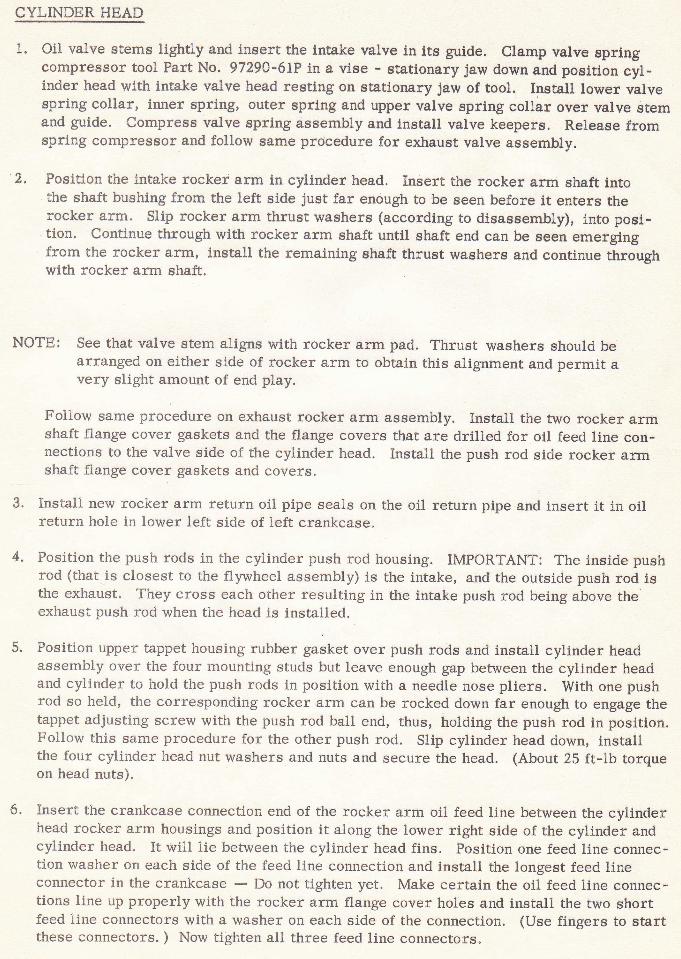
Oil valve stems lightly and insert the lntake valve in its guide. Clamp valve springcompressor tool Part No. 97290'6LP in a vise - stationary jaw down and position cyl-inder head with intake valve head resting on stationary jaw of tool. Install lower valvespring collar, inner spring, outer spring and upper valve spring collar over valve stemand guide. Compress valve spring assembly and install valve keepers. Release fromspring compressor and follow same procedure for exhaust valve assembly.
Fosition the lntake rocker arm in cytrinder head. Insert the rocker arnn shaft intothe shaft bushing frorn the left side just far enough to be seen before it enters therocker arrn. SIip rocker arm thrust washers (according to disassembly), into posi-tion' Continue through with rocker arm shaft until shaft end can be seen ernergingfrom the rocker arm, i.nstall the remaini.ng shaft thrust washers and continue throughwith rocker arrn shaft.
NOTE: See that valve stem aligns with rocker arm pad. Thrust washers should bearranged on either side of rocker arrn to obtain this alignment and permit avery slight arnount of end play.
Follow same procedure on exhaust rocker arm assembly. Install the two rocker arrnshaft flange cover gaskets and the flange covers that are drilled for oil feed line con-nections to the valve side of the cylinder head. Install the push rod side rocker armshaft flange cover gaskets and covers.
Install new rocker arm return oil pipe seals on the oil return pipe and insert it ln oilreturn hoie in lower left side of treft crankcase.
Fosition the push rods in the cylinder push rod housing. IMPORTANT: The inside pushrod (that is closest to the flywheei assembly) is the intake, and the outside push rod lsthe exhaust. They cross each other resulting in the intake push rod being above the'exhaust push rod when the head is installed.
Position upper tappet housing rubber gasket over push rods and install cylinder headassembly over the four mounting studs but leave enough gap between the cylinder headand cylinder to hold the push rods in position with a needle nose pliers. With one pushrod so held, the corresponding rocker arm can be rocked down far enough to engage thetappet adjusting screw with the push rod ball end, thus, holding the push rod in position.Follow this same procedure for the other push rod. Slip cylinder head down, installthe four cyiinder head nut washers and nuts and secure the head. (About 25 ft-lb torqueon head nuts).
Insert the crankcase connection end of the rocker arm oil feed line between the cylinderhead rocker arm housings and position it along the lower right side of the cylinder andcylinder head. trt will iie between the cyLinder head fins. Position one feed line connec-tion washer on each side of the feed line connection and install the longest feed lineconnector in the crankcase - Do not tighten yet. Make certain the oil feed line connec-tions line up properiy with the rocker arm flange cover holes and install the two shortfeed line connectors with a washer on each side of the connection. (Use fingers to startthese connectors. ) Now tighten all three feed line connectors.
2,
4.
5.
6.
T6
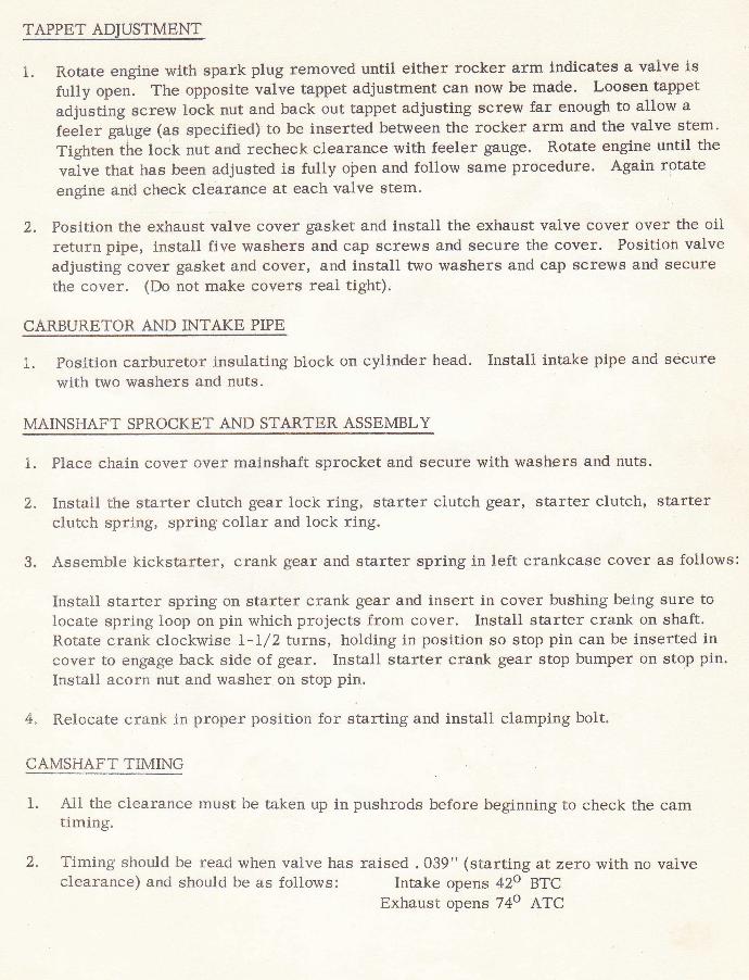
TAPPET ADJUSTMENT
1" R.otate engine with spark plug removed until either rocker arm indicates a valve isfully open. The opposite valve tappet adjustment can now be made. Loosen tappet
adjusting screw lock nut and back out tappet adjusting screw far enough to allow a
feeler gairge (as specified) to be inserted between the rocker arm and the valve stem.
Tighten the lock nut and recheck clearance with feeler gauge. Rotate engine until the
valve that has been adjusted is fully oiren and follow same procedure. Again rotate
engine and check clearance at each valve stem.
2. Position the exhaust valve cover gasket and install the exhaust valve cover over the oilreturn pipe, install five washers and cap screws and secure the cover. Position valveadjusting cover gasket and cover, and install two washers and cap scretts and securethe cover. (Do not make covers real tight).
CARBURETOR AND INTAKE PIPE
1. Position carburetor insulating block on cylinder head. Instali intake pipe and securewith two washers and nuts.
MAINSHAFT SPROCKET' AND STARTER ASSEMBLY
1. Flace chain cover over mainshaft sprocket and secure with washers and nuts.
2. Instail the starter clutch gear lock ring, starter cLutch gear, starter clutch, starterctrutch sprlng, spring collar and lock ring.
3. Assernble kickstarter, crank gear and starter spring in left crankcase cover as follows:
Install starter spring on starter crank gear and insert in cover bushing being sure tolocate spring loop on pin which projects from cover. Install starter crank on shaft.Rotate crank clockwise L-I/2 turns, holding in position so stop pin can be inserted incover to engage back side of gear. Install starter crank gear stop bumper on stop pin.Instail acorn nut and washer on stop pin.
4. Reiocate crank in proper position for starting and install clamping bolt.
CAMSHAFT TIMING
1. Ail the ci.earance rnust be taken up in pushrods before beginning to check the camtiming.
2. Timing should be read when valve has raised . 039 " ( starting at zero with no valveclearance) and should be as follows: Intake opens 4Zo BTC
Exhaust opens 74o ATC
t
L7
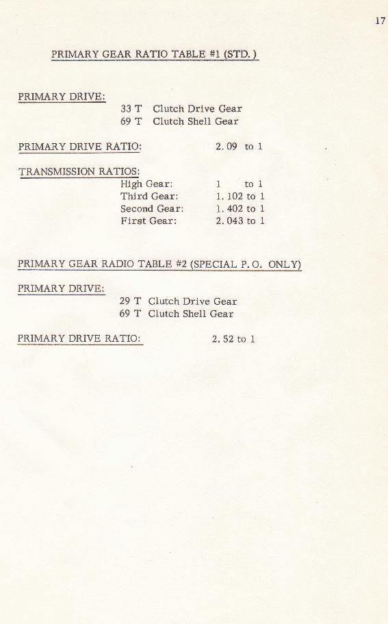
p4xnaaBy aE4R. 44{}a rg8t"s_tl-t$Tn, I
PRIMARY DRIVE: 93 T crutch Drive Gear69 f Clutch Shell Gear
PRIMARY DRM RATIO: ?.09 to 1
WHigh Gear: 1 to IThtrd Cear: t. 102 to ISecond Gear: 1.402 to I
' Firet Gear: 2.043 to I
PRIr\4ARYSEAR RADIO TABL,E #2 (SPECIAL p. O. Oi{I!y)
PRIMARY DRIVEI 29 T cruteh Df,ive Gear69 T Ctutch Shell Gear
PRIMARY DRIVE RATIO: 2. 52 to I
18
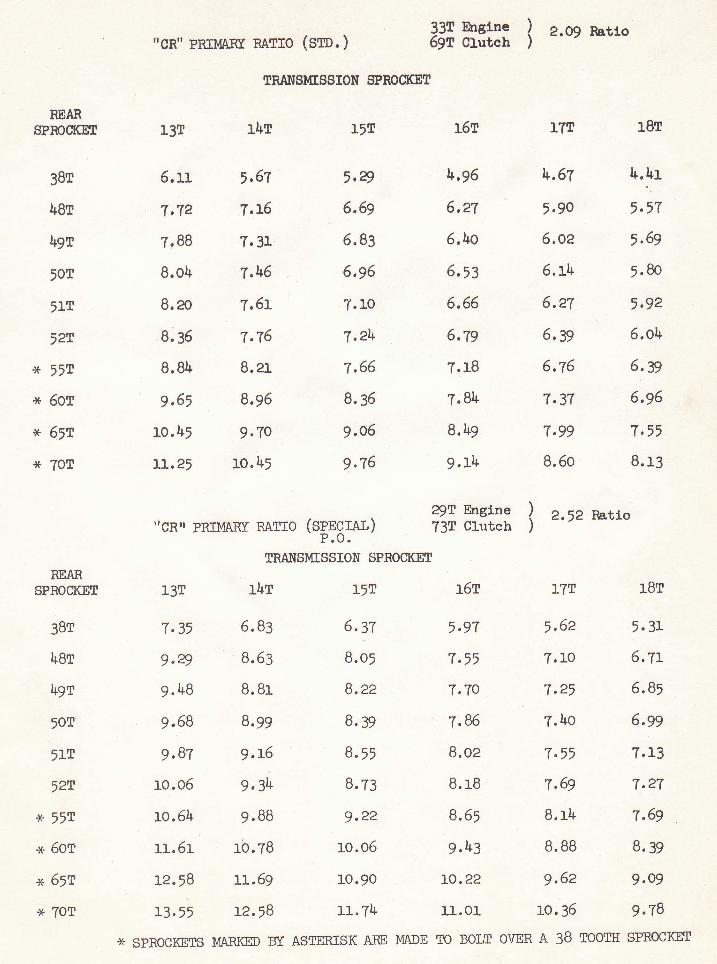
33[ hrglne59f ctutcu l t.* Ratto
"cR" PRTldASty nATro (sm. )
TNAI{SMTS$ION SFNOCI( T
nEARSPNOCKET
38r
hBr
49r
507
5tr
52r
* 557
x 6or
x 65I
x fOT
NEANSPNOCKET
3BT
h8r
49r
507
51r
527
x 557
x 6or
x 65't
x IOT
13r
5.rI
T.1/2
T'88
8.oh
8.ao
8.36
8.81+
9,65
ro.h5
LL,25
IhT
5,67
T,L5
7.31
7,1+6
"1,6L
7,76
8.al
8,96
9,70
lo.lr5
'rcnr PRtltAKr RArlo (tffgy")
I5[
,,ry6,69
6.83
6,96
7.lo
'l,?It
7.66
8.35
9,06
9.76
SRANSMISSION SPROSKET
I5T
6.?r
B"05
B.zz
8,39
8.>l
8.73
9.22
ro.o5
10,90
u. T4
r5r
5.97
T.r5
7.70
7,86
8.02
B. r8
8.6,
9.1+3
LO.22
11.OL
r8r
,*,lr
,.57,
,,69
5. Bo
5.g2
6.ob
6,39
6,96
7,55
8.13
187
5. 31
7.27
T,69
r5r
l+,96
6,a7
6.to
6.i3
6.66
6,79
T.IB
T;8lt
8.b9
9.Il+
2pT Engtne73T Clutch
I?T
h,67
5,90
6,oz
6. Lb
6,aT
5.39
6,76
7,37
7,99
B.60
I z.!z Ratlo
I7T
5.62
7,69
B.rb
13T rl+r
7.35 6. 83
9.4 8.63
9.48 B.Br
9.68 8.99
9,87 g.L6
tO.O5 g,3l+
ro.54 9.BB
u.6r rb.TB
Lz.jB tl-.6g
u. >i La,5g
T.1o 6.TL
7.25 6.8,
?.1+o 6.99
7.5' ?.13
B.8B 8.39
9.62 9,o9
10,35 g,7B
* spRocKETs I{ABIGD tr AstERIsK AfiE MADE To BoLT o\i:ER A 38 TooTH SPROcKET
rI
19
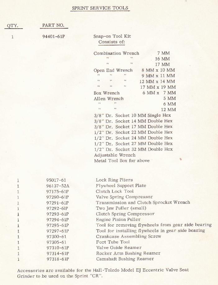
SPRINT SERVICE TOOLS
ATL-
1I
PART NO.
9440r-6rP Snap-on Tool KitConsists of:
Comblnation Wrench
tt . It
Open End Wrenchtt tt
. tt
tt lr ll
tt tt tt
Box WrenchAl1en Wrench
tt rt
lr ll
7MM16 MM17 MM
8MMxl0MM9MMx11 MM
12MMx14MM17MMx19MM6MMx 7MM
5MM6MM
12 MM
95017-6196137-52A97L75-6rP97290-6LP9729L-6rP97292-6rP97293-6rP97294-6LP97295-6LP97297 -6rP97300-6197305-61973LO-6tP973t4-6rP97318 -6lP
3/8" Dr. Socket 10 MM Single Hex3/8" Dr. Socket 14 MM Double Hex3/8" Dr. Socket 17 MM Double Hexl/2" Dr. Socket 22 MM Double Hex!/2" Dr. Socket 24 MM Doub1e HexL/2" Dr. Socket 27 MM Double Hexl/2" Dr. Socket 32 MM Double HexAdjustable WrenchMetal Tool Box for above
Lock Ring PliersFlywheel Support PlateClutch Lock ToolValve Spring CompressorTransmission and Clutch Sprocket WrenchTwo Jaw Puller (small)Clutch Spring CompressorEngine. Pinion PullerTool for removing flywheels from gear side bearingTool for installing flywheels in gear side bearingCrankcase Assembling ScrewFort Tube ToolValve Guide ReamerRocker Arm Bushing ReamerCamshaft Bushing Reamer
Accessories are available for the Hall-Toledo Model EJ Eccentric Valve Seat
Grinder to be used on the Sprint "CR".