rexton service manual engine
TRANSCRIPT

ENGINE
SERVICE MANUAL
PYUNGTAEK, KOREA

GENERAL INFORMATION
SERVICEMANUAL(vol. 1 of 2)
SECTION INDEX
ENGINE ASSEMBLY DI01
DI0A
PYUNGTAEK, KOREA
SSANGYONG MOTOR CO., LTD.
REXTON
FOREWORD
This manual includes procedure for maintenance,adjustment, service operation and removal andinstallation of components.
All information, illustrations and specificationscontained in this manual are based on the latestproduct information available at the time of manualapproval.
The right is reserved to make changes at any timewithout notice.
VOLUME 1 OF 2
ENGINE HOUSING DI02
INTAKE SYSTEM DI03
EXHAUST SYSTEM DI04
LUBRICATION SYSTEM DI05
COOLING SYSTEM DI06
FUEL SYSTEM DI07
ENGINE CONTROL SYSTEM DI08
ELECTRIC DEVICES ANDSENSORS DI09
DIAGNOSIS DI10

DI ENGINE
GENERAL INFORMATION....................DI0A
ENGINE ASSEMBLY ............................. DI01
ENGINE HOUSING ................................ DI02
INTAKE SYSTEM................................... DI03
EXHAUST SYSTEM............................... DI04
LUBRICATION SYSTEM ....................... DI05
COOLING SYSTEM ............................... DI06
FUEL SYSTEM ...................................... DI07
ENGINE CONTROL SYSTEM............... DI08
ELECTRIC DEVICES AND SENSORS . DI09
DIAGNOSIS ........................................... DI10
CONTENTS

GENERAL INFORMATION
SECTION DI0A

DI0A-1
CHANGED BY
EFFECTIVE DATE
AFFECTED VIN
GENERAL INFORMATIONDI ENG SM - 2004.4
GENERAL INFORMATION
00SECTION DI0A
Table of Contents
CLEANNESS ....................................... DI0A-3
STRUCTURE ...................................... DI0A-8
ENGINE CONTROLS ....................... DI0A-11
ECU related components ..............DI0A-11
Engine and sensors ..................... DI0A-12
Electrical components andpre heating system ...................... DI0A-13
INTAKE SYSTEM ............................. DI0A-14
Intake air flow chart ...................... DI0A-15
INTAKE SYSTEM ............................. DI0A-16
Exhaust air flow chart ................... DI0A-17
LUBRICATION SYSTEM .................. DI0A-18
COOLING SYSTEM ......................... DI0A-19
Coolant flow chart ........................ DI0A-20
FUEL SYSTEM ................................. DI0A-21
Fuel supply system ...................... DI0A-22
GENERAL SPECIFICATIONS........... DI0A-23
Vehicle specifications ................... DI0A-23
Maintenance ................................ DI0A-26
VEHICLE IDENTIFICATION.............. DI0A-28
HOW TO USE AND MAINTAIN WORKSHOPMANUAL ........................................... DI0A-30
Consists of workshop manual ...... DI0A-30
Manual description ...................... DI0A-30
Guidelines for service worksafety ........................................... DI0A-31
Lifting points ................................. DI0A-36
Tightening torque of standardbolts.............................................. DI0A-37


DI0A-3
CHANGED BY
EFFECTIVE DATE
AFFECTED VIN
GENERAL INFORMATIONDI ENG SM - 2004.4
The fuel system for DI engine consists of transfer (low pressure) line and high pressure line. Its highest pressurereaches over 1600 bar. Some components in injector and HP pump are machined at the micrometer 100 µm ofpreciseness. The pressure regulation and injector operation are done by electric source from engine ECU.Accordingly, if the internal valve is stucked due to foreign materials, injector remains open. Even in this case, theHP pump still operates to supply high pressurized fuel. This increases the pressure to combustion chamber (over250 bar) and may cause fatal damage to engine.
You can compare the thickness of injector nozzle hole and hair as shown in below figure (left side). The right sidefigure shows the clearance between internal operating elements.
Cleanness of DI Engine Fuel System and Service Procedures
The core elements of fuel system has very high preciseness that is easily affected by dust or very small foreignmaterial. Therefore, make sure to keep the preliminary works and job procedures in next pages. If not, lots ofsystem problems and claims may arise.
CLEANNESS
Y220_0A035
Hair
Nozzle hole
Valve actuator lift: 0.028 mm
Diameter: 0.40 mm
Operatingclearance:0.002 mm
Diameter:
2.0 mm

DI0A-4
CHANGED BY
EFFECTIVE DATE
AFFECTED VIN
GENERAL INFORMATIONDI ENG SM - 2004.4
1. Always keep the workshop and lift clean (especially, from dust).
2. Always keep the tools clean (from oil or foreign materials).
3. Wear a clean vinyl apron to prevent the fuzz, dust and foreign materials from getting into fuel system. Washyour hands and do not wear working gloves.
4. Follow the below procedures before starting service works for fuel system.
Job procedures
Carefully listen the symptoms and problems from customer.
Visually check the leaks and vehicle appearance on the wiring harnessesand connectors in engine compartment.
Perform the diagnosis proceee with Scan-i(refer to “DIAGNOSIS” section in this manual).
Locate the fault. If the cause is from fuel system (from priming pump toinjector, including return line), follow the step 1 through step 3 above.
5. If the problem is from HP pump, fuel supply line or injector, prepare the clean special tools and sealing capsto perform the diagnosis for DI engine fuel system in “DIAGNOSIS” section in this manual. At this point,thoroughly clean the related area in engine compartment.
Notice
Clean the engine compartment before starting service works.
Tool kit for high pressure line Took kit for low pressure line Removal tool box and cap kits

DI0A-5
CHANGED BY
EFFECTIVE DATE
AFFECTED VIN
GENERAL INFORMATIONDI ENG SM - 2004.4
6. Follow the job procedures. If you find a defective component, replace it with new one.
Y220_0A039
Fuel pressure sensor
Common rail
Injectionpipe
Injector
High pressure pump
IMV valve
Transfer pump and highpressure pump
Fuel temperature sensor
Fuel tank
Fuel filter
Primingpump
Water separator
Water detection sensor
Disconnect the negative battery cable.
Plug the disconnected parts with sealing caps, and remove the caps immediatelybefore replacing the components.
Once disconnected, the fuel pipes between HP pump and fuel rail and between fuel railand each injector should be replaced with new ones. The pipes should be tightened tospecified tightening torques during installation. Over or under torques out of specifiedrange may cause damages and leaks at connections. Once installed, the pipes have beendeformed according to the force during installtion, therefore they are not reusable.
The copper washer on injector should be replaced with new one. The injector holder boltshould be tightened to specified tightening torque as well. If not, the injection point may bedeviated from correct position, and it may cause engine disorder.
Supply lineReturn line
Cap position
Use special tools and torque wrench to perform the correct works.
For safety reasons: check pressure is low before opening the HP systems (pipes)

DI0A-6
CHANGED BY
EFFECTIVE DATE
AFFECTED VIN
GENERAL INFORMATIONDI ENG SM - 2004.4
7. Plug the removed components with clean andundamaged sealing caps and store it into the box tokeep the conditions when it was installed.
8. Clear the high pressure offset value by Scan-100 afterreplacing the high pressure pump.
9. To supply the fuel to transfer line of HP pump pressthe priming pump until it becomes hard.
10. Check the installed components again and connectthe negative battery cable. Start the engine and checkthe operating status.
11. With Scan-i, check if there are current faults and erasethe history faults.
Note
For details, refer to “DI10 Diagnosis teable”.
Y220_0A040
Y220_0A041
Y220_0A042
Priming pump
Warning
Do not crank engine before having filled pump.

DI0A-7
CHANGED BY
EFFECTIVE DATE
AFFECTED VIN
GENERAL INFORMATIONDI ENG SM - 2004.4
SYSTEM SUPPLEMENT AND REMEDY AGAINST WATER IN FUELAs mentioned above, some gas stations supply fuel withexcessive than specified water. In the conventional IDIengine, excessive water in the fuel only causes droppingengine power or engine hunting. However, fuel system inthe DI engine consists of precise components so water inthe fuel can cause malfunctions of HP pump due to poorlubrication of pump caused by poor coating film during highspeed pumping and bacterization (under long period parking).To prevent problems can be caused by excessive water infuel, water separator is installed inside of fuel filter. Whenfuel is passing filter, water that has relatively bigger specificgravity is accumulated on the bottom of the filter.
SYSTEM SUPPLEMENT AGAINST PARAFFIN SEPARATION.In case of Diesel fuel, paraffin, one of the elements, can be separated from fuel during winter and then can stick onthe fuel filter blocking fuel flow and causing difficult starting finally. Oil companies supply summer fuel and winterfuel by differentiating mixing ratio of kerosene and other elements by region and season. However, above phenomenoncan be happened if stations have poor facilities or sell improper fuel for the season.In case of DI engine, purity of fuel is very important factor to keep internal preciseness of HP pump and injector.Accordingly, more dense mesh than conventional fuel filter is used. To prevent fuel filter internal clogging due toparaffin separation, SYMC is using fuel line that high pressure and temperature fuel injected by injector returnsthrough fuel filter to have an effect of built-in heater (see fuel system).
DI Engine and Its Expected Problems and Remedies Can be Causedby Water in Fuel
Y220_0A041
If water in the separator on the fuel filter exceeds a certain level, it will be supplied to HP pump with fuel, so theengine ECU turns on warning light ( ) on the meter cluster and buzzer if water level is higher than a certain level.
Due to engine layout, a customer cannot easily drain water from fuel filter directly, so if a customer checks in tochange engine oil, be sure to perform water drain from fuel filter. (See fuel system for details.)

DI0A-8
CHANGED BY
EFFECTIVE DATE
AFFECTED VIN
GENERAL INFORMATIONDI ENG SM - 2004.4
Front view
Rear view
Y220_0A001
STRUCTURE
1. TVD (Torsional Vibration Damper)
2. Air conditioner compressor
3. Power steering pump pulley
4. Idle pulley
5. Water pump pulley
6. Alternator
7. Cooling fan pulley & viscos clutch
8. Aut tensioner pulley
9. Auto tensioner
10. Poly-groove belt
11. Cam position sensor
12. Drive plate (M/T: DMF)
13. Oil filter housing
14. Vacuum pump
15. Crank position sensor
16. EGR valve
17. Power steering pump
18. EGR center pipe

DI0A-9
CHANGED BY
EFFECTIVE DATE
AFFECTED VIN
GENERAL INFORMATIONDI ENG SM - 2004.4
Top view
Y220_0A002
19. Cylinder head cover
20. Intake manifold
21. Water outlet port
22. Common rail
23. Fuel pressure sensor
24. Fuel pipe
25. Injector
26. Fuel return line
27. Oil filler cap
28. Glow plug
29. Booster pressure sensor
30. Oil separator
31. Oil dipstic
32. EGR center pipe

DI0A-10
CHANGED BY
EFFECTIVE DATE
AFFECTED VIN
GENERAL INFORMATIONDI ENG SM - 2004.4
Right side view
Left side view
Y220_0A003
33. Cylinder head
34. Cylinder block
35. Oil pan
36. Drain plug
37. Turbocharger
38. EGR - RH pipe
39. Oil separator
40. Oil dipstic
41. HP pump
42. Turbocharger vacuum modulator
43. EGR valve vacuum modulator
44. EGR valve
45. Exhaust manifold

DI0A-11
CHANGED BY
EFFECTIVE DATE
AFFECTED VIN
GENERAL INFORMATIONDI ENG SM - 2004.4
HFM sensor/intake airtemperature sensor
Pre heating time relay Main relay
ECU/barometric sensor Cam position sensorFuel filter
(water detection sensor) Accelerator pedal sensor
ECU RELATED COMPONENTS
ENGINE CONTROLS
Y220_0A004

DI0A-12
CHANGED BY
EFFECTIVE DATE
AFFECTED VIN
GENERAL INFORMATIONDI ENG SM - 2004.4
Common rail
Fuel pressure sensor
Booster pressure sensorCamshaft positionsensor
Knock sensor (2)
Crankshaft positionsensorInjector
HP pump
Glow plug
Coolant temperaturesensor
ENGINE AND SENSORS
Y220_0A005

DI0A-13
CHANGED BY
EFFECTIVE DATE
AFFECTED VIN
GENERAL INFORMATIONDI ENG SM - 2004.4
Y220_0A006
ELECTRICAL COMPONENTS AND PRE HEATING SYSTEM
Glow plug Pre heating time relay
BatteryFuse box
AlternatorStarter motor

DI0A-14
CHANGED BY
EFFECTIVE DATE
AFFECTED VIN
GENERAL INFORMATIONDI ENG SM - 2004.4
Air cleaner assembly Intake duct hoseHFM sensor Intake manifold
Intake outlet hose Turbocharger Intercooler Inlet hose
Y220_0A007
INTAKE SYSTEM

DI0A-15
CHANGED BY
EFFECTIVE DATE
AFFECTED VIN
GENERAL INFORMATIONDI ENG SM - 2004.4
Intake valve (in combustion chamber)
Intake manifold
Intake hose (inner)Intake hose (outlet) Intercooler
HFM sensor
Turbo-charger(compressor)
Air cleaner side
Engine
INTAKE AIR FLOW CHART
Y220_0A008

DI0A-16
CHANGED BY
EFFECTIVE DATE
AFFECTED VIN
GENERAL INFORMATIONDI ENG SM - 2004.4
Muffler Exhaust manifold EGR valve
Vacuum modulatorTurbocharger Catalytic converter EGR pipe
Y220_0A009
INTAKE SYSTEM

DI0A-17
CHANGED BY
EFFECTIVE DATE
AFFECTED VIN
GENERAL INFORMATIONDI ENG SM - 2004.4
Exhaust pipeCatalytic converter Muffler
Ambientair
Exhaust gas
EGR vacuummodulator
To turbochargerbooster
Turbochargerbooster vacuummodulator
EGR valve
EGR pipe
Turbocharger booster
Turbocharger(turbine side)
Exhaust manifold
EXHAUST AIR FLOW CHART
Y220_0A010

DI0A-18
CHANGED BY
EFFECTIVE DATE
AFFECTED VIN
GENERAL INFORMATIONDI ENG SM - 2004.4
Oil dipstic PCV valve Engine oil filterhousing
Engine oil pump Oil pan Engine oil cooler Engine oil pressureswitch
Cylinder head cover
Y220_0A011
LUBRICATION SYSTEM

DI0A-19
CHANGED BY
EFFECTIVE DATE
AFFECTED VIN
GENERAL INFORMATIONDI ENG SM - 2004.4
Y220_0A013
COOLING SYSTEM
Coolant reservoir
Radiator assembly Cooling fan and fanclutch
Water pump

DI0A-20
CHANGED BY
EFFECTIVE DATE
AFFECTED VIN
GENERAL INFORMATIONDI ENG SM - 2004.4
Coolant reservoir
Thermostat
Heater
Intake manifold
Coolant outlet port
Outlet hose
Radiator
Cooling fan
Inner hose
Water pump
Y220_0A014
COOLANT FLOW CHART
Oil cooler

DI0A-21
CHANGED BY
EFFECTIVE DATE
AFFECTED VIN
GENERAL INFORMATIONDI ENG SM - 2004.4
Fuel return hose Fuel pressure pipe Common rail Fuel filter
Injector HP pump Priming pump
Y220_0A015
FUEL SYSTEM
DI0A-22
CHANGED BY
EFFECTIVE DATE
AFFECTED VIN
GENERAL INFORMATIONDI ENG SM - 2004.4
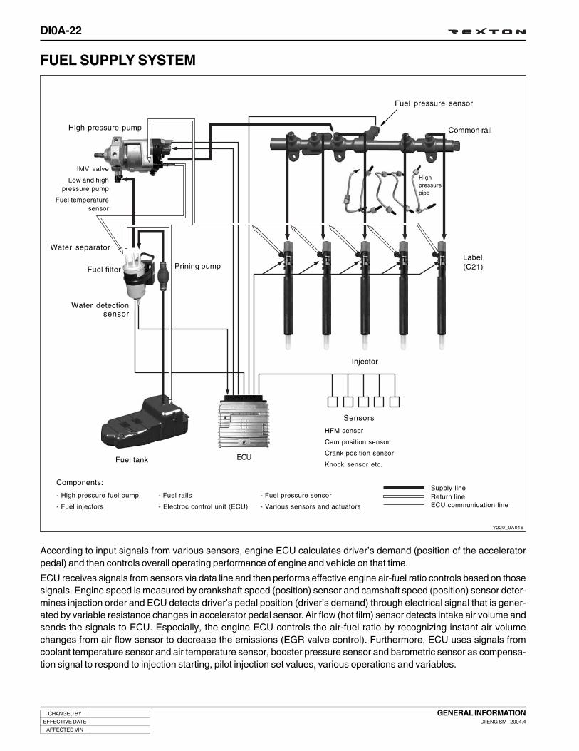
FUEL SUPPLY SYSTEM
Y220_0A016
According to input signals from various sensors, engine ECU calculates driver’s demand (position of the acceleratorpedal) and then controls overall operating performance of engine and vehicle on that time.
ECU receives signals from sensors via data line and then performs effective engine air-fuel ratio controls based on thosesignals. Engine speed is measured by crankshaft speed (position) sensor and camshaft speed (position) sensor deter-mines injection order and ECU detects driver’s pedal position (driver’s demand) through electrical signal that is gener-ated by variable resistance changes in accelerator pedal sensor. Air flow (hot film) sensor detects intake air volume andsends the signals to ECU. Especially, the engine ECU controls the air-fuel ratio by recognizing instant air volumechanges from air flow sensor to decrease the emissions (EGR valve control). Furthermore, ECU uses signals fromcoolant temperature sensor and air temperature sensor, booster pressure sensor and barometric sensor as compensa-tion signal to respond to injection starting, pilot injection set values, various operations and variables.
Fuel pressure sensor
Highpressurepipe
Common rail
Label(C21)
Injector
Sensors
HFM sensor
Cam position sensor
Crank position sensor
Knock sensor etc.ECUFuel tank
Prining pumpFuel filter
Water separator
High pressure pump
IMV valve
Low and highpressure pump
Fuel temperaturesensor
Components:
- High pressure fuel pump
- Fuel injectors
- Fuel rails
- Electroc control unit (ECU)
Supply line- Fuel pressure sensor
- Various sensors and actuators
Return lineECU communication line
Water detectionsensor

DI0A-23
CHANGED BY
EFFECTIVE DATE
AFFECTED VIN
GENERAL INFORMATIONDI ENG SM - 2004.4
VEHICLE SPECIFICATIONS
Vehicle Dimension
Y220_0A017
(mm)
GENERAL SPECIFICATIONS

DI0A-24
CHANGED BY
EFFECTIVE DATE
AFFECTED VIN
GENERAL INFORMATIONDI ENG SM - 2004.4
Specifications
4,720 (4,785)
1,870
1,760 (1,830)
AT: 2450 (2510), MT: 2405 (2465)
AT: 1995 (2055), MT: 1950 (2010)
5.6
200
Diesel
80
D27DT
5/18:1
2,696 cc
DOHC
170 ps/4,000 rpm
34.7 kg•m/1,800 rpm
ATDC 4° ± 1°(at idle)
760 ± 50 rpm
Water-cooled/forced circulation
Approx. 11.5
Gear pump, forced circulation
9.3
Turbo charger, air-cooled
Remote control, floor change type
1st
2nd
3rd
4th
5th
Rev.
1st
2nd
3rd
4th
5th
Rev. 1st
Rev. 2nd
General Overall length (mm)
Overall width (mm)
Overall height (mm)
Gross vehicle weight (kg)
Curb weight (kg)
Min. turning radius (m)
Ground clearance (mm)
Fuel
Fuel tank capacity
Model
No. of cyl./Compression ratio
Total displacement
Camshaft arrangement
Max. power
Max. torque
Injection timing
Idle speed
Cooling system
Coolant capacity
Lubrication
Max. oil capacity
Turbo charger and cooling type
Type
Model
Type
Systems Items Diesel Remark
( ): optionalitem
IDI Engine 4.007
2.367
1.473
1.000
0.872
3.700
DI Engine 4.315
2.475
1.536
1.000
0.807
3.591
Electronic
Floor change type
2.742
1.508
1.000
0.708
-
2.429
-
2.742
1.508
1.000
0.708
-
2.429
-
3.595
2.186
1.405
1.000
0.831
3.162
1.926
Engine
Manualtransmission
Automatictransmission

DI0A-25
CHANGED BY
EFFECTIVE DATE
AFFECTED VIN
GENERAL INFORMATIONDI ENG SM - 2004.4
Specifications (Cont’d)
Systems
Transfercase
Clutch
Powersteering
Front axle
Rear axle
Brake
Suspension
Airconditioner
Electrical
Items
Model
Type
Type
Disc type
Type
Drive shaft type
Axle housing type
Drive shaft type
Axle housing type
Master cylinder type
Booster type
Parking brake
Front
Rear
Refrigerant
Compressor type
Battery type/Capacity (V-AH)
Starter capacity (V-kW)
Alternator capacity (V-A)
Diesel
Part-time
Planetary gear type
1.000 : 1
2.483 : 1
Hydraulic [A/T: Torque converter]
Dry single diaphragm type
[A/T: 3 elements 1 stage 2 phases]
Rack and pinion
36° 17'
32° 40'
Ball joint type
Build-up type
Semi-floating type
Build-up type
Tandem type
Vacuum booster
Disc
Drum (Disc)
Cable type (internal expansion)
Wishbone + Coil spring
5-link + Coil spring
R134a
Vane type
MF / 12 - 90
Diesel : 12 - 2.2, Gasoline : 12 - 1.8
12 - 75 (12 - 90)
12 - 140 (12 - 115)
12 - 115
Remark
High
Low
Inner
Outer
Inner
Outer
( ): optional item
IDI
DI
Gasoline
Type
Steering angle
Gear ratio

DI0A-26
CHANGED BY
EFFECTIVE DATE
AFFECTED VIN
GENERAL INFORMATIONDI ENG SM - 2004.4
Gasolineengine
MAINTENANCE
Major Components and Service Interval* Use only Ssangyong Genuine Parts.
Components Service Interval Remarks
Initial change: 10,000 km
Replace at every 15,000 km
Initial change: 5,000 km
Replace at every 10,000 km or 12 months
Replace at every 60,000 km or 3 years
Initial inspection: 1,000 km
Inspect at every 20,000 km, replace if necessary
Inspect at every 10,000 km, check or adjust if necessary
Clean at every 15,000 km,
Replace at every 60,000 km
Initial clean: 5,000 km,
Clean at every 10,000 km, replace ifnecessary,
Replace at every 30,000 km
Replace at every 60,000 km
Replace at every 30,000 km (Drain the water from fuel filter at every 10,000 km)
Replace at every 40,000 km
Inspect at every 30,000 km or 1 year,replace if necessary (replace at every60,000 km if the vehicle is operatedunder severe conditions)
Inspect at every 10,000 km,
Replace at every 60,000 km
Inspect at every 10,000 km,
Replace at every 60,000 km (but, frequently chexk the leaks)
Replace at every 30,000 km
Replace at every 10,000 km
Replace at every 60,000 km
Engineoil andoil filter
DI dieselengine
IDI dieselengine
Coolant
Brake pipe and hose
Brake pad, shoe anddisc
More frequent maintenance is required ifthe vehicle is operated under severecondition.Severe conditions?- Frequent low-speed operation as in
stop-and-go traffic- When most trips are less than 6 km (in
winter, less than 16 km)- Driving in sandy, dusty, and salty road- Driving in mountainous areas- Extensive idling or high load operation
such as towing a trailer
Daily Weekly
O -
O -
O -
O -
- -
- -
Aircleanerelement
Fuel filter
If vehicle is operated under dusty or sandyarea, frequently clean and inspect the aircleaner system. If necessary, replace the aircleaner element.
4-speed
5-speed
More frequent maintenance is required if thevehicle is operated under severe condition.- Driving in unpaved road- Towing a trailer
Manual transmissionoil
Transfer case oil
Axle oil
Air conditioner airfilter
More frequent maintenance is required if thevehicle is operated under severe condition.- Driving in sandy, dusty, and unpaved road- Excessive operation of air conditioner or
heater
Spark plug (gasolineengine)
Auto-matictransmis-sion oil
Gasolineengine
DI dieselengine
IDI dieselengine
Gasolineengine
DI dieselengine
IDI dieselengine
- O
- O
- O
- -
- -
- -
- -
- -
- -
- -
- -
- -
- -

DI0A-27
CHANGED BY
EFFECTIVE DATE
AFFECTED VIN
GENERAL INFORMATIONDI ENG SM - 2004.4
Lubrication Chart
Lubricant Capacity Classification
Diesel
Engine oil
Gasoline
API : CG grade or above,
ACEA : B2, B3 or B4
MB sheet : 229.1/3 (preferable)
MB sheet No. 224.1
API : SJ grade or above,
ACEA : A2 or A3
MB sheet : 229.1/3 (preferable)
MB sheet No. 224.1
IDI Engine
DI Engine
G23D
G32D/G28D
6.0 ~ 8.0 L
6.8 ~ 8.3 L
5.5 ~ 7.5 L
7.0 ~ 9.0 L
Qualityclass**
Viscosity
Qualityclass**
Viscosity
IDI Engine
DI Engine
G23D
G32D/G28D
10.5 ~ 11.0 L
11.0 ~ 12.0 L
10.0 ~ 10.5 L
11.3 ~ 11.5 L
MB sheet 325.0
BASF GLYSANTIN G05-11,
HOECHST GENANTIN SUPER 8023/14
ATF DEXRON® II, III,
ATF S-2, S-3, S-4, TOTAL FLUID ATX
SAE J 1703, DOT 3 or DOT 4
ATF DEXRON® II, III
CASTROL TQ 95
SHELL or FUCHS ATF 3353
ATF DEXRON® II, III,
ATF S-4, TOTAL FLUID ATX
SAE 80W/90, API GL-5
SHELL Retinax “A” grade
ALVANIA EP#2
Engine coolant(Antifreeze and soft water mixed)
Manual transmission oil
Brake/Clutch fluid (Level must bemaintained between MAX & MINlevel)
Power steering fluid
Automatic transmission fluid
Transfer case fluid
4WD: 3.6 L, 2WD: 3.4 L
Properly
1.1 L
4-speed: 9.5 L
5-speed: 8.0 L
1.2 ~ 1.4 L
1.4 ~ 1.5 L
1.4 ~ 1.5 L
1.4 ~ 1.5 L
IDI Engine
DI Engine
Gasoline
Front
Rear
Part time
Part time
Full time(TOD)
Full time(TOD)
Axle fluid
Wheel bearing grease
Propeller shaft grease - Front/Rear
1.4 ~ 1.5 L
2.2 L
Properly
Properly
IDI: Indirect Injection
DI: Direct Injection
* Please contact Ssangyong Dealer for approved alternative fluid.
** In only case not available MB 229.1 or 229.3, API or ACEA oil may be accepted, however it would rather recommendto shorten the change interval around 30%.

DI0A-28
CHANGED BY
EFFECTIVE DATE
AFFECTED VIN
GENERAL INFORMATIONDI ENG SM - 2004.4
1. Vehicle identification NumberVehicle identification number (VIN) is is on the right frontaxle upper frame.
[KPTPOA19S1P 122357]
K .. Nation (K: Korea)
P .. Maker Identification (P: Ssangyong Motor Company)
T .. Vehicle Type (T: Passenger car - 4WD)
P .. Line Models (P: Rexton)
O . Body Type (O: 5-door)
A .. Trim Level (A: Standard, B: Deluxe,C: Super deluxe)
1 .. Restraint System (0: No seatbelts, 1: 3-pointseatbelts, 2: 2-point seatbelt)
9 .. Engine Type (9: 3199cc, In-line 6 cylinders, Gasoline E32)(D: 2874cc, Il-line 5 cylinders, Diesel)
S .. Check Digit (S: All area except North America)
1 .. Model Year (1: 2001, 2: 2002, 3: 2003)
P .. Plant Code (P: Pyungtaek plant)
122357 (Production serial number)
2. Certification LabelThe certification label is affixed on the bottom of driver’s sideB-pillar.
Y220_0A018
Y220_0A019
VEHICLE IDENTIFICATION

DI0A-29
CHANGED BY
EFFECTIVE DATE
AFFECTED VIN
GENERAL INFORMATIONDI ENG SM - 2004.4
3. Engine Serial NumberThe engine serial number is stamped on the lower area ofcylinder block in exhaust manifold side.
4. Manual Transmission NumberThe transmission label is affixed on the upper area of clutchhousing.
Y220_0A020
5. Automatic Transmission NumberThe transmisson label is affixed on the right area of transmis-sion housing.
Y220_0A021
6. Transfer Case NumberThe transfer case label is affixed on the transfer case housing.
Y220_0A022

DI0A-30
CHANGED BY
EFFECTIVE DATE
AFFECTED VIN
GENERAL INFORMATIONDI ENG SM - 2004.4
Abbreviation of smallgroup and page
Vehicle model
Describes information on the manuallike modification, application date,applicable V.I.N
Describes small group name, modeland publication date
Bolded: Notice, Installation Notice,Note
HOW TO USE AND MAINTAIN WORKSHOP MANUAL
CONSISTS OF WORKSHOPMANUAL
1. Group: The manual is divided in large group likeengine, transmission, axle and others and this groupis also divided in small group by vehicle state.
2. Small group: Each small group consists of general,vehicle service, unit repair and special tool usage.
MANUAL DESCRIPTION• The contents of the manual consist of operational
principle of system, specifications, diagnosis, removal/installation on vehicle, inspections, disassembly/assembly of removed assembly, special tool usage.Not providing simple removal/installation informationbut focused on to describe much more functions, rolesand principles of system.
• Every automotive term like part name on the manualis the same in parts catalog, technical bulletin anddrawings to avoid confusion among them.
Consists of Small Group1. Contents: In small group, included subjects and
detailed subjects are described in.
2. General: In the general, summary of the small group(assembly), function and operational principle,specifications, structure and components, diagnosisand circuit diagram are described in.
3. Vehicle service: Service works on the vehicle likereplacement of parts and inspection repairs aredescribed in the order of repair works with actualphotos and illustrations. Also cautions in serviceworks, references and inspection methods aftercompletion of service are described in.
4. Disassembly and assembly of unit assembly:Detailed service works like disassembly, inspection,adjustment and assembly on removed component(assembly) are described in with systematic contentsand photo illustration.

DI0A-31
CHANGED BY
EFFECTIVE DATE
AFFECTED VIN
GENERAL INFORMATIONDI ENG SM - 2004.4
GUIDELINES FOR SERVICE WORK SAFETY
General
Notice
Notice means precautions on tool/device or partdamages or personal injuries that can occur duringservice works.
To maintain and operate the vehicle under optimum stateby performing safe service works, the service works shouldbe done by following correct methods and procedures.
Accordingly, the purpose of this manual is to prevent dif-ferences that can be caused by personal working method,skill, ways and service procedures and to allow prompt/correct service works.
Note, Notice
While using this manual, there are a lot of Note or Noticehaving below meaning.
Note
Note means detailed description of supplementaryinformation on work procedure or skill.
However, above references and cautions cannot be inclu-sive measures, so should have habits of taking concernsand cautions based on common senses.
Cautions on Inspection/Service
Notice
During service works, be sure to observe below generalitems for your safety.
• For service works, be sure to disconnect batterynegative (-) terminal if not starting and inspection.
• While inspecting vehicle and replacing variousconsumable parts, be sure to take caution not todamage vehicle and injure people.
• Engine and transmission may be hot enough toburn you. So inspect related locations when theycooled down enough.
• If engine is running, keep your clothing, tools, hairand hands away from moving parts.
• Even when the ignition key is turned off andpositioned to LOCK, electrical fan can be operatedwhile working on near around electrical fan orradiator grille if air conditioner or coolanttemperature rises.
• Every oil can cause skin trouble. Immediately washout with soap if contacted.
• Painted surface of the body can be damaged ifspilled over with oil or anti-freeze.
• Never go under vehicle if supported only with jack.
• Never near the battery and fuel related system toflames that can cause fire like cigarette.
• Never disconnect or connect battery terminal or otherelectrical equipment if ignition key is turned on.
• While connecting the battery terminals, be cautiousof polarities (+, –) not to be confused.
• There are high voltage and currency on the batteryand vehicle wires. So there can be fire if short-circuited.
• Do not park while running the engine in anenclosed area like garage. There can be toxicationwith CO, so make sufficient ventilation.
• The electrical fan works electrically. So the fan canbe operated unexpectedly during working causinginjuries if the ignition key is not in LOCK position.Be sure to check whether ignition key is in LOCKposition before work.
• Be careful not to touch hot components likecatalytic converter, muffler and exhaust pipe whenthe engine is running or just stopped. They mayburn you badly.
Y220_0A024

DI0A-32
CHANGED BY
EFFECTIVE DATE
AFFECTED VIN
GENERAL INFORMATIONDI ENG SM - 2004.4
Guidelines on Engine ServiceTo prevent personal injuries and vehicle damages that canbe caused by mistakes during engine and unit inspection/repair and to secure optimum engine performance andsafety after service works, basic cautions and service workguidelines that can be easily forgotten during engine ser-vice works are described in.
Cautions before service works
• Before work on engine and each electrical equipment,be sure to disconnect battery negative (-) terminal.
• Before service works, be sure to prepare the works bycleaning and aligning work areas.
• Always position the ignition switch to OFF if notrequired. If not, there can be electrical equipmentdamages or personal injuries due to short-circuit orground by mistake.
• There should be no leak from fuel injection system(HP pump, fuel hose, high pressure pipe) of the D27DTengine. So they should be protected from foreignmaterials.
• While removing the engine, do not position the jackand others under the oil pan or engine. To secure thesafety, use only safety hook on the engine.
Engine and accessories
Engine has a lot of precise portions so tightening torqueshould be correct during disassembly/assembly and re-moval/installation and service work should be done in cleanways during disassembly/assembly.
Maintaining working area clean and cautious service ad-ministration is essential element of service works whileworking on the engine and each section of the vehicle. Sothe mechanics should well aware of it.
• While removing the engine, related parts (bolts,gaskets, etc.) should be aligned as a group.
• While disassembling/assembling internal componentsof the engine, well aware of disassembly/assemblysection in this manual and clean each component withengine oil and then coat with oil before installation.
• While removing engine, drain engine oil, coolant andfuel in fuel system to prevent leakage.
• During service work of removal/installation, be sure tocheck each connected portions to engine not to makeinterference.
Electrical equipmentElectrical equipment should be handled more carefully.Currently, the engine is equipped with a lot of electricalequipments so there can be engine performance drops,incomplete combustion and other abnormals due to shortand poor contact. Mechanics should well aware of vehicle’selectrical equipment.
• If have to work on the electrical equipment, be sure todisconnect battery negative (-) terminal and positionthe ignition switch to off if not required.
• When replacing electrical equipment, use the samegenuine part and be sure to check whether ground orconnecting portions are correctly connected duringinstallation. If ground or connecting portion is loosened,there can be vehicle fire or personal injury.
Fuel and lubrication systemPainted surface of the body can be damaged or rubberproducts (hoes) can be corroded if engine oil and fuel arespilled over. If spilled over engine, foreign materials in aircan be accumulated on the engine damaging fuel system.
• If work on the fluid system such as fuel and oil, workingarea should be well ventilated and mechanic shouldnot smoke.
• Gasket or seal on the fuel/lubrication system shouldbe replaced with new and bolts and nuts should betightened as specified.
• After removal/installation works, be sure to checkwhether there is leak on the connecting section.
If fine dust or foreign material enters into DI engine’sfuel system, there can be serious damages betweenHP pump and injectors. So, be sure to cover removedfuel system components with cap and protect removedparts not to be contaminated with dirt. (Refer to clean-ness in this manual while working on DI engine fuelsystem)

DI0A-33
CHANGED BY
EFFECTIVE DATE
AFFECTED VIN
GENERAL INFORMATIONDI ENG SM - 2004.4
Y220_0A025
Y220_0A026
Y220_0A027
Y220_0A028
1. Before lifting up the vehicle with lift, correctly support thelifting points and lift up.
2. When using a jack, park the vehicle on the level groundand block front and rear wheels. Position the jack underthe frame and lift up the vehicle and then support withchassis stand before service work.
3. Before service work, be sure to disconnect batterynegative (-) terminal to prevent damages by bad wire andshort.
4. If service from interior of the vehicle, use protection coverto prevent damage and contamination of seat and floor.
5. Brake fluid and anti-freeze can damage painted surfaceof body. So carefully handle them during service work.
During Service Work - Inspection
6. Use recommended and specified tools to increaseefficiency of service work.
7. Use only genuine spare parts.

DI0A-34
CHANGED BY
EFFECTIVE DATE
AFFECTED VIN
GENERAL INFORMATIONDI ENG SM - 2004.4
8. Never reuse cotter pin, gasket, O-ring, oil seal, lockwasher and self-locking nut. Replace them with new.
If reused, normal functions cannot be maintained.
9. Align the disassembled parts in clean according todisassembling order and group for easy assembling.
10. According to installing positions, the bolts and nuts havedifferent hardness and design. So be careful not to mixremoved bolts and nuts each other and align themaccording installing positions.
11. To inspect and assemble, clean the parts.
12. Securely clean the parts that related with oil not to beaffected by viscosity of oil.
13. Coat oil or grease on the driving and sliding surfacesbefore installing parts.
14. Use sealer or gasket to prevent leakage if necessary.
15. Damaged or not, never reuse removed gasket. Replacewith new and cautious on installing directions.
16. Tighten every bolt and nut with specified torque.
17. When service work is completed, check finally whetherthe work is performed properly or the problem is solved.
18. If work on the fuel line between priming pump and injector(including return line), be sure to cover the removed partswith cap and be careful not to expose the connectingpassage and removed parts to external foreign materialsor dust. (Refer to cleanness.)
19. If remove high pressure fuel supply pipe between HP pumpand fuel rail and high pressure fuel pipe between fuel railand each injector, be sure to replace them with new.
Y220_0A029
Y220_0A030

DI0A-35
CHANGED BY
EFFECTIVE DATE
AFFECTED VIN
GENERAL INFORMATIONDI ENG SM - 2004.4
Y220_0A031
Y220_0A032
5. Carefully install the wires not to be damaged duringinstallation/removal of parts due to interference.
6. Be careful not to throw or drop each sensor or relay.
7. Securely connect each connector until hear a “click”sound.
Notice
Be careful not to modify or alter electrical system andelectrical device. Or there can be vehicle fire or seriousdamage.
1. Be sure to disconnect battery negative (-) terminal duringevery service work. Before disconnecting battery negative(-) terminal, turn off ignition key.
2. Replace with specified capacity of fuse if there is bad,blown or short circuited fuse. If use electrical wire or steelwire other than fuse, there can be damages on the variouselectrical systems. If replaced with over-capacity fuse,there can be damages on the related electrical deviceand fire.
3. Every wire on the vehicle should be fastened securelynot to be loosened with fixing clip.
4. If wires go through edges, protect them with tape or othermaterials not to be damaged.
During Service Work for ElectricDevices

DI0A-36
CHANGED BY
EFFECTIVE DATE
AFFECTED VIN
GENERAL INFORMATIONDI ENG SM - 2004.4
2. Safety jack and safety stand
If lift up the vehicle with safety jack and stand, should be morecareful during works.
Warning
• Never be under the vehicle if supported with only jack.If have to be under the vehicle, be sure to use safetyblock.
• Use wheel block in front and rear of every wheel.
LIFTING POINTS
Lifting Positions
1. 4-post liftAs illustrated, position the vehicle on the 4-post lift securely and block the front and rear of each tire not to move duringworking.
Notice
During lifting, be sure to check whether vehicle is empty.
• Board-on lift connection device installed in front of vehicle should be positioned in front of sill locatingunder the front door.
• Install lift connecting device on the edge of front and rear of board-on lift.
Warning
• Be sure to use attachment during lifting to prevent the lift from contacting with body floor.
• While lifting the vehicle, widen the lift floor as far as possible to stabilize between vehicle front and rear. Whenfixing the lift floor, be careful not to contact with brake tube and fuel lines.
Y220_0A033

DI0A-37
CHANGED BY
EFFECTIVE DATE
AFFECTED VIN
GENERAL INFORMATIONDI ENG SM - 2004.4
TIGHTENING TORQUE OF STANDARD BOLTS
Tightening Torque By Bolt Specification
Bolt
Diameter
M3
M4
M5
M6
M8
M10
M12
M14
M16
M18
M20
M22
M24
Pitch
0.5
0.7
0.8
1.0
1.25
1.25
1.5
1.25
1.75
1.5
1.5
1.5
1.5
1.5
1.5
2.0
Standard Tightening Torque
4T
5
12
24
41
88
190
190
350
330
550
830
1,200
1,700
2,300
2,900
2,800
7T
9
20
40
68
160
330
310
580
550
910
1,100
2,000
2,800
3,800
4,900
4,700
9T
13
30
57
99
230
470
450
840
790
1,300
2,000
2,900
4,000
5,400
7,000
6,800
Max. Allowable Tightening Torque
4T
7
16
32
55
130
260
250
460
440
730
1,100
1,600
2,200
3,000
3,900
3,800
7T
12
27
53
91
210
430
420
770
730
1,200
1,900
2,700
3,700
5,000
6,500
6,300
Tightening Torque (kg.cm)
9T
17
40
77
130
310
620
600
1,100
1,000
1,900
2,700
3,800
5,300
7,200
9,400
9,100
1. Metric bolt strength is embossed on the head of eachbolt. The strength of bolt can be classified as 4T, 7T,8.8T, 10.9T, 11T and 12.9T in general.
2. Observe standard tightening torque during bolttightening works and can adjust torque to be properwithin 15 % if necessary. Try not to over max.allowable tightening torque if not required to do so.
3. Determine extra proper tightening torque if tightenswith washer or packing.
4. If tightens bolts on the below materials, be sure todetermine the proper torque.
• Aluminum alloy: Tighten to 80 % of above torquetable.
• Plastics: Tighten to 20 % of above torque table.
Y220_0A034

MEMO
.............................................................................................................................................................................................................................................................................................................................................................................................................................................................................
.............................................................................................................................................................................................................................................................................................................................................................................................................................................................................
.............................................................................................................................................................................................................................................................................................................................................................................................................................................................................
.............................................................................................................................................................................................................................................................................................................................................................................................................................................................................
.............................................................................................................................................................................................................................................................................................................................................................................................................................................................................
.............................................................................................................................................................................................................................................................................................................................................................................................................................................................................
.............................................................................................................................................................................................................................................................................................................................................................................................................................................................................
.............................................................................................................................................................................................................................................................................................................................................................................................................................................................................
.............................................................................................................................................................................................................................................................................................................................................................................................................................................................................
.............................................................................................................................................................................................................................................................................................................................................................................................................................................................................
.............................................................................................................................................................................................................................................................................................................................................................................................................................................................................
.............................................................................................................................................................................................................................................................................................................................................................................................................................................................................
.............................................................................................................................................................................................................................................................................................................................................................................................................................................................................
.............................................................................................................................................................................................................................................................................................................................................................................................................................................................................
.............................................................................................................................................................................................................................................................................................................................................................................................................................................................................
.............................................................................................................................................................................................................................................................................................................................................................................................................................................................................
.............................................................................................................................................................................................................................................................................................................................................................................................................................................................................
.............................................................................................................................................................................................................................................................................................................................................................................................................................................................................
.............................................................................................................................................................................................................................................................................................................................................................................................................................................................................
.............................................................................................................................................................................................................................................................................................................................................................................................................................................................................
.............................................................................................................................................................................................................................................................................................................................................................................................................................................................................
.............................................................................................................................................................................................................................................................................................................................................................................................................................................................................
.............................................................................................................................................................................................................................................................................................................................................................................................................................................................................
.............................................................................................................................................................................................................................................................................................................................................................................................................................................................................
.............................................................................................................................................................................................................................................................................................................................................................................................................................................................................
.............................................................................................................................................................................................................................................................................................................................................................................................................................................................................
.............................................................................................................................................................................................................................................................................................................................................................................................................................................................................
.............................................................................................................................................................................................................................................................................................................................................................................................................................................................................
.............................................................................................................................................................................................................................................................................................................................................................................................................................................................................

ENGINE ASSEMBLY
SECTION DI01

DI01-1
CHANGED BY
EFFECTIVE DATE
AFFECTED VIN
ENGINE ASSEMBLYDI ENG SM - 2004.4
ENGINE ASSEMBLY
00SECTION DI01
Table of Contents
STRUCTURE AND FUNCTION DESCRIPTIONS ........ DI01-3
D27DT engine ........................................................ DI01-3
Engine performance curve ..................................... DI01-8
General diagnosis................................................. DI01-10
DIAGNOSTIC INFORMATION AND PROCEDURE .. DI01-15
Oil leak diagnosis .................................................. DI01-15
Compression pressure test .................................. DI01-16
Cylinder pressure leakage test ............................ DI01-18
Tightening torque.................................................. DI01-19
REMOVAL AND INSTALLATION .............................. DI01-22
Engine mounting ................................................... DI01-22
DISASSEMBLY AND REASSEMBLY ........................ DI01-32
Components and special tools ............................. DI01-32


DI01-3
CHANGED BY
EFFECTIVE DATE
AFFECTED VIN
ENGINE ASSEMBLYDI ENG SM - 2004.4
1. Coolant reservoir
2. FFH device
3. Brake fluid reservoir
4. Washer fluid reservoir
5. Common rail
6. Fuse box
7. Battery
8. Fuel filter
9. Power steering pump
10. Priming pump
Y220_01001
STRUCTURE AND FUNCTION DESCRIPTIONS
D27DT ENGINE
Major Components in Engine and Engine CompartmentThe advanced electronically controlled D27DT engine that has high pressure fuel system has been introduced to thisvehicle. It satisfies the strict emission regulation and provides improved output and maximum torque.
11. EGR valve
12. Air cleaner assembly
13. Turbo charger
14. Oil dipstick

DI01-4
CHANGED BY
EFFECTIVE DATE
AFFECTED VIN
ENGINE ASSEMBLYDI ENG SM - 2004.4
Engine Structure
1. TVD (Torsional Vibration Damper)
2. Air conditioner compressor
3. Power steering pump pulley
4. Idle pulley
5. Coolant pump pulley
6. Alternator
Front View
Rear View
7. Viscos fan clutch
8. Auto tensioner pulley
9. Auto tensioner
10. Poly-grooved belt
11. Cam position sensor
12. Drive plate (MT: DMF)
13. Oil filter
14. Vacuum pump
15. Crank position sensor
16. EGR valve
17. Power steering pump
18. EGR to center pipe
Y220_01002

DI01-5
CHANGED BY
EFFECTIVE DATE
AFFECTED VIN
ENGINE ASSEMBLYDI ENG SM - 2004.4
Top View
19. Cylinder head cover
20. Intake manifold
21. Water outlet port
22. Common rail
23. Fuel pressure sensor
24. Fuel pipe
25. Injector
26. Fuel return line
27. Oil filler cap
28. Glow plug
29. Booster pressure sensor
30. PCV valve and oil separator
31. Oil dipstick
32. EGR-LH pipe
Y220_01003

DI01-6
CHANGED BY
EFFECTIVE DATE
AFFECTED VIN
ENGINE ASSEMBLYDI ENG SM - 2004.4
Right Side View
Left Side View
33. Cylinder head
34. Cylinder block
35. Oil pan
36. Drain plug
37. Turbo charger
38. EGR-RH pipe
39. PCV valve and oil separator
40. Oil dipstick
41. High pressure pump
42. Turbo charger booster vacuum
modulator
43. EGR valve vacuum modulator
44. EGR valve
45. Exhaust manifold
Y220_01004

DI01-7
CHANGED BY
EFFECTIVE DATE
AFFECTED VIN
ENGINE ASSEMBLYDI ENG SM - 2004.4
Specifications
Engine
Cylinder
Type/Number of cylinders
Inner diameter (mm)
Stroke (mm)
Description Specification
Opens (BTDC)
Closes (ABDC)
Opens (BBDC)
Closes (ATDC)
D27DT/5-cylinder
86.2
92.4
2696
18:1
170/4,000
34.7/1,800
750 ± 50 rpm
750 ± 50 rpm
16°
33°
46°
21°
DOHC
Low sulfur diesel
Vane pump in HP pump
HP pump inlet port: max. 400 mbar
HP pump outlet port (with IMV fully open):over 1,050 bar
at every 10,000 km
80
SAE 10W40, 5W40
(MB Sheet 229.1, 229.3 approved oil)
Forced delivery
Full flow, filter element type
6.8 ~ 8.3
Water cooling type
Belt operated typr
85
WAX pellet type
11.5
Idle speed
Valve
Camshaft
Fuel system
Lubrication system
Cooling system
Displacement (cc)
Compression ratio
Maximum output (ps/rpm)
Maximum torque (kg.m/rpm)
Intake
Exhaust
For Manual Transmission
For Automatic Transmission
Openingtemperature (°C)
Type
Thermostat: FullyOpen: 100°C)
Type
Fuel type
Fuel pump type
Fuel supply pressure
Water separation in fuel filter
Fuel tank capacity ( )
Oil specification
Lubrication type
Oil filter type
Oil capacity ( )
Cooling type
Cooling fan operation type
Coolant capacity ( )

DI01-8
CHANGED BY
EFFECTIVE DATE
AFFECTED VIN
ENGINE ASSEMBLYDI ENG SM - 2004.4
ENGINE PERFORMANCE CURVE
Output and Torque
Y220_00025
Torq
ue
[N
m]
Ou
tpu
t [P
S]
Speed [rpm]

DI01-9
CHANGED BY
EFFECTIVE DATE
AFFECTED VIN
ENGINE ASSEMBLYDI ENG SM - 2004.4
Oil Temperature/Pressure and Boost Pressure
Y220_00026
Bo
ost
pre
ssu
re [
ba
r]O
il p
ress
ure
[b
ar]
Oil
tem
pe
ratu
re [
C]
Speed [rpm]

DI01-10
CHANGED BY
EFFECTIVE DATE
AFFECTED VIN
ENGINE ASSEMBLYDI ENG SM - 2004.4
GENERAL DIAGNOSIS
Probable Cause
• Faulty fuse.
• Faulty spark plug.
• Electric leakage at the hightension cable.
• Poor connection of the hightension cable or lead wires.
• Improper ignition timing.
• Faulty ignition coil.
• Lock of fuel in the fuel tank.
• Dirty or clogged fuel filter.
• Clogged fuel pipe.
• Malfunction of the fuel pump.
• Malfunction of the fuel injector.
• The foreign material in the fueltank.
• Poor tightening spark plug.
• Cracked cylinder head gasket.
• Inadequate the valve clearance.
• Leakage of the valve clearance.
• Interference of the valve stem.
• Low elasticity or damage of thevalve spring.
• Abnormal interference of pistonsand cylinders.
• Excessive wear of pistons,rings, or cylinders.
• Broken timing belt.
• Loosening, damage or leakageof the vacuum hose.
• Leakage of intake system.
• Refer to above in this page.
• Improper ignition timing.
• Faulty spark plug.
• Electric leakage or poorconnection of the high tensioncable.
Correction
• Replace the fuse.
• Clean, adjust the plug gap orreplace.
• Replace the cable.
• Replace the cable or wires.
• Adjust the ignition timing.
• Replace the ignition coil.
• Feed the fuel.
• Replace the filter.
• Clean the fuel pipe.
• Replace the fuel pump.
• Replace the injector.
• Clean the fuel tank.
• Tighten to the specified torque.Compression
• Replace the gasket.
• Adjust the clearance.
• Repair the valve.
• Replace the valve or the valveguide.
• Replace the valve spring.
• Replace the piston ring.
• Replace the ring or the pistonand boring or replace thecylinder.
• Replace the belt.
• Connect the hose correctly orreplace it.
• Replace intake system.
• Refer to above in this page.
• Adjust the ignition timing.
• Adjust or replace the spark plug.
• Connect the cable correctly orreplace it.
ConditionMalfunction ofIgnition System
Hard Starting(With normalcranking)
Malfunction ofFuel System
Lack of EnginePower
Decline ofCompressionPressure
Others
Malfunction ofIgnition System
Decline ofCompressionPressure

DI01-11
CHANGED BY
EFFECTIVE DATE
AFFECTED VIN
ENGINE ASSEMBLYDI ENG SM - 2004.4
Probable Cause
• Clogged fuel pipe.
• Clogged or contaminated fuelfilter.
• Clogged exhaust system.
• Clogged or contaminated aircleaner element.
• Leak of the intake manifoldgasket.
• Dragging brakes.
• Refer to “Compression PressureTest”.
• Clogged fuel pipe.
• Clogged or contaminated fuelfilter.
• Malfunction of the fuel pressureregulator.
• Malfunction of the spark plug.
• Electric leakage or poor connec-tion of the high tension cable.
• Poor ignition timing.
• Malfunction of the ignition coil.
• Clogged or contaminated aircleaner element.
• Leak of the intake manifoldgasket.
• Poor connection or damage orleakage of the vacuum hose.
• Refer to “Compression PressureTest”.
• Poor ignition timing.
• Poor spark plug or Poor adjust-ment of the plug gap.
• Electric leakage or poor connec-tion of the high tension cable.
• Malfunction of the air cleanersystem.
• Leak of the intake manifoldgasket.
Correction
• Clean the pipe.
• Replace the filter.
• Check and repair the system.
• Clean or replace the air cleanerelement.
• Replace the gasket.
• Repair or replace the brakes.
• Refer to “Compression PressureTest”.
• Clean the pipe.
• Replace the filter.
• Replace the regulator.
• Adjust or replace the spark plug.
• Connect the cable correctly orreplace it.
• Adjust the ignition timing.
• Replace the ignition coil.
• Clean or replace the air cleanerelement.
• Replace the gasket.
• Connect the hose correctly orreplace it.
• Refer to “Compression PressureTest”.
• Adjust the ignition timing.
• Replace the plug or adjust thegap.
• Connect the cable correctly orreplace it.
• Clean or replace the air cleanersystem.
• Replace the gasket.
ConditionMalfunction ofFuel System
Lack of EnginePower
Others
Engine Hesitate(Upon pressingacceleratingpedal, theengine makesdelayed re-sponse Thissituation isremarkablewhen cruising orstarting.)
Decline ofCompressionPressure
Malfunction ofFuel System
Decline ofCompressionPressure
Malfunction ofIgnition System
Malfunction ofIgnition System
Rough EngineIdling
Others
Others
GENERAL DIAGNOSIS (Cont’d)

DI01-12
CHANGED BY
EFFECTIVE DATE
AFFECTED VIN
ENGINE ASSEMBLYDI ENG SM - 2004.4
Probable Cause
• Refer to “Compression PressureTest”.
• Clogged fuel pipe.
• Clogged or contaminated fuelfilter.
• Malfunction of the fuel pressureregulator.
• Malfunction of the spark plug.
• Electric leakage or poorconnection of the high tensioncable.
• Poor ignition timing.
• Leak of the intake manifoldgasket.
• Leakage of the vacuum hose.
• Refer to “Overheat” in this page.
• Abnormal spark plug.
• Poor ignition timing.
• Electric leakage or poorconnection of the high tensioncable.
• Clogged or contaminated fuelfilter and fuel pipe.
• Leak of the intake manifoldgasket.
• Excessive carbon deposit due toabnormal combustion.
• Lack of coolant.
• Malfunction of the thermostat.
• Malfunction of the cooling fan.
• Poor water pump performance.
• Clogged or leaky radiator.
• Poor engine oil.
• Blocking oil filter or strainer.
• Lack of engine oil.
• Poor oil pump performance.
• Leakage of oil
• Damaged cylinder head gasket.
Correction
• Refer to “Compression PressureTest”.
• Clean the pipe.
• Replace the filter.
• Replace the fuel pressureregulator.
• Adjust or replace the spark plug.
• Connect the cable correctly orreplace it.
• Adjust the ignition timing.
• Clean or replace the gasket.
• Connect the hose correctly orreplace it.
• Refer to “Overheat” in this page.
• Replace the spark plug.
• Adjust the ignition timing
• Connect the cable correctly orreplace it.
• Clean or replace the fuel filterand the fuel pipe.
• Replace the gasket.
• Remove the carbon.
• Refill coolant.
• Replace the thermostat.
• Check or replace the coolingfan.
• Replace the pump.
• Clean, repair or replace theradiator.
• Replace engine oil with thespecified one.
• Clean or repair the oil filter or thestrainer.
• Refill oil.
• Replace or repair the pump.
• Repair.
• Replace the gasket.
Condition
GENERAL DIAGNOSIS (Cont’d)
Decline ofCompressionPressure
Engine Surging(Engine powermakesfluctuation in afixed speed andspeed changeswithoutoperating theacceleratingpedal.)
Malfunction ofFuel System
Overheat
Malfunction ofIgnition System
Others
Others
Malfunction ofFuel System
Malfunction ofCooling System
ExcessiveDetonation(According tothe openingrange of Mal-function ofmetallic ismade withabnormalexplosion )
Malfunction ofIgnition System
Malfunction ofLubricationSystem
Other
OvertheatedEngine

DI01-13
CHANGED BY
EFFECTIVE DATE
AFFECTED VIN
ENGINE ASSEMBLYDI ENG SM - 2004.4
Probable Cause
• Refer to “Compression PressureTest”.
• Leakage of the fuel tank or thefuel pipe.
• Improper ignition timing.
• Abnormal spark plug(Excessive carbon deposit,inadequate gap, burnt electrode).
• Electric leakage or poorconnection of the high tensioncable.
• Malfunction of the thermostat.
• Improperly installed valve.
• Low pressure of tires.
• Loosened oil drain plug.
• Loosened oil pan bolt.
• Loosened oil filter.
• Loosened oil pressure switch.
• Leakage of camshaft front oilseal.
• Leakage of crankshaft front oilseal.
• Leakage at the cylinder headcover gasket.
• Damage of the cylinder headgasket.
• Stuck piston ring.
• Worn piston or cylinder.
• Worn piston ring or ring groove.
• Inadequate position of the pistonring cutting part.
• Abrasion or damage of the valvesystem.
• Inadequate oil viscosity.
• Loosening of the oil pressureswitch.
• Lack of engine oil.
• Blocking oil strainer.
• Lowered function of the oilpump.
• Abrasion or damage of the oilpump relief valve.
Correction
• Refer to “Compression PressureTest”.
• Repair or replace the fuel tank orthe fuel pipe
• Adjust the ignition timing.
• Replace the plug.
• Connect the cable normally orreplace it.
• Repair the thermostat.
• Repair or replace the valve.
• Adjust the pressure of tires.
• Tighten the plug.
• Tighten the bolt. Engine Oil
• Tighten the filter.
• Tighten the switch.
• Replace the seal.
• Replace the seal.
• Replace the gasket.
• Replace the gasket.
• Remove carbon and replace thering.
• Replace the piston or thecylinder.
• Replace the piston or ring.
• Adjust the position.
• Replace the valve system.
• Replace with the specified one.
• Tighten the switch.
• Refill oil.
• Clean the strainer.
• Replace the pump.
• Replace the valve.
Condition
GENERAL DIAGNOSIS (Cont’d)
Decline ofCompressionPressure
Poor FuelConsumption
Malfunction ofFuel System
Low OilPressure
Malfunction ofIgnition System
Malfunction ofCooling System
Oil Mixing inCombustionChamber
Others
Malfunction ofLubricationSystem
ExcessiveConsumption ofEngine Oil
Leakage ofEngine Oil
DI01-14
CHANGED BY
EFFECTIVE DATE
AFFECTED VIN
ENGINE ASSEMBLYDI ENG SM - 2004.4
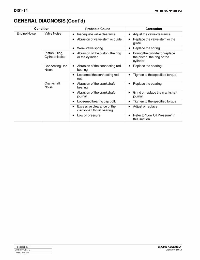
Probable Cause
• Inadequate valve clearance
• Abrasion of valve stem or guide.
• Weak valve spring.
• Abrasion of the piston, the ringor the cylinder.
• Abrasion of the connecting rodbearing.
• Loosened the connecting rodnut.
• Abrasion of the crankshaftbearing.
• Abrasion of the crankshaftjournal.
• Loosened bearing cap bolt.
• Excessive clearance of thecrankshaft thrust bearing.
• Low oil pressure.
Correction
• Adjust the valve clearance.
• Replace the valve stem or theguide.
• Replace the spring.
• Boring the cylinder or replacethe piston, the ring or thecylinder.
• Replace the bearing.
• Tighten to the specified torque
• Replace the bearing.
• Grind or replace the crankshaftjournal.
• Tighten to the specified torque.
• Adjust or replace.
• Refer to “Low Oil Pressure” inthis section.
Condition
GENERAL DIAGNOSIS (Cont’d)
Valve NoiseEngine Noise
Piston, Ring,Cylinder Noise
Connecting RodNoise
CrankshaftNoise

DI01-15
CHANGED BY
EFFECTIVE DATE
AFFECTED VIN
ENGINE ASSEMBLYDI ENG SM - 2004.4
OIL LEAK DIAGNOSISMost fluid oil leaks are easily located and repaired by vi-sually finding the leak and replacing or repairing the nec-essary parts. On some occasions a fluid leak may be dif-ficult to locate or repair. The following procedures mayhelp you in locating and repairing most leaks.
Finding the Leak1. Identify the fluid. Determine whether it is engine oil,
automatic transmission fluid, power steering fluid, etc.
2. Identify where the fluid is leaking from.
2.1 After running the vehicle at normal operatingtemperature, park the vehicle over a large sheetof paper.
2.2 Wait a few minutes.
2.3 You should be able to find the approximatelocation of the leak by the drippings on thepaper.
3. Visually check around the suspected component.Check around all the gasket mating surfaces forleaks. A mirror is useful for finding leaks in areas thatare hard to reach.
4. If the leak still cannot be found, it may be necessaryto clean the suspected area with a degreaser, steamor spray solvent.
4.1 Clean the area well.
4.2 Dry the area.
4.3 Operate the vehicle for several miles at normaloperating temperature and varying speeds.
4.4 After operating the vehicle, visually check thesuspected component.
4.5 If you still cannot locate the leak, try using thepowder or black light and dye method.
Powder Method1. Clean the suspected area.
2. Apply an aerosol-type powder (such as foot powder)to the suspected area.
3. Operate the vehicle under normal operatingconditoins.
4. Visually inspect the suspected component. Youshould be able to trace the leak path over the whitepowder surface to the source.
DIAGNOSTIC INFORMATION AND PROCEDURE
Black Light and Dye MethodA dye and light kit is available for finding leaks, Refer tothe manufacturer's directions when using the kit.
1. Pour the specified amount of dye into the engine oilfill tube.
2. Operate the vehicle normal operating conditions asdirected in the kit.
3. Direct the light toward the suspected area. The dyedfluid will appear as a yellow path leading to thesource.
Repairing the LeakOnce the origin of the leak has been pinpointed and tracedback to its source, the cause of the leak must be deter-mined in order for it to be repaired properly. If a gasket isreplaced, but the sealing flange is bent, the new gasketwill not repair the leak. The bent flange must be repairedalso. Before attempting to repair a leak, check for the fol-lowing conditions and correct them as they may cause aleak.
Gaskets• The fluid level/pressure is too high.
• The crankcase ventilation system is malfunctioning.
• The fasteners are tightened improperly or the threadsare dirty or damaged.
• The flanges or the sealing surface is warped.
• There are scratches, burrs or other damage to thesealing surface.
• The gasket is damaged or worn.
• There is cracking or porosity of the component.
• An improper seal was used (where applicable).
Seals• The fluid level/pressure is too high.
• The crankcase ventilation system is malfunctioning.
• The seal bore is damaged (scratched, burred or nicked).
• The seal is damaged or worn.
• Improper installation is evident.
• There are cracks in the components.
• The shaft surface is scratched, nicked or damaged.
• A loose or worn bearing is causing excess seal wear.

DI01-16
CHANGED BY
EFFECTIVE DATE
AFFECTED VIN
ENGINE ASSEMBLYDI ENG SM - 2004.4
Notice
• Before cranking the engine, make sure that the test wiring, tools and persons are keeping away from movingcomponents of engine (e.g., belt and cooling fan).
• Park the vehicle on the level ground and apply the parking brake.
• Do not allow anybody to be in front of the vehicle.
Specifications
Y220_01005
COMPRESSION PRESSURE TESTThe compression pressure test is to check the conditions of internal components (piston, piston ring, intake andexhaust vale, cylinder head gasket). This test provides current engine operating status.
Compression ratio
Test temperature
Compression pressure Normal value
Minimum value
Permissible pressure difference between individual cylinders
18 : 1
at normal operating temperature (80°C)
32 bar
18 bar
Max. 3 bar

DI01-17
CHANGED BY
EFFECTIVE DATE
AFFECTED VIN
ENGINE ASSEMBLYDI ENG SM - 2004.4
1. Warm the engine up to normal operating temperature(80°C).
2. Disconnect the fuel rail pressure sensor connector tocut off the fuel injection.
3. Place the diagram sheet to compression pressure tester.
Notice
• Disconnect the fuel rail pressure sensor connector to cut off the fuel injection.
• Discharge the combustion residues in the cylinders before testing the compression pressure.
• Apply the parking brake before cranking the engine.
Measuring Procedure
Y220_01006
Y220_01007
Y220_01008
4. Remove the glow plugs and install the compressionpressure tester into the plug hole.
5. Crank the engine for approx. 10 seconds by using thestart motor.
6. Record the test result and measure the compressionpressure of other cylinders with same manner.
7. If the measured value is not within the specifications,perform the cylinder pressure leakage test.
Tightening torque (Tester) 15 Nm

DI01-18
CHANGED BY
EFFECTIVE DATE
AFFECTED VIN
ENGINE ASSEMBLYDI ENG SM - 2004.4
If the measured value of the compression pressure test is notwithin the specifications, perform the cylinder pressure leak-age test.
Permissible Pressure Leakage
Notice
• Perform the pressure in order: 1 - 2 - 3 - 4 - 5
• Do not test the cylinder pressure leakage with wet type test procedure. (do not inject the engine oil into thecombustion chamber)
Y220_01009
Test temperature
At whole engine
At valve and cylinder head gasket
At piston ring
at normal operating temperature (80°C)
Max. 25 %
Max. 10 %
Max. 20 %
CYLINDER PRESSURE LEAKAGE TEST

DI01-19
CHANGED BY
EFFECTIVE DATE
AFFECTED VIN
ENGINE ASSEMBLYDI ENG SM - 2004.4
TIGHTENING TORQUE
Oil nozzle
Main bearing cap
Connecting rod cap
Rear cover
Oil pump
Oil baffle plate assembly
T.G.C.C
Flywheel
Crankshaft hub
Oil pan
High pressure pump assembly
High pressure pump sprocket assembly
High pressure pump bracket
Cylinder head assembly
Camshaft cap
Stud bolt
Camshaft sprocket (Intake)
Camshaft sprocket (Exhaust)
Chain tensioner
Coolant temperature sensor
M6 x 22
M11 x 62
M9 x 52
M6 x 20
M8 x 35SOC
M6 x 20
M6 x 16
M6 x 40
M6 x 60
M6 x 70
M8 x 80SOC
M10 x 30
M18 x 50
M6 x 20
M6 x 35
M6 x 38
M6 x 40
M8 x 40
M14 x 1.5-8-1
M7 x 16
M8 x 25
M8 x 50
M12 x 177
M12 x 158
M8 x 60
M8
M11 x 52
M22
M14
10 ± 1
55 ± 5
90° ± 10°
40 ± 5
90° ± 10°
10 ± 1
25 ± 2.5
10 ± 1
10 ± 1
10 ± 1
10 ± 1
10 ± 1
25 ± 2.5
45 ± 5
90° ± 10°
325 ± 33
90° ± 10°
10 ± 1
10 ± 1
10 ± 1
25 ± 2.5
25 ± 2.5
65 ± 5
20 ± 2 x 90° + 10°
25 ± 2.5
Step1: 20 Nm ± 2 Nm
Step2: 85 Nm ± 5 Nm
Step3: 3 x 90° + 10°
25 ± 2.5
15 ± 1.5
25 ± 2.5
90° ± 10°
65 ± 5
22 ± 2.2
SizeName Tightening TorqueNO.
1
2
3
4
5
6
7
8
9
10
11
12
13
14
15
16
17
18
19
5
12
5
6
3
10
1
6
3
2
1
8
1
24
3
3
4
4
1
3
2
2
11
1
24
10
1
1
1
1
Quantity

DI01-20
CHANGED BY
EFFECTIVE DATE
AFFECTED VIN
ENGINE ASSEMBLYDI ENG SM - 2004.4
Auto tensioner
Water pump assembly
Water pump pulley
Hot water inlet pipe assembly
Alternator bracket
Alternator
Air conditioner compressor assembly
Air conditioner compressor bracket
assembly
Air conditioner compressor sub
bracket assembly
Intake manifold
Bracket
Knock sensor
Camshaft position sensor
Booster pressure sensor
Exhauster manifold
Turbo charger assembly
Turbo charger adaptor piece
Nut
Combination bolt
T/C oil supply pipe
T/C oil return pipe
EGR valve assembly
EGR-LH pipe bolt
EGR combination bolt
EGR-RH pipe nut
Glow plug cable nut
Vacuum pump
Cooling fan bracket assembly
Cylinder head cover
M8 x 45(LOWER)
M12 x 90
M6 x 50
M6 x 12
M6 x 12
M8 x 32
M10 x 90
M8 x 95
M8 x 25
M8 x 60
M6 x 14
M8 x 16
M8 x 45
M8 x 130
M6 x 16
M8 x 28
M8 x 16
M6 x 16
M8
M8
M8
M8 x 22
M6 x 16 (Cylinder block side)
M16 (T/C side)
M6 x 16 (T/C side)
M6 x 16 (Cylinder block side)
M8 x 22
M6 x 16
M8 x 22
M6 x 16
M8 x 16
M8
M5
M6 x 20
M6 x 25
M6 x 65
M6 x 85
M6 x 35
SizeNameNO.
20
21
22
23
24
25
26
27
28
29
30
31
32
33
34
35
36
37
38
39
40
41
42
43
44
45
46
47
32 ± 3
82 ± 6
10 ± 1
10 ± 1
10 ± 1
25 ± 2.5
46 ± 4.6
46 ± 4.6
25 ± 2.5
25 ± 2.5
10 ± 1.0
25 ± 2.5
25 ± 2.5
25 ± 2.5
10 ± 1.0
20 ± 2.6
12 ± 1.7
10 ± 1.0
40 ± 4
25 ± 2.5
32 ± 3.2
25 ± 2.5
25 ± 2.5
25 ± 2.5
20 ± 2.0
10 ± 1.0
10 ± 1.0
25 ± 2.5
10 ± 1.0
35 ± 2.0
10 ± 1.0
25 ± 2.5
35 ± 2.0
15 ± 3
10 ± 1.0
10 ± 1.0
10 ± 1.0
10 ± 1.0
23 ± 2.3
Tightening Torque
1
1
7
4
2
4
2
4
1
3
1
1
6
6
1
2
1
2
10
4
1
1
1
1
1
2
2
2
2
2
4
4
2
5
3
5
1
3
21
Quantity

DI01-21
CHANGED BY
EFFECTIVE DATE
AFFECTED VIN
ENGINE ASSEMBLYDI ENG SM - 2004.4
Vacuum modulator
WDT combination bolt
Oil dipstick tube
Oil filter assembly
Fuel rail assembly
Injector clamp washer
Fuel pipe clip (H-C)
Fuel pipe clip (C-I)
Crankshaft position sensor
Crankshaft position sensor
Fuel pressure sensor
Wiring
Intake manifold bracket
Power steering pump
Piston protrusion
Clearance between connecting rod
and pin boss
End play of crankshaft
NameNO.
48
49
50
51
52
53
54
55
56
57
58
59
60
61
62
63
64 NEW: 0.100 ~ 0.245 mm // USED: 0.300 mm
10 ± 1.0
10 ± 1.0
10 ± 1.0
25 ± 2.5
25 ± 2.5
25 ± 2.5
25 ± 2.5
10 ± 1.0
180 + 20°
10 ± 1.0
10 ± 1.0
0.8 ± 0.4
0.7 ~ 1.5
10 ± 1.0
25 ± 2.5
25 ± 2.5
25 ± 2.5
25 ± 2.5
0.765 ~ 1.055
0.05 ~ 0.31
Tightening Torque
4
3
1
1
2
1
3
5
1
5
1
1
5
2
2
2
2
5
5
Quantity
M6 x 16SOC
M6 x 16
M6 x 16
M8 x 35SOC
M8 x 50SOC
M8 x 55SOC
M8 x 35SOC
M6 x 60
M6 x 19
M6 x 16
M5 x 17
GAP
M6 x 16
M8 x 16
M8 x 40
M8 x 100
NUT
Size

DI01-22
CHANGED BY
EFFECTIVE DATE
AFFECTED VIN
ENGINE ASSEMBLYDI ENG SM - 2004.4
ENGINE MOUNTING
Y220_01010
Notice
1. Disconnect the negative battery cable before removal.
2. Drain the engine oil.
3. Drain the engine coolant.
4. Be careful not to splash the fuel to the vehicle body. It may cause a fire or vulcanization of rubber products.Make sure to block the fuel related hoses before removal.
1. Side Mountings
Left
Right
2. Transmission Mounting
3. Exhaust Manifold and Pipe 4. Cables and Connectors
REMOVAL AND INSTALLATION

DI01-23
CHANGED BY
EFFECTIVE DATE
AFFECTED VIN
ENGINE ASSEMBLYDI ENG SM - 2004.4
1. Disconnect the negative battery cable.
2. Remove the engine hood assembly.
Note
Refer to “Body” section.
Engine Assembly - Removal
3. Remove the skid plate under the engine compartment.
Installaiton Notice
4. Loosen the radiator drain cock and drain the coolant.
Y220_01012
Y220_01013
Y220_01014
Notice
If not necessary, place the ignition switch at “OFF”position.
Tightening torque 12 ± 1.2 Nm
Notice
1. Be careful not to contact with coolant. If contacted,wash with soap and water to ensure all coolant isremoved.
2. Use only designated coolant.
3. Open the coolant reservoir cap to help thedraining.
Y220_01011

DI01-24
CHANGED BY
EFFECTIVE DATE
AFFECTED VIN
ENGINE ASSEMBLYDI ENG SM - 2004.4
5. Loosen the cylinder block drain plug (under the intakemanifold) and drain the coolant completely.
6. Retighten the drain plug with the specified tighteningtorque.
7. Remove the inlet hose (1) and the heater hose (2) underthe radiator.
8. Remove the coolant outlet hose over the radiator.
9. Remove the radiator grille and loosen the hose clamp onthe outlet port of turbo intercooler.
Note
For the removal and installation of radiator grille,refer to “Cooling System” section.
Y220_01015
Y220_01016
Y220_01017
Y220_01021
Notice
Be careful not to damage the rubber hose.
Notice
Be careful not to damage the rubber hose.
Tightening torque 30 Nm

DI01-25
CHANGED BY
EFFECTIVE DATE
AFFECTED VIN
ENGINE ASSEMBLYDI ENG SM - 2004.4
14. Loosen the clamp on the inlet hose of intercooler.
13. Loosen the clamps and remove the intake air hose fromthe turbo charger.
10. Loosen the hose clamp on intake air hose of turbo chargerand remove the intake air hose.
11. Separate the outlet hose of oil separator from the intakeair hose of turbo charger.
12. Loosen the clamp on the intake air duct hose of turbocharger at the air cleaner side and separate the hosefrom the air cleaner housing.
Y220_01022
Y220_01018
Y220_01020
Y220_01023

DI01-26
CHANGED BY
EFFECTIVE DATE
AFFECTED VIN
ENGINE ASSEMBLYDI ENG SM - 2004.4
15. Loosen the clamp on the intake manifold and remove theintake air hose.
16. Remove the exhaust pipe mounting nuts from the turbocharger.
Installation Notice
17. Remove the power steering inlet pipe and the outlet hosefrom the power steering pump.
18. Remove the vacuum hose from the brake booster.
Installation Notice
Notice
Plug the openings of hoses and pump with caps notto flow out the oil.
Tightening torque 25 ± 2.5 Nm
Installation Notice
Inlet pipe union nut 25 ± 2.5 Nm
Vacuum pipe union nut
(at vacuum pump side)10 Nm
Y220_01024
Y220_01027
Y220_01028
Y220_01029

DI01-27
CHANGED BY
EFFECTIVE DATE
AFFECTED VIN
ENGINE ASSEMBLYDI ENG SM - 2004.4
23. Disconnect the “ST” terminal and “+” terminal cables fromthe starter motor.
20. Remove the engine oil heater outlet hose.
21. Disconnect the cables from the cylinder block and othercomponents.
(e.g., coolant temperature sensor cable and oiltemperature switch)
22. Disconnect the engine ground cable and the alternator“+” terminal cable.
19. Remove the supply inlet, supply outlet and return hosefrom the fuel filter.
Y220_01030
Y220_01031
Y220_01032
Y220_01033
Notice
1. When separating the hoses from the fuel filter,plug the openings with caps so that thecontaminants will not get into the fuel system.
2. Mark on all the hoses not to be mixed each other.
Notice
Make sure to properly tighten the cable nuts wheninstalling. Otherwise, it may cause a poor ground orelectric charging problem.
Notice
Make sure to properly tighten the cable nuts wheninstalling. Otherwise, it may cause an engine startingproblem.

DI01-28
CHANGED BY
EFFECTIVE DATE
AFFECTED VIN
ENGINE ASSEMBLYDI ENG SM - 2004.4
24. Disconnect the air conditioner compressor connector andremove the inlet and outlet pipes from the compressor.
25. For the automatic transmission equipped vehicle, removethe oil cooler pipes.
Note
The oil cooler pipes are connected to cylinder blockat both sides and bottom area of oil with brackets.
Installation Notice
26. Set up the special to the cooling fan pulley and removethe cooling fan assembly. To make the removal easier,loosen the radiator shroud.
Installation Notice
Y220_01034
Y220_01035
Y220_01036
Y220_01038
Cooling fan pulley bolt 10 ± 1.0 Nm
Pipe mounting bracket bolt
Pipe hose (radiator side)union nut
25 ± 2.5 Nm
25 ± 2.5 Nm

DI01-29
CHANGED BY
EFFECTIVE DATE
AFFECTED VIN
ENGINE ASSEMBLYDI ENG SM - 2004.4
Y220_01040
27. Remove the radiator shroud.
Installation Notice
28. Take off the fan belt from the engine.
Note
1. Insert a tool into the belt tensioner and rotate itcounterclockwise to take off the fan belt.
2. After installation of the fan belt, pump the belttensioner 3 to 4 times.
Y220_01039
Tightening torque 10 ± 1.0 Nm
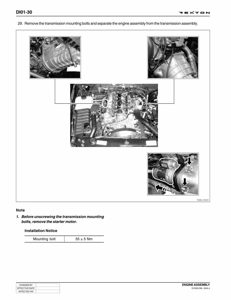
DI01-30
CHANGED BY
EFFECTIVE DATE
AFFECTED VIN
ENGINE ASSEMBLYDI ENG SM - 2004.4
Y220_01041
29. Remove the transmission mounting bolts and separate the engine assembly from the transmission assembly.
Note
1. Before unscrewing the transmission mountingbolts, remove the starter motor.
Mounting bolt 55 ± 5 Nm
Installation Notice

DI01-31
CHANGED BY
EFFECTIVE DATE
AFFECTED VIN
ENGINE ASSEMBLYDI ENG SM - 2004.4
Y220_01042
30. Remove the engine assembly mounting nuts at both sides.
Installation Notice
Mounting Nut 55 ± 5 Nm
32. Put the removed engine assembly on the safety stand.
Y220_01043
31. Hook the chain on the engine brackets and carefullypull out the engine assembly from the vehicle by usinga hoist or crane.

DI01-32
CHANGED BY
EFFECTIVE DATE
AFFECTED VIN
ENGINE ASSEMBLYDI ENG SM - 2004.4
COMPONENTS AND SPECIAL TOOLS
Y220_01044
Injector puller
Injector copper washerpuller
Valve remover/installer Pulley lock/wrench HP pump lock HP pump bearing puller
Fuel pipe wrench Sealing capsGlow plug puller
Engine lock
DISASSEMBLY AND REASSEMBLY

DI01-33
CHANGED BY
EFFECTIVE DATE
AFFECTED VIN
ENGINE ASSEMBLYDI ENG SM - 2004.4
Preparations and Preceding Works1. Remove the cylinder block drain plug and seal and
completely drain the residual coolant from the cylinderblock.
Inspection Before Disassembly andReassembly
4. Loosen the oil drain plug and completely drain the engineoil.
Y220_01045
Y220_01046
Y220_01047
Notice
Replace the seal with new one once removed.
2. When the fan belt is installed, gently pump the belt shockabsorber mounting bolt (M19) 3 times.
3. Take off the fan belt while pushing the mounting bolt (M19).
Drain plug 25 ± 2.5 Nm
Tightening torque 30 Nm

DI01-34
CHANGED BY
EFFECTIVE DATE
AFFECTED VIN
ENGINE ASSEMBLYDI ENG SM - 2004.4
Y220_01048
Accessories - Removal and Installation
PCV valve and oil separator EGR valve pipe (LH, Center, RH)
Power steering pump
Cooling fan clutch
Auto tensioner
Alternator
Turbo charger
Fuel return hose
Cable and connector
Oil filter assembly
EGR valve
Start motor
Mounting bracket
Air conditioner compressor

DI01-35
CHANGED BY
EFFECTIVE DATE
AFFECTED VIN
ENGINE ASSEMBLYDI ENG SM - 2004.4
• The engine accessories can be removed without any specific order. In general, remove the components from topto bottom. However, be careful not to splash the lubricants to engine and body when disassembly. Especially,avoid getting into other components.
Removal and Installation Order of Major Accessories
1. Vacuum Modulator
2. Engine Cables and Connectors
3. Fuel Hoses
3-1. EGR Valve Assembly
4. Oil Filter Assembly
4-1. Belt Tensioning Assembly
5. Power Steering Pump Assembly
6. Air Conditioner Compressor Assembly
7. PCV Valve Assembly
8. Turbo Charger
Oil Dipstick Tube
Alternator Assembly
+
* Camshaft Position Sensor
* Crankshaft Position Sensor
* Injector Fuel Line Connector
* Glow Plug Connector
* Fuel Return Hose
* High/Low Pressure Hoses in HP Pump
* Ground Cables
* Fuel Pressure Sensor Connector
* Booster Pressure Sensor Connector
* Knock Sensor Connector
* Coolant Temperature Sensor Connector
* HP Pump: Fuel Temperature Sensor (Green)
IMV (Brown)

DI01-36
CHANGED BY
EFFECTIVE DATE
AFFECTED VIN
ENGINE ASSEMBLYDI ENG SM - 2004.4
1. Remove the fuel pipes.
A. Remove the fuel supply pipes between eachcylinder and common rail with a special tool.
Installation Notice
B. Remove the high fuel pressure pipe mounting boltswith a special tool.
- High fuel pressure supply pipe at common railside
Installation Notice
Y220_01049
Y220_01050
Y220_01051
Y220_01052
Notice
1. Plug the openings of injector nozzle and commonrail with sealing caps after removed the fuel pipes.
Tightening torque 40 ± 4.0 Nm
2. Replace the pipes with new ones. Be careful notto be mixed the fuel pipes because the pipeappearance of #1 and #3 cylinders and #2 and #4are same each other.
Tightening torque 40 ± 4 Nm
No. 1 No. 3 No. 2 No. 4 No. 5

DI01-37
CHANGED BY
EFFECTIVE DATE
AFFECTED VIN
ENGINE ASSEMBLYDI ENG SM - 2004.4
Y220_01055
C. High fuel pressure supply pipe at HP pump side
Installation Notice
D. Unscrew the bracket mounting bolts and remove thehigh fuel pressure supply pipes.
Note
Special tool: Fuel pipe remover and installer
Tightening torque 40 ± 4.0 Nm
Y220_01054
Y220_01053
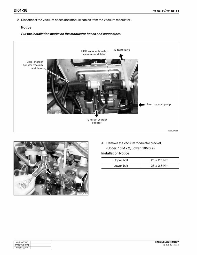
DI01-38
CHANGED BY
EFFECTIVE DATE
AFFECTED VIN
ENGINE ASSEMBLYDI ENG SM - 2004.4
Turbo chargerbooster vacuum
modulator
EGR vacuum boostervacuum modulator
To EGR valve
From vacuum pump
To turbo chargerbooster
Y220_01057
2. Disconnect the vacuum hoses and module cables from the vacuum modulator.
Y220_01056
A. Remove the vacuum modulator bracket.
(Upper: 10 M x 2, Lower: 10M x 2)
Installation Notice
Upper bolt
Lower bolt
25 ± 2.5 Nm
25 ± 2.5 Nm
Notice
Put the installation marks on the modulator hoses and connectors.

DI01-39
CHANGED BY
EFFECTIVE DATE
AFFECTED VIN
ENGINE ASSEMBLYDI ENG SM - 2004.4
Y220_01058
3. Disconnect the wiring harnesses and connectors from the engine.
Fuel return hose Injector fuel lineconnector
Glow plug connector
Camshaft positionsensor
Crankshaft positionsensor
Oil pressure switchHP pump connector
Knock sensor connectorCoolant temperature
sensor connectorBooster pressure sensor
connectorFuel pressure sensor
connector
Fuel temperatureSensor
IMV

DI01-40
CHANGED BY
EFFECTIVE DATE
AFFECTED VIN
ENGINE ASSEMBLYDI ENG SM - 2004.4
A. Remove the cable assembly from the engine.
Important
1. If possible, remove the cables after removing thefuel pipes. It make the operation easier and protectthe cables and connectors.
2. Remove the cable screws and ground cable, andthen remove the engine cable assembly.
4. Disconnect the high and low fuel pressure hoses fromthe HP pump.
Notice
• Be careful not to damage the HP pump connectingpipe (venturi) while removing the fuel hose fromthe HP pump.
Notice
• Be careful not to damage the hose connections.
• Plug the openings in HP pump immediately afterdisconnecting the hoses.
Y220_01059
Y220_01060
Y220_01061

DI01-41
CHANGED BY
EFFECTIVE DATE
AFFECTED VIN
ENGINE ASSEMBLYDI ENG SM - 2004.4
5. Remove the EGR valve and EGR valve pipe.
A. Disconnect the vacuum hose from the EGR valve.
B. Unscrew the EGR valve bolts and EGR #1 pipeconnecting bolts and remove the EGR valve and steelgasket.
Installation Notice
C. Remove the EGR valve #1 pipe.
Installation Notice
D. Unscrew the EGR valve #3 pipe (2) mounting boltsand remove the pipe from the exhaust manifold.
Installation Notice
Notice
The EGR #2 pipe should be replaced with new one.
EGR valve bolt
EGR valve and
center pipe bolt
25 ± 2.5 Nm
25 ± 2.5 Nm
Center pipe bolt
Center pipe and #1 pipe
bolt and nut
35 ± 3.5 Nm
35 ± 3.5 Nm
Tightening torque 35 ± 3.5 Nm
Notice
1. The EGR #3 pipe should be replaced with newone.
2. Make sure that the convex surface of new steelgasket is facing to the bolts.
6. Remove the oil filter assembly.
A. Remove the oil cooler hose.
Y220_01062
Y220_01063
2
Y220_01064
Y220_01065

DI01-42
CHANGED BY
EFFECTIVE DATE
AFFECTED VIN
ENGINE ASSEMBLYDI ENG SM - 2004.4
B. Remove the oil filter assembly mounting bolts.
C. Remove the oil filter assembly from the cylinder block.
Installation Notice
- Replace the oil filter gasket with new one.
7. Remove the belt tensioning device.
A. Remove the shock absorber lower mounting bolt.
Installation Notice
B. Remove the shock absorber upper mounting bolt.
Installation Notice
Y220_01066
Y220_01067
Y220_01068
Y220_01069
Notice
Be careful not to flow out the residual oil from theengine. If flown out, immediately wipe it out.
Tightening torque 25 ± 2.5 Nm
Tightening torque 32 ± 3 Nm
Tightening torque 82 ± 6 Nm

DI01-43
CHANGED BY
EFFECTIVE DATE
AFFECTED VIN
ENGINE ASSEMBLYDI ENG SM - 2004.4
B. Remove the power steering pump assembly from theengine.
8. Remove the air conditioner compressor assembly.
A. Unscrew the bolts and remove the air conditionercompressor assembly.
Installation Notice
C. Remove the belt tensioning device.
7. Remove the power steering pump assembly.
A. Remove the power steering pump mounting bolts.
Installation Notice
Y220_01070
Y220_01071
Y220_01072
Y220_01073
Notice
• To prevent the oil leaks, store the removed shockabsorber assembly with standing up.
• For air bleeding, pump the shock absorber around3 times after installation.
• Be careful not to damage the rubber parts of theshock absorber when removing.
• To prevent the oil leaks, remove the bolts from bottomto top section. On the contrary, when installing,tighten the bolts from top to bottom section.
Tightening torque 25 ± 2.5 Nm
Notice
Be careful not to flow out the oil.
Notice
To prevent the oil leaks, store the removed powersteering pump assembly with standing up.
Tightening torque 25 ± 2.5 Nm

DI01-44
CHANGED BY
EFFECTIVE DATE
AFFECTED VIN
ENGINE ASSEMBLYDI ENG SM - 2004.4
9. Remove the PCV valve assembly.
A. Remove the PCV valve hose.
B. Unscrew the bolts and remove the air conditionermounting bracket.
Installation Notice
Y220_01074
Y220_01075
Y220_01076
Y220_01077
Front bolt
Side bolt
25 ± 2.5 Nm
25 ± 2.5 Nm
B. Remove the PCV valve hose connected to the engineoil hose.
C. Unscrew the PCV valve mounting bolts and removethe PCV valve assembly.
Installation Notice
Tightening torque 10 ± 1.0 Nm

DI01-45
CHANGED BY
EFFECTIVE DATE
AFFECTED VIN
ENGINE ASSEMBLYDI ENG SM - 2004.4
10. Remove the oil dipstick tube assembly.
Unscrew the bracket bolts and remove the dipstick tubewith O-ring.
Installation Notice
Insert new O-ring into the oil dipstick tube beforeinstallation.
Tightening torque 10 ± 1.0 Nm
Installation Notice
11. Remove the turbo charger assembly.
A. Unscrew the bolts and remove the oil supply pipe.
Installation Notice
B. Unscrew the bolts and remove the oil return pipe.
Installation Notice
• Make sure to install the gasket with correct direction.
Y220_01078
Y220_01079
Y220_01080
Y220_01081
Upper bolt (M19)
Lower bolt (M17)
25 ± 2.5 Nm
20 ± 2.0 Nm
Tightening torque 10 ± 1.0 Nm

DI01-46
CHANGED BY
EFFECTIVE DATE
AFFECTED VIN
ENGINE ASSEMBLYDI ENG SM - 2004.4
C. Unscrew the turbo charger mounting bracket bolts.
Installation Notice
D. Unscrew the turbo charger mounting bolts to exhaustmanifold.
E. Remove the turbo charger assembly.
Installation Notice
Tightening torque 25 ± 2.5 Nm
12. Remove the alternator assembly.
A. Unscrew the bolts and remove the alternator.
Note
Alternator Capacity: 140 A
Installation Notice
Y220_01082
Y220_01083
Y220_01084
Y220_01085
Tightening torque 25 ± 2.5 Nm
Notice
Use only 12 1/2 wrench.
Tightening torque 46 ± 4.6 Nm

DI01-47
CHANGED BY
EFFECTIVE DATE
AFFECTED VIN
ENGINE ASSEMBLYDI ENG SM - 2004.4
B. Remove the alternator mounting bracket.
Installation Notice
Y220_01086
M13 bolt
Torx 6 bolt
25 ± 2.5 Nm
25 ± 2.5 Nm

DI01-48
CHANGED BY
EFFECTIVE DATE
AFFECTED VIN
ENGINE ASSEMBLYDI ENG SM - 2004.4
2. Remove the injectors with a injector extractor (specialtool).
1. Unscrew the injector nozzle holder bolts (12-sided) andremove the injector bracket.
Installation Notice
3. If the copper washer is in injector hole, remove it with aspecial tool as shown in the figure.
Engine - Disassembly and Reassembly
Y220_01089
Y220_01090
Y220_01092
Notice
• Be careful not to take off the sealing caps on theinjectors and fuel system.
• Replace the copper washers with new ones wheninstalling.
Tightening torque9 ± 1.0 Nm,
190° + 10°

DI01-49
CHANGED BY
EFFECTIVE DATE
AFFECTED VIN
ENGINE ASSEMBLYDI ENG SM - 2004.4
4. Remove the glow plugs with a special tool.
Installation Notice
5. Unscrew the Torx bolts and remove the common rail fromthe engine.
Installation Notice
6. Remove the booster sensor from the engine.
Installation Notice
7. Unscrew the bolt and remove the camshaft positionsensor.
Installation Notice
Y220_01091
Y220_01087
Y220_01088
Y220_01093
Tightening torque 15 ± 3 Nm
Tightening torque 25 ± 2.5 Nm
Notice
Plug the openings with sealing cap.
Tightening torque 10 ± 1.0 Nm
Tightening torque 12 ± 1.7 Nm
• Apply Loctite on the thread before installation.

DI01-50
CHANGED BY
EFFECTIVE DATE
AFFECTED VIN
ENGINE ASSEMBLYDI ENG SM - 2004.4
8. Unscrew the bolts and remove the cooling fan pulley whileholding it with a special tool.
10. Unscrew the bolts and remove the cooling fan bracketassembly (timing chain cover).
11. Unscrew the bolts and remove the cylinder head cover.
9. Remove the cooling fan belt idle pulley while holding itwith a special tool.
Y220_01094
Y220_01095
Y220_01096
Y220_01097
Tightening torque 10 ± 1.0 Nm
Tightening torque 10 ± 1.0 Nm
Tightening torque 10 ± 1.0 Nm
Tightening torque 10 ± 1.0 Nm
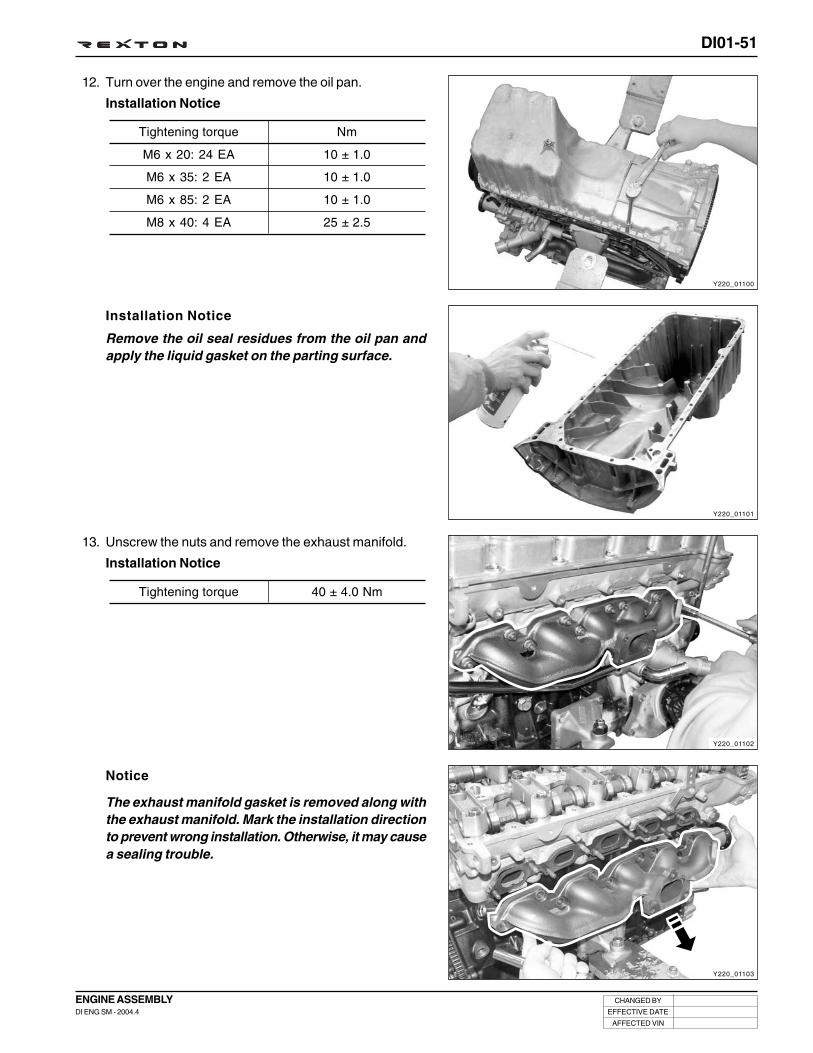
DI01-51
CHANGED BY
EFFECTIVE DATE
AFFECTED VIN
ENGINE ASSEMBLYDI ENG SM - 2004.4
13. Unscrew the nuts and remove the exhaust manifold.
Installation Notice
12. Turn over the engine and remove the oil pan.
Installation Notice
Installation Notice
Remove the oil seal residues from the oil pan andapply the liquid gasket on the parting surface.
Tightening torque
M6 x 20: 24 EA
M6 x 35: 2 EA
M6 x 85: 2 EA
M8 x 40: 4 EA
Nm
10 ± 1.0
10 ± 1.0
10 ± 1.0
25 ± 2.5
Y220_01100
Y220_01101
Y220_01102
Y220_01103
Tightening torque 40 ± 4.0 Nm
Notice
The exhaust manifold gasket is removed along withthe exhaust manifold. Mark the installation directionto prevent wrong installation. Otherwise, it may causea sealing trouble.

DI01-52
CHANGED BY
EFFECTIVE DATE
AFFECTED VIN
ENGINE ASSEMBLYDI ENG SM - 2004.4
14. Unscrew the bolts and remove the thermostat.
Installation Notice
15. Unscrew the bolts and remove the water pump.
Installation Notice
16. Unscrew the bolts and remove the water pump housing.
Installation Notice
17. Unscrew the bolts and remove the coolant inlet port fromthe intake manifold.
Installation Notice
Y220_01104
Y220_01105
Y220_01106
Y220_01107
Tightening torque 10 ± 1.0 Nm
Notice
Be careful not to flow out the residual coolant.
Tightening torque 10 ± 1.0 Nm
Tightening torque 10 ± 1.0 Nm
Tightening torque 25 ± 2.5 Nm
Notice
Be careful not to flow out the residual coolant.
Notice
Be careful not to get the coolant into the intakemanifold and engine.

DI01-53
CHANGED BY
EFFECTIVE DATE
AFFECTED VIN
ENGINE ASSEMBLYDI ENG SM - 2004.4
18. Unscrew the bolts and remove the intake manifoldassembly.
Installation Notice
19. Remove the vacuum pump from the cylinder head.
Installation Notice
20. Install the engine lock (special tool) onto the flywheelring gear so that the engine will not rotate.
Y220_01108
Y220_01109
Y220_01110
Y220_01111
Notice
Replace the gasket with new one once removed.
Tightening torque 25 ± 2.5 Nm
Tightening torque 10 ± 1.0 Nm

DI01-54
CHANGED BY
EFFECTIVE DATE
AFFECTED VIN
ENGINE ASSEMBLYDI ENG SM - 2004.4
22. Pull out the lock pin and remove the upper chain guidebracket.
23. Unscrew the bolt and remove the intake camshaftsprocket.
Installation Notice
24. Unscrew the bolt and remove the exhaust camshaftsprocket.
Installation Notice
21. Remove the chain tensioner.
Preceding works: removal of EGR pipe and oil dipsticktube
Tightening torque25 ± 2.5 Nm,
90° + 10°
Tightening torque25 ± 2.5 Nm,
90° + 10°
Tightening torque 65 ± 5.0 Nm
Y220_01114
Y220_01113
Y220_01112
Y220_01119

DI01-55
CHANGED BY
EFFECTIVE DATE
AFFECTED VIN
ENGINE ASSEMBLYDI ENG SM - 2004.4
25. Remove the camshaft bearing cap bolts so that thetightening force can be relieved evenly.
• Intake: #1, #3, #6
• Exhaust: #7, #9, #12
* However, there is no specific removal sequence.
• Intake: #2, #4, #5
• Exhaust: #8, #10, #11
* Do not remove the bolts at a time completely. Removethem step by step evenly or camshaft can be seriouslydamaged.
Installation Notice
27. Remove the finger follower and the HLA device.
26. Remove the intake and exhaust camshafts from thecylinder head.
Tightening torque 25 ± 2.5 Nm
Notice
• Avoid contact with hot metal parts when removingthe HLA device immediately after stopping theengine.
• Be careful not to be contaminated by foreignmaterials.
• To prevent the oil leaks, store the removed fingerfollower and HLA device with standing up.
• If the HLA can be easily pressed in by hand, itindicates the oil inside of HLA has been flown out.In this case, replace it with new one.
Y220_01115
Exhaust
Y220_01118
Y220_01117
Y220_01116
Intake

DI01-56
CHANGED BY
EFFECTIVE DATE
AFFECTED VIN
ENGINE ASSEMBLYDI ENG SM - 2004.4
29. Remove the cylinder head bolts according to thenumerical sequence.
Installation Notice
31. Remove the cylinder head.
30. Measure the length of cylinder head bolts.
• If the maximum length is exceeded by 2 mm, replacethe cylinder head bolt.
28. Pull out the pin and remove the timing chain guide fromthe engine.
Tightening torque
M8 x 25: 2 EA
M8 x 50: 2 EA
M12 x 177: 11 EA
M12 x 158: 1 EA
(Vacuum pump side)
Nm
25 ± 2.5
25 ± 2.5
85 ± 5 Nm,
3 x 90° + 10°
Length when new
177 mm
158 mm
Maximum Limit
179 mm
160 mm
Notice
• Inspect the cylinder head surface.
• Store the removed injectors and glow plugs so thatthey will not be damaged.
Y220_01120
Y220_01121
Y220_01122
Y220_01123

DI01-57
CHANGED BY
EFFECTIVE DATE
AFFECTED VIN
ENGINE ASSEMBLYDI ENG SM - 2004.4
32. Measure the piston protrusion from the parting surface.
• Specified Value: 0.765 ~ 1.055 mm
33. Remove the cylinder head gasket.
Installation Notice
• Replace the cylinder head gasket with new one.Make sure to place the “TOP” mark upward.
1. Put the steel gasket on the cylinder block andposition the cylinder head.
34. Turn over the engine and remove the baffle plate.
Installation Notice
Tightening torque 10 ± 1.0 Nm
Tightening torque
Step 1 20 ± 2.0 Nm
Step 2 85 ± 5.0 Nm
Step 3 90 ± (3 times) + 10°
• Apply the oil on the bolt thread when installing.
• Always insert new washer first.
• The bolts (12) at vacuum pump side are shorterthan others.
Y220_01124
Y220_01125
Y220_01127
Y220_01126
2. Tighten the cylinder head bolts to specified torqueand torque angle.

DI01-58
CHANGED BY
EFFECTIVE DATE
AFFECTED VIN
ENGINE ASSEMBLYDI ENG SM - 2004.4
36. Remove the piston assembly from the cylinder block.
A. Unscrew the bearing cap bolts.
Installation Notice
* Tighten the bolts from #1 cap.
C. Remove the piston assembly through the cylinder.
Installation Notice
* Align the oil grooves in bearing cap and connectingrod.
B. Remove the bearing caps and lower bearing shells.
Y220_01128
Y220_01129
Y220_01130
Y220_01131
Tightening torque 25 ± 2.5 Nm
35. Unscrew the bolts and remove the oil strainer assembly.
Installation Notice
Step 1
Step 2
55 ± 5.0 Nm
90° + 10°
Notice
Do not mix up upper and lower crankshaft bearingshells.

DI01-59
CHANGED BY
EFFECTIVE DATE
AFFECTED VIN
ENGINE ASSEMBLYDI ENG SM - 2004.4
D. Remove the snap ring piston pin from the piston.
E. Disassemble the piston and connecting rod.
F. Remove the piston rings from the piston.
Installation Notice
Replace the piston ring, bearing and snap ring withnew ones.
37. Lock the flywheel and remove the center bolt andcrankshaft pulley.
Installation Notice
38. Remove the timing chain cover assembly.
A. Remove the cover bolts.
Installation Notice
B. Hold the timing chain and remove the timing chaincover by tapping it with a rubber hammer and ascrewdriver.
Installation Notice
Apply the sealant on the parting surface.
Y220_01132
Y220_01133
Y220_01134
Y220_01135
Tightening torque325 ± 33 Nm,
90° + 10°
Tightening torque 10 ± 1.0 Nm

DI01-60
CHANGED BY
EFFECTIVE DATE
AFFECTED VIN
ENGINE ASSEMBLYDI ENG SM - 2004.4
39. Remove the timing chain guide rail and timing chain.
• Remove the HP pump assembly.
41. Remove the crankshaft sprocket with a special tool.
Y220_01136
Y220_01138
Y220_01139
Y220_01137
40. Remove the HP pump bolts and the HP pump bracketbolts.

DI01-61
CHANGED BY
EFFECTIVE DATE
AFFECTED VIN
ENGINE ASSEMBLYDI ENG SM - 2004.4
Y220_01141
Y220_01140
Note
• Install in the reverse order of removal.
• Tighten the fasteners with the specified tightening torques.
• Replace the gaskets and bearings with new ones.
• Make sure to install the gaskets in correct direction.
42. Remove the flywheel and the crankshaft strainer.
Installation Notice
43. Unscrew the bolts and remove the crankshaft bearingcaps.
Installation Notice
Tightening torque45 ± 5.0 Nm,
90° + 10°
Tightening torque55 ± 5.0 Nm,
90° + 10°
Notice
• Remove the bearing cap bolts from inside to outsidewith a pair.
• Do not mix up the crankshaft bearing caps andshells.

MEMO
.............................................................................................................................................................................................................................................................................................................................................................................................................................................................................
.............................................................................................................................................................................................................................................................................................................................................................................................................................................................................
.............................................................................................................................................................................................................................................................................................................................................................................................................................................................................
.............................................................................................................................................................................................................................................................................................................................................................................................................................................................................
.............................................................................................................................................................................................................................................................................................................................................................................................................................................................................
.............................................................................................................................................................................................................................................................................................................................................................................................................................................................................
.............................................................................................................................................................................................................................................................................................................................................................................................................................................................................
.............................................................................................................................................................................................................................................................................................................................................................................................................................................................................
.............................................................................................................................................................................................................................................................................................................................................................................................................................................................................
.............................................................................................................................................................................................................................................................................................................................................................................................................................................................................
.............................................................................................................................................................................................................................................................................................................................................................................................................................................................................
.............................................................................................................................................................................................................................................................................................................................................................................................................................................................................
.............................................................................................................................................................................................................................................................................................................................................................................................................................................................................
.............................................................................................................................................................................................................................................................................................................................................................................................................................................................................
.............................................................................................................................................................................................................................................................................................................................................................................................................................................................................
.............................................................................................................................................................................................................................................................................................................................................................................................................................................................................
.............................................................................................................................................................................................................................................................................................................................................................................................................................................................................
.............................................................................................................................................................................................................................................................................................................................................................................................................................................................................
.............................................................................................................................................................................................................................................................................................................................................................................................................................................................................
.............................................................................................................................................................................................................................................................................................................................................................................................................................................................................
.............................................................................................................................................................................................................................................................................................................................................................................................................................................................................
.............................................................................................................................................................................................................................................................................................................................................................................................................................................................................
.............................................................................................................................................................................................................................................................................................................................................................................................................................................................................
.............................................................................................................................................................................................................................................................................................................................................................................................................................................................................
.............................................................................................................................................................................................................................................................................................................................................................................................................................................................................
.............................................................................................................................................................................................................................................................................................................................................................................................................................................................................
.............................................................................................................................................................................................................................................................................................................................................................................................................................................................................
.............................................................................................................................................................................................................................................................................................................................................................................................................................................................................
.............................................................................................................................................................................................................................................................................................................................................................................................................................................................................

ENGINE HOUSING
SECTION DI02

DI02-1
CHANGED BY
EFFECTIVE DATE
AFFECTED VIN
ENGINE HOUSINGDI ENG SM - 2004.4
ENGINE HOUSING
00SECTION DI02
Table of Contents
CYLINDER HEAD/CYLINDER BLOCK ....................... DI02-3
Cylinder head.......................................................... DI02-3
Camshaft assembly .............................................. DI02-17
Timing chain assembly .......................................... DI02-25
Cylinder block ....................................................... DI02-29
CRANKSHAFT ........................................................... DI02-32
Arrangement of thrust washers and bearings ...... DI02-33
Torsional vibration damper ................................... DI02-38
FLYWHEEL ................................................................DI02-42
Dual mass flywheel (DMF, Manual transmissionequipped vehicle) ................................................. DI02-42
PISTON AND CONNECTING ROD............................ DI02-44
Piston ring ............................................................. DI02-45
Cylinder inner diameter and piston size ............... DI02-46
HIGH PRESSURE PUMP (HPP) ............................... DI02-51
Components locator ............................................. DI02-51

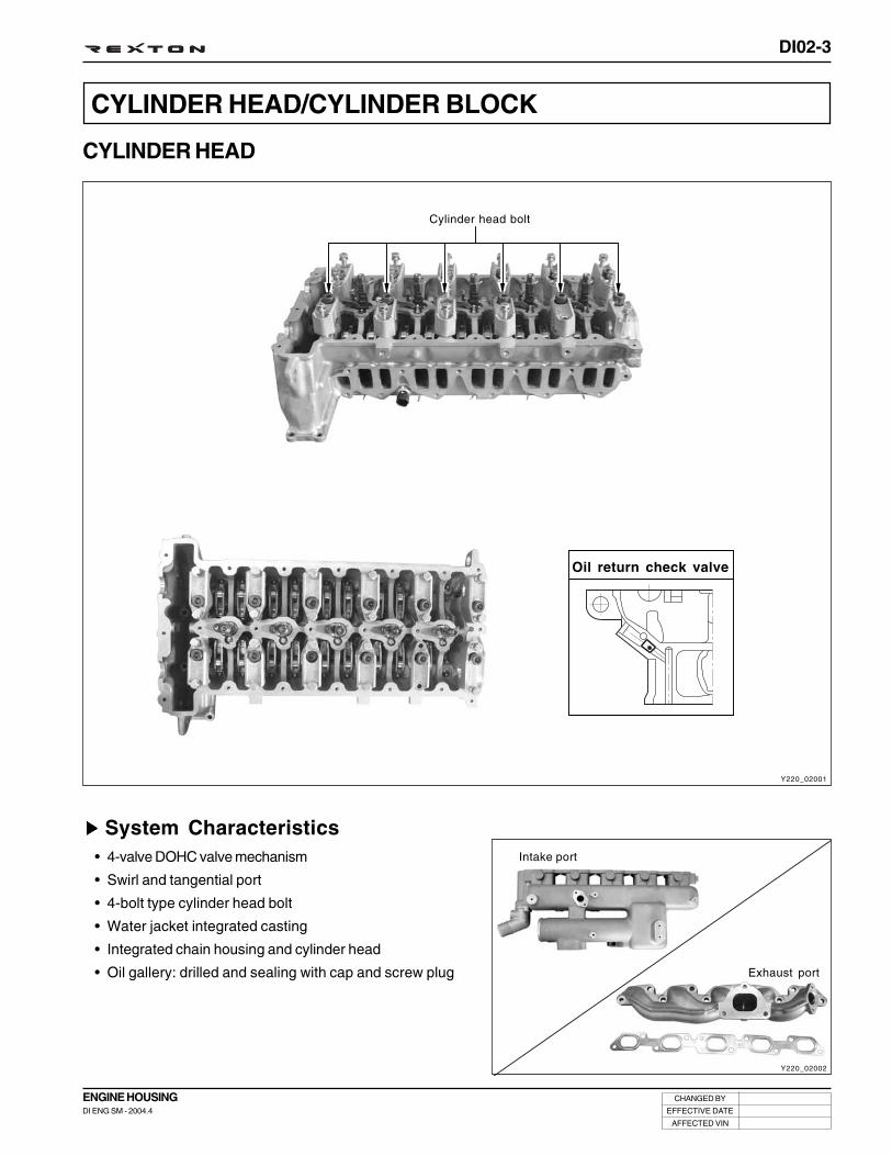
DI02-3
CHANGED BY
EFFECTIVE DATE
AFFECTED VIN
ENGINE HOUSINGDI ENG SM - 2004.4
Y220_02001
CYLINDER HEAD/CYLINDER BLOCK
CYLINDER HEAD
System Characteristics• 4-valve DOHC valve mechanism
• Swirl and tangential port
• 4-bolt type cylinder head bolt
• Water jacket integrated casting
• Integrated chain housing and cylinder head
• Oil gallery: drilled and sealing with cap and screw plug
Oil return check valve
Y220_02002
Cylinder head bolt
Intake port
Exhaust port

DI02-4
CHANGED BY
EFFECTIVE DATE
AFFECTED VIN
ENGINE HOUSINGDI ENG SM - 2004.4
Cylinder Head Pressure Leakage TestPreceding Works:
- Removal of cylinders
- Removal of intake and exhaust manifold
- Removal of valves
Test Procedures1. Place the pressure plate on a flat-bed work bench.
2. Install the cylinder head on the pressure plate.
3. Immerse the cylinder head with the pressure plate intowarm water (approx. 60°C) and pressurize withcompressed air to 2 bar.
Y220_02003
Y220_02004
Tightening torque 60 Nm
Notice
Examine the cylinder head for air bubbling. If the airbubbles are seen, replace the cylinder head.

DI02-5
CHANGED BY
EFFECTIVE DATE
AFFECTED VIN
ENGINE HOUSINGDI ENG SM - 2004.4
Height “A” (cylinder head parting surface - cylinder head cover parting surface)
Minimum height after machining
Permissible unevenness of parting surface
Permissible variation of parallelism of top parting surface to bottom in longitu-
dinal direction
Peak-to-valley height
Valve recess “a”
Specifications
in longitudinal direction
in transverse direction
Intake valve
Exhaust valve
142.9 ~ 143.1 mm
142.4 mm
0.08 mm
0.0 mm
within 0.1 mm
0.004 mm
0.1 ~ 0.7 mm
0.1 ~ 0.7 mm
Cylinder Head Parting Surface Check
Y220_02005
Y220_02006
Measurement
1. Measure the cylinder head height “A”.
2. Insert the valves into the valve guides and measure therecesses.
Notice
If the height is less than the limit, the cylinder headmust be replaced.
Limit Over 142.4 mm
Valve recess “a” 0.1 ~ 0.7 mm
Notice
If the measured value is out of the specified range,machine the valve seat as much as necessary untilthe specified value is achieved.

DI02-6
CHANGED BY
EFFECTIVE DATE
AFFECTED VIN
ENGINE HOUSINGDI ENG SM - 2004.4
Y220_02007
Y220_02008
Y220_02010
Y220_02011
3. Mark on the intake camshaft sprocket and exhaustcamshaft sprocket for timing setting during installation.
2. Remove the camshaft position sensor.
• The intake manifold can be interfered by the sensorwhen installing.
DisassemblyPreceding Works:- Removal of fan belt- Removal of fuel supply and return lines- Removal of EGR related pipes- Removal of intake manifold mounting bracket- Removal of injector fuel line and connector, and glow plug
connector
1. Remove the cylinder head cover.
Cylinder Head- Disassembly and Reassembly
Notice
• Plug the openings of injector holes and commonrail with the protective caps.

DI02-7
CHANGED BY
EFFECTIVE DATE
AFFECTED VIN
ENGINE HOUSINGDI ENG SM - 2004.4
5. Hold the camshafts and remove the intake camshaftsprocket and exhaust camshaft sprocket.
4. Remove the chain tensioner.
Preceding work: removal of EGR pipe and oil dipstick tube
6. Pull out the lock pins with a sliding hammer and removethe upper guide rail.
7. Remove the oil cooler, then remove the intake manifold.
• The intake manifold can be interfered by the cylinderhead bolt (M8 x 50).
Y220_02015
Y220_02014
Y220_02013
Y220_02012
Notice
Correctly align the electronic control module ontothe shift plate by using two central pins wheninstalling.

DI02-8
CHANGED BY
EFFECTIVE DATE
AFFECTED VIN
ENGINE HOUSINGDI ENG SM - 2004.4
10. Remove the cylinder head.
11. Measure the piston protrusion from the parting surface.
• Specified Value: 0.765 ~ 1.055 mm
9. Measure the length of cylinder head bolts.
• If the maximum length is exceeded by 2 mm, replacethe cylinder head bolt.
8. Remove the cylinder head bolts according to thenumerical sequence.
M8 x 25 : 2 EAM8 x 50 : 2 EAM12 x 177 : 11 EAM12 x 158 : 1 EA (Vacuum pump side)
Y220_02016
Y220_02019
Y220_02018
Y220_02017
Notice
• Inspect the cylinder head surface.
• Store the removed injectors and glow plugs so thatthey will not be damaged.
Length when new
177 mm
158 mm
Maximum Limit
179 mm
160 mm

DI02-9
CHANGED BY
EFFECTIVE DATE
AFFECTED VIN
ENGINE HOUSINGDI ENG SM - 2004.4
Y220_02020
Y220_02021
Y220_02022
Y220_02023
Reassembly1. Install the cylinder head with the steel gasket.
2. Tighten the cylinder head bolts to specified torque andtorque angle.
3. Install the HLA device and finger follower. Check the HLAdevice with the diagnosis procedures before installation.
4. Tighten the camshaft bearing cap bolts.
• Intake: #2, #4, #5
• Exhaust: #8, #10, #11
Notice
• Put the cylinder head on the locating pins.
Notice
• Apply the oil on the bolt thread when installing.• Always insert new washer first.• The bolts (12) at vacuum pump side are shorter than
others.
Notice
Make sure to place the “TOP” mark upward.
Tightening torque
Step 1 20 ± 2.0 Nm
Step 2 85 ± 5.0 Nm
Step 3 270° (90° x 3) + 10°

DI02-10
CHANGED BY
EFFECTIVE DATE
AFFECTED VIN
ENGINE HOUSINGDI ENG SM - 2004.4
• Exhaust: #1, #3, #6
• Intake: #7, #9, #12
Tightening torque 25 Nm
5. Install the intake and exhaust camshaft sprockets andthe timing chain.
Tightening torque 25 Nm + 90°
6. Rotate the crankshaft pulley two revolutions and ensurethat the OT mark on the crankshaft pulley and the OTmark on the camshaft pulley are aligned.
7. Place the bearing cap with the OT marks on bothcamshafts facing upward.
Y220_02024
Y220_02025
Y220_02026
Y220_02027
Notice
Check the finger follower positions and align ifneeded.
Notice
• If the sprocket bolt is stretched over 0.9 mm, replaceit with new one.
• Always install the intake camshaft sprocket first.• Ensure that the markings on camshaft sprocket and
timing chain are aligned.• Make sure that the timing chain is securely seated
on the guide rail.
Notice
If the markings are not aligned, reinstall the cylinderhead.
Notice
• Apply the sealant on the cap (#12) for the vacuumpump when installing.
• Apply the oil on the bearing journals beforeinstallation.
Intake
Exhaust

DI02-11
CHANGED BY
EFFECTIVE DATE
AFFECTED VIN
ENGINE HOUSINGDI ENG SM - 2004.4
8. Fit the timing chain onto the camshaft sprockets andinstall the upper guide rail.
• Install the clamping guide rail pin.
9. Tighten the intake and exhaust camshaft sprocket bolts.
10. Install the camshaft position sensor.
11. Apply the Loctite to the bolt and tighten it.
Tightening torque 10 Nm
12. Check the intake camshaft before installing the vacuumpump.
13. Install the intake manifold. Install the oil cooler with newgasket.
Tightening torque 25 Nm
Tightening torque25 ± 2.5 Nm,
90° + 10°
Y220_02031
Y220_02030
Y220_02029
Y220_02028
Notice
Ensure that there is no leaks around the coolant linefor #1 cylinder
Notice
• Install the guide rail with slanted side facingforward.
• Be careful not to change the timing of HP pumpwhen fitting the timing chain.

DI02-12
CHANGED BY
EFFECTIVE DATE
AFFECTED VIN
ENGINE HOUSINGDI ENG SM - 2004.4
14. Install the chain tensioner.
17. Tighten the cylinder head cover bolts.
Notice
• Apply the sealant to the bolts for the vacuum pumpand the timing chain cover.
15. Install the cylinder head cover assembly.
16. Install the rubber gasket.
18. Check the parting surface of the #12 bearing cap and thecylinder head for contacting.
19. Check if the O-ring is installed in the vacuum pump.
20. Install the vacuum pump with the key groove aligned.
21. Tighten the vacuum pump mounting bolts.
Y220_02032
Y220_02033
Y220_02034
Y220_02037
Tightening torque 80 ± 8.0 Nm
Tightening torque 10 ± 1.0 Nm
Tightening torque 10 ± 1.0 Nm

DI02-13
CHANGED BY
EFFECTIVE DATE
AFFECTED VIN
ENGINE HOUSINGDI ENG SM - 2004.4
Y220_02035
Y220_02036
Y220_02038
22. Install the PCV valve assembly on the cylinder head.
24. Remove the protective caps and install the new fuel supplypipes.
Tightening torque 10 ± 1.0 Nm
23. Engage the engine oil hose and the PCV valve hose.
Notice
• To keep the cleanness and protect the components,the fuel pipes should be replaced with new ones.
• Be careful not to be mixed the fuel pipes becausethe pipe appearance of #1 and #3 cylinders and #2and #4 are same each other.

DI02-14
CHANGED BY
EFFECTIVE DATE
AFFECTED VIN
ENGINE HOUSINGDI ENG SM - 2004.4
1. Remove the cylinder head assembly.
Intake/Exhaust - Removal/Installation
2. Install the removed cylinder head on the assembly board(special tool) and set the supporting bar and lever (specialtool) on the cylinder head.
3. Push the valve spring seat down with the lever and removethe valve cotter, valve seat and valve spring.
Y220_02039
Y220_02040
Y220_02042
Y220_02041
4. Remove the valves from the cylinder head.

DI02-15
CHANGED BY
EFFECTIVE DATE
AFFECTED VIN
ENGINE HOUSINGDI ENG SM - 2004.4
Special Tools and Equipment
Y220_02050Y220_02049
Y220_02048Y220_02047
Y220_02046Y220_02045
Y220_02044Y220_02043
Name and Part Number Application
Compression pressure measur-ing adapter and gauge
Pressure plate (cylinder headpressure leakage test)
Pressure plate (intake camshaftpressure leakage test
Pressure plate (exhaust camshaftpressure leakage test)

DI02-16
CHANGED BY
EFFECTIVE DATE
AFFECTED VIN
ENGINE HOUSINGDI ENG SM - 2004.4
Y220_02058Y220_02057
Y220_02056Y220_02055
Y220_02053
Y220_02052Y220_02051
Name and Part Number Application
Cylinder head hanger
Supporting bar and lever
Guide pin extractor
Intake manifold guide pin
Y220_02054

DI02-17
CHANGED BY
EFFECTIVE DATE
AFFECTED VIN
ENGINE HOUSINGDI ENG SM - 2004.4
Y220_02059
CAMSHAFT ASSEMBLYPreceding Work: Removal of cylinder head cover
Finger follower and HLA Intake camshaft andexhaust camshaft
Camshaft position sensor Chain tensioner
Camshaft sprockets
Cylinder head

DI02-18
CHANGED BY
EFFECTIVE DATE
AFFECTED VIN
ENGINE HOUSINGDI ENG SM - 2004.4
<Circuit diagram of camshaft position sensor>Y220_02061
Y220_02060
Camshaft Position Sensor
The camshaft position sensor uses hall-effect to set the camshaft position and metallic-magnetic-material sensor end isattached on the camshaft and then rotates with it. If sensor protrusion passes camshaft position sensor’s semi-conduc-tor wafer, magnetic field changes direction of electron on the semi-conductor wafer to the current flow direction thatpasses through wafer from the right angle. When operation power is supplied from camshaft position sensor, camshafthall sensor generates signal voltage. The signal voltage will be 0V if protrusion and camshaft position sensor are nearand 5 V if apart.
ECU can recognize that the No. 1 cylinder is under compression stroke by using this voltage signal (hall voltage).
The rotating speed of camshaft is half of the crankshaft and controls engine’s intake and exhaust valves. By installingsensor on the camshaft, can recognize specific cylinder’s status, compression stroke or exhaust stroke, by usingcamshaft position when the piston is moving toward TDC (OT). Especially when started first, it is difficult to calculate thestroke of a specific cylinder with only crankshaft position sensor.
Accordingly, camshaft position sensor is necessary to identify the cylinders correctly during initial starting. However,when engine is started, ECU learns every cylinder of the engine with crankshaft position sensor signals so can run theengine even though the camshaft position sensor is defective during engine running.
<Location of camshaft position sensor> <Operation principle of hall sensor>
Gap
Hall voltage
Pulse generation
Sensor air gap
Tightening torque
Operating temperature
Cam angle ± 6°
0.2 ~ 1.8 mm
10 ~ 14 Nm
- 40 ~ 130°C
Camshaft sensor
Ground

DI02-19
CHANGED BY
EFFECTIVE DATE
AFFECTED VIN
ENGINE HOUSINGDI ENG SM - 2004.4
Preceding Works:
- Removal of fan belt
- Removal of fuel supply and return lines
- Removal of intake manifold mounting bracket
Removal
1. Remove the injector fuel line and connector, and glowplug connector
2. Remove the cylinder head cover.
3. Remove the camshaft position sensor.
Y220_02065
Y220_02063
Y220_02062
Notice
Plug the openings of injector holes and common railwith the protective caps.

DI02-20
CHANGED BY
EFFECTIVE DATE
AFFECTED VIN
ENGINE HOUSINGDI ENG SM - 2004.4
7. Remove the camshaft bearing cap bolts so that thetightening force can be relieved evenly.
• Intake: #1, #3, #6
• Exhaust: #7, #9, #12
* However, there is no specific removal sequence.
5. Remove the chain tensioner.
Preceding work: removal of EGR pipe and oil dipstick tube
6. Hold the camshafts and remove the intake camshaftsprocket and exhaust camshaft sprocket.
4. Mark on the intake camshaft sprocket and exhaustcamshaft sprocket for timing setting during installation.
Y220_02069
Y220_02068
Y220_02067
Y220_02066
Intake
Exhaust

DI02-21
CHANGED BY
EFFECTIVE DATE
AFFECTED VIN
ENGINE HOUSINGDI ENG SM - 2004.4
• Intake: #2, #4, #5
• Exhaust: #8, #10, #11
* Do not remove the bolts at a time completely. Removethem step by step evenly or camshaft can be seriouslydamaged.
8. Remove the intake and exhaust camshafts from thecylinder head.
9. Remove the finger follower and the HLA device.
Y220_02071
Y220_02070
Notice
Avoid contact with hot metal parts when removingthe HLA device immediately after stopping theengine.

DI02-22
CHANGED BY
EFFECTIVE DATE
AFFECTED VIN
ENGINE HOUSINGDI ENG SM - 2004.4
1. Install the HLA device and finger follower. Check the HLAdevice with the diagnosis procedures before installation.
2. Place the bearing cap with the OT marks on bothcamshafts facing upward.
3. Tighten the camshaft bearing cap bolts.
• Intake: #2, #4, #5
• Exhaust: #8, #10, #11
• Intake: #1, #3, #6
• Exhaust: #7, #9, #12
Tightening torque 25 Nm
Installation
Y220_02072
Y220_02073
1 2 3 4 5 6
7 8 9 10 11 12
Y220_02074
1 2 3 4 5 6
7 8 9 10 11 12
Y220_02075
Notice
• Put the cylinder head on the locating pins.
Notice
• Apply the sealant on the cap (#12) for the vacuumpump when installing.
• Apply the oil on the bearing journals beforeinstallation.
Notice
Check the finger follower positions and align ifneeded.
Intake
Exhaust

DI02-23
CHANGED BY
EFFECTIVE DATE
AFFECTED VIN
ENGINE HOUSINGDI ENG SM - 2004.4
6. Install the chain tensioner.
4. Install the intake and exhaust camshaft sprockets andthe timing chain.
Tightening torque 25 Nm + 90° + 10°
5. Rotate the crankshaft pulley two revolutions and ensurethat the OT mark on the crankshaft pulley and the OTmark on the camshaft pulley are aligned.
Tightening torque 80 ± 8.0 Nm
Y220_02079
Y220_02077
Y220_02076
Notice
If the markings are not aligned, reinstall the cylinderhead.
Notice
• If the sprocket bolt is stretched over 0.9 mm, replaceit with new one.
• Always install the intake camshaft sprocket first.
• Ensure that the markings on camshaft sprocket andtiming chain are aligned.
• Make sure that the timing chain is securely seatedon the guide rail.

DI02-24
CHANGED BY
EFFECTIVE DATE
AFFECTED VIN
ENGINE HOUSINGDI ENG SM - 2004.4
Y220_02083Y220_02082
Y220_02081Y220_02080
Special Tools and Equipment
Name and Part Number Application
HLA remover
Stem seal drift

DI02-25
CHANGED BY
EFFECTIVE DATE
AFFECTED VIN
ENGINE HOUSINGDI ENG SM - 2004.4
Y220_02084
TIMING CHAIN ASSEMBLY
Chain Drive System
System Layout
1. Exhaust camshaft sprocket
2. Upper guide rail
3. Intake camshaft sprocket
4. Clamping guide rail
5. HP pump sprocket
6. Lower guide rail
7. Oil pump tensioner
8. Oil pump sprocket
9. Crankshaft sprocket
10. Oil nozzle
11. Tensioner guide rail
12. Chain tensioner
Oil injecting direction

DI02-26
CHANGED BY
EFFECTIVE DATE
AFFECTED VIN
ENGINE HOUSINGDI ENG SM - 2004.4
Chain tensioner
The major function of tensioner is optimizing the movement of chain drive system by using spring constant and oilpressure in the tensioner.
The tensioner performs function of adjusting chain tension to be always tight, not loose, while engine running. By doingso, can reduce wears of each guide rail and sprocket.
Tightening torque65 ± 5.0 Nm
(Installed on the cylinder head)
Guide rail
Guide rail is used to optimize the movement of chain drive system like tensioner.
Guide rail can prevent chain slap when chain is extended and reduce chain wears.
Guide rail is needed especially when the distance between the sprockets are too long.
The material is plastic.
• Location of guide rail
- Tensioner guide rail: Between crankshaft sprocket and exhaust camshaft sprocket
- Upper guide rail: Between exhaust camshaft sprocket and intake camshaft sprocket
- Clamping guide rail: Between intake camshaft sprocket and HP pump sprocket
- Lower guide rail: Between HP pump sprocket and crankshaft sprocket
Chain• Chain type: Double Bush
• Pitch: 9.525 mm
• Load limits: 19,000 N
• No. of links: 144 EA
• Overall length: 1371.6 mm
• Replace when the chain is extended by 0.5 % from overall length (Replace if extended by over 6.858 mm)
Y220_02085
Check valve
* Check valve opening pressure: 0.2 ~ 0.5 bar

DI02-27
CHANGED BY
EFFECTIVE DATE
AFFECTED VIN
ENGINE HOUSINGDI ENG SM - 2004.4
Y220_02086
Timing setting
• Check marking links on the chain (Gold marking)
• Locate a point with two continuous marking links and align it to a marking on crankshaft sprocket ( )
• Align respective marking link to each camshaft sprocket (intake and exhaust) marking ( )
• Align another marking link to HP pump sprocket marking ( )
<Timing marking points on chain>
Sprocket marking: 4 points
(Gold marking)

DI02-28
CHANGED BY
EFFECTIVE DATE
AFFECTED VIN
ENGINE HOUSINGDI ENG SM - 2004.4
Y220_02087
Y220_02088
Y220_02089
Y220_02090
1. Remove the cylinder head assembly.
2. Remove the oil pan.
3. Remove the chain guide rail with a sliding hammer.
4. Remove the chain cover.
Removal and Installation
9. Remove the tensioning guide rail.
5. Remove the oil pump drive chain.
6. Remove the upper guide rail while pushing the retainingspring with a screwdriver.
7. Remove the lower guide rail.
8. Remove the oil pump drive chain.
10. Remove the timing chain.
11. Install in the reverse order of removal.
* Thoroughly clean the removed components beforeinstalling.
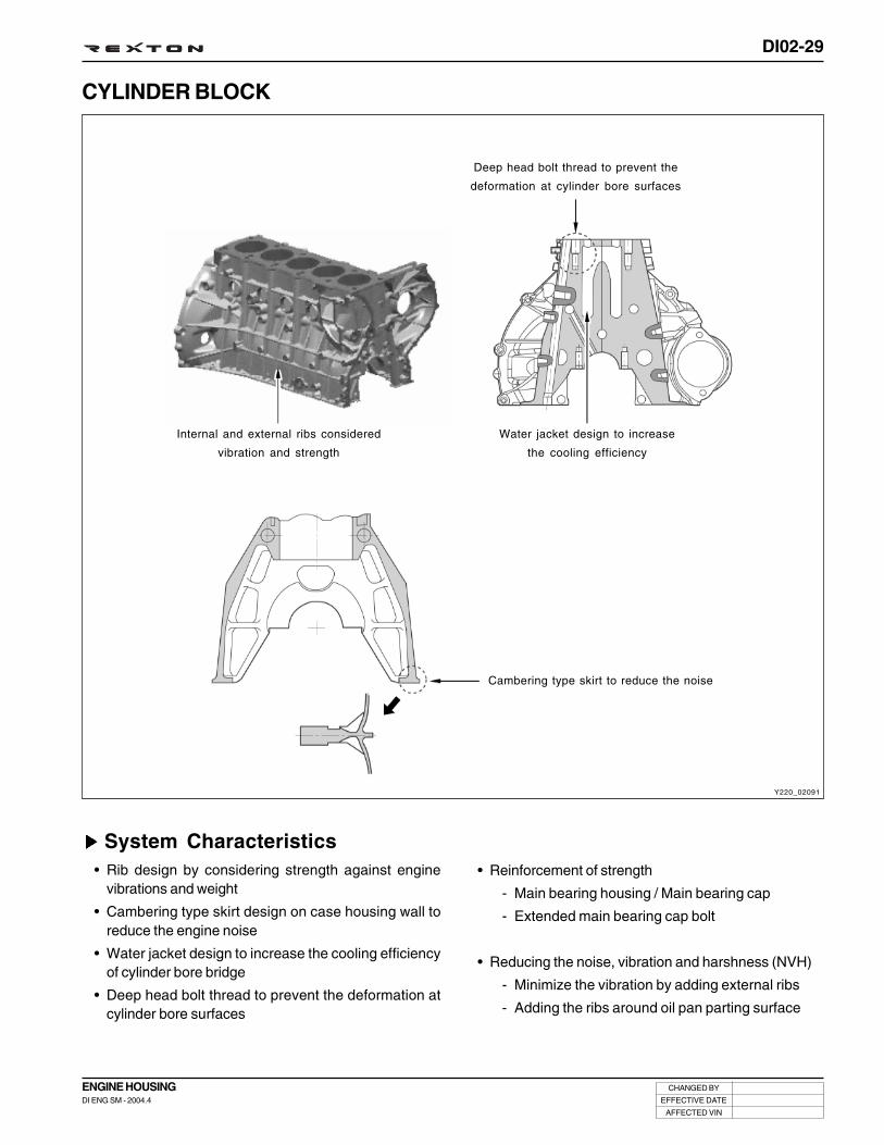
DI02-29
CHANGED BY
EFFECTIVE DATE
AFFECTED VIN
ENGINE HOUSINGDI ENG SM - 2004.4
CYLINDER BLOCK
System Characteristics• Rib design by considering strength against engine
vibrations and weight
• Cambering type skirt design on case housing wall toreduce the engine noise
• Water jacket design to increase the cooling efficiencyof cylinder bore bridge
• Deep head bolt thread to prevent the deformation atcylinder bore surfaces
• Reinforcement of strength
- Main bearing housing / Main bearing cap
- Extended main bearing cap bolt
• Reducing the noise, vibration and harshness (NVH)
- Minimize the vibration by adding external ribs
- Adding the ribs around oil pan parting surface
Water jacket design to increase
the cooling efficiency
Internal and external ribs considered
vibration and strength
Deep head bolt thread to prevent the
deformation at cylinder bore surfaces
Cambering type skirt to reduce the noise
Y220_02091

DI02-30
CHANGED BY
EFFECTIVE DATE
AFFECTED VIN
ENGINE HOUSINGDI ENG SM - 2004.4
Y220_02092
Knock SensorTwo knock sensors are located on the cylinder block (intake manifold side).To detect engine vibration under abnormal combustion, knock sensor has piezoelectric element fixed on thevibration plate and this vibration plate is fixed on the base. If happens knocking, pistons or connecting rodsvibrate and occurs heavy sounds that hit metal. Knock sensor is used to detect those knockings caused byabnormal combustions. It controls idling stabilities and turns on the engine warning light when detects injectordamages. And also controls pilot injection very precisely during MAP learning.When knock sensor is defective, engine ECU corrects injection timing based on MAP values like engine speed,intake air volume and coolant temperature.
Before checking the knock sensor unit, be sure to check the tightening torque of the sensor and connectorconnecting conditions.
1. Sensor housing
2. Nut
3. Disc spring
4. Weight
5. Insulation disc
6. Upper contact plate
7. Piezo element
8. Lower contact plate
9. Body
10. Terminal
11. Resister
<Location of knock sensor>
Insulating resistance
Resonance frequency
Operating temperature
Output voltage
Tightening torque
Min. 1MΩ
25 kHz
- 40 ~ 150°C
26 ± 8 mV/g (at 5 kHz)
22 ~ 37 mV/g (3 ~ 10 kHz)
22 ~ 57 mV/g (10 ~ 20 kHz)
20 ± 5 Nm
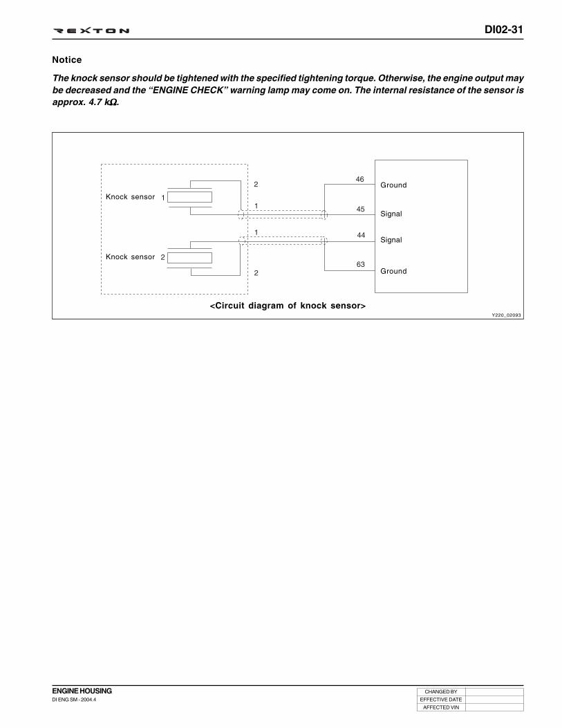
DI02-31
CHANGED BY
EFFECTIVE DATE
AFFECTED VIN
ENGINE HOUSINGDI ENG SM - 2004.4
Y220_02093
<Circuit diagram of knock sensor>
Ground
Signal
Signal
Ground
Notice
The knock sensor should be tightened with the specified tightening torque. Otherwise, the engine output maybe decreased and the “ENGINE CHECK” warning lamp may come on. The internal resistance of the sensor isapprox. 4.7 kΩΩΩΩΩ.
Knock sensor
Knock sensor

DI02-32
CHANGED BY
EFFECTIVE DATE
AFFECTED VIN
ENGINE HOUSINGDI ENG SM - 2004.4
Y220_02094
CRANKSHAFT
3. Crankshaft main bearing shells, upper
4. Upper thrust bearing
5. Crankshaft
6. Crankshaft main bearing shells, lower
7. Lower thrust bearing
8. Crankshaft main bearing cap
9. Crankshaft thrust bearing cap
10. 12-sided stretch bolt ....... 55 ± 5.0 Nm, 90° + 10°
Preceding Works: Removal of end coverRemoval of pistonsRemoval of crankshaft sprocket

DI02-33
CHANGED BY
EFFECTIVE DATE
AFFECTED VIN
ENGINE HOUSINGDI ENG SM - 2004.4
Y220_02095
1. Crankshaft
2. Crankshaft main bearing shells, upper
3. Upper thrust bearing
4. Crankshaft main bearing shells, lower
5. Lower thrust bearing
Notice
The clearance between bearing shell and bore and betweenbearing shell and journal are various. Refer to the tableon next page to select bearings when installing.
ARRANGEMENT OF THRUST WASHERS AND BEARINGS

DI02-34
CHANGED BY
EFFECTIVE DATE
AFFECTED VIN
ENGINE HOUSINGDI ENG SM - 2004.4
Dimensions of Crankshaft Main Bearing
Bearing Clearance
Matching the Fit Bearing Journal Width to Thrust Washers
Matching the Crankshaft Bearing Shells to Basic Bearing Bore in Crankcase
Notice
• Measure the crankshaft axial clearance and correct if necessary with appropriate thrust washers.
• Thrust washers of the same thickness must be installed on both sides of the fit bearing.
Matching Crankshaft Bearing Shells to Basic Bearing Journal of Crankshaft
(mm)
(mm)
(mm)
When new
Wear limit
When new
Wear limit
Radial clearance
Axial clearance
Crankshaft Bearing
0.027 ~ 0.051
Max. 0.070
0.100 ~ 0.254
Max. 0.300
Thrust Bearing
0.026 ~ 0.068
Max. 0.080
-
-
Description
Color
Blue
Yellow
Red
White
Violet
Crankshaft Journal
57.965 ~ 57.960
57.960 ~ 57.955
57.955 ~ 57.950
57.950 ~ 57.945
57.945 ~ 57.940
Upper Main Bearing
2.260 ~ 2.255
2.265 ~ 2.260
2.270 ~ 2.265
-
-
Lower Main Bearing
2.260 ~ 2.255
2.265 ~ 2.260
2.270 ~ 2.265
2.275 ~ 2.270
2.280 ~ 2.275
Fit bearing Journal Width
24.500 ~ 24.533
24.600 ~ 24.633
24.70 ~ 24.733
24.900 ~ 24.933
25.000 ~ 25.033
Thrust Washer Thickness
2.15
2.20
2.25
2.35
2.40
Marking of Bearing journals on Crank Webs
blue or white - blue
yellow or white - blue
red or white - blue
Relevant Crankshaft Bearing Shell With Color Coding
blue or white - blue
yellow or white - yellow
red or white - red
Marking of Basic Bearing Bore in Lower Parting Surface
1 punch mark or blue
2 punch marks or yellow
3 punch marks or red
Relevant Crankshaft Bearing Shell With Color Coding
blue or white - blue
yellow or white - yellow
red or white - red

DI02-35
CHANGED BY
EFFECTIVE DATE
AFFECTED VIN
ENGINE HOUSINGDI ENG SM - 2004.4
Selection of Upper Main Bearing Shell
Selection of Lower Main Bearing Shell
Y220_02096
Y220_02097
Punch Mark
•• •
• • •
Color
Blue
Yellow
Red
Mark
B
Y
R
W
V
Color
Blue
Yellow
Red
White
Violet

DI02-36
CHANGED BY
EFFECTIVE DATE
AFFECTED VIN
ENGINE HOUSINGDI ENG SM - 2004.4
Y220_02099
Y220_02098
Crankshaft Position Sensor
The crankshaft position sensor is located near to flywheel on the rear of cylinder block. It generates AC voltage betweenincrement type driven plate that fixed on flywheel inside. The sensor consists of soft iron core that winded copper wireon permanent magnet and generates sign wave AC voltage when magnetism on the sensor wheel passes the sensor.
When the crankshaft rotates, ‘+’ signal will be generated from near the front edge and ‘-’ signal will be generated fromnear the rear edge among teeth on the driven plate near to crankshaft position. The AC voltage increases as the enginespeed increases, however, no signal occurs from the 2-missing-tooth on the increment type driven plate. By using theseteeth, ECU recognizes TDC of No. 1 and 5 cylinders.
ECU converts the alternative signals into digital signals to recognize crankshaft position, piston position and enginespeed. The piston position that coupled with crankshaft is main factor in calculating injection timing. By analyzing thereference position and camshaft position sensor, can recognize No. 1 cylinder and calculate the crankshaft speed.
A. Distance between ‘+’ max. voltage and ‘-’ max.
voltage
a. Front edge
b. Rear edge
c. 2-missing-tooth
<Location of crankshaft position sensor>
<Drive plate>
<Structure of crankshaft position sensor>
Permanentmagnet
Ring gear
Iron
coilStandardposition

DI02-37
CHANGED BY
EFFECTIVE DATE
AFFECTED VIN
ENGINE HOUSINGDI ENG SM - 2004.4
Y220_02100
<Circuit diagram of crankshaft position sensor>
Output voltage( 1 ~ 150 V)
Sensor unit coil resistance (Ω)
Sensor air gap
Operating temperature
Tightening torque
Min. voltage: 1.0 V (40 rpm, air gap: 1.3 mm)
Max voltage: 150 V (7000 rpm, air gap: 0.3 mm)
1,090 ± 15 %
0.3 ~ 1.5 mm
- 40 ~ 150°C
6 ~ 8 Nm
Drive plate
Crankshaft positionsensor
Ground
Signal

DI02-38
CHANGED BY
EFFECTIVE DATE
AFFECTED VIN
ENGINE HOUSINGDI ENG SM - 2004.4
Y220_02101
TORSIONAL VIBRATION DAMPER
System Description• Components: Hub, inertia mass, cover, bearing, bushing, silicon oil
• Functions: The crankshaft pulley optimizes the drive system by reducing the amount of torsional vibration in crankshaft.Conventional rubber damper is limited in changing materials (rubbers) to absorb vibration, but this crankshaftpulley (viscous damper), using silicon oil, takes advantage of less changing viscosity according to thetemperature.
Laser welding
Hub
Pin
Silicone oil
Inertia ring
Bushing
Cover
Bearing

DI02-39
CHANGED BY
EFFECTIVE DATE
AFFECTED VIN
ENGINE HOUSINGDI ENG SM - 2004.4
1. Unscrew the bolts and remove the connecting rod journalbearing and bearing caps.
2. Remove the bearing cap bolts.
3. Remove the bearing caps.
Notice
Position the #1 piston at TDC and remove the pistonconnecting rod journal bearing caps.
4. Remove the bearing caps and lower thrust bearing.
5. Separate the lower bearing shells from the bearing caps.
Notice
• The crankshaft bearing caps are marked withstamped numbers. Start to remove from thecrankshaft pulley side.
• Do not mix up the bearing shells.
Crankshaft - Disassembly
Notice
Do not mix up the bearing shells.
Y220_02102
Y220_02103
Y220_02104
Y220_02105
6. Remove the crankshaft.
7. Remove the upper thrust washers.
8. Remove the upper bearing shells from the crankcase.

DI02-40
CHANGED BY
EFFECTIVE DATE
AFFECTED VIN
ENGINE HOUSINGDI ENG SM - 2004.4
Notice
The retaining lugs should be positioned in the grooves(arrow).
Notice
If the maximum permissible length of L= 63.8 mm isexceeded, the 12-sided stretch bolts should bereplaced.
2. Coat the upper thrust washers with oil and insert into thecrankcase so that the oil grooves are facing the crankwebs (arrow).
3. Coat the lower thrust washers with oil and insert into thecrankcase so that the oil grooves are facing the crankwebs (arrow).
1. Thoroughly clean the oil galleries and check the journalsection and bearings. Replace if necessary.
4. Coat the new crankshaft with engine oil and place it onthe crankcase.
5. Install the crankshaft bearing caps according to themarkings and tighten the bolts.
Tightening torque 55 ± 5 Nm + 90° + 10°
Notice
Install from #1 cap.
Y220_02106
Y220_02107
Y220_02108
Y220_02109
Crankshaft - Reassembly

DI02-41
CHANGED BY
EFFECTIVE DATE
AFFECTED VIN
ENGINE HOUSINGDI ENG SM - 2004.4
Y220_02110
6. Position the #1 piston at TDC and install the crankshaft.
7. Install the piston connecting rod journal to the crankshaftjournal and tighten the bolts.
8. Measure the crankshaft bearing axial clearance.
• When new: 0.100 ~ 0.245 mm
• When used: 0.300 mm
9. Rotate the crankshaft by hand and check whether itrotates smoothly.

DI02-42
CHANGED BY
EFFECTIVE DATE
AFFECTED VIN
ENGINE HOUSINGDI ENG SM - 2004.4
Y220_02111
FLYWHEEL
System DescriptionThis flywheel is installed to the rear end of crankshaft and transfers the output from the engine to the power trainmechanism. When starting the engine, this drive the crankshaft train mechanism initially by using the power from thestart motor. Also, DMF measure the crankshaft speed, sends the signals to ECU, and controls the ignition timing.
Y220_02147
DUAL MASS FLYWHEEL (DMF, MANUAL TRANSMISSION EQUIPPED VEHICLE)
Primary wheel
Primary wheel
Secondarywheel
Ring gear
Plastic bushing
Conventional flywheel DMF

DI02-43
CHANGED BY
EFFECTIVE DATE
AFFECTED VIN
ENGINE HOUSINGDI ENG SM - 2004.4
Y220_02112
<Example of DMF operation>
Y220_02113
System Characteristics
Function
• Filters irregularities of engine: The secondary flywheeloperates almost evenly so does not cause gear noises
• The mass of the primary flywheel is less thanconventional flywheel so the engine irregularityincreases more (less pulsation absorbing effect)
• Transmission protection function: Reduces the load topowertrain (transmission) by blocking the irregularityof engine
Characteristics of DMF• Reduced vibration noise from the powertrain by blocking
the torsional vibrations
• Enhanced vehicle silence and riding comforts: reducedengine torque changes
• Reduced shifting shocks
• Smooth acceleration and deceleration
Structure
Function and characteristics
• When the output changes from the engine is high duringpower stroke ( ): The damper absorbs the shocks toreduce the changes to transmission.
• When the output changes from the engine is low duringcompression stroke ( ): The damper increases the torquechanges to clutch.
Advantages of DMF
• Improved torque response by using 3-stage type spring:Strengthens the torque response in all ranges (low,medium, and high speed) by applying respective springconstant at each range.
• Stable revolution of the primary and secondary wheelby using planetary gear: Works as auxiliary damperagainst spring changes
• Less heat generation due to no direct friction againstspring surface: Plastic material is covered on the springouter surface
• Increased durability by using plastic bushing (extendsthe lifetime of grease)
<Torque change curve of engine and drive shaft>
An
gu
lar
acc
ele
ratio
n a
mp
litu
de
[1
/s2]
Speed [rpm]
Conventional system
Speed [rpm]
DMFW
Transmission
Engine
Transmission
Engine

DI02-44
CHANGED BY
EFFECTIVE DATE
AFFECTED VIN
ENGINE HOUSINGDI ENG SM - 2004.4
Y220_02114
1. Piston
2. No.1 compression ring
3. No.2 compression ring
4. Oil ring
5. Piston pin
6. Snap ring
PISTON AND CONNECTING ROD
Description
Cylinder bore diameter
Piston outer diameter (D1)
Clearance between bore and piston
Piston cooling gallery
Pin offset
Compression ratio
Length of piston pin
Material of top ring / coating
Tightening torque of connecting rod bolt
Permissible weight difference of connecting rod
Thickness of connecting rod bearing (Red)
Thickness of connecting rod bearing (Yellow)
Thickness of connecting rod bearing (Blue)
D27 DT ENG
φ 86.2 (0~0.018) mm
φ 86.133 (±0.009) mm
74
Applied
N/A
18 : 1
71.2 mm
Steel / Gas nitride
40 ± 5.0 Nm, 90° + 10°
4 g
1.806 ~ 1.809 mm
1.809 ~ 1.812 mm
1.812 ~ 1.815 mm

DI02-45
CHANGED BY
EFFECTIVE DATE
AFFECTED VIN
ENGINE HOUSINGDI ENG SM - 2004.4
Y220_02115
PISTON RING
1. No.1 compression ring
2. No.2 compression ring
3. Oil ring
5. Coil spring and oil control ring
6. Hook spring
Replacement of Piston Ring• Measure piston ring end play.
- Piston ring end play (mm)
1st groove: 0.20 ~ 0.35
2nd groove: 0.20 ~ 0.35
3rd groove: 0.20 ~ 0.40
- Clearance between piston ring and piston (mm)
1st compression ring: 0.075 ~ 0.119
2nd compression ring: 0.050 ~ 0.090
3rd oil ring: 0.030 ~ 0.070
• Install the piston so that “Y” marking on piston head isfacing in the direction of travel. Arrange the piston ringends to be 120° apart.
• Adjust the hook spring joint in the oil ring 180 ° away fromthe ring end.
Y220_02116

DI02-46
CHANGED BY
EFFECTIVE DATE
AFFECTED VIN
ENGINE HOUSINGDI ENG SM - 2004.4
Y220_02117
CYLINDER INNER DIAMETER AND PISTON SIZE
(Unit : mm)
Engine
D27DT
Code
A
X
B
+ 5
+ 10
Used piston
A or X
A, B or X
B or X
+ 5
+ 10
Cylinder Diameter
86.200 ~ 86.206
86.206 ~ 86.212
86.212 ~ 86.218
86.250 ~ 86.260
86.300 ~ 86.310
Piston Diameter
86.124 ~ 86.130
86.129 ~ 86.137
86.136 ~ 86.142
86.167 ~ 86.181
86.217 ~ 86.231

DI02-47
CHANGED BY
EFFECTIVE DATE
AFFECTED VIN
ENGINE HOUSINGDI ENG SM - 2004.4
1. Install the compression ring and oil ring on the pistonwith a special tool.
Piston - Reassembly
2. Check the clearance of piston oil ring and compressionring with a thickness gauge and adjust if necessary.
3. Check the clearance of piston rings with a thicknessgauge and adjust if necessary.
Notice
• Install the No.1 and No.2 pistons so that “Y” markingon piston head is facing upward.
• No.1 piston ring is thicker than No.2 piston ring.
• Arrange the oil ring end to opposite position ofcurrent ring end.
• Oil ring is not directional.
• Make sure that the piston ring end is not aligned toaxial direction and lateral direction.
1st groove
2nd groove
3rd groove
0.20 ~ 0.35 mm
0.20 ~ 0.35 mm
0.20 ~ 0.40 mm
No.1 compression ring
2nd compression ring
3rd oil ring
0.075 ~ 0.119 mm
0.050 ~ 0.090 mm
0.040 ~ 0.080 mm
Arrange the piston ring ends to be 120° apart.
* Piston ring end play (mm)
1st groove: 11.0 mm
2nd groove: 10.5 mm
3rd groove: 7.0 mm
Y220_02118
Y220_02119
Y220_02120
Y220_02121

DI02-48
CHANGED BY
EFFECTIVE DATE
AFFECTED VIN
ENGINE HOUSINGDI ENG SM - 2004.4
Notice
The snap rings should be replaced with new one.
5. Lubricate piston pin and push in by hand.
4. Fit the piston onto connecting rod so that the markingon piston crown and locking slot are facing to straightahead direction.
Notice
Install the piston so that the piston recess (marking)or the stamped surface of connecting rod is facing tostraight ahead direction.
Notice
Do not heat up the piston.
6. Place new snap rings into the grooves.
7. Lubricate the cylinder bore, connecting rod bearingjournals, connecting rod bearing shells and pistons.
8. Push piston into the cylinder with a wooden stick.
Notice
The marking on the piston crown must be facing tostraight ahead direction.
9. Insert connecting rod bearing shells.
Notice
• The upper and lower connecting rod bearings havesame appearance. Therefore, make sure to checkthe part number before replacing them.
• Install bearing rod bearing cap so that so that theretaining lugs are on the same side of theconnecting rod bearing.
Y220_02122
Y220_02123
Y220_02124
Y220_02125

DI02-49
CHANGED BY
EFFECTIVE DATE
AFFECTED VIN
ENGINE HOUSINGDI ENG SM - 2004.4
10. Measure stretch shaft diameter of the connecting rodbolts.
Limit “C” 7.1 mm
0.5 ~ 1.5 mmSpecified value
Y220_02126
Y220_02127
Y220_02128
40 ± 5.0 Nm,
90° + 10°Tightening torque
12. Position piston to TDC and measure the distance betweenpiston and parting surface of crankcase.
• Measure at both ends of axial direction.
11. Lubricate the new connecting rod bolts and tighten.
• End play of connecting rod cap
Permissible pistonprotrusion
0.765 ~ 1.055 mm

DI02-50
CHANGED BY
EFFECTIVE DATE
AFFECTED VIN
ENGINE HOUSINGDI ENG SM - 2004.4
Y220_02132Y220_02131
Y220_02130Y220_02129
Special Tools and Equipment
Name and Part Number Application
Piston protrusion measuring jig
Piston insertion jig

DI02-51
CHANGED BY
EFFECTIVE DATE
AFFECTED VIN
ENGINE HOUSINGDI ENG SM - 2004.4
HIGH PRESSURE PUMP (HPP)
Y220_02133
1. Inlet Metering Valve (IMV)
2. Hydraulic pressure head
3. Plunger
4. Drive shaft and cam ring
5. Housing
6. Roller and shoe
7. Low pressure pump
8. Fuel temperature sensor
9. Venting
10. High fuel pressure supply line
11. Pressure regulator
COMPONENTS LOCATOR
Low pressure line
High pressureline
Venturi return line
Fuel temperature sensor
High pressuresupply line
IMV connector
Inlet MeteringValve (IMV)

DI02-52
CHANGED BY
EFFECTIVE DATE
AFFECTED VIN
ENGINE HOUSINGDI ENG SM - 2004.4
HP Pump - Disassembly and Reassembly
Preceding works:
- Removal of fan belt (including cooling fan and fan clutch)and fan shroud
- Removal of intake manifold assembly
- Removal of water pump pulley
- Removal of auto tensioner
- Removal of EGR pipe
- Removal of oil dipstic gauge
Notice
• To prevent oil leaks, store the removed auto tensionerin upright position.
• Be careful not to damage the rubber bellows.
• Plug the oil ports for HP pump with sealing caps.
1. Set crankshaft pulley to OT point. Open the oil filler capand check if the cam shaft notch marking is aligned toOT point.
2. Remove the cooling fan idle pulley with a pulley holder(special tool).
Y220_02134
Y220_02136
Y220_02135

DI02-53
CHANGED BY
EFFECTIVE DATE
AFFECTED VIN
ENGINE HOUSINGDI ENG SM - 2004.4
3. Remove the cooling fan bracket assembly.
4. Place the marks on the chain and HP pump sprocket forinstallation.
5. Remove the vacuum modulator bracket.
6. Remvoe the fuel pipes and wiring connectors whichconnected to fuel pump.
Notice
Be careful not to get the sealant or foreign materialsinto the engine.
Y220_02137
Y220_02138
Y220_02148
Y220_02149
7. Turn the crankshaft pulley to the counter clockwisedirection to ATDC 45° then remove the chain tensioner.
Installation Notice
Tightening torque 80 ± 8Nm

DI02-54
CHANGED BY
EFFECTIVE DATE
AFFECTED VIN
ENGINE HOUSINGDI ENG SM - 2004.4
Y220_02139
10. Remove the sprocket bolts and center nut and afterslightly lifted up the chain, remove the pump sprocket.
Installation Notice
11. Remove the HP pump bearing with HP pump bearingpuller (special tool).
Tightening torque
Sprocket bolt
Center nut
Nm
20 Nm + 90°
65 ± 5 Nm
Y220_02141
Y220_02142
Notice
Do not apply excessive force. The timing chain maydeviates.
9. Install a special tool into the cooling fan bracket hole tohold the sprocket.
Y220_02140
8. While insert finger and push the chain guide backwarddirection and turn the crankshaft pulley to ATDC 65° bycounter clockwise direction until feel the chain guideinclined backward.

DI02-55
CHANGED BY
EFFECTIVE DATE
AFFECTED VIN
ENGINE HOUSINGDI ENG SM - 2004.4
12. Remove the HP pump mounting bracket.
Installation Notice
13. Unscrew the external bolts and remove the HP pumpwhile rocking and tapping it with a rubber hammer.
Tightening torque 24 ± 2.4 Nm
Y220_02143
Y220_02144
Notice
• To prevent HP pump shaft damaging, do not applyexcessive impact.
• Do not apply excessive force. The timing chain maydeviates.
Y220_02145
14. Remove the HP pump.
15. Install the new HP pump with sealing caps.
16. When replaced the HP pump, initialize the fuel pressureby using SCAN-100. Refer to “Trouble Diagnosis” sectionin this manual.
Notice
Remove the sealing caps only when connecting thepipes and hoses.

DI02-56
CHANGED BY
EFFECTIVE DATE
AFFECTED VIN
ENGINE HOUSINGDI ENG SM - 2004.4
Y220_02146
1. HP pump sprocket
2. 12-sided sprocket mounting bolt
3. HP pump bearing housing
4. HP pump (High Pressure Pump)
5. HP pump shaft
6. HP pump center nut
7. HP pump outer bolt
8. HP pump bearing shaft
9. Oil gallery
10. Bearing bushing
11. Gasket
* Tightening torque
Center nut
(M14 x 1.5 - 1EA)
Outer bolt
(M8 x 55 - 3EA)
Sprocket bolt
(M7 x 13 - 3EA)
65 ± 5.0 Nm
24 ± 2.4 Nm
20 Nm ± 90°
Install in the reverse order of removal and tighten thefasteners with the specified tightening torque.
Notice
If the initialization of fuel pressure has not beenperformed, the engine ECU controls new HP pumpwith the stored offset value. This may cause the poorengine output.

INTAKE SYSTEM
SECTION DI03

DI03-1
CHANGED BY
EFFECTIVE DATE
AFFECTED VIN
INTAKE SYSTEMDI ENG SM - 2004.4
INTAKE SYSTEM
00SECTION DI03
Table of Contents
AIR FLOWS ................................................................. DI03-3
INTAKE SYSTEM LAYOUT ......................................... DI03-4
Components locator ............................................... DI03-4
Air cleaner ............................................................... DI03-5
Air flow sensor(hot film air mass sensor) ....................................... DI03-8
Intercooler ............................................................. DI03-14
Intake manifold assembly ..................................... DI03-16
SPECIAL TOOLS AND EQUIPMENT ........................ DI03-17


DI03-3
CHANGED BY
EFFECTIVE DATE
AFFECTED VIN
INTAKE SYSTEMDI ENG SM - 2004.4
Y220_03001
AIR FLOWS
Work Flow of Intake System
AirCleaner
HFMSensor
TurboCharger
IntercoolerIntake
Manifold
CombustionChamber in
Engine
Air Cleaner
HFM Sensor
Intake Air Outlet Hose Intercooler Intake Air Inlet Hose
Intake Manifold
Intake Valve(in combustion chamber)
Engine
TurboCharger

DI03-4
CHANGED BY
EFFECTIVE DATE
AFFECTED VIN
INTAKE SYSTEMDI ENG SM - 2004.4
Y220_03002
INTAKE SYSTEM LAYOUT
Air cleaner Intake manifold
HFM sensor Intercooler
COMPONENTS LOCATOR

DI03-5
CHANGED BY
EFFECTIVE DATE
AFFECTED VIN
INTAKE SYSTEMDI ENG SM - 2004.4
Y220_03003
AIR CLEANER
Specifications
Cover
Element
Housing
Element Type Dry-Element Type
* Initial cleaning: 5,000 km, Clean or change every 10,000 km as required.However, change every 30,000 km.
* If the vehicle is operated under severe condition (short distance driving, extensiveidling or driving in dusty condition): More frequent maintenance is required.
Service Interval

DI03-6
CHANGED BY
EFFECTIVE DATE
AFFECTED VIN
INTAKE SYSTEMDI ENG SM - 2004.4
Air Cleaner Element - Replacement
Preceding Work: Disconnection of negative battery cable
1. Disconnect the HFM sensor connector.
2. Loosen the locking clamp and remove the intake duct.
3. Unscrew the screws and remove the air cleaner cover.
4. Remove the air cleaner element. Clean or replace theelement as required.
Y220_03004
Y220_03005
Y220_03006

DI03-7
CHANGED BY
EFFECTIVE DATE
AFFECTED VIN
INTAKE SYSTEMDI ENG SM - 2004.4
1. Check the air cleaner body, cover and packing fordeformation, corrosion and damage.
2. Check the air duct for damage.
Air Cleaner Housing/Element - Check
3. Check the air cleaner element for clogging, contaminationand damage. If the element is partially clogged, removethe dust or foreign materials with the compressed air. Ifthe contamination is severe, replace it with new one. Also,be careful not to contaminate during the replacement.
4. Check the air cleaner housing for clogging, contaminationand damage.
5. If the inside of housing is contaminated, remove thecontaminants.
Air Cleaner Housing- Removal and Installation
Preceding Work: Removal of air cleaner cover
1. Set aside the return hose and remove the coolant reservoirbolts.
2. Remove the air cleaner housing bolts.
3. Install in the reverse order of removal.
Y220_03007
Y220_03008
Y220_03009
Y220_03010
Notice
When cleaning the air cleaner with compressed air,direct the air from inside (engine) to outside (ambientair). Otherwise, contaminants can get into the engine.

DI03-8
CHANGED BY
EFFECTIVE DATE
AFFECTED VIN
INTAKE SYSTEMDI ENG SM - 2004.4
<CI type HFM sensor structure>Y220_03011
AIR FLOW SENSOR (HOT FILM AIR MASS SENSOR)
1. Plug-in sensor
2. Cylinder housing
3. Protection grid
4. Hybrid cover
5. Measuring duct cover
6. Housing
7. Hybrid
8. Sensor
9. Mounting plate
10. O-ring
11. Temperature sensor
Air flow sensor is locating on the air intake passage between air cleaner and intake manifold and measures air volumeflows to engine combustion chamber and intake air temperature.
And intake temperature sensor built-in the sensor detects intake temperature.
Internal circuit of the air flow sensor is being used to control the voltage value to control the temperature to maintain theheating resistance (Rh) to 160°C that is higher temperature than intake air temperature that is measured by resistance(RI).
Temperature sensor of the heating resistance (Rh) is measured by resistance (Rs).
If temperature changes occur due to increasing/decreasing intake air volume, voltage of the heating resistance changesto maintain the intake air temperature changes to set value (160°C).
Control unit computes intake air volume based on voltage changes of heating resistance.
Intake air temperature is measured by NTC integrated in the sensor.
Change history
inner tube added + grid (No.3)added + sensing chip changed +sensing section design changed
Results
Durability has enhanced 60times (lab test results)

DI03-9
CHANGED BY
EFFECTIVE DATE
AFFECTED VIN
INTAKE SYSTEMDI ENG SM - 2004.4
<Structure of CI type HFM sensor>Y220_03012
Intake air temperature sensor is a part of HFM sensor and a thermister and resister and detects air temperaturechanges that flow into the engine. There occurs high resistance when temperature is low and low resistance when high(NTC type).
ECU supplies 5 V to intake air temperature sensor and then measures voltage changes to determine the intake airtemperature. When air in the intake manifold is cold, the voltage is high and air is hot, the voltage is low.
The reason for using HFM sensor is that this sensor is most proper in controlling accurate air-fuel ratio to meet the legalemission regulations. This sensor measures actual intake air mass into engine very accurately during specific instantacceleration and deceleration, and determines engine loads and detects intake air pulsation and air flows.
Main functions of HFM sensor are:
• Using for EGR feedback control
• Using for turbocharger booster pressure control valve control
• Using for fuel injecting compensation
CI type HFM sensor: The air flowing the sensor does not directs toward sensing section but flows along with lower wallafter passing protection grid to enhance durability of the sensor. Oil, water and dust less damage the sensor.
Air outlet Air inlet

DI03-10
CHANGED BY
EFFECTIVE DATE
AFFECTED VIN
INTAKE SYSTEMDI ENG SM - 2004.4
Y220_03013
<Circuit diagram of HFM sensor>
Power supply
Intake airf l owsensor
Intake air temperaturesensor
HFM sensor
Signal
Ground
Ground

DI03-11
CHANGED BY
EFFECTIVE DATE
AFFECTED VIN
INTAKE SYSTEMDI ENG SM - 2004.4
Y220_03014
HFM sensor
HFM Sensor - Removal and Installation
Y220_03016
Y220_03015
Preceding Work: Disconnection of negative battery cable
1. Disconnect the negative battery cable.
2. Loosen the clamps on the air cleaner and the turbocharger and remove the duct.
3. Unscrew the bolts and remove the HFM sensor assembly.
Tightening torque 10 ± 1.0 Nm

DI03-12
CHANGED BY
EFFECTIVE DATE
AFFECTED VIN
INTAKE SYSTEMDI ENG SM - 2004.4
Y220_03017
Y220_03018
Y220_03019
Y220_03020
4. Install in the reverse order of removal.
Intake Air Outlet Hose (Turbo Charger)- Removal and Installation
1. Remove the radiator grille.
2. Loosen the clamp at both sides and remove the outlethose.
3. Loosen the clamp on the intake air hose and remove theintake air hose.
Installation Notice
Notice
Securely fasten the clamps on the pipes and hoses.
Tightening torque 6 ~ 7 Nm
4. Install in the reverse order of removal.

DI03-13
CHANGED BY
EFFECTIVE DATE
AFFECTED VIN
INTAKE SYSTEMDI ENG SM - 2004.4
Y220_03021
Y220_03022
Y220_03023
Y220_03024
1. Loosen the clamp at intercooler side.
2. Loosen the clamp at turbo charger side.
3. Separate the hose from the oil separator and remove theintake duct.
4. Install in the reverse order of removal.
Intake Air Inlet Duct (Air Cleaner)- Removal and Installation
Intake Air Inlet Duct (Intake Manifold)- Removal and Installation
1. Loosen the clamp on the inlet hose in intercooler.
2. Loosen the clamp at the intake manifold and remove theinlet hose.
Installation Notice
Tightening torque 6 ~ 7 Nm
3. Install in the reverse order of removal.

DI03-14
CHANGED BY
EFFECTIVE DATE
AFFECTED VIN
INTAKE SYSTEMDI ENG SM - 2004.4
Y220_03025
INTERCOOLERThe turbo charger is designed to improve the engine power by introducing more air (oxygen) into the engine. However,the intake air is heated (100 ~ 110°C) during the compression process in turbo charger compressor and the density islowered.
The intercooler is the device which cools (50 ~ 60°C) the air entering the engine. Colder air has more oxygen moleculesthan warm air. Thus cooler air gives more power and better fuel economy.
1. Intercooler

DI03-15
CHANGED BY
EFFECTIVE DATE
AFFECTED VIN
INTAKE SYSTEMDI ENG SM - 2004.4
Intercooler - Removal and Installation
1. Remove the radiator grille.
Tightening torque 10 ± 1.0 Nm
Tightening torque 6 ~ 7 Nm
Y220_03029
Y220_03028
Y220_03027
Y220_03018
2. Loosen the clamp at both sides (inlet and outlet) of theintercooler.
Installation Notice
3. Remove the intercooler mounting bolts.
Installation Notice
4. Remove the air duct in intake manifold and the intercoolerassembly.
5. Install in the reverse order of removal.

DI03-16
CHANGED BY
EFFECTIVE DATE
AFFECTED VIN
INTAKE SYSTEMDI ENG SM - 2004.4
Y220_03030
INTAKE MANIFOLD ASSEMBLY
System Characteristics• Shape that delivers the required capacity of compressed air from turbo charger to inlet port
• Optimized EGR gas mixture in inlet chamber
• Maximized intake efficiency with helical and tangential inlet port
- Improving the swirl ratio in low and mid operating range
- Improving the acceleration/fuel economy and reducing the maintenance in low and mid operating range
• Integrated inlet port and coolant outlet port

DI03-17
CHANGED BY
EFFECTIVE DATE
AFFECTED VIN
INTAKE SYSTEMDI ENG SM - 2004.4
Y220_03032Y220_03031
Name and Part Number Application
Intake manifold locking guide pin Installation of intake manifold
SPECIAL TOOLS AND EQUIPMENT

DI03-18
CHANGED BY
EFFECTIVE DATE
AFFECTED VIN
INTAKE SYSTEMDI ENG SM - 2004.4
Intake Manifold - Removal/InstallationPreceding Work: Disconnection of negative battery cable
1. Lift up the vehicle and remove the skid plate.
Y220_03033
Y220_03034
Y220_03035
Y220_03036
Notice
• Replace the pipes (2, 3) at both sides of EGR cooler(1) and gaskets with new ones.
• Make sure that the convex surface of gasket is facingto the pressurized direction.
2. Open the coolant reservoir cap and remove loosen thedrain cock to drain the coolant.
3. Remove the air inlet hose (1) from intake manifold.
4. Loosen the clamp and remove the coolant inlet hose (2).
5. Remove the coolant inlet port housing.
6. Remove the vacuum hose from EGR valve.
7. Remove the EGR valve mounting bolts and gasket.Remove the EGR exhaust pipe (primary) mounting boltsand gasket.

DI03-19
CHANGED BY
EFFECTIVE DATE
AFFECTED VIN
INTAKE SYSTEMDI ENG SM - 2004.4
8. Remove the brackets and connectors from top section ofthe engine.
- Vacuum hose bracket in turbo charger
- Booster pressure sensor
- Main wiring bracket
- Ground cable bracket
- Fuel pressure sensor connector
9. Unscrew the bolts and remove the vacuum modulatorbracket.
Tightening torque 9.0 Nm
10. Remove the HP pump fuel supply line bolts.
11. Remove the HP pump fuel supply line mounting bracket.
12. Remove the HP pump fuel return line at fuel filter.
13. Remove the injector return line at HP pump.
Y220_03037
Y220_03038
Y220_03039
Notice
• Be careful not to damage the pipes to HP pump.
• Plug the fuel return port of the HP pump with asealing cap.
Notice
• Plug the openings of pipes and ports with sealingcaps to keep the cleanness of the fuel system.
• Replace the pipes with new one once removed.

DI03-20
CHANGED BY
EFFECTIVE DATE
AFFECTED VIN
INTAKE SYSTEMDI ENG SM - 2004.4
14. Remove the intake manifold mounting bolts.
15. Lift up the vehicle and remove the propeller shaft jointbolts.
16. Unscrew the bolt in oil filter and remove the intakemanifold and gasket.
17. Install in the reverse order of removal.
Y220_03040
Y220_03041
Tightening torque 25 ± 2.5 Nm
Notice
1. Check the length of the bolts before installation.
M8 x 45: 6EA
M8 x 130: 6EA
Notice
• Replace the gasket with new one.
• Make sure that the residual coolant in intakemanifold gets into the inside of inlet port.
Notice
• Replace the gasket with new one.
• If replaced only gasket without any other serviceoperation, completely remove the coolant and othercontaminants from the engine before installation.

EXHAUST SYSTEM
SECTION DI04

DI04-1
CHANGED BY
EFFECTIVE DATE
AFFECTED VIN
EXHAUST SYSTEMDI ENG SM - 2004.4
EXHAUST SYSTEM
00SECTION DI04
Table of Contents
EXHAUST SYSTEM LAYOUT ..................................... DI04-3
Components locator ............................................... DI04-3
Exhaust gas flows ................................................... DI04-4
Turbo charger assembly ......................................... DI04-6
EGR VALVE AND VACUUM MODULATOR............... DI04-27
EGR system .......................................................... DI04-27
EGR valve and turbo charger actuatorcontrol vacuum circuit ........................................... DI04-28
EXHAUST SYSTEM AND MUFFLER ........................ DI04-36
Muffler ................................................................... DI04-36
System overview ................................................... DI04-37


DI04-3
CHANGED BY
EFFECTIVE DATE
AFFECTED VIN
EXHAUST SYSTEMDI ENG SM - 2004.4
Y220_04001
Muffler Exhaust manifold EGR valve
Vacuum modulatorTurbo chargerCatalytic converter
(DOC) EGR pipe
EXHAUST SYSTEM LAYOUT
COMPONENTS LOCATOR

DI04-4
CHANGED BY
EFFECTIVE DATE
AFFECTED VIN
EXHAUST SYSTEMDI ENG SM - 2004.4
Y220_04002
EXHAUST GAS FLOWS
Engine-Combustion
Chamber-
ExhaustManifold
TurboCharger
ExhaustMuffler
EGR ValveIntake
Manifold
Atmosphere
A
Catalytic converter Exhaust pipe Muffler
Atmo-sphere
A Exhaust gas
EGR vacuum modulator
To turbocharger booster
Turbo charger boostervacuum modulator
EGR valve
EGR pipe
Blow-by gas
Exhaust manifold
Turbo charger booster
Turbo charger(turbine side)

DI04-5
CHANGED BY
EFFECTIVE DATE
AFFECTED VIN
EXHAUST SYSTEMDI ENG SM - 2004.4
Tightening torque 35 ± 3.5 Nm
Tightening torque 40 ± 4.0 Nm
Y220_04006
Y220_04005
Y220_04004
Y220_04003
Exhaust Manifold- Removal and Installation
1. Remove the two intake hoses from the turbo charger.
2. Remove the turbo charger assembly (refer to TurboCharger section).
3. Remove the #3 pipe of EGR valve from the exhaustmanifold.
Notice
The #3 pipe of EGR valve is exposed to the hightemperature and pressure of exhaust gas. Replacethe gasket and pipe with new ones. Otherwise, it maycause the leakage of exhaust gas.
4. Unscrew the nuts and remove the exhaust manifold andgasket.
Notice
Replace the gasket with new one.
5. Install in the reverse order of removal.

DI04-6
CHANGED BY
EFFECTIVE DATE
AFFECTED VIN
EXHAUST SYSTEMDI ENG SM - 2004.4
Y220_04008
Y220_04007
TURBO CHARGER ASSEMBLYThe turbo charger is an air pump installed on the intake manifold. It enhances power and increases torque power ofengine to increase the fuel consumption rate. The engine without turbo charger cannot get as much power output as itinducts air by the means of vacuum being generated from descending strokes of the piston. Therefore, by installing theturbo charger on the intake manifold, it supplies great amounts of air to the cylinder increasing the volume efficiencyand, subsequently, enhances output power.
Also, as the engine’s power enhances, it increases the torque power and improves the fuel consumption rate. Theregular turbo charger operates by utilizing the pressure from the exhaust gas and the other, called Super Charger,operates by utilizing power from the engine. When the turbo charger is installed, weight of the engine increases by 10to 15 % whereas the output power increases by 35 to 45 %.
Operating Principle of Turbo ChargerThe turbo charger has one shaft where at each ends are in-stalled with two turbines having different angles to connectone end of housing to the intake manifold and the other end tothe exhaust manifold. As the turbine, at exhaust end, is ro-tated by exhaust gas pressure the impeller, at intake end,gets rotated to send air around center of the impeller, beingcircumferentially accelerated by the centrifugal force, into thediffuser.
The air, which has been introduced to the diffuser having apassage with big surface, transforms its speed energy intothe pressure energy while being supplied to the cylinder im-proving the volume efficiency. Also, the exhaust efficiencyimproves as the exhaust turbine rotates. The turbo charger isoften referred to as the exhaust turbine turbo charger.
Diffuser: With the meaning of spreading out it is a device thattransforms fluid’s speed energy into the pressure energy byenlarging the fluid’s passage to slow down the flow.
Impeller Turbine
Intercooler
Intake Exhaust
Intercoolercoolant

DI04-7
CHANGED BY
EFFECTIVE DATE
AFFECTED VIN
EXHAUST SYSTEMDI ENG SM - 2004.4
Y220_04009
1. Turbine housing
2. Turbine wheel
3. Compressor housing
4. Compressor wheel
5. Center housing
6. Turbo charger booster pressure control valve
7. Control link
8. Bypass flap
Construction of Turbo ChargerThe turbine wheel in turbo charger and compressor wheel are installed at each side of the shaft. It is comprised with theshaft supporting center housing (supporting the compressor with two float journal bearings), the turbine side parts ofTurbine Wheel, Shroud and Turbine Housing, and the compressor side parts of compressor wheel, back plate andcompressor housing.
• The turbine rotates turbine wheel by receiving exhaust gas energy from the engine.
• The compressor receives torque energy from the turbine and the compressor wheel inducts air to force it inside ofthe cylinder.
A. Air inlet (from atmosphere)
B. Exhaust gas inlet (from cylinder)
D. Exhaust gas outlet (to atmosphere)
E. Exhaust gas bypass passage
H. Oil supply opening
J. Oil return line

DI04-8
CHANGED BY
EFFECTIVE DATE
AFFECTED VIN
EXHAUST SYSTEMDI ENG SM - 2004.4
ImpellerThe impeller is wings (wheel) installed on the intake end andperforms the role of pressurizing air into the cylinder.
The radial type has the impeller plate arranged in straight lineat the center of shaft and, compared to the backward type, isbeing widely used as it is simple, easy to manufacture andappropriate for high speed rotation. As the impeller rotates inthe housing with the diffuser installed in it, the air receivescentrifugal force to be accelerated in the direction of housing’souter circumference and flows into the diffuser.
As surface of the passage increases, air flown into the dif-fuser transforms its speed energy into pressure energy andflows into the intake manifold where the pressurized air issupplied to cylinder each time the intake valve of cylinder opensup. Therefore, the efficiency of compressor is determined bythe impeller and diffuser.
TurbineThe turbine is wings installed at the exhaust end where, by the pressure of exhaust gas, it rotates the compressor andperforms the role of transforming heat energy of exhaust gas into torque energy. The radial type is used as the turbine’swings. Therefore, during operation of the engine, the turbine receives temperature of exhaust gas and it rotates in highspeed, it requires to have sufficient rigidity and heat resisting property.
During operation of the engine, exhaust gas discharged through the exhaust valve of each cylinder makes turbine rotateby coming in contact with the turbine’s wings from the outer circumference within housing of the turbine and is ex-hausted through the exhaust manifold. At the same time, as the impeller is on the same shaft, it rotates.
Floating BearingFloating Bearing is a bearing, which supports the turbine shaft that rotates at about 10,000 to 15,000 rpm. It could berotated freely between the housing and the shaft as it gets lubricated by oil being supplied from the engine.
Y220_04011
Y220_04010
Impeller
Turbine shaft
Turbine
Floating bearingThrust collar
Impeller
Turbine
Exhaust gas
Oil passageDiffuser
Notice
Stopping the engine immediately after driving at high speed stops oil from being supplied to the bearing andmay cause it to get burnt. Therefore, the engine must be stopped after cooling the turbo system by sufficientlyidling the engine.

DI04-9
CHANGED BY
EFFECTIVE DATE
AFFECTED VIN
EXHAUST SYSTEMDI ENG SM - 2004.4
Y220_04012
Booster Pressure Control Valve Unit (Turbo Charger Actuator)In order to reduce discharging of hazardous exhaust gas and to avoid the engine’s overrun the turbo charger must beappropriately controlled. The maximum turbo charging pressure must be controlled as excessive increase in the pres-sure and power output can cause critical damages to the engine. In order to control these, the booster pressure controlvalve is installed on the turbo charger.
The difference of the booster pressure control between the existing IDI engine and DI engine is that in IDI engine, boosterpressure of the intake manifold operates the booster pressure control valve connected directly to the turbo chargerwhereas in DI engine, the control is achieved by utilizing vacuum modulator (vacuum from a vacuum pump) designed tocontrol the booster pressure control valve. It operates booster pressure control valve by supplying electrical power to thevacuum modulator having the amount of air being flown into the HFM sensor from the engine’s ECU as the base signal.
Refer to the EGR section in following pages for the function of turbo charger and HFM sensor in exhaust system.
Booster pressure control valve unit and vacuum modulator
Turbo charger booster Turbo charger booster
vacuum modulator

DI04-10
CHANGED BY
EFFECTIVE DATE
AFFECTED VIN
EXHAUST SYSTEMDI ENG SM - 2004.4
Diagnosis and Maintenance for Turbo Charger System
Cautions During Driving
The following lists cautions to take during test drive andon the turbo charger vehicle, which must be consideredduring the operation;
1. It’s important not to drastically increase the enginerpm starting the engine. It could make rotation atexcessive speed even before the journal bearing islubricated and when the turbo charger rotates in pooroil supply condition, it could cause damage of bearingseizure within few seconds.
2. If the engine is running radically after replacing theengine oil or oil filter brings poor oil supply condition.To avoid this, it’s necessary to start off after idlingthe engine for about 1 minute allowing oil to circulateto the turbo charger after the replacement.
3. When the engine is stopped abruptly after driving athigh speed, the turbo charger continues to rotate incondition where the oil pressure is at ‘0’. In suchcondition, an oil film between the journal bearing andthe housing shaft journal section gets broken andthis causes abrasion of the journal bearing due to therapid contact. The repeat of such condition significantlyreduces life of the turbo charger. Therefore, the engineshould be stopped possibly in the idle condition.
Notice
After string for long period of time during winterseason or in the low temperature condition wherethe fluidity of engine oil declines, the engine,before being started, should be cranked tocirculate oil and must drive after checking the oilpressure is in normal condition by idling theengine for few minutes.
Inspection of Turbo Charger
When problem occurs with the turbo charger, it could causeengine power decline, excessive discharge of exhaust gas,outbreak of abnormal noise and excessive consumptionof oil.
1. Inspection when installed
- Check the bolts and nuts foe looseness or missing
- Check the intake and exhaust manifold forlooseness or damage
- Check the oil supply pipe and drain pipe fordamages
- Check the housing for crack and deterioration
2. Inspection of turbine in turbo charger
Remove the exhaust pipe at the opening of the turbineand check, with a lamp, the existence of interferenceof housing and wheel, oil leakage and contamination(at blade edge) of foreign materials.
- Interference: In case where the oil leak sign exists,even the small traces of interferences on theturbine wheel mean, most of times, that abrasionhas occurred on the journal bearing. Must inspectafter overhauling the turbo charger.
- Oil Leakage: Followings are the reasons for oilleakage condition;
• Problems in engine: In case where the oil issmeared on inner wall section of the exhaustgas opening.
• Problems in turbo charger: In case where theoil is smeared on only at the exhaust gasoutlet section.
Notice
Idling for long period of time can cause oilleakage to the turbine side due to low pressure ofexhaust gas and the rotation speed of turbinewheel. Please note this is not a turbo chargerproblem.

DI04-11
CHANGED BY
EFFECTIVE DATE
AFFECTED VIN
EXHAUST SYSTEMDI ENG SM - 2004.4
- Oil Drain Pipe Defect
In case where oil flow from the turbo chargersensor housing to the crank case is not smoothwould become the reason for leakage as oil buildsup within the center housing. Also, oil thickens(sludge) at high temperature and becomes theindirect reason of wheel hub section. In such case,clogging and damage of the oil drain pipe and thepressure of blow-by gas within the crank casemust be inspected.
- Damages from Foreign Materials
When the foreign materials get into the system,it could induce inner damage as rotating balanceof the turbo charger gets out of alignment.
Inspection of Turbine
Thoroughly check the followings.
Notice
Must absolutely not operate the turbo charger with thecompressor outlet and inlet opened as it could damagethe turbo charger or be hazardous during inspection.
- Interference: In case where is trace of interference orsmallest damage on the compressor wheel means,most of times, that abrasion has occurred on thejournal bearing. Must inspect after the overhaul.
- Oil Leakage: The reason for oil leakage at thecompressor section is the air cleaner, clogged bysubstances such as dust, causes the compressorinlet negative pressure;
A. Rotating in high speed at no-load for extendedperiod of time can cause oil leakage to thecompressor section as oil pressure within thecenter housing gets higher than pressure withinthe compressor housing.
B. Overuse of engine break (especially in low gear)in down hill makes significantly low exhaust gasenergy compared to the time where great amountof air is required during idling conditions of theengine. Therefore, amount of air in thecompressor inlet increases but the turbo chargepressure is not high, which makes negativepressure at the compressor section causing theoil leakage within the center housing.
Notice
No problem will occur with the turbo charger ifabove conditions are found in early stage but oilleaked over long period of time will solidify ateach section causing to breakout secondarydefects.
- Damages by foreign materials: In case where thecompressor wheel is damaged by foreign materialsrequires having an overhaul. At this time, it’snecessary to check whether the foreign materials havecontaminated intake/exhaust manifold or inside ofengine.

DI04-12
CHANGED BY
EFFECTIVE DATE
AFFECTED VIN
EXHAUST SYSTEMDI ENG SM - 2004.4
Path of Turbo Charger DefectThe following tries to understand the defects that can occur with vehicle installed with the turbo charger and to managethe reasons of such defects.
1. In case where oil pan/oil pipe has been contaminated, oil filter is defected and whereadhesive of gaskets has been contaminated into the oil line.
Contamination of Oil
Journal BearingDamage or Wear
Clogging of OilPassage
Metal Contact Poor Oil Supply
Shaft Journal Bearing Wear
Rotor Wear
Seal Wear atExhaust System
Interference ofTurbine and Com-
pressor Components
Oil Leakage
Seal Wear at IntakeSystem
Abnormal Noise Lack of Power/PoorAcceleration (Lack of
Turbo Charged Pressure)
Check Exhaust Gas PipesCheck Booster PressureControl Valve

DI04-13
CHANGED BY
EFFECTIVE DATE
AFFECTED VIN
EXHAUST SYSTEMDI ENG SM - 2004.4
2. Oil Pump Defect: Rapid over-loaded driving after replacing oil filter and oil and clogging of oilline.
Poor Oil Supply
Metal Contact of Shaft /Journal Bearing/Center Housing Inner Part
Journal Bearing/Center Housing Inner PartWear/Seizure
Seal Wear at ExhaustSystem
Interference of Turbine andCompressor Components
Oil Leakage
Seal Wear at IntakeSystem
Abnormal Noise
Melt down of Bearing to Turbine Wheel Journal
Rotor Rotational Movement
Lack of Power/PoorAcceleration (Lack of
Turbo Charged Pressure)

DI04-14
CHANGED BY
EFFECTIVE DATE
AFFECTED VIN
EXHAUST SYSTEMDI ENG SM - 2004.4
3. Turbine Side: Inflow of foreign materials from engineCompressor Side: such as air filter, muffler and nut
Inflow of Foreign Materials
Inflow of Foreign Materialsinto Turbine
Inflow of Foreign Materialsinto Compressor
Shaft Wheel Blade BreakCompressor Wheel Blade
Break
Unbalancing Rotor Rotation
Rotor Bearing Wear
Seal Wear at ExhaustSystem
Interference of Turbine andCompressor Components
Oil Leakage
Seal Wear at IntakeSystem
Abnormal NoiseLack of Power/Poor Accel-
eration (Lack of TurboCharged Pressure)
Rotor Turning Movement

DI04-15
CHANGED BY
EFFECTIVE DATE
AFFECTED VIN
EXHAUST SYSTEMDI ENG SM - 2004.4
4. Defects caused by reasons other than that of the Turbo Charger.
Oil Leakage at Turbine
Excessive Engine Wear
Oil Leakage at TurbineHousing Entrance
Carbonization Caused ByHigh Temperature
Misunderstanding of OilLeakage
Seal WearNo Problems in TurboCharger System
Oil Leakage
Excessive Inflow of Blow-ByGas, Idling at Low Speed,Clogging of Oil Drain Pipe
Inflow of Dust
Oil Leak Sign at Compres-sor Inlet and Outlet
Increase of Negative PressureIncrease at Inlet Side
No Problems in TurboCharger System
Excessive Inflow of Blow-ByGas, No-Load High Speed
Rotation
Oil Leakage at Compressor
Misunderstanding of OilLeakage
Oil Leakage at Seal
<MechanicalMalfunction>
Dampness or Poor Connec-tion of Turbo Charger ActuatorConnecting Vacuum Circuit
Detection of DTC CodeCaused By HFM Sensor or
EGR Valve Malfunction
Vacuum Modulator PowerControl Error for Controlling
Actuator in Engine ECU
<In case where the scannerdisplays as electrical malfunction>

DI04-16
CHANGED BY
EFFECTIVE DATE
AFFECTED VIN
EXHAUST SYSTEMDI ENG SM - 2004.4
How to DiagnoseThe followings are cautions to take in handling defects of turbo charger, which must be fully aware of;
Cautions When Examining the Defects:
1. After stopping the engine, check whether the bolts on pipe connecting section are loose as well as the connectingcondition of vacuum port and modulator, which is connected to the actuator.
2. During idling of the engine, check for leakage in the connecting section of pipe (hoses and pipes, duct connections,after the turbo charger) by applying soap water. The leakage condition in the engine block and turbine housingopening can be determined by the occurrence of abnormal noise of exhaust.
3. By running the engine at idle speed, abnormal vibration and noise can be checked. Immediately stop the enginewhen abnormal vibration and noise is detected and make thorough inspection whether the turbo charger shaftwheel has any damages as well as checking the condition of connections between pipes.
4. In case where the noise of engine is louder than usual, there is possibility of dampness in the areas related with aircleaner and engine or engine block and turbo charger. And it could affect the smooth supply of engine oil anddischarge. 5. Check for damp condition in exhaust gas when there is sign of thermal discoloration or discharge ofcarbon in connecting area of the duct.
6. When the engine rotates or in case where there is change in noise level, check for clogging of air cleaner or aircleaner duct or if there is any significant amount of dust in the compressor housing.
7. During the inspection of center housing, inspect inside of the housing by removing the oil drain pipe to check forsludge generation and its attachment condition at shaft area or turbine side.
8. Inspect or replace the air cleaner when the compressor wheel is damaged by inflow of foreign materials.
9. Inspect both side of the turbo charger wheel after removing inlet and outlet pipe of the turbo charger.
- Is the rotation smooth when the rotor is rotated by hand?
- Is the movement of bearing normal?
- Inspect whether there has been any signs of interference between two wheels.
Notice
It’s important not to drive the engine when the intake manifold hose has been removed.

DI04-17
CHANGED BY
EFFECTIVE DATE
AFFECTED VIN
EXHAUST SYSTEMDI ENG SM - 2004.4
Diagnosis and Measure
Poor Engine Power or Smoke Discharge
Air Cleaner Contaminationand Clogging of Oil Pass
Type Air Cleaner
Slack between Compres-sor Entrance and Exhaust
Manifold ConnectionLeaks at Intake Manifold
YES YES YES
Replace Air CleanerElement or Oil Pass Type
Air FilterReconnect Connections Inspect and Repair
Intake Manifold
NO
Leaks at Exhaust Mani-fold
Leaks at Turbo ChargerConnecting Flange
Poor Rotation or Interfer-ence of Turbo Charger
Components
NO NO
YES YES
Inspect and Repair IntakeManifold
Refer to DiagnosisTable
NO
Clogging Between AirCleaner and Compressor
Clogging Between Com-pressor Exit and Intake
ManifoldClogging of Engine MufflerNO NO
YES YES YES
Clean or Replace AffectedComponents
Clean or Replace AffectedComponents
Clean or ReplaceAffected Compo-
nents
NO
Clogging of Engine Intake/Exhaust Manifold
Weakness of EngineFunction, Intake/Exhaust
Valve Damage, TimingDefects of Each Valve
NO
YES
Inspect and RepairRelated Components
YES
Inspect and RepairRelated Components
NO NO

DI04-18
CHANGED BY
EFFECTIVE DATE
AFFECTED VIN
EXHAUST SYSTEMDI ENG SM - 2004.4
Before DiagnosisThe base of making diagnosis on the EGR related system is the inspection on the connections of the vacuum hoses inrelated system as the first priority. When abnormal condition occurs with the EGR system, the basic approach is, asdescribed in prior sentence, making detail inspections of vacuum circuits of each system before connecting the scantool or vacuum tester. It is necessary to manually check on the connections if there are any slacks or loose circuits evenif the visual inspection shows vacuum hose as being connected. If there are not any problems then the next inspectionarea is the connections of the system connectors. Most problems with the occurrence of system malfunction are fromconditions of vacuum line and connector connections and the causes from the malfunction of mechanical mechanism isactually very few.
For example, when there are no problems with basic components, let’s assume that there is a vehicle having vacuumleak from connection slack in the vacuum line between EGR vacuum modulator and EGR valve. This vehicle, due to thedriving condition or, according to the circumstances, smog or other conditions, could create customer’s complaint andby connecting the scanning device could display as the malfunction of the EGR valve’s potentiometer.
As previously explained, this car has a separate controller to control the Hoover EGR and, in accordance with variousinput element, the controller controls EGR valve by regulating the force of vacuum being applied to the EGR valve throughPWM control. At this time, the controller has to receive feedback whether the EGR valve operates correctly according tothe value sent to the EGR modulator and this role is performed by the EGR potentiometer located at top section of theEGR valve.
In other word, the controller sent correct output value to the EGR vacuum modulator but, due to the leakage of vacuum,signal of required value can not be received from the EGR potentiometer causing to display as malfunction of relatedparts.
As a reference, the EGR valve of diesel vehicle (DI Engine) controlling from the engine ECU to EGR system has differentshape than the Hoover EGR valve because the EGR valve’s operation signal in the DI engine is performed by the HFMsensor instead of the EGR potentiometer.
This principle is that when the EGR valve opens up to flow exhaust gas into the intake unit the amount of fresh air,comparatively, will be reduced. The DI engine ECU receives feedback signal of change in amount of air being passedthrough the HFM sensor according to the opening amount of the EGR valve.
Hoover EGR System for IDI Engine
(Including the EGR Valve Potentiometer)
EGR System for DI Engine
Y220_04013

DI04-19
CHANGED BY
EFFECTIVE DATE
AFFECTED VIN
EXHAUST SYSTEMDI ENG SM - 2004.4
The other big difference between the Hoover EGR and EGR controller for DI engine is that from two vacuum modulator,one is same as being the modulator for EGR valve whereas the Hoover EGR system’s the other modulator controlsALDA of injection pump and the DI engine’s the other modulator controls waist gate of the turbo charger.
This difference is in accordance with the difference in fuel injection method where the IDI engine has mechanicalinjection system and DI engine is capable of making electronically controlled fuel injection.
In other word, to reduce the amount of the fuel injection in no-load rapid acceleration mode, the IDI engine’s Hoover EGRutilizes solenoid valve to disconnect the connection circuit between intake manifold and ALDA causing negative pres-sure to occur in the vacuum modulator to reduce the amount of fuel injection. When DI engine, basing input signal fromthe related sensors such as acceleration pedal sensor and engine RPM, recognizes that current mode is the no-loadrapid acceleration mode it reduces the amount of fuel injection by sending short electrical signal to the injector. Therefore,disregarding the modulator for the EGR valve in DI engine, one must keep in mind that the other modulator is used tocontrol the booster pressure valve in turbo charger.

DI04-20
CHANGED BY
EFFECTIVE DATE
AFFECTED VIN
EXHAUST SYSTEMDI ENG SM - 2004.4
When Engine Exhaust Gas shows White Smog or Blue Smog
Poor Connection betweenCompressor Outlet and
Intake Manifold
Oil Leak Sign aroundIntake Manifold
Clogging of Engine OilElement
NO NO
YES YES YES
Reconnection Inspect PVC Line Replace Oil Filter
NO
Clogging or Damagebetween Air Cleaner and
Turbo
Oil Leakage at Sealbetween Turbo Charger
and Compressor
Engine Malfunction (Ring,Piston, Valve)
NO NO
YES YES
Clean or Replace AffectedComponents
Repair (overhaul)Engine
Improper Inspection of AirCleaner Contamination
Improper Viscosity ofEngine Oil Being Used
Poor Oil Seal at TurboCompressor Side (Oil leaksign at housing and wheel)
NO NO
YES YES YES
Replace Air CleanerElement
Replace with Specified Oil Refer to DiagnosisTable
NO
Poor Oil Seal at Turbo TurbineSide (trace of leakage in
housing and wheel)
Oil Leakage at EngineExhaust Manifold (damages
to ring, piston and valve)
NO
YES
Refer to Diagnosis Table
YES
Inspect or repair Manifold
YES
Refer to Diagnosis Table
Excessive Consumption of Engine Oil

DI04-21
CHANGED BY
EFFECTIVE DATE
AFFECTED VIN
EXHAUST SYSTEMDI ENG SM - 2004.4
Abnormal Noise from Turbo Charger System
Contamination or Cloggingof Air Cleaner
Leaks at Pipe and HoseDuct Parts between
Manifolds of Turbo Charger
Inflow of Foreign Materialto Compressor Entrance
or Housing
YES YES YES
Clean or Replace Ifrequired
Inspect or ReplaceConnections
NO
Inflow of Foreign Materialsto Intake Manifold
Inflow of Foreign Materialsto Muffler
Poor Rotation of RotatingTurbo Charger Compo-nents and Interference
YES YES
Inspect and Repair AirCleaner Element and Turbo
Charger after RemovingForeign Materials
Repair Housing andTurbo Charger and
Inspect Normal Opera-tion for Engine
NO
Check the Interferencebetween Rotating Turbo
Charger Components andHousing
YES
Refer to Diagnosis Table
Inspect and Repair AirCleaner Element and Turbo
Charger after RemovingForeign Materials
YES
Repair Muffler and TurboCharger After Removing
Foreign Materials
NO
NO NO
NO

DI04-22
CHANGED BY
EFFECTIVE DATE
AFFECTED VIN
EXHAUST SYSTEMDI ENG SM - 2004.4
Poor Rotation of the Turbo Charger
Compressor WheelDamages By Inflow of
Foreign Material
Turbine Wheel DamagesBy Inflow of Foreign
Material
Interference of Compres-sor Wheel with Housing
NO NO
YES YES YES
Repair or Replace AirCleaner Element and
Turbo Charger
Repair or Replace Ex-haust Manifold
NO
Clogging of Compressorby Dust
Excessive Deposit ofCarbon or Combustion
Residues Inside of TurbineWheel by Oil Contamination
Gel Type Oil in CenterHousing
NO NO
YES YES
Repair or Replace AirCleaner Element and
Turbo Charger
Repair or Replace EngineOil Filter and Turbo
Charger
Excessive Filling of OilWhen Installing
Clogging of Oil DrainPipes in Turbo Charger
Gel Type Oil in CenterHousing or Excessively
Contaminated Oil
NO NO
YES YES YES
Oil Disappears AfterCombustion
Clean or Replace DrainLine
Repair or ReplaceEngine Oil Filter and
Turbo Charger
NO
Deterioration of TurboCharger Journal
Poor Engine Function(Too High Blow-by gaspressure in crankcase)
NO
YES
Refer to Diagnosis Table
YES
Inspect PVC Line
YES
Repair or Replace TurboCharger
Oil Leakage at Turbine in Turbo Charger
Fatigue and Wear inBearing or ShaftJournal (Refer toDiagnosis Table)

DI04-23
CHANGED BY
EFFECTIVE DATE
AFFECTED VIN
EXHAUST SYSTEMDI ENG SM - 2004.4
Oil Leakage at Compressor in Turbo Charger
Contamination of AirCleaner Element Too High Oil Viscosity
Clogging or Damage ofPipe between Air Cleaner
and Turbo Charger
YES YES YES
Clean or Replace AirCleaner Element
Replace With SpecifiedOil
Replace DamagedComponents after
Cleaning clogged Area
NO
Looseness in Connectionbetween Compressor
Outlet and Intake Manifold
Oil Leakage at IntakeManifold
Clogging of Oil Drain Pipein Turbo Charger System
YES YES
Reconnect After Inspec-tion
Clean Clogged AreaAfter Inspection
NO
Deterioration or Damageto Compressor Wheel
Clogging Between Com-pressor Outlet and Intake
ManifoldClogging of Engine Muffler
YES YES YES
Clean, Repair or ReplaceAir Cleaner Element and
Turbo ChargerRefer to Diagnosis Table
YES
Inspect and Repair IntakeManifold
Inspect PCV Line
NO
NO
NO NO
NO
NO

DI04-24
CHANGED BY
EFFECTIVE DATE
AFFECTED VIN
EXHAUST SYSTEMDI ENG SM - 2004.4
Wear in Turbo Charger Inner Diameter and Shaft Journal
Poor Oil Filling WhenInstalling or Replacing
Turbo Charger
Contamination of Oil Filteror Use of Low Grade Oil
Lack of Oil in TurboCharger
NO NO
YES YES YES
Reinstall While UsingSpecified Oil
Clean or Replace AirCleaner Element / Re-
place With Specified Oil
NO
Poor Oil Supply byClogging of Oil SupplyPipe in Turbo Charger
Clogging of Engine OilFilter
Wear in Journal SectionBy Clogging in Center
Housing
NO NO
YES YES
Clean and Repair Dam-aged Components
Repair or ReplaceTurbo Charger
NO
Poor Function of EngineOil Pump
YES
Inspect and Replace IfRequired
Add Oil During Idling
YES
Replace Oil Filter
For other diagnosis, refer to Diagnosis section.

DI04-25
CHANGED BY
EFFECTIVE DATE
AFFECTED VIN
EXHAUST SYSTEMDI ENG SM - 2004.4
1. Remove the drain plug and drain the engine oil from theoil pan.
Installation Notice
Y220_04018
Y220_04017
Y220_04016
Y220_04015
Turbo Charger Assembly- Removal and Installation
2. Remove the vacuum hose and inlet hose from the turbocharger.
Installation Notice
3. Remove the bolts and nuts at the exhaust manifold inturbo charger.
Installation Notice
4. Remove the lower and upper bolts at turbo charger oilsupply pipe.
Installation Notice
Tightening torque 25 ± 2.5 Nm
Tightening torque 6 ~ 7 Nm
Tightening torque 25 ± 2.5 Nm
Tightening torque 23 ± 2.3 Nm

DI04-26
CHANGED BY
EFFECTIVE DATE
AFFECTED VIN
EXHAUST SYSTEMDI ENG SM - 2004.4
Y220_04022
Y220_04021
Y220_04020
Y220_04019
5. Remove the lower bolts at turbo charger oil return pipe.
Notice
Replace the steel gasket with new one.
Tightening torque 25 ± 2.5 Nm
6. Remove the lower bolt at turbo charger bracket.
7. Remove the turbo charger bracket bolts.
Installation Notice
Tightening torque 32 ± 3.2 Nm
Notice
Use only 12 1/2" wrench.
8. Remove the bolts and nuts at the turbo charger and theexhaust manifold.
Installation Notice
Tightening torque 25 ± 2.5 Nm
9. Remove the turbo charger assembly.
10. Install in the reverse order of removal.
Notice
• Replace the steel gasket with new one.
• To prevent gas leaks, tighten the fasteners with thespecified tightening torques.
Installation Notice

DI04-27
CHANGED BY
EFFECTIVE DATE
AFFECTED VIN
EXHAUST SYSTEMDI ENG SM - 2004.4
Y220_04023
EGR VALVE AND VACUUM MODULATOR
1. EGR valve
2. Vacuum modulator
3. Vacuum pump
4. EGR center pipe (EGR cooler)
5. Intake manifold
6. Hfm sensor
EGR SYSTEM
General InformationEGR system controls the opening vale of EGR valve by transmitting electrical signal (PWM control) from the engineECU to vacuum modulator. Also, the engine ECU receives the feedback signals of the amount of air flowing through theHFM sensor.
Various sensorSignals

DI04-28
CHANGED BY
EFFECTIVE DATE
AFFECTED VIN
EXHAUST SYSTEMDI ENG SM - 2004.4
Y220_04024
EGR VALVE AND TURBO CHARGER ACTUATOR CONTROL VACUUMCIRCUIT
Vacuum ModulatorThe biggest difference between the vacuum circuit and layout of the Hoover EGR system after K2004 has been intro-duced is the location of the vacuum modulator for EGR valve control and the function of the other modulator. In case ofEGR equipped vehicle (IDI Engine), it performs the role of controlling the PLA of injection pump whereas, in DI engine, itcontrols the turbo charger actuator.
DI engine vacuum modulator
1. EGR valve vacuum modulator
2. Turbo charger booster vacuum modulator
Y220_04025
2. Vacuum modulator for injection pump PLA control
IDI engine vacuum modulator (hoover EGR system - K2004)
1. Vacuum modulator for EGR valve control
To EGR valve
From vacuum pump
To PLA (injection pump)
From vacuum pump
From vacuum pump
To EGR Valve
Vacuum pumpTo turbo chargeractuator

DI04-29
CHANGED BY
EFFECTIVE DATE
AFFECTED VIN
EXHAUST SYSTEMDI ENG SM - 2004.4
Y220_04026
Vacuum Modulator and Vacuum HoseBelow figures illustrate vacuum hoses and related parts of EGR or turbo where wrong or poor connection of vacuum hosewould display condition of engine irregularity and defect diagnostic codes on the scan tool.
Related with EGR valve
Y220_04027
Related with turbo charger actuator
EGR valve
From vacuum pump
Vacuum modulator forEGR valve control
Turbo charger pressure valve
Vacuum modulator for turbocharger booster control
From vacuum pump

DI04-30
CHANGED BY
EFFECTIVE DATE
AFFECTED VIN
EXHAUST SYSTEMDI ENG SM - 2004.4
EGR System Diagram
EGR Valve
EGR valve recirculates some of exhaust gases to intake system to reduce toxic NOx from engine according to ECUsignals.
• EGR valve opening point : -270 mmHg
EGR Modulator
According to ECU signals, the vacuum modulator drives EGR valve by controlling vacuum pressure that is generated byvacuum pump with PWM type controls.
Y220_04028
Intercooler
Exhaustmanifold
Intakemanifold
EGRvalve
Regulatedvacuum
pressure
ModulatorVacuum
pump
Dutycontrol
Feedback EGR(Air Mass)
ECU
Improved target EGR
Air intake signal(for EGR feed-back control)
Turbo charger
Pedalsignal
RPMsignal

DI04-31
CHANGED BY
EFFECTIVE DATE
AFFECTED VIN
EXHAUST SYSTEMDI ENG SM - 2004.4
Y220_04029
Operation Principle of Vacuum Modulator
According to ECU signals, the solenoid valve controls the vacuum pressure that is generated by vacuum pump (-900 ±20 mbar) with PWM type control and drives the mechanical EGR valve and turbo charger.
Vacuum pump
Output vacuum
ATM
Plunger
Connector
Diaphragm
Vacuum control
Seat assemblySpringAtmospheric pressure
Plunger
Air flow
During duty increase (B) During duty reduction (C)
Vacuum is controlled according to relationship between chamber pressure (I) in rolling nipple cover and magneticforce (II) in plunger.

DI04-32
CHANGED BY
EFFECTIVE DATE
AFFECTED VIN
EXHAUST SYSTEMDI ENG SM - 2004.4
Y220_04032
Y220_04031
Y220_04030
Operating principle: Balance between original vacuum pressure and magnetic force (see above figure)• Normal state (Fig. A): Original vacuum and seat section, 3 stoppers keep sealing
• Duty up state (Fig. B): Original vacuum pressure is connected to inside of diaphragm chamber
• Duty down state (Fig. C): Increased diaphragm chamber pressure is connected to atmosphere to compensate thepressure.
Operating principles when duty is applied from 0 to 50 %
Vacuum consumption: Compared to 50 % of duty, ON/OFF periods are most unstable and vacuumconsumption is most high.
Output Characteristics
Floating plunger
DUTY 50%
Output C/V
Stroke
(mm)
Max. Distance 1mm
Flowingvolume
Ou
tpu
t va
cuu
m (
-mm
Hg
)
Up
Down

DI04-33
CHANGED BY
EFFECTIVE DATE
AFFECTED VIN
EXHAUST SYSTEMDI ENG SM - 2004.4
Operating Conditions• Engine is running
• Engine RPM is within a specified range. (EGR OFF under high RPM range)
• Engine torque is within a specified range. (EGR OFF under high torque range)
• Vehicle speed is within a specified range. (EGR OFF under high speed range)
• Atmospheric pressure is within a specified range. (EGR OFF under high altitude and low atmospheric pressure)
• Coolant temperature is within a specified range. (EGR OFF under high or low temperature)
• EGR OFF under extended period of idling.
Control Logic
• Main map: EGR volume is controlled based on intake air volume
• Auxiliary map
- Coolant temperature (Coolant temperature sensor)
- Engine rpm (Crankshaft position sensor)
- Engine load (TPS): Detection of sharp acceleration
- Intake air temperature (HFM): Decreases when over 60°C
- Atmospheric pressure (Barometric sensor): Compensation of altitude
• Compensation value of auxiliary map will be increased/decreased based on main map then ECU calculates EGRvolume finally to regulate the vacuum duty that applies to the vacuum modulator to control EGR valve openings.
Shut-off Conditions
• Engine rpm: over 2,950 rpm
• Vehicle speed: over 105 km/h
• Coolant temperature: over 100°C or below 10°C
• Idle period: over 50 seconds

DI04-34
CHANGED BY
EFFECTIVE DATE
AFFECTED VIN
EXHAUST SYSTEMDI ENG SM - 2004.4
Y220_04035
Y220_04034
Y220_04033
Y220_04036
EGR Valve and Pipe- Removal and Installation
1. Remove the vacuum hose from the EGR valve.
2. Unscrew the bolts and remove the EGR valve (2), EGRvalve #1 pipe (1) and gasket.
3. Remove the EGR valve #1 pipe, #2 pipe, #3 pipe andgaskets from the engine.
4. Install in the reverse order of removal.
Notice
• Make sure to observe the specified tighteningtorques.
• Never reuse the EGR #1 pipe (intake) and #3 pipe(exhaust) once removed.
• Replace the gaskets with new ones.
Tightening torque 25 ± 2.5 Nm
Tightening torque 25 ± 2.5 Nm
EGR #3 pipe (LH)
EGR center pipe
EGR #1 pipe (RH)

DI04-35
CHANGED BY
EFFECTIVE DATE
AFFECTED VIN
EXHAUST SYSTEMDI ENG SM - 2004.4
Y220_04038
Y220_04037
Vacuum Modulator- Removal and Installation
1. Remove the vacuum hose from the vacuum modulator.
2. Remove the vacuum modulator from the bracket.
3. Install in the reverse order of removal.
Tightening torque 10 ± 1.0 Nm
Notice
Make sure that the vacuum hoses are connected tocorrect locations.

DI04-36
CHANGED BY
EFFECTIVE DATE
AFFECTED VIN
EXHAUST SYSTEMDI ENG SM - 2004.4
Y220_04039
EXHAUST SYSTEM AND MUFFLER
MUFFLERThe muffler is located at the middle of the exhaust pipe and reduces the pulse noise and the tail pipe noise by eliminatingthe flowing resistance from the exhaust gas.
The important elements of the muffler are volume, construction and location.
(1) #1 Pipe (turbo charger side)
(3) Muffler
(2) DOC (Diesel Oxidation Catalyst)
Hanger Muffler (4) Tail pipe

DI04-37
CHANGED BY
EFFECTIVE DATE
AFFECTED VIN
EXHAUST SYSTEMDI ENG SM - 2004.4
SYSTEM OVERVIEW
Exhaust SystemCheck the complete exhaust system and the nearby bodyareas and trunk lid for broken, damaged, missing ormispositioned parts, open seams, holes, looseconnections, or other deterioration which could permitexhaust fumes to seep into the trunk may be an indicationof a problem in one of these areas. Any defects should becorrected immediately.
MufflerAside from the exhaust manifold connection, the exhaustsystem uses a flange and seal joint design rather than aslip joint coupling design with clamp and U-bolts. If hole,open seams, or any deterioration is discovered upon in-spection of the front muffler and pipe assembly, the com-plete assembly should be replace, the complete assem-bly should be replaced. The same procedure is applicableto the rear muffler assembly. Heat shields for the front andrear muffler assembly and catalytic converter protect thevehicle and the environment from the high temperaturesthat the exhaust system develops.
Heat ShieldThe heat shield protects the vehicle and components fromthe high heat generated from the exhaust system.
In this vehicle, the heat shield to block the heat from DOCis installed to the underbody, and the heat shield to blockthe heat from the rear muffler is installed to the underbodybetween the fuel tank and the rear muffler.
HangerThe hanger is to support the components.
If the ganger is not properly installed, it may cause thevibration that is very difficult to diagnose. Therefore, installthe hanger to the correct location so that the exhaust sys-tem cannot contact to the underbody and othercomponents.
Notice
When you are inspecting or replacing exhaust systemcomponents, make sure there is adequate clearancefrom all points on the underbody to avoid possibleoverheating of the floor panel and possible damage tothe passenger compartment insulation and trimmaterials.
DOC (Diesel Oxidation Catalyst)DOC (Diesel Oxidation Catalyst) is the purification deviceto reduce the toxic emissions from the exhaust gas fromthe engine. By using the chemical reaction, the amount oftoxic gas such as NOx can be reduced.
Notice
To prevent damage of DOC, never contact the lift padwhen lifting up the vehicle.

DI04-38
CHANGED BY
EFFECTIVE DATE
AFFECTED VIN
EXHAUST SYSTEMDI ENG SM - 2004.4
Mat
InsulationCover
Upper part ofconverter
Plate
Monolith catalystLower part ofconverter
Inlet gas Outlet gas
Y220_04040
System and principle
Oxidation catalytic technology for diesel engine is basi-cally the same with it of gasoline engine used before de-velopment of 3 primary catalyst (2 primary catalyst), andits effect and performance were already proved.
DOC (Diesel Oxidation Catalyst) reduces HO and CO con-tained exhaust gas over 80 %, and removes SOF (SolubleOrganic Fraction) over 50 ~ 80 %, but because its portionin total PM is low, it reduces approx, 20 ~ 40 % of TPM(Total Particulate Material).
Because of low reducing rate for PM of DOC, in order toguarantee safety rate of PM regulation, this technology isbeing used mainly. And it should keep over 80% of PMreducing rate, and at present it plays a role as a transitionstage.
And also it reduces diesel odor and black smoke, plati-num or palladium are being used as a catalyst.
On the other hand, it is a problem that it makes the reac-tion of oxidation, which SO2 produce SO3 and H2 SO4 byreacting to oxygen in exhaust gas, if temperature of ex-haust gas becomes over 300°C, and this produced gas isvery harmful to human body. To prevent is, previously it isrequested that the sulfur content rate of fuel should bebelow 0.05 %, and in the future it is being expected tokeep it below 0.01 %.
Catalytic converter structure
The Catalytic converter of monolith type consists of 2 walledmetal bodies which is made of Cordierite.
The principal element of converter consists of the materi-als like Alumina or oxidized Serume in order to apply toCeramic Monolith. Washer coat operates first, and cata-lytic metal elements (Pt, Pd, Ph) operates to washer coatnext.
Monolith type is lighter than other types, easy to manu-facture and quickly approaches to proper temperature.
Washer coat is used to make a contact surface with ex-haust gas bigger by adhering closely to small holes ofinner layer.
If a lead compound or phosphorus adheres to the surfaceand the temperature rises, its surface is decreased.
The total area of general monolith converter is about45,000 ~ 500,000 ft3. (10 times of a football field)
Generally Alumina (AL2O3) is used as a raw material andits 7 phases of gamma, delta, theta have big areas andhigh stability for the temperature, and nowadays gammaAlumina is used usually.
DOC (Diesel Oxidation Catalyst)

DI04-39
CHANGED BY
EFFECTIVE DATE
AFFECTED VIN
EXHAUST SYSTEMDI ENG SM - 2004.4
Purification of catalytic converter
• Adhesion of soluble organic fraction (SOF) below 180°C
• Purification of soluble organic fraction (SOF) over 180°C
Chemical reaction formula
• SOF(HC) + O2 ............... O2 + H2O
• 2CO + O2 ...................... 2CO2
• 2C2H6 + 7O2 ................. 4CO2 + 6H2O
Y220_04043
Y220_04042
Y220_04041
Catalytic converter and temperatureCatalytic converter has the normal function of purification at arange of the temperature. Because it has a weak point of de-creasing of the purification rate in the condition of continuoushigh temperature, it should keep the temperature range of 400to 500°C for normal condition. HC purification rate becomesbetter according to the increase of temperature in the normalrange of temperature. CO purification rate becomes the bestnear the temperature of 450°C, and NOx does so near thetemperature of 400 to 500°C.
• Oxygen adheres to catalytic material : below 180°C
Aldehide
Aromatic HC
Catalytic Material
Catalytic Material

DI04-40
CHANGED BY
EFFECTIVE DATE
AFFECTED VIN
EXHAUST SYSTEMDI ENG SM - 2004.4
Y220_04045
Y220_04044
• Catalytic material supplies each CO and HC with O2 fortheir oxidation : above 180°C
Catalytic Material Catalytic Material
PAH (Aromatic HC)
Catalyzer
• Catalytic material conversion process by DOC
Method for reduction of NOx
NOx is generated a great deal in case that combustion tem-perature and excess air factor are high. EGR valve can de-crease NOx (30 to 35 % decrease) by making temperature ofcombustion chamber fall by means of exhaust gas re-circulation.

DI04-41
CHANGED BY
EFFECTIVE DATE
AFFECTED VIN
EXHAUST SYSTEMDI ENG SM - 2004.4
Y220_04048
Y220_04047
Y220_04046
Y220_04049
#1 Exhaust Pipe- Removal and Installation
1. Remove the upper bolts at turbo charger.
Notice
Use the universal type wrench.
2. Remove the lower bolts and gasket.
3. Remove the pipe mounting rubber.
4. Remove the #1 exhaust pipe.
5. Install in the reverse order of removal.

DI04-42
CHANGED BY
EFFECTIVE DATE
AFFECTED VIN
EXHAUST SYSTEMDI ENG SM - 2004.4
Y220_04052
Y220_04051
Y220_04050
Y220_04053
Catalytic Converter- Removal and Installation
1. Unscrew the bolts at both sides and remove the gasketand the converter.
2. Install in the reverse order of removal.
#2 Exhaust Pipe- Removal and Installation
1. Unscrew the bolts and remove the gasket.
2. Release the rear mounting lever with a screwdriver.
3. Remove the #2 exhaust pipe.
4. Install in the reverse order of removal.

LUBRICATION SYSTEM
SECTION DI05

DI05-1
CHANGED BY
EFFECTIVE DATE
AFFECTED VIN
LUBRICATION SYSTEMDI ENG SM - 2004.4
LUBRICATION SYSTEM
00SECTION DI05
Table of Contents
LUBRICATION SYSTEM ............................................. DI05-3
Lubrication system layout ....................................... DI05-4
Lubrication diagram ................................................ DI05-5
Specifications .......................................................... DI05-6
Engine oil change ................................................. DI05-10
Oil pump ................................................................ DI05-14
Oil spray nozzle ..................................................... DI05-16
Oil pan assembly .................................................. DI05-17
TROUBLE DIAGNOSIS ............................................. DI05-18
SPECIAL TOOLS AND EQUIPMENT ........................ DI05-19


DI05-3
CHANGED BY
EFFECTIVE DATE
AFFECTED VIN
LUBRICATION SYSTEMDI ENG SM - 2004.4
Y220_05001
LUBRICATION SYSTEM
Cylinder head cover Oil dipstick Oil separator Oil filter
Oil pump Oil pan Oil cooler Oil pressure switch

DI05-4
CHANGED BY
EFFECTIVE DATE
AFFECTED VIN
LUBRICATION SYSTEMDI ENG SM - 2004.4
Y220_05002
LUBRICATION SYSTEM LAYOUT
Cylinder head
Cylinder block
Main oil gallery: φ 16
Hole to cylinder head: φ 9Main bearing hole: φ 7Chain and injection pump: φ 7Return hole: φ 14
Chain nozzle: φ 1HP pump bearing: φ 6

DI05-5
CHANGED BY
EFFECTIVE DATE
AFFECTED VIN
LUBRICATION SYSTEMDI ENG SM - 2004.4
Y220_05003
LUBRICATION DIAGRAM
1. Opening pressure of by-pass valve in oil filter: 3 ± 0.4 bar
2. To prevent instant oil shortage after stopping the engine, the return check valve is installed in oil supply line ofcylinder head.
Oil injection nozzle
REF-Roller Camshaft bearing Vacuum pump
Oil tensionercheck valve
Chain lubrication
Return check valveto cylinder head
Thrust bearing
Turbo chargerConnecting rod bearing Main bearing
Clean oil gallery
Filter by-pass valve
Oilfilter
By-pass throttle
Oil cooler
Relief valve
Contaminated oilgallery
Oil pump
Fuel tank

DI05-6
CHANGED BY
EFFECTIVE DATE
AFFECTED VIN
LUBRICATION SYSTEMDI ENG SM - 2004.4
Y220_05004
Oil Pressure Switch• Operating temperature: -40 ~ 140°C
• Operating pressure: 0.3 ~ 0.55 bar
• Permissible pressure: 10 bar
Engine oil
SPECIFICATIONS
Specification
Capacity
Service interval
Severe condition:
- When most trips include extended idling and/or frequent low-speed operation as in stop-and-go traffic.
- When most trips are less than 6 km (Operating when outside temperatures remain below freezing and when mosttrips are less than 16 km)
- When operating in dusty, sandy and salty areas
- In hilly or moutainous terrain
- When doing frequent trailer towing
Engine oil filter
Oil relief valve opening pressure
Approved by MB Sheet 229.1 or 229.3
Viscosity: See MB Sheet 224.1
6.8 ~ 8.3 liter
Initial change: 5,000 km, Change every 10,000 km or12 months (Frequently check the oil level and add if needed.And, every 5,000 km or 6 months under severe conditions)
Same interval with engine oil
5.8 ± 0.3 bar

DI05-7
CHANGED BY
EFFECTIVE DATE
AFFECTED VIN
LUBRICATION SYSTEMDI ENG SM - 2004.4
Y220_05005
Oil Pump
Differences between D27DT and old model (D29ST)
- Enlarged pump capacity: Width of tooth (pump gear): 33 mm (D29ST: 30 mm)
- Increased number of teeth (sprocket): 26 (D29ST: 24)
Oil Cooler• Oil cooler mounting bolt: M6 x 16: 4
Engine Oil Relief Valve Opening Pressure
D27DTMB SHEET
229.1/3
SAE 10W 40, 5W 40
5.8 ± 0.3 bar
Y220_05006
Tightening torque 10 Nm
• Replace two oil cooler gaskets with new ones when theoil cooler has been removed.

DI05-8
CHANGED BY
EFFECTIVE DATE
AFFECTED VIN
LUBRICATION SYSTEMDI ENG SM - 2004.4
Y220_05008
Y220_05007
Blow-by Gas Reduction Device
Cylinder Head Cover
Baffle plate assembly: The baffle plates in cylinder head cover separates oil and gas from blow-by gas, and controls theblow-by gas speed to send only gas to separator.
to air ducthose
Oil dipstick tube
PCV valve + oilseparator
U-type oildrain pipe
Blow-by gas inlet port Baffle plate

DI05-9
CHANGED BY
EFFECTIVE DATE
AFFECTED VIN
LUBRICATION SYSTEMDI ENG SM - 2004.4
Y220_05009
Engine Oil Pressure CheckCheck the oil level and quality before checking the oil pressure.
1. Drain the engine oil.
2. Disconnect the oil pressure switch connector and remove the switch.
3. Install the oil pressure gauge into the switch hole. Start the engine and let it run until the coolant temperaturereaches at normal operating temperature (80 ~ 90°C).
4. Raise the engine speed by 2000 rpm and measure the engine oil pressure.
Specified oil pressure 2.5 ~ 3.0 kg/cm2(2000 RPM)
5. Install the switch and engage the connector.
Tightening torque 120 ~ 160 kg/cm2
Oil Separator
The first separation will happen when blow-by gas passes through baffle plates in cylinder head cover; then oil and gaswill be separated due to cyclone effect after entering the oil separator inlet port. Separated oil returns to oil pan via oildrain port and the gas will be burnt again after entering the combustion chamber through air duct hose via PCV valve thatopens/closes due to pressure differences between the intake side and crankcase.
PCV valve
Oil separator
Oil drain (oil only)
(connected to oil pan through oil dipstick tube)
Outlet port (gas only)
(connected to air duct hose)
Inlet port (oil + gas)
(connected to cylinder head coverthrough blow-by hose)
Notice
• Apply the Loctite onto the thread of the switch andcheck for oil leaks.

DI05-10
CHANGED BY
EFFECTIVE DATE
AFFECTED VIN
LUBRICATION SYSTEMDI ENG SM - 2004.4
Y220_05010
ENGINE OIL CHANGEChange interval: Initial change: 5,000 km, Change every 10,000 km or 12 months
Engine Oil Changing Procedures1. Park the vehicle on the level ground and warm up the
engine until it reaches normal operating temperature.
2. Stop the engine and wait around 5 minutes. Remove theoil filler cap, oil filter and oil drain plug to drain the oil.
3. Install new oil filter and tighten the drain plug with specifiedtighten torque.
5. Close the oil filler cap and start the engine.
6. Stop the engine again and check the oil level. Add the engine oil if needed and check for the oil leaks.
Oil drain plug 25 ± 2.5 Nm
4. Fill the engine oil through the oil filler opening.
Frequently check and add if needed. Shorten the change interval under severe conditions.
* Severe condition:
- When most trips include extended idling and/or frequent low-speed operation as in stop-and-go traffic.
- When most trips are less than 6 km (Operating when outside temperatures remain below freezing andwhen most trips are less than 16 km)
- When operating in dusty, sandy and salty areas
- In hilly or moutainous terrain
- When doing frequent trailer towing
Notice
Water separation from the fuel filter should be performed when changing the engine oil.
Notice
After driving, the engine oil temperature may be highenough to burn you. Wait until the oil is cooled down.
Notice
• Over-tightening may cause oil leaks.
• Replace the drain plug washer with new one.
Notice
The oil should not go above the upper mark on the dipstick. This would lead, for example, to increased oilconsumption, fouling of the spark plugs and excessive formation of carbon residue.

DI05-11
CHANGED BY
EFFECTIVE DATE
AFFECTED VIN
LUBRICATION SYSTEMDI ENG SM - 2004.4
Y220_05011
Engine oil filter change1. For changing procedures, refer to the “Lubrication System” section in this manual.
• Lubricate the engine oil gasket with engine oil before installation.
• Tighten it with the specified tightening torque.
Oil filter 25 ± 2.5 Nm

DI05-12
CHANGED BY
EFFECTIVE DATE
AFFECTED VIN
LUBRICATION SYSTEMDI ENG SM - 2004.4
Preceding Works:
- Draining of engine oil
- Removal of EGR vacuum modulator bracket
1. Remove the oil cooler hoses (supply and return lines).
Oil Filter and Cooler- Removal and Installation
3. Remove the oil cooler and filter mounting bolt.
4. Remove the oil cooler and filter assembly from the cylinderblock.
2. Disconnect the ground cable from the oil pressure switch.
Tightening torque 23 ± 2.3 Nm
Y220_05012
Y220_05013
Y220_05014
Y220_05015
Notice
Pay attention to the length of bolts.
Notice
The oil cooler and filter assembly cannot be replacedseparately.

DI05-13
CHANGED BY
EFFECTIVE DATE
AFFECTED VIN
LUBRICATION SYSTEMDI ENG SM - 2004.4
5. Install in the reverse order of removal.
Y220_05016

DI05-14
CHANGED BY
EFFECTIVE DATE
AFFECTED VIN
LUBRICATION SYSTEMDI ENG SM - 2004.4
Y220_05017
OIL PUMP
1. Oil pump
2. Plunger
3. Compression spring4. Guide pin
5. Screw plug ...................................................... 50 Nm
6. Combination bolt ................................... 23 ± 2.3 Nm
7. Oil strainer
Y220_05018
Y220_05019
2. Remove the oil pump.
3. Remove the screw plugs and the relief valve.
4. Install in the reverse order of removal.
5. Start the engine and check for oil leaks.
Oil Pump - Removal and Installation
1. Remove the oil pan.
Tightening torque
M6 x 20 (24 EA)
M6 x 35 (2 EA)
M6 x 85 (2 EA)
M8 x 40 (4 EA)
Nm
10 ± 1.0
10 ± 1.0
10 ± 1.0
25 ± 2.5

DI05-15
CHANGED BY
EFFECTIVE DATE
AFFECTED VIN
LUBRICATION SYSTEMDI ENG SM - 2004.4
Oil Dipstick Guide Tube- Removal and Installation
1. Pull out the engine oil dipstick.
2. Remove the EGR valve pipe (No.3).
4. Install in the reverse order of removal.
Tightening torque 10 Nm
Tightening torque 35 ± 3.5 Nm
Y220_05020
Notice
Replace the pipe with new one.
Notice
Replace the O-ring with new one.
Notice
After installation, check for oil leaks.
3. Unscrew the bolt and remove the oil dipstick guide tube.

DI05-16
CHANGED BY
EFFECTIVE DATE
AFFECTED VIN
LUBRICATION SYSTEMDI ENG SM - 2004.4
Y220_05022
Y220_05021
OIL SPRAY NOZZLE
1. Fitting sleeve
2. Oil spray nozzle
3. Combination bolt .............................................. 10 Nm
4. Oil duct
Disassembly
1. Remove the oil pan or crankshaft.
2. Unscrew the bolts and remove the nozzle.

DI05-17
CHANGED BY
EFFECTIVE DATE
AFFECTED VIN
LUBRICATION SYSTEMDI ENG SM - 2004.4
Y220_05023
OIL PAN ASSEMBLY
1. Oil pump
9. Oil pump cover
10. Bolt
32. Drain plug
33. Drain plug .............. 25 ± 2.5 Nm(replace the washer)
35. Spring pin
36. Oil pump drive shaft
37. Oil pump driven shaft
38. Oil pump relief valve piston
39. Spring
40. Oil pump relief valve pin
41. Oil pump relief valve plug
44. Bolt ................................................................... 10 Nm
45. Washer
46. Bolt
49. Oil pump roller chain
50. Oil pump chain lock link
51. Oil pump chain tensioner
52. Oil pump chain spring
53. Bush
56. Oil pump sprocket
57. Bolt
58. Dust cover
59. Cylindrical pin

DI05-18
CHANGED BY
EFFECTIVE DATE
AFFECTED VIN
LUBRICATION SYSTEMDI ENG SM - 2004.4
TROUBLE DIAGNOSIS
• Loosened oil drain plug
• Loosen oil pan bolts
• Poor sealing at oil pan gasket
• Loosened oil filter
• Loosened oil pressure switch
• Poor sealing at camshaft front oil seal
• Poor sealing at crankshaft front oil seal
• Poor sealing at crankshaft rear oil seal
• Poor sealing at cylinder head cover gasket
• Damaged cylinder head cover gasket
Oil intrusion into combustion chamber
• Stuck piston ring
• Worn piston or cylinder
• Worn piston ring or ring groove
• Improper position of ring cut-outs
• Worn or damaged valve mechanism
• Oil leaks
• Defective turbo charger
Defective lubrication system
• Improper viscosity
• Loosened oil pressure switch
• Low engine oil level
• Poor oil pump
• Worn or damaged oil pump relief valve
• Clogged oil filter or oil strainer
• Oil leaks
• Retighten
• Retighten
• Replace
• Retighten
• Retighten
• Replace
• Replace
• Replace
• Replace
• Replace
• Remove carbon or replace ring
• Boring or replace
• Replace piston and piston ring
• Adjust
• Replace
• Repair
• Check
• Replace with specified oil
• Retighten
• Add
• Replace
• Replace
• Replace or clean
• Repair
Symptom Action
Excessive oilconsumption
Cause
Low engine oilpressure
DI05-19
CHANGED BY
EFFECTIVE DATE
AFFECTED VIN
LUBRICATION SYSTEMDI ENG SM - 2004.4
Y220_05024
SPECIAL TOOLS AND EQUIPMENT
Name and Part Number
103 589 02 09 00
Engine filter cap
Application

MEMO
.............................................................................................................................................................................................................................................................................................................................................................................................................................................................................
.............................................................................................................................................................................................................................................................................................................................................................................................................................................................................
.............................................................................................................................................................................................................................................................................................................................................................................................................................................................................
.............................................................................................................................................................................................................................................................................................................................................................................................................................................................................
.............................................................................................................................................................................................................................................................................................................................................................................................................................................................................
.............................................................................................................................................................................................................................................................................................................................................................................................................................................................................
.............................................................................................................................................................................................................................................................................................................................................................................................................................................................................
.............................................................................................................................................................................................................................................................................................................................................................................................................................................................................
.............................................................................................................................................................................................................................................................................................................................................................................................................................................................................
.............................................................................................................................................................................................................................................................................................................................................................................................................................................................................
.............................................................................................................................................................................................................................................................................................................................................................................................................................................................................
.............................................................................................................................................................................................................................................................................................................................................................................................................................................................................
.............................................................................................................................................................................................................................................................................................................................................................................................................................................................................
.............................................................................................................................................................................................................................................................................................................................................................................................................................................................................
.............................................................................................................................................................................................................................................................................................................................................................................................................................................................................
.............................................................................................................................................................................................................................................................................................................................................................................................................................................................................
.............................................................................................................................................................................................................................................................................................................................................................................................................................................................................
.............................................................................................................................................................................................................................................................................................................................................................................................................................................................................
.............................................................................................................................................................................................................................................................................................................................................................................................................................................................................
.............................................................................................................................................................................................................................................................................................................................................................................................................................................................................
.............................................................................................................................................................................................................................................................................................................................................................................................................................................................................
.............................................................................................................................................................................................................................................................................................................................................................................................................................................................................
.............................................................................................................................................................................................................................................................................................................................................................................................................................................................................
.............................................................................................................................................................................................................................................................................................................................................................................................................................................................................
.............................................................................................................................................................................................................................................................................................................................................................................................................................................................................
.............................................................................................................................................................................................................................................................................................................................................................................................................................................................................
.............................................................................................................................................................................................................................................................................................................................................................................................................................................................................
.............................................................................................................................................................................................................................................................................................................................................................................................................................................................................
.............................................................................................................................................................................................................................................................................................................................................................................................................................................................................

COOLING SYSTEM
SECTION DI06

DI06-1
CHANGED BY
EFFECTIVE DATE
AFFECTED VIN
COOLING SYSTEMDI ENG SM - 2004.4
COOLING SYSTEM
00SECTION DI06
Table of Contents
COOLING SYSTEM .................................................... DI06-3
ENGINE COOLING SYSTEM...................................... DI06-4
Specifications ........................................................ DI06-10
INSPECTION AND REPAIR ....................................... DI06-14
Inspection .............................................................. DI06-14
REMOVAL AND INSTALLATION ............................... DI06-16
PREHEATING SYSTEM ............................................ DI06-29
Overview ............................................................... DI06-30
Preheating relay ................................................... DI06-30
Preheating system diagram .................................. DI06-31


DI06-3
CHANGED BY
EFFECTIVE DATE
AFFECTED VIN
COOLING SYSTEMDI ENG SM - 2004.4
Y220_06001
COOLING SYSTEM
FFH (Fuel Fired Heater): refer to “FFH System” in this manual.
Coolant reservoir
Radiator Cooling fanWater pump
FFH Coolant temperaturesensor

DI06-4
CHANGED BY
EFFECTIVE DATE
AFFECTED VIN
COOLING SYSTEMDI ENG SM - 2004.4
Y220_06002
ENGINE COOLING SYSTEM
• Cylinder block side
Block #5 → Oil cooler → Heater → Heater water pump inlet pipe → Water pump
• Cylinder head side
Cylinder head → Coolant outlet port (intake #1) → Radiator → Water pump
<PTC Engine Coolant Flows>
<FFH Engine Coolant Flows>
Rad
iato
r
Coolantreservoir
Thermostat
Water pump
Engine
Cylinder head
Cylinder block
Oil cooler
He
ate
rR
adia
tor
Coolantreservoir
Thermostat
Water pump
Engine
Cylinder head
Cylinder block
Oil cooler
He
ate
r
EGR cooler(henceforth)
(Heater line)

DI06-5
CHANGED BY
EFFECTIVE DATE
AFFECTED VIN
COOLING SYSTEMDI ENG SM - 2004.4
6
4
1 2 3
5
Y220_06004
Y220_06003
Function Description
• Cylinder head coolant outlet port is integrated into intake manifold. (in front of cylinder #1)
: Improved shape and gasket material to prevent coolant from leaking
• In OM 600 engine, coolant inflows through the heater line rear section (cylinder #4 and #5) of cylinder head. However,in D27DT engine, coolant inflows from cylinder block through oil cooler (refer to coolant flows layout in previouspage).
: It prevents cooling efficiency from decreasing due to coolant separation between cylinder #4 and #5.
• In OM 600 engine, the cooling fan is installed with water pump, however, in case of D27DT engine, it is connected towater pump with an additional pulley.
Cylinder HeadIntake Manifold
Coolant Outlet Port
From cylinder headFrom reservoir
From heater

DI06-6
CHANGED BY
EFFECTIVE DATE
AFFECTED VIN
COOLING SYSTEMDI ENG SM - 2004.4
RadiatorThis vehicle has a lightweight tube-and-fin aluminum radiator.Be careful not to damage the radiator core when servicing.
Water pump
The belt-driven centrifugal water pump consists of an impeller,a drive shaft, and a belt pulley. The impeller is supported by acompletely sealed bearing.
The water pump is serviced as an assembly and, therefore,cannot be disassembled.
Coolant reservoir
The coolant reservoir is a transparent plastic reservoir, similarto the windshield washer reservoir. The coolant reservoir isconnected to the radiator by a hose and to the engine coolingsystem by another hose. As the vehicle is driven, the enginecoolant heats and expands. The portion of the engine coolantdisplaced by this expansion flows from the radiator and theengine into the coolant reservoir. The air trapped in the radia-tor and the engine is degassed into the coolant reservoir.
When the engine stops, the engine coolant cools andcontracts. The displaced engine coolant is then drawn backinto the radiator and the engine. This keeps the radiator filledwith the coolant to the desired level at all times and increasesthe cooling efficiency. Maintain the coolant level between theMIN and MAX marks on the coolant reservoir when the sys-tem is cold.
Y220_06006
Y220_06007
Y220_06005
Notice
Scalding hot coolant and steam could be blown out underpressure, which could cause serious injury. Never removethe coolant reservoir cap when the engine and radiatorare hot.

DI06-7
CHANGED BY
EFFECTIVE DATE
AFFECTED VIN
COOLING SYSTEMDI ENG SM - 2004.4
ThermostatA wax pellet-type thermostat controls the flow of the enginecoolant through the engine cooling system. The thermostat ismounted in the thermostat housing to the front of the cylinderhead. The thermostat stops the flow of the engine coolantfrom the engine to the radiator to provide faster warm-up, andto regulate the coolant temperature. The thermostat remainsclosed while the engine coolant is cold, preventing circulationof the engine coolant through the radiator. At this point, theengine coolant is allowed to circulate only throughout the heatercore to warm it quickly and evenly. As the engine warms, thethermostat opens. This allows the engine coolant to flowthrough the radiator where the heat is dissipated. This open-ing and closing of the thermostat permits enough engine cool-ant to enter the radiator to keep the engine within proper en-gine temperature operating limits. The wax pellet in the ther-mostat is hermetically sealed in a metal case. The wax ele-ment of the thermostat expands when it is heated and con-tracts when it is cooled. As the vehicle is driven and the en-gine warms, the engine coolant temperature increases. Whenthe engine coolant reaches a specified temperature, the waxpellet element in the thermostat expands and exerts pressureagainst the metal case, forcing the valve open. This allows theengine coolant to flow through the engine cooling system andcool the engine. As the wax pellet cools, the contraction al-lows a spring to close the valve.
The thermostat begins to open at 85°C and is fully open at100°C. The thermostat closes at 85°C.
Y220_06008
ThermostatOperating
Temperature (°C)Opening Value (mm)
Begins to open
Fully open
0.1 mm
8 mm
85°C
100°C

DI06-8
CHANGED BY
EFFECTIVE DATE
AFFECTED VIN
COOLING SYSTEMDI ENG SM - 2004.4
When closed (up to 85°C) When partially opened (85°C ~ 100°C)
When fully opened (above 100°C)
If the cooling system is fully filled with, the coolant is auto-matically bled through ball valve (arrow) in thermostat.
X. from vrankcase
Y. to crankcase
Z. from radiator
Y220_06011 Y220_06012
Y220_06010Y220_06009
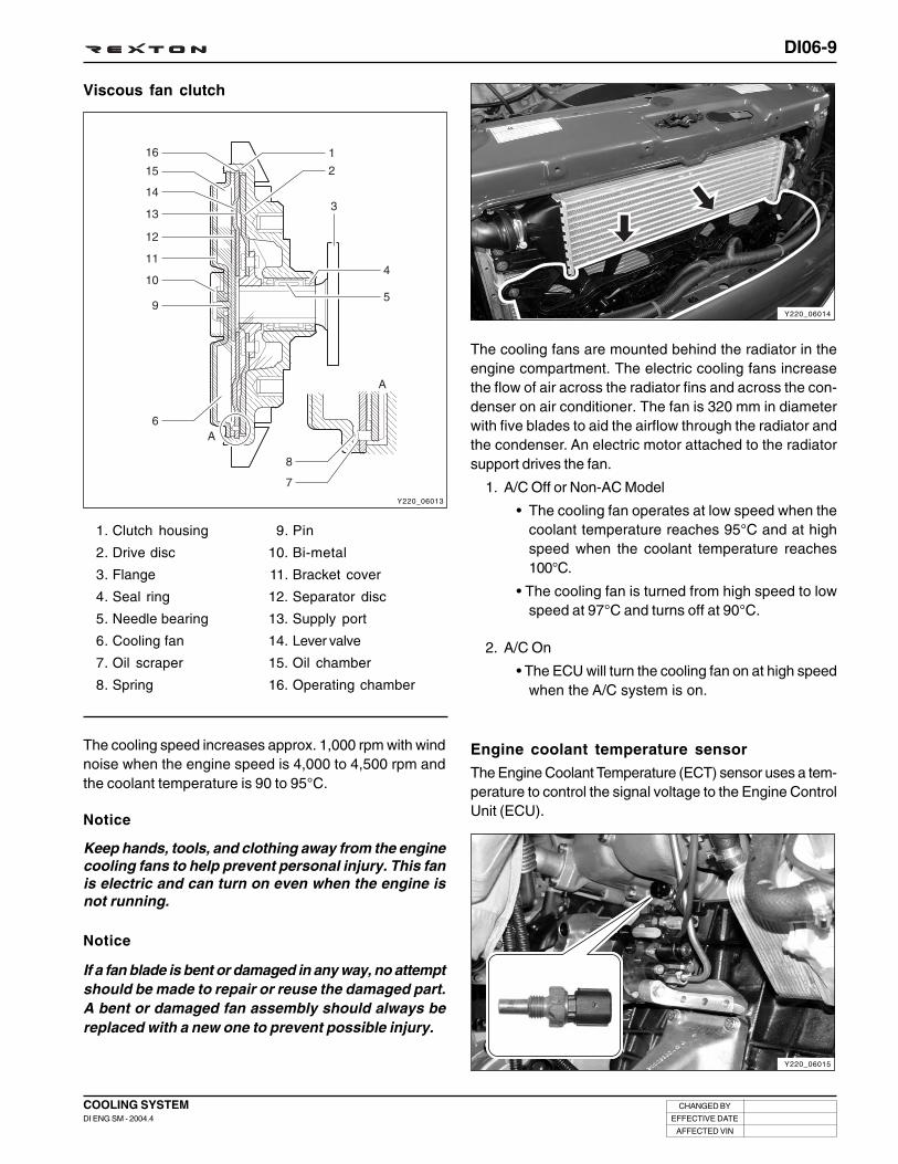
DI06-9
CHANGED BY
EFFECTIVE DATE
AFFECTED VIN
COOLING SYSTEMDI ENG SM - 2004.4
Y220_06013
Viscous fan clutch
1. Clutch housing
2. Drive disc
3. Flange
4. Seal ring
5. Needle bearing
6. Cooling fan
7. Oil scraper
8. Spring
The cooling speed increases approx. 1,000 rpm with windnoise when the engine speed is 4,000 to 4,500 rpm andthe coolant temperature is 90 to 95°C.
The cooling fans are mounted behind the radiator in theengine compartment. The electric cooling fans increasethe flow of air across the radiator fins and across the con-denser on air conditioner. The fan is 320 mm in diameterwith five blades to aid the airflow through the radiator andthe condenser. An electric motor attached to the radiatorsupport drives the fan.
1. A/C Off or Non-AC Model
• The cooling fan operates at low speed when thecoolant temperature reaches 95°C and at highspeed when the coolant temperature reaches100°C.
• The cooling fan is turned from high speed to lowspeed at 97°C and turns off at 90°C.
2. A/C On
• The ECU will turn the cooling fan on at high speedwhen the A/C system is on.
Engine coolant temperature sensor
The Engine Coolant Temperature (ECT) sensor uses a tem-perature to control the signal voltage to the Engine ControlUnit (ECU).
9. Pin
10. Bi-metal
11. Bracket cover
12. Separator disc
13. Supply port
14. Lever valve
15. Oil chamber
16. Operating chamber
Y220_06014
Y220_06015
Notice
Keep hands, tools, and clothing away from the enginecooling fans to help prevent personal injury. This fanis electric and can turn on even when the engine isnot running.
Notice
If a fan blade is bent or damaged in any way, no attemptshould be made to repair or reuse the damaged part.A bent or damaged fan assembly should always bereplaced with a new one to prevent possible injury.

DI06-10
CHANGED BY
EFFECTIVE DATE
AFFECTED VIN
COOLING SYSTEMDI ENG SM - 2004.4
Cooling system
Coolant
Thermostat
Cooling fan
Coolant reservoir
Water pump
Radiator
Coolant tempera-ture sensor
Anti-freeze agent
SPECIFICATIONS
Type
Capacity
Type
Initial opening temperature
Fully opening temperature
Fully closing temperature
Stroke
Type
Blades
Diameter
Low speed ON temp
Low speed OFF temp
High speed ON temp
High speed OFF temp
High speed ON temp. (By A/C pressure)
pressure valve opening pressure
Vacuum valve opening pressure
Type
Impeller diameter
Impeller blades
Type
Core width
Core height
Core thickness
Minimum radiation capability
Resistance (at 20°C)
Resistance (at 80°C)
Type
Mixture ratio (water and anti-freeze)
Description
Water cooling forced circulation
11.3
Wax pellet type
85
80
100
95
83
78
min. 8
min. 8
Electric
5
320 (2)
91
88
95
92
270
1.2 ~ 1.5
0.1
Turbo centrifugal
72.3
10
Down-flow
701
372
18
45,000
3.33 ~ 3.78
0.32 ~ 0.35
ALUTEC-P78
50 : 50
Specification
-
-
°C
°C
°C
°C
°C
°C
mm
mm
-
mm
°C
°C
°C
°C
psi
Kg/cm2
Kg/cm2
-
mm
-
mm
mm
mm
Kcal/h
KΩ
KΩ
−
−
Unit
DI Engine
IDI Engine
DI Engine
IDI Engine
DI Engine
IDI Engine
DI Engine
IDI Engine

DI06-11
CHANGED BY
EFFECTIVE DATE
AFFECTED VIN
COOLING SYSTEMDI ENG SM - 2004.4
Y220_06016
Coolant Level Check
1. Place the vehicle on a level ground and check the coolant level through the coolant reservoir.
2. Add if needed. Change the coolant if necessary.
Notice
• Scalding hot coolant and steam could be blown out under pressure, which could cause serious injury. Neverremove the coolant reservoir cap when the engine and radiator are hot.
• Take precautions to prevent antifreeze coming in contact with the skin, eyes or vehicle body. If contacthappens, rinse affected areas immediately with plenty of water.

DI06-12
CHANGED BY
EFFECTIVE DATE
AFFECTED VIN
COOLING SYSTEMDI ENG SM - 2004.4
Y220_06018
Y220_06017
Coolant Temperature Sensor
Coolant temperature sensor is a NTC resister that sends coolant temperature to ECU.
NTC resister has characteristics that if the engine temperature rises, the resistance lowers so the ECU detects loweringsignal voltages.
If the fuel injected into the engine through injector has more turbulence, then combusts very well. However, if engine tempera-ture is too low, the fuel injected as foggy state forms big compounds causing incomplete combustion. So the sensor detectscoolant temperature and changes coolant temperature changes into voltage then sends to ECU to increase the fuel volumeduring cold start for better starting. And detects engine overheating for fuel volume reduction to protect the engine.
ECU functions as below with coolant temperature sensor signals.
• When engine is cold, controls fuel volume to correct idle speed
• When engine is overheated, controls electrical fan and A/C compressor to protect the engine
• Sends information for emission control
<Coolant Temperature Sensor Circuit>
<Coolant Temperature Sensor> <Output Characteristics of Coolant Temperature Sensor>
Temp.
Resistance
Temperature
20
50
80
120
NTC 2 Resistance ( ΩΩΩΩΩ )
6,062
1,800
638
200
NTC 1 Resistance ( ΩΩΩΩΩ )
2,550
826
321
123
Auto amp
Signal
Ground

DI06-13
CHANGED BY
EFFECTIVE DATE
AFFECTED VIN
COOLING SYSTEMDI ENG SM - 2004.4
• Replace radiator
• Replace coolant reservoir
• Replace heater
• Reconnect hose or replace clamp
• Replace hose
• Replace gasket
• Replace water pump
• Replace water inlet cap gasket
• Replace thermostat sealing
• Retighten
• Replace cylinder head gasket
• Add coolant
• Check coolant concentration
• Repair or replace hose
• Replace thermostat
• Replace water pump
• Replace radiator
• Replace coolant reservoir or cap
• Replace cylinder head or cylinder block
• Clean coolant passages
• Clean radiator core
• Replace cooling fan or repair related circuit
• Replace sensor or repair related circuit
• Replace thermostat
• Replace cooling fan or repair related circuit
• Replace sensor or repair related circuit
Trouble Diagnosis
ActionSymptom
• Leaks in radiator
• Leaks in coolant reservoir
• Leaks in heater core
• Leaks in hose connection
• Damaged coolant hose
• Leaks in water pump gasket
• Leaks in water pump internal seal
• Leaks in coolant inlet cap
• Leaks in thermostat housing
• Improper tightening torque of cylinder head
• Damaged cylinder head gasket
• Coolant leaks (too low coolant level)
• Improper coolant mixture ratio
• Kinked coolant hose
• Defective thermostat
• Defective water pump
• Defective radiator
• Defective coolant reservoir and cap
• Cracks on cylinder head or cylinder block
• Clogged coolant passages in cylinder head or cylinder block
• Clogged radiator core
• Improper operation of cooling fan
• Faulty temperature sensor or defective harness
• Stuck thermostat (with open)
• Improper operation of cooling fan
• Faulty temperature sensor or defective harness
Cause
Excessivelyhigh coolanttemperature
Low coolantlevel
Excessivelylow coolanttemperature

DI06-14
CHANGED BY
EFFECTIVE DATE
AFFECTED VIN
COOLING SYSTEMDI ENG SM - 2004.4
INSPECTION AND REPAIR
Y220_06021
Y220_06020
Y220_06019
2. Add the coolant up to upper mark (arrow) on the reservoir.
3. Install the tester to the coolant reservoir and apply thepressure of 1.4 bar.
4. Check the coolant hoses, pipes and connections for leaksafter the pointer of the tester drops. Replace or retightenas required.
Immerse the thermostat into the water. Heat the water andcheck the valve opening temperature.
Valve opening temperature DI Engine: 85 ± 2°C
Cooling System
1. Release the pressure from coolant reservoir by looseningone notch of coolant reservoir cap, and then remove thecap.
Thermostat
INSPECTION
Notice
Scalding hot coolant and steam could be blown outunder pressure, which could cause serious injury.Never remove the coolant reservoir cap when thebefore the temperature goes down below 90°°°°°C.
Temperature gauge

DI06-15
CHANGED BY
EFFECTIVE DATE
AFFECTED VIN
COOLING SYSTEMDI ENG SM - 2004.4
1. Immerse the senor unit into the water. Heat the waterand check the resistance.
2. If the measured resistance is out of specified value,replace the gauge unit.
3. Measure the resistance between terminal A and gaugeunit housing, and terminal B and gauge unit housing.
1. Immerse the thermostat into the oil. Heat the oil until itreaches the specified temperature and check if thecoolant temperature switch is turned “OFF”.
0.4 Ω / 79°C
23.8 Ω / 115°C
24.8 Ω / -20°C
3.25 Ω / 20°C
Terminal A(for coolant temp.)
Terminal B(for glow plug)
Coolant Temperature Gauge Unit
Thermostat
Y220_06022
Y220_06023
Y220_06024
Notice
Use only engine oil for this inspection. Stir the oilduring heating it. Never heat the oil over requiredtemperature.
113 ± 3°C
116°C
Coolant temperature atpoint A
Coolant temperature atpoint B
Terminal A Terminal B

DI06-16
CHANGED BY
EFFECTIVE DATE
AFFECTED VIN
COOLING SYSTEMDI ENG SM - 2004.4
REMOVAL AND INSTALLATION
Coolant Hose (Inlet/Outlet)
Preceding Work: Draining of coolant
1. Loosen the clamp and remove the coolant outlet hose(engine to radiator).
2. Disconnect the HFM sensor connector.
3. Remove the air intake duct from the air cleaner.
4. Loosen the clamp and remove the coolant inlet hose(radiator to thermostat housing).
Y220_06025
Y220_06026
Y220_06027

DI06-17
CHANGED BY
EFFECTIVE DATE
AFFECTED VIN
COOLING SYSTEMDI ENG SM - 2004.4
Y220_06028
Y220_06029
Y220_06030
Y220_06031
Shroud and Cooling Fan/Clutch
Preceding Works:
- Draining of coolant
- Removal of coolant inlet and outlet hose
- Removal of V-belt
1. Remove the radiator grille.
2. Remove the air intake hoses.
3. Set aside the coolant return pipe.
4. Unscrew the upper bolts and loosen the shroud.
5. Lift up the vehicle and remove the skid plate.
6. Loosen the clamp and remove the lower inlet hose.

DI06-18
CHANGED BY
EFFECTIVE DATE
AFFECTED VIN
COOLING SYSTEMDI ENG SM - 2004.4
6. Remove the shroud.
7. Install in the reverse order of removal.
5. Unscrew the center bolt and remove the cooling fan clutchwhile holding the pulley with counter holder (special tool).
Installation Notice
Y220_06033
Y220_06034
45 ± 4.5 NmTightening torque

DI06-19
CHANGED BY
EFFECTIVE DATE
AFFECTED VIN
COOLING SYSTEMDI ENG SM - 2004.4
Y220_06035
Water Pump - Assembly
Preceding Works:
- Draining of coolant
- Removal of V-belt
- Removal of shroud
- Removal of cooling fan
1. Thermostat housing
2. Gasket ........................................................... Replace
3. Bolt ................................................................... 10 Nm
4. Belt pulley
5. Bolt ................................................................... 10 Nm
6. Water pump
1. Remove the V-belt while pressing down the auto tensioneradjusting bolt.
Y220_06036

DI06-20
CHANGED BY
EFFECTIVE DATE
AFFECTED VIN
COOLING SYSTEMDI ENG SM - 2004.4
2. Unscrew the bolts and remove the EGR pipe and bracket.
Installation Notice
3. Unscrew the bolts and remove the belt pulley whileholding the belt pulley with a special tool.
Installation Notice
4. Remove the oil dipstick tube.
5. Unscrew the bolts and remove the water pump assembly.
Installation Notice
6. Install in the reverse order of removal.
Y220_06037
Y220_06038
Y220_06039
Y220_06040
Tightening torque 23 ± 2.3 Nm
Tightening torque 10 Nm
Tightening torque 10 Nm
Notice
• Replace the O-ring in oil dipstick with new one.
• Plug the oil dipstick hole with a cap not to get theforeign materials into the engine.
Notice
Remove the gasket residues from the sealing surfaceand replace the gasket with new one.

DI06-21
CHANGED BY
EFFECTIVE DATE
AFFECTED VIN
COOLING SYSTEMDI ENG SM - 2004.4
Y220_06041
* Preceding Works:
- Draining of coolant- Removal of V-belt- Removal of cooling fan- Removal of intake duct (air cleaner to turbo charger)
1. Gasket ......................................................Replace
2. Water pump housing
3. Connector
4. Bolt ............................................................. 10 Nm
5. Thermostat
6. Seal
7. Coolant hose
Thermostat

DI06-22
CHANGED BY
EFFECTIVE DATE
AFFECTED VIN
COOLING SYSTEMDI ENG SM - 2004.4
1. Unscrew the bolts and remove the thermostat housing.
Installation Notice
2. Remove the thermostat.
3. Install in the reverse order of removal.
Tightening torque 10 ± 1.0 Nm
Y220_06042
Y220_06043

DI06-23
CHANGED BY
EFFECTIVE DATE
AFFECTED VIN
COOLING SYSTEMDI ENG SM - 2004.4
Water Pump Housing
Preceding Works:
- Removal of water pump assembly
- Removal of thermostat assembly
1. Remove the heater hose.
2. Unscrew the bolts and remove the alternator.
Installation Notice
3. Unscrew the bolts and remove the alternator bracket.
Installation Notice
4. Unscrew the bolts and remove the water pump housing.
Installation Notice
Y220_06044
Y220_06045
Y220_06046
Y220_06047
Notice
• Be careful not to damage the O-ring in coolant outletpipe (cylinder head side).
• Remove the gasket residues from the sealingsurface and replace the gasket with new one.
5. Install in the reverse order of removal.
Tightening torque 25 ± 2.5 Nm
Tightening torque 10 ± 1.0 Nm
Tightening torque 46 ± 4.6 Nm

DI06-24
CHANGED BY
EFFECTIVE DATE
AFFECTED VIN
COOLING SYSTEMDI ENG SM - 2004.4
Radiator
Preceding Work: Draining of coolant
1. Lift up the vehicle and remove the skid plate.
2. Remove the clips and washers from bottom of radiator atboth sides.
3. Unscrew the bracket mounting bolts under the radiatorcondenser.
Installation Notice
4. Disconnect the oil inlet and outlet hoses from bottom ofradiator.
Y220_06048
Y220_06049
Y220_06050
Y220_06051
Notice
Be careful not to damage the rubber bushing.
Notice
• Plug the radiator oil holes with caps.
• Replace the hose washers with new ones.
Tightening torque 10 ± 1.0 Nm

DI06-25
CHANGED BY
EFFECTIVE DATE
AFFECTED VIN
COOLING SYSTEMDI ENG SM - 2004.4
Y220_06052
Y220_06053
Y220_06054
Y220_06055
5. Remove the coolant outlet hose.
6. Remove the radiator grille.
7. Remove the coolant inlet hose and the cooler inlet hose.
8. Remove the coolant return hose.
9. Unscrew the bolts and remove the shroud.

DI06-26
CHANGED BY
EFFECTIVE DATE
AFFECTED VIN
COOLING SYSTEMDI ENG SM - 2004.4
10. Unscrew the bolts and remove the radiator upper plate.
Installation Notice
11. Unscrew the bracket mounting bolts on the radiatorcondenser.
Installation Notice
12. Remove the radiator by pulling it up carefully.
13. Install in the reverse order of removal.
Y220_06056
Y220_06057
Y220_06058
Tightening torque 10 ± 1.0 Nm
Tightening torque 10 ± 1.0 Nm

DI06-27
CHANGED BY
EFFECTIVE DATE
AFFECTED VIN
COOLING SYSTEMDI ENG SM - 2004.4
1. Drain the coolant.
2. Remove the hoses.
4. Install in the reverse order of removal.
3. Unscrew the bolts and remove the coolant reservoir.
Installation Notice
Coolant Reservoir
Y220_06059
Y220_06060
Tightening torque 7 Nm

DI06-28
CHANGED BY
EFFECTIVE DATE
AFFECTED VIN
COOLING SYSTEMDI ENG SM - 2004.4
3. Remove the drain plug (1) and seal (2) in the cylinderblock and drain the coolant.
4. Replace the seal with new one and install the drain plug.
Installation Notice
5. Install the drain plug in bottom of radiator.
6. Add the coolant through the coolant reservoir.
7. Warm up the engine until the thermostat begins to openand check if the coolant level is at “FULL” mark on thereservoir. Add if necessary.
2. Loosen the drain plug in bottom of radiator and drain thecoolant.
1. Release the pressure from coolant reservoir by looseningone notch of coolant reservoir cap, and then remove thecap.
Draining and Adding of Coolant
Y220_06062
Y220_06063
Tightening torque 30 Nm
Notice
Scalding hot coolant and steam could be blown outunder pressure, which could cause serious injury.Never remove the coolant reservoir cap when thebefore the temperature goes down below 90°C.
Notice
Collect the drained coolant with a proper container.
Notice
• Keep the coolant mixture ratio of 50:50 (water : anti-freezer).
• Add the coolant until the water flows out throughthe overflow hose.
Y220_06061

DI06-29
CHANGED BY
EFFECTIVE DATE
AFFECTED VIN
COOLING SYSTEMDI ENG SM - 2004.4
Y220_06068
PREHEATING SYSTEM
Preheating relayGlow plug
ECU Glow indicator (meter cluster)

DI06-30
CHANGED BY
EFFECTIVE DATE
AFFECTED VIN
COOLING SYSTEMDI ENG SM - 2004.4
KR/Y
Y220_06069
OVERVIEWGlow plug is installed on the cylinder head (combustion chamber) in the D27DT preheating control unit system. Coldstarting performance has improved and exhaust gas during cold starting has reduced.
ECU receives coolant temperature and engine speed to control; after monitoring the engine preheating/after heating andglow plug diagnosis function, the fault contents will be delivered to ECU.
• Engine preheating/after heating functions
• Preheating relay activation by ECU controls
- Senses engine temperature and controls the preheating/after heating time
- Glow indicator
• K-LINE for information exchanges between preheating unit and ECU
- Transmits preheating unit self-diagnosis results to ECU
- Transmits glow plug diagnosis results and operating status to ECU
PREHEATING RELAY
Structure
K-LINE #1(ECU 34)
IG1Power terminal
Glow plugcontrol signal
(ECU 113)
Ground terminal
B+main wire(12V)STICS terminal
(remote start)Glow plugterminal

DI06-31
CHANGED BY
EFFECTIVE DATE
AFFECTED VIN
COOLING SYSTEMDI ENG SM - 2004.4
Y220_06070
PREHEATING SYSTEM DIAGRAM
Specifications
Description
Rated voltage
Operating voltage range
Operating range
Relay operating voltage
Relay releasing voltage
Relay coil resistance
Voltage drop
Parasitic current
Specification
DC 12 V
DC 8 ~ 15 V
- 40 ~ + 100°C
Over 6.5 V
Over 1.5 V
11.3 Ω
Below 150 mV at each glow plug (at 16A of current)
MAX 1mA
STICS(remote start)
Coolanttemperature
sensor

DI06-32
CHANGED BY
EFFECTIVE DATE
AFFECTED VIN
COOLING SYSTEMDI ENG SM - 2004.4
FunctionPreheating system controls and checks following functions and operating conditions.
Pre-Heating
• The power will be supplied to the glow plugs by ECU controls when the power is supplied to the IG terminal fromthe battery and there are normal communications with ECU within 2 seconds. The surface of glow plug will beheated up to 850°C very quickly to aid combustion by vaporizing air-fuel mixture during compression stroke.
• Preheating time is controlled by ECU.
After-heating
• When the engine is started, after-heating starts by ECU controls. The idle rpm will be increased to reduce toxicsmoke, pollutants and noises.
• After-heating time is controlled by ECU.
Checking glow plugs
• Check each glow plug for short in circuit
• Check each glow plug for open in circuit due to overvoltage
• Check glow plug for short to ground
Forceful relay shut-down
• When glow plug is shorted to ground
K-Line communication
• ECU sends the results to preheating time control relay through K-Line to start communication.
• Preheating time control relay sends messages including self-diagnosis data for glow plugs to ECU.
• Glow plug makes communication only as response to demand.
• When power is supplied, ECU starts self-diagnosis within 2 seconds.
• Under the following conditions, communication error occurs.
- When there is no response from glow plug module within 2 seconds
- When an error is detected in checksum
- Less byte is received
Error code of “P1720 - Pre heating control communication fail” will be reported.
Operating time
Pre-
heating
Coolant Temp.
Operating Time
• IG: “ON”
• B+ : below 15.2V
ReleaseConditions
• After operating time elapsed
• IG: “OFF” • When engine cranking
• After engine startingAfter-
heating
Glow
Indicator
-35 °C -25 °C -20 °C -10 °C 0 °C 10 °C 20 °C
Coolant Temp.
Operating Time
Coolant Temp.
Operating Time
• After operating time elapsed
• Torque : 190/170 Nm
• Speed: 2100/2050 rpm
• When engine cranking
ReleaseConditions
• IG: “ON”
31 sec 22 sec 19 sec 17 sec 14 sec 0 sec 0 sec
-30 °C
115 sec
-30 °C
18 sec
-20 °C
80 sec
-25 °C
16 sec
-10 °C
30 sec
-20 °C
10 sec
0 °C
19 sec
-10 °C
5 sec
10 °C
11 sec
0 °C
2 sec
20 °C
11 sec
10 °C
0 sec
35 °C
0 sec
20 °C
0 sec
OperatingConditions
OperatingConditions
OperatingConditions
ReleaseConditions
FUEL SYSTEM
SECTION DI07

DI07-1
CHANGED BY
EFFECTIVE DATE
AFFECTED VIN
FUEL SYSTEMDI ENG SM - 2004.4
FUEL SYSTEM
00SECTION DI07
Table of Contents
CAUTIONS FOR DI ENGINE....................................... DI07-3
FUEL SYSTEM ............................................................ DI07-6
Fuel injection system .............................................. DI07-6
Fuel transfer line ................................................... DI07-12
Inlet metering valve (IMV) ..................................... DI07-14
High fuel pressure line .......................................... DI07-17
Injector .................................................................. DI07-48


DI07-3
CHANGED BY
EFFECTIVE DATE
AFFECTED VIN
FUEL SYSTEMDI ENG SM - 2004.4
CAUTIONS FOR DI ENGINE
Water Separator Warning Light
This chapter describes the cautions for DI engine equipped vehicle. This includes the water separation from engine,warning lights, symptoms when engine malfunctioning, causes and actions.
When the water level inside water sepa-rator in fuel filter exceeds a certain level(approx. 39 cc), this warning lightcomes on and buzzer sounds.
Also, the driving force of the vehicledecreases (torque reduction). If theseconditions occur, immediately drainthe water from fuel filter.
For the draining procedures, please re-fer to “How to drain the water from fuelfilter” section.
DI EngineComparatively conventional diesel engines, DI engine con-trols the fuel injection and timing electrically, delivers highpower and reduces less emission.
System Safety ModeWhen a severe failure has been occurred in a vehicle, thesystem safety mode is activated to protect the system. Itreduces the driving force, restricts the engine speed (rpm)and stops engine operation. Refer to “Diagnosis” sectionin this manual.

DI07-4
CHANGED BY
EFFECTIVE DATE
AFFECTED VIN
FUEL SYSTEMDI ENG SM - 2004.4
Priming PumpThe priming pump installed in fuel pump is the device to fill the fuel into the fuel filter. When the vehicle is under theconditions as below, press the priming pump until it becomes rigid before starting the engine.
Y220_07003
1. Fuel filter
3. Priming pump
Notice
• When replaced the fuel filter or drained the water from fuel filter, press the priming pump until it becomesrigid before starting the engine.
• The water drain from fuel filter should be performed whenever changing the engine oil.
2. Water drain plug
(to be drained every 15,000km max.)
Draining could be done at same time than oil
change
Conditions for using Priming Pump1. After run out of fuel
2. After draining the water from fuel separator
3. After replacing filter or any intervention on system
Fuel Filter and Water Separator
WARNING
Never reverse filter or use it in other place (clean side)

DI07-5
CHANGED BY
EFFECTIVE DATE
AFFECTED VIN
FUEL SYSTEMDI ENG SM - 2004.4
Draining the Water From Fuel Filter1. Place the water container under the fuel filter.
2. Turn the drain plug (2) to “A” direction to drain the water.
3. Press priming pump until all water is drained, then turnthe drain plug to “B” direction to tighten it.
Notice
Be careful not to be injured by surroundingequipment during the working procedures.
4. Press the priming pump until it becomes rigid.
5. Start the engine and check the conditions.
6. Clear the fault code of ECU with scan 100.
WARNING
If the priming pump is not properly operated, air mayget into the fuel line. It may cause starting problemor fuel system problem. Make sure to perform thejob in step 4.
Y220_07004
Y220_07005
Y220_07006

DI07-6
CHANGED BY
EFFECTIVE DATE
AFFECTED VIN
FUEL SYSTEMDI ENG SM - 2004.4
Y220_07007
FUEL SYSTEM
According to input signals from various sensors, engine ECU calculates driver’s demand (position of the acceleratorpedal) and then controls overall operating performance of engine and vehicle on that time.
ECU receives signals from sensors via data line and then performs effective engine air-fuel ratio controls based on thosesignals. Engine speed is measured by crankshaft speed (position) sensor and camshaft speed (position) sensor deter-mines injection order and ECU detects driver’s pedal position (driver’s demand) through electrical signal that is gener-ated by variable resistance changes in accelerator pedal sensor. Air flow (hot film) sensor detects intake air volume andsends the signals to ECU. Especially, the engine ECU controls the air-fuel ratio by recognizing instant air volumechanges from air flow sensor to decrease the emissions (EGR valve control). Furthermore, ECU uses signals fromcoolant temperature sensor and air temperature sensor, booster pressure sensor and atmospheric pressure sensor ascompensation signal to respond to injection starting, pilot injection set values, various operations and variables.
FUEL INJECTION SYSTEM
Electronic Control of Fuel System
Supply lineReturn lineECU connecting line
Fuel pressure sensor
Common rail
Injectionpipe
Injectors
Sensors
HFM sensor
Cam position sensor
Crankshaft position sensor
Knock sensor, etc.ECUFuel tank
Fuel filterPrimingpump
Water separator
IMV valve
Low and highpressure pump
Fuel temperaturesensor
High pressure pump
System composition
- Fuel pressure sensor
- Other sensors and actuators
- High pressure fuel pump
- Fuel injector
- Fuel rail
- Electronic control unit (ECU)
Water detectionsensor

DI07-7
CHANGED BY
EFFECTIVE DATE
AFFECTED VIN
FUEL SYSTEMDI ENG SM - 2004.4
Y220_07008
Composition of Fuel SystemComponents in fuel system are designed to generate and distribute high pressure, and they are controlled electronicallyby engine ECU. Accordingly, fuel system is completely different from injection pump type fuel supply system on theconventional Diesel engine. The fuel injection system in common rail engine is composed of transfer pressure sectionthat transfers fuel in low pressure, high pressure section that transfers fuel in high pressure and ECU control section.
Fuel route
High pressure pipe
Common rail
Fuel pressure sensor
Fuel filter
Priming pump
Fuel pump(High pressure pump, transfer pump)
Injector
<Fuel line system>
Fuel tank Priming pump Fuel filterTransfer
pump
Injector Common railHigh pressure
pumpFuel pressure
regulation valve
Transfer pressure line
High pressure line
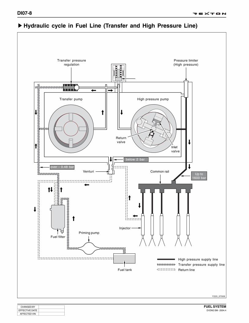
DI07-8
CHANGED BY
EFFECTIVE DATE
AFFECTED VIN
FUEL SYSTEMDI ENG SM - 2004.4
Y220_07009
Hydraulic cycle in Fuel Line (Transfer and High Pressure Line)
Transfer pressureregulation
Pressure limiter(High pressure)
High pressure pumpTransfer pump
Returnvalve
Inletvalve
Venturi
Fuel filterPriming pump
Fuel tank
Injector
Common rail
High pressure supply line
Transfer pressure supply line
Return line
over - 0.48 bar
below 2 bar
Up to1600 bar

DI07-9
CHANGED BY
EFFECTIVE DATE
AFFECTED VIN
FUEL SYSTEMDI ENG SM - 2004.4
Y220_07012
Components of Low Pressure Transfer LineLow pressure stage is to supply sufficient fuel to high pressure section and components are as below.
• Fuel tank (including strainer)
• Hand priming pump
• Fuel filter
• Transfer pump
• Other low pressure fuel hoses
Y220_07010
Y220_07011
Fuel tank
Fuel tank is made of anti-corrosion material and its allowablepressure is 2 times of operating pressure (more than 0.3 bar).It has protective cap and safety valve to prevent excessivepressure building. Also, it has structure to prevent fuel fromleaking in shocks, slopes and corners and to supply fuelsmoothly.
Priming pumpIf fuel runs out during driving or air gets into fuel line after fuelfilter replacement, it may cause poor engine starting or dam-age to each component. Therefore, the hand priming pump isinstalled to bleed air from transfer line.When the vehicle is under the conditions as below, press thepriming pump until it becomes rigid before starting the engine.
- After run out of fuel- After draining the water from fuel filter- After replacing the fuel filter
Press the priming pump until it becomes rigid before startingthe engine.
Fuel filter
It requires more purified fuel supply than conventional dieselengine. If there are foreign materials in the fuel, fuel systemincluding pump components, delivery valve and injector nozzlesmay be damaged.
Fuel filter purifies fuel before it reaches to high pressure pumpto help proper operations in high pressure pump. And more, itseparates water from fuel to prevent water from getting intoFIE system (high pressure line).

DI07-10
CHANGED BY
EFFECTIVE DATE
AFFECTED VIN
FUEL SYSTEMDI ENG SM - 2004.4
Components of High Pressure Transfer LineIn the high pressure section, sufficient fuel pressure that injectors requires will be generated and stored. The compo-nents are as below:
• High pressure pump
• Rail pressure sensor
• Pressure limit valve
• Common rail
• High pressure pipe
• Injector
• Fuel pressure regulating valve (IMV)
High pressure pump (including IMV and limit valve)
This is plunger pump that generates high pressure; and drivenby crankshaft with timing chain. The high pressure pump in-creases system pressure of fuel to approx. 1,600 bar and thiscompressed fuel is transferred to high pressure accumulator(common rail) in tube through high pressure line.
Common rail (including pressure sensor)
It stores fuel transferred from high pressure pump and alsostores actual high pressure of fuel. Even though the injectorsinject fuel from the rail, the fuel pressure in the rail is main-tained to a specific value. It is because the effect of accumu-lator is increased by unique elasticity of fuel. Fuel pressure ismeasured by rail pressure sensor. And the inlet metering valve(IMV) included in high pressure pump housing keeps pres-sure to a desired level.
Y220_07015
Y220_07014
Y220_07013
High pressure pipe (fuel pipe)
Fuel line transfers high pressure fuel. Accordingly, it is madeof steel to endure intermittent high frequency pressure changesthat occur under maximum system pressure and injectionstops. Injection lines between rail and injectors are all in thesame length; it means the lengths between the rail and eachinjector are the same and the differences in length are com-pensated by each bending.
No.1 and 3 cylinder No. 5 cylinder
No.2 and 4 cylinder

DI07-11
CHANGED BY
EFFECTIVE DATE
AFFECTED VIN
FUEL SYSTEMDI ENG SM - 2004.4
Fuel Filter Replacement
* Fuel filter change interval: every 30,000 km
* Water separation interval: every 15,000 km max. (same with engine oil change interval)
* Never reuse the removed fuel filter
Y220_07016
Y220_07017
InjectorsThe fuel injection device is composed of electrical solenoidvalve, needle and nozzle and controlled by engine ECU. Theinjector nozzle opens when solenoid valve is activated to di-rectly inject the fuel into combustion chamber in engine. Wheninjector nozzle is open, remaining fuel after injection returnsto fuel tank through return line.
Transfer pump
The transfer pump is included in the housing of the high pres-sure pump. The transfer pump is the volumetric blade typepump. To deliver the continuously required fuel volume, thepump transfers fuel from the fuel tank to high pressure pump.

DI07-12
CHANGED BY
EFFECTIVE DATE
AFFECTED VIN
FUEL SYSTEMDI ENG SM - 2004.4
<Sectional view of transfer pump>
Y220_07018
FUEL TRANSFER LINE
Transfer Pump
DescriptionThe transfer pump is the device to provide sufficient fuel to high fuel pressure line and is mechanical type feed pump thatis driven by timing chain linked to crankshaft. This mechanical type feed pump is subject to air inflow, therefore, a handpriming pump is installed to fill fuel in Low fuel pressure(LP) circuit.
The transfer pump is included in the housing of the HP pump. The transfer pump is the volumetric blade type pump andconsists of the following components:
• A rotor turned by the shaft of the HP pump. The connection is provided by splines.
• An eccentric liner fixed to the housing of the HP pump by 6 Torx bolts. The liner is positioned by two off-set pins inorder to prevent any assembly errors.
• Four blades set at 90°. Each blade is held against the liner by a coil spring.
• The inlet and outlet orifice.
HP pump
<Sectional view of fuel pump>
Transfer pump

DI07-13
CHANGED BY
EFFECTIVE DATE
AFFECTED VIN
FUEL SYSTEMDI ENG SM - 2004.4
Y220_07026
Y220_07025
Principle of operation
Consider the chamber between the rotor, the liner and two successive blades (refer to above figure).
• When the chamber is in position 1, the volume of the chamber is minimal. The changes in volume according to theangle of rotation of the rotor are small.
• The rotor makes a quarter turn clockwise. The previous chamber is now in position 2.
The inlet orifice is uncovered. The volume contained in the chamber quickly rises. The pressure inside the chamberdrops sharply. Fuel is drawn into the chamber.
• The rotor continues to rotate. It is now in position 3. The inlet and outlet orifices are now sealed off. The volume areacontrolled by the rotor, the liner and the two blades is at the maximum. The changes in volume according to theangle of rotation of the rotor are small.
• The rotor continues to rotate. It is finally in position 4. The outlet orifice is uncovered. The volume area controlled bythe rotor, the liner and the blades decreases quickly. The pressure inside the chamber rises sharply. The fuel isexpelled under pressure. The depression caused by the transfer pump’s rotation is sufficient to draw in diesel fuelthrough the filter. The transfer pump is driven by the shaft of the HP pump, transfer pressure thus rises with enginespeed. A regulating valve allows the transfer pressure to be maintained at a practically constant level (about 6 bar)throughout the whole range of engine operations by returning some of the fuel to the pump inlet.
Regulating pressure
Volume controlled
Flow
Intake capacity
6 bar
5.6 cm3/revolution
90 /h at 300 rpm pump
650 /h at 2,500 rpm pump
65 mbar at 100 rpm pump
Characteristics of the transfer pump
Fuel pump speed (rpm)
Fuelpressure
(bar)
Housing Rotor
Chamber
Blade

DI07-14
CHANGED BY
EFFECTIVE DATE
AFFECTED VIN
FUEL SYSTEMDI ENG SM - 2004.4
INLET METERING VALVE (IMV)
Y220_07027
Y220_07028
Y220_07029
Overview
The LP actuator, also called the inlet metering valve, is usedto control the rail pressure by regulating the amount of fuelwhich is sent to the pumping element of the HP pump.
This actuator has two purposes:
1. Firstly, it allows the efficiency of the injection system tobe improved, since the HP pump only compresses theamount of fuel necessary to maintain in the rail the levelof pressure required by the system as a function of theengine’s operating conditions.
2. Secondary, it allows the temperature to be reduced inthe fuel tank. When the excess fuel is discharged intothe back leak circuit, the pressure reduction in the fluid(from rail pressure down to atmospheric pressure) givesoff a large amount of heat. This leads to a temperaturerise in the fuel entering the tank. In order to prevent toohigh a temperature being reached, it is necessary to limitthe amount of heat generated by the fuel pressurereduction, by reducing the back leak flow. To reduce theback leak flow, it is sufficient to adapt the flow of the HPpump to the engine’s requirements throughout itsoperating range.
IMV effect
without IMVwith IMV
without IMVwith IMV
Fuel temperature atsystem backleak
Fu
el T
em
p.(
°C)
Torque (Nm)
Torque (Nm)
Rail pressure = 80 bar

DI07-15
CHANGED BY
EFFECTIVE DATE
AFFECTED VIN
FUEL SYSTEMDI ENG SM - 2004.4
Y220_07019
Composition of IMVThe IMV is located on the hydraulic head of the pump. It is fed with fuel by the transfer pump via two radial holes. Acylindrical filter is fitted over the feed orifices of the IMV. This makes it possible to protect not only the LP actuator, butalso all the components of the injection system located downstream of the IMV.
The IMV consists of the following components:
• A piston held in the fully open position by a spring.
• A piston filter located at inlet.
• Two O-rings ensuring pressure tightness between the hydraulic head and the body of the IMV.
• A body provided with two radial inlet holes and an axial outlet hole.
• Coil
Filter
High pressure
Outlet hole O-ring
Fuel
Transfer pump
Transfer pump Solenoid
Fuel
Spring
Piston

DI07-16
CHANGED BY
EFFECTIVE DATE
AFFECTED VIN
FUEL SYSTEMDI ENG SM - 2004.4
Y220_07020
Principle of OperationThe LP actuator is used to proportion the amount of fuel sent to the pumping element of the HP pump in such a way thatthe pressure measured by the HP sensor is equal to the pressure demand sent out by the ECU. At each point ofoperation, it is necessary to have:
• Flow introduced into the HP pump = Injected flow + Injector backleak flow + injector control flow
The IMV is normally open when it is not being supplied with fuel. It cannot therefore be used as a safety device to shutdown the engine if required.
The IMV is controlled by current. The flow/current law is represented below.
• Engine speed
• Flow demand
• Rail pressure demand
• Measured rail pressure
E
C
U
• Inlet MeteringValve (IMV)
Piston stroke
Diameter of holes
Coil resistance
Power supply
Max. current
Weight
Operating temperature
Fluid temperature
Control logic
1.4 mm
3.4 mm
5.4 Ω (at 25°C)
Battery voltage (It is prohibited to supply the IMV directly at the battery voltageduring the diagnostic test)
1 A
260 g
40°C < T < 125°C
40°C < T < 90°C
Normally open without power (The flow decreases as the current rises).
• ECU determines the value of the current to be sent to the IMV according to:
Specifications
Flo
w (
I/h
r)
Flow / Current Law
Current (mA)

DI07-17
CHANGED BY
EFFECTIVE DATE
AFFECTED VIN
FUEL SYSTEMDI ENG SM - 2004.4
Y220_07021
HIGH FUEL PRESSURE LINE
High Pressure Pump
DescriptionThis pump generates high fuel pressure and is driven by timing chain (radial plunger principle). This pump pressurizesthe fuel to approx. 1600 bar and sends this high pressurized fuel to high pressure accumulator (common rail) via highpressure line.
It is possible to extend the pumping phase in order to considerably reduce drive torque, vibration and noise since the pump nolonger determines the injection period. The differences from conventional rotary pumps lies in the fact that it is no longer thehydraulic head rotor which turns inside the cam, but the cam which turns around the hydraulic head. Thus, any problems ofdynamic pressure tightness are eliminated because the high pressure is generated in the fixed part of the pump.
Specifications
• Maximum operating pressure: 1600 ± 150 bar
• Max. Overpressure: 2100 bar
• Maximum sealing pressure: when using a plug instead of PRV, no leaks around pump outlet port (when applying2500 bar of constant pressure)
• Operating temperature: Continuously operating within temperature range of -30°C ~ 120°C in engine compartment
• Inflowing fuel temperature: The maximum inflowing fuel temperature is 85°C (continuously able to operate)
• Pump inlet pressure: Relative pressure Min. - 0.48 bar (to end of filter’s lifetime)
• Driving torque: 15 Nm / 1600 bar
• Gear ratio (engine: pump): 0.625
• Lubrication: - Inside lubrication (rear bearing): Fuel
- Outside lubrication (front bearing): Engine oil
1. IMV (Inlet Metering Valve)
2. Hydraulic Head
3. Plunger
4. Drive shaft and cam ring
5. Housing
6. Roller and shoe
7. Transfer pump
8. Fuel temperature sensor
9. High fuel pressure - OUT
10. Pressure regulator
Fuel supply
Fueldischarge

DI07-18
CHANGED BY
EFFECTIVE DATE
AFFECTED VIN
FUEL SYSTEMDI ENG SM - 2004.4
<Pressurize>Y220_07022
Principle of operation• During the filling phase, the rollers are kept in contact with the cam by means of coil springs mounted on either side
of each shoe. The transfer pressure is sufficient to open the inlet valve and to move the pumping plungers apart.Thus, the dead volume between the two plungers fills with fuel.
• When the diametrically opposite rollers simultaneously encounter the leading edge of the cam, the plungers arepushed towards each other.
• As soon as the pressure becomes higher than the transfer pressure, the inlet valve closes. When the pressurebecomes higher than the pressure inside the rail, the delivery valve opens. Consequently, the fuel is pumped underpressure into the rail.
• During the input phase, transfer pressure pushes back the inlet valve. Fuel enters the body of the pumping element.The valve closes as soon as the pressure in the pumping element becomes higher than the transfer pressure.
• During the input phase, the ball of the delivery valve is subject to the rail pressure on its outer face and to the transferpressure on its inner face. Thus the ball rests on its seat, ensuring the pressure tightness of the body of the pumpingelement. When the pressure in the element becomes higher than the pressure in the rail, the ball is unbalanced andit opens. Fuel is then pumped into the rail at high pressure.
This high pressure pump generates the driving torque with low peak torque to maintain the stress to driving components.This torque is smaller than that of conventional injection pump, thus, only a small load will be applied to pump. Therequired power to drive pump is determined by set pressure for rail and pump speed (delivery flow). Note that the fuelleakage or defective pressure control valve may affect the engine output.
<Fuel input>
Roller
Plunger

DI07-19
CHANGED BY
EFFECTIVE DATE
AFFECTED VIN
FUEL SYSTEMDI ENG SM - 2004.4
<Inlet valve> <Delivery valve>Y220_07023
Inlet valve and delivery valveDuring the input phase, transfer pressure pushes back the inlet valve. Fuel enters the body of the pumping element.Under the effect of the transfer pressure, the two plungers are forced apart. When the rollers simultaneously encounterthe leading edge of the cam, pressure suddenly rises in the body. Of the pumping element. The valve closes as soon asthe pressure in the pumping element becomes higher than the transfer pressure. During the input phase, the ball of thedelivery valve is subject to the rail pressure on its outer face and to the transfer pressure on its inner face. Thus the ballrests on its seat, ensuring the pressure tightness of the body of the pumping element. When the two diametricallyopposite rollers encounter the leading edges of the cam, the plungers are forced together and pressure quickly rises inthe body of the pumping element. When the pressure in the element becomes higher than the pressure in the rail, theball is unbalanced and it opens. The spring calibration is negligible compared with the pressure forces. Fuel is thenpumped into the rail at high pressure.
Lubrication and cooling of the HP pump
Lubrication and cooling of the pump are provided by the fuel circulation. The minimum flow required to ensure adequateoperation of the pump is 50 /h.
Phasing of HP pump required and offer 2 advantages
Conventional fuel injection pumps ensure pressurizing and distribution of the fuel to the different injectors. It is essentialto set the pump in such a way that the injection occurs at the required place during the cycle. The HP pump of thecommon rail system is no longer used for the fuel distribution, it is therefore not necessary to set the pump in relationto the engine.
Nevertheless, the setting or phasing of the pump offers two advantages:
• It allows the torque variations of the camshaft and the pump to be synchronized in order to reduce the stresses onthe timing belt.
• It allows pressure control to be improved by synchronizing peak pressures produced by the pump with pressure-drops caused by each injection.
This phasing allows pressure stability to be improved, which helps to reduce the difference in flow between the cylinders.

DI07-20
CHANGED BY
EFFECTIVE DATE
AFFECTED VIN
FUEL SYSTEMDI ENG SM - 2004.4
Y220_07024
HP Pump Fuel RouteThe fuel passed through the fuel filter is sent to the transfer pump via the HP inlet pump. this fuel passes through thetransfer pump by the transferring pressure and maintains the predefined value by the regulating valve in HP pump.
Also, this fuel gets into the IMV that controls only the fuel to the high pressure pump.
The below figure describes the pump operations when acceleration and deceleration.
When need high fuel pressure (acceleration)
Transfer pump High pressure pump
IMV open
Venturi
to common rail
to fuel tank
Backleak
Fuel supply

DI07-21
CHANGED BY
EFFECTIVE DATE
AFFECTED VIN
FUEL SYSTEMDI ENG SM - 2004.4
<Pressure curve of HP pump>Y220_07031
When do not need high fuel pressure (deceleration)
Y220_07030
The fuel is sent to the high pressure side (hydraulic head) and compressed by the plunger. And, goes into the commonrail through the high pressure pipe.
The IMV installed in the high pressure side (hydraulic head) of HP pump precisely controls the fuel amount and deliversthe rail pressure feedback same as required amount.
The IMV is controlled by ECU.
Performance curve of HP pumpThe time required to obtain a sufficient pressure in the rail to enable the engine to start depends on the volume of thesystem (definition of the rail, length of the pipes, etc.). The aim is to reach a pressure of 200 bars in 1.5 revolutions (3rdcompression).
• Maximum operating pressure: 1600 ± 150 bar
IMV close
Venturi
to common rail
to fuel tank
Backleak
Fuel supply
Transfer pump High pressure pump
Ra
il p
ress
ure
(b
ar)
Engine speed (rpm)
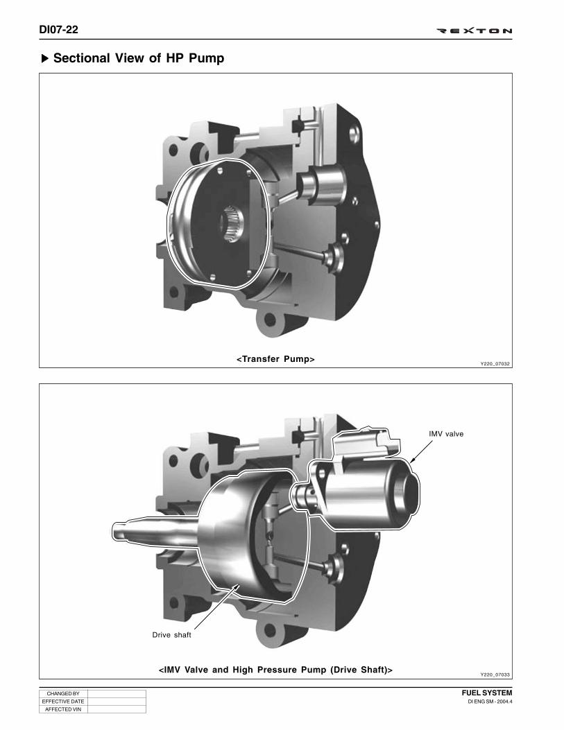
DI07-22
CHANGED BY
EFFECTIVE DATE
AFFECTED VIN
FUEL SYSTEMDI ENG SM - 2004.4
<Transfer Pump>
<IMV Valve and High Pressure Pump (Drive Shaft)>
Sectional View of HP Pump
Y220_07032
Y220_07033
IMV valve
Drive shaft

DI07-23
CHANGED BY
EFFECTIVE DATE
AFFECTED VIN
FUEL SYSTEMDI ENG SM - 2004.4
<Inlet Valve, Outlet Valve, Shoe and Roller, Temperature Sensor>
<Hydraulic Head>
Y220_07034
Y220_07035
Inlet valve
Temperature sensor
Supply valveShoe and roller

DI07-24
CHANGED BY
EFFECTIVE DATE
AFFECTED VIN
FUEL SYSTEMDI ENG SM - 2004.4
Removal
Preceding Works
- Disconnection of negative battery cable
- Removal of engine cover
The trouble diagnosis should be performed before removing the HP pump. Refer to “Diagnosis” section.
1. Remove the bolts on the fan shroud. Disconnect the airintake duct from intake manifold and the coolant outletport connecting hose.
2. Remove the fan belt while pressing down the autotensioner adjusting bolt.
3. Unscrew the center bolt and remove the cooling fan clutchwhile holding the pulley with counter holder (special tool).
Y220_07036
Y220_07037
Y220_07038
Notice
Plug the coolant port not to get the coolant into theengine. Add the coolant as required when installing.
4. Remove the fan shroud and fan clutch simultaneously.
Tightening torque 45 ± 4.5 Nm

DI07-25
CHANGED BY
EFFECTIVE DATE
AFFECTED VIN
FUEL SYSTEMDI ENG SM - 2004.4
Y220_07039
Y220_07040
Y220_07041
Y220_07042
8. Unscrew the bolts and remove the cooling fan bracket(timing chain cover side).
7. Unscrew the bolts and remove the idle pulley.
5. Unscrew the bolts and remove the belt pulley whileholding the belt pulley with a special tool.
6. Unscrew the upper and lower bolts and remove the autotensioner.
Notice
To prevent oil leaks, store the removed auto tensionerin upright position.
Tightening torque 10 ± 1.0 Nm
Tightening torque 10 ± 1.0 Nm
Tightening torque 10 ± 1.0 Nm
Tightening torque
Upper bolt
Lower bolt
Nm
82 ± 6.0 Nm
32 ± 3.0 Nm

DI07-26
CHANGED BY
EFFECTIVE DATE
AFFECTED VIN
FUEL SYSTEMDI ENG SM - 2004.4
10. Align the TDC mark on the crankshaft pulley to the guidepin and rotate the pulley 720° counterclockwise. Checkthe mark on the camshaft again.
9. Remove the engine oil filler cap and adjust the mark oncamshaft to TDC position.
11. Disconnect the vacuum line of EGR vacuum modulator(1), the vacuum line of turbo charger vacuum modulator(2) vacuum line and connectors.
12. Unscrew the bolts and remove the intake manifoldmounting bracket.
- Upper bolts: 13M/ 2EA
Lower boltes: 5M/ 2EA (Hexagon bolt)
Y220_07043
Y220_07044
Y220_07045
Y220_07046
Notice
Be careful not to be mixed the lines when installing.
Tightening torque 23 ± 2.3 Nm

DI07-27
CHANGED BY
EFFECTIVE DATE
AFFECTED VIN
FUEL SYSTEMDI ENG SM - 2004.4
13. Disconnect the connector behind HP pump, fuel pipesand hose lines.
1) Fuel temperature sensor connector (green)
2) IMV connector
3) Fuel return hose (be careful not to break the HPpump connecting port)
4) Venturi hose
14. Remove the coolant temperature sensor and the knocksensor.
Y220_07047
Y220_07048
Y220_07049
Y220_07050
15. Unscrew the bolts and remove the high fuel pressurepipes at HP pump and common rail. Plug the openingswith sealing caps.
16. Remove the HP pump mounting bracket at engine.
Notice
Replace the fuel pipes with new ones.
Notice
Plug each opening with sealing cap.
Tightening torque 40 Nm
Tightening torque 23 ± 2.3 Nm
Tightening torque
Knock sensor
Temperature sensor
Nm
22 Nm
20 Nm

DI07-28
CHANGED BY
EFFECTIVE DATE
AFFECTED VIN
FUEL SYSTEMDI ENG SM - 2004.4
Y220_07050
Y220_07051
Y220_07052
Y220_07053
17. Remove the intake EGR pipe and gasket.
18. Disconnect the HFM sensor connector.
19. Loosen the clamp and separate the hose from air cleaner.
20. Separate the connection lines from turbo charger andPCV separator.
Notice
• Replace the removed gasket with new one.
• Replace the removed #1 and #3 pipes with newones.

DI07-29
CHANGED BY
EFFECTIVE DATE
AFFECTED VIN
FUEL SYSTEMDI ENG SM - 2004.4
Notice
• Replace the removed gasket with new one.
• Replace the removed #1 and #3 pipes with newones.
Notice
Replace the O-ring with new one.
Y220_07054
Y220_07055
Y220_07056
Y220_07057
24. Mark on the HP pump sprocket and timing chain.
23. Remove the chain tensioner.
22. Remove the oil dipstick mounting bracket and oil dipsticktube with O-ring.
21. Remove the exhaust EGR pipe and gasket (Front side -10 mm/ 2EA, Exhaust side - 13mm/ 2EA). Remove thecenter EGR pipe and mounting bolts (13mm/ 4EA).
Tightening torque 10 Nm

DI07-30
CHANGED BY
EFFECTIVE DATE
AFFECTED VIN
FUEL SYSTEMDI ENG SM - 2004.4
Y220_07058
Y220_07059
Y220_07060
Y220_07061
28. Pull out the HP pump bearing with a special tool.
25. Remove the guide rail pins (lower and upper) with a specialtool.
26. Install the special tool (1) for holding HP pump sprocket,unscrew the mounting bolts and remove the sprocket. Atthis time, rotate the crankshaft 30° to 45° counterclockwiseto remove the sprocket.
Notice
Be careful not to damage the bearing.
27. Remove the center nut for HP pump shaft.
Tightening torque 20 Nm ± 90°
Tightening torque 65 ± 5 Nm

DI07-31
CHANGED BY
EFFECTIVE DATE
AFFECTED VIN
FUEL SYSTEMDI ENG SM - 2004.4
30. Remove the mounting bracket behind the HP pump.
31. Slide the HP pump out rearward while holding it.
29. Remove the HP pump bearing bracket (13mm - 3EA).
Y220_07062
Y220_07063
Notice
Plugs openings and put it in a box (for returns)
Tightening torque 24 Nm

DI07-32
CHANGED BY
EFFECTIVE DATE
AFFECTED VIN
FUEL SYSTEMDI ENG SM - 2004.4
Y220_07064
1. HP pump sprocket
2. 12-sided bolt (20 Nm + 90°)
3. HP pump bearing housing
4. HP pump (High pressure pump)
5. HP pump shaft
6. HP pump center nut (65 ± 5 Nm)
7. HP pump external bolt (24 ± 2.4 Nm)
8. HP pump bearing shaft
9. Oil gallery
10. Bearing bushing
11. Gasket

DI07-33
CHANGED BY
EFFECTIVE DATE
AFFECTED VIN
FUEL SYSTEMDI ENG SM - 2004.4
1. Install the gasket and HP pump.
Installation
Y220_07065
Y220_07067
Y220_07068
2. Install the HP pump bearing bracket and HP pump to thecylinder block.
6. Install the timing chain on the sprocket and lock thesprocket with a special tool.
4. Temporarily install the upper and lower guide rails to seatthe chain.
5. Temporarily tighten the center nut for HP pump shaft.
3. Install the bearing into the bracket.
Notice
Be careful not to rotate the shaft.
Notice
Do not apply excessive force to the timing chain.Otherwise, the TDC point deviates from correctposition.
Notice
Align the oil galleries in cylinder block and bearingbracket.
Notice
Replace the removed gasket with new one.
Tightening torque 24 ± 2.4 Nm
Warning
Remove caps at last minute and always change removed HP pipes.

DI07-34
CHANGED BY
EFFECTIVE DATE
AFFECTED VIN
FUEL SYSTEMDI ENG SM - 2004.4
Y220_07069
Y220_07070
Y220_07071
Y220_07072
7. Tighten the center nut for HP pump.
9. Align the marks on the HP pump sprocket and the timingchain and tighten the bolts.
8. Press the upper and lower guide pins into the guide.
10. Remove the special tool.
11. Install the mounting bracket behind HP pump.
12. Install the chain tensioner.
Notice
Replace the center nut with new one.
Notice
Check the timing chain and guide pin for contact.
Notice
• Replace the chain tensioner washer with new one.
• Be careful not to drop the washer into the hole.
Tightening torque 20 Nm + 90°
Tightening torque 65 ± 5.0 Nm
Tightening torque 25 ± 2.5 Nm
Tightening torque 80 ± 8 Nm

DI07-35
CHANGED BY
EFFECTIVE DATE
AFFECTED VIN
FUEL SYSTEMDI ENG SM - 2004.4
15. Install the timing chain cover.
16. Install the auto tensioner assembly.
- Upper bolt (24M):
Tightening torque 10 ± 1.0 Nm
Tightening torque 82 ± 6.0 Nm
- Lower bolt(13M):
Tightening torque 32 ± 3.0 Nm
14. Clean the timing chain cover parting surface and applythe sealant on it.
13. Check if the mark on the intake camshaft is at the correctposition through oil filler opening.
Notice
Rotate the bolt on crankshaft damper pulley tworevolutions and check if the mark on the intakecamshaft is at the correct position.
Notice
Align the cover and the guide pin.
Y220_07073
Y220_07074
Y220_07075
Y220_07076

DI07-36
CHANGED BY
EFFECTIVE DATE
AFFECTED VIN
FUEL SYSTEMDI ENG SM - 2004.4
17. Install the coolant pump pulley.
18. Install the fan clutch with a special tool.
19. Install the oil dipstick tube and bracket.
20. Install the exhaust EGR pipe and bracket.
21. Engage the turbo charger and PCV separator connectinglines.
22. Engage the air cleaner hose and tighten the clamp.
23. Connect the HFM sensor connector.
24. Install the EGR center pipe.
Y220_07077
Y220_07078
Y220_07079
Tightening torque 10 ± 1.0 Nm
Tightening torque 10 ± 1.0 Nm
Tightening torque 10 ± 1.0 Nm
Tightening torque 10 ± 1.0 Nm
Tightening torque 25 ± 2.5 Nm
Notice
Make sure that the convexsurface of new steel gasketis facing the direction asshown in the figure.
25. Connect the HP pump connectors and engage the hose lines.
- Fuel temperature sensor connectors and IMV connector
- Venturi hose and fuel return hose
26. Install the coolant temperature sensor and the knock sensor.
27. When replaced the HP pump, initialize the fuel pressureby using Scan-i. Refer to “Trouble Diagnosis” section inthis manual.
Notice
If the initialization of fuel pressure has not beenperformed, the engine ECU controls new HP pumpwith the stored offset value. This may cause thepoor engine output.
Gasket Installingdirection

DI07-37
CHANGED BY
EFFECTIVE DATE
AFFECTED VIN
FUEL SYSTEMDI ENG SM - 2004.4
32. Place the fan shroud in its location and install the coolingfan by using an open end wrench.
Tightening torque 10 ± 1.0 Nm
33. Install the fan shroud.
34. Add the coolant.
35. Check all the connections for tightness and pump thepriming pump to deliver the fuel to the transfer line of HPpump.
36. Start the engine and check if abnormality is present.
37. Run leak detection cycle to get rid of air in the systemusing scan 100.
29. Connect the hose to coolant outlet port and tighten theclamp.
30. Install the air intake duct.
31. Install the fan belt while pressing the auto tensioneradjusting bolt.
27. Install the vacuum modulator to the intake manifoldbracket.
28. Connect the vacuum modulator connecting lines andconnector.
(1) Vacuum modulator for turbo charger control
(2) Vacuum modulator for EGR valve control
Y220_07080
Y220_07081
Notice
Ensure that the vacuum hoses are connected tocorrect positions.

DI07-38
CHANGED BY
EFFECTIVE DATE
AFFECTED VIN
FUEL SYSTEMDI ENG SM - 2004.4
Y220_07082
Fuel Filter
Function
Foreign materials in fuel can damage the pump components, transfer valve and injectors. Therefore, the high pressuredirect injection engine must use fuel filter. Otherwise, the operation performance will drop dramatically. And, diesel fuelmay contain water due to condensation by temperature changes and this condensation water can damage the systemby corroding the injection system. Thus, the common rail engine should have function that can drain water periodically.
Fuel filter
Filter volume: 500 ± 25 cm3
Filtering efficiency
• Particles larger than 3µm > 98 %
• Particles larger than 5µm > 99.8 %
• Particles larger than 15µm > 100 %
Drain plug
Water Sensor
Capacity: 120 cm3
Warning light ON level: 75 cm3
to HP pump
from HP pump to fuel tank
from fuel tank

DI07-39
CHANGED BY
EFFECTIVE DATE
AFFECTED VIN
FUEL SYSTEMDI ENG SM - 2004.4
Change Interval: 30,000 km
Water separation and storage function
• Function: It separates the condensation water from diesel fuel to prevent the water from getting into FIE system, andresults in protection of FIE system. (manual drain)
• Water storage capacity: 120 cc
• Water sensor: light if over 39 cc
• Water drain interval: When changing engine oil or every 20,000 km
Water sensorIt is integrated in the filter and sends signal to ECU when water level reaches at a specified value (over 39 cc) in the filterto let the driver drain the water.
Fuel De-Waxing – Improving starting performance in cold weather
Due to characteristics of diesel fuel, some of fuel components solidify during cold winter under below a specific tempera-ture (-15°C). When those symptoms happen, engine may stall; however, some of the fuel (temperature rises due to highcompression) in the HP pump in D27DT engine return to the filter to warm up fuel when temperature is below 50°C byimproving cold start performance during cold winter.

DI07-40
CHANGED BY
EFFECTIVE DATE
AFFECTED VIN
FUEL SYSTEMDI ENG SM - 2004.4
2. Loosen the bracket bolts and disconnect the hose fromthe drain plug.
3. Remove the fuel filter.
4. Install in the reverse order of removal.
5. Press the priming pump until it becomes rigid to deliverthe fuel to the transfer line of HP pump.
1. Disconnect the fuel supply and return hoses.
Removal and Installation
Y220_07084
Y220_07085
Notice
• Plug the openings of hoses and fuel filter withsealing caps.
• Ensure that the hoses are connected to correctpositions.

DI07-41
CHANGED BY
EFFECTIVE DATE
AFFECTED VIN
FUEL SYSTEMDI ENG SM - 2004.4
Y220_07087
Priming PumpIf fuel runs out during driving or air gets into fuel line after fuelfilter replacement, it may cause poor engine starting or dam-age to each component. Therefore, the hand priming pump isinstalled to fill filter.
When the vehicle is under the conditions as below, press thepriming pump until it becomes rigid before starting the engine.
Conditions for using Priming Pump
- After run out of fuel- After draining the water from fuel filter- After replacing the fuel filter
Relations Between Pressure and Temperature In Fuel Transfer Line
Y220_07086
Notice
When the fuel filter is replaced, the fuel in the fuel tank should be transferred to the filter by using primingpump. So never transfer the fuel in the fuel tank to the filter by driving HP pump with cranking the engine.
• The fuel transfer line is the line between fuel tank and HP pump inlet port. The pressure on this line affects thelifetime of fuel filter.
• Temperature of fuel transfer line- HP pump inlet temperature is less than 80°C.- The temperature of fuel pump inlet is up to 80°C.
And, diesel fuel has lubrication effects due to its viscosity. Thus, the fuel is also used for pump lubrication.However, this lubrication performance drops as the temperature rises. Accordingly, when the fuel temperature isover 50°C, 100% of fuel is returned to fuel tank to cool down the temperature and then increase the lubricationeffects of fuel and prevent heat damage on each section of high fuel pressure line.
to fuel filter
from fuel tank
Pump inlet pressure
Fuel transfer
line
Pump
Ventury
Pump outlet pressure Injector No.1 return pressure
Injector
Injector No.5 return pressure
High pressure common rail

DI07-42
CHANGED BY
EFFECTIVE DATE
AFFECTED VIN
FUEL SYSTEMDI ENG SM - 2004.4
High Pressure Accumulator (Common Rail)
Y220_07088
Description
The high pressure accumulator reserves the high pressure fuel. Simultaneously, the pressure changes due to thedelivery from HP pump and the fuel injection is diminished by rail volume. This high pressure accumulator is commonlyused in all cylinders. Even when a large amount of fuel leaks, the common rail maintains its internal pressure. Thisensures that the injection pressure can be maintained from when the injector opens.
Function
• Relieve the pressure pulsation
• Provide pressure information to ECU (fuel pressure sensor)
Specifications
• Material: Forged Steel
• Dimension: - Volume: 22 ± 1cc
- Length: Max. 397.7 mm
- Outer diameter: 25.3 mm
• Fuel pressure sensor Integrated type
- Sensor input voltage: 5 ± 0.1V
- Sensor output signal voltage: - 4.055 ± 0.125 V @ 1600 ± 15 bar
- 0.5 ± 0.04 V @ 0 bar
• Operating pressure range
- Normal condition: 0 ~ 1600 bar
- Max. Overpressure: 2100 bar
• Ambient temperature: - available within -40°C ~ 125°C
- Spontaneous max. temperature after engine stops: 140°C (acceptable against total 15 hours)
• Fluid temperature: -40 ~ 100°C under normal operating conditions
• Removal and installation: 10 times without any damage

DI07-43
CHANGED BY
EFFECTIVE DATE
AFFECTED VIN
FUEL SYSTEMDI ENG SM - 2004.4
<High pressure accumulator>Y220_07089
High Fuel Pressure Pipe• Function: Resistant to pressure changes, tightness against surroundings, supplying fuel through pump, rail and
injector with high pressure
• Material: Steel (Zn Plated)
• Common: Cylinder 1 & 3, 2 & 4, 5
• Internal pressure
- Internal operating pressure: 0 ~ 1600 bar during its lifetime
- Spontaneous max. pressure when restoring: 2100 bar (max. total period: 20 hours)
- Bursting pressure: over 2500 bar
• To keep cleanness and tightness, the high pressure pipe assembly should be used only once.
HP pipe
Injector
Fuel pressure sensor
HP pump
HP pipe
Notice
• Make sure to replace the removed high fuel pressure pipes.
• Tighten the fasteners with the specified tightening torque.
No. 1 No. 2 No. 3 No. 4 No. 5
High fuel pressure pipe

DI07-44
CHANGED BY
EFFECTIVE DATE
AFFECTED VIN
FUEL SYSTEMDI ENG SM - 2004.4
Preceding Work: Removal of engine cover
1. Disconnect the fuel pressure sensor connector.
Removal and Installation
Y220_07090
Y220_07092
Y220_07093
Tightening torque 25 ± 2.5 Nm
Tightening torque 40 ± 10 Nm
Tightening torque 40 ± 10 Nm
Notice
• Replace the fuel pipes with new ones.
• Plug the openings of hole in the common rail withsealing caps.
• Check pressure is low before opening the circuit.
Notice
• Replace the fuel pipes with new ones.
• Plug the openings of hole in the common rail withsealing caps.
Notice
• Replace the fuel pipes with new ones.
• Plug the openings of hole in the common rail withsealing caps.
Notice
• Replace the fuel pipes with new ones.
• Plug the openings of hole in the common rail withsealing caps.
2. Unscrew the nuts and remove the fuel supply main pipefrom the fuel line.
Installation Notice
3. Unscrew the high fuel pressure line nuts and remove thefuel pipes.
Installation Notice
4. Unscrew the bolts and remove the common railasssembly.
Installation Notice
5. Install in the reverse order of removal.

DI07-45
CHANGED BY
EFFECTIVE DATE
AFFECTED VIN
FUEL SYSTEMDI ENG SM - 2004.4
Y220_07094
Fuel Pressure Sensor
Fuel pressure sensor on the center of common rail detects instant fuel pressure changes and then sends to ECU. Whenreceived these signals, ECU uses them to control fuel volume and injection time.
The fuel in the rail reaches to sensor diaphragm via blind hole in the pressure sensor and the pressure signal converts toelectrical signal. The signal measured by sensor will be amplified to input to ECU.
This piezo element type sensor changes pressure into electrical signal. Accordingly, when the shape of diaphragmchanges, electrical resistance in the layers on the diaphragm changes then can measure 0.5 ~ 5 V.
• Sensor input voltage: 5 ± 0.1 V
• Output signal voltage of sensor
- 4.055 ± 0.125 V: 1600 ± 15bar
- 0.5 ± 0.04 V: 0 bar

DI07-46
CHANGED BY
EFFECTIVE DATE
AFFECTED VIN
FUEL SYSTEMDI ENG SM - 2004.4
Y220_07095
Y220_07096
Y220_07097
<Sensor voltage>
<Circuit diagram of fuel pressuer sensor>
<Operation principle of fuel pressure sensor>
Pres-sure
Physicalchanges
Sensing area
Converts toelectric signal
Electricallyamplyfying
signal
Amplifier
Outputvoltage
Pressure (P)
Upper area
Lower area
Ground
Piezo resistance
Pressure sensor
SIG
REF 5V

DI07-47
CHANGED BY
EFFECTIVE DATE
AFFECTED VIN
FUEL SYSTEMDI ENG SM - 2004.4
Y220_07099
Y220_07098
Fuel Temperature Sensor
<Fuel temperature sensor> <Output characteristics of fuel temperature sensor>
Fuel temperature sensor is a NTC resistor that sends fuel temperature to ECU.
In case of NTC resistor, the resistance lowers if engine temperature rises so the ECU detects lowering signal voltages.
Fuel temperature sensor is installed on the fuel return line to correct pressure after measuring fuel temperature. 5V issupplied to the sensor and voltage drop by temperature is delivered to ECU to measure the fuel temperature throughanalog-digital converter (ADC).
<Circuit diagram of fuel temperature sensor>
HFM Sensor- Refer to “Intake System”
Crankshaft Position Sensor- Refer to “Engine Assembly”
Knock Sensor- Refer to “Engine Assembly”
Camshaft Position Sensor- Refer to “Engine Assembly”
Tem
pe
ratu
re
Resistance
Signal
Ground
Notice
Fuel temp sensor not to be dismounted.

DI07-48
CHANGED BY
EFFECTIVE DATE
AFFECTED VIN
FUEL SYSTEMDI ENG SM - 2004.4
Y220_07100
INJECTORThe C21 labels including injector characteristics are attached in each injector. These C21 values should be input to ECUby using Scan-i when replacing the ECU or injectors.
Special cautions:
1. Plug the openings of hoses and pipes with the sealing caps.
2. Replace the copper washer with new one plus injector holder bolt & washer.
3. Tighten the injector holder bolts with the specified tightening torque.
4. Be careful not to drop the injector.
Specifications
Length: · Injector body 181.35 mm
· Injector nozzle 22.155 mm
Nozzle basic: 5 Holes, 146°C Cone Angle,
840 mm3/min
Control: PWM type (solenoid injector)
Tightening: Clamping by fork
Fuel return: Nipple
C2I label
C2I value
Cap nut
Washer
Nozzle needle
Nozzle body
Adaptor plate
Control valve
Bobbin
Nozzle holder body
Leak off nipple
Edge filter

DI07-49
CHANGED BY
EFFECTIVE DATE
AFFECTED VIN
FUEL SYSTEMDI ENG SM - 2004.4
The maximum injection pressures are approximately 1,600 bar. The forces to be overcome in order to lift the needle ofthe injector are therefore very large. Because of this, it is impossible to directly control the injector by using an electro-magnetic actuator, unless very high currents are used, which would be incompatible with the reaction times required forthe multiple injections. The injector is therefore indirectly controlled by means of a valve controlling the pressurizing ordischarging of the control chamber located above the needle:
• When the needle is required to lift (at the start of injection): the valve is opened in order to discharge the controlchamber into the back leak circuit.
• When the needle has to close (at the end of injection): the valve closes again so that pressure is re-established inthe control chamber.
Valve
In order to guarantee response time and minimum energyconsumption:
• The valve must be as light as possible.
• The valve stroke must be as short as possible.
• The effort needed to move the valve must be minimal, whichmeans that the valve must be in hydraulic equilibrium inthe closed position.
Spring pressure ensures contact between the valve and itsseat. To lift the valve, it is therefore required to overcome theforce being applied by this spring.
Y220_07102
INO inletirifice
NOP nozzlepath orifice
SPO spillorifice
Controlchamber
Spacer
Y220_07101
Valve
Volumeunder
highpressure
Valve
Spillorifice
Contactmaking seal
Depressuriza-tion grooves
Volume undervacuum
Spacer
The spacer is situated underneath the valve support. It inte-grates the control chamber and the three calibrated orificewhich allow operation of the injector. These orifices are:
• The injector supply orifice (Nozzle Path Orifice: NPO)
• The control chamber discharge orifice (Spill Orifice: SPO)
• The control chamber filling orifice (Inlet Orifice: INO)

DI07-50
CHANGED BY
EFFECTIVE DATE
AFFECTED VIN
FUEL SYSTEMDI ENG SM - 2004.4
Ff = (Ff = Prail S)
Fo = (Fo = Prail A)
S
A
Y220_07103
Principle of Operation
Injector at rest
The valve is closed. The control chamber is subject to the railpressure.
The pressure force applied by the fuel onto the needle is:
Ff = S * Prail
The needle is closed and hence there is no fluid circulationthrough the NPO orifice. While static, the nozzle produces nopressure drop. The cone of the needle is therefore subject tothe rail pressure. The force applied by the fuel to the needle is:
Fo = A * Prail
Since Ff > Fo, the needle is held in the closed position. Thereis no injection.
Solenoid valve control
When the solenoid valve is energized, the valve opens. Thefuel contained in the control chamber is expelled through thedischarge orifice known as the Spill Orifice (SPO).
As soon as Ff > Fo, the needle remains held against its seatand there is no injection.
Y220_07104
Ff = pressure *
space
(Ff = Prail * S)
Fo = pressure *
space
(Fo = Prail *
S)
Valve closed
Needle closed
No injection
Valve opens
Needle closed
No injection
Valve open
Needle opens
Start of injection
Valve closes
Needle open
End of injection
Valve closed
Needle closed
No injection
* S: The area of the flat upper surface of the injector’s needle
* A: The area of the needle surface situated above the sectionof contact between the needle and its seat
* Ff: The force applied by the fuel onto section “S”
* Fo:The force applied by the fuel onto section “A”

DI07-51
CHANGED BY
EFFECTIVE DATE
AFFECTED VIN
FUEL SYSTEMDI ENG SM - 2004.4
Start of injectionAs soon as Ff < Fo, or in other words:
Pcontrol < Prail * A/S
The needle lifts and injection begins. As long as the valve is open, the injector’s needle remains lifted. When injectionbegins, fuel circulation is established to feed the injector. The passage of the fuel through the inlet orifice of the injector(similar to a nozzle) leads to a pressure drop which depends on the rail pressure.
When the rail pressure is at its highest (1600 bar), this pressure drop exceeds 100 bar. The pressure applied to the coneof the needle (the injection pressure) is therefore lower than the rail pressure.
End of injectionAs soon as the solenoid valve is de-energized, the valve closes and the control chamber is filled. Since the needle isopen, the thrust section areas situated on either side of the needle is therefore to apply different pressures to each ofthese faces. The pressure in the control chamber cannot exceed the rail pressure, so it is therefore necessary to limitthe pressure applied to the needle’s cone. This pressure limitation is achieved by the NPO orifice which produces apressure drop when fuel is passing through it.
Prail * S (Prail - P) * S
When static, this pressure drop is zero. When the pressure in the control chamber becomes higher than the pressureapplied to the needle’s cone, the injection stops.

DI07-52
CHANGED BY
EFFECTIVE DATE
AFFECTED VIN
FUEL SYSTEMDI ENG SM - 2004.4
Y220_07105
Fuel is delivered to the injector
Delivered fuel is passedthrough supply orifice (1) andcontrol chamber orifice (2)
The fuel is delivered to thevolume under high pressurethrough the spill orifice (3)
Injecting Process

DI07-53
CHANGED BY
EFFECTIVE DATE
AFFECTED VIN
FUEL SYSTEMDI ENG SM - 2004.4
Y220_07106
The fuel is delivered to thecontrol chamber (4) in spacer
The fuel begins to get into thenozzle needle (5)
The nozzle needle is filled withfuel and close the valve (6) byincreased pressure
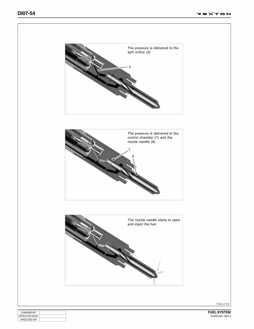
DI07-54
CHANGED BY
EFFECTIVE DATE
AFFECTED VIN
FUEL SYSTEMDI ENG SM - 2004.4
Y220_07107
The pressure is delivered to thespill orifice (3)
The pressure is delivered to thecontrol chamber (7) and thenozzle needle (8)
The nozzle needle starts to openand inject the fuel

DI07-55
CHANGED BY
EFFECTIVE DATE
AFFECTED VIN
FUEL SYSTEMDI ENG SM - 2004.4
Y220_07108
The nozzle needle blocks thecontrol chamber (9)
The valve opens due to thepressure decreases (10)
The pressure is delivered tocontrol chamber (11)

DI07-56
CHANGED BY
EFFECTIVE DATE
AFFECTED VIN
FUEL SYSTEMDI ENG SM - 2004.4
Y220_07109
It pushes the nozzle needle andthe control chamber opens (12)
The nozzle closes (13)

DI07-57
CHANGED BY
EFFECTIVE DATE
AFFECTED VIN
FUEL SYSTEMDI ENG SM - 2004.4
Y220_07110
• Small injection separation: min. 200
(duration between the end of pilot injection and start ofmain injection)
• Opening Delay
: Delayed time from applying operating voltage to start ofinjection
• Adjustment of feedback injection volume: C2I
Fuel pressure
Fuel pressure
• Minimum operating pressure: start injection over 100 bar
• Maximum operating pressure: 1,600 bar (max. operating pressure in normal conditions)
• Max overpressure: 2,100 bar
Maximum fuel volume at each injector cycle
• Pilot Injection 5 mm3
• Main Injection 85 mm3 (within 200 ~ 1,600 bar)
Y220_07111
Pilot injection
Main injection
Small injection separation
Opening delay definition
Injection rate
Injector drive pulse
Time ( )
10%signal
amplitude
10%signal
amplitude

DI07-58
CHANGED BY
EFFECTIVE DATE
AFFECTED VIN
FUEL SYSTEMDI ENG SM - 2004.4
Y220_07112
Injector control
The control current of the coil takes the following form:
The low current allows the Joule effect losses in the ECU and injector to be reduced. The call current is higher than thehold current because during the hold phase.
• The air gap between the valve and the coil is reduced and the electromagnetic force to be applied to the valve canthus be reduced. It is no longer necessary to overcome the valve inertia.
Note
Joule Effect: The principle that the heat produced by an electric current is equal to the product of the resistanceof the conductor, the square of the current, and the time for which it flows.
I: current (A)
R: resistance (ΩΩΩΩΩ)
T: time (sec)
H: calori (cal)
Heat capacity (H) = 0.24 I 2RT
Time
Hold periodPull-in period
Through pull
current = 7.5 A
Current
Peak pull current
= 22.0 A
Through hold current
= 7.5 A
Peak hold current
= 22.0 A

DI07-59
CHANGED BY
EFFECTIVE DATE
AFFECTED VIN
FUEL SYSTEMDI ENG SM - 2004.4
Y220_07113
Y220_07114
<Characteristic curve of discharge without pilot injection> <Characteristic curve of discharge with pilot injection>
Fuel InjectionOther than conventional diesel engine, common diesel engine use two steps injection as follows:
• Pilot Injection
• Main Injection
In above two step injection, the fuel injection volume and injection timing is calibrated according to fuel pressure and fueltemperature.
Pilot injection
Before starting main injection, a small amount of fuel is injected to help proper combustion. This injection is for reducingthe engine noise and vibration.
In other words, it makes the pressure increase in combustion chamber during combustion smooth to reduce the enginenoise and vibration (suppressing the surging). Basic values for pilot injection are adjusted according to the coolanttemperature and intake air pressure.
Main injectionActual output from engine is achieved by main injection.
The main injection determines the pilot injection has been occurred, then calculates the injection volume. Acceleratorpedal sensor, engine rpm, coolant temperature, intake air temperature and atmospheric pressure are basic date tocalculate the fuel injection volume in main injection.
1. Pilot injection
2. Main injection
1a. Ignition pressure with pilot injection
2a. Ignition pressure without pilot injection
<Characteristic curve of combustion chamber pressure during pilot injection>
Ne
ed
le l
ift (
k)
Angle of crankshaft
Cyl
ind
er
pre
ssu
re (
p)
Ne
ed
le l
ift (
k)
Cyl
ind
er
pre
ssu
re (
p)
Angle of crankshaft
Angle of crankshaft
Pre
ssu
re

DI07-60
CHANGED BY
EFFECTIVE DATE
AFFECTED VIN
FUEL SYSTEMDI ENG SM - 2004.4
Y220_07115
Y220_07116
Y220_07117
Y220_07118
Removal and Installation
Preceding Work: Removal of engine cover
1. Disconnect the injector return hose.
3. Unscrew the bolts and remove the fuel pipes.
Installation Notice
4. Unscrew the injector holder bolts.
Installation Notice
6. Remove the injectors with a special tool.
Notice• Plug the openings of the injectors with sealing caps.• Pull the dropped washer out from the engine with
a special tool.• Clean carbon deposite in hole with specific tool.
7. Install in the reverse order of removal.8. Do not forget to update C2I with Scan 100 and cross old
C2I on label fitted on engine.
NoticeReplace the copper washer, holder bolts and washerand fuel supply pipes with new ones.
2. Remove the relevant connector for the injector.
5. Disconnect the injector holder.
Notice
Plug the openings with sealing caps.
Installation Notice
• Replace the fuel pipes with new ones.
• Plug the openings of the common rail with sealingcaps.
Replace the bolts and washer with new ones.
Tightening torque 40 ± 10 Nm
Tightening torque9 ± 1.0 Nm
180° ± 10°

DI07-61
CHANGED BY
EFFECTIVE DATE
AFFECTED VIN
FUEL SYSTEMDI ENG SM - 2004.4
ECU Wiring Diagram

MEMO
.............................................................................................................................................................................................................................................................................................................................................................................................................................................................................
.............................................................................................................................................................................................................................................................................................................................................................................................................................................................................
.............................................................................................................................................................................................................................................................................................................................................................................................................................................................................
.............................................................................................................................................................................................................................................................................................................................................................................................................................................................................
.............................................................................................................................................................................................................................................................................................................................................................................................................................................................................
.............................................................................................................................................................................................................................................................................................................................................................................................................................................................................
.............................................................................................................................................................................................................................................................................................................................................................................................................................................................................
.............................................................................................................................................................................................................................................................................................................................................................................................................................................................................
.............................................................................................................................................................................................................................................................................................................................................................................................................................................................................
.............................................................................................................................................................................................................................................................................................................................................................................................................................................................................
.............................................................................................................................................................................................................................................................................................................................................................................................................................................................................
.............................................................................................................................................................................................................................................................................................................................................................................................................................................................................
.............................................................................................................................................................................................................................................................................................................................................................................................................................................................................
.............................................................................................................................................................................................................................................................................................................................................................................................................................................................................
.............................................................................................................................................................................................................................................................................................................................................................................................................................................................................
.............................................................................................................................................................................................................................................................................................................................................................................................................................................................................
.............................................................................................................................................................................................................................................................................................................................................................................................................................................................................
.............................................................................................................................................................................................................................................................................................................................................................................................................................................................................
.............................................................................................................................................................................................................................................................................................................................................................................................................................................................................
.............................................................................................................................................................................................................................................................................................................................................................................................................................................................................
.............................................................................................................................................................................................................................................................................................................................................................................................................................................................................
.............................................................................................................................................................................................................................................................................................................................................................................................................................................................................
.............................................................................................................................................................................................................................................................................................................................................................................................................................................................................
.............................................................................................................................................................................................................................................................................................................................................................................................................................................................................
.............................................................................................................................................................................................................................................................................................................................................................................................................................................................................
.............................................................................................................................................................................................................................................................................................................................................................................................................................................................................
.............................................................................................................................................................................................................................................................................................................................................................................................................................................................................
.............................................................................................................................................................................................................................................................................................................................................................................................................................................................................
.............................................................................................................................................................................................................................................................................................................................................................................................................................................................................

ENGINE CONTROL SYSTEM
SECTION DI08

DI08-1
CHANGED BY
EFFECTIVE DATE
AFFECTED VIN
ENGINE CONTROL SYSTEMDI ENG SM - 2004.4
ENGINE CONTROL SYSTEM
00SECTION DI08
Table of Contents
SENSORS FOR DIAGNOSIS ...................................... DI08-3
Engine ECU and other components ....................... DI08-3
Top view .................................................................. DI08-4
Side view ................................................................. DI08-5
ENGINE CONTROL SYSTEM ..................................... DI08-6
ECU ......................................................................... DI08-6
Fuel pressure control ........................................... DI08-12
Fuel injecstion control ........................................... DI08-13
Fuel flow control .................................................... DI08-14
Individual injector calibration (C2I) ....................... DI08-19
Minimum drive pulse (MDP) learning.................... DI08-21


DI08-3
CHANGED BY
EFFECTIVE DATE
AFFECTED VIN
ENGINE CONTROL SYSTEMDI ENG SM - 2004.4
Y220_08001
SENSORS FOR DIAGNOSIS
ECU/barometricsensor
Camshaft positionsensor
Fuel filter(water sensor)
Accelerator pedalsensor
HFM sensor / intake airtemperature sensor Preheating relay PTC Box
ENGINE ECU AND OTHER COMPONENTS

DI08-4
CHANGED BY
EFFECTIVE DATE
AFFECTED VIN
ENGINE CONTROL SYSTEMDI ENG SM - 2004.4
TOP VIEW
Y220_08002
Fuel pressure sensorBooster pressure
sensor
Injectors (5) Glow Plugs (5)

DI08-5
CHANGED BY
EFFECTIVE DATE
AFFECTED VIN
ENGINE CONTROL SYSTEMDI ENG SM - 2004.4
SIDE VIEW
Y220_08003
Coolant temperaturesensor
Knock sensors (2)
Fuel temperature sensorFuel pressure
regulating valveCrankshaft position
sensor

DI08-6
CHANGED BY
EFFECTIVE DATE
AFFECTED VIN
ENGINE CONTROL SYSTEMDI ENG SM - 2004.4
ENGINE CONTROL SYSTEM
Y220_08004
ECUAccording to input signals from various sensors, engine ECU calculates driver’s demand (position of the acceleratorpedal) and then controls overall operating performance of engine and vehicle on that time.
ECU receives signals from sensors through data line and then performs effective engine air-fuel ratio controls based onthose signals.
Engine speed is measured by crankshaft speed (position) sensor and camshaft speed (position) sensor determinesinjection order and ECU detects driver’s pedal position (driver’s demand) through electrical signal that generated byvariable resistance changes in accelerator pedal sensor.
Air flow (hot film) sensor detects intake air volume and then transmits to ECU. Especially, the engine ECU controls theair-fuel ratio by recognizing instant air volume changes through air flow sensor to pursue low emission gases (EGR valvecontrol). Furthermore, the ECU uses signals from coolant temperature and air temperature sensor, booster pressuresensor and atmospheric pressure sensor as compensation signal to respond to injection start and pilot injection setvalues and to various operations and variables.

DI08-7
CHANGED BY
EFFECTIVE DATE
AFFECTED VIN
ENGINE CONTROL SYSTEMDI ENG SM - 2004.4
Pin No.
1
2
3
4
5
6
7
8
9
10
11
12
13
14
15
16
17
18
19
20
21
22
23
24
25
26
27
28
29
30
31
32
33
34
35
36
37
38
39
Pin No.
40
41
42
43
44
45
46
47
48
49
50
51
52
53
54
55
56
57
58
59
60
61
62
63
64
65
66
67
68
69
70
71
72
73
74
75
76
77
78
Description
Engine ground
Engine ground
Main power (IG 1)
Main power (IG 1)
Main power (IG 1)
Rail pressure sensor power supply
ECU power hold relay
ABD signal
ACC 2 sensor ground
Auto cruise OFF
Auto cruise safety switch
A/C pressure signal
Fuel filter water detection warning lamp
Remote starter output
Glow plug control
Glow plug warning lamp
Rail pressure sensor signal
Rail pressure sensor ground
Engine ground
Auto cruise acceleration signal
ACC 2 sensor signal
K-LINE #1
K-LINE #2
Vehicle speed sensor signal input
IG 1
Clutch pedal switch
Description
Fuel filter water detection sensor
RPM signal output
Knock sensor signal (#2)
Knock sensor signal (#1)
Knock sensor ground (#1)
Auto cruise result signal
ACC 1 sensor ground
CAN- H1
ACC 2 sensor power supply
Brake lamp switch
Vehicle speed indication lamp
Preheater #1
Preheater #2
Knock sensor ground (#2)
HFM sensor (air temperature sensor)
Engine ground
Auto cruise deceleration signal
ACC 1 sensor signal
ACC 1 sensor power supply
CAN -LO
A/C cycling pressure switch
Brake pedal switch
Trip computer

DI08-8
CHANGED BY
EFFECTIVE DATE
AFFECTED VIN
ENGINE CONTROL SYSTEMDI ENG SM - 2004.4
Pin No.
79
80
81
82
83
84
85
86
87
88
89
90
91
92
93
94
95
96
97
98
99
100
Pin No.
101
102
103
104
105
106
107
108
109
110
111
112
113
114
115
116
117
118
119
120
121
Description
A/C relay
Cooling fan LOW
Cooling fan HIGH
Crankshaft position sensor (-)
HFM sensor (air mass sensor)
HFM sensor (ground)
HFM sensor (power supply)
IMV (fuel pressure regulating valve)
Engine ground
Crankshaft position sensor (+)
Waste gate actuator
EGR valve
Booster pressure sensor signal
Booster pressure sensor ground
Description
Coolant temperature signal
Coolant temperature sensor ground
Camshaft position sensor signal
Camshaft position sensor ground
Engine check warning lamp
Blower switch
Booster pressure sensor power supply
Fuel temperature sensor signal
Fuel temperature sensor ground
Camshaft position sensor power supply
Immobilizer
Engine check warning lamp
Injector #1
Injector #4
Injector #3
Injector ground (#1, 3, 4)
Injector ground (#2, 5)
Injector #5
Injector #2

DI08-9
CHANGED BY
EFFECTIVE DATE
AFFECTED VIN
ENGINE CONTROL SYSTEMDI ENG SM - 2004.4
ECU Inputs·Outputs
Control
E
C
U
Structure and Function of ECU
Function of ECU
ECU receives and analyzes signals from various sensors and then modifies those signals into permissible voltage levelsand analyzes to control respective actuators.
ECU microprocessor calculates injection period and injection timing proper for engine piston speed and crankshaftangle based on input data and stored specific map to control the engine power and emission gas.
Output signal of the ECU microprocessor drives pressure control valve to control the rail pressure and activatesinjector solenoid valve to control the fuel injection period and injection timing; so controls various actuators inresponse to engine changes. Auxiliary function of ECU has adopted to reduce emission gas, improve fuel economyand enhance safety, comforts and conveniences. For example, there are EGR, booster pressure control, autocruise(export only) and immobilizer and adopted CAN communication to exchange data among electrical systems(automatic T/M and brake system) in the vehicle fluently. And Scanner can be used to diagnose vehicle status anddefectives.
Operating temperature range of ECU is normally -40 ~ +85°C and protected from factors like oil, water and electromag-netism and there should be no mechanical shocks.
To control the fuel volume precisely under repeated injections, high current should be applied instantly so there isinjector drive circuit in the ECU to generate necessary current during injector drive stages.
Current control circuit divides current applying time (injection time) into full-in-current-phase and hold-current-phase andthen the injectors should work very correctly under every working condition.
Output
Injector
EGR system
Fuel pressure regulating valve (IMV)
Electrical fan control (Low/High-speed)
A/C compressor relay
Glow plug relay
Immobilizer
Warning lights
(Water warning light, glow plug indica-
tor light, engine warning light)
Preheater (auxiliary heater)
K - line
CAN communication
Self-diagnosis
Inputs
Booster pressure sensor
Atmospheric pressure sensor(Built-in ECU)
Air flow sensor (HFM)
Coolant temperature sensor
Fuel temperature sensor
Fuel pressure sensor
Fuel filter water sensor
Knock sensor
crankshaft position sensor
camshaft position sensor
Accelerator sensor
Vehicle speed sensor
Switch input signal
(IG, brake, clutch, A/C signal, A/C
compressor)
DI08-10
CHANGED BY
EFFECTIVE DATE
AFFECTED VIN
ENGINE CONTROL SYSTEMDI ENG SM - 2004.4
Control Function of ECU• Controls by operating stages
: To make optimum combustion under every operating stage, ECU should calculate proper injection volume ineach stage by considering various factors.
• Starting injection volume control
: During initial starting, injecting fuel volume will be calculated by function of temperature and engine crankingspeed.
Starting injection continues from when the ignition switch is turned to ignition position to till the engine reachesto allowable minimum speed.
• Driving mode control
: If the vehicle runs normally, fuel injection volume will be calculated by accelerator pedal travel and engine rpmand the drive map will be used to match the drivers inputs with optimum engine power.

DI08-11
CHANGED BY
EFFECTIVE DATE
AFFECTED VIN
ENGINE CONTROL SYSTEMDI ENG SM - 2004.4
ECU - Removal and Installation
1. Flip up the front passenger’s seat and remove the ECUcover nuts.
2. Remove the ECU bracket nuts.
Y220_08005
Y220_08006
Y220_08007
3. Unscrew the ECU connect bolt and remove the ECUassembly.
4. Install in the reverse order of removal.
5. Backup the below data with Scan-i when replacing theECU.
- Current ECU data
- Vehicle Identification Number (VIN)
- Variant coding data
- Then, input the data into new ECU. For immobilizerequipped vehicle, additional coding operation isnecessary.

DI08-12
CHANGED BY
EFFECTIVE DATE
AFFECTED VIN
ENGINE CONTROL SYSTEMDI ENG SM - 2004.4
FUEL PRESSURE CONTROL
Fuel Pressure Control ElementsPressure control consists of 2 principle modules.
• Determines rail pressure according to engine operating conditions.
• Controls IMV to make the rail pressure to reach to the required value.
Pressure in the fuel rail is determined according to engine speed and load on the engine. The aim is to adapt theinjection pressure to the engine’s requirements.
• When engine speed and load are high
: The degree of turbulence is very great and the fuel can be injected at very high pressure in order to optimizecombustion.
• When engine speed and load are low
: The degree of turbulence is low. If injection pressure is too high, the nozzle’s penetration will be excessive and partof the fuel will be sprayed directly onto the sides of the cylinder, causing incomplete combustion. So there occurssmoke and damages engine durability.
Fuel pressure is corrected according to air temperature, coolant temperature and atmospheric pressure and to takeaccount of the added ignition time caused by cold running or by high altitude driving. A special pressure demand isnecessary in order to obtain the additional flow required during starts. This demand is determined according to injectedfuel and coolant temperature.
Fuel Pressure ControlRail pressure is controlled by closed loop regulation of IMV. A mapping system – open loop – determines the currentwhich needs to be sent to the actuator in order to obtain the flow demanded by the ECU. The closed loop will correct thecurrent value depending on the difference between the pressure demand and the pressure measured.
• If the pressure is lower than the demand, current is reduced so that the fuel sent to the high pressure pump isincreased.
• If the pressure is higher than the demand, current is increased so that the fuel sent to the high pressure pump isreduced.
Y220_08008
Flow demand
Engine speed
Measured railpressure
OpenIMV current
IMV
Current
PIGgovernor
Error Correction
Rail pressuredemand

DI08-13
CHANGED BY
EFFECTIVE DATE
AFFECTED VIN
ENGINE CONTROL SYSTEMDI ENG SM - 2004.4
FUEL INJECSTION CONTROL
Fuel Injection ControlInjection control is used in order to determine the characteristics of the pulse which is sent to the injectors.
Injection control consists as below.
• Injection timing
• Injection volume
• Translating fuel injection timing and injection volume into values which can be interpreted by the injector driver.
- a reference tooth (CTP)
- the delay between this tooth and the start of the pulse (Toff)
- the pulse time (Ton)
Main injection timing control
The pulse necessary for the main injection is determined as a function of the engine speed and of the injected flow.
The elements are;
• A first correction is made according to the air and coolant temperatures.
This correction makes it possible to adapt the timing to the operating temperature of the engine. When the engine iswarm, the timing can be retarded to reduce the combustion temperature and polluting emissions (NOx). When theengine is cold, the timing advance must be sufficient to allow the combustion to begin correctly.
• A second correction is made according to the atmospheric pressure.
This correction is used to adapt the timing advance as a function of the atmospheric pressure and therefore the altitude.
• A third correction is made according to the coolant temperature and the time which has passed since starting.
This correction allows the injection timing advance to be increased while the engine is warming up (initial 30 seconds).The purpose of this correction is to reduce the misfiring and instabilities which are liable to occur after a cold start.
• A fourth correction is made according to the pressure error.
This correction is used to reduce the injection timing advance when the pressure in the rail is higher than thepressure demand.
• A fifth correction is made according to the rate of EGR.
This correction is used to correct the injection timing advance as a function of the rate of exhaust gas recirculation.When the EGR rate increases, the injection timing advance must in fact be increased in order to compensate for thefall in termperature in the cylinder.
During starting, the injection timing must be retarded in order to position the start of combustion close to the TDC. To dothis, special mapping is used to determine the injection timing advance as a function of the engine speed and of thewater temperature. This requirement only concerns the starting phase, since once the engine has started the systemmust re-use the mapping and the corrections described previously.
Pilot injection timing control
The pilot injection timing is determined as a function of the engine speed and of the total flow.
The elements are;
• A first correction is made according to the air and coolant temperatures.
This correction allows the pilot injection timing to be adapted to the operating temperature of the engine.
• A second correction is made according to the atmospheric pressure.
This correction is used to adapt the pilot injection timing as a function of the atmospheric pressure and therefore thealtitude.
During the starting phase, the pilot injection timing is determined as a function of the engine speed and of the coolanttemperature.

DI08-14
CHANGED BY
EFFECTIVE DATE
AFFECTED VIN
ENGINE CONTROL SYSTEMDI ENG SM - 2004.4
FUEL FLOW CONTROL
Main Flow Control
The main flow represents the amount of fuel injected into the cylinder during the main injection. The pilot flow representsthe amount of fuel injected during the pilot injection.
The total fuel injected during 1 cycle (main flow + pilot flow) is determined in the following manner.
: The driver’s demand is compared with the value of the minimum flow determined by the idle speed controller.
• When the driver depress the pedal, it is his demand which is taken into account by the system in order todetermine the fuel injected.
• When the driver release the pedal, the idle speed controller takes over to determine the minimum fuel whichmust be injected into the cylinder to prevent the enigne from stalling.
It is therefore the greater of these 2 values which is retained by the system. This value is then compared with the lowerflow limit determined by the ASR trajectory control system. As soon as the injected fuel becomes lower than the flowlimit determined by the ASR trajectory control system, the antagonistic torque (engine brake) transmitted to the drivewheels exceeds the adherence capacity of the vehicle and there is therefore a risk of the drive wheels locking. Thesystem thus chooses the greater of these 2 values (main flow & pilot flow) in order to prevent any loss of control of thevehicle during a sharp deceleration.
This value is then compared with the flow limit determined by the cruise control. As soon as the injected fuel becomeslower than the flow limit determined by the cruise control, the vehicle’s speed falls below the value required by the driver.The system therefore chooses the greater of these 2 values in order to maintain the speed at the required level.
This valve is then compared with the flow limit determined by the flow limitation strategy. This strategy allows the flow tobe limited as a function of the operating conditions of the engine. The system therefore chooses the smaller of these 2values in order to protect the engine. This value is then compared with the fuel limit determined by the ASR trajectorycontrol system.
As soon as the injected fuel becomes higher than the fuel limit determined by the ASR trajectory control system, theengine torque transmitted to the wheels exceeds the adhesion capacity of the vehicle and there is a risk of the drivewheels skidding. The system therefore chooses the smaller of the two values in order to avoid any loss of control of thevehicle during accelerations.
The anti-oscillation strategy makes it possible to compensate for fluctuations in engine speed during transient conditions.This strategy leads to a fuel correction which is added to the total fuel of each cylinder. The correction is determinedbefore each injection as a function of the instantaneous engine speed.
A switch makes it possible to change over from the supercharge fuel to the total fuel according to the state of the engine.
• Until the stating phase has finished, the system uses the supercharged fuel.
• Once the engine changes to normal operation, the system uses the total fuel.
The main fuel is obtained by subtracting the pilot injection fuel from the total fuel.
A mapping determines the minimum fuel which can control an injector as a function of the rail pressure. As soon as themain fuel falls below this value, the fuel demand changes to 0 because in any case the injector is not capable of injectingthe quantity demand.

DI08-15
CHANGED BY
EFFECTIVE DATE
AFFECTED VIN
ENGINE CONTROL SYSTEMDI ENG SM - 2004.4
The driver demand is the translation of the pedal position into the fuel demand. It is calculated as a function of the pedalposition and of the engine speed. The driver demand is filtered in order to limit the hesitations caused by rapid changesof the pedal position. A mapping determines the maximum fuel which can be injected as a function of the driver demandand the rail pressure. Since the flow is proportional to the injection time and to the square root of the injection pressure,it is necessary to limit the flow according to the pressure in order to avoid extending the injection for too long into theengine cycle. The system compares the driver demand with this limit and chooses the smaller of the 2 values. The driverdemand is then corrected according to the coolant temperature. This correction is added to the driver demand.
Y220_08009
Driver Demand
Engine status
Main flow < controllable min.flow
Main flow request
Driver’s request
Idle speed controller
ASR traction control
Cruise control
Flow limit
Speed limiter
ASR traction control
Anti-oscillation strategy
Overflow
Programmed engine stop
Pilot injection flow
0

DI08-16
CHANGED BY
EFFECTIVE DATE
AFFECTED VIN
ENGINE CONTROL SYSTEMDI ENG SM - 2004.4
The idle speed controller consists of 2 principal modules:
• The first module determines the required idle speed according to:
- The operating conditions of the engine (coolant temperature, gear engaged)
- Any activation of the electrical consumers (power steering, air conditioning, others)
- The battery voltage
- The presence of any faults liable to interface with the rail pressure control or the injection control. In this case,the accelerated idle speed is activated to prevent the engine from stalling when operating in degraded mode.
- It is possible to increase or to reduce the required idle speed with the aid of the diagnostic tool.
• The second module is responsible for providing closed loop control of the engine’s idle speed by adapting theminimum fuel according to the difference between the required idle speed and the engine speed.
Idle Speed Controller
Flow Limitation
Pilot flow control
The flow limitation strategy is based on the following strategies:
• The flow limitation depending on the filling of the engine with air is determined according to the engine speed and theair flow. This limitation allows smoke emissions to be reduced during stabilized running.
• The flow limitation depending on the atmospheric pressure is determined according to the engine speed and theatmospheric pressure. It allows smoke emissions to be reduced when driving at altitude.
• The full load flow curve is determined according to the gear engaged and the engine speed. It allows the maximumtorque delivered by the engine to be limited.
• A performance limitation is introduced if faults liable to upset the rail pressure control or the injection control aredetected by the system. In this case, and depending on the gravity of the fault, the system activates:
- Reduced fuel logic 1: Guarantees 75 % of the performance without limiting the engine speed.
- Reduced fuel logic 2: Guarantees 50 % of the performance with the engine speed limited to 3,000 rpm.
- Reduce fuel logic 3: Limits the engine speed to 2,000 rpm.
The system chooses the lowest of all these values.
A correction depending on the coolant temperature is added to the flow limitation. This correction makes it possible toreduce the mechanical stresses while the engine is warming up. The correction is determined according to the coolanttemperature, the engine speed and the time which has passed since starting.
Superchager Flow Demand
The supercharge flow is calculated according to the engine speed and the coolant temperature. A correction dependingon the air temperature and the atmospheric pressure is made in order to increase the supercharge flow during coldstarts. It is possible to alter the supercharge flow value by adding a flow offset with the aid of the diagnostic tool.
The pilot flow represents the amount of fuel injected into the cylinder during the pilot injection. This amount is determinedaccording to the engine speed and the total flow.
• A first correction is made according to the air and water temperature.
This correction allows the pilot flow to be adapted to the operating temperature of the engine. When the engine iswarm, the ignition time decreases because the end-of-compression temperature is higher. The pilot flow can thereforebe reduced because there is obviously less combustion noise when the engine is warm.
• A second correction is made according to the atmospheric pressure.
This correction is used to adapt the pilot flow according to the atmospheric pressure and therefore the altitude.
During starting, the pilot flow is determined on the basis of the engine speed and the coolant temperature.

DI08-17
CHANGED BY
EFFECTIVE DATE
AFFECTED VIN
ENGINE CONTROL SYSTEMDI ENG SM - 2004.4
Y220_08011
Balancing of the point to point flows
The pulse of each injector is corrected according to the difference in instantaneous speed measured between 2 succes-sive injectors.
• The instantaneous speeds on two successive injections are first calculated.
• The difference between these two instantaneous speeds is then calculated.
• Finally, the time to be added to the main injection pulse for the different injectors is determined. For each injector,this time is calculated according to the initial offset of the injector and the instantaneous speed difference.
Detection of an injector which has stuck closedThe cylinder balancing strategy also allows the detection of an injector which has stuck closed. The difference in instantaneousspeed between 2 successive injections then exceeds a predefined threshold. In this case, a fault is signaled by the system.
Cylinder Balancing Strategy
Accelerometer StrategyResetting the pilot injection
The accelerometer is used to reset the pilot injection flow in closed loop for each injector. This method allows thecorrection of any injector deviations over a period of time. The principle of use of the accelerometer is based on thedetection of the combustion noises.
The sensor is positioned in such a way as to receive the maximum signal for all the cylinders. The raw signals from theaccelerometer are processed to obtain a variable which quantifies the intensity of the combustion. This variable, knownas the ratio, consists of the ratio between the intensity of the background noise and the combustion noise.
• A first window is used to establish the background noise level of the accelerometer signal for each cylinder. Thiswindow must therefore be positioned at a moment when there cannot be any combustion.
• The second window is used to measure the intensity of the pilot combustion. Its position is such that only thecombustion noises produced by the pilot injection are measured . It is therefore placed just before the main injection.
The accelerometer does not allow any evaluation of the quantity injected. However, the pulse value will be measuredwhen the injector starts injection and this pulse value is called the MDP (Minimum Drive Pulse). On the basis of thisinformation, it is possible to efficiently correct the pilot flows. The pilot injection resetting principle therefore consists ofdetermining the MDP, in other words the pulse corresponding to the start of the increase in value of the ratio (increaseof vibration due to fuel combustion).
Cylinder pressure
Needle lift
Ratio
Minor pilot injection
No pilot injection
No injection
Major pilot injection

DI08-18
CHANGED BY
EFFECTIVE DATE
AFFECTED VIN
ENGINE CONTROL SYSTEMDI ENG SM - 2004.4
This is done periodically under certain operating conditions. When the resetting is finished, the new minimum pulsevalue replaces the value obtained during the previous resetting. The first MDP value is provided by the C2I. Eachresetting then allows the closed loop of the MDP to be updated according to the deviation of the injector.
Detection of leaks in the cylinders
The accelerometer is also used to detect any injector which may have stuck open. The detection principle is based onmonitoring the ratio. If there is a leak in the cylinder, the accumulated fuel self-ignites as soon as the temperature andpressure conditions are favorable (high engine speed, high load and small leak).
This combustion is set off at about 20 degrees before TDC and before main injection.
The ratio therefore increases considerably in the detection window. It is this increase which allows the leaks to bedetected. The threshold beyond which a fault is signaled is a percentage of the maximum possible value of the ratio.Because of the severity of the recovery process (engine shut-down), the etection must be extremely robust.
An increase in the ratio can be the consequence of various causes:
• Pilot injection too strong
• Main combustion offset
• Fuel leak in the cylinder
If the ratio becomes too high, the strategy initially restricts the pilot injection flow and retards the main injection. If theratio remains high despite these interventions, this shows that a real leak is present, a fault is signaled and the engineis shut down.
Detection of an accelerometer fault
This strategy permits the detection of a fault in the sensor or in the wiring loom connecting the sensor to the ECU. It isbased on detection of the combustion. When the engine is idling, the detection window is set too low for the combustioncaused by the main injection. If the ratio increases, this shows that the accelerometer is working properly, but otherwisea fault is signaled to indicate a sensor failure. The recovery modes associated with this fault consist of inhibition of thepilot injection and discharge through the injectors.

DI08-19
CHANGED BY
EFFECTIVE DATE
AFFECTED VIN
ENGINE CONTROL SYSTEMDI ENG SM - 2004.4
INDIVIDUAL INJECTOR CALIBRATION (C2I)Injected fuel is proportional to square root of injection time and rail pressure.
It is function between pulse and rail pressure and fuel injection curve is called injector characteristics curve having thefollowing shape.
Common rail injectors are very accurate components. They are able to inject fuel delivery between 0.5 to 100 mg/strunder pressure varying from 150 to 1600 bar.
This high level of accuracy requires very low machining tolerances (few ).
Nevertheless, due to the machining dispersion, the loss of charge through the functional orifices, the friction betweenmoving parts and electromagnetic field level are different from one injector to the other. So, the difference of fuel deliveryfor the same pressure and the same pulse can reach 5 mg/str from one injector to the other. It is impossible to controlefficiently the engine with such a dispersion between the different injectors. It is necessary to add a correction thatallows injecting the demanded fuel delivery whatever the initial hydraulic characteristics of the injector is. The methodconsists in correcting the pulse that is applied to the injector with an offset that depends on the initial hydraulic map ofthe injector. So, the pulse should be corrected according to characteristics of each injector.
Y220_08012
De
live
ry (
mm
3/s
t)
Drive pulse (µsec)

DI08-20
CHANGED BY
EFFECTIVE DATE
AFFECTED VIN
ENGINE CONTROL SYSTEMDI ENG SM - 2004.4
C2I is composed of models on these characteristics of injectors.
C2I consists of 16-digit; composed of numbers from 1 to 9 and alphabets from A to F. ECU remembers C2I, character-istics of each injector, to make the most optimal fuel injection.
• When replacing the injector, C2I code on the top of new injector should be input into ECU because the ECU isremembering the injector’s C2I value. If C2I is not input, engine power drops and occurs irregular combustion.
• When ECU is replaced, C2I code of every injector should be input. If not, cannot accelerate the vehicle even whenthe accelerator pedal is depressed.
Y220_08013
For coding of C2I, refer to “Diagnosis” section
C2I Number(16 digits)
C2Ivalue

DI08-21
CHANGED BY
EFFECTIVE DATE
AFFECTED VIN
ENGINE CONTROL SYSTEMDI ENG SM - 2004.4
MINIMUM DRIVE PULSE (MDP) LEARNINGWhen the pulse value that the injector starts injection is measured, it is called mininum drive pulse (MDP). Through MDPcontrols, can correct pilot injections effectively. Pilot injection volume is very small, 1 ~ 2 mm/str, so precise control ofthe injector can be difficult if it gets old. So there needs MDP learning to control the very small volume precisely throughlearning according to getting older injectors.
Learning Conditions
Coolant temperature
Vehicle speed
Intake manifold pressure
Engine speed
Battery voltage
Fuel temperature
Initial MDP learning on each injector
> 75°C
> 50 Km/h (over 5 seconds)
> 0.7 bar
> 2,500 rpm
10 V < MDP < 16 V
0 < fuel temperature < 80 °C
5 seconds
Trouble Codes
Trouble code
P1171
P1172
P1173
P1174
P1175
Description
Fault MDP learning on injector No. 1
Fault MDP learning on injector No. 2
Fault MDP learning on injector No. 3
Fault MDP learning on injector No. 4
Fault MDP learning on injector No. 5
Diagnosis
• Check each injector

DI08-22
CHANGED BY
EFFECTIVE DATE
AFFECTED VIN
ENGINE CONTROL SYSTEMDI ENG SM - 2004.4
Accelerator Pedal Sensor
<Location of accelerator pedal sensor> <When depressing the accelerator pedaland brake pedal simultaneously>
Accelerator pedal sensor changes accelerator pedal position into electrical signal and then sends to ECU to let knowthe driver’s demand. There are 2 sensors in the accelerator pedal sensor. Accelerator pedal No.1 (ACC 1) sensor signaldetermines fuel injection volume and injection timing during driving, and accelerator pedal No. 2 (ACC 2) sensor signalcompares whether the No. 1 sensor signal value is correct.
If accelerator pedal No. 1 and 2 sensors are defective, ECU remembers defect code, and acceleration responses aregetting bad and engine rpm hardly increases.
Y220_08014
Y220_08015
Notice
When depressing the accelerator pedal and brake pedal simultaneously while driving, the acceleration responsewill be diminished abruptly and cannot drive with over 70 km/h even though depressing the accelerator pedalto its end. At this time, the trouble code of “P-1124 Accelerator pedal sensor stuck” is stored into ECU. Ifdepressing the accelerator pedal over 3 times, it will be resumed to normal condition.
* For detailed information, refer to “Diagnosis” section in this manual.
Signal 1
Ground
Signal 2
Ground
<Circuit diagram of Accelerator pedal sensor>

DI08-23
CHANGED BY
EFFECTIVE DATE
AFFECTED VIN
ENGINE CONTROL SYSTEMDI ENG SM - 2004.4
<Coolant temperature sensor> <Output characteristics of coolant temperaturesensor>
Coolant Temperature Sensor
Coolant temperature sensor is a NTC resister that sends coolant temperature to ECU.
NTC resister has characteristics that if the engine temperature rises, the resistance lowers so the ECU detects loweringsignal voltages.
If the fuel injected into the engine through injector has more turbulence, then combusts very well. However, if enginetemperature is too low, the fuel injected as foggy state forms big compounds causing incomplete combustion. So thesensor detects coolant temperature and changes coolant temperature changes into voltage then sends to ECU toincrease the fuel volume during cold start for better starting. And detects engine overheating for fuel volume reduction toprotect the engine.
ECU functions as below with coolant temperature sensor signals.
• When engine is cold, controls fuel volume to correct idle speed.
• When engine is overheated, controls electrical fan and A/C compressor to protect the engine.
• Sends information for emission control.
<Circuit diagram of coolant temperature sensor>
Y220_08016
Y220_08017
Temperature (°C)
20
50
80
120
NTC 1 Resistance (ΩΩΩΩΩ)
2,550
826
321
123
NTC 1 Resistance (ΩΩΩΩΩ)
6,062
1,800
638
200
Temp.
Resistance
Signal
Ground
Auto amp

DI08-24
CHANGED BY
EFFECTIVE DATE
AFFECTED VIN
ENGINE CONTROL SYSTEMDI ENG SM - 2004.4
<Boost pressure sensor>
Boost Pressure Sensor
<Location of boost pressure sensor>
Boost pressure sensor uses piezo element and uses only 3 terminals out of 6.
It sets fuel injection timing and corrects fuel injection volume according to atmospheric pressure.
The other function is determining EGR operation stops.
• Output voltage calculationVO = VS x ( P x 0.004 - 0.04)VO : Output voltageVS : Supply voltageP : Applying voltage
<Output characteristics of sensor>
Y220_08018
Y220_08019
Performance proofing pressure range
Performance proofing temperature range
Storage proofing temperature range
Performance proofing supply voltage
Max. consuming current
Responsibility
Tightening torque
20 ~ 250 KPa
- 40 ~ 110°C
- 40 ~ 125°C
4.85 ~ 5.35 V
10 mA (supply voltage at 5.35 V)
TR 7ms
10 Nm
Not using terminals
Vo
ltag
e (
V)
Pressure (bar)
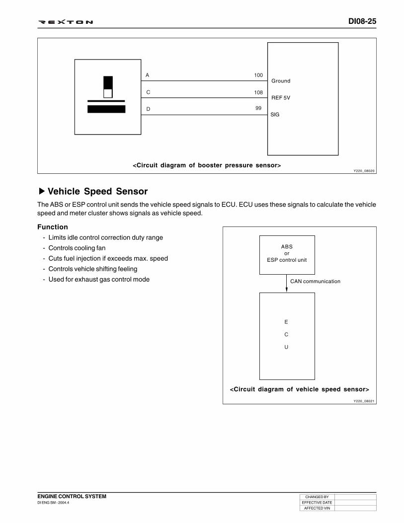
DI08-25
CHANGED BY
EFFECTIVE DATE
AFFECTED VIN
ENGINE CONTROL SYSTEMDI ENG SM - 2004.4
Vehicle Speed SensorThe ABS or ESP control unit sends the vehicle speed signals to ECU. ECU uses these signals to calculate the vehiclespeed and meter cluster shows signals as vehicle speed.
Function
- Limits idle control correction duty range
- Controls cooling fan
- Cuts fuel injection if exceeds max. speed
- Controls vehicle shifting feeling
- Used for exhaust gas control mode
ABSor
ESP control unit
CAN communication
<Circuit diagram of booster pressure sensor>Y220_08020
Ground
REF 5V
SIG
<Circuit diagram of vehicle speed sensor>
Y220_08021

DI08-26
CHANGED BY
EFFECTIVE DATE
AFFECTED VIN
ENGINE CONTROL SYSTEMDI ENG SM - 2004.4
Other switches
Brake switch
Brake switch detects brake pedal operations and then sends to engine ECU. It has dual structure with 2 combinedswitches and there are brake switch 1 and 2. When these 2 signals are input, engine ECU recognizes as normal brakesignals. These switch signals are related with accelerator pedal sensor operations and used to control the fuel volumeduring braking. It means there are no problems in operating accelerator pedal when the brake pedal is operated but thefuel volume reduces if operates brake pedal while the accelerator pedal is depressed.
<Brake switch circuit>
Clutch pedal switch
Clutch pedal switch is installed on the upper of the clutch and sends clutch pedal operations to engine ECU. Contacttype switch allows engine ECU to recognize the shifting points to correct the fuel volume. It means it corrects fluctuationhappens during gear shifting. Another different function is canceling auto cruise function if equipped (auto cruise control- equipped for export).
<Clutch pedal switch circuit>
Y220_08022
Y220_08023
Brake pedal switch (NC)
Brake lamp switch (NO)
Clutch pedal switch (NO)
Engineground
Barometric Pressure SensorIt is built-in the ECU and detects absolute pressure of atmosphere to correct fuel injection timing and injection volumeaccording to altitude.

ELECTRIC DEVICES ANDSENSORS
SECTION DI09

DI09-1
CHANGED BY
EFFECTIVE DATE
AFFECTED VIN
ELECTRIC DEVICES AND SENSORSDI ENG SM - 2004.4
ELECTRIC DEVICESAND SENSORS
00SECTION DI09
Table of Contents
ELECTRIC DEVICES AND SENSORS ........................ DI09-3
Sensors in engine compartment ............................. DI09-3
Electric devices in engine compartment ................. DI09-4
Specifications .......................................................... DI09-5
Circuit diagram of preheating system..................... DI09-6
Circuit diagram of starting and alternator .............. DI09-7
TROUBLE DIAGNOSIS ............................................... DI09-8
General ................................................................... DI09-8
Alternator .............................................................. DI09-10
Starter ................................................................... DI09-12
Preheating system ................................................ DI09-14
Preheating time relay ............................................ DI09-16
Glow plug .............................................................. DI09-17
SPECIAL TOOLS AND EQUIPMENT ........................ DI09-19


DI09-3
CHANGED BY
EFFECTIVE DATE
AFFECTED VIN
ELECTRIC DEVICES AND SENSORSDI ENG SM - 2004.4
ELECTRIC DEVICES AND SENSORS
Y220_09001
SENSORS IN ENGINE COMPARTMENT
Fuel pressure sensor
Camshaft positionsensor
Coolant temperaturesensor
Fuel temperaturesensor Knock sensor
Crankshaft positionsensor
Booster pressuresensor
Oil pressure switch

DI09-4
CHANGED BY
EFFECTIVE DATE
AFFECTED VIN
ELECTRIC DEVICES AND SENSORSDI ENG SM - 2004.4
ELECTRIC DEVICES IN ENGINE COMPARTMENT
Y220_09002
Alternator Glow plug
Air conditioner compressor Starter
CapacityPTC equipped vehicle
: 12V - 140A
FFH equipped vehicle: 12V - 115A

DI09-5
CHANGED BY
EFFECTIVE DATE
AFFECTED VIN
ELECTRIC DEVICES AND SENSORSDI ENG SM - 2004.4
Type
Output power
No load test @ 12 volts
Drive pinion speed at no load
Drive pinion speed at load
Brush length
Armature diameter
Armature run-out
Segment groove depth
Type
Output voltage / current
Regulator type
Regulating voltage
Brush
Type
Capacity
Rupture capatity
Type
Rated voltage
Circuit connection
Preheating time
SPECIFICATIONS
Starter
Alternator
Battery
Glow plug
WP220
2.2
160
4500
1700/430
18
55
0.1
21.7
CS128D
PTC equipped vehicle: 12V-140A
FFH equipped vehicle: 12V-115A
←
14.6
12.5
2
7
M F
12V - 90AH
160
Seized type
11.5
Parallel
Max. 60 ~ 90
Description Specification
Length
Quantity
Wear limit
-
Kw
A
rpm
rpm/A
mm
mm
mm
mm
-
V/A
-
V
mm
-
mm
-
AH
RC
-
-
-
sec
Unit

DI09-6
CHANGED BY
EFFECTIVE DATE
AFFECTED VIN
ELECTRIC DEVICES AND SENSORSDI ENG SM - 2004.4
CIRCUIT DIAGRAM OF PREHEATING SYSTEM
Y220_09003

DI09-7
CHANGED BY
EFFECTIVE DATE
AFFECTED VIN
ELECTRIC DEVICES AND SENSORSDI ENG SM - 2004.4
CIRCUIT DIAGRAM OF STARTING AND ALTERNATOR
Y220_09004

DI09-8
CHANGED BY
EFFECTIVE DATE
AFFECTED VIN
ELECTRIC DEVICES AND SENSORSDI ENG SM - 2004.4
TROUBLE DIAGNOSIS
GENERAL
Correction• Charging the battery or replace
the battery.
• Repair or replace the batterycable.
• Repair or replace the startermotor/starter motor circuit.
• Replace the ignition switch.
• Repair the ground short.
• Charging the battery or replacethe battery.
• Repair or replace the batterycable.
• Repair or replace the startermotor.
• Repair or replace the startermotor.
• Replace the ignition switch.
• Replace the starter motor.
• Replace the flywheel.
• Repair the open circuit.
• Adjust the belt tension or replacethe belt.
• Repair the open or a short circuit.
• Replace the battery.
• Repair the open ground circuit.
• Repair or replace the chargingindicator lamp/fuse.
• Replace the ignition switch.
• Repair the circuit.
• Repair or replace the batterycable.
• Adjust the belt tension or replacethe belt.
• Repair the wiring harness.
• Replace generator
• Repair wiring
ConditionNo crank
Probable Cause• Low battery voltage.
• Battery cable is loose,corroded, or damaged.
• Faulty starter motor or startermotor circuit is open.
• Faulty ignition switch.
• Ground short.
• Low battery voltage.
• Battery.
• Battery cables are loose,corroded, or damaged.
• Faulty starter motor.
• Faulty starter motor.
• Faulty ignition switch.
• Broken the clutch pinion gear orfaulty starter motor.
• Broken the flywheel ring gear.
• Connected circuit is open.
• Loosen the generator drive belt.
• The circuit is open or a short.
• Battery run down.
• Open ground circuit.
• Charging indicator lamp is blownor fuse is blown.
• Faulty ignition switch.
• Generator ground circuit is openor a short.
• Battery cable is corroded ordamaged.
• Loosen the generator drive belt.
• Faulty wiring harness.
• Generator voltage regulator faulty
• Voltage detecfing wiring faulty
Charging indicator lamp does notput out lights after starting theengine
Crank ok, but too slow
Starter motor does not stop
Starter motor running, but notcranking
Battery discharge
Charging indicator lamp does notwork when the ignition switch on(engine does not work)
Battery over charging

DI09-9
CHANGED BY
EFFECTIVE DATE
AFFECTED VIN
ELECTRIC DEVICES AND SENSORSDI ENG SM - 2004.4
Action• Replace ignition coil
• Replace distribator (or sensor)
• Replace spark plug or adjustclearance
• Resetting valve timing
• Replace spark plug or adjustclearance
• Replace ignition coil
• Resetting valve timing
• Resetting valve timing
SymptomHard engine starting
Cause• Ignition coil faulty
• Distributor (including opticalsensor) faulty
• Spark plug malfuntion
• Ignition timing faulty (spark pluglight is normal)
• Spark plug malfunction
• Ignition coil faulty
• Ignition timing faulty
• Ignition timing faulty
Unstable engine idling
Enging acceralation malfunction

DI09-10
CHANGED BY
EFFECTIVE DATE
AFFECTED VIN
ELECTRIC DEVICES AND SENSORSDI ENG SM - 2004.4
3. Alternator
4. Plug connection
ALTERNATOR
1. Cooling fan
2. Bolt ............................................................. 45 Nm
Y220_09005

DI09-11
CHANGED BY
EFFECTIVE DATE
AFFECTED VIN
ELECTRIC DEVICES AND SENSORSDI ENG SM - 2004.4
Removal and Installation
1. Disconnect the negative battery cable.
2. Remove the plug connection.
3. Unscrew the bolts and remove the alternator.
Installation Notice
4. Install in the reverse order of removal.
Y220_09006
Y220_09007
Tightening torque

DI09-12
CHANGED BY
EFFECTIVE DATE
AFFECTED VIN
ELECTRIC DEVICES AND SENSORSDI ENG SM - 2004.4
3. Nut .................................................................... 15 Nm
4. Bolt ................................................................... 48 Nm
Y220_09A008
STARTER
1. Starter
2. Washer

DI09-13
CHANGED BY
EFFECTIVE DATE
AFFECTED VIN
ELECTRIC DEVICES AND SENSORSDI ENG SM - 2004.4
1. Disconnect the negative battery cable.
2. Disconnect the starter terminal.
3. Lift up the vehicle and remove the front propeller shaftmounting bolts.
4. Remove the upper and lower mounting bolts.
Y220_09009
Y220_09010
Y220_09011
Removal and Installation
5. Install in the reverse order of removal.

DI09-14
CHANGED BY
EFFECTIVE DATE
AFFECTED VIN
ELECTRIC DEVICES AND SENSORSDI ENG SM - 2004.4
PREHEATING SYSTEM
GeneralGlow plug is installed on the cylinder head (combustion chamber) in the D27DT preheating control unit system. Coldstarting performance has improved and exhaust gas during cold starting has reduced.
ECU receives coolant temperature and engine speed to control; after monitoring the engine preheating/after heating andglow plug diagnosis function, the fault contents will be delivered to ECU.
• Engine preheating/after heating functions
• Preheating relay activation by ECU controls
- Senses engine temperature and controls the preheating/after heating time
- Preheating warning light
• K-LINE for information exchanges between preheating unit and ECU
- Transmits preheating unit self-diagnosis results to ECU
- Transmits glow plug diagnosis results and operating status to ECU
Y220_09012
Coolanttemperature
sensor
STICS (remote start)

DI09-15
CHANGED BY
EFFECTIVE DATE
AFFECTED VIN
ELECTRIC DEVICES AND SENSORSDI ENG SM - 2004.4
FunctionPreheating system controls and checks following functions and operating conditions.
• Pre-Heating
: The power will be supplied to the glow plugs by ECU controls when the power is supplied to the IG terminal fromthe battery and there are normal communications with ECU within 2 seconds. The surface of glow plug will beheated up to 850°C very quickly to aid combustion by vaporizing air-fuel mixture during compression stroke.
Preheating time is controlled by ECU.
• While engine starting
: Help to warm up engine
• After-heating
: When the engine is started, after-heating starts by ECU controls. The idle rpm will be increased to reduce toxicsmoke, pollutants and noises.
After-heating time is controlled by ECU.
• Checking glow plugs
- Check each glow plug for short in circuit
- Check each glow plug for open in circuit due to overvoltage
- Check glow plug for short to ground
• Forceful relay shut-down
- When glow plug is shorted to ground
• K-Line communication
- ECU sends the results to preheating time control relay through K-Line to start communication.
- Preheating time control relay sends messages including self-diagnosis data for glow plugs to ECU.
- Glow plug makes communication only as response to demand.
- When power is supplied, ECU starts self-diagnosis within 2 seconds.
- Under the following conditions, communication error occurs.
When there is no response from glow plug module within 2 seconds
When an error is detected in checksum
Less byte is received
Error code of “Pre heating control communication fail” will be reported.

DI09-16
CHANGED BY
EFFECTIVE DATE
AFFECTED VIN
ELECTRIC DEVICES AND SENSORSDI ENG SM - 2004.4
PREHEATING TIME RELAY
Structure
Specifications
Y220_09013
Description
Rated voltage
Operating voltage range
Operating range
Relay operating voltage
Relay releasing voltage
Relay coil resistance
Voltage drop
Parasitic current
Specification
DC 12 V
DC 8 ~ 15 V
- 40 ~ + 100°C
Over 6.5 V
Over 1.5 V
11.3 Ω
Below 150 mV at each glow plug (at 16A of current)
Max. 1mA
Glow plug controlsignal
(ECU 113)
IG1 powerterminal
K-LINE #1(ECU 34)
Glow plug terminal#1~ #4 , #5
B+ mainwire (12V)
Groundterminal
Relay signal output (5V)to RESTICS

DI09-17
CHANGED BY
EFFECTIVE DATE
AFFECTED VIN
ELECTRIC DEVICES AND SENSORSDI ENG SM - 2004.4
GLOW PLUGCylinder type glow plug is inserted into the cylinder and com-posed of heating pin and housing.
There are heating coil and control coil in the heating pin andthose coils located inside of ceramic cover turn ON or OFFthe internal switch.
Purposes of use- Preheating before engine starting
- During engine starting
- After-heating after engine starting Y220_09014
Specifications
Description
Rated voltage
Current consumption
Preheating time
(From ambient temperature up to 85°C)
Operating temperature
Tightening torque
Specification
11 ± 0.1 V
Initial current I intial < 30.0 A
T 850°C = 5 ± 1.5 sec.
900 °C
15 + 3 Nm
Trouble CodeRefer to “Diagnosis” section in this manual.
Conditions for glow plugs- Prompt heating and secured temperature stabilities (temperature changes) in low operating voltage
- Should not exceed permissible max. temperature under max. operating voltage
- Heating pin should have good heat-resisting properties against combustion gas and durability
- Material of the glow plug should meet high stressing conditions (e.g., temperature, vibration and environmentalfactors)

DI09-18
CHANGED BY
EFFECTIVE DATE
AFFECTED VIN
ELECTRIC DEVICES AND SENSORSDI ENG SM - 2004.4
1. Turn the ignition switch to “OFF” position and disconnectthe negative battery cable.
2. Set aside the harnesses on the cylinder head.
3. Disconnect the glow plug connectors and loosen the glowplugs.
Installation Notice
4. Remove the glow plugs from the cylinder head with aspecial tool. Plug the openings of the glow plugs withsealing caps.
Tightening torque
Y220_09015
Y220_09016
Y220_09017
Removal and Installation

DI09-19
CHANGED BY
EFFECTIVE DATE
AFFECTED VIN
ELECTRIC DEVICES AND SENSORSDI ENG SM - 2004.4
Y220_09018
Removal of glow plug
SPECIAL TOOLS AND EQUIPMENT
Name and Part Number Application
Glow plug remover
Y220_09019

MEMO
.............................................................................................................................................................................................................................................................................................................................................................................................................................................................................
.............................................................................................................................................................................................................................................................................................................................................................................................................................................................................
.............................................................................................................................................................................................................................................................................................................................................................................................................................................................................
.............................................................................................................................................................................................................................................................................................................................................................................................................................................................................
.............................................................................................................................................................................................................................................................................................................................................................................................................................................................................
.............................................................................................................................................................................................................................................................................................................................................................................................................................................................................
.............................................................................................................................................................................................................................................................................................................................................................................................................................................................................
.............................................................................................................................................................................................................................................................................................................................................................................................................................................................................
.............................................................................................................................................................................................................................................................................................................................................................................................................................................................................
.............................................................................................................................................................................................................................................................................................................................................................................................................................................................................
.............................................................................................................................................................................................................................................................................................................................................................................................................................................................................
.............................................................................................................................................................................................................................................................................................................................................................................................................................................................................
.............................................................................................................................................................................................................................................................................................................................................................................................................................................................................
.............................................................................................................................................................................................................................................................................................................................................................................................................................................................................
.............................................................................................................................................................................................................................................................................................................................................................................................................................................................................
.............................................................................................................................................................................................................................................................................................................................................................................................................................................................................
.............................................................................................................................................................................................................................................................................................................................................................................................................................................................................
.............................................................................................................................................................................................................................................................................................................................................................................................................................................................................
.............................................................................................................................................................................................................................................................................................................................................................................................................................................................................
.............................................................................................................................................................................................................................................................................................................................................................................................................................................................................
.............................................................................................................................................................................................................................................................................................................................................................................................................................................................................
.............................................................................................................................................................................................................................................................................................................................................................................................................................................................................
.............................................................................................................................................................................................................................................................................................................................................................................................................................................................................
.............................................................................................................................................................................................................................................................................................................................................................................................................................................................................
.............................................................................................................................................................................................................................................................................................................................................................................................................................................................................
.............................................................................................................................................................................................................................................................................................................................................................................................................................................................................
.............................................................................................................................................................................................................................................................................................................................................................................................................................................................................
.............................................................................................................................................................................................................................................................................................................................................................................................................................................................................
.............................................................................................................................................................................................................................................................................................................................................................................................................................................................................

DIAGNOSIS
SECTION DI10

DI10-1
CHANGED BY
EFFECTIVE DATE
AFFECTED VIN
DIAGNOSISDI ENG SM - 2004.4
DIAGNOSIS
00SECTION DI10
Table of Contents
SCAN-I OPERATING PROCEDURES -XDi270 ENGINE .......................................................... DI10-3
TROUBLE DIAGNOSIS TABLE ................................. DI10-23
FUEL SYSTEM DIAGNOSIS ...................................DI10-177


DI10-3
CHANGED BY
EFFECTIVE DATE
AFFECTED VIN
DIAGNOSISDI ENG SM - 2004.4
SCAN-I OPERATING PROCE-DURES - XDi270 ENGINE
ENTERING DIAGNOSIS PROCEDURES .................... DI10-4
FUNCTION SELECTION ............................................. DI10-6
Check the trouble code .......................................... DI10-6
Sensor data check .................................................. DI10-7
Actuator check ........................................................ DI10-8
Trouble code clear ................................................ DI10-10
ECU identification.................................................. DI10-12
Injector coding (C2I) ............................................. DI10-13
Leak detection ...................................................... DI10-15
Variant coding ....................................................... DI10-16
ECU replace .......................................................... DI10-18

DI10-4
CHANGED BY
EFFECTIVE DATE
AFFECTED VIN
DIAGNOSISDI ENG SM - 2004.4
Y220_10002
SCAN-I OPERATING PROCEDURES - D27DT ENGINE
Y220_10001
Y220_10003
ENTERING DIAGNOSIS PROCEDURES1. Select “1] DIAGNOSIS” and press “ ” in “MAIN MENU”
screen.
2. Select “5] REXTON” and press “ ” in “VEHICLESELECTION” screen.
3. Select “1] ECU” and press “ ” in “CONTROL UNITSELECTION” screen.

DI10-5
CHANGED BY
EFFECTIVE DATE
AFFECTED VIN
DIAGNOSISDI ENG SM - 2004.4
Y220_10004
Y220_10005
4. Select “4] XDi 270” and press “ ” in “MODELSELECTION” screen.
5. The “FUNCTION SELECTION” screen is displayed.
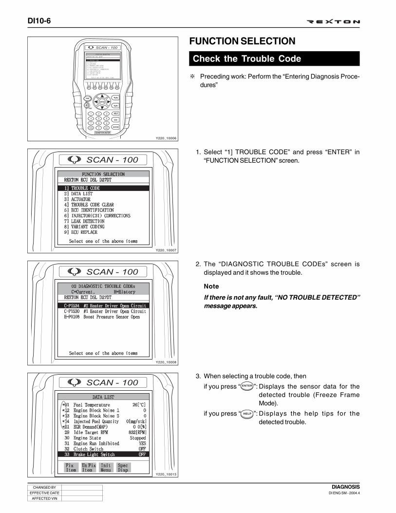
DI10-6
CHANGED BY
EFFECTIVE DATE
AFFECTED VIN
DIAGNOSISDI ENG SM - 2004.4
Y220_10006
Y220_10007
Y220_10008
Y220_10013
FUNCTION SELECTION
Check the Trouble Code
Preceding work: Perform the “Entering Diagnosis Proce-dures”
1. Select “1] TROUBLE CODE” and press “ENTER” in“FUNCTION SELECTION” screen.
2. The “DIAGNOSTIC TROUBLE CODEs” screen isdisplayed and it shows the trouble.
Note
If there is not any fault, “NO TROUBLE DETECTED”message appears.
3. When selecting a trouble code, then
if you press “ ”: Displays the sensor data for thedetected trouble (Freeze FrameMode).
if you press “ ”: Displays the help tips for thedetected trouble.

DI10-7
CHANGED BY
EFFECTIVE DATE
AFFECTED VIN
DIAGNOSISDI ENG SM - 2004.4
Y220_10010
Y220_10011
Y220_10012
Y220_10013
Sensor Data Check
Preceding Work: Perform the “Entering Diagnosis Proce-dures”
1. Select “2] DATA LIST” and press “ ” in “FUNCTIONSELECTION” screen.
2. The screen shows approx. 54 sensor data.
3. Select the items you want to see and press “ ” keyto freeze them.
Note
You can freeze up to 5 items (*: selected items).

DI10-8
CHANGED BY
EFFECTIVE DATE
AFFECTED VIN
DIAGNOSISDI ENG SM - 2004.4
Y220_10014
Y220_10015
Y220_10016
Y220_10017
Actuator Check
Preceding Work: Perform the “Entering Diagnosis Proce-dures”
1. Select “3] ACTUATOR” and press “ ” in “FUNCTIONSELECTION” screen.
2. The screen shows 14 items. Select the item you want tosee and press “ ”.
3. For example, if you select “02] GLOW PLUG” item andpress “ ”, the screen as shown in figure is displayed.
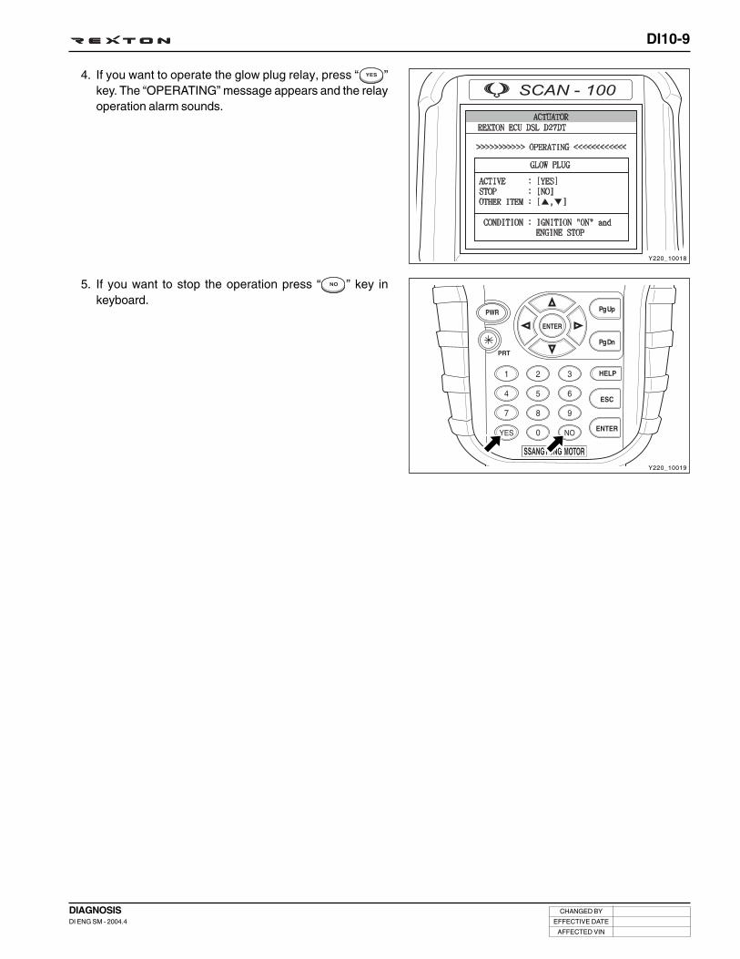
DI10-9
CHANGED BY
EFFECTIVE DATE
AFFECTED VIN
DIAGNOSISDI ENG SM - 2004.4
Y220_10019
Y220_10018
4. If you want to operate the glow plug relay, press “ ”key. The “OPERATING” message appears and the relayoperation alarm sounds.
5. If you want to stop the operation press “ ” key inkeyboard.
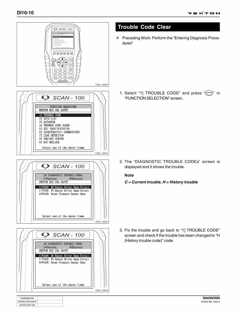
DI10-10
CHANGED BY
EFFECTIVE DATE
AFFECTED VIN
DIAGNOSISDI ENG SM - 2004.4
Y220_10020
Y220_10021
Y220_10022
Y220_10023
Trouble Code Clear
Preceding Work: Perform the “Entering Diagnosis Proce-dures”
1. Select “1] TROUBLE CODE” and press “ ” in“FUNCTION SELECTION” screen.
2. The “DIAGNOSTIC TROUBLE CODEs” screen isdisplayed and it shows the trouble.
Note
C = Current trouble, H = History trouble
3. Fix the trouble and go back to “1] TROUBLE CODE”screen and check if the trouble has been changed to “H(History trouble code)” code.

DI10-11
CHANGED BY
EFFECTIVE DATE
AFFECTED VIN
DIAGNOSISDI ENG SM - 2004.4
Y220_10024
Y220_10025
4. If the trouble has been change to “H (History trouble code)”code, press “ ” key to go back to “FUNCTIONSELECTION” screen. In this screen, select “4] TROUBLECODE CLEAR” and press “ ”.
5. The “TROUBLE CODE CLEAR” screen is displayed. Ifyou press “ ”, only the history trouble codes will becleared.
Note
• Current trouble codes will not be cleared.
• Check the trouble codes after clearing the troublecodes.

DI10-12
CHANGED BY
EFFECTIVE DATE
AFFECTED VIN
DIAGNOSISDI ENG SM - 2004.4
Y220_10027
Y220_10028
Y220_10029
Y220_10030
ECU Identification
Preceding Work: Perform the “Entering Diagnosis Proce-dures”
1. Select “1] ECU IDENTIFICATION” and press “ ” in“FUNCTION SELECTION” screen.
2. The “ECU IDENTIFICATION” screen that shows the VIN,ECU software number, ECU software version andprogramming date is displayed.
3. If you replaced the ECU, press “ ” to input the vehicleidentification number.

DI10-13
CHANGED BY
EFFECTIVE DATE
AFFECTED VIN
DIAGNOSISDI ENG SM - 2004.4
Y220_10031
Y220_10032
Y220_10033
Y220_10034
Injector Coding (C2I)
Preceding Work: Perform the “Entering Diagnosis Proce-dures”
Notice
If the injector/ECU has been replaced or the injector systemdefective is suspected, go to C2I Coding item and checkthe injector and coded injector C2I value.
1. Select “6] INJECTOR (C2I) CORRECTIONS” and press“ ” in “FUNCTION SELECTION” screen.
2. The “INJECTOR (C2I) CORRECTIONS” screen that showscurrent C2I coding values of #1 to #5 injector is displayed.
3. If you replaced the ECU, enter the C2I value of the relevantinjector.
Note
• The C2I value of replacing injector is recorded inthe label.
• C2I coding number: 16 digits (ex, B1 B9 D4 1B 43C6 0E 4F)

DI10-14
CHANGED BY
EFFECTIVE DATE
AFFECTED VIN
DIAGNOSISDI ENG SM - 2004.4
Y220_10035
Y220_10036
3-1. If you enter the invalid C2I value of the relevant injector,the message as shown in figure appears with alarm sound.
Note
If you want to go back to previous screen, press“ ” key. You can see the previous C2I value.
3-2. If you enter the valid C2I value of the relevant injector, themessage as shown in figure appears with alarm sound.

DI10-15
CHANGED BY
EFFECTIVE DATE
AFFECTED VIN
DIAGNOSISDI ENG SM - 2004.4
Y220_10037
Y220_10038
Y220_10040
Leak Detection
Preceding Work: Perform the “Entering Diagnosis Proce-dures”
Note
This item is for checking the high fuel pressure after theIMV supply line of HP pump in DI engine fuel system. Ifyou still suspect that the fuel pressure system is defectiveeven after no trouble is detected, perform the fuel pressuretest again by using a fuel pressure tool kit.
1. Select “7] LEAK DETECTION” and press “ ” in“FUNCTION SELECTION” screen.
2. The “LEAK DETECTION” screen that shows the checkingconditions as shown in figure is displayed.

DI10-16
CHANGED BY
EFFECTIVE DATE
AFFECTED VIN
DIAGNOSISDI ENG SM - 2004.4
Y220_10041
Y220_10042
Y220_10043
Y220_10044
Variant Coding
Preceding Work: Perform the “Entering Diagnosis Proce-dures”
1. Select “8] VARIANT CODING” and press “ ” in“FUNCTION SELECTION” screen.
2. When the “VARIANT CODING” screen is displayed,select “1] READ VARIANT VALUE” and press “ ”.
3. The “VARIANT CODING” screen that shows currentlyequipped devices is displayed.

DI10-17
CHANGED BY
EFFECTIVE DATE
AFFECTED VIN
DIAGNOSISDI ENG SM - 2004.4
Y220_10045
Y220_10046
Y220_10047
4. If you need to change the variant coding, press “ ”key to go back to “VARIANT CODING” screen. In thescreen, select “2] WRITE VARIANT CODING” and press“ ”.
5. When the “VARIANT CODING” screen is displayed,change the item by using arrow keys.
6. If you press “ ”, the message as shown in figureappears. And, then “VARIANT CODING” screen isdisplayed.
7. Select “READ VARIANT VALUE” to see the coding codedvalue.

DI10-18
CHANGED BY
EFFECTIVE DATE
AFFECTED VIN
DIAGNOSISDI ENG SM - 2004.4
Y220_10048
Y220_10049
Y220_10050
ECU Replace
Preceding Work: Perform the “Entering Diagnosis Proce-dures”
1. Select “9] ECU REPLACE” and press “ ” in“FUNCTION SELECTION” screen.
2. When the “ECU REPLACE (STEP 2)” screen is displayedfollowed by “ECU REPLACE (STEP 1) screen, turn theignition “OFF” and remove the currently installed ECU.
Notice
Do not turn off the Scan-100 at this time.Record the below data:
- Vehicle identification number- Variant coding value- C2I coding value- Multi calibration
3. Install the new ECU.

DI10-19
CHANGED BY
EFFECTIVE DATE
AFFECTED VIN
DIAGNOSISDI ENG SM - 2004.4
Y220_10051A
Y220_10052
Y220_10051
5. In “MULTI CALIBRATION SELECTION” screen, select “2]DOM/GEN” for automatic transmission equipped vehicleand select “4] DOM/GEN” for manual transmissionequipped vehicle.
4. If you turn the ignition switch to “ON” position and press “ ”, the message as shown in figure 1 (systeminitialization) appears, and then “MULTI CALIBRATION SELECTION” screen (fig. 2) is displayed.
6. When you press “ ”, the processing message asshown in figure appears.
figure 1 figure 2

DI10-20
CHANGED BY
EFFECTIVE DATE
AFFECTED VIN
DIAGNOSISDI ENG SM - 2004.4
Y220_10054
Y220_10055
Y220_10056
Y220_10053
7. If the multi calibration is completed successfully, “ECUREPLACE (STEP 5) screen is displayed.
Backup data:
- Multi calibration value
- VIN value
- Variant code value
- Injector (C2I) value
8. In immobilizer equipped vehicle, the immobilizer codingshould be done after completed the multi calibration.
9. Press “ ” and enter the user password.
10. If the password is invalid, the “access denied” screen asshown in figure is displayed.

DI10-21
CHANGED BY
EFFECTIVE DATE
AFFECTED VIN
DIAGNOSISDI ENG SM - 2004.4
Y220_10058
Y220_10057
Y220_10059
11. If the password is valid, an immobilizer coding is started.
12. If you want to code for additional keys, remove the firstkey from key switch and insert the second key. Turn itto “ON” position and press “ ” to proceed.
13. You can code up to five keys with same manner.
14. When the immobilizer coding is completed, press “ ”.The completion message as shown in figure appears.
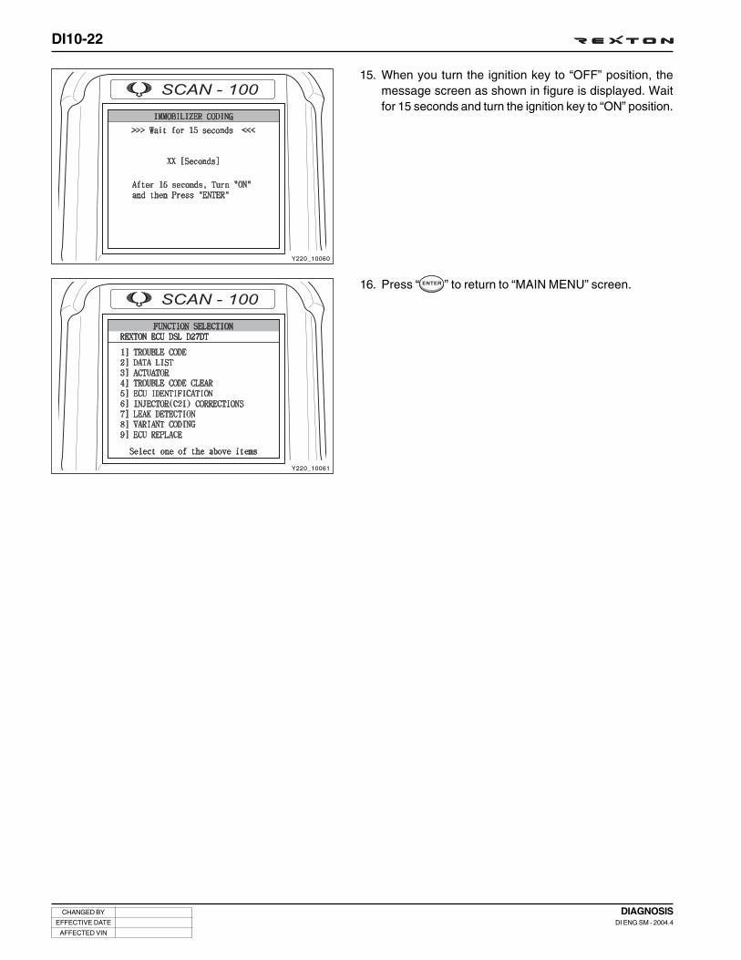
DI10-22
CHANGED BY
EFFECTIVE DATE
AFFECTED VIN
DIAGNOSISDI ENG SM - 2004.4
Y220_10060
Y220_10061
15. When you turn the ignition key to “OFF” position, themessage screen as shown in figure is displayed. Waitfor 15 seconds and turn the ignition key to “ON” position.
16. Press “ ” to return to “MAIN MENU” screen.

DI10-23
CHANGED BY
EFFECTIVE DATE
AFFECTED VIN
DIAGNOSISDI ENG SM - 2004.4
TROUBLE DIAGNOSIS TABLE
INDEX OF DTC .....................................................10D-24, 71
Trouble diagnosis table ......................................... 10D-27
Trouble diagnosis procedures ............................... 10D-75

DI10-24
CHANGED BY
EFFECTIVE DATE
AFFECTED VIN
DIAGNOSISDI ENG SM - 2004.4
INDEX OF DTCP0102
P0103
P0100
P0344
P0341
P0219
P0336
P0372
P1107
P1108
P1105
P0562
P0563
P0560
P0109
P0106
P0107
P0108
P0105
P1106
P1109
P0571
P1572
P1571
P1286
P1287
P1288
P1289
P1292
P1293
P1294
P1295
P1290
P1291
Low HFM Sensor Signal (Circuit Open) .......... DI10-27
High HFM Sensor Signal (Circuit Short) .......... DI10-27
Air Mass Flow (HFM) Malfunction .................. DI10-28
Cam Position Sensor Malfunction .................. DI10-28
Cam Position Sensor Malfunction
(Poor Synchronization) .................................. DI10-28
Too Small Clearance of Crank Angle Sensor .. DI10-28
Too Large Clearance of Crank Angle Sensor . DI10-29
Crank Angle Sensor Malfunction .................... DI10-29
Barometric Sensor Circuit Short/GND Short ... DI10-29
Barometric Sensor Circuit Short ..................... DI10-29
Barometric Sensor Circuit Short ..................... DI10-29
Low Battery Voltage ...................................... DI10-30
High Battery Voltage ...................................... DI10-30
Battery Voltage Malfunction ........................... DI10-30
Low Booster Pressure Sensor Signal ............ DI10-31
High Booster Pressure Sensor Signal ............ DI10-31
Booster Pressure Sensor Open/GND Short ... DI10-32
Booster Pressure Sensor Short ..................... DI10-32
Supply Voltage Fault to Booster
Pressure Sensor ............................................ DI10-33
Booster Pressure Sensor Malfunction ........... DI10-33
Booster Pressure Sensor Initial Check Fault . DI10-34
Brake Pedal Switch Fault ............................... DI10-34
Brake Lamp Signal Fault ................................. DI10-35
Brake Lamp Signal Fault ................................. DI10-35
Low Resistance for Injector #1 wiring harness . DI10-35
High Resistance for Injector #1 wiring harness .. DI10-36
Low Resistance for Injector #2 wiring harness . DI10-36
High Resistance for Injector #2 wiring harness .. DI10-36
Low Resistance for Injector #4 wiring harness . DI10-37
High Resistance for Injector #4 wiring harness .. DI10-37
Low Resistance for Injector #5 wiring harness . DI10-37
High Resistance for Injector #5 wiring harness .. DI10-38
Low Resistance for Injector #3 wiring harness . DI10-38
High Resistance for Injector #3 wiring harness .. DI10-38
P0704
P1115
P0118
P0117
P0115
P0685
P1405
P1406
P1480
P1481
P1482
P1526
P1527
P1528
P0325
P0330
P1611
P1612
P1618
P1619
P0263
P0266
P0272
P0275
P0269
P0201
P0202
P0204
P0205
Clutch switch malfunction ............................. DI10-38
Coolant Temperature Sensor Malfunction ....... DI10-39
Coolant Temperature Sensor
Malfunction - Short ........................................ DI10-39
Coolant Temperature Sensor
Malfunction - Open ........................................ DI10-40
Supply Voltage Fault to Coolant
Temperature Sensor ...................................... DI10-40
Main Relay Malfunction .................................. DI10-40
EGR Solenoid Valve Short Malfunction - Short .. DI10-40
EGR Solenoid Valve Malfunction - Short ........ DI10-40
Condenser Fan #1 Circuit Malfunction - Open . DI10-41
Condenser Fan #1 Circuit Malfunction - Short . DI10-41
Condenser Fan #1 Circuit Malfunction -
Short to Ground ............................................. DI10-41
Condenser Fan #2 Circuit Malfunction - Open . DI10-41
Condenser Fan #2 Circuit Malfunction - Short . DI10-41
Condenser Fan #2 Circuit Malfunction -
Short to Ground ............................................. DI10-41
Accelerometer #1 (Knock Sensor)
Malfunction .................................................... DI10-42
Accelerometer #2 (Knock Sensor)
Malfunction .................................................... DI10-42
Injector Bank #1 Malfunction - Low Voltage ... DI10-42
Injector Bank #1 Malfunction - High Voltage ... DI10-43
Injector Bank #2 Malfunction - Low Voltage ... DI10-43
Injector Bank #2 Malfunction - High Voltage .. DI10-43
Injector #1 Balancing Fault ............................. DI10-44
Injector #2 Balancing Fault ............................. DI10-44
Injector #4 Balancing Fault ............................. DI10-44
Injector #5 Balancing Fault ............................. DI10-44
Injector #3 Balancing Fault ............................. DI10-44
Injector #1 Circuit Open .................................. DI10-44
Injector #2 Circuit Open ................................. DI10-44
Injector #4 Circuit Open .................................. DI10-45
Injector #5 Circuit Open .................................. DI10-45

DI10-25
CHANGED BY
EFFECTIVE DATE
AFFECTED VIN
DIAGNOSISDI ENG SM - 2004.4
P0203
P1201
P1202
P1204
P1205
P1203
P0182
P0183
P0180
P1678
P1679
P1680
P1530
P1531
P1532
P1534
P1535
P1536
P1254
P1253
P1256
P1257
P1258
P1259
P1191
P0255
P0251
P0253
P0113
P0112
Injector #3 Circuit Open .................................. DI10-45
Injector #1 Circuit Short .................................. DI10-45
Injector #2 Circuit Short .................................. DI10-45
Injector #4 Circuit Short .................................. DI10-45
Injector #5 Circuit Short .................................. DI10-45
Injector #3 Circuit Short .................................. DI10-46
Fuel temperature sensor - Short to Ground ... DI10-46
Fuel temperature sensor - Short to B+ ........... DI10-46
Fuel temperature sensor - Malfunction .......... DI10-47
Glow Plug Malfunction - Open ...................... DI10-47
Glow Plug Malfunction - Short ...................... DI10-47
Glow Plug Malfunction - Short to Ground ...... DI10-47
#1 Heater operating circuit - Open ................ DI10-47
#1 Heater operating circuit - Short ................ DI10-48
#1 Heater operating circuit - Short to Ground . DI10-48
#2 Heater operating circuit - Open ................ DI10-48
#2 Heater operating circuit - Short ................. DI10-48
#2 Heater operating circuit - Short to Ground DI10-48
Maximum Rail Pressure Control Malfunction
(IMV Fault) .................................................... DI10-49
Minimum Rail Pressure Control Malfunction
(IMV Fault) .................................................... DI10-49
Too Small Transfer Pressure Fuel in
Rail Pressure System ..................................... DI10-50
Too Large Transfer Pressure Fuel in
Rail Pressure System ..................................... DI10-50
Too Small High Pressure Fuel in
Rail Pressure System .................................... DI10-51
Too Large High Pressure Fuel in
Rail Pressure System .................................... DI10-51
Pressure Build Up - Too Slow ....................... DI10-52
IMV Driver Circuit Malfunction - Open ........... DI10-52
IMV Driver Circuit Malfunction - Short ........... DI10-52
IMV Driver Circuit Malfunction -
Short to Ground ............................................ DI10-52
Intake Air Temperature Circuit Malfunction -
Short .............................................................. DI10-53
Intake Air Temperature Circuit Malfunction -
Open ............................................................. DI10-54
P0110
P1171
P1172
P1174
P1175
P1173
P1252
P1120
P1121
P1122
P1123
P1124
P0122
P0123
P0120
P0222
P0223
P0220
P0192
P0193
P0190
P0191
P1192
P1193
P1190
P0215
P1500
P0642
Intake Air Temperature Circuit Malfunction -
Source Power Problem .................................. DI10-55
#1 Injector MDP Malfunction ........................... DI10-55
#2 Injector MDP Malfunction ........................... DI10-55
#4 Injector MDP Malfunction ........................... DI10-55
#5 Injector MDP Malfunction ........................... DI10-55
#3 Injector MDP Malfunction ........................... DI10-55
Too High IMV Pressure ................................... DI10-56
Accelerator Pedal Sensor #1 Malfunction ..... DI10-56
Accelerator Pedal Sensor #2 Malfunction ..... DI10-56
Accelerator Pedal Sensor Malfunction
(Limp Home Mode) ......................................... DI10-56
Accelerator Pedal Sensor Malfunction
(Torque Mode) ............................................... DI10-57
Accelerator Pedal Sensor Malfunction - Stuck .. DI10-57
Accelerator Pedal Sensor #1 Malfunction -
Open .............................................................. DI10-57
Accelerator Pedal Sensor #1 Malfunction -
Short .............................................................. DI10-57
Accelerator Pedal Sensor #1 Malfunction -
Supply Voltage Fault ...................................... DI10-57
Accelerator Pedal Sensor #2 Malfunction -
Open .............................................................. DI10-58
Accelerator Pedal Sensor #2 Malfunction -
Short .............................................................. DI10-58
Accelerator Pedal Sensor #2 Malfunction -
Supply Voltage Fault ...................................... DI10-58
Fuel Rail Pressure Sensor Malfunction - Open .. DI10-58
Fuel Rail Pressure Sensor Malfunction - Short .. DI10-59
Supply Voltage Fault to
Fuel Rail Pressure Sensor .............................. DI10-59
Fuel Rail Pressure Sensor Signal Fault .......... DI10-59
Fuel Rail Pressure Sensor Initial Signal Fault -
Low ............................................................... DI10-60
Fuel Rail Pressure Sensor Initial Signal Fault -
High ............................................................... DI10-60
Fuel Rail Pressure Sensor Initial Signal Fault .. DI10-60
Main Relay Fault - Stuck ................................. DI10-61
Vehicle Speed Fault ....................................... DI10-61
ECU Supply Voltage 1 Fault - Low (5 V) ........ DI10-61

DI10-26
CHANGED BY
EFFECTIVE DATE
AFFECTED VIN
DIAGNOSISDI ENG SM - 2004.4
P0643
P0641
P0652
P0653
P0651
P0698
P0699
P0697
P0245
P0246
P0606
P1607
P1600
P1601
P1602
P1614
P1615
P1616
P1606
P1620
P1621
P1622
P1603
P1604
P1605
P1148
P0400
P1235
P1608
P0335
P1170
P1676
P1677
P0671
P0672
P0673
P0674
P0675
P1671
ECU Supply Voltage 1 Fault - High (5 V) ........ DI10-61
ECU Supply Voltage 1 Fault (5 V) ................... DI10-61
ECU Supply Voltage 2 Fault - Low (5 V) ........ DI10-62
ECU Supply Voltage 2 Fault - High (5 V) ........ DI10-62
ECU Supply Voltage 2 Fault (5 V) ................... DI10-62
ECU Supply Voltage Fault - Low (2.5 V) ........ DI10-62
ECU Supply Voltage Fault - High (2.5 V) ........ DI10-62
ECU Supply Voltage Fault (2.5 V) ................... DI10-63
Turbo Charger Actuator Circuit Fault - Short .. DI10-63
Turbo Charger Actuator Circuit Fault -
Short to B+..................................................... DI10-63
ECU Watchdog Fault ...................................... DI10-63
ECU Injector Cut Fault ..................................... DI10-63
ECU Shut Down Fault ..................................... DI10-63
ECU Fault ....................................................... DI10-63
ECU Fault ....................................................... DI10-63
ECU C2I/MDP Fault ......................................... DI10-64
ECU Fault ....................................................... DI10-64
ECU Fault ....................................................... DI10-64
ECU Fault ....................................................... DI10-64
ECU Fault ....................................................... DI10-64
ECU Fault ....................................................... DI10-64
ECU Fault ....................................................... DI10-64
ECU Fault ....................................................... DI10-64
ECU Fault ....................................................... DI10-64
ECU Fault ....................................................... DI10-64
Accelerometer (Knock Sensor) Learning Fault . DI10-64
EGR Control Valve Fault ................................. DI10-65
VGT Operation Fault ...................................... DI10-65
ECU Fault ....................................................... DI10-65
No Crank Signals ............................................ DI10-65
Torque Trim Fault - High ................................. DI10-65
Glow Plug Communication Fault ..................... DI10-65
Glow Plug Controller Fault .............................. DI10-65
#1 Glow Plug Fault - Open ............................. DI10-66
#2 Glow Plug Fault - Open ............................. DI10-66
#3 Glow Plug Fault - Open ............................. DI10-66
#4 Glow Plug Fault - Open ............................. DI10-66
#5 Glow Plug Fault - Open ............................. DI10-66
#1 Glow Plug Fault - Short (+B) ..................... DI10-66
#2 Glow Plug Fault - Short (B+) ..................... DI10-67
#3 Glow Plug Fault - Short (B+) ..................... DI10-67
#4 Glow Plug Fault - Short (B+) ..................... DI10-67
#5 Glow Plug Fault - Short (B+) ..................... DI10-67
TCU Signal Fault ............................................. DI10-67
Air Conditioner Operating Circuit Fault - Open . DI10-67
Air Conditioner Operating Circuit Fault - Short . DI10-67
Air Conditioner Operating Circuit Fault -
Short to Ground ............................................. DI10-67
Too High Water Level in Fuel Filter ................. DI10-68
Immobilizer Fault (refer to immobilizer section) .. DI10-68
No response from Immobilizer
(refer to immobilizer section) ......................... DI10-68
Wrong response from Immobilizer
(refer to immobilizer section) ......................... DI10-68
Immobilizer Fault (refer to immobilizer section) . DI10-68
Immobilizer Fault (refer to immobilizer section) . DI10-68
Immobilizer Fault (refer to immobilizer section) . DI10-69
Immobilizer Fault (refer to immobilizer section) . DI10-69
Immobilizer Fault (refer to immobilizer section) . DI10-69
P1672
P1673
P1674
P1675
P0700
P1540
P1541
P1542
P1149
P1634
P1635
P1630
P1631
P1632
P1633
P0633
P1636

DI10-27
CHANGED BY
EFFECTIVE DATE
AFFECTED VIN
DIAGNOSISDI ENG SM - 2004.4
TROUBLE DIAGNOSIS TABLE
DTC TroubleLimpHomeMode
ImmediatelyEngineStop
DelayedEngineStop
TorqueReduction(max.20%)
HelpTorque
Reduction(max.50%)
P0102
P0103
Low HFM Sensor Signal(Circuit Open)
High HFM Sensor Signal(Circuit Short)
- HFM sensing values are lower thanminimum sensing values.
- Check the resistance in HFM sensor.
- Check the ECU wiring harness (openand poor contact).
• Check the ECU pin #82 and #84 foropen circuit.
- Actual air mass flow vs. Outputvoltages.
• -20 Kg/h: 0.47 V
• 0 Kg/h: 0.99 V
• 10 Kg/h: 1.2226 ~ 1.2398 V
• 15 Kg/h: 1.3552 ~ 1.3778 V
• 30 Kg/h: 1.6783 ~ 1.7146 V
• 60 Kg/h: 2.1619 ~ 2.2057 V
• 120 Kg/h: 2.7215 ~ 2.7762 V
• 250 Kg/h: 3.4388 ~ 3.5037 V
• 370 Kg/h: 3.8796 ~ 3.9511 V
• 480 Kg/h: 4.1945 ~ 4.2683 V
• 640 Kg/h: 4.5667 ~ 4.6469 V
- Replace the ECU if required.
- HFM sensing values are higher thanmaximum sensing values.
- Check the resistance in HFM sensor.
- Check the ECU wiring harness (openand poor contact).
• Check the ECU pin #82 and #84 foropen circuit.
- Actual air mass flow vs. Outputvoltages.
• -20 Kg/h: 0.47 V
• 0 Kg/h: 0.99 V
• 10 Kg/h: 1.2226 ~ 1.2398 V
• 15 Kg/h: 1.3552 ~ 1.3778 V
• 30 Kg/h: 1.6783 ~ 1.7146 V
• 60 Kg/h: 2.1619 ~ 2.2057 V
• 120 Kg/h: 2.7215 ~ 2.7762 V
• 250 Kg/h: 3.4388 ~ 3.5037 V
• 370 Kg/h: 3.8796 ~ 3.9511 V
• 480 Kg/h: 4.1945 ~ 4.2683 V
• 640 Kg/h: 4.5667 ~ 4.6469 V
- Replace the ECU if required.

DI10-28
CHANGED BY
EFFECTIVE DATE
AFFECTED VIN
DIAGNOSISDI ENG SM - 2004.4
DTC TroubleLimpHomeMode
ImmediatelyEngineStop
DelayedEngineStop
TorqueReduction(max.20%)
HelpTorque
Reduction(max.50%)
P0100
P0344
P0341
P0219
Air Mass Flow (HFM) Mal-function
Cam Position Sensor Mal-function
Cam Position Sensor Malfunc-tion (Poor Synchronization)
Too Small Clearance ofCrank Angle Sensor
- The external power supply is faulty.
• Check the external power supply.
• Check the sensor wiring harness(open, short, poor contact).
- Actual air mass flow vs. Outputvoltages.
• -20 Kg/h: 0.47 V
• 0 Kg/h: 0.99 V
• 10 Kg/h: 1.2226 ~ 1.2398 V
• 15 Kg/h: 1.3552 ~ 1.3778 V
• 30 Kg/h: 1.6783 ~ 1.7146 V
• 60 Kg/h: 2.1619 ~ 2.2057 V
• 120 Kg/h: 2.7215 ~ 2.7762 V
• 250 Kg/h: 3.4388 ~ 3.5037 V
• 370 Kg/h: 3.8796 ~ 3.9511 V
• 480 Kg/h: 4.1945 ~ 4.2683 V
• 640 Kg/h: 4.5667 ~ 4.6469 V
- Replace the ECU if required.
- No cam recognition signal (missingevents).
- Check the source voltage of cam posi-tion sensor (ECU pin #111) (specifiedvalue: 4.5 ~ 12 V).
- Check the sensor wiring harness forECU pin #103 and #104 (open, short,poor contact).
- Check the cam position sensor.
- Measure the air gap: 0.2 ~ 1.8 mm
- Replace the ECU if required.
- Not synchronized with Crank anglesignal.
- Check the source voltage of cam posi-tion sensor (specified value: 4.5 ~ 12 V).
- Check the sensor wiring harness forECU pin #103 and #104 (open, short,poor contact).
- Check the cam position sensor.
- Measure the air gap: 0.2 ~ 1.8 mm
- Replace the ECU if required.
- Crank angle signal faults or clearancetoo close.
- Check the sensor wiring harness forECU pin #90 and #82 (open, short, poorcontact).
- Check the resistance of crank anglesensor: 1090 Ω ± 15 %.
- Measure the air gap: 0.3 ~ 1.3 mm
• 1.3 mm of air gap: outputs 1.0 V at40 rpm
• 0.3 mm of air gap: outputs 150 V at7000 rpm
- Check the teeth condition.
• Drive plate (A/T), DMF (M/T)
- Replace the ECU if required.

DI10-29
CHANGED BY
EFFECTIVE DATE
AFFECTED VIN
DIAGNOSISDI ENG SM - 2004.4
DTC TroubleLimpHomeMode
ImmediatelyEngineStop
DelayedEngineStop
TorqueReduction(max.20%)
HelpTorque
Reduction(max.50%)
P0336
P0372
P1107
P1108
P1105
Too Large Clearance ofCrank Angle Sensor
Crank Angle Sensor Mal-function
Barometric Sensor CircuitShort/GND Short
Barometric Sensor CircuitShort
Barometric Sensor CircuitShort
- Air gap of crank angle sensor isabnormal.
- Check the sensor wiring harness forECU pin #90 and #82 (open, short, poorcontact).
- Check the resistance of crank anglesensor: 1090 Ω ± 15 %.
- Measure the air gap: 0.3 ~ 1.3 mm
• 1.3 mm of air gap: outputs 1.0 V at40 rpm
• 0.3 mm of air gap: outputs 150 V at7000 rpm
- Check the teeth condition.
• Drive plate (A/T), DMF (M/T)
- Replace the ECU if required.
- Even though cam position recognitionis normal, no crank angle signal recog-nition (missing tooth).
- Check the sensor wiring harness forECU pin #90 and #82 (open, short, poorcontact).
- Check the resistance of crank anglesensor: 1090 Ω ± 15 %.
- Measure the air gap: 0.3 ~ 1.3 mm
• 1.3 mm of air gap: outputs 1.0 V at40 rpm
• 0.3 mm of air gap: outputs 150 V at7000 rpm
- Check the teeth condition.
• Drive plate (A/T), DMF (M/T)
- Replace the ECU if required.
- Out of range about barometric sensor(short to ground).
- Actual barometric pressure vs. Outputvoltages.
• 15 Kpa: 0 V 35 Kpa: 1.0 V
• 55 Kpa: 2.0 V 80 Kpa: 3.0 V
• 100 Kpa: 4.0 V 110 Kpa: 4.5 V
- Replace the ECU.
- Out of range about barometric sensor(short to B+).
- Actual barometric pressure vs. Outputvoltages.
• 15 Kpa: 0 V 35 Kpa: 1.0 V
• 55 Kpa: 2.0 V 80 Kpa: 3.0 V
• 100 Kpa: 4.0 V 110 Kpa: 4.5 V
- Replace the ECU.
- Out of range about barometric sensor(over voltage).
- Actual barometric pressure vs. Outputvoltages.
• 15 Kpa: 0 V 35 Kpa: 1.0 V
• 55 Kpa: 2.0 V 80 Kpa: 3.0 V
• 100 Kpa: 4.0 V 110 Kpa: 4.5 V
- Replace the ECU.

DI10-30
CHANGED BY
EFFECTIVE DATE
AFFECTED VIN
DIAGNOSISDI ENG SM - 2004.4
DTC TroubleLimpHomeMode
ImmediatelyEngineStop
DelayedEngineStop
TorqueReduction(max.20%)
HelpTorque
Reduction(max.50%)
P0562
P0563
P0560
Low Battery Voltage
High Battery Voltage
Battery Voltage Malfunc-tion
O
O
O
- Malfunction in recognition of systemsource voltage (Lower than threshold).
• Less than minimum 8 Volts in 2000rpm below
• Less than 10 Volts in 2000 rpm above.
- Check the battery wiring harness forECU pin #3, #4 and #5 (open, short,poor contact).
- Check the battery main relay and fuse.
- Check the body ground.
- Measure the resistance between bodyground and ECU ground.
• Repair the ECU ground if the resis-tance is high.
- Replace the ECU if required.
- Malfunction in recognition of systemsource voltage (Higher than threshold).
• More than minimum 16 Volts in 2000rpm below
- Check the battery wiring harness forECU pin #3, #4 and #5 (open, short,poor contact).
- Check the alternator.
- Check the body ground.
- Measure the resistance between bodyground and ECU ground.
• Repair the ECU ground if the resis-tance is high.
- Replace the ECU if required.
- Malfunction in recognition of systemsource voltage (A/D converter faults).
• Less than minimum 8 Volts in 2000rpm below
• Less than 10 Volts in 2000 rpm above.
- Check the battery wiring harness forECU pin #3, #4 and #5 (open, short,poor contact).
- Check the battery main relay and fuse.
- Check the body ground.
- Measure the resistance between bodyground and ECU ground.
• Repair the ECU ground if the resis-tance is high.
- Replace the ECU if required.

DI10-31
CHANGED BY
EFFECTIVE DATE
AFFECTED VIN
DIAGNOSISDI ENG SM - 2004.4
DTC TroubleLimpHomeMode
ImmediatelyEngineStop
DelayedEngineStop
TorqueReduction(max.20%)
HelpTorque
Reduction(max.50%)
P0109
P0106
Low Booster PressureSensor Signal
High Booster PressureSensor Signal
- Out of signal range about boost pres-sure sensor at Ignition key-On and En-gine Stop (Lower than specified values).
- Check the supply voltage to sensor.
- Actual boost pressure vs. Outputvoltages.
• Raw Signal Range: 0.545 ~ 2.490 bar
• 0.4 bar: 0.6120 V
• 1.4 bar: 2.6520 V
• 2.4 bar: 4.6920 V
- Check the sensor wiring harness for ECUpin #99 and #100 (open, poor contact).
- Visually check sensor and replace ifrequired.
- Replace the ECU if required.
- Check whether existing or not aboutturbo boosting control malfunction(P1235) simultaneously.
- If there is turbo boost control fault,Should be checked followings also;
• Leakage before turbo system
• Vacuum pump malfunction
• Waste gate’ solenoid valve
• Turbo charger system defect or mal-function itself
• Air inlet restriction
• Exhaust system restriction
- Out of signal range about boost pres-sure sensor at Ignition key-On and En-gine Stop (Higher than specifiedvalues).
- Check the supply voltage to sensor.
- Actual boost pressure vs. Outputvoltages.
• Raw Signal Range: 0.545 ~ 2.490 bar
• 0.4 bar: 0.6120 V
• 1.4 bar: 2.6520 V
• 2.4 bar: 4.6920 V
- Check the sensor wiring harness forECU pin #99 and #100 (open, poorcontact).
- Visually check sensor and replace ifrequired.
- Replace the ECU if required.
- Check whether existing or not aboutturbo boosting control malfunction(P1235) simultaneously.
- If there is turbo boost control fault,Should be checked followings also;
• Leakage before turbo system
• Vacuum pump malfunction
• Waste gate’ solenoid valve
• Turbo charger system defect ormalfunction itself
• Air inlet restriction
• Exhaust system restriction

DI10-32
CHANGED BY
EFFECTIVE DATE
AFFECTED VIN
DIAGNOSISDI ENG SM - 2004.4
DTC TroubleLimpHomeMode
ImmediatelyEngineStop
DelayedEngineStop
TorqueReduction(max.20%)
HelpTorque
Reduction(max.50%)
P0107
P0108
Booster Pressure SensorOpen/GND Short
Booster Pressure SensorShort
- Out of signal range about boost pres-sure sensor at Engine running condi-tion (Lower than specified values).
- Check the supply voltage to sensor.
- Actual boost pressure vs. Output volt-ages
• Raw Signal Range: 0.545 ~ 2.490 bar
• 0.4 bar: 0.6120 V
• 1.4 bar: 2.6520 V
• 2.4 bar: 4.6920 V
- Check the sensor wiring harness forECU pin #99 and #100 (open, poorcontact).
- Visually check sensor and replace ifrequired.
- Replace the ECU if required.
- Check whether existing or not aboutturbo boosting control malfunction(P1235) simultaneously.
- If there is turbo boost control fault,Should be checked followings also;
• Leakage before turbo system
• Vacuum pump malfunction
• Waste gate’ solenoid valve
• Turbo charger system defect or mal-function itself
• Air inlet restriction
• Exhaust system restriction
- Out of signal range about boost pres-sure sensor at Engine running condi-tion (Higher than specified values).
- Check the supply voltage to sensor.
- Actual boost pressure vs. Output volt-ages
• Raw Signal Range: 0.545~2.490 bar
• 0.4 bar: 0.6120 V
• 1.4 bar: 2.6520 V
• 2.4 bar: 4.6920 V
- Check the sensor wiring harness forECU pin #99 and #100 (open, poorcontact).
- Visually check sensor and replace ifrequired.
- Replace the ECU if required.
- Check whether existing or not aboutturbo boosting control malfunction(P1235) simultaneously.
- If there is turbo boost control fault,Should be checked followings also;
• Leakage before turbo system
• Vacuum pump malfunction
• Waste gate’ solenoid valve
• Turbo charger system defect ormalfunction itself
• Air inlet restriction
• Exhaust system restriction

DI10-33
CHANGED BY
EFFECTIVE DATE
AFFECTED VIN
DIAGNOSISDI ENG SM - 2004.4
DTC TroubleLimpHomeMode
ImmediatelyEngineStop
DelayedEngineStop
TorqueReduction(max.20%)
HelpTorque
Reduction(max.50%)
P0105
P1106
Supply Voltage Fault toBooster Pressure Sensor
Booster Pressure SensorMalfunction
- Out of range of supply voltages aboutboost pressure sensor at Ignition key-On and Engine Stop (Higher than speci-fied values).
- Check the supply voltage to sensor.
- Actual boost pressure vs. Output voltages
• Raw Signal Range: 0.545 ~ 2.490 bar
• 0.4 bar: 0.6120 V
• 1.4 bar: 2.6520 V
• 2.4 bar: 4.6920 V
- Check the sensor wiring harness forECU pin #100 and #108 (open, poorcontact).
- Visually check sensor and replace ifrequired.
- Replace the ECU if required.
- Check whether existing or not aboutturbo boosting control malfunction(P1235) simultaneously.
- If there is turbo boost control fault,Should be checked followings also;
• Leakage before turbo system
• Vacuum pump malfunction
• Waste gate’ solenoid valve
• Turbo charger system defect or mal-function itself
• Air inlet restriction
• Exhaust system restriction
- Out of range of supply voltages aboutboost pressure sensor at Ignition key-On and Engine Stop (Higher than speci-fied values).
- Check the supply voltage to sensor.
- Actual boost pressure vs. Output voltages.
• Raw Signal Range: 0.545 ~ 2.490 bar
• 0.4 bar: 0.6120 V
• 1.4 bar: 2.6520 V
• 2.4 bar: 4.6920 V
- Check the sensor wiring harness forECU pin #99 and #100 (open, poorcontact).
- Visually check sensor and replace ifrequired.
- Replace the ECU if required.
- Check whether existing or not aboutturbo boosting control malfunction(P1235) simultaneously.
- If there is turbo boost control fault,Should be checked followings also;
• Leakage before turbo system
• Vacuum pump malfunction
• Waste gate’ solenoid valve
• Turbo charger system defect ormalfunction itself
• Air inlet restriction
• Exhaust system restriction

DI10-34
CHANGED BY
EFFECTIVE DATE
AFFECTED VIN
DIAGNOSISDI ENG SM - 2004.4
DTC TroubleLimpHomeMode
ImmediatelyEngineStop
DelayedEngineStop
TorqueReduction(max.20%)
HelpTorque
Reduction(max.50%)
P1109
P0571
Booster Pressure SensorInitial Check Fault
Brake Pedal Switch Fault
- Implausible signal values or range aboutboost pressure sensor at Engine run-ning condition (Higher than specifiedvalues).
- Check the supply voltage to sensor.
- Actual boost pressure vs. Output volt-ages
• Raw Signal Range: 0.545 ~ 2.490 bar
• 0.4 bar: 0.6120 V
• 1.4 bar: 2.6520 V
• 2.4 bar: 4.6920 V
- Check the sensor wiring harness forECU pin #99 and #100 (open, poorcontact).
- Visually check sensor and replace ifrequired.
- Replace the ECU if required.
- Check whether existing or not aboutturbo boosting control malfunction(P1235) simultaneously.
- If there is turbo boost control fault,Should be checked followings also;
• Leakage before turbo system
• Vacuum pump malfunction
• Waste gate’ solenoid valve
• Turbo charger system defect or mal-function itself
• Air inlet restriction
• Exhaust system restriction
- The brake pedal switch or light switchis faulty.
• Brake pedal switch: Normal Close(NC)
• Light switch: Normal Open (NO)
• When operating the brake switch,one signal (NO) is sent to autocruise and the other (NC) is sent tobrake lamp.
- Check the brake and light switch wir-ing harness.
- Check the supply voltage to brake andlight switch (12 V).
- Check the brake and light switch forcontact.
- Check the ECU wiring harness for ECUpin #77 and #58 (short, poor contact).
- Replace the ECU if required.

DI10-35
CHANGED BY
EFFECTIVE DATE
AFFECTED VIN
DIAGNOSISDI ENG SM - 2004.4
DTC TroubleLimpHomeMode
ImmediatelyEngineStop
DelayedEngineStop
TorqueReduction(max.20%)
HelpTorque
Reduction(max.50%)
P1572
P1571
P1286
Brake Lamp Signal Fault
Brake Lamp Signal Fault
Low Resistance for Injec-tor #1 wiring harness
- The brake pedal switch or light switchis faulty.
• Brake pedal switch: Normal Close(NC)
• Light switch: Normal Open (NO)
• When operating the brake pedalswitch, one signal (NO) is sent toauto cruise and the other (NC) issent to brake lamp.
- Check the brake pedal and light switchwiring harness.
- Check the supply voltage to brake pedaland light switch (12 V).
- Check the brake pedal and light switchfor contact.
- Check the ECU wiring harness for ECUpin #58 (open, short, poor contact).
- Replace the ECU if required.
- The brake pedal switch is faulty.
• Brake pedal switch: Normal Close(NC)
• Light switch: Normal Open (NO)
• When operating the brake pedalswitch, one signal (NO) is sent toauto cruise and the other (NC) issent to brake lamp.
- Check the brake pedal switch wiringharness.
- Check the supply voltage to brake pedalswitch (12 V).
- Check the brake pedal switch forcontact.
- Check the ECU wiring harness for ECUpin #77 (open, short, poor contact).
- Replace the ECU if required.
- Out of range about wiring harness re-sistance for Injector #1.
• Low: Less than 0.150 Ω (injectorcircuit open)
- Check the injector #1 wiring harnessand electric isolation.
- Check the injector #1 wiring harnessfor open circuit.
• If the pin in injector #1 is defective,replace injector #1 and perform C2Icoding, then check again.
• If the pin in injector #1 is notdefective, check the ECU wiringharness.
- Replace the ECU if required.

DI10-36
CHANGED BY
EFFECTIVE DATE
AFFECTED VIN
DIAGNOSISDI ENG SM - 2004.4
DTC TroubleLimpHomeMode
ImmediatelyEngineStop
DelayedEngineStop
TorqueReduction(max.20%)
HelpTorque
Reduction(max.50%)
P1287
P1288
P1289
High Resistance for Injec-tor #1 wiring harness
Low Resistance for Injec-tor #2 wiring harness
High Resistance for Injec-tor #2 wiring harness
- Out of range about wiring harness re-sistance for Injector #1.
• High: More than 0.573 Ω (injectorcircuit short)
- Check the injector #1 wiring harnessand electric isolation.
- Check the injector #1 wiring harnessfor short circuit.
• If the trouble still exists after remov-ing the injector connector, replaceinjector #1 and perform C2I coding,then check again.
• If the trouble is fixed after removingthe injector connector, check thewiring harness between ECU andinjector.
- Replace the ECU if required.
- Out of range about wiring harness re-sistance for Injector #2.
• Low: Less than 0.150 Ω (injectorcircuit open)
- Check the injector #2 wiring harnessand electric isolation.
- Check the injector #2 wiring harnessfor open circuit.
• If the pin in injector #2 is defective,replace injector #2 and perform C2Icoding, then check again.
• If the pin in injector #2 is notdefective, check the ECU wiringharness.
- Replace the ECU if required.
- Out of range about wiring harness re-sistance for Injector #2.
• High: More than 0.573 Ω (injectorcircuit short)
- Check the injector #2 wiring harnessand electric isolation.
- Check the injector #2 wiring harnessfor short circuit.
• If the trouble still exists after remov-ing the injector connector, replaceinjector #2 and perform C2I coding,then check again.
• If the trouble is fixed after removingthe injector connector, check thewiring harness between ECU andinjector.
- Replace the ECU if required.
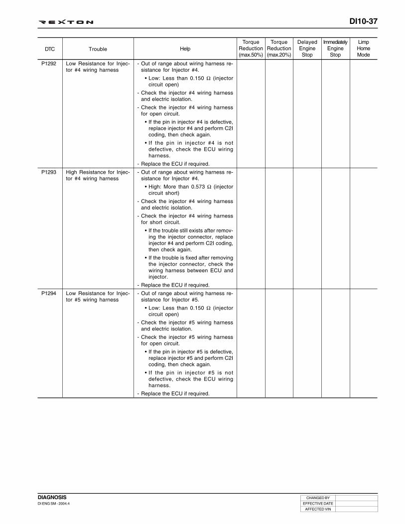
DI10-37
CHANGED BY
EFFECTIVE DATE
AFFECTED VIN
DIAGNOSISDI ENG SM - 2004.4
DTC TroubleLimpHomeMode
ImmediatelyEngineStop
DelayedEngineStop
TorqueReduction(max.20%)
HelpTorque
Reduction(max.50%)
P1292
P1293
P1294
Low Resistance for Injec-tor #4 wiring harness
High Resistance for Injec-tor #4 wiring harness
Low Resistance for Injec-tor #5 wiring harness
- Out of range about wiring harness re-sistance for Injector #4.
• Low: Less than 0.150 Ω (injectorcircuit open)
- Check the injector #4 wiring harnessand electric isolation.
- Check the injector #4 wiring harnessfor open circuit.
• If the pin in injector #4 is defective,replace injector #4 and perform C2Icoding, then check again.
• If the pin in injector #4 is notdefective, check the ECU wiringharness.
- Replace the ECU if required.
- Out of range about wiring harness re-sistance for Injector #4.
• High: More than 0.573 Ω (injectorcircuit short)
- Check the injector #4 wiring harnessand electric isolation.
- Check the injector #4 wiring harnessfor short circuit.
• If the trouble still exists after remov-ing the injector connector, replaceinjector #4 and perform C2I coding,then check again.
• If the trouble is fixed after removingthe injector connector, check thewiring harness between ECU andinjector.
- Replace the ECU if required.
- Out of range about wiring harness re-sistance for Injector #5.
• Low: Less than 0.150 Ω (injectorcircuit open)
- Check the injector #5 wiring harnessand electric isolation.
- Check the injector #5 wiring harnessfor open circuit.
• If the pin in injector #5 is defective,replace injector #5 and perform C2Icoding, then check again.
• If the pin in injector #5 is notdefective, check the ECU wiringharness.
- Replace the ECU if required.

DI10-38
CHANGED BY
EFFECTIVE DATE
AFFECTED VIN
DIAGNOSISDI ENG SM - 2004.4
DTC TroubleLimpHomeMode
ImmediatelyEngineStop
DelayedEngineStop
TorqueReduction(max.20%)
HelpTorque
Reduction(max.50%)
P1295
P1290
P1291
P0704
High Resistance for Injec-tor #5 wiring harness
Low Resistance for Injec-tor #3 wiring harness
High Resistance for Injec-tor #3 wiring harness
Clutch switch malfunction
- Out of range about wiring harness re-sistance for Injector #5.
• High: More than 0.573 Ω (injectorcircuit short)
- Check the injector #5 wiring harnessand electric isolation.
- Check the injector #5 wiring harnessfor short circuit.
• If the trouble still exists after remov-ing the injector connector, replaceinjector #5 and perform C2I coding,then check again.
• If the trouble is fixed after removingthe injector connector, check thewiring harness between ECU andinjector.
- Replace the ECU if required.
- Out of range about wiring harness re-sistance for Injector #3.
• Low: Less than 0.150 Ω (injectorcircuit open)
- Check the injector #3 wiring harnessand electric isolation.
- Check the injector #3 wiring harnessfor open circuit.
• If the pin in injector #3 is defective,replace injector #3 and perform C2Icoding, then check again.
• If the pin in injector #3 is notdefective, check the ECU wiringharness.
- Replace the ECU if required.
- Out of range about wiring harness re-sistance for Injector #3.
• High: More than 0.573 Ω (injectorcircuit short)
- Check the injector #3 wiring harnessand electric isolation.
- Check the injector #3 wiring harnessfor short circuit.
• If the trouble still exists after remov-ing the injector connector, replaceinjector #3 and perform C2I coding,then check again.
• If the trouble is fixed after removingthe injector connector, check thewiring harness between ECU andinjector.
- Replace the ECU if required.
- The clutch switch is faulty (ManualTransmission Only).
- Check the switch wiring harness.
• Check the ECU pin #38 for open,short and poor contact.
- Check the switch supply voltage andoperations.
- Replace the ECU if required.

DI10-39
CHANGED BY
EFFECTIVE DATE
AFFECTED VIN
DIAGNOSISDI ENG SM - 2004.4
DTC TroubleLimpHomeMode
ImmediatelyEngineStop
DelayedEngineStop
TorqueReduction(max.20%)
HelpTorque
Reduction(max.50%)
P1115
P0118
Coolant Temperature Sen-sor Malfunction
Coolant Temperature Sen-sor Malfunction - Short
- Implausible values of coolant tempera-ture (If the temperature is below thelimits values after warm up).
- If Fuel temperature is invalid, the previ-ous coolant temperature is retained.
- Check the supply voltage to sensor.
- Actual air temp. vs. Resistance
• 20°C: 2449 Ω• 50°C: 826.3 Ω• 80°C: 321.4 Ω• 100°C: 112.9 Ω
- Check the wiring harness (open, shortand poor contact).
• ECU pin #101 and #102
- Visually check the sensor and replaceif required.
- Check the thermostat, water pump ra-diator related coolant route (thermostatstuck).
- Replace the ECU if required.
- Malfunction in recognition of coolanttemperature
• More than maximum values (CircuitShort)
• External power supply malfunction
- If Fuel temperature is invalid, the previ-ous coolant temperature is retained.
- Check the supply voltage to sensor.
- Actual air temp. vs. Resistance
• 20°C: 2449 Ω• 50°C: 826.3 Ω• 80°C: 321.4 Ω• 100°C: 112.9 Ω
- Check the wiring harness (short andpoor contact).
• ECU pin #101 and #102
- Visually check the sensor and replaceif required.
- Replace the ECU if required.

DI10-40
CHANGED BY
EFFECTIVE DATE
AFFECTED VIN
DIAGNOSISDI ENG SM - 2004.4
DTC TroubleLimpHomeMode
ImmediatelyEngineStop
DelayedEngineStop
TorqueReduction(max.20%)
HelpTorque
Reduction(max.50%)
P0117
P0115
P0685
P1405
P1406
Coolant Temperature Sen-sor Malfunction - Open
Supply Voltage Fault toCoolant Temperature Sen-sor
Main Relay Malfunction
EGR Solenoid ValveMalfunction - Short toground
EGR Solenoid ValveMalfunction - Short to+Batt
- Malfunction in recognition of coolanttemperature
• Less than minimum values (CircuitOpen)
• External power supply malfunction
- If Fuel temperature is invalid, the previ-ous coolant temperature is retained.
- Check the supply voltage to sensor.
- Actual air temp. vs. Resistance
• 20°C: 2449 Ω• 50°C: 826.3 Ω• 80°C: 321.4 Ω• 100°C: 112.9 Ω
- Check the wiring harness (open andpoor contact).
• ECU pin #101 and #102
- Visually check the sensor and replaceif required.
- Replace the ECU if required.
- Check if the supply voltage of approx.12 V is applied.
- The the main relay is unexpectedlyhigh/low state (ECU is supplied after 3seconds).
- Relay resistance: 92 ± 9 Ω (at 20°C)
- Check the relay wiring harness (open,short and poor contact).
• Check for open and short: ECU pin #9.
- If the forced operation is not available,replace the ECU.
- Out of range about EGR gas: High.
• EGR controller circuit: Open or shortto ground
- Check the EGR actuator wiring harness.
- Check the supply voltage to EGR sole-noid valve.
- Check the EGR solenoid valve.
- Check the EGR valve for stick.
- Check the resistance of EGR actuator:15.4 Ω.
- Check the ECU wiring harness for openand short.
• ECU pin #96
- Out of range about EGR gas: Low.
• EGR controller circuit: Short to battery
- Check the EGR actuator wiring harness.
- Check the supply voltage to EGR sole-noid valve.
- Check the EGR solenoid valve.
- Check the EGR valve for stick.
- Check the resistance of EGR actuator:15.4 Ω
- Check the ECU wiring harness for openand short.
• ECU pin #96

DI10-41
CHANGED BY
EFFECTIVE DATE
AFFECTED VIN
DIAGNOSISDI ENG SM - 2004.4
DTC TroubleLimpHomeMode
ImmediatelyEngineStop
DelayedEngineStop
TorqueReduction(max.20%)
HelpTorque
Reduction(max.50%)
P1480
P1481
P1482
P1526
P1527
P1528
Condenser Fan #1 CircuitMalfunction - Open
Condenser Fan #1 CircuitMalfunction - Short
Condenser Fan #1 CircuitMalfunction - Short to Ground
Condenser Fan #2 CircuitMalfunction - Open
Condenser Fan #2 CircuitMalfunction - Short
Condenser Fan #2 CircuitMalfunction - Short to Ground
- Condenser fan #1: Open
- Check the relay and relay wiringharness.
- Check the ECU wiring harness for openand short.
• ECU pin #80
- If the forced operation is not availableafter replacing the relay, replace theECU.
- Condenser fan #1: Short
- Check the relay and relay wiringharness.
- Check the ECU wiring harness for openand short.
• ECU pin #80
- If the forced operation is not availableafter replacing the relay, replace theECU.
- Condenser fan #1: Short to ground.
- Check the relay and relay wiringharness.
- Check the ECU wiring harness for openand short.
• ECU pin #80
- If the forced operation is not availableafter replacing the relay, replace theECU.
- Condenser fan #2: Open
- Check the relay and relay wiringharness.
- Check the ECU wiring harness for openand short.
• ECU pin #81
- If the forced operation is not availableafter replacing the relay, replace theECU.
- Condenser fan #2: Short
- Check the relay and relay wiringharness.
- Check the ECU wiring harness for openand short.
• ECU pin #81
- If the forced operation is not availableafter replacing the relay, replace theECU.
- Condenser fan #2: Short to ground
- Check the relay and relay wiringharness.
- Check the ECU wiring harness for openand short.
• ECU pin #81
- If the forced operation is not availableafter replacing the relay, replace theECU.

DI10-42
CHANGED BY
EFFECTIVE DATE
AFFECTED VIN
DIAGNOSISDI ENG SM - 2004.4
DTC TroubleLimpHomeMode
ImmediatelyEngineStop
DelayedEngineStop
TorqueReduction(max.20%)
HelpTorque
Reduction(max.50%)
P0325
P0330
P1611
Accelerometer #1 (KnockSensor) Malfunction
Accelerometer #2 (KnockSensor) Malfunction
Injector Bank #1 Malfunc-tion - Low Voltage
- The signal / noise ratio is too low aboutaccelerometer # 1.
- Check the accelerometer wiring har-ness and tightening torque.
• Tightening torque: 20 ± 5 Nm
- Check the ECU wiring harness for openand short.
• ECU pin #45 and #46
- If the trouble still exists even after re-placing the accelerometer, replace theECU.
- The signal / noise ratio is too low aboutaccelerometer # 1.
- Check the accelerometer wiring har-ness and tightening torque.
• Tightening torque: 20 ± 5 Nm
- Check the ECU wiring harness for openand short.
• ECU pin #44 and #63
- If the trouble still exists even after re-placing the accelerometer, replace theECU.
- Malfunction of injector (#1, #4, #3) cir-cuit (Low): Short to Ground or toBattery.
- Operating voltage: 6 ~ 18 V
- Check the injector bank #1: Open andpoor contact
- Check if the trouble recurs with theinjectors removed and the ignition key“OFF”.
• If recurred, check the injector andECU wiring harness.
- Check if the trouble recurs while in-stalling the injectors one by one withthe ignition key “ON”.
• If recurred, replace the injector (performC2I coding after replacement).
• Check the other injectors with samemanner.
- Check the ECU wiring harness.
• ECU pin #44 and #63
- Replace the ECU if required.

DI10-43
CHANGED BY
EFFECTIVE DATE
AFFECTED VIN
DIAGNOSISDI ENG SM - 2004.4
DTC TroubleLimpHomeMode
ImmediatelyEngineStop
DelayedEngineStop
TorqueReduction(max.20%)
HelpTorque
Reduction(max.50%)
P1612
P1618
P1619
Injector Bank #1 Malfunc-tion - High Voltage
Injector Bank #2 Malfunc-tion - Low Voltage
Injector Bank #2 Malfunc-tion - High Voltage
- Malfunction of injector (#1, #4, #3) cir-cuit (High): Short to Ground or to Battery.
- Operating voltage: 6 ~ 18 V
- Check the injector bank #1: Short andpoor contact
- Check if the trouble recurs with the injec-tors removed and the ignition key “OFF”.
• If recurred, check the injector andECU wiring harness.
- Check if the trouble recurs while in-stalling the injectors one by one withthe ignition key “ON”.
• If recurred, replace the injector (performC2I coding after replacement).
• Check the other injectors with samemanner.
- Check the ECU wiring harness.
• ECU pin #44 and #63
- Replace the ECU if required.
- Malfunction of injector (#2, #5) circuit(Low): Short to Ground or to Battery.
- Operating voltage: 6 ~ 18 V
- Check the injector bank #2: Open andpoor contact
- Check if the trouble recurs with the injec-tors removed and the ignition key “OFF”.
• If recurred, check the injector andECU wiring harness.
- Check if the trouble recurs while in-stalling the injectors one by one withthe ignition key “ON”.
• If recurred, replace the injector (performC2I coding after replacement).
• Check the other injectors with samemanner.
- Check the ECU wiring harness.
• ECU pin #44 and #63
- Replace the ECU if required.
- Malfunction of injector (#2, #5) circuit(High): Short to Ground or to Battery.
- Operating voltage: 6 ~ 18 V
- Check the injector bank #2: Short andpoor contact
- Check if the trouble recurs with the injec-tors removed and the ignition key “OFF”.
• If recurred, check the injector andECU wiring harness.
- Check if the trouble recurs while in-stalling the injectors one by one withthe ignition key “ON”.
• If recurred, replace the injector (performC2I coding after replacement).
• Check the other injectors with samemanner.
- Check the ECU wiring harness.
• ECU pin #44 and #63
- Replace the ECU if required.

DI10-44
CHANGED BY
EFFECTIVE DATE
AFFECTED VIN
DIAGNOSISDI ENG SM - 2004.4
DTC TroubleLimpHomeMode
ImmediatelyEngineStop
DelayedEngineStop
TorqueReduction(max.20%)
HelpTorque
Reduction(max.50%)
P0263
P0266
P0272
P0275
P0269
P0201
P0202
Injector #1 Balancing Fault
Injector #2 Balancing Fault
Injector #4 Balancing Fault
Injector #5 Balancing Fault
Injector #3 Balancing Fault
Injector #1 Circuit Open
Injector #2 Circuit Open
- Injector #1 cylinder balancing faults(Injector stuck closed).
- Check the injector circuit for open.
- Check the glow plug.
- Check the inlet tube for clogging.
- Check the EGR.
- Replace the ECU if required (performC2I coding after replacement).
- Injector #2 cylinder balancing faults(Injector stuck closed).
- Check the injector circuit for open.
- Check the glow plug.
- Check the inlet tube for clogging.
- Check the EGR.
- Replace the ECU if required (performC2I coding after replacement).
- Injector #4 cylinder balancing faults(Injector stuck closed).
- Check the injector circuit for open.
- Check the glow plug.
- Check the inlet tube for clogging.
- Check the EGR.
- Replace the ECU if required (performC2I coding after replacement).
- Injector #5 cylinder balancing faults(Injector stuck closed).
- Check the injector circuit for open.
- Check the glow plug.
- Check the inlet tube for clogging.
- Check the EGR.
- Replace the ECU if required (performC2I coding after replacement).
- Injector #3 cylinder balancing faults(Injector stuck closed).
- Check the injector circuit for open.
- Check the glow plug.
- Check the inlet tube for clogging.
- Check the EGR.
- Replace the ECU if required (performC2I coding after replacement).
- Injector #1 circuit malfunction: Open.
• If the injector pin is defective, per-form C2I coding and check again.
• If the injector pin is normal, checkthe ECU wiring harness (ECU pin:#117, #114).
- Replace the ECU if required.
- Injector #2 circuit malfunction: Open.
• If the injector pin is defective, per-form C2I coding and check again.
• If the injector pin is normal, checkthe ECU wiring harness (ECU pin:#118, #121).
- Replace the ECU if required.

DI10-45
CHANGED BY
EFFECTIVE DATE
AFFECTED VIN
DIAGNOSISDI ENG SM - 2004.4
DTC TroubleLimpHomeMode
ImmediatelyEngineStop
DelayedEngineStop
TorqueReduction(max.20%)
HelpTorque
Reduction(max.50%)
P0204
P0205
P0203
P1201
P1202
P1204
P1205
Injector #4 Circuit Open
Injector #5 Circuit Open
Injector #3 Circuit Open
Injector #1 Circuit Short
Injector #2 Circuit Short
Injector #4 Circuit Short
Injector #5 Circuit Short
- Injector #4 circuit malfunction: Open.
• If the injector pin is defective, per-form C2I coding and check again.
• If the injector pin is normal, checkthe ECU wiring harness (ECU pin:#117, #115).
- Replace the ECU if required.
- Injector #5 circuit malfunction: Open.
• If the injector pin is defective, per-form C2I coding and check again.
• If the injector pin is normal, checkthe ECU wiring harness (ECU pin:#118, #120).
- Replace the ECU if required.
- Injector #3 circuit malfunction: Open.
• If the injector pin is defective, per-form C2I coding and check again.
• If the injector pin is normal, checkthe ECU wiring harness (ECU pin:#117, #116).
- Replace the ECU if required.
- Injector #1 circuit malfunction: Short.
• If the trouble recurs with the injec-tor removed, replace the injector.Perform C2I coding and checkagain.
• If the trouble does not recur, checkthe wiring harness between the in-jector and ECU (ECU pin: #117, #114).
- Replace the ECU if required.
- Injector #2 circuit malfunction: Short.
• If the trouble recurs with the injec-tor removed, replace the injector.Perform C2I coding and checkagain.
• If the trouble does not recur, checkthe wiring harness between the in-jector and ECU (ECU pin: #118, #121).
- Replace the ECU if required.
- Injector #4 circuit malfunction: Short.
• If the trouble recurs with the injec-tor removed, replace the injector.Perform C2I coding and checkagain.
• If the trouble does not recur, checkthe wiring harness between the in-jector and ECU (ECU pin: #117, #115).
- Replace the ECU if required.
- Injector #5 circuit malfunction: Short.
• If the trouble recurs with the injec-tor removed, replace the injector.Perform C2I coding and checkagain.
• If the trouble does not recur, checkthe wiring harness between the in-jector and ECU (ECU pin: #118, #120).
- Replace the ECU if required.

DI10-46
CHANGED BY
EFFECTIVE DATE
AFFECTED VIN
DIAGNOSISDI ENG SM - 2004.4
DTC TroubleLimpHomeMode
ImmediatelyEngineStop
DelayedEngineStop
TorqueReduction(max.20%)
HelpTorque
Reduction(max.50%)
P1203
P0182
P0183
Injector #3 Circuit Short
Fuel temperature sensor -Short to Ground
Fuel temperature sensor -Short to B+
- Injector #3 circuit malfunction: Short.
• If the trouble recurs with the injec-tor removed, replace the injector.Perform C2I coding and checkagain.
• If the trouble does not recur, checkthe wiring harness between the in-jector and ECU (ECU pin: #117, #116).
- Replace the ECU if required.
- The sensing values are higher thanspecified values for fuel temperaturesensor. (More than maximum sensingvalues 140°C - Circuit Short)
- Actual fuel temp. vs. Resistance
• -40°C: 75.780 Ω -20°C: 21.873 Ω• -10°C: 12.462 Ω 0°C: 7.355 Ω• 10°C: 4.481 Ω 20°C: 2.812 Ω• 25°C: 2.252 Ω 30°C: 1.814 Ω• 40°C: 1.199 Ω 50°C: 0.811 Ω• 70°C: 0.394 Ω 90°C: 0.206 Ω• 120°C: 0.087 Ω
- Recovery values when fuel tempera-ture sensor failure: 95°C
- Check the supply voltage to sensor.
- Check the wiring harness for open,short and poor contact.
• ECU pin: #109, #110
- Check the ECU wiring and replace theECU if required.
- The sensing values are lower thanspecified values for fuel temperaturesensor. (Less than maximum sensingvalues - 40°C - Circuit Open)
- Actual fuel temp. vs. Resistance
• -40°C: 75.780 Ω -20°C: 21.873 Ω• -10°C: 12.462 Ω 0°C: 7.355 Ω• 10°C: 4.481 Ω 20°C: 2.812 Ω• 25°C: 2.252 Ω 30°C: 1.814 Ω• 40°C: 1.199 Ω 50°C: 0.811 Ω• 70°C: 0.394 Ω 90°C: 0.206 Ω• 120°C: 0.087 Ω
- Recovery values when fuel tempera-ture sensor failure: 95°C
- Check the supply voltage to sensor.
- Check the wiring harness for open,short and poor contact.
• ECU pin: #109, #110
- Check the ECU wiring and replace theECU if required.

DI10-47
CHANGED BY
EFFECTIVE DATE
AFFECTED VIN
DIAGNOSISDI ENG SM - 2004.4
DTC TroubleLimpHomeMode
ImmediatelyEngineStop
DelayedEngineStop
TorqueReduction(max.20%)
HelpTorque
Reduction(max.50%)
P0180
P1678
P1679
P1680
P1530
Fuel temperature sensor -Malfunction
Glow Plug Malfunction -Open
Glow Plug Malfunction -Short
Glow Plug Malfunction -Short to Ground
#1 Heater operating circuit- Open
- The power source circuit is faulty forfuel temperature sensor. (Fuel tem-perature sensor is mounted in highpressure pump)
- Actual fuel temp. vs. Resistance
• -40°C: 75.780 Ω -20°C: 21.873 Ω• -10°C: 12.462 Ω 0°C: 7.355 Ω• 10°C: 4.481 Ω 20°C: 2.812 Ω• 25°C: 2.252 Ω 30°C: 1.814 Ω• 40°C: 1.199 Ω 50°C: 0.811 Ω• 70°C: 0.394 Ω 90°C: 0.206 Ω• 120°C: 0.087 Ω
- Recovery values when fuel tempera-ture sensor failure: 95°C
- Check the supply voltage to sensor.
- Check the wiring harness for open,short and poor contact.
• ECU pin: #109, #110
- Check the ECU wiring and replace theECU if required.
- Glow plug circuit malfunction: Open.
- Check the glow plug wiring harnessfor open.
• ECU pin #113
- Check the glow plug relay operations.
- Check the glow plug power supply.
- Check the ECU wiring and replace theECU if required.
- Glow plug circuit malfunction: Short.
- Check the glow plug wiring harnessfor open.
• ECU pin #113
- Check the glow plug relay operations.
- Check the glow plug power supply.
- Check the ECU wiring and replace theECU if required.
- Glow plug circuit malfunction: Short toground.
- Check the glow plug wiring harnessfor open.
• ECU pin #113
- Check the glow plug relay operations.
- Check the glow plug power supply.
- Check the ECU wiring and replace theECU if required.
- #1 heater circuit malfunction: Open.
- Check the wiring harness for open.
• ECU pin #61
- Check the heater relay operations.
- If the forced operation is not available,replace the ECU.
- Check the ECU wiring and replace theECU if required.

DI10-48
CHANGED BY
EFFECTIVE DATE
AFFECTED VIN
DIAGNOSISDI ENG SM - 2004.4
DTC TroubleLimpHomeMode
ImmediatelyEngineStop
DelayedEngineStop
TorqueReduction(max.20%)
HelpTorque
Reduction(max.50%)
P1531
P1532
P1534
P1535
P1536
#1 Heater operating circuit- Short
#1 Heater operating circuit- Short to Ground
#2 Heater operating circuit- Open
#2 Heater operating circuit- Short
#2 Heater operating circuit- Short to Ground
- #1 heater circuit malfunction: Short.
- Check the wiring harness for short.
• ECU pin #61
- Check the heater relay operations.
- If the forced operation is not available,replace the ECU.
- Check the ECU wiring and replace theECU if required.
- #1 heater circuit malfunction: Short toground.
- Check the wiring harness for short.
• ECU pin #61
- Check the heater relay operations.
- If the forced operation is not available,replace the ECU.
- Check the ECU wiring and replace theECU if required.
- #2 heater circuit malfunction: Open.
- Check the wiring harness for open.
• ECU pin #62
- Check the heater relay operations.
- If the forced operation is not available,replace the ECU.
- Check the ECU wiring and replace theECU if required.
- #2 heater circuit malfunction: Short.
- Check the wiring harness for short.
• ECU pin #62
- Check the heater relay operations.
- If the forced operation is not available,replace the ECU.
- Check the ECU wiring and replace theECU if required.
- #2 heater circuit malfunction: Short toground.
- Check the wiring harness for short.
• ECU pin #62
- Check the heater relay operations.
- If the forced operation is not available,replace the ECU.
- Check the ECU wiring and replace theECU if required.

DI10-49
CHANGED BY
EFFECTIVE DATE
AFFECTED VIN
DIAGNOSISDI ENG SM - 2004.4
DTC TroubleLimpHomeMode
ImmediatelyEngineStop
DelayedEngineStop
TorqueReduction(max.20%)
HelpTorque
Reduction(max.50%)
P1254
P1253
Maximum Rail PressureControl Malfunction (IMVFault)
Minimum Rail PressureControl Malfunction (IMVFault)
- Rail pressure faults: Too high
- Check the IMV wiring harness.
- Check the ECU wiring harness.
• Check the ECU pin #87 for open andshort.
- Check the high pressure fuel lines, fuelrails and high pressure pipes for leaks.
- Check the rail pressure sensor.
• Supply voltage: 5 ± 0.1 V
• Output voltage at 1600 bar: 4.055 ±0.125 V
• Output voltage at atmosphericpressure: 0.5 ± 0.04 V
- Check the transfer pressure fuel pres-sure lines.
• Check the fuel level in fuel tank.Check the fuel system for air influx.
• Check the fuel filter specification.
- Check the IMV resistance: 5.44 Ω• When out of specified value: replace
high pressure pump and IMV
- Replace the ECU if required.
- Rail pressure faults: Too low
- Check the IMV wiring harness.
- Check the ECU wiring harness.
• Check the ECU pin #87 for open andshort.
- Check the high pressure fuel lines, fuelrails and high pressure pipes for leaks.
- Check the rail pressure sensor.
• Supply voltage: 5 ± 0.1 V
• Output voltage at 1600 bar: 4.055 ±0.125 V
• Output voltage at atmosphericpressure: 0.5 ± 0.04 V
- Check the transfer pressure fuel pres-sure lines.
• Check the fuel level in fuel tank.Check the fuel system for air influx.
• Check the fuel filter specification.
- Check the IMV resistance: 5.44 Ω• When out of specified value: replace
high pressure pump and IMV
- Replace the ECU if required.

DI10-50
CHANGED BY
EFFECTIVE DATE
AFFECTED VIN
DIAGNOSISDI ENG SM - 2004.4
DTC TroubleLimpHomeMode
ImmediatelyEngineStop
DelayedEngineStop
TorqueReduction(max.20%)
HelpTorque
Reduction(max.50%)
P1256
P1257
Too Small Transfer Pres-sure Fuel in Rail PressureSystem
Too Large Transfer Pres-sure Fuel in Rail PressureSystem
- Rail pressure fault: IMV current trim toohigh, drift.
- Check the IMV wiring harness.
- Check the ECU wiring harness.
• Check the ECU pin #87 for open andshort.
- Check the rail pressure sensor.
• Supply voltage: 5 ± 0.1 V
• Output voltage at 1600 bar: 4.055 ±0.125 V
• Output voltage at atmosphericpressure: 0.5 ± 0.04 V
- Check the transfer pressure fuel pres-sure lines.
• Check the fuel level in fuel tank.Check the fuel system for air influx.
• Check the fuel filter specification.
- Check the high pressure fuel system.
• Check the fuel rails and high pres-sure pipes for leaks.
- Check the IMV resistance: 5.44 Ω• When out of specified value: replace
high pressure pump and IMV
- Replace the ECU if required.

DI10-51
CHANGED BY
EFFECTIVE DATE
AFFECTED VIN
DIAGNOSISDI ENG SM - 2004.4
DTC TroubleLimpHomeMode
ImmediatelyEngineStop
DelayedEngineStop
TorqueReduction(max.20%)
HelpTorque
Reduction(max.50%)
P1258
P1259
Too Small High PressureFuel in Rail Pressure Sys-tem
Too Large High PressureFuel in Rail Pressure Sys-tem
- Rail pressure fault: IMV current trim toohigh, drift.
- Check the IMV wiring harness.
- Check the ECU wiring harness.
• Check the ECU pin #87 for open andshort.
- Check the rail pressure sensor.
• Supply voltage: 5 ± 0.1 V
• Output voltage at 1600 bar: 4.055 ±0.125V
• Output voltage at atmosphericpressure: 0.5 ± 0.04 V
- Check the transfer pressure fuel lines.
• Check the fuel level in fuel tank.Check the fuel system for air influx.
• Check the fuel filter specification.
- Check the high pressure fuel system.
• Check the fuel rails and high pres-sure pipes for leaks.
- Check the IMV resistance: 5.44 Ω• When out of specified value: replace
high pressure pump and IMV
- Replace the ECU if required.
- Rail pressure fault: IMV current trim toohigh, drift.
- Check the IMV wiring harness.
- Check the ECU wiring harness.
• Check the ECU pin #87 for open andshort.
- Check the rail pressure sensor.
• Supply voltage: 5 ± 0.1 V
• Output voltage at 1600 bar: 4.055 ±0.125 V
• Output voltage at atmosphericpressure: 0.5 ± 0.04 V
- Check the transfer pressure fuel lines.
• Check the fuel level in fuel tank.Check the fuel system for air influx.
• Check the fuel filter specification.
- Check the high pressure fuel system.
• Check the fuel rails and high pres-sure pipes for leaks.
- Check the IMV resistance: 5.44 Ω• When out of specified value: replace
high pressure pump and IMV
- Replace the ECU if required.

DI10-52
CHANGED BY
EFFECTIVE DATE
AFFECTED VIN
DIAGNOSISDI ENG SM - 2004.4
DTC TroubleLimpHomeMode
ImmediatelyEngineStop
DelayedEngineStop
TorqueReduction(max.20%)
HelpTorque
Reduction(max.50%)
P1191
P0255
P0251
P0253
Pressure Build Up - TooSlow
IMV Driver Circuit Malfunc-tion - Open
IMV Driver Circuit Malfunc-tion - Short
IMV Driver Circuit Malfunc-tion - Short to Ground
O
O
O
O
O
O
- The pressure build up during crankingis too slow.
- Check the IMV wiring harness.
- Check the ECU wiring harness.
• Check the ECU pin #87 for open andshort.
- Check the rail pressure sensor.
• Supply voltage: 5 ± 0.1 V
• Output voltage at 1600 bar: 4.055 ±0.125 V
• Output voltage at atmosphericpressure: 0.5 ± 0.04 V
- Check the transfer pressure fuel lines.
• Check the fuel level in fuel tank.Check the fuel system for air influx.
• Check the fuel filter specification.
- Check the high pressure fuel system.
• Check the fuel rails and high pres-sure pipes for leaks.
- Check the IMV resistance: 5.44 Ω• When out of specified value: replace
high pressure pump and IMV
- Replace the ECU if required.
- IMV driver circuit malfunction: Open
- Check the IMV wiring harness.
• Check the ECU pin #87 for open.
- Check the ECU wiring harness.
- Check the IMV resistance.
• When out of specified value: replacehigh pressure pump and IMV
- Replace the ECU if required.
- IMV driver circuit malfunction: Short
- Check the IMV wiring harness.
• Check the ECU pin #87 for short.
- Check the ECU wiring harness.
- Check the IMV resistance.
• When out of specified value: replacehigh pressure pump and IMV
- Replace the ECU if required.
- IMV driver circuit malfunction: Short toground
- Check the IMV wiring harness.
• Check the ECU pin #87 for short toground.
- Check the ECU wiring harness.
- Check the IMV resistance.
• When out of specified value: replacehigh pressure pump and IMV
- Replace the ECU if required.

DI10-53
CHANGED BY
EFFECTIVE DATE
AFFECTED VIN
DIAGNOSISDI ENG SM - 2004.4
DTC TroubleLimpHomeMode
ImmediatelyEngineStop
DelayedEngineStop
TorqueReduction(max.20%)
HelpTorque
Reduction(max.50%)
P0113 Intake Air Temperature Cir-cuit Malfunction - Short
- The intake air temperature sensingvalue is lower than maximum value of150°C: Open
- Check the supply voltage to sensor.
• Actual air temperature vs. Voltages
• 20°C: 2.65 Ω• 30°C: 2.18 Ω• 50°C: 1.40 Ω• Recovery values when intake air
temperature sensor failure: 50°C
- Check the sensor wiring harness.
• Check the source power circuit forshort to ground.
- Check the sensor resistance.
• Actual air temperature vs. Resis-tance
• -40°C: 39.260 Ω• -20°C: 13.850 Ω• 0°C: 5.499 Ω• 20°C: 2.420 Ω• 40°C: 1.166 Ω• 60°C: 0.609 Ω• 80°C: 0.340 Ω• 100°C: 0.202 Ω• 120°C: 0.127 Ω• Recovery values when intake air
temperature sensor failure: 50°C
- Check the ECU wiring harness.
• Check the ECU pin #64 and #84 foropen.
- Replace the ECU if required.

DI10-54
CHANGED BY
EFFECTIVE DATE
AFFECTED VIN
DIAGNOSISDI ENG SM - 2004.4
DTC TroubleLimpHomeMode
ImmediatelyEngineStop
DelayedEngineStop
TorqueReduction(max.20%)
HelpTorque
Reduction(max.50%)
P0112 Intake Air Temperature Cir-cuit Malfunction - Open
- The intake air temperature sensingvalue is lower than maximum value of150°C: Open
- Check the supply voltage to sensor.
• Actual air temperature vs. Voltages
• 20°C: 2.65 Ω• 30°C: 2.18 Ω• 50°C: 1.40 Ω• Recovery values when intake air
temperature sensor failure: 50°C
- Check the sensor wiring harness.
• Check the source power circuit forshort to ground.
- Check the sensor resistance.
• Actual air temperature vs. Resis-tance
• -40°C: 39.260 Ω• -20°C: 13.850 Ω• 0°C: 5.499 Ω• 20°C: 2.420 Ω• 40°C: 1.166 Ω• 60°C: 0.609 Ω• 80°C: 0.340 Ω• 100°C: 0.202 Ω• 120°C: 0.127 Ω• Recovery values when intake air
temperature sensor failure: 50°C
- Check the ECU wiring harness.
• Check the ECU pin #64 and #84 foropen.
- Replace the ECU if required.

DI10-55
CHANGED BY
EFFECTIVE DATE
AFFECTED VIN
DIAGNOSISDI ENG SM - 2004.4
DTC TroubleLimpHomeMode
ImmediatelyEngineStop
DelayedEngineStop
TorqueReduction(max.20%)
HelpTorque
Reduction(max.50%)
P0110
P1171
P1172
P1174
P1175
P1173
Intake Air Temperature Cir-cuit Malfunction - SourcePower Problem
#1 Injector MDP Malfunction
#2 Injector MDP Malfunction
#4 Injector MDP Malfunction
#5 Injector MDP Malfunction
#3 Injector MDP Malfunction
- The intake air temperature sensingvalue is lower than minimum value orhigher than maximum value, or the ex-ternal power to HFM sensor is faulty.
- Check the supply voltage to sensor.
• Actual air temperature vs. Voltages
• 20°C: 2.65 Ω• 30°C: 2.18 Ω• 50°C: 1.40 Ω• Recovery values when intake air
temperature sensor failure: 50°C
- Check the sensor wiring harness.
• Check the source power circuit forshort to ground.
- Check the sensor resistance.
• Actual air temperature vs. Resis-tance
• -40°C: 39.260 Ω• -20°C: 13.850 Ω• 0°C: 5.499 Ω• 20°C: 2.420 Ω• 40°C: 1.166 Ω• 60°C: 0.609 Ω• 80°C: 0.340 Ω• 100°C: 0.202 Ω• 120°C: 0.127 Ω• Recovery values when intake air
temperature sensor failure: 50°C
- Check the ECU wiring harness.
• Check the ECU pin #64 and #84 foropen and short.
- Replace the ECU if required.
- The #1 injector MDP is faulty.
- Replace the injector and perform C2Icoding again.
- The #2 injector MDP is faulty.
- Replace the injector and perform C2Icoding again.
- The #4 injector MDP is faulty.
- Replace the injector and perform C2Icoding again.
- The #5 injector MDP is faulty.
- Replace the injector and perform C2Icoding again.
- The #3 injector MDP is faulty.
- Replace the injector and perform C2Icoding again.

DI10-56
CHANGED BY
EFFECTIVE DATE
AFFECTED VIN
DIAGNOSISDI ENG SM - 2004.4
DTC TroubleLimpHomeMode
ImmediatelyEngineStop
DelayedEngineStop
TorqueReduction(max.20%)
HelpTorque
Reduction(max.50%)
P1252
P1120
P1121
P1122
Too High IMV Pressure
Accelerator Pedal Sensor#1 Malfunction
Accelerator Pedal Sensor#2 Malfunction
Accelerator Pedal SensorMalfunction (Limp HomeMode)
O
O
- The rail pressure is excessively high.
- Check the IMV wiring harness.
- Check the ECU wiring harness.
• Check the ECU pin #87 for open andshort.
- Check the rail pressure sensor.
• Supply voltage: 5 ± 0.1 V
• Output voltage at 1600 bar: 4.055 ±0.125 V
• Output voltage at atmosphericpressure: 0.5 ± 0.04 V
- Check the transfer pressure fuel lines.
• Check the fuel level in fuel tank.Check the fuel system for air influx.
• Check the fuel filter specification.
- Check the high pressure fuel system.
• Check the fuel rails and high pres-sure pipes for leaks.
- Check the IMV resistance: 5.44 Ω• When out of specified value: replace
high pressure pump and IMV
- Replace the ECU if required.
- The potentiometer 1 is not plausiblewith potentiometer 2.
- Check the supply voltage to sensor.
- Check the wiring harness.
• Check the ECU pin #72, 53 and #32,14 for open and short.
- Check the accelerator pedal module.
- Check the ECU wiring harness.
- Replace the ECU if required.
- The potentiometer 1 is not plausiblewith potentiometer 2.
- Check the supply voltage to sensor.
- Check the wiring harness.
• Check the ECU pin #72, 53 and #32,14 for open and short.
- Check the accelerator pedal module.
- Check the ECU wiring harness.
- Replace the ECU if required.
- When triggering limp home mode.
- Check the supply voltage to sensor.
- Check the wiring harness.
• Check the ECU pin #72, 71, 53 and#57, 32, 14 for open and short.
- Check the accelerator pedal module.
- Check the ECU wiring harness.
- Replace the ECU if required.

DI10-57
CHANGED BY
EFFECTIVE DATE
AFFECTED VIN
DIAGNOSISDI ENG SM - 2004.4
DTC TroubleLimpHomeMode
ImmediatelyEngineStop
DelayedEngineStop
TorqueReduction(max.20%)
HelpTorque
Reduction(max.50%)
P1123
P1124
P0122
P0123
P0120
Accelerator Pedal SensorMalfunction (Torque Mode)
Accelerator Pedal SensorMalfunction - Stuck
Accelerator Pedal Sensor#1 Malfunction - Open
Accelerator Pedal Sensor#1 Malfunction - Short
Accelerator Pedal Sensor#1 Malfunction - SupplyVoltage Fault
O
O
O
O
O
- When triggering reduced torque mode.
- Check the supply voltage to sensor.
- Check the wiring harness.
• Check the ECU pin #72, 71, 53 and#57, 32, 14 for open and short.
- Check the accelerator pedal module.
- Check the ECU wiring harness.
- Replace the ECU if required
- The accelerator pedal sensor is stuck.
- Check the brake switch wiring harnessand operations.
- Check the accelerator pedal operations.
- Check the accelerator pedal module.
- Check the ECU wiring harness.
- Replace the ECU if required.
- Out of range about potentiometer 1 ofpedal sensor: lower than specifiedvalues
- Check the supply voltage to sensor.
- Check the wiring harness.
• Check the circuit for open and short.
• Check the ECU pin #71, #53 for openand poor contact.
- Check the accelerator pedal.
- Check the ECU wiring harness.
- Replace the ECU if required.
- Out of range about potentiometer 1 ofpedal sensor: higher than specifiedvalues
- Check the supply voltage to sensor.
- Check the wiring harness.
• Check the circuit for open and short.
• Check the ECU pin #71, #53 for shortand poor contact.
- Check the accelerator pedal.
- Check the ECU wiring harness.
- Replace the ECU if required.
- The supply voltage is faulty.
- Check the supply voltage to sensor.
- Check the wiring harness.
• Check the circuit for open and short.
• Check the ECU pin #72, #53 for openand short.
- Check the accelerator pedal.
- Check the ECU wiring harness.
- Replace the ECU if required.
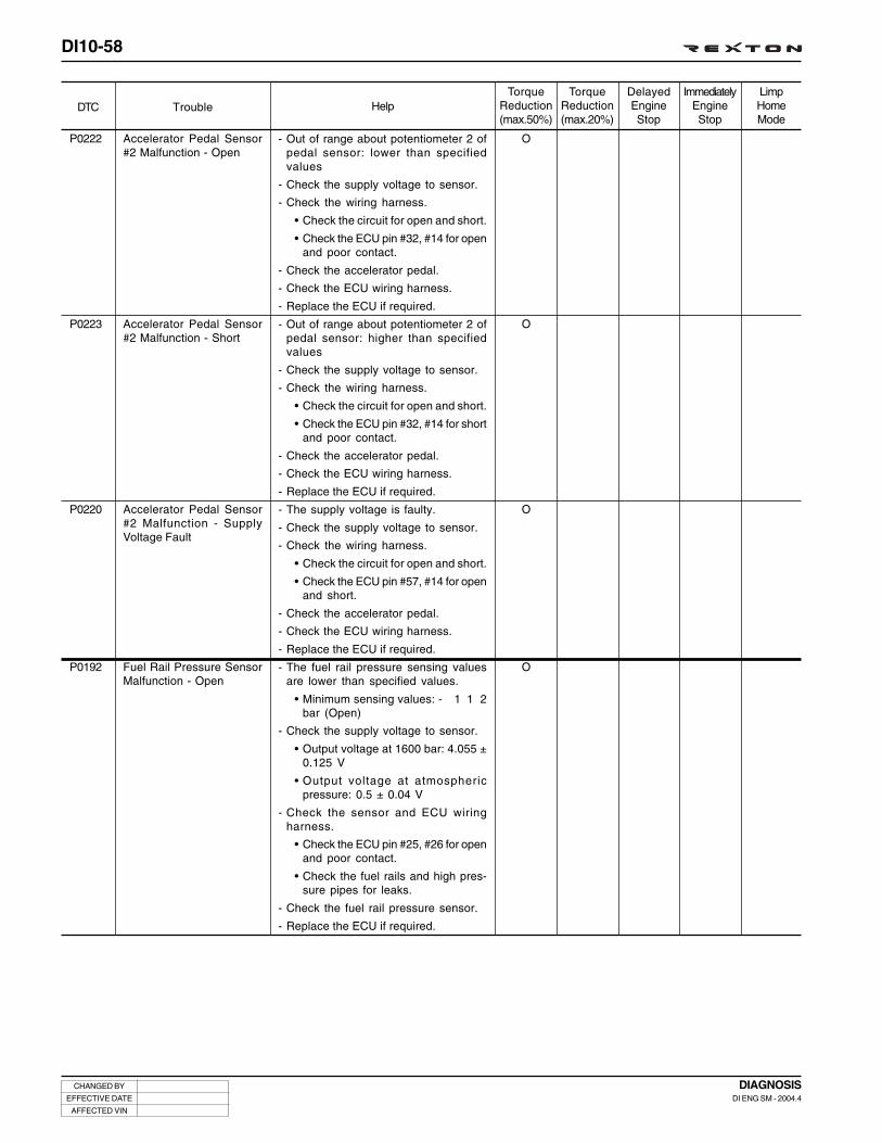
DI10-58
CHANGED BY
EFFECTIVE DATE
AFFECTED VIN
DIAGNOSISDI ENG SM - 2004.4
DTC TroubleLimpHomeMode
ImmediatelyEngineStop
DelayedEngineStop
TorqueReduction(max.20%)
HelpTorque
Reduction(max.50%)
P0222
P0223
P0220
P0192
Accelerator Pedal Sensor#2 Malfunction - Open
Accelerator Pedal Sensor#2 Malfunction - Short
Accelerator Pedal Sensor#2 Malfunction - SupplyVoltage Fault
Fuel Rail Pressure SensorMalfunction - Open
O
O
O
O
- Out of range about potentiometer 2 ofpedal sensor: lower than specifiedvalues
- Check the supply voltage to sensor.
- Check the wiring harness.
• Check the circuit for open and short.
• Check the ECU pin #32, #14 for openand poor contact.
- Check the accelerator pedal.
- Check the ECU wiring harness.
- Replace the ECU if required.
- Out of range about potentiometer 2 ofpedal sensor: higher than specifiedvalues
- Check the supply voltage to sensor.
- Check the wiring harness.
• Check the circuit for open and short.
• Check the ECU pin #32, #14 for shortand poor contact.
- Check the accelerator pedal.
- Check the ECU wiring harness.
- Replace the ECU if required.
- The supply voltage is faulty.
- Check the supply voltage to sensor.
- Check the wiring harness.
• Check the circuit for open and short.
• Check the ECU pin #57, #14 for openand short.
- Check the accelerator pedal.
- Check the ECU wiring harness.
- Replace the ECU if required.
- The fuel rail pressure sensing valuesare lower than specified values.
• Minimum sensing values: - 1 1 2bar (Open)
- Check the supply voltage to sensor.
• Output voltage at 1600 bar: 4.055 ±0.125 V
• Output voltage at atmosphericpressure: 0.5 ± 0.04 V
- Check the sensor and ECU wiringharness.
• Check the ECU pin #25, #26 for openand poor contact.
• Check the fuel rails and high pres-sure pipes for leaks.
- Check the fuel rail pressure sensor.
- Replace the ECU if required.

DI10-59
CHANGED BY
EFFECTIVE DATE
AFFECTED VIN
DIAGNOSISDI ENG SM - 2004.4
DTC TroubleLimpHomeMode
ImmediatelyEngineStop
DelayedEngineStop
TorqueReduction(max.20%)
HelpTorque
Reduction(max.50%)
P0193
P0190
P0191
Fuel Rail Pressure SensorMalfunction - Short
Supply Voltage Fault toFuel Rail Pressure Sensor
Fuel Rail Pressure SensorSignal Fault
O
O
O
- The fuel rail pressure sensing valuesare higher than specified values.
• Maximum sensing values: 1,600 bar(Short)
- Check the supply voltage to sensor.
• Output voltage at 1600 bar: 4.055±0.125V
• Output voltage at atmosphericpressure: 0.5±0.04V
- Check the sensor and ECU wiringharness.
• Check the ECU pin #25, #26 for shortand poor contact.
• Check the fuel rails and high pres-sure pipes for leaks.
- Check the fuel rail pressure sensor.
- Replace the ECU if required.
- The supply voltage to fuel rail pres-sure sensor is faulty.
- Check the supply voltage to sensor.
• Output voltage at 1600 bar: 4.055±0.125V
• Output voltage at atmosphericpressure: 0.5±0.04V
- Check the sensor and ECU wiringharness.
• Check the ECU pin #6, #26 for openand short.
• Check the fuel rails and high pres-sure pipes for leaks.
- Check the fuel rail pressure sensor.
- Replace the ECU if required.
- The rail pressure drop is too high.
- Check the supply voltage to sensor.
• Output voltage at 1600 bar: 4.055 ±0.125 V
• Output voltage at atmosphericpressure: 0.5 ± 0.04 V
- Check the sensor and ECU wiringharness.
• Check the ECU pin #6, #26 for openand short.
• Check the fuel rails and high pres-sure pipes for leaks.
- Check the fuel rail pressure sensor.
- Replace the ECU if required.

DI10-60
CHANGED BY
EFFECTIVE DATE
AFFECTED VIN
DIAGNOSISDI ENG SM - 2004.4
DTC TroubleLimpHomeMode
ImmediatelyEngineStop
DelayedEngineStop
TorqueReduction(max.20%)
HelpTorque
Reduction(max.50%)
P1192
P1193
P1190
Fuel Rail Pressure SensorInitial Signal Fault - Low
Fuel Rail Pressure SensorInitial Signal Fault - High
Fuel Rail Pressure SensorInitial Signal Fault
O
O
O
- The rail pressure sensor initial valuesare lower than specified values withthe ignition “ON”.
• Minimum sensing values: - 90 bar(Open)
- Check the supply voltage to sensor.
• Output voltage at 1600 bar: 4.055 ±0.125 V
• Output voltage at atmosphericpressure: 0.5 ± 0.04 V
- Check the sensor and ECU wiringharness.
• Check the ECU pin #25, #26 for openand poor contact.
• Check the fuel rails and high pres-sure pipes for leaks.
- Check the fuel rail pressure sensor.
- Replace the ECU if required.
- The rail pressure sensor initial valuesare higher than specified values withthe ignition “ON”.
• Maximum sensing values: 90 bar(Short)
- Check the supply voltage to sensor.
• Output voltage at 1600 bar: 4.055 ±0.125 V
• Output voltage at atmosphericpressure: 0.5 ± 0.04 V
- Check the sensor and ECU wiringharness.
• Check the ECU pin #25, #26 for shortand poor contact.
• Check the fuel rails and high pres-sure pipes for leaks.
- Check the fuel rail pressure sensor.
- Replace the ECU if required.
- The rail pressure sensor initial valuesare higher or lower than specified val-ues with the ignition “ON”.
• Maximum sensing values: 90 bar(Short)
• Minimum sensing values: - 90 bar(Open)
- Check the supply voltage to sensor.
• Output voltage at 1600 bar: 4.055 ±0.125 V
• Output voltage at atmosphericpressure: 0.5 ± 0.04 V
- Check the sensor and ECU wiringharness.
• Check the ECU pin #25, #26 for openand short.
• Check the fuel rails and high pres-sure pipes for leaks.
- Check the fuel rail pressure sensor.
- Replace the ECU if required.

DI10-61
CHANGED BY
EFFECTIVE DATE
AFFECTED VIN
DIAGNOSISDI ENG SM - 2004.4
DTC TroubleLimpHomeMode
ImmediatelyEngineStop
DelayedEngineStop
TorqueReduction(max.20%)
HelpTorque
Reduction(max.50%)
P0215
P1500
P0642
P0643
P0641
Main Relay Fault - Stuck
Vehicle Speed Fault
ECU Supply Voltage 1 Fault- Low (5 V)
ECU Supply Voltage 1 Fault- High (5 V)
ECU Supply Voltage 1 Fault(5 V)
- The main relay is stuck ; Shut down.
- Resistance of main relay: 92 Ω ± 9 Ω(at 20°C)
- Check the main relay wiring harness.
- Check the ECU wiring harness.
• Check the ECU pin #3, 4, 5 for openand short.
- If the forced operation is not available,replace the ECU.
- Check the fuse for main relay
- The vehicle speed signal through CANcommunication is faulty.
- Check the CAN communication line foropen and short.
- Check the ABS/ESP and TCU commu-nication lines.
- Check the ECU wiring harness.
- Replace the ECU if required.
- Malfunction reference supply voltagefrom ECU
• Supply voltage: 5 V
- Check the supply voltage to each sen-sor
• Supply voltage (5 V): acceleratorpedal sensor 1, HFM sensor, railpressure sensor, booster pressuresensor, cam sensor
- Check the wiring harnesses.
- Replace the ECU if required.
- Malfunction reference supply voltagefrom ECU
• Supply voltage: 5 V
- Check the supply voltage to each sen-sor
• Supply voltage (5 V): acceleratorpedal sensor 1, HFM sensor, railpressure sensor, booster pressuresensor, cam sensor
- Check the wiring harnesses.
- Replace the ECU if required.
- Malfunction reference supply voltagefrom ECU
• Supply voltage: 5 V
- Check the supply voltage to each sen-sor
• Supply voltage (5 V): acceleratorpedal sensor 1, HFM sensor, railpressure sensor, booster pressuresensor, cam sensor
- Check the wiring harnesses.
- Replace the ECU if required.

DI10-62
CHANGED BY
EFFECTIVE DATE
AFFECTED VIN
DIAGNOSISDI ENG SM - 2004.4
DTC TroubleLimpHomeMode
ImmediatelyEngineStop
DelayedEngineStop
TorqueReduction(max.20%)
HelpTorque
Reduction(max.50%)
P0652
P0653
P0651
P0698
P0699
ECU Supply Voltage 2 Fault- Low (5 V)
ECU Supply Voltage 2 Fault- High (5 V)
ECU Supply Voltage 2 Fault(5 V)
ECU Supply Voltage Fault -Low (2.5 V)
ECU Supply Voltage Fault -High (2.5 V)
O
O
O
- Malfunction reference supply voltagefrom ECU
• Supply voltage: 5 V
- Check the supply voltage to each sen-sor
• Supply voltage (5 V): acceleratorpedal sensor 1, HFM sensor, railpressure sensor, booster pressuresensor, cam sensor
- Check the wiring harnesses.
- Replace the ECU if required.
- Malfunction reference supply voltagefrom ECU
• Supply voltage: 5 V
- Check the supply voltage to each sen-sor
• Supply voltage (5 V): acceleratorpedal sensor 1, HFM sensor, railpressure sensor, booster pressuresensor, cam sensor
- Check the wiring harnesses.
- Replace the ECU if required.
- Malfunction reference supply voltagefrom ECU
• Supply voltage: 5 V
- Check the supply voltage to each sen-sor
• Supply voltage (5 V): acceleratorpedal sensor 1, HFM sensor, railpressure sensor, booster pressuresensor, cam sensor
- Check the wiring harnesses.
- Replace the ECU if required.
- Malfunction reference supply voltagefrom ECU
• Supply voltage: 2.5 V
- Check the supply voltage to each sen-sor
• Supply voltage (2.5 V): acceleratorpedal sensor 2
- Check the wiring harnesses.
- Replace the ECU if required.
- Malfunction reference supply voltagefrom ECU
• Supply voltage: 2.5 V
- Check the supply voltage to each sen-sor
• Supply voltage (2.55 V): accelera-tor pedal sensor 2
- Check the wiring harnesses.
- Replace the ECU if required.
O
O
O

DI10-63
CHANGED BY
EFFECTIVE DATE
AFFECTED VIN
DIAGNOSISDI ENG SM - 2004.4
DTC TroubleLimpHomeMode
ImmediatelyEngineStop
DelayedEngineStop
TorqueReduction(max.20%)
HelpTorque
Reduction(max.50%)
P0697
P0245
P0246
P0606
P1607
P1600
P1601
P1602
ECU Supply Voltage Fault(2.5 V)
Turbo Charger ActuatorCircuit Fault - Short
Turbo Charger ActuatorCircuit Fault - Short to B+
ECU Watchdog Fault
ECU Injector Cut Fault
ECU Shut Down Fault
ECU Fault
ECU Fault
O
O
- Malfunction reference supply voltagefrom ECU
• Supply voltage: 2.5 V
- Check the supply voltage to each sen-sor
• Supply voltage (2.55 V): accelera-tor pedal sensor 2
- Check the wiring harnesses.
- Replace the ECU if required.
- The waste gate driver circuit is shortto ground or open
- Check the actuator wiring harness.
- Check the solenoid valve.
- Check the ECU wiring harness.
• Check the ECU pin #95 for open andshort.
- Replace the ECU if required.
- The turbo charger actuator powersource circuit is short.
- Check the actuator wiring harness.
- Check the solenoid valve.
- Check the ECU wiring harness for shortand poor contact.
- Replace the ECU if required.
- The ECU is defective.
- Check the chassis ground wiringharness.
- Check the ECU.
- Replace the ECU if required.
- The ECU is defective.
- Check the chassis ground wiringharness.
- Check the ECU.
- Replace the ECU if required.
- The ECU is defective.
- Check the chassis ground wiringharness.
- Check the ECU.
- Replace the ECU if required.
- The ECU is defective.
- Check the chassis ground wiringharness.
- Check the ECU.
- Replace the ECU if required.
- The ECU is defective.
- Check the chassis ground wiringharness.
- Check the ECU.
- Replace the ECU if required.

DI10-64
CHANGED BY
EFFECTIVE DATE
AFFECTED VIN
DIAGNOSISDI ENG SM - 2004.4
DTC TroubleLimpHomeMode
ImmediatelyEngineStop
DelayedEngineStop
TorqueReduction(max.20%)
HelpTorque
Reduction(max.50%)
P1614
P1615
P1616
P1606
P1620
P1621
P1622
P1603
P1604
P1605
P1148
ECU C2I/MDP Fault
ECU Fault
ECU Fault
ECU Fault
ECU Fault
ECU Fault
ECU Fault
ECU Fault
ECU Fault
ECU Fault
Accelerometer (KnockSensor) Learning Fault
O
O
O
O
- The ECU is defective.
- Check the chassis ground wiringharness.
- Check the ECU.
- Replace the ECU if required.
- The ECU is defective.
- Check the chassis ground wiringharness.
- Check the ECU.
- Replace the ECU if required.
- The ECU is defective.
- Check the chassis ground wiringharness.
- Check the ECU.
- Replace the ECU if required.
- The ECU is defective.
- Check the chassis ground wiringharness.
- Check the ECU.
- Replace the ECU if required.
- The ECU is defective.
- Check the chassis ground wiringharness.
- Check the ECU.
- Replace the ECU if required.
- The ECU is defective.
- Check the chassis ground wiringharness.
- Check the ECU.
- Replace the ECU if required.
- The ECU is defective.
- Check the chassis ground wiringharness.
- Check the ECU.
- Replace the ECU if required.
- The ECU is defective.
- Check the chassis ground wiringharness.
- Check the ECU.
- Replace the ECU if required.
- The ECU is defective.
- Check the chassis ground wiringharness.
- Check the ECU.
- Replace the ECU if required.
- The ECU is defective.
- Check the chassis ground wiringharness.
- Check the ECU.
- Replace the ECU if required.
- Check if the MDP is successful.
- Check the accelerometer (knocksensor) sensor and wiring harness.
- Replace the ECU if required.
O
O
O
O
O
O
O

DI10-65
CHANGED BY
EFFECTIVE DATE
AFFECTED VIN
DIAGNOSISDI ENG SM - 2004.4
DTC TroubleLimpHomeMode
ImmediatelyEngineStop
DelayedEngineStop
TorqueReduction(max.20%)
HelpTorque
Reduction(max.50%)
P0400
P1235
P1608
P0335
P1170
P1676
P1677
EGR Control Valve Fault
VGT Operation Fault
ECU Fault
No Crank Signals
Torque Trim Fault - High
Glow Plug CommunicationFault
Glow Plug Controller Fault
O
- When the EGR emission is more thanspecified value.
• The EGR controller circuit is openor short to ground.
• The EGR controller is short tobattery.
- Check the EGR actuator wiring harness.
- Check the supply voltage to EGR sole-noid valve.
- Check if the EGR valve is stuck.
- Check the resistance of EGR valve: 15.4 Ω.
- Check the ECU wiring harness.
• Check the ECU pin #96 for open andshort.
- The boost pressure control is faulty.
- Check the air intake system.
- Check the supply voltage to sensor.
- Check the wiring harness and the ECUwiring harness.
- Replace the ECU if required.
- The ECU is defective.
- Check the chassis ground wiringharness.
- Check the ECU.
- Replace the ECU if required.
- Refer to P0372.
- Refer to P0372.
- The communication between ECU andglow plug is faulty.
- Check the communication line betweenECU and glow plug.
- Check the glow plug wiring harness.
- Check the resistance of glow plug:below 1 Ω.
- Check the glow plug relay.
- Check the ECU wiring harness.
• Check the ECU pin #113 for short toground.
- Replace the ECU if required.
- The communication between ECU andglow plug is faulty.
- Check the communication line betweenECU and glow plug.
- Check the glow plug wiring harness.
- Check the resistance of glow plug:below 1Ω.
- Check the glow plug relay.
- Check the ECU wiring harness.
• Check the ECU pin #113 for short toground.
- Replace the ECU if required.

DI10-66
CHANGED BY
EFFECTIVE DATE
AFFECTED VIN
DIAGNOSISDI ENG SM - 2004.4
DTC TroubleLimpHomeMode
ImmediatelyEngineStop
DelayedEngineStop
TorqueReduction(max.20%)
HelpTorque
Reduction(max.50%)
P0671
P0672
P0673
P0674
P0675
P1671
#1 Glow Plug Fault - Open
#2 Glow Plug Fault - Open
#3 Glow Plug Fault - Open
#4 Glow Plug Fault - Open
#5 Glow Plug Fault - Open
#1 Glow Plug Fault - Short(B+)
- The glow plug circuit is open.
- Check the communication line betweenECU and each glow plug.
- Check each glow plug wiring harness.
- Check the resistance of each glowplug: below 1 Ω.
- Check each glow plug relay.
- Check the ECU wiring harness.
- Replace the ECU if required.
- The glow plug circuit is open.
- Check the communication line betweenECU and each glow plug.
- Check each glow plug wiring harness.
- Check the resistance of each glowplug: below 1 Ω.
- Check each glow plug relay.
- Check the ECU wiring harness.
- Replace the ECU if required.
- The glow plug circuit is open.
- Check the communication line betweenECU and each glow plug.
- Check each glow plug wiring harness.
- Check the resistance of each glowplug: below 1 Ω.
- Check each glow plug relay.
- Check the ECU wiring harness.
- Replace the ECU if required.
- The glow plug circuit is open.
- Check the communication line betweenECU and each glow plug.
- Check each glow plug wiring harness.
- Check the resistance of each glowplug: below 1Ω.
- Check each glow plug relay.
- Check the ECU wiring harness.
- Replace the ECU if required.
- The glow plug circuit is open.
- Check the communication line betweenECU and each glow plug.
- Check each glow plug wiring harness.
- Check the resistance of each glowplug: below 1 Ω.
- Check each glow plug relay.
- Check the ECU wiring harness.
- Replace the ECU if required.
- The glow plug circuit is short.
- Check the communication line betweenECU and each glow plug.
- Check each glow plug wiring harness.
- Check the resistance of each glowplug: below 1 Ω.
- Check each glow plug relay.
- Check the ECU wiring harness.
- Replace the ECU if required.

DI10-67
CHANGED BY
EFFECTIVE DATE
AFFECTED VIN
DIAGNOSISDI ENG SM - 2004.4
DTC TroubleLimpHomeMode
ImmediatelyEngineStop
DelayedEngineStop
TorqueReduction(max.20%)
HelpTorque
Reduction(max.50%)
P1672
P1673
P1674
P1675
P0700
P1540
P1541
P1542
#2 Glow Plug Fault - Short(B+)
#3 Glow Plug Fault - Short(B+)
#4 Glow Plug Fault - Short(B+)
#5 Glow Plug Fault - Short(B+)
TCU Signal Fault
Air Conditioner OperatingCircuit Fault - Open
Air Conditioner OperatingCircuit Fault - Short
Air Conditioner OperatingCircuit Fault - Short toGround
- The glow plug circuit is short.
- Check the communication line betweenECU and each glow plug.
- Check each glow plug wiring harness.
- Check the resistance of each glowplug: below 1 Ω
- Check each glow plug relay.
- Check the ECU wiring harness.
- Replace the ECU if required.
- The glow plug circuit is short.
- Check the communication line betweenECU and each glow plug.
- Check each glow plug wiring harness.
- Check the resistance of each glowplug: below 1 Ω
- Check each glow plug relay.
- Check the ECU wiring harness.
- Replace the ECU if required.
- The glow plug circuit is short.
- Check the communication line betweenECU and each glow plug.
- Check each glow plug wiring harness.
- Check the resistance of each glowplug: below 1 Ω
- Check each glow plug relay.
- Check the ECU wiring harness.
- Replace the ECU if required.
- The glow plug circuit is short.
- Check the communication line betweenECU and each glow plug.
- Check each glow plug wiring harness.
- Check the resistance of each glowplug: below 1Ω
- Check each glow plug relay.
- Check the ECU wiring harness.
- Replace the ECU if required.
- The communication between ECU andTCU is faulty.
- Check the communication line betweenECU and TCU.
- Check the ECU pin #54, 73 for openand short.
- Replace the ECU if required.
- Check the air conditioner sensors andwiring harnesses.
- Check the ECU wiring harness.
- Check the ECU if required.
- Check the air conditioner sensors andwiring harnesses.
- Check the ECU wiring harness.
- Check the ECU if required.
- Check the air conditioner sensors andwiring harnesses.
- Check the ECU wiring harness.
- Check the ECU if required.

DI10-68
CHANGED BY
EFFECTIVE DATE
AFFECTED VIN
DIAGNOSISDI ENG SM - 2004.4
DTC TroubleLimpHomeMode
ImmediatelyEngineStop
DelayedEngineStop
TorqueReduction(max.20%)
HelpTorque
Reduction(max.50%)
P1149
P1634
P1635
P1630
P1631
P1632
Too High Water Level inFuel Filter
Immobilizer Fault (refer toimmobilizer section)
No response from Immobi-lizer (refer to immobilizersection)
Wrong response from Im-mobilizer (refer to immobi-lizer section)
Immobilizer Fault (refer toimmobilizer section)
Immobilizer Fault (refer toimmobilizer section)
- Drain the water from fuel filter.
- No response from immobilizer.
- Perform the immobilizer coding again.
- Check the ECU wiring harness.
• Check the ECU pin #34 for open andshort.
- Check the immobilizer unit for open andshort or check the supply voltage.
- Check the immobilizer antenna.
- Replace the ECU if required.
- No response from immobilizer.
- Perform the immobilizer coding again.
- Check the ECU wiring harness.
• Check the ECU pin #34 for open andshort.
- Check the immobilizer unit for open andshort or check the supply voltage.
- Check the immobilizer antenna.
- Replace the ECU if required.
- The invalid key is inserted or no communi-cation between transponder and immobi-lizer (no response from transponder).
- Perform the immobilizer coding again.
- Check the ECU wiring harness.
• Check the ECU pin #34 for open andshort.
- Check the immobilizer unit for open andshort or check the supply voltage.
- Check the immobilizer antenna andtransponder for damage.
- Replace the ECU if required.
- The immobilizer is not operating.
- Perform the immobilizer coding again.
- Check the ECU wiring harness.
• Check the ECU pin #34 for open andshort.
- Check the immobilizer unit for open andshort or check the supply voltage.
- Check the immobilizer antenna andtransponder for damage.
- Replace the ECU if required.
- No response from immobilizer.
- Perform the immobilizer coding again.
- Check the ECU wiring harness.
• Check the ECU pin #34 for open andshort.
- Check the immobilizer unit for open andshort or check the supply voltage.
- Check the immobilizer antenna andtransponder for damage.
- Replace the ECU if required.

DI10-69
CHANGED BY
EFFECTIVE DATE
AFFECTED VIN
DIAGNOSISDI ENG SM - 2004.4
DTC TroubleLimpHomeMode
ImmediatelyEngineStop
DelayedEngineStop
TorqueReduction(max.20%)
HelpTorque
Reduction(max.50%)
P1633
P0633
P1636
Immobilizer Fault (refer toimmobilizer section)
Immobilizer Fault (refer toimmobilizer section)
Immobilizer Fault (refer toimmobilizer section)
- No key coding.
- Perform the immobilizer coding again.
- Check the ECU wiring harness.
• Check the ECU pin #34 for open andshort.
- Check the immobilizer unit for open andshort or check the supply voltage.
- Check the immobilizer antenna andtransponder for damage.
- Replace the ECU if required.
- Key memory is not available (permissible- 5).
- Perform the immobilizer coding again.
- Check the ECU wiring harness.
• Check the ECU pin #34 for open andshort.
- Check the immobilizer unit for open andshort or check the supply voltage.
- Check the immobilizer antenna andtransponder for damage.
- Replace the ECU if required.
- Severe trouble is not defined.
- Perform the immobilizer coding again.
- Check the ECU wiring harness.
• Check the ECU pin #34 for open andshort.
- Check the immobilizer unit for open andshort or check the supply voltage.
- Check the immobilizer antenna andtransponder for damage.
- Replace the ECU if required.

MEMO
.............................................................................................................................................................................................................................................................................................................................................................................................................................................................................
.............................................................................................................................................................................................................................................................................................................................................................................................................................................................................
.............................................................................................................................................................................................................................................................................................................................................................................................................................................................................
.............................................................................................................................................................................................................................................................................................................................................................................................................................................................................
.............................................................................................................................................................................................................................................................................................................................................................................................................................................................................
.............................................................................................................................................................................................................................................................................................................................................................................................................................................................................
.............................................................................................................................................................................................................................................................................................................................................................................................................................................................................
.............................................................................................................................................................................................................................................................................................................................................................................................................................................................................
.............................................................................................................................................................................................................................................................................................................................................................................................................................................................................
.............................................................................................................................................................................................................................................................................................................................................................................................................................................................................
.............................................................................................................................................................................................................................................................................................................................................................................................................................................................................
.............................................................................................................................................................................................................................................................................................................................................................................................................................................................................
.............................................................................................................................................................................................................................................................................................................................................................................................................................................................................
.............................................................................................................................................................................................................................................................................................................................................................................................................................................................................
.............................................................................................................................................................................................................................................................................................................................................................................................................................................................................
.............................................................................................................................................................................................................................................................................................................................................................................................................................................................................
.............................................................................................................................................................................................................................................................................................................................................................................................................................................................................
.............................................................................................................................................................................................................................................................................................................................................................................................................................................................................
.............................................................................................................................................................................................................................................................................................................................................................................................................................................................................
.............................................................................................................................................................................................................................................................................................................................................................................................................................................................................
.............................................................................................................................................................................................................................................................................................................................................................................................................................................................................
.............................................................................................................................................................................................................................................................................................................................................................................................................................................................................
.............................................................................................................................................................................................................................................................................................................................................................................................................................................................................
.............................................................................................................................................................................................................................................................................................................................................................................................................................................................................
.............................................................................................................................................................................................................................................................................................................................................................................................................................................................................
.............................................................................................................................................................................................................................................................................................................................................................................................................................................................................
.............................................................................................................................................................................................................................................................................................................................................................................................................................................................................
.............................................................................................................................................................................................................................................................................................................................................................................................................................................................................
.............................................................................................................................................................................................................................................................................................................................................................................................................................................................................

DI10-71
CHANGED BY
EFFECTIVE DATE
AFFECTED VIN
DIAGNOSISDI ENG SM - 2004.4
INDEX OF DTCHMF sensor Signal Fault (Electric Failure) .......... DI10-75
P0102 ............................................................ DI10-75P0103 ............................................................ DI10-75P0100 ............................................................ DI10-75
Cam Position Sensor (missing event) .................. DI10-76P0344 ............................................................ DI10-76
Cam Position Sensor Malfunction(Poor Synchronization of Crank and Cam) ........... DI10-77
P0341 ............................................................ DI10-77
Too Small Clearance of Crank Angle Sensor ........ DI10-78P0219 ............................................................ DI10-78
Too Large Clearance of Crank Angle Sensor ........ DI10-79P0336 ............................................................ DI10-79
Crank Angle Sensor Malfunction .......................... DI10-80P0372 ............................................................ DI10-80
Barometric Sensor Malfunction (Out of range, usingstrategy of restoring by MAP sensor) .................. DI10-81
P1107 ............................................................ DI10-81P1108 ............................................................ DI10-81P1105 ............................................................ DI10-81
Battery Voltage Monitoring Signal Malfunction ..... DI10-82P0562 ............................................................ DI10-82P0563 ............................................................ DI10-82P0560 ............................................................ DI10-82
Booster Pressure Sensor Malfunction(Out of range with Key ON) ................................. DI10-84
P0109 ............................................................ DI10-84P0106 ............................................................ DI10-84
Booster Pressure Sensor Malfunction(Out of range with Key ON) ................................. DI10-86
P0107 ............................................................ DI10-86P0108 ............................................................ DI10-86P0105 ............................................................ DI10-86P1106 ............................................................ DI10-86
Booster Pressure Malfunction(Implausible Signal) ............................................. DI10-88
P1109 ............................................................ DI10-88
Brake Pedal Switch Malfunction .......................... DI10-90P0571 ............................................................ DI10-90
Brake Lamp Signal Fault ..................................... DI10-91P1572 ............................................................ DI10-91P1571 ............................................................ DI10-91
High Wiring Resistance (Injector #1) ................... DI10-92P1286 ............................................................ DI10-92P1287 ............................................................ DI10-92
High Wiring Resistance (Injector #2) ................... DI10-93P1288 ............................................................ DI10-93P1289 ............................................................ DI10-93
High Wiring Resistance (Injector #3) ................... DI10-94P1292 ............................................................ DI10-94P1293 ............................................................ DI10-94
High Wiring Resistance (Injector #4) ................... DI10-95P1294 ............................................................ DI10-95P1295 ............................................................ DI10-95
High Wiring Resistance (Injector #5) ................... DI10-96P1290 ............................................................ DI10-96P1291 ............................................................ DI10-96
Clutch Switch Malfunction ................................... DI10-97P0704 ............................................................ DI10-97
Coolant Temperature Sensor Malfunction(Implausible Signal) ............................................. DI10-98
P1115 ............................................................. DI10-98
Coolant Temperature Sensor Malfunction(Electric Fault) .................................................... DI10-99
P0117 ............................................................ DI10-99P0118 ............................................................ DI10-99P0115 ............................................................ DI10-99
Too Fast or Low Main Relay Operation .............. DI10-100P0685 .......................................................... DI10-100
EGR Actuator Malfunction ................................. DI10-101P1405 .......................................................... DI10-101P1406 .......................................................... DI10-101
Condenser Fan Driving Signal Fault (Type 1) ..... DI10-102P1480 .......................................................... DI10-102P1481 .......................................................... DI10-102P1482 .......................................................... DI10-102

DI10-72
CHANGED BY
EFFECTIVE DATE
AFFECTED VIN
DIAGNOSISDI ENG SM - 2004.4
Condenser Fan Driving Signal Fault (Type 2) ..... DI10-103P1526 .......................................................... DI10-103P1527 .......................................................... DI10-103P1528 .......................................................... DI10-103
#1 Accelerometer Malfunction(Idling Signal/Too Small Noise Ratio) ................. DI10-104
P0325 .......................................................... DI10-104
#2 Accelerometer Malfunction(Idling Signal/Too Small Noise Ratio) ................. DI10-105
P0330 .......................................................... DI10-105
Injector Bank 1 Malfunction(Short to Ground or B+) ..................................... DI10-106
P1611 .......................................................... DI10-106P1612 .......................................................... DI10-106
Injector Bank 2 Malfunction(Short to Ground or B+) ..................................... DI10-108
P1618 .......................................................... DI10-108P1619 .......................................................... DI10-108
Cylinder Balancing Fault (Injector #1) =Clogged Air Intake System ................................ DI10-110
P0263 .......................................................... DI10-110
Cylinder Balancing Fault (Injector #2) =Clogged Air Intake System .................................DI10-111
P0266 ...........................................................DI10-111
Cylinder Balancing Fault (Injector #4) =Clogged Air Intake System ................................ DI10-112
P0272 .......................................................... DI10-112
Cylinder Balancing Fault (Injector #5) =Clogged Air Intake System ................................ DI10-113
P0275 .......................................................... DI10-113
Cylinder Balancing Fault (Injector #3) =Clogged Air Intake System ................................ DI10-114
P0269 .......................................................... DI10-114
Open Circuit (Injector #1) ................................... DI10-115P0201 .......................................................... DI10-115
Open Circuit (Injector #2) ................................... DI10-116P0202 .......................................................... DI10-116
Open Circuit (Injector #4) ................................... DI10-117P0204 .......................................................... DI10-117
Open Circuit (Injector #5) ................................... DI10-118P0205 .......................................................... DI10-118
Open Circuit (Injector #3) ................................... DI10-119P0203 .......................................................... DI10-119
HSD Circuit Short to LSE (Injector #1) .............. DI10-120P1201 .......................................................... DI10-120
HSD Circuit Short to LSE (Injector #2) .............. DI10-121P1202 .......................................................... DI10-121
HSD Circuit Short to LSE (Injector #4) .............. DI10-122P1204 .......................................................... DI10-122
HSD Circuit Short to LSE (Injector #5) .............. DI10-123P1205 .......................................................... DI10-123
HSD Circuit Short to LSE (Injector #3) .............. DI10-124P1203 .......................................................... DI10-124
Fuel Temperature Sensor Malfunction ................ DI10-125P0182 .......................................................... DI10-125P0183 .......................................................... DI10-125P0180 .......................................................... DI10-125
Glow Plug Malfunction (Driving Signal) .............. DI10-126P1678 .......................................................... DI10-126P1679 .......................................................... DI10-126
Heater 1 Malfunction (Driving Signal) ................. DI10-127P1530 .......................................................... DI10-127P1531 .......................................................... DI10-127P1532 .......................................................... DI10-127
Heater 2 Malfunction (Driving Signal) ................. DI10-128P1534 .......................................................... DI10-128P1535 .......................................................... DI10-128P1536 .......................................................... DI10-128
Rail Pressure Control Fault(Too High Pressure) ........................................... DI10-129
P1254 .......................................................... DI10-129P1253 .......................................................... DI10-129
Rail Pressure Control Fault(Too High IMV Current Trim, drift) ....................... DI10-131
P1256 .......................................................... DI10-131P1257 .......................................................... DI10-131P1258 .......................................................... DI10-131P1259 .......................................................... DI10-131
Rail Pressure Control Fault(Too Slow Pressure Build Up while Cranking) .... DI10-133
P1191 .......................................................... DI10-133

DI10-73
CHANGED BY
EFFECTIVE DATE
AFFECTED VIN
DIAGNOSISDI ENG SM - 2004.4
IMV Operation Fault (Electrical Fault) ................ DI10-135P0255 .......................................................... DI10-135P0251 .......................................................... DI10-135P0253 .......................................................... DI10-135
Intake Air Temperature Sensor Fault(Electric Fault) .................................................. DI10-136
P0112 .......................................................... DI10-136P0113 .......................................................... DI10-136P0110 .......................................................... DI10-136
MDP Fault (Injector #1) ..................................... DI10-137P1171 .......................................................... DI10-137
MDP Fault (Injector #2) ..................................... DI10-137P1172 .......................................................... DI10-137
MDP Fault (Injector #4) ..................................... DI10-138P1174 .......................................................... DI10-138
MDP Fault (Injector #5) ..................................... DI10-138P1175 .......................................................... DI10-138
MDP Fault (Injector #3) ..................................... DI10-139P1173 .......................................................... DI10-139
Rail Pressure Fault (Too High) ........................... DI10-140P1252 .......................................................... DI10-140
Accelerator Pedal Sensor Malfunction(Relationship between Track 1 and Track 2) ...... DI10-142
P1120 .......................................................... DI10-142P1121 .......................................................... DI10-142
Accelerator Pedal Sensor Malfunction (Limp Home Mode Operation) ........................... DI10-143
P1122 .......................................................... DI10-143
Accelerator Pedal Sensor Malfunction(Torque Reduction Mode Operation) .................. DI10-144
P1123 .......................................................... DI10-144
Accelerator Pedal Sensor Malfunction (Electrical Fault, Pedal Stuck) ......................... DI10-145
P1124 .......................................................... DI10-145
Accelerator Pedal Sensor Malfunction(Electrical Fault, Track 1) .................................. DI10-146
P0122 .......................................................... DI10-146P0123 .......................................................... DI10-146P0120 .......................................................... DI10-146
Accelerator Pedal Sensor Malfunction(Electrical Fault, Track 2) .................................. DI10-147
P0222 .......................................................... DI10-147P0223 .......................................................... DI10-147P0220 .......................................................... DI10-147
Fuel Rail Pressure Sensor Malfunction(Out of Range, ADC or Vref) .............................. DI10-148
P0192 .......................................................... DI10-148P0193 .......................................................... DI10-148P0190 .......................................................... DI10-148P0191 .......................................................... DI10-148
Fuel Rail Pressure Sensor Malfunction(Out of Range when Key ON) ............................ DI10-150
P1192 .......................................................... DI10-150P1193 .......................................................... DI10-150P1190 .......................................................... DI10-150
Main Relay Malfunction - Stuck ......................... DI10-152P0215 .......................................................... DI10-152
Vehicle Speed Fault .......................................... DI10-153P1500 .......................................................... DI10-153
5V Supply Voltage 1 Fault ................................. DI10-154P0642 .......................................................... DI10-154P0643 .......................................................... DI10-154P0641 .......................................................... DI10-154
5V Supply Voltage 2 Fault ................................. DI10-155P0652 .......................................................... DI10-155P0653 .......................................................... DI10-155P0651 .......................................................... DI10-155
2.5V Supply Voltage Fault ................................. DI10-156P0698 .......................................................... DI10-156P0699 .......................................................... DI10-156P0697 .......................................................... DI10-156
Turbo Charger Actuator Operation Fault (signal) DI10-157P0245 .......................................................... DI10-157P0246 .......................................................... DI10-157
ECU Watchdog Fault ........................................ DI10-158P0606 .......................................................... DI10-158
ECU Watchdog Fault (Injector Cut-off) ............... DI10-159P1607 .......................................................... DI10-159
ECU Watchdog Fault (Watchdog Trip) .............. DI10-160P1600 .......................................................... DI10-160P1601 .......................................................... DI10-160P1602 .......................................................... DI10-160

DI10-74
CHANGED BY
EFFECTIVE DATE
AFFECTED VIN
DIAGNOSISDI ENG SM - 2004.4
ECU Non-Volatile Memory Fault ........................ DI10-161P1614 .......................................................... DI10-161P1615 .......................................................... DI10-161P1616 .......................................................... DI10-161P1606 .......................................................... DI10-161P1620 .......................................................... DI10-161P1621 .......................................................... DI10-161P1622 .......................................................... DI10-161
ECU Memory Integration Fault .......................... DI10-162P1603 .......................................................... DI10-162P1604 .......................................................... DI10-162P1605 .......................................................... DI10-162
Accelerometer Learning Fault ............................ DI10-163P1148 .......................................................... DI10-163
EGR Valve Control Fault .................................... DI10-164P0400 .......................................................... DI10-164
VGT Operation Fault ......................................... DI10-165P1235 .......................................................... DI10-165
TBD .................................................................. DI10-167P1608 .......................................................... DI10-167
No Crank Signal ................................................ DI10-168P0335 .......................................................... DI10-168
High Torque Trim ............................................... DI10-169P1170 .......................................................... DI10-169
Glow Plug Module Communication Fault ........... DI10-170P1676 .......................................................... DI10-170P1677 .......................................................... DI10-170
Glow Plug Module Circuit Malfunction - Open .... DI10-171P0674 .......................................................... DI10-171P0675 .......................................................... DI10-171P0671 .......................................................... DI10-171P0672 .......................................................... DI10-171P0673 .......................................................... DI10-171
Glow Plug Module Circuit Malfunction - Short .... DI10-172P1674 .......................................................... DI10-172P1675 .......................................................... DI10-172P1671 .......................................................... DI10-172P1672 .......................................................... DI10-172P1673 .......................................................... DI10-172
TCU Signal Fault ............................................... DI10-173P0700 .......................................................... DI10-173
Air Conditioner Operating Circuit Fault .............. DI10-174P1540 .......................................................... DI10-174P1541 .......................................................... DI10-174P1542 .......................................................... DI10-174
Excessive Water in Fuel Filter ........................... DI10-175P1149 .......................................................... DI10-175
Immobilizer Malfunction ..................................... DI10-176P1634 .......................................................... DI10-176
P4335 .......................................................... DI10-176
P1630 .......................................................... DI10-176
P1631 .......................................................... DI10-176
P1632 .......................................................... DI10-176
P1633 .......................................................... DI10-176
P0633 .......................................................... DI10-176
P1636 .......................................................... DI10-176

DI10-75
CHANGED BY
EFFECTIVE DATE
AFFECTED VIN
DIAGNOSISDI ENG SM - 2004.4
Trouble Code and Symptom
Diagnosis Procedures
TROUBLE DIAGNOSIS PROCEDURES
HMF sensor Signal Fault (Electric Failure)
Low Signal
High Signal
Supply Voltage
Trouble Code Symptom
P0102
P0103
P0100
MIL ON
Not available EGR control(Air flow)
YES
YES
YES
YES
Read DTC
Fault in sensor supply voltage?
Check sensor wiring
NO
Wiring Problem?
Check sensor resistance
NO
Check ECU wiring
Wiring Problem?
Check wiring and insulation
NO
Wiring Problem?
Replace ECU
NO
Repair orreplace
Sensor problem caused by supply voltage.Locate the problem while disconnecting thesensor connector one by one. If not a sen-sor problem, check the sensor supply volt-age circuit for open and short.
Repair orreplace
Repair wiring
NO
YESResistance Problem? Replace
sensor

DI10-76
CHANGED BY
EFFECTIVE DATE
AFFECTED VIN
DIAGNOSISDI ENG SM - 2004.4
Trouble Code and Symptom
Diagnosis Procedures
Cam Position Sensor (missing event)
Cam Position Sensor Malfunction
Trouble Code Symptom
P0344
YES
YES
YES
YES
YES
Check sensor wiring
Wiring Problem?
Check sensor
NO
Sensor Problem?
Check ECU wiring
NO
Wiring Problem?
Check wiring insulation
Wiring Problem?
Check cam installation
NO
Cam Wheel Problem?
NO
Replace ECU
Repair orreplace
Replacesensor
Repair orreplace
Repair wiring
Replace camwheel
NO
NO
Check if the cam andflywheel signals are normal
with an oscilloscope
Anmormal Signal?YES
Repair orreplace

DI10-77
CHANGED BY
EFFECTIVE DATE
AFFECTED VIN
DIAGNOSISDI ENG SM - 2004.4
Trouble Code and Symptom
Diagnosis Procedures
Cam Position Sensor Malfunction - Poor Synchro-
nization
Trouble Code Symptom
P0341 MIL ON
YES
YES
YES
YES
YES
Check sensor wiring
Wiring Problem?
Check sensor
NO
Sensor Problem?
Check ECU wiring
NO
Wiring Problem?
Check wiring insulation
Wiring Problem?
Check cam installation
NO
Cam Wheel Problem?
NO
Replace ECU
Repair orreplace
Replacesensor
Repair orreplace
Repair wiring
Replace camwheel
NO
NO
Check if the cam andflywheel signals are normal
with an oscilloscope
Anmormal Signal?YES
Repair wiring
Cam Position Sensor Malfunction(Poor Synchronization of Crank and Cam)

DI10-78
CHANGED BY
EFFECTIVE DATE
AFFECTED VIN
DIAGNOSISDI ENG SM - 2004.4
Trouble Code and Symptom
Diagnosis Procedures
Too Small Clearance of Crank AngleSensor
Too Small Clearance of Crank Angle Sensor
Trouble Code Symptom
P0219
YES
YES
YES
YES
Check sensor wiring
Wiring Problem?
Check ECU wiring
NO
Wiring Problem?
Check insulation and opencircuit
NO
Wiring Problem?
Trouble Continues?
Replace wheel
NO
Trouble Continues?
NO
Repair completed
Repair orreplace
Repair orreplace
Replace APSwheel
Replace ECU
Trouble Continues?
New sensor installed
YESRepair wiring
YESReplace VR
sensor
NO
NO

DI10-79
CHANGED BY
EFFECTIVE DATE
AFFECTED VIN
DIAGNOSISDI ENG SM - 2004.4
Trouble Code and Symptom
Diagnosis Procedures
Too Large Clearance of Crank AngleSensor
Too Large Clearance of Crank Angle Sensor
Trouble Code Symptom
P0336 MIL ON
YES
YES
YES
YES
Check sensor wiring
Wiring Problem?
Check ECU wiring
NO
Wiring Problem?
Check insulation and opencircuit
NO
Wiring Problem?
Trouble Continues?
Replace wheel
NO
Trouble Continues?
NO
Repair completed
Repair orreplace
Repair orreplace
Replace APSwheel
Replace ECU
Trouble Continues?
New sensor installed
YESRepair wiring
YESReplace VR
sensor
NO
NO

DI10-80
CHANGED BY
EFFECTIVE DATE
AFFECTED VIN
DIAGNOSISDI ENG SM - 2004.4
Trouble Code and Symptom
Diagnosis Procedures
Crank Angle Sensor Malfunction
Crank Angle Sensor Malfunction 3
Trouble Code Symptom
P0372 MIL ON
YES
YES
YES
YES
Check sensor wiring
Wiring Problem?
Check ECU wiring
NO
Wiring Problem?
Check insulation and opencircuit
NO
Wiring Problem?
Trouble Continues?
Replace wheel
NO
Trouble Continues?
NO
Repair completed
Repair orreplace
Repair orreplace
Replace APSwheel
Replace ECU
Trouble Continues?
New sensor installed
YESRepair wiring
YESReplace VR
sensor
NO
NO

DI10-81
CHANGED BY
EFFECTIVE DATE
AFFECTED VIN
DIAGNOSISDI ENG SM - 2004.4
Trouble Code and Symptom
Diagnosis Procedures
Barometric Sensor Malfunction(Out of range, using strategy ofrestoring by MAP sensor)
Low Signal
High Signal
Supply Voltage
Trouble Code Symptom
P1107
P1108
P1105
Replace ECU

DI10-82
CHANGED BY
EFFECTIVE DATE
AFFECTED VIN
DIAGNOSISDI ENG SM - 2004.4
Not operatable.
Injector #1 resistance fault. Use estimate resis-
tance level.
Injector #2 resistance fault. Use estimate resis-
tance level.
Injector #4 resistance fault. Use estimate resis-
tance level.
Injector #5 resistance fault. Use estimate resis-
tance level.
Injector #3 resistance fault. Use estimate resis-
tance level.
Unable EGR control (Air Flow)
Unable RPC trim problem detection
Unable HP leak detection
Unable accelerometer learing strategy
MIL ON
Operating limited rail pressure mode
TBD
Trouble Code and Symptom
Battery Voltage Monitoring SignalMalfunction
Low Signal
High Signal
Supply Voltage
Trouble Code Symptom
P0562
P0563
P0560
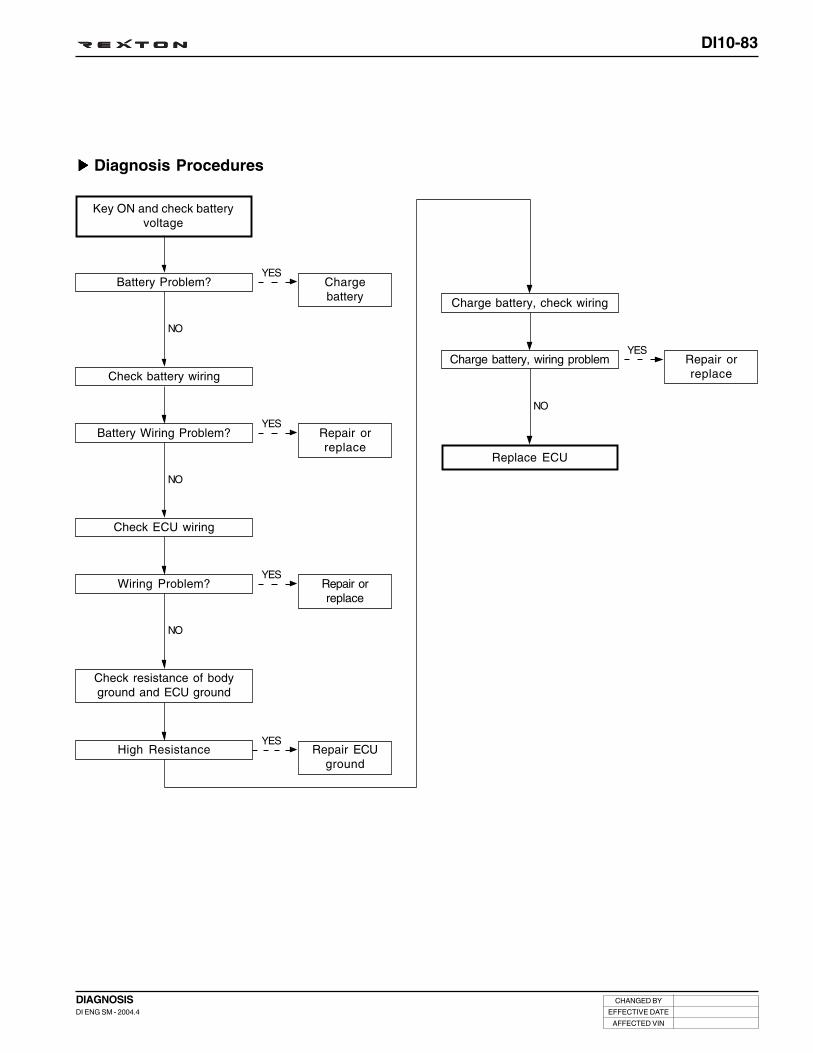
DI10-83
CHANGED BY
EFFECTIVE DATE
AFFECTED VIN
DIAGNOSISDI ENG SM - 2004.4
Diagnosis Procedures
YES
YES
YES
YES
Key ON and check batteryvoltage
Battery Problem?
Check battery wiring
NO
Battery Wiring Problem?
Check ECU wiring
NO
Wiring Problem?
Charge battery, check wiring
Charge battery, wiring problem
NO
Replace ECU
Chargebattery
Repair orreplace
Repair orreplace
Repair orreplace
NO
Check resistance of bodyground and ECU ground
High ResistanceYES
Repair ECUground

DI10-84
CHANGED BY
EFFECTIVE DATE
AFFECTED VIN
DIAGNOSISDI ENG SM - 2004.4
Trouble Code and Symptom
Diagnosis Procedures1. Diagnosis Procedures (Boost Pressure)
Booster Pressure Sensor Malfunction(Out of range with Key ON)
Low
High
Trouble Code Symptom
P0109
P0106 Location demand=change the boost control to
O.L. mode at f (boost demand, engine cycling speed)
YES
Read DTC
Booster Pressure Problem?
Check air line malfunction:* VGT/Turbo. * Air filter.
* Vacuum line. * Vacuum pump.* Solenoid valve open.
* Vane condition.* Air inlet valve function
NO
Repiar Completed
Refer to Diagnosis Tree “Check sensor(1)”

DI10-85
CHANGED BY
EFFECTIVE DATE
AFFECTED VIN
DIAGNOSISDI ENG SM - 2004.4
2. Diagnosis Procedure (Check sensor (1))
YES
YES
YES
YES
Read DTC
Fault in sensor supply voltage?
Check sensor wiring
NO
Wiring Problem?
Visually check sensor
NO
Check ECU wiring
Wiring Problem?
Check wiring and insulation
NO
Wiring Problem?
Repiar Completed
NO
Repair orreplace
Sensor problem caused by supply voltage.Locate the problem while disconnecting thesensor connector one by one. If not a sen-sor problem, check the sensor supply volt-age circuit for open and short.
Repair orreplace
Repair wiring
NO
YESSensor Problem? Replace
sensor
YES
Replace sensor
Trouble Continues?
NO
Replace ECU
NO

DI10-86
CHANGED BY
EFFECTIVE DATE
AFFECTED VIN
DIAGNOSISDI ENG SM - 2004.4
Trouble Code and Symptom
Diagnosis Procedures1. Diagnosis Procedures (Boost Pressure)
Booster Pressure Sensor Malfunction(Out of range with Key ON)
Low
High
Supply Voltage
GRAD
Trouble Code Symptom
P0107
P0108
P0105
P1106
Location demand=change the boost control to
O.L. mode at f (boost demand, engine cycling speed)
YES
Read DTC
Booster Pressure Problem?
Check air line malfunction:* VGT/Turbo. * Air filter.
* Vacuum line. * Vacuum pump.* Solenoid valve open.
* Vane condition.* Air inlet valve function
NO
Repiar Completed
Refer to Diagnosis Tree “Check sensor(1)”

DI10-87
CHANGED BY
EFFECTIVE DATE
AFFECTED VIN
DIAGNOSISDI ENG SM - 2004.4
2. Diagnosis Procedures (check sensor (1))
YES
YES
YES
YES
Read DTC
Fault in sensor supply voltage?
Check sensor wiring
NO
Wiring Problem?
Visually check sensor
NO
Check ECU wiring
Wiring Problem?
Check wiring and insulation
NO
Wiring Problem?
Repiar Completed
NO
Repair orreplace
Sensor problem caused by supply voltage.Locate the problem while disconnecting thesensor connector one by one. If not a sen-sor problem, check the sensor supply volt-age circuit for open and short.
Repair orreplace
Repair wiring
NO
YESSensor Problem? Replace
sensor
YES
Replace sensor
Trouble Continues?
NO
Replace ECU
NO

DI10-88
CHANGED BY
EFFECTIVE DATE
AFFECTED VIN
DIAGNOSISDI ENG SM - 2004.4
Trouble Code and Symptom
Diagnosis Procedures1. Diagnosis Procedures (Boost Pressure)
Booster Pressure Malfunction(Implausible Signal)
Booster Pressure Sensor Malfunction
Trouble Code Symptom
P1109
Location demand=change the boost control to
O.L. mode at f (boost demand, engine cycling speed)
YES
Read DTC
Booster Pressure SensorProblem?
Check air line malfunction:* VGT/Turbo. * Air filter.
* Vacuum line. * Vacuum pump.* Solenoid valve open.
* Vane condition.* Air inlet valve function
NO
Repiar Completed
Refer to Diagnosis Tree “Check sensor(1)”

DI10-89
CHANGED BY
EFFECTIVE DATE
AFFECTED VIN
DIAGNOSISDI ENG SM - 2004.4
2. Diagnosis Procedures (check sensor (1))
YES
YES
YES
YES
Read DTC
Fault in sensor supply voltage?
Check sensor wiring
NO
Wiring Problem?
Visually check sensor
NO
Check ECU wiring
Wiring Problem?
Check wiring and insulation
NO
Wiring Problem?
Repiar Completed
NO
Repair orreplace
Sensor problem caused by supply voltage.Locate the problem while disconnecting thesensor connector one by one. If not a sen-sor problem, check the sensor supply volt-age circuit for open and short.
Repair orreplace
Repair wiring
NO
YESSensor Problem? Replace
sensor
YES
Replace sensor
Trouble Continues?
NO
Replace ECU
NO

DI10-90
CHANGED BY
EFFECTIVE DATE
AFFECTED VIN
DIAGNOSISDI ENG SM - 2004.4
Trouble Code and Symptom
Diagnosis Procedures
Brake Pedal Switch Malfunction
Brake Pedal Switch Malfunction
Trouble Code Symptom
P0571 MIL ON
Unable Cruise Control
YES
YES
YES
YES
YES
Check switch wiring
Wiring Problem?
Check 12V switch supplyvoltage
NO
Source Power Problem?
Check switch operation
NO
Switch Problem?
Check ECU wiring
Wiring Problem?
Check wiring and insulation
NO
Wiring Problem?
NO
Replace ECU
Repair orreplace
Check wiringand fuse
Replaceswitch
Repair orreplace
Repair wiring
NO

DI10-91
CHANGED BY
EFFECTIVE DATE
AFFECTED VIN
DIAGNOSISDI ENG SM - 2004.4
Trouble Code and Symptom
Diagnosis Procedures
Brake Lamp Signal Fault
Brake Lamp Signal Fault
Brake Lamp Signal Fault
Trouble Code Symptom
P1572
P1571
MIL ON
MIL ON
YES
YES
YES
YES
YES
Check switch wiring
Wiring Problem?
Check 12V switch supplyvoltage
NO
Source Power Problem?
Check switch operation
NO
Switch Problem?
Check ECU wiring
Wiring Problem?
Check wiring and insulation
NO
Wiring Problem?
NO
Replace ECU
Repair orreplace
Check wiringand fuse
Replaceswitch
Repair orreplace
Repair wiring
NO

DI10-92
CHANGED BY
EFFECTIVE DATE
AFFECTED VIN
DIAGNOSISDI ENG SM - 2004.4
Trouble Code and Symptom
Diagnosis Procedures
High Wiring Resistance (Injector #1)
Low
High
Trouble Code Symptom
P1286
P1287
Resistance of injector #1 fault. Use estimate re-
sistance level.
MIL ON
Unable Dynamic Leak of Injector #1
Unable Accelerometer Learning Strategy
YES
YES
Read DTC
“Low” Fault?
Read DTC
NO
“High” Fault?
NO
No any other possibility
Refer toinjector circuitmalfunction(open) tree
Refer toinjector circuitmalfunction(short) tree

DI10-93
CHANGED BY
EFFECTIVE DATE
AFFECTED VIN
DIAGNOSISDI ENG SM - 2004.4
Trouble Code and Symptom
Diagnosis Procedures
High Wiring Resistance (Injector #2)
Low
High
Trouble Code Symptom
P1288
P1289
Resistance of injector #2 fault. Use estimate re-
sistance level.
MIL ON
Unable Dynamic Leak of Injector #2
Unable Accelerometer Learning Strategy
YES
YES
Read DTC
“Low” Fault?
Read DTC
NO
“High”s Fault?
NO
No any other possibility
Refer toinjector circuitmalfunction(open) tree
Refer toinjector circuitmalfunction(short) tree

DI10-94
CHANGED BY
EFFECTIVE DATE
AFFECTED VIN
DIAGNOSISDI ENG SM - 2004.4
Trouble Code and Symptom
Diagnosis Procedures
High Wiring Resistance (Injector #3)
Low
High
Trouble Code Symptom
P1292
P1293
Resistance of injector #4 fault. Use estimate re-
sistance level.
MIL ON
Unable Dynamic Leak of Injector #4
Unable Accelerometer Learning Strategy
YES
YES
Read DTC
“Low” Fault?
Read DTC
NO
“High” Fault?
NO
No any other possibility
Refer toinjector circuitmalfunction(open) tree
Refer toinjector circuitmalfunction(short) tree

DI10-95
CHANGED BY
EFFECTIVE DATE
AFFECTED VIN
DIAGNOSISDI ENG SM - 2004.4
Trouble Code and Symptom
Diagnosis Procedures
High Wiring Resistance (Injector #4)
Low
High
Trouble Code Symptom
P1294
P1295
Resistance of injector #5 fault. Use estimate re-
sistance level.
MIL ON
Unable Dynamic Leak of Injector #5
Unable Accelerometer Learning Strategy
YES
YES
Read DTC
“Low” Fault?
Read DTC
NO
“High” Fault?
NO
No any other possibility
Refer toinjector circuitmalfunction(open) tree
Refer toinjector circuitmalfunction(short) tree

DI10-96
CHANGED BY
EFFECTIVE DATE
AFFECTED VIN
DIAGNOSISDI ENG SM - 2004.4
Trouble Code and Symptom
Diagnosis Procedures
High Wiring Resistance (Injector #5)
Low
High
Trouble Code Symptom
P1290
P1291
Resistance of injector #3 fault. Use estimate re-
sistance level.
MIL ON
Unable Dynamic Leak of Injector #3
Unable Accelerometer Learning Strategy
YES
YES
Read DTC
“Low” Fault?
Read DTC
NO
“High” Fault?
NO
No any other possibility
Refer toinjector circuitmalfunction(open) tree
Refer toinjector circuitmalfunction(short) tree

DI10-97
CHANGED BY
EFFECTIVE DATE
AFFECTED VIN
DIAGNOSISDI ENG SM - 2004.4
Trouble Code and Symptom
Diagnosis Procedures
Clutch Switch Malfunction
Clutch Switch Malfunction
Trouble Code Symptom
P0704
YES
YES
YES
YES
YES
Check switch wiring
Wiring Problem?
Check 12V switch supplyvoltage
NO
Source Power Problem?
Check switch operation
NO
Switch Contact Problem?
Check ECU wiring
Wiring Problem?
Check wiring and insulation
NO
Wiring Problem?
NO
Replace ECU
Repair orreplace
Check wiringand fuse
Replace switch
Repair orreplace
Repair wiring
NO

DI10-98
CHANGED BY
EFFECTIVE DATE
AFFECTED VIN
DIAGNOSISDI ENG SM - 2004.4
Trouble Code and Symptom
Diagnosis Procedures
Coolant Temperature Sensor Malfunction(Implausible Signal)
Coolant Temperature Sensor Malfunction
Trouble Code Symptom
P1115 Unable Air Conditioner Operation
Below Limited Temperature of Engine Overheat
Detection
YES
YES
YES
YES
Read DTC
Fault in sensor supply voltage?
Check sensor wiring
NO
Wiring Problem?
Check sensor resistance
NO
Check ECU wiring
Wiring Problem?
Check wiring and insulation
NO
Wiring Problem?
Replace ECU
NO
Repair orreplace
Sensor problem caused by supply voltage.Locate the problem while disconnecting thesensor connector one by one. If not a sen-sor problem, check the sensor supply volt-age circuit for open and short.
Repair orreplace
Repair wiring
NO
YESResistance Problem? Replace
sensor
NO

DI10-99
CHANGED BY
EFFECTIVE DATE
AFFECTED VIN
DIAGNOSISDI ENG SM - 2004.4
Trouble Code and Symptom
Diagnosis Procedures
Coolant Temperature Sensor Malfunction(Electric Fault)
Low
High
Supply Voltage
Trouble Code Symptom
P0117
P0118
P0115
Unable Air Conditioner Operation
Below Limited Temperature of Engine Overheat
Detection
YES
YES
YES
YES
Read DTC
Fault in sensor supply voltage?
Check sensor wiring
NO
Wiring Problem?
Check sensor resistance
NO
Check ECU wiring
Wiring Problem?
Check wiring and insulation
Wiring Problem?
Replace ECU
NO
Repair orreplace
Sensor problem caused by supply voltage.Locate the problem while disconnecting thesensor connector one by one. If not a sen-sor problem, check the sensor supply volt-age circuit for open and short.
Repair orreplace
Repair wiring
NO
YESResistance Problem? Replace
sensor
NO

DI10-100
CHANGED BY
EFFECTIVE DATE
AFFECTED VIN
DIAGNOSISDI ENG SM - 2004.4
Trouble Code and Symptom
Diagnosis Procedures
Too Fast or Low Main Relay Operation
Main Relay Malfunction
Trouble Code Symptom
P0685
YES
YES
YES
YES
Check relay wiring
Wiring Problem?
Check ECU wiring
NO
Wiring Problem?
Check wiring and insulation
NO
Wiring Problem?
Perform forced operationand replace relay
Not available forced operation?
NO
Repiar Completed
Repair orreplace
Repair orreplace
Repair wiring
Replace ECU
NO

DI10-101
CHANGED BY
EFFECTIVE DATE
AFFECTED VIN
DIAGNOSISDI ENG SM - 2004.4
Trouble Code and Symptom
Diagnosis Procedures
EGR Actuator Malfunction
EGR Vacuum Modulator - Short to GND
EGR Vacuum Modulator - Short to +Batt
Trouble Code Symptom
P1405
P1406
MIL ON
Unable EGR Control (Air Flow)
YES
YES
YES
YES
Check actuator wiring
Wiring Problem?
Check resistance of actuator
NO
Resistance Problem?
Check ECU wiring
NO
Wiring Problem?
Replace actuator
Trouble Continues?
NO
Repiar Completed
Repair orreplace
Replaceactuator
Repair orreplace
Replace ECU
NO
YES
Check wiring and insulation
NO
Wiring Problem?
NO
Repair wiring

DI10-102
CHANGED BY
EFFECTIVE DATE
AFFECTED VIN
DIAGNOSISDI ENG SM - 2004.4
Trouble Code and Symptom
Diagnosis Procedures
Condenser Fan Driving Signal Fault(Type 1)
Open Circuit
Short Circuit
Short to Ground
Trouble Code Symptom
P1480
P1481
P1482
Unable Air Conditioner Operation
MIL ON
Below Limited Temperature of Engine Overheat
Detection
YES
YES
YES
Check relay wiring
Wiring Problem?
Check ECU wiring
NO
Wiring Problem?
Check wiring and insulation
NO
Wiring Problem?
Repiar Completed
Repair orreplace
Repair orreplace
Repair wiring
NO
YES
Perform forced operationand replace relay
NO
Not available forced operation?
NO
Replace ECU

DI10-103
CHANGED BY
EFFECTIVE DATE
AFFECTED VIN
DIAGNOSISDI ENG SM - 2004.4
Trouble Code and Symptom
Diagnosis Procedures
Condenser Fan Driving Signal Fault(Type 2)
Open Circuit
Short Circuit
Short to Ground
Trouble Code Symptom
P1526
P1527
P1528
Unable Air Conditioner Operation
MIL ON
Below Limited Temperature of Engine Overheat
Detection
YES
YES
YES
Check relay wiring
Wiring Problem?
Check ECU wiring
NO
Wiring Problem?
Check wiring and insulation
NO
Wiring Problem?
Repiar Completed
Repair orreplace
Repair orreplace
Repair wiring
NO
YES
Perform forced drive andreplace relay
NO
Not available forced operation?
NO
Replace ECU

DI10-104
CHANGED BY
EFFECTIVE DATE
AFFECTED VIN
DIAGNOSISDI ENG SM - 2004.4
Trouble Code and Symptom
Diagnosis Procedures
#1 Accelerometer Malfunction(Idling Signal/Too Small Noise Ratio)
#1 Accelerometer (Knock Sensor) Malfunction
Trouble Code Symptom
P0325 MIL ON
Unable Accelerometer Learning Strategy
YES
YES
YES
YES
“Caution: Check the sensingvalue of coolant temp., intakeair temp., fuel temp. baromet-ric pressure. Incorrect defaultvalues of theses sensors maycause wrong diagnosis.”
Check accelerometer wiringand tightening torque, espe-cially shield ground.
Wiring Problem?
Check ECU wiring
NO
Wiring Problem?
Check wiring and insulation
NO
Wiring Problem?
Replace accelerometer(knock sensor)
Trouble Continues?
NO
Repiar Completed
Repair orreplace
Repair orreplace
Repair wiring
Replace ECU
NO
NO
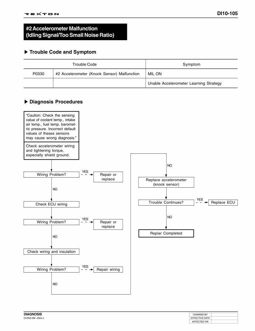
DI10-105
CHANGED BY
EFFECTIVE DATE
AFFECTED VIN
DIAGNOSISDI ENG SM - 2004.4
Trouble Code and Symptom
Diagnosis Procedures
#2 Accelerometer Malfunction(Idling Signal/Too Small Noise Ratio)
#2 Accelerometer (Knock Sensor) Malfunction
Trouble Code Symptom
P0330 MIL ON
Unable Accelerometer Learning Strategy
YES
YES
YES
YES
“Caution: Check the sensingvalue of coolant temp., intakeair temp., fuel temp. baromet-ric pressure. Incorrect defaultvalues of theses sensorsmay cause wrong diagnosis.”
Check accelerometer wiringand tightening torque,especially shield ground.
Wiring Problem?
Check ECU wiring
NO
Wiring Problem?
Check wiring and insulation
NO
Wiring Problem?
Replace accelerometer(knock sensor)
Trouble Continues?
NO
Repiar Completed
Repair orreplace
Repair orreplace
Repair wiring
Replace ECU
NO
NO

DI10-106
CHANGED BY
EFFECTIVE DATE
AFFECTED VIN
DIAGNOSISDI ENG SM - 2004.4
Resistance of injector #1 fault. Use estimate re-
sistance level.
Resistance of injector #4 fault. Use estimate re-
sistance level.
Resistance of injector #3 fault. Use estimate re-
sistance level.
MIL ON
Unable Dynamic Leak of Injector #1
Unable Dynamic Leak of Injector #4
Unable Dynamic Leak of Injector #3
Unable Cylinder Balancing
Unable Injector #1 Operation
Unable Injector #4 Operation
Unable Injector #3 Operation
Unable High Pressure Leak Detection
Unable Accelerometer Learning Strategy
Trouble Code and Symptom
Injector Bank 1 Malfunction(Short to Ground or B+)
Low Injector Bank 1 Voltage
High Injector Bank 1 Voltage
Trouble Code Symptom
P1611
P1612

DI10-107
CHANGED BY
EFFECTIVE DATE
AFFECTED VIN
DIAGNOSISDI ENG SM - 2004.4
Diagnosis Procedures1. Fuel Injection Bank 1/2
YES
YES
YES
Injector - short (SC+ or SC-)
Key OFF and check injectorwiring
Injector Wiring Problem?
Disconnect injector connec-tor and key ON
NO
Trouble Continues?
Delete default and key OFF.Key ON while connecting
injector connectors one by one.
NO
Trouble Recurred?
Repair orreplace
Refer to checkinjector wiring
Replace theinjector - Enternew injectorC2I into ECUNO
Repeat same procedures forall injectors
2. Check Injector Wiring
YES
YES
Check ECU wiring
Wiring Problem?
Check wiring and insulation
NO
Wiring Problem?
NO
Repair orreplace
Repair wiring
Replace ECU

DI10-108
CHANGED BY
EFFECTIVE DATE
AFFECTED VIN
DIAGNOSISDI ENG SM - 2004.4
Resistance of injector #2 fault. Use estimate re-
sistance level.
Resistance of injector #5 fault. Use estimate re-
sistance level.
MIL ON
Unable Dynamic Leak of Injector #2
Unable Dynamic Leak of Injector #5
Unable Cylinder Balancing
Unable Injector #2 Operation
Unable Injector #5 Operation
Unable High Pressure Leak Detection
Unable Accelerometer Learning Strategy
Trouble Code and Symptom
Injector Bank 2 Malfunction(Short to Ground or B+)
Low Injector Bank 2 Voltage
High Injector Bank 2 Voltage
Trouble Code Symptom
P1618
P1619

DI10-109
CHANGED BY
EFFECTIVE DATE
AFFECTED VIN
DIAGNOSISDI ENG SM - 2004.4
Diagnosis Procedures1. Fuel Injection Bank 1/2
YES
YES
YES
Injector - short
Key OFF and check injectorwiring
Injector Wiring Problem?
Disconnect injector connec-tor and key ON
NO
Trouble Continues?
Delete default and key OFF.Key ON while connecting
injector connectors one by one.
NO
Trouble Recurred?
Repair orreplace
Refer to checkinjector wiring
Replace theinjector - Enternew injectorC2I into ECUNO
Repeat same procedures forall injectors
2. Check Injector Wiring
YES
YES
Check ECU wiring
Wiring Problem?
Check wiring and insulation
NO
Wiring Problem?
NO
Repair orreplace
Repair wiring
Replace ECU

DI10-110
CHANGED BY
EFFECTIVE DATE
AFFECTED VIN
DIAGNOSISDI ENG SM - 2004.4
Trouble Code and Symptom
Diagnosis Procedures
Cylinder Balancing Fault (Injector #1) =Clogged Air Intake System
#1 Cylinder Balancing Fault
Trouble Code Symptom
P0263 MIL ON
Unable Accelerometer Learning Strategy
YES
YES
YES
YES
Read DTC
Injector Circuit Open?
Check engine hardware
NO
Engine Hardware Problem?
Check glow plug
NO
Glow Plug Problem?
Check air intake system
Air Intake System Clogged?
NO
Replace injector and enter newinjector C2I value into ECU
Circuit Open:Wiring problem
Repair orreplace
Repair orreplace
Repair airintake system
and checkEGR
NO
YES
Perform forced valve opera-tion and check it
NO
Valve Problem?
NO
Repair orreplace valve

DI10-111
CHANGED BY
EFFECTIVE DATE
AFFECTED VIN
DIAGNOSISDI ENG SM - 2004.4
Trouble Code and Symptom
Diagnosis Procedures
Cylinder Balancing Fault (Injector #2) =Clogged Air Intake System
#2 Cylinder Balancing Fault
Trouble Code Symptom
P0266 MIL ON
Unable Accelerometer Learning Strategy
YES
YES
YES
YES
Read DTC
Injector Circuit Open?
Check engine hardware
NO
Engine Hardware Problem?
Check glow plug
NO
Glow Plug Problem?
Check air intake system
Air Intake System Clogged?
NO
Replace injector and enternew injector C2I into ECU
Circuit Open:Wiring problem
Repair orreplace
Repair orreplace
Repair airintake system
and checkEGR
NO
YES
Perform forced valve opera-tion and check it
NO
Valve Problem?
NO
Repair orreplace valve

DI10-112
CHANGED BY
EFFECTIVE DATE
AFFECTED VIN
DIAGNOSISDI ENG SM - 2004.4
Trouble Code and Symptom
Diagnosis Procedures
Cylinder Balancing Fault (Injector #4) =Clogged Air Intake System
#4 Cylinder Balancing Fault
Trouble Code Symptom
P0272 MIL ON
Unable Accelerometer Learning Strategy
YES
YES
YES
YES
Read DTC
Injector Circuit Open?
Check engine hardware
NO
Engine Hardware Problem?
Check glow plug
NO
Glow Plug Problem?
Check air intake system
Air Intake System Clogged?
NO
Replace injector and enter newinjector C2I value into ECU
Circuit Open:Wiring problem
Repair orreplace
Repair orreplace
Repair airintake system
and checkEGR
NO
YES
Perform forced valve opera-tion and check it
NO
Valve Problem?
NO
Repair orreplace valve

DI10-113
CHANGED BY
EFFECTIVE DATE
AFFECTED VIN
DIAGNOSISDI ENG SM - 2004.4
Trouble Code and Symptom
Diagnosis Procedures
Cylinder Balancing Fault (Injector #5) =Clogged Air Intake System
#5 Cylinder Balancing Fault
Trouble Code Symptom
P0275 MIL ON
Unable Accelerometer Learning Strategy
YES
YES
YES
YES
Read DTC
Injector Circuit Open?
Check engine hardware
NO
Engine Hardware Problem?
Check glow plug
NO
Glow Plug Problem?
Check air intake system
Air Intake System Clogged?
NO
Replace injector and enter newinjector C2I value into ECU
Circuit Open:Wiring problem
Repair orreplace
Repair orreplace
Repair airintake system
and checkEGR
NO
YES
Perform forced valve opera-tion and check it
NO
Valve Problem?
NO
Repair orreplace valve

DI10-114
CHANGED BY
EFFECTIVE DATE
AFFECTED VIN
DIAGNOSISDI ENG SM - 2004.4
Trouble Code and Symptom
Diagnosis Procedures
Cylinder Balancing Fault (Injector #3) =Clogged Air Intake System
#3 Cylinder Balancing Fault
Trouble Code Symptom
P0269 MIL ON
Unable Accelerometer Learning Strategy
YES
YES
YES
YES
Read DTC
Injector Circuit Open?
Check engine hardware
NO
Engine Hardware Problem?
Check glow plug
NO
Glow Plug Problem?
Check air intake system
Air Intake System Clogged?
NO
Replace injector and enter newinjector C2I value into ECU
Circuit Open:Wiring problem
Repair orreplace
Repair orreplace
Repair airintake system
and checkEGR
NO
YES
Perform forced valve opera-tion and check it
NO
Valve Problem?
NO
Repair orreplace valve

DI10-115
CHANGED BY
EFFECTIVE DATE
AFFECTED VIN
DIAGNOSISDI ENG SM - 2004.4
Trouble Code and Symptom
Diagnosis Procedures
Open Circuit (Injector #1)
#1 Injector Circuit - Open
Trouble Code Symptom
P0201 Unable RPC Trim Fault Detection
Unable H/P Leak Detection
Unable Accelerometer Learning Strategy
YES
YES
YES
Key OFF and check injectorwiring
Wiring Problem?
Check wiring insulation
NO
Wiring Problem?
NO
Check ECU wiring
Wiring Problem?
NO
Replace ECU
Repair orreplace
Repair orreplace
Repair orreplace
NO
YES
“If the wiring is normal,disconnect the injector
connectors and check theresistance (difficult to check
injector resistance)”
Injector Wiring Problem?
NO
Replaceinjector
and enter newinjector C2I
value into ECU

DI10-116
CHANGED BY
EFFECTIVE DATE
AFFECTED VIN
DIAGNOSISDI ENG SM - 2004.4
Trouble Code and Symptom
Diagnosis Procedures
Open Circuit (Injector #2)
#2 Injector Circuit - Open
Trouble Code Symptom
P0202 Unable RPC Trim Fault Detection
Unable H/P Leak Detection
Unable Accelerometer Learning Strategy
YES
YES
YES
Key OFF and check injectorwiring
Wiring Problem?
Check wiring insulation
NO
Wiring Problem?
NO
Check ECU wiring
Wiring Problem?
NO
Replace ECU
Repair orreplace
Repair orreplace
Repair orreplace
NO
YES
“If the wiring is normal,disconnect the injector
connectors and check theresistance (difficult to check
injector resistance)”
Injector Wiring Problem?
NO
Replaceinjector
and enter newinjector C2I
value into ECU
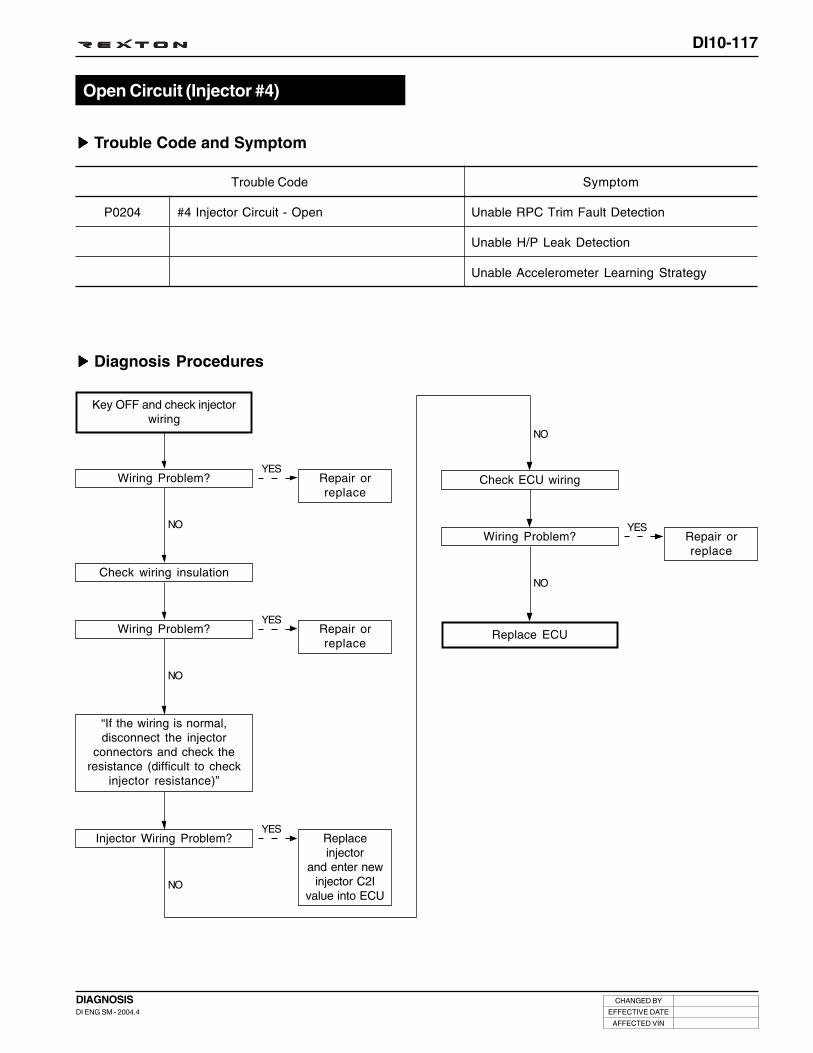
DI10-117
CHANGED BY
EFFECTIVE DATE
AFFECTED VIN
DIAGNOSISDI ENG SM - 2004.4
Trouble Code and Symptom
Diagnosis Procedures
Open Circuit (Injector #4)
#4 Injector Circuit - Open
Trouble Code Symptom
P0204 Unable RPC Trim Fault Detection
Unable H/P Leak Detection
Unable Accelerometer Learning Strategy
YES
YES
YES
Key OFF and check injectorwiring
Wiring Problem?
Check wiring insulation
NO
Wiring Problem?
NO
Check ECU wiring
Wiring Problem?
NO
Replace ECU
Repair orreplace
Repair orreplace
Repair orreplace
NO
YES
“If the wiring is normal,disconnect the injector
connectors and check theresistance (difficult to check
injector resistance)”
Injector Wiring Problem?
NO
Replaceinjector
and enter newinjector C2I
value into ECU

DI10-118
CHANGED BY
EFFECTIVE DATE
AFFECTED VIN
DIAGNOSISDI ENG SM - 2004.4
Trouble Code and Symptom
Diagnosis Procedures
Open Circuit (Injector #5)
#5 Injector Circuit - Open
Trouble Code Symptom
P0205 Unable RPC Trim Fault Detection
Unable H/P Leak Detection
Unable Accelerometer Learning Strategy
YES
YES
YES
Key OFF and check injectorwiring
Wiring Problem?
Check wiring insulation
NO
Wiring Problem?
NO
Check ECU wiring
Wiring Problem?
NO
Replace ECU
Repair orreplace
Repair orreplace
Repair orreplace
NO
YES
“If the wiring is normal,disconnect the injector
connectors and check theresistance (difficult to check
injector resistance)”
Injector Wiring Problem?
NO
Replaceinjector
and enter newinjector C2I
value into ECU

DI10-119
CHANGED BY
EFFECTIVE DATE
AFFECTED VIN
DIAGNOSISDI ENG SM - 2004.4
Trouble Code and Symptom
Diagnosis Procedures
Open Circuit (Injector #3)
#3 Injector Circuit - Open
Trouble Code Symptom
P0203 Unable RPC Trim Fault Detection
Unable H/P Leak Detection
Unable Accelerometer Learning Strategy
YES
YES
YES
Key OFF and check injectorwiring
Wiring Problem?
Check wiring insulation
NO
Wiring Problem?
NO
Check ECU wiring
Wiring Problem?
NO
Replace ECU
Repair orreplace
Repair orreplace
Repair orreplace
NO
YES
“If the wiring is normal,disconnect the injector
connectors and check theresistance (difficult to check
injector resistance)”
Injector Wiring Problem?
NO
Replaceinjector
and enter newinjector C2I
value into ECU

DI10-120
CHANGED BY
EFFECTIVE DATE
AFFECTED VIN
DIAGNOSISDI ENG SM - 2004.4
Trouble Code and Symptom
Diagnosis Procedures
HSD Circuit Short to LSE (Injector #1)
#1 Injector Circuit - Short
Trouble Code Symptom
P1201 Unable RPC Trim Fault Detection
Unable H/P Leak Detection
Unable Accelerometer Learning Strategy
YES
YES
YES
Key OFF and check injectorwiring
Wiring Problem?
Disconnect injector connector
NO
Same Trouble Continues?
NO
Check wiring insulation
Wiring Problem?
NO
Replace ECU
Repair orreplace
Replaceinjector
and enter newinjector C2I
value into ECU
Repair wiring
NO
YES
Shorted injector circuit.Check wiring from injector tip
to ECU.
Wiring Problem?
NO
Repair orreplace

DI10-121
CHANGED BY
EFFECTIVE DATE
AFFECTED VIN
DIAGNOSISDI ENG SM - 2004.4
Trouble Code and Symptom
Diagnosis Procedures
HSD Circuit Short to LSE (Injector #2)
#2 Injector Circuit - Short
Trouble Code Symptom
P1202 Unable RPC Trim Fault Detection
Unable H/P Leak Detection
Unable Accelerometer Learning Strategy
YES
YES
YES
Key OFF and check injectorwiring
Wiring Problem?
Disconnect injector connector
NO
Same Trouble Continues?
NO
Check wiring insulation
Wiring Problem?
NO
Replace ECU
Repair orreplace
Replaceinjector
and enter newinjector C2I
value into ECU
Repair wiring
NO
YES
Shorted injector circuit.Check wiring from injector tip
to ECU.
Wiring Problem?
NO
Repair orreplace

DI10-122
CHANGED BY
EFFECTIVE DATE
AFFECTED VIN
DIAGNOSISDI ENG SM - 2004.4
Trouble Code and Symptom
Diagnosis Procedures
HSD Circuit Short to LSE (Injector #4)
#4 Injector Circuit - Short
Trouble Code Symptom
P1204 Unable RPC Trim Fault Detection
Unable H/P Leak Detection
Unable Accelerometer Learning Strategy
YES
YES
YES
Key OFF and check injectorwiring
Wiring Problem?
Disconnect injector connector
NO
Same Trouble Continues?
NO
Check wiring insulation
Wiring Problem?
NO
Replace ECU
Repair orreplace
Replaceinjector
and enter newinjector C2I
value into ECU
Repair wiring
NO
YES
Shorted injector circuit.Check wiring from injector tip
to ECU.
Wiring Problem?
NO
Repair orreplace

DI10-123
CHANGED BY
EFFECTIVE DATE
AFFECTED VIN
DIAGNOSISDI ENG SM - 2004.4
Trouble Code and Symptom
Diagnosis Procedures
HSD Circuit Short to LSE (Injector #5)
#5 Injector Circuit - Short
Trouble Code Symptom
P1205 Unable RPC Trim Fault Detection
Unable H/P Leak Detection
Unable Accelerometer Learning Strategy
YES
YES
YES
Key OFF and check injectorwiring
Wiring Problem?
Disconnect injector connector
NO
Same Trouble Continues?
NO
Check wiring insulation
Wiring Problem?
NO
Replace ECU
Repair orreplace
Replaceinjector
and enter newinjector C2I
value into ECU
Repair wiring
NO
YES
Shorted injector circuit.Check wiring from injector tip
to ECU.
Wiring Problem?
NO
Repair orreplace

DI10-124
CHANGED BY
EFFECTIVE DATE
AFFECTED VIN
DIAGNOSISDI ENG SM - 2004.4
Trouble Code and Symptom
Diagnosis Procedures
HSD Circuit Short to LSE (Injector #3)
#3 Injector Circuit - Short
Trouble Code Symptom
P1203 Unable RPC Trim Fault Detection
Unable H/P Leak Detection
Unable Accelerometer Learning Strategy
YES
YES
YES
Key OFF and check injectorwiring
Wiring Problem?
Disconnect injector connector
NO
Same Trouble Continues?
NO
Check wiring insulation
Wiring Problem?
NO
Replace ECU
Repair orreplace
Replaceinjector
and enter newinjector C2I
value into ECU
Repair wiring
NO
YES
Shorted injector circuit.Check wiring from injector tip
to ECU.
Wiring Problem?
NO
Repair orreplace

DI10-125
CHANGED BY
EFFECTIVE DATE
AFFECTED VIN
DIAGNOSISDI ENG SM - 2004.4
Trouble Code and Symptom
Diagnosis Procedures
Fuel Temperature Sensor Malfunction
Low
High
Supply Voltage
Trouble Code Symptom
P0182
P0183
P0180
YES
YES
YES
YES
Read DTC
Fault in sensor supply voltage?
Check sensor wiring
NO
Wiring Problem?
Check sensor resistance
NO
Check ECU wiring
Wiring Problem?
Check wiring and insulation
NO
Wiring Problem?
Replace ECU
NO
Repair orreplace
Sensor problem caused by supply voltageto sensor. Locate the problem while dis-connecting the sensor connectors one byone. If not sensor problem, check sensorsupply voltage circuit for open and short.
Repair orreplace
Repair wiring
NO
YESResistance Problem? Replace
sensor
NO

DI10-126
CHANGED BY
EFFECTIVE DATE
AFFECTED VIN
DIAGNOSISDI ENG SM - 2004.4
Trouble Code and Symptom
Diagnosis Procedures
Glow Plug Malfunction (Driving Signal)
Open Circuit
Short Circuit
Short to Ground
Trouble Code Symptom
P1678
P1679
P1680
MIL ON
Glow Plug Indicator ON
YES
YES
YES
Check glow plug box wiring
Wiring Problem?
Check ECU wiring
NO
Wiring Problem?
Check wiring and insulation
NO
Wiring Problem?
Repiar Completed
Repair orreplace
Repair orreplace
Repair wiring
NO
YES
Replace glow plug box
NO
Trouble Continues?
NO
Replace ECU

DI10-127
CHANGED BY
EFFECTIVE DATE
AFFECTED VIN
DIAGNOSISDI ENG SM - 2004.4
Trouble Code and Symptom
Diagnosis Procedures
Heater 1 Malfunction (Driving Signal)
Open Circuit
Short to +Batt
Short to Ground
Trouble Code Symptom
P1530
P1531
P1532
Unable Heater Operation
YES
YES
YES
Check relay wiring
Wiring Problem?
Check ECU wiring
NO
Wiring Problem?
Check wiring and insulation
NO
Wiring Problem?
Repiar Completed
Repair orreplace
Repair orreplace
Repair wiring
NO
YES
Perform forced operationand replace relay
NO
Not available forced operation?
NO
Replace ECU

DI10-128
CHANGED BY
EFFECTIVE DATE
AFFECTED VIN
DIAGNOSISDI ENG SM - 2004.4
Trouble Code and Symptom
Diagnosis Procedures
Heater 2 Malfunction (Driving Signal)
Open Circuit
Short to +Batt
Short to Ground
Trouble Code Symptom
P1534
P1535
P1536
Unable Heater Operation
YES
YES
YES
Check relay wiring
Wiring Problem?
Check ECU wiring
NO
Wiring Problem?
Check wiring and insulation
NO
Wiring Problem?
Repiar Completed
Repair orreplace
Repair orreplace
Repair wiring
NO
YES
Perform forced operationand replace relay
NO
Not available forced operation?
NO
Replace ECU

DI10-129
CHANGED BY
EFFECTIVE DATE
AFFECTED VIN
DIAGNOSISDI ENG SM - 2004.4
Trouble Code and Symptom
Diagnosis Procedures1. Rail Pressure Control
Rail Pressure Control Fault(Too High Pressure)
Maximum Value
Minimum Value
Trouble Code Symptom
P1254
P1253
Unable Accelerometer Decoding
MIL ON
Unable Dynamic Leak of Injector #1
Unable Dynamic Leak of Injector #2
Unable Dynamic Leak of Injector #4
Unable Dynamic Leak of Injector #5
Unable Dynamic Leak of Injector #3
Unable Cylinder Balancing
Unable Accelerometer Learning Strategy
YES
YES
Read DTC
Rail preaaure sensor or IMVRelated DTC?
NO
Rail Pressure SensorProblem?
Check transfer fuel system
NO
Replace ECU
Refer to IMVdiagnosis
Repair orreplace
YES
YES
Transfer Fuel SystemProblem?
Check high pressure fuelsystem
NO
H/P Fuel System Problem?
Repair orreplace
Repair orreplace
NO

DI10-130
CHANGED BY
EFFECTIVE DATE
AFFECTED VIN
DIAGNOSISDI ENG SM - 2004.4
2. Transfer Fuel System
YES
YES
YES
Check fuel level
Fuel Exhausted?
“Visually check transfer fuelsystem (fuel leaks, installation)”
NO
Transfer Fuel SystemProblem?
Check if the air in transferfuel system is too much
NO
Excessive Air in TransferFuel System?
Add fuel
Repair orreplace
Install acontainer toH/P pump
venturi.Remove
venturi returnlines. Fill fuel
with handpump.
NO
Transfer fuel system is normal
3. High Pressyre Fuel System
YES
Check high pressure fuelsystem
Cause Found?
NO
Add fuel
HP fuel system is normal
YES
Check fuel filter specification
Different Specification?
NO
Replace filterwith new one
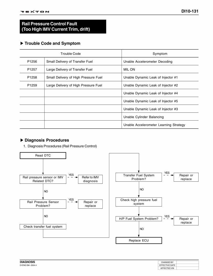
DI10-131
CHANGED BY
EFFECTIVE DATE
AFFECTED VIN
DIAGNOSISDI ENG SM - 2004.4
Trouble Code and Symptom
Diagnosis Procedures1. Diagnosis Procedures (Rail Pressure Control)
Rail Pressure Control Fault(Too High IMV Current Trim, drift)
Small Delivery of Transfer Fuel
Large Delivery of Transfer Fuel
Small Delivery of High Pressure Fuel
Large Delivery of High Pressure Fuel
Trouble Code Symptom
P1256
P1257
P1258
P1259
Unable Accelerometer Decoding
MIL ON
Unable Dynamic Leak of Injector #1
Unable Dynamic Leak of Injector #2
Unable Dynamic Leak of Injector #4
Unable Dynamic Leak of Injector #5
Unable Dynamic Leak of Injector #3
Unable Cylinder Balancing
Unable Accelerometer Learning Strategy
YES
YES
Read DTC
Rail preaaure sensor or IMVRelated DTC?
NO
Rail Pressure SensorProblem?
Check transfer fuel system
NO
Replace ECU
Refer to IMVdiagnosis
Repair orreplace
YES
YES
Transfer Fuel SystemProblem?
Check high pressure fuelsystem
NO
H/P Fuel System Problem?
Repair orreplace
Repair orreplace
NO

DI10-132
CHANGED BY
EFFECTIVE DATE
AFFECTED VIN
DIAGNOSISDI ENG SM - 2004.4
YES
YES
2. Diagnosis Procedures (Transfer Fuel System)
YES
YES
Check fuel level
Fuel Exhausted?
“Visually check transfer fuelsystem (fuel leaks, installation)”
NO
Transfer Fuel SystemProblem?
NO
Check fuel filter specification
Different Specification?
NO
Repiar Completed
Add fuel
Repair orreplace
Replace filterwith new one
NO
Check if the air in transferfuel system is too much
Excessive Air in TransferFuel System?
NO
Install acontainer toH/P pump
venturi.Remove
venturi returnlines. Fill fuel
with handpump.
3. Diagnosis Procedures (High Pressure Fuel System)
YES
Check transfer fuel system
Cause Found?
NO
Repair orreplace
H/P Fuel System - Normal

DI10-133
CHANGED BY
EFFECTIVE DATE
AFFECTED VIN
DIAGNOSISDI ENG SM - 2004.4
Unable Accelerometer Decoding
Unable Dynamic Leak of Injector #1
Unable Dynamic Leak of Injector #2
Unable Dynamic Leak of Injector #4
Unable Dynamic Leak of Injector #5
Unable Dynamic Leak of Injector #3
Unable Cylinder Balancing
Unable Accelerometer Learning Strategy
Limited Rail Pressure Mode Operation
Trouble Code and Symptom
Diagnosis Procedures1. Diagnosis Procedures (Rail Pressure Control)
Rail Pressure Control Fault (Too SlowPressure Build Up while Cranking)
Rail Pressure Build Up - Too Slow
Trouble Code Symptom
P1191
YES
YES
Read DTC
Rail preaaure sensor or IMVRelated DTC?
NO
Rail Pressure SensorProblem?
Check transfer fuel system
NO
Replace ECU
Refer to IMVdiagnosis
Repair orreplace
YES
YES
Transfer Fuel SystemProblem?
Check high pressure fuelsystem
NO
H/P Fuel System Problem?
Repair orreplace
Repair orreplace
NO

DI10-134
CHANGED BY
EFFECTIVE DATE
AFFECTED VIN
DIAGNOSISDI ENG SM - 2004.4
YES
YES
2. Diagnosis Procedures (Transfer Fuel System)
YES
YES
Check fuel level
Fuel Exhausted?
“Visually check transfer fuelsystem (fuel leaks, installation)”
NO
Transfer Fuel SystemProblem?
NO
Check fuel filter specification
Different Specification?
NO
Transfer fuel system is normal
Add fuel
Repair orreplace
Replace filterwith new one
NO
Check if the air in transferfuel system is too much (with
a low pressure tester)
Excessive Air in TransferFuel System?
NO
Install acontainer toH/P pump
venturi.Remove
venturi returnlines. Fill fuel
with handpump.
3. Diagnosis Procedures (High Pressyre Fuel System)
YES
Check transfer fuel system
Cause Found?
NO
Repair orreplace
HP fuel system is normal

DI10-135
CHANGED BY
EFFECTIVE DATE
AFFECTED VIN
DIAGNOSISDI ENG SM - 2004.4
Unable Accelerometer Decoding
Delayed Engine Stop
Unable Dynamic Leak of Injector #1
Unable Dynamic Leak of Injector #2
Unable Dynamic Leak of Injector #4
Unable Dynamic Leak of Injector #5
Unable Dynamic Leak of Injector #3
Unable Cylinder Balancing
Unable H/P Leak Detection
Unable Accelerometer Learning Strategy
Limited Rail Pressure Mode Operation
Trouble Code and Symptom
Diagnosis Procedures
IMV Operation Fault (Electrical Fault)
Open Circuit
Short Circuit
Short to Ground
Trouble Code Symptom
P0255
P0251
P0253
YES
Check IMV wiring
Wiring Problem?
Replace ECU
Repair orreplace
YES
Check resistance of IMV
NO
Resistance Problem? Replace H/Ppump and IMV
NO
YES
Check ECU wiring
NO
Wiring Problem? Repair orreplace
YES
Check wiring and insulation
NO
Wiring Problem? Repair wiring

DI10-136
CHANGED BY
EFFECTIVE DATE
AFFECTED VIN
DIAGNOSISDI ENG SM - 2004.4
Trouble Code and Symptom
Diagnosis Procedures
Intake Air Temperature Sensor Fault(Electric Fault)
High
Low
Supply Voltage
Trouble Code Symptom
P0112
P0113
P0110
MIL ON
YES
YES
YES
YES
Read DTC
Fault in sensor supply voltage?
Check sensor wiring
NO
Wiring Problem?
Check sensor resistance
NO
Check ECU wiring
Wiring Problem?
Check wiring and insulation
NO
Wiring Problem?
Replace ECU
NO
Repair orreplace
Sensor problem caused by supply voltageto sensor. Locate the problem while dis-connecting the sensor connectors one byone. If not sensor problem, check sensorsupply voltage circuit for open and short.
Repair orreplace
Repair wiring
NO
YESResistance Problem? Replace
sensor
NO

DI10-137
CHANGED BY
EFFECTIVE DATE
AFFECTED VIN
DIAGNOSISDI ENG SM - 2004.4
Trouble Code and Symptom
Diagnosis Procedures
MDP Fault (Injector #1)
#1 Injector MDP Fault
Trouble Code Symptom
P1171 Unable Accelerometer Decoding
MIL ON
Unable Pilot and Post Injection
Unable Dynamic Leak of Injector #1
Torque Limit For Injector Drift
Unable Accelerometer Learning Strategy
Enter the injector data intoECU after replacing injector
Trouble Code and Symptom
Diagnosis Procedures
MDP Fault (Injector #2)
#2 Injector MDP Fault
Trouble Code Symptom
P1172 Unable Accelerometer Decoding
MIL ON
Unable Pilot and Post Injection
Unable Dynamic Leak of Injector #2
Torque Limit For Injector Drift
Unable Accelerometer Learning Strategy
Enter the injector data intoECU after replacing injector

DI10-138
CHANGED BY
EFFECTIVE DATE
AFFECTED VIN
DIAGNOSISDI ENG SM - 2004.4
Trouble Code and Symptom
Diagnosis Procedures
MDP Fault (Injector #4)
#4 Injector MDP Fault
Trouble Code Symptom
P1174 Unable Accelerometer Decoding
MIL ON
Unable Pilot and Post Injection
Unable Dynamic Leak of Injector #4
Torque Limit For Injector Drift
Unable Accelerometer Learning Strategy
Enter the injector data intoECU after replacing injector
Trouble Code and Symptom
Diagnosis Procedures
MDP Fault (Injector #5)
#5 Injector MDP Fault
Trouble Code Symptom
P1175 Unable Accelerometer Decoding
MIL ON
Unable Pilot and Post Injection
Unable Dynamic Leak of Injector #5
Torque Limit For Injector Drift
Unable Accelerometer Learning Strategy
Enter the injector data intoECU after replacing injector

DI10-139
CHANGED BY
EFFECTIVE DATE
AFFECTED VIN
DIAGNOSISDI ENG SM - 2004.4
Trouble Code and Symptom
Diagnosis Procedures
MDP Fault (Injector #3)
#3 Injector MDP Fault
Trouble Code Symptom
P1173 Unable Accelerometer Decoding
MIL ON
Unable Pilot and Post Injection
Unable Dynamic Leak of Injector #3
Torque Limit For Injector Drift
Unable Accelerometer Learning Strategy
Enter the injector data intoECU after replacing injector

DI10-140
CHANGED BY
EFFECTIVE DATE
AFFECTED VIN
DIAGNOSISDI ENG SM - 2004.4
Trouble Code and Symptom
Diagnosis Procedures1. Diagnosis Procedures (Rail Pressure Control)
Rail Pressure Fault (Too High)
Too High IMV Pressure
Trouble Code Symptom
P1252
YES
YES
Read DTC
Rail preaaure sensor or IMVRelated DTC?
Rail Pressure SensorProblem?
Check transfer fuel system
Replace ECU
Refer toIMV diagnosis
Repair orreplace
YES
Check high pressure fuelsystem
NO
H/P Fuel System Problem? Repair orreplace
NO
NO
NO
YESTransfer Fuel System
Problem?Repair orreplace

DI10-141
CHANGED BY
EFFECTIVE DATE
AFFECTED VIN
DIAGNOSISDI ENG SM - 2004.4
YES
YES
2. Diagnosis Procedures (Transfer Fuel System)
YES
YES
Check fuel level
Fuel Exhausted?
“Visually check transfer fuelsystem (fuel leaks, installation)”
NO
Transfer Fuel SystemProblem?
NO
Check fuel filter specification
Different Specification?
NO
Repiar Completed
Add fuel
Repair orreplace
Replace filterwith new one
NO
Check if the air in transferfuel system is too much (with
a low pressure tester)
Excessive Air in TransferFuel System?
Install acontainer toH/P pump
venturi.Remove
venturi returnlines. Fill fuel
with handpump.
3. Diagnosis Procedures (High Pressyre Fuel System)
YES
Check transfer fuel system
Cause Found?
NO
Repair orreplace
HP fuel system is normal

DI10-142
CHANGED BY
EFFECTIVE DATE
AFFECTED VIN
DIAGNOSISDI ENG SM - 2004.4
YESReplacesensor
Trouble Code and Symptom
Diagnosis Procedures
Accelerator Pedal Sensor 1 Malfunction
Accelerator Pedal Sensor 2 Malfunction
Trouble Code Symptom
P1120
P1121
Unable Cruise Control
Torque Reduction Mode Operation
YES
YES
YES
YES
Read DTC
Fault in sensor supply voltage?
Sensor Wiring Problem?
NO
Wiring Problem?
Visually check sensor
NO
Check ECU wiring
Wiring Problem?
Check wiring and insulation
NO
Wiring Problem?
Repiar Completed
NO
Repair orreplace
Sensor problem caused by supply voltageto sensor. Locate the problem while dis-connecting the sensor connectors one byone. If not sensor problem, check sensorsupply voltage circuit for open and short.
Repair orreplace
Repair wiring
NO
YESSensor Problem? Replace
sensor
NO
YES
Replace sensor
Trouble Continues?
NO
Replace ECU
Accelerator Pedal Sensor Malfunction(Relationship between Track 1 and Track 2)

DI10-143
CHANGED BY
EFFECTIVE DATE
AFFECTED VIN
DIAGNOSISDI ENG SM - 2004.4
YESReplacesensor
Trouble Code and Symptom
Diagnosis Procedures
Accelerator Pedal Sensor Malfunction(Limp Home Mode Operation)
Accelerator Pedal Sensor Malfunction (Limp
Home Mode)
Trouble Code Symptom
P1122 MIL ON
Limp Home Mode Operation
YES
YES
YES
YES
Read DTC
Fault in sensor supply voltage?
Check sensor wiring
NO
Wiring Problem?
Visually check sensor
NO
Check ECU wiring
Wiring Problem?
Check wiring and insulation
NO
Wiring Problem?
Repiar Completed
NO
Repair orreplace
Sensor problem caused by supply voltageto sensor. Locate the problem while dis-connecting the sensor connectors one byone. If not sensor problem, check sensorsupply voltage circuit for open and short.
Repair orreplace
Repair wiring
NO
YESSensor Problem? Replace
sensor
NO
YES
Replace sensor
Trouble Continues?
NO
Replace ECU

DI10-144
CHANGED BY
EFFECTIVE DATE
AFFECTED VIN
DIAGNOSISDI ENG SM - 2004.4
YESReplacesensor
Trouble Code and Symptom
Diagnosis Procedures
Accelerator Pedal Sensor Malfunction(Torque Reduction Mode Operation)
Accelerator Pedal Sensor Malfunction (Torque
Mode)
Trouble Code Symptom
P1123 MIL ON
Torque Reduction Mode Operation
YES
YES
YES
YES
Read DTC
Fault in sensor supply voltage?
Check sensor wiring
NO
Wiring Problem?
Visually check sensor
NO
Check ECU wiring
Wiring Problem?
Check wiring and insulation
NO
Wiring Problem?
Repiar Completed
NO
Repair orreplace
Sensor problem caused by supply voltageto sensor. Locate the problem while dis-connecting the sensor connectors one byone. If not sensor problem, check sensorsupply voltage circuit for open and short.
Repair orreplace
Repair wiring
NO
YESSensor Problem? Replace
sensor
NO
YES
Replace sensor
Trouble Continues?
NO
Replace ECU

DI10-145
CHANGED BY
EFFECTIVE DATE
AFFECTED VIN
DIAGNOSISDI ENG SM - 2004.4
Trouble Code and Symptom
Diagnosis Procedures
Accelerator Pedal Sensor Malfunction(Electrical Fault, Pedal Stuck)
Accelerator Pedal Sensor Malfunction - Stuck
Trouble Code Symptom
P1124 Unable Cruise Control
Limp Home Mode Operation
YES
YES
YES
Read DTC
Brake switch malfunction
Check if accelerator pedal isnormal
NO
Accelerator Pedal Stuck?
Check if accelerator pedalsignal is correct with scan tool
NO
Signal Problem?
Repiar Completed
Repair orreplace brake
switch.
Replaceaccelerator
pedal
Repair orreplace
NO
YES
Check brake wiring connection
NO
Wiring Problem? Repair orreplace
YES
YES
Check ECU wiring
NO
Wiring Problem?
Check wiring insulation
NO
Wiring Problem?
Repair orreplace
Repair wiring
YES
Replace brake switch
NO
Trouble Continues? Replace ECU

DI10-146
CHANGED BY
EFFECTIVE DATE
AFFECTED VIN
DIAGNOSISDI ENG SM - 2004.4
Trouble Code and Symptom
Diagnosis Procedures
Accelerator Pedal Sensor Malfunction(Electrical Fault, Track 1)
Low
High
Supply Voltage
Trouble Code Symptom
P0122
P0123
P0120
MIL ON
Unable Cruise Control
Limp Home Mode Operation
YES
YES
YES
YES
Read DTC
Fault in sensor supply voltage?
Check sensor wiring
NO
Wiring Problem?
Visually check sensor
NO
Check ECU wiring
Wiring Problem?
Check wiring and insulation
NO
Wiring Problem?
Repiar Completed
NO
Repair orreplace
Sensor problem caused by supply voltageto sensor. Locate the problem while dis-connecting the sensor connectors one byone. If not sensor problem, check sensorsupply voltage circuit for open and short.
Repair orreplace
Repair wiring
NO
YESSensor Problem? Replace
sensor
NO
YES
Replace sensor
Trouble Continues?
NO
Replace ECU

DI10-147
CHANGED BY
EFFECTIVE DATE
AFFECTED VIN
DIAGNOSISDI ENG SM - 2004.4
Trouble Code and Symptom
Diagnosis Procedures
Accelerator Pedal Sensor Malfunction(Electrical Fault, Track 2)
Low
High
Supply Voltage
Trouble Code Symptom
P0222
P0223
P0220
YES
YES
YES
YES
Read DTC
Fault in sensor supply voltage?
Check sensor wiring
NO
Wiring Problem?
Visually check sensor
NO
Check ECU wiring
Wiring Problem?
Check wiring and insulation
NO
Wiring Problem?
Repiar Completed
NO
Repair orreplace
Sensor problem caused by supply voltageto sensor. Locate the problem while dis-connecting the sensor connectors one byone. If not sensor problem, check sensorsupply voltage circuit for open and short.
Repair orreplace
Repair wiring
NO
YESSensor Problem? Replace
sensor
NO
YES
Replace sensor
Trouble Continues?
NO
Replace ECU
MIL ON
Unable Cruise Control
Torque Reduction Mode Operation

DI10-148
CHANGED BY
EFFECTIVE DATE
AFFECTED VIN
DIAGNOSISDI ENG SM - 2004.4
Unable Pilot and Post Injection
Unable Dynamic Leak of Injector #1
Unable Dynamic Leak of Injector #2
Unable Dynamic Leak of Injector #4
Unable Dynamic Leak of Injector #5
Unable Dynamic Leak of Injector #3
Unable RPC Trim Fault Detection
Unable Cylinder Balancing
Unable H/P Leak Detection
Unable Accelerometer Learning Strategy
Fully Forced Open IMV
Limited Rail Pressure Mode Operation
Unable High Rail Pressure Detection
Torque Reduction Mode Operation
Trouble Code and Symptom
Fuel Rail Pressure Sensor Malfunction(Out of Range, ADC or Vref)
Low
High
Supply Voltage
Excessive Pressure Drop
Trouble Code Symptom
P0192
P0193
P0190
P0191

DI10-149
CHANGED BY
EFFECTIVE DATE
AFFECTED VIN
DIAGNOSISDI ENG SM - 2004.4
Diagnosis Procedures
YES
YES
YES
YES
Read DTC
Sensor Voltage Fault?
Check sensor wiring(Check sensor output)
NO
Wiring Problem?
Check ECU wiring
NO
Check wiring and insulation
Wiring Problem?
Replace rail and sensor
Trouble Continues?
Check fuel system
NO
Repair orreplace
Sensor problem caused by supply voltageto sensor. Locate the problem while dis-connecting the sensor connectors one byone. If not sensor problem, check sensorsupply voltage circuit for open and short.
Repair wiring
Replace ECU
NO
YESWiring Problem? Repair or
replace
NO

DI10-150
CHANGED BY
EFFECTIVE DATE
AFFECTED VIN
DIAGNOSISDI ENG SM - 2004.4
Unable Pilot and Post Injection
Unable Dynamic Leak of Injector #1
Unable Dynamic Leak of Injector #2
Unable Dynamic Leak of Injector #4
Unable Dynamic Leak of Injector #5
Unable Dynamic Leak of Injector #3
Unable RPC Trim Fault Detection
Unable Cylinder Balancing
Unable H/P Leak Detection
Unable Accelerometer Learning Strategy
Fully Forced Open IMV
Limited Rail Pressure Mode Operation
Unable High Rail Pressure Detection
Torque Reduction Mode Operation
Trouble Code and Symptom
Fuel Rail Pressure Sensor Malfunction(Out of Range when Key ON)
Low
High
Supply Voltage
Trouble Code Symptom
P1192
P1193
P1190

DI10-151
CHANGED BY
EFFECTIVE DATE
AFFECTED VIN
DIAGNOSISDI ENG SM - 2004.4
Diagnosis Procedures
YES
YES
Check sensor wiring
Wiring Problem?
Wiring Problem?
Check resistance of wiring
Repair completed
Repair orreplace
Repair orreplace
YES
Reinstall connect and wiring
NO
Trouble Continues? Replace railand sensor
NO
NO
NO
YESWiring Problem? Repair wiring
Check ECU wiring

DI10-152
CHANGED BY
EFFECTIVE DATE
AFFECTED VIN
DIAGNOSISDI ENG SM - 2004.4
Trouble Code and Symptom
Diagnosis Procedures
Main Relay Malfunction - Stuck
Main Relay Malfunction- Stuck
Trouble Code Symptom
P0215 MIL ON
YES
YES
YES
Check relay wiring
Wiring Problem?
Check ECU wiring
NO
Wiring Problem?
NO
Perform forced operationand replace relay
Not available forcedoperation?
NO
Repair completed
Repair orreplace
Repair orreplace
Replace ECU
NO
YES
Check wiring and insulation
Wiring Problem? Repair wiring

DI10-153
CHANGED BY
EFFECTIVE DATE
AFFECTED VIN
DIAGNOSISDI ENG SM - 2004.4
Trouble Code and Symptom
Diagnosis Procedures
Vehicle Speed Fault
Vehicle Speed Fault
Trouble Code Symptom
P1500 Unable Cruise Control
YES
YES
YES
Check vehicle conditions
Automatic TransmissionEquipped?
Check sensor and wiring
NO
Wiring Problem?
Check ECU wiring
NO
Wiring Problem? Repair completed
Recognizevehicle speedthrough CAN.Check CAN
andtransmission.
Repair orreplace
Repair orreplace
YES
Check wiring and insulation
NO
Wiring Problem? Repair orreplace
YES
YES
Check gear box target
Gear Box Target Problem?
Install new target
NO
Trouble Continues?
Replace gearbox target
Replace ECU
NO
NO

DI10-154
CHANGED BY
EFFECTIVE DATE
AFFECTED VIN
DIAGNOSISDI ENG SM - 2004.4
Trouble Code and Symptom
Diagnosis Procedures
5V Supply Voltage 1 Fault
Low
High
Supply Voltage
Trouble Code Symptom
P0642
P0643
P0641
Unable Cruise Control
YES
YES
Supply Voltage 1 (5V):Accelerator Pedal Sensor 1
“Supply Voltage 2 (5V): HFMsensor, Rail pressure
sensor, Boost pressuresensor and Cam sensor”
Supply Voltage (2.5 V): Accelera-tor Pedal Sensor 2
Read DTC
All DTCs for sensorsconnected to sensor supply
voltage?
Check wiring
NO
Trouble Continues?
NO
Repair completed
Sensor problem caused by supply voltage tosensor. Locate the problem while discon-necting the sensor one by one. If not sensorproblem, check wiring.
Replace ECU

DI10-155
CHANGED BY
EFFECTIVE DATE
AFFECTED VIN
DIAGNOSISDI ENG SM - 2004.4
Trouble Code and Symptom
Diagnosis Procedures
5V Supply Voltage 2 Fault
Low
High
Supply Voltage
Trouble Code Symptom
P0652
P0653
P0651
YES
YES
Supply Voltage 1 (5 V):Accelerator Pedal Sensor 1
“Supply Voltage 2 (5 V): HFMsensor, Rail pressure
sensor, Boost pressuresensor and Cam sensor”
Supply Voltage (2.5 V): Accelera-tor Pedal Sensor 2
Read DTC
All DTCs for sensorsconnected to sensor supply
voltage?
Check wiring
NO
Trouble Continues?
NO
Repair completed
Sensor problem caused by supply voltageto sensor. Locate the problem while dis-connecting the sensor one by one. If notsensor problem, check wiring.
Replace ECU

DI10-156
CHANGED BY
EFFECTIVE DATE
AFFECTED VIN
DIAGNOSISDI ENG SM - 2004.4
Trouble Code and Symptom
Diagnosis Procedures
2.5V Supply Voltage Fault
Low
High
Supply Voltage
Trouble Code Symptom
P0698
P0699
P0697
Unable Cruise Control
YES
YES
Supply Voltage 1 (5 V):Accelerator Pedal Sensor 1
“Supply Voltage 2 (5 V): HFMsensor, Rail pressure
sensor, Boost pressuresensor and Cam sensor”
Supply Voltage (2.5 V):Accelerator Pedal Sensor 2
Read DTC
All DTCs for sensorsconnected to sensor supply
voltage?
Check wiring
NO
Trouble Continues?
NO
Repair completed
Sensor problem caused by supply voltageto sensor. Locate the problem while dis-connecting the sensor one by one. If notsensor problem, check wiring.
Replace ECU

DI10-157
CHANGED BY
EFFECTIVE DATE
AFFECTED VIN
DIAGNOSISDI ENG SM - 2004.4
Trouble Code and Symptom
Diagnosis Procedures
Turbo Charger Actuator Operation Fault(signal)
Short to GND
Short Circuit to B+
Trouble Code Symptom
P0245
P0246
Unable Cruise Control
Unable VGT Operation
YES
YES
YES
Check actuator wiring
Wiring Problem?
Check resistance of actuator
NO
Resistance Problem?
Check EUC wiring
NO
Wiring Problem?
Repair completed
Repair orreplace
Replaceactuator
Repair orreplace
YES
Check wiring and insulation
NO
Wiring Problem? Repair wiring
YES
Replace actuator
Trouble Continues?
NO
Replace ECU
NO
NO

DI10-158
CHANGED BY
EFFECTIVE DATE
AFFECTED VIN
DIAGNOSISDI ENG SM - 2004.4
Trouble Code and Symptom
Diagnosis Procedures
ECU Watchdog Fault
ECU Watchdog Fault
Trouble Code Symptom
P0606
YES
YES
Read DTC
ECU Related DTC?
Check wiring
NO
Trouble Continues?
NO
Repair completed
Check bodyground wiring
Replace ECU

DI10-159
CHANGED BY
EFFECTIVE DATE
AFFECTED VIN
DIAGNOSISDI ENG SM - 2004.4
Trouble Code and Symptom
Diagnosis Procedures
ECU Watchdog Fault (Injector Cut-off)
ECU Injector Cut-off
Trouble Code Symptom
P1607
YES
YES
Read DTC
ECU Related DTC?
Check wiring
NO
Trouble Continues?
NO
Repair completed
Check bodyground wiring
Replace ECU

DI10-160
CHANGED BY
EFFECTIVE DATE
AFFECTED VIN
DIAGNOSISDI ENG SM - 2004.4
Trouble Code and Symptom
Diagnosis Procedures
ECU Watchdog Fault (Watchdog Trip)
Trip TPU Write Fault
Trip Shut Dowm Write Fault
Trip Noise Write Fault
Trouble Code Symptom
P1600
P1601
P1602
YES
YES
Read DTC
ECU Related DTC?
Check wiring
NO
Trouble Continues?
NO
Repair completed
Check bodyground wiring
Replace ECU

DI10-161
CHANGED BY
EFFECTIVE DATE
AFFECTED VIN
DIAGNOSISDI ENG SM - 2004.4
Trouble Code and Symptom
Diagnosis Procedures
ECU Non-Volatile Memory Fault
MDP
Tele-Coding
Watchdog
CAN
ECU Malfunction
ECU Malfunction
ECU Malfunction
Trouble Code Symptom
P1614
P1615
P1616
P1606
P1620
P1621
P1622
MIL ON/Limp Home Mode Operation
MIL ON/Limp Home Mode Operation
MIL ON/Limp Home Mode Operation
MIL ON/Limp Home Mode Operation
MIL ON/Limp Home Mode Operation
MIL ON/Limp Home Mode Operation
MIL ON
YES
YES
Read DTC
ECU Related DTC?
Check wiring
NO
Trouble Continues?
NO
Repair completed
Check bodyground wiring
Replace ECU

DI10-162
CHANGED BY
EFFECTIVE DATE
AFFECTED VIN
DIAGNOSISDI ENG SM - 2004.4
Trouble Code and Symptom
Diagnosis Procedures
ECU Memory Integration Fault
Code Integrity
Code Integrity
Code Integrity
Trouble Code Symptom
P1603
P1604
P1605
Immediately Engine Stop
Immediately Engine Stop
Immediately Engine Stop
YES
YES
Read DTC
ECU Related DTC?
Check wiring
NO
Trouble Continues?
NO
Repair completed
Check bodyground wiring
Replace ECU

DI10-163
CHANGED BY
EFFECTIVE DATE
AFFECTED VIN
DIAGNOSISDI ENG SM - 2004.4
Trouble Code and Symptom
Diagnosis Procedures
Accelerometer Learning Fault
Accelerometer (Knock Sensor) Learning Fault
Trouble Code Symptom
P1148 Torque Reduction Operation
Unable Cruise Control
YES
Read DTC
Knock Sensor Related DTC?
NO
Vehicl driving conditions arenot satisfy with MDP learning
requirements
Refer to“Accelerom-eter (Knock
Sensor)Diagnosis”

DI10-164
CHANGED BY
EFFECTIVE DATE
AFFECTED VIN
DIAGNOSISDI ENG SM - 2004.4
Trouble Code and Symptom
Diagnosis Procedures
EGR Valve Control Fault
EGR Valve Control Fault
Trouble Code Symptom
P0400 Unable Cruise Control
YES
Read DTC
EGR valve and HFM sensorrelated DTC?
NO
Check vacuum modulator/turbo charger boost modula-tor and vacuum lines for leak
and installation
Repair completed
Checksensors andEGR system

DI10-165
CHANGED BY
EFFECTIVE DATE
AFFECTED VIN
DIAGNOSISDI ENG SM - 2004.4
Trouble Code and Symptom
Diagnosis Procedures1. Diagnosis Procedures(Boost Pressure)
VGT Operation Fault
VGT Operation Fault
Trouble Code Symptom
P1235 Unable Cruise Control
Location demand=change the boost control to O.L.
mode at f (boost demand, engine cycling speed)
YES
Read DTC
Boost Pressure Problem?
NO
Check air line malfunction:* VGT/Turbo. * Air filter.
* Vacuum line. * Vacuum pump.* Solenoid valve open.
* Vane condition.* Air inlet valve function
Repair completed
Refer toDiagnosis
Tree “Checksensor(1)”

DI10-166
CHANGED BY
EFFECTIVE DATE
AFFECTED VIN
DIAGNOSISDI ENG SM - 2004.4
2. Diagnosis Procedures(Check sensor (1))
YES
YES
YES
YES
Read DTC
Sensor Supply VoltageProblem?
Check sensor wiring
NO
Wiring Problem?
Visually check sensor
NO
Check ECU wiring
Wiring Problem?
Check wiring and insulation
Wiring Problem?
Check fuel system
NO
Repair orreplace
Sensor problem caused by supply voltageto sensor. Locate the problem while dis-connecting the sensor connectors one byone. If not sensor problem, check sensorsupply voltage circuit for open and short.
Repair orreplace
Repair orreplace
NO
YESSensor Problem? Replace
sensor
NO
YES
Replace sensor
Trouble Continues?
NO
Replace ECU

DI10-167
CHANGED BY
EFFECTIVE DATE
AFFECTED VIN
DIAGNOSISDI ENG SM - 2004.4
Trouble Code and Symptom
Diagnosis Procedures
TBD
ECU Malfunction
Trouble Code Symptom
P1608
YES
YES
Read DTC
ECU Related DTC?
Check wiring
NO
Trouble Continues?
NO
Repair completed
Check bodyground wiring
Replace ECU

DI10-168
CHANGED BY
EFFECTIVE DATE
AFFECTED VIN
DIAGNOSISDI ENG SM - 2004.4
Trouble Code and Symptom
Diagnosis Procedures
No Crank Signal
No Crank Signal
Trouble Code Symptom
P0335 MIL ON
YES
YES
YES
Check sensor wiring
Wiring Problem?
Check ECU wiring
NO
Wiring Problem?
Check wiring for open andshort
Wiring Problem?
Repair completed
Repair orreplace
Repair orreplace
Repair wiring
YES
NO
Trouble Continues? Replace VRsensor
YES
Install new wheel
Trouble Continues?
NO
Replace ECU
NO
Install new sensor
NO
YESTrouble Continues? Replace APS
wheel
NO

DI10-169
CHANGED BY
EFFECTIVE DATE
AFFECTED VIN
DIAGNOSISDI ENG SM - 2004.4
Trouble Code and Symptom
Diagnosis Procedures
High Torque Trim
High Torque Trim
Trouble Code Symptom
P1170 MIL ON
YES
YES
YES
Read DTC
IMV Related DTC?
Read DTC
NO
Rail Pressure SensorProblem?
Check transfer pressure fuelsystem
Transfer pressure fuelsystem Problem?
Replace ECU
Refer to IMVdiagnosis
Repair orreplace
Repair orreplace
YES
Check high pressure fuelsystem
High pressure fuel systemProblem?
NO
Repair orreplace
NO
NO
* Refer to “Check High and Transfer pressure system”.

DI10-170
CHANGED BY
EFFECTIVE DATE
AFFECTED VIN
DIAGNOSISDI ENG SM - 2004.4
YES
Trouble Code and Symptom
Diagnosis Procedures
Glow Plug Module Communication Fault
Communication
Controller
Trouble Code Symptom
P1676
P1677
YES
YES
Read DTC
Poor Glow PlugCommunication?
Check glow plug box wiring
NO
Wiring Problem?
Check glow plug and wiring(Resistance: below 1 Ω)
Problems?Repair completed
Communica-tion problembetween ECUand glow plug
box. Checkrelated wirings.
Repair orreplace
Repair orreplace glow
plug
YES
Replace glow plug box
Trouble Continues?
NO
Replace ECU
NO
YESWiring Problem? Repair wiring
NO
YES
Check ECU wiring
NO
Wiring Problem? Repair orreplace
Check wiring and insulation
NO

DI10-171
CHANGED BY
EFFECTIVE DATE
AFFECTED VIN
DIAGNOSISDI ENG SM - 2004.4
YES
Trouble Code and Symptom
Diagnosis Procedures
Glow Plug Module Circuit Malfunction -Open
Glow Plug #1
Glow Plug #2
Glow Plug #3
Glow Plug #4
Glow Plug #5
Trouble Code Symptom
P0671
P0672
P0673
P0674
P0675
YES
YES
Read DTC
Poor Glow PlugCommunication?
Check glow plug box wiring
NO
Wiring Problem?
Check glow plug and wiring(Resistance: below 1 Ω)
Problems?
Repair completed
Communica-tion problembetween ECUand glow plug
box. Checkrelated wirings.
Repair orreplace
Repair orreplace glow
plug
YES
Replace glow plug box
Trouble Continues?
NO
Replace ECUNO
YESWiring Problem? Repair wiring
NO
YES
Check ECU wiring
NO
Wiring Problem? Repair orreplace
Check wiring and insulation
NO

DI10-172
CHANGED BY
EFFECTIVE DATE
AFFECTED VIN
DIAGNOSISDI ENG SM - 2004.4
YES
Trouble Code and Symptom
Diagnosis Procedures
Glow Plug Module Circuit Malfunction -Short (B+)
Glow Plug #1
Glow Plug #2
Glow Plug #3
Glow Plug #4
Glow Plug #5
Trouble Code Symptom
P1671
P1672
P1673
P1674
P1675
YES
YES
Read DTC
Poor Glow PlugCommunication?
Check glow plug box wiring
NO
Wiring Problem?
Check glow plug and wiring(Resistance: below 1 Ω)
Problems?
Repair completed
Communica-tion problembetween ECUand glow plug
box. Checkrelated wirings.
Repair orreplace
Repair orreplace glow
plug
YES
Replace glow plug box
Trouble Continues?
NO
Replace ECUNO
YESWiring Problem? Repair wiring
NO
YES
Check ECU wiring
NO
Wiring Problem? Repair orreplace
Check wiring and insulation
NO

DI10-173
CHANGED BY
EFFECTIVE DATE
AFFECTED VIN
DIAGNOSISDI ENG SM - 2004.4
Trouble Code and Symptom
Diagnosis Procedures
TCU Signal Fault
TCU Signal Fault
Trouble Code Symptom
P0700
YES
YES
Check ECU wiring
Wiring Problem?
Check wiring and insulation
NO
Wiring Problem?
NO
Repair completed
Repair orreplace
Repair wiring
YES
Check CAN communication(between High and Low: 120 Ω)
Communication problemcontinues
NO
Repair orreplace
(Replace TCU)

DI10-174
CHANGED BY
EFFECTIVE DATE
AFFECTED VIN
DIAGNOSISDI ENG SM - 2004.4
YES
Trouble Code and Symptom
Diagnosis Procedures
Air Conditioner Operating Circuit Fault
Open Circuit
Short to +Batt
Short to Ground
Trouble Code Symptom
P1540
P1541
P1542
Unable A/C Operation
Unable A/C Operation
Unable A/C Operation
YES
YES
Check vehicle condition(above fault is related to A/C
system)
Switch without sensor?
Check sensor connection
NO
Wiring Problem?
Check sensor
Sensor Problem?
Repair completed
N/A
Repair orreplace
Replacesensor
YES
Check A/C circuit andcompressor
A/C Problem?
NO
Repair orreplace
NO
YESWiring Problem? Repair wiring
NO
YES
Check ECU wiring
NO
Wiring Problem? Repair orreplace
Check wiring and insulation
NO
YES
Replace sensor
Trouble Continues?
NO
Replace ECU

DI10-175
CHANGED BY
EFFECTIVE DATE
AFFECTED VIN
DIAGNOSISDI ENG SM - 2004.4
YES
Trouble Code and Symptom
Diagnosis Procedures
Excessive Water in Fuel Filter
Excessive Water in Fuel Filter
Trouble Code Symptom
P1149 Water Separator Warning Light ON
Torque Reduction Mode Operation
YES
YES
Remove fuel filter
Water in fuel filter?
Check water detection sensor
NO
Wiring Problem?
Check water detectionsensor wiring
Wiring Problem? Replace ECU
Repaircompleted
Repair orreplace
Repair orreplace
YES
Check wiring and insulation
Wiring Problem?
NO
Repair wiring
NO
YESWiring Problem? Repair or
replace
NO
YES
Check resistance of waterdetection sensor
NO
Resistance Problem? Replacecoolant
temperaturesensor
Check ECU wiring
NO

DI10-176
CHANGED BY
EFFECTIVE DATE
AFFECTED VIN
DIAGNOSISDI ENG SM - 2004.4
Trouble Code and Symptom
Diagnosis Procedures
Immobilizer Malfunction
Immobilizer Malfunction
Trouble Code Symptom
P1634
P4335
P1630
P1631
P1632
P1633
P0633
P1636
MIL ON
Immobilizer Warning Light ON
YES
YES
Check immobilizer unitand ECU wiring
Wiring Problem?
NO
Perform immobilizer codingagain
NO
Repair or replace immobi-lizer unit and related devices
Repair orreplace
Repaircompleted

DI10-177
CHANGED BY
EFFECTIVE DATE
AFFECTED VIN
DIAGNOSISDI ENG SM - 2004.4
FUEL SYSTEM DIAGNOSIS
OVERVIEW ..............................................................DI10-178
Fuel pressure system ......................................... DI10-179
Fuel system pressure test .................................. DI10-182
Fuel system check process ................................ DI10-184

DI10-178
CHANGED BY
EFFECTIVE DATE
AFFECTED VIN
DIAGNOSISDI ENG SM - 2004.4
OVERVIEWWhen the Diagnostic Trouble Code (DTC) is detected through scan tool, it’s necessary to check the transfer and highpressure fuel lines in fuel system before replacing the components.
If the trouble continues even after the trouble has been fixed with scan tool, must perform the fuel pressure test.
Below schematic diagram shows the specifications of pressure, flow mass and temperature in fuel system.
Y220_10062
FUEL SYSTEM DIAGNOSIS
Transfer fuelpressure regulator
Pressure limit valve(High pressure line)
Transfer pump
Supplyvalve
Suctionvalve
High pressurepump
Up to1600 bar
Common rail
Injectors
Fuel tank
Priming pumpFuel filter
Venturi
Below 2 bar
Over - 0.48 bar
-0.6 ~ 0.1 bar
High pressure fuelsupply lineTransfer fuel supply line
Return line

DI10-179
CHANGED BY
EFFECTIVE DATE
AFFECTED VIN
DIAGNOSISDI ENG SM - 2004.4
FUEL PRESSURE SYSTEM
Y220_10063
Pressure/Volume Consumption in System Pressure/Volume Displacement from Pump
Injector backleak volume
Fuel injectionvolume
Pump capacity for
supplying the required
target pressure/volume
Conservation of fuel pressure/volume (rail) for proper systemoperation

DI10-180
CHANGED BY
EFFECTIVE DATE
AFFECTED VIN
DIAGNOSISDI ENG SM - 2004.4
Example of Too Much Injector Back leak
Too Much Injector Back leakWhen the injector cannot be sealed due to entering the foreign materials
Ex.:• Foreign materials in fuel
• Burnt out or worn high pressure pump
• Mechanical damage in inside of injector
Y220_10064
Increased injector back leak volume
Pressure/volume loss
Pump capacity
Pressure/volumebuild up
Pressure/volumeconsumption
Fuel injectionvolume
Injector backleak volume

DI10-181
CHANGED BY
EFFECTIVE DATE
AFFECTED VIN
DIAGNOSISDI ENG SM - 2004.4
Example of Pressure/Volume Loss in Pump
Pressure/Volume Loss in High Pressure PumpWhen the required target pressure/volume cannot be delivered due to fuel supply line or pump damage
Ex.:• Air in fuel supply line
• Excessive vacuum pressure in fuel supply line (-300 mbar)
• Burnt out or mechanically damaged pump
• Supply fuel with increased temperature ( > 65°C)
Y220_10065
Decreased pressure/volume frompump
Pressure/volume loss
Pump capacity
Pressure/volumebuild up
Pressure/volumeconsumption
Fuel injectionvolume
Injector backleak volume

DI10-182
CHANGED BY
EFFECTIVE DATE
AFFECTED VIN
DIAGNOSISDI ENG SM - 2004.4
FUEL SYSTEM PRESSURE TEST
Test Tool Kit
For High Pressure Line
For Transfer Line
Y220_10066
Y220_10067

DI10-183
CHANGED BY
EFFECTIVE DATE
AFFECTED VIN
DIAGNOSISDI ENG SM - 2004.4
Prerequisite1. Check the connections in fuel supply lines.
2. Check the fuel level in fuel tank.
3. Check if the air exists in fuel supply lines (air bubbles in fuel supply lines or fuel with air bubbles).
4. Check the fuel supply lines for leaks (transfer and high pressure).
5. Check if the specified fuel is used.
6. Check the fuel filter for contamination and abnormality.
Fuel System Test Process
Determine DTC
DTC Detected?
Fuel systemrelated DTC:
P1252, P1253,P1254...P0251
High pressure fuelrelated problem
No
No
Yes
noCheck and repair
transfer and H/P fuelsystem
Check fuel filter and H/Pfuel system
Diagnose and repairaccording to the de-
tected DTC
Notice
If more than one DTC have been detected, check the wiringharness for open or short first.
Check the transfer fuel system and fuel filter beforeproceeding the high pressure fuel system check in next page.

DI10-184
CHANGED BY
EFFECTIVE DATE
AFFECTED VIN
DIAGNOSISDI ENG SM - 2004.4
FUEL SYSTEM CHECK PROCESS
Initial Check• Transfer fuel system (air in system), specified fuel used
• Fuel leaks, fuel filter
• Diagnostic Trouble Code
• Wiring harness
• Abnormal noise from injector
No Abnormalityin Initial Check?
NoCheck and repair
No
Check transfer fuel system (refer to 4-2)
Install the transparent tube between fuelfilter and priming pump. Check the trans-fer fuel system for clogged or air bubbles.Check if the vacuum pressure is proper.
Check the injectorback leak volume
Replace high pressure pump
Yes
Yes
No
Yes
No
Yes
Yes
Replace the injector
Enter new injector C2I data into ECUafter replacing the injector
Replace the injector
Enter new injector C2I data into ECUafter replacing the injector
Perform the initial check again.
Method 1 Method 2
Dynamic Test for Injector Back leak Volume (refer to 4-4)
(with engine running)
1. Warm up engine (coolant temp.: over 60°C), place anempty plastic container under the return of injector, andstart engine.
2. Run the engine for 30 seconds at idle speed, perform :fuel system pressure leakage test” with Scan-i, andcheck the fuel level in container. It should be over 38 ml.
Check fuel rail pressure (refer to 4-1)
When cranking engine for 5 secondsafter disconnecting IMV connector, isthe rail pressure over 1,050 bar?
* Thoroughly clean the componentsbefore installation
High Pressure Pump Test (refer to 4-5)
Install the closed rail into high pressurepump at outlet port. Remove IMV connectorand crank engine for 5 seconds. Is the pres-sure over 1,050 bar?
Static Test for Injector Back leak Volume(refer to 4-3)
(with engine cranking but not running)
Place an empty plastic container under the return ofinjector:
Remove IMV and injector connectors, crank for 5seconds, and check the injector back leak volume.The fuel length in tube should be over 20 cm.
No

DI10-185
CHANGED BY
EFFECTIVE DATE
AFFECTED VIN
DIAGNOSISDI ENG SM - 2004.4
4-1. High Pressure System Pressure Test
Fuel Rail Pressure Test1. Disconnect the fuel rail pressure sensor connector and
IMV connector.
Y220_10068
Y220_10069
2. Install the pressure tester in tool kit to the fuel railpressure sensor connector.
Y220_10070
3. Crank the engine for 5 seconds (twice).
- Read the maximum pressure displayed on the tester.
- If the maximum pressure is below 1,050 bar, refer to“Fuel System Check Process” section.

DI10-186
CHANGED BY
EFFECTIVE DATE
AFFECTED VIN
DIAGNOSISDI ENG SM - 2004.4
How To Use Pressure Tester1. Check if the “TEST?” is displayed on the display when
pressing the “ ” button.
Note
The fuel rail pressure can be measured through the scantool.
Y220_10071
Y220_10072
2. The maximum pressure will be displayed when pressingthe button while cranking the engine (around 4 secondselapsed from 5 seconds).

DI10-187
CHANGED BY
EFFECTIVE DATE
AFFECTED VIN
DIAGNOSISDI ENG SM - 2004.4
4-2. Transfer Fuel System Test
Test Procedures1. All wiring harnesses, connectors and fuel lines should
be installed properly and the engine should be ready tostart.
2. Prepare the special tools for transfer fuel system testand thoroughly clean the system.
Y220_10073
Y220_10074
3. Disconnect the key connector for connecting the priming pump to fuel filter and install both connectors of thespecial tool to the fuel pump and the priming pump hoses.
4. Start the engine and visually check the transfer line for clogged and air bubbles while running the engine at idlespeed.
5. If the fuel flows are not smooth or air bubbles are found in fuel lines, locate the leaking area and correct it.

DI10-188
CHANGED BY
EFFECTIVE DATE
AFFECTED VIN
DIAGNOSISDI ENG SM - 2004.4
4-3. Static Test for Injector Back leak Volume1. Remove the injector return hose and seal the openings with screw type caps (included in tool kit).
2. Install the hoses from back leak test containers to returnnipples of injector.
Y220_10076
Y220_10077
Y220_10078
3. Disconnect the IMV connector in H/P pump and the fuelpressure sensor connector.

DI10-189
CHANGED BY
EFFECTIVE DATE
AFFECTED VIN
DIAGNOSISDI ENG SM - 2004.4
Specified value Below 20 cm
Y220_10079
If the measured value is out of specified value, replacethe injector.
Note
4. Crank the engine twice with 5 seconds of interval.
5. Check if the back leak volume meets the specification.

DI10-190
CHANGED BY
EFFECTIVE DATE
AFFECTED VIN
DIAGNOSISDI ENG SM - 2004.4
4-4. Dynamic Test for Injector Back leak Volume1. Start the engine and warm up until the coolant temperature reaches to 60°C.
2. Remove the injector return hose and seal the openings with screw type caps (included in tool kit).
3. Install the hoses from back leak test containers to returnnipples of injector.
Y220_10080
Y220_10081
4. Start the engine and let it run for 2 minutes at idle speed.
5. Check if the back leak volume meets the specification.
Specified value Below 38 ml
Y220_10082

DI10-191
CHANGED BY
EFFECTIVE DATE
AFFECTED VIN
DIAGNOSISDI ENG SM - 2004.4
1. When performing the static test for injector back leak Volume, the fuel pressure leakage test with Scan-i should bedone simultaneously. And, the fuel pressure leakage test with Scan-i can be done separately.
2. Test Conditions:
• No defective or faulty sensors and components in fuel system: checked by Scan-i
• Coolant temperature: over 60°C
3. The diagnosis procedures with Scan-i are as below:
1) Install the Scan-i to the diagnostic connector. Select“DIAGNOSTICS” and press “ENTER” in “MAIN MENU”screen. Select “REXTON” and press “ENTER” in “VEHICLESELECTION” screen.
2) Select “ECU” and press “ENTER” in “CONTROL UNITSELECTION” screen.
PRESSURE LEAKAGE TEST WITH SCAN-100
3) Select “LEAK DETECTION” and press “ENTER” in“FUNCTION SELECTION” screen.

DI10-192
CHANGED BY
EFFECTIVE DATE
AFFECTED VIN
DIAGNOSISDI ENG SM - 2004.4
4) If there are not any troubled conditions in “TESTCONDITION” screen, press “ENTER”.

DI10-193
CHANGED BY
EFFECTIVE DATE
AFFECTED VIN
DIAGNOSISDI ENG SM - 2004.4
4-5 High Pressure Pump Test1. Prepare the special tools for high pressure pump test
and thoroughly clean the system.
Y220_10083
Y220_10084
Y220_10085
Y220_10086
2. Remove the high pressure fuel supply pipe and installthe closed rail delivered with tool kit.
3. Install the opposite end of the closed rail into the fuel railfor test.
4. Remove the high pressure fuel return hose and installthe transparent tube between the high pressure pumpand the return port of fuel rail for test.
Specified value 40 Nm
Specified value 40 Nm
* The figure is to show the test method. However, the
actual test operation should be done while the high
pressure pump is installed in vehicle.

DI10-194
CHANGED BY
EFFECTIVE DATE
AFFECTED VIN
DIAGNOSISDI ENG SM - 2004.4
Y220_10087
5. Connect the digital tester connector into the sensorconnector of fuel rail for test.
6. Disconnect the IMV connector and the fuel rail pressuresensor connector.
7. Check if the measured value on the digital tester meetsthe specified value.
Specified value Over 1,050 bar
Y220_10088

REXTON (1 OF 2)ENGINE SERVICE MANUAL
TELEPHONE : 82-31-610-2740FACSIMILE : 82-31-610-3762
ISSUED BYINTERNATIONAL A/S TEAM
SSANGYONG MOTOR CO., LTD.
150-3, CHILGOI-DONG, PYUNGTAEK-SI
GYEONGGI-DO, 459-711 KOREA
NOTE:All rights reserved. Printed in SSANGYONG Motor Co., Ltd.No part of this book may be used or reproduced without thewritten permission of International A/S Team.