2012 brz engine service manual
TRANSCRIPT

PREPARATION MATERIALS PREPARATION MATERIALS PP
ENGINE ENGINE MECHANICAL EM
COOLING CO


PP
PREPARATION MATERIALS
PREPARATION MATERIALS
ENGINE MECHANICALSST . . . . . . . . . . . . . . . . . . . . . . . . . . . . . . . . . . . . . . . . . . . . . . . . . . . . . PP-1GENERAL TOOL . . . . . . . . . . . . . . . . . . . . . . . . . . . . . . . . . . . . . . . . . . . PP-4GREASE • OTHER . . . . . . . . . . . . . . . . . . . . . . . . . . . . . . . . . . . . . . . . . PP-5

PP–1Preparation materials - Engine mechanical
PP
Preparation materialsPreparation materialsENGINE MECHANICAL
SST
Illustration Tool number Description Remarks
18252AA000 Crankshaft socket Used for turning the crankshaft.
18355AA000 Pulley wrench • Used for removing and installing the crankshaft pulley.
• Used for removing and installing the water pump
pulley.• Used for removing and installing the camshaft
timing intake gear ASSY, and camshaft timing
exhaust gear ASSY.
18334AA030 Pulley wrench pin set • Used for removing and installing the water pump pulley.
• Used for removing and installing the camshaft
timing intake gear ASSY, and camshaft timing exhaust gear ASSY.
18270KA010 Socket Used for removing and installing the camshaft timing intake gear ASSY, and camshaft timing exhaust gear ASSY.
ST18252AA000
ST18355AA000
ST18334AA030
ST18270KA010

Preparation materials - Engine mechanicalPP–2
P
P18854AA000 Angle gauge • Used for tightening the cylinder head bolt.• Used for tightening the cylinder block bolt.
18334AA000 Pulley wrench pin set • Used for removing and installing the crankshaft pulley.
• Used for removing and installing the drive plate and ring gear SUB-ASSY, and flywheel SUB-ASSY.
18332AA20 Oil filer wrench Used for removing and installing the oil filter SUB-ASSY.
398437700 Oil seal installer Used for installing the timing chain/belt cover oil seal.
Illustration Tool number Description Remarks
ST18854AA000
ST18334AA000
ST18332AA020
ST-398437700

PP–3Preparation materials - Engine mechanical
PP
0920287002000 Remover and replacer Used for removing and installing the valve spring.
499765700 Valve guide remover and installer Used for removing and installing the valve guide busing No. 2.
18261AA010 Valve oil seal guide Used for press-fitting the intake valve guide stem seal, and exhaust valve guide stem seal.
18270AA020 Socket Used for removing and installing the connecting rod.
Illustration Tool number Description Remarks
ST0920287002000
ST-499765700
ST18261AA010
ST18270AA020

Preparation materials - Engine mechanicalPP–4
P
PGENERAL TOOL
18671AA020 Oil seal guide Used for installing the engine rear oil seal.
18657AA030 Oil seal installer Used for installing the engine rear oil seal.
Tool name Remarks
Union nut wrench (19 mm) Used for removing and installing the engine water temperature sensor.
Deep socket wrench (19 mm) Used for removing and installing the engine oil temperature sensor, and ventilation valve SUB-ASSY.
Deep socket wrench (24 mm) Used for removing and installing the engine oil pressure switch ASSY.
Socket hexagon (6 mm) Used for removing and installing the pump drive case ASSY.
Hex wrench (2.5 mm in diameter) Used for securing the chain tensioner ASSY No. 1.
Socket hexagon (5 mm) Used for removing and installing the chain vibration damper No. 1.
Oil pan seal cutter Used for removing the oil pan SUB-ASSY No. 2.
Straight hexagon (14 mm) Used for removing and installing the cylinder block plug.
Dial gauge Used for measuring the camshaft and crankshaft.
Thickness gauge Used for various measurements.
Micrometer Used for measuring the valve clearance, camshaft, valve, piston, piston pin and crankshaft.
Caliper Used for measuring the valve, valve spring, and valve guide bushing No. 2.
Caliper gauge Used for measuring the valve guide busing No. 2, valve adjusting shim, piston pin, and connecting rod.
Valve seat cutter Used for correcting the valve seat seating surface.
Right angle gauge Used for measuring the valve spring.
Hand reamer Used for grinding the valve guide bushing No. 2.
Piston ring tool Used for removing and installing the piston ring.
Straight edge ruler Used for inspecting warpage.
Cylinder gauge Used for measuring the cylinder liner.
Connecting rod aligner Used for measuring the connecting rod.
Piston ring compressor Used for installing the piston onto the cylinder block.
Illustration Tool number Description Remarks
ST18671AA020
ST18657AA030

PP–5Preparation materials - Engine mechanical
PP
GREASE • OTHER
Description Part number Used location
Metal wire (approx. 1 mm in diameter) – Chain tensioner ASSY No. 2
THREE BOND 1217G K0877Y0100 • Front camshaft cap, intake rear camshaft cap, and exhaust rear camshaft cap• Camshaft housing SUB-ASSY
• Cylinder head gasket No. 2• Cylinder head cover SUB-ASSY, cylinder head cover SUB-ASSY LH• Timing chain/belt cover SUB-ASSY
• Cylinder head plate RR• Vacuum pump ASSY
• Oil pan SUB-ASSY• Oil pan SUB-ASSY No. 2• Pump drive case ASSY
• Oil separator cover• Cylinder block
Plastigauge – Camshaft, connecting rod, crankshaft
THREE BOND 1324 004403042 Engine oil pressure switch ASSY
THREE BOND 1105 004403010 Cylinder block tight plug No. 1
Red dye – Valve
Valve compound – Valve
Protective tape – • Timing chain/belt cover oil seal• Timing chain/belt cover SUB-ASSY
• Engine rear oil seal• Cylinder head cover SUB-ASSY• Camshaft housing SUB-ASSY
• Oil pan SUB-ASSY• Piston pin hole snap ring

EM
ENGINE/HYBRID SYSTEM
ENGINE MECHANICAL
LIQUID GASKET APPLYING LOCATION (FA20)APPLICATION . . . . . . . . . . . . . . . . . . . . . . . . . . . . . . . . . . . . . . . . . . . . . EM-1
PARTIAL ENGINE ASSY (FA20)EXPLODED VIEW . . . . . . . . . . . . . . . . . . . . . . . . . . . . . . . . . . . . . . . . . . EM-3DISASSEMBLY . . . . . . . . . . . . . . . . . . . . . . . . . . . . . . . . . . . . . . . . . . . . EM-13INSPECTION . . . . . . . . . . . . . . . . . . . . . . . . . . . . . . . . . . . . . . . . . . . . . . EM-33ASSEMBLY . . . . . . . . . . . . . . . . . . . . . . . . . . . . . . . . . . . . . . . . . . . . . . . EM-37
CYLINDER HEAD ASSY (FA20)EXPLODED VIEW . . . . . . . . . . . . . . . . . . . . . . . . . . . . . . . . . . . . . . . . . . EM-77DISASSEMBLY . . . . . . . . . . . . . . . . . . . . . . . . . . . . . . . . . . . . . . . . . . . . EM-77INSPECTION . . . . . . . . . . . . . . . . . . . . . . . . . . . . . . . . . . . . . . . . . . . . . . EM-81ASSEMBLY . . . . . . . . . . . . . . . . . . . . . . . . . . . . . . . . . . . . . . . . . . . . . . . EM-90
CYLINDER BLOCK ASSY (FA20)EXPLODED VIEW . . . . . . . . . . . . . . . . . . . . . . . . . . . . . . . . . . . . . . . . . . EM-100DISASSEMBLY . . . . . . . . . . . . . . . . . . . . . . . . . . . . . . . . . . . . . . . . . . . . EM-101INSPECTION . . . . . . . . . . . . . . . . . . . . . . . . . . . . . . . . . . . . . . . . . . . . . . EM-106ASSEMBLY . . . . . . . . . . . . . . . . . . . . . . . . . . . . . . . . . . . . . . . . . . . . . . . EM-120

EM–1Engine mechanical - Liquid gasket applying location (FA20)
EM
Engine/hybrid systemEngine mechanicalLIQUID GASKET APPLYING LOCATION (FA20)
APPLICATION1. Handling of liquid gasket
<Caution>When removing liquid gasket, be careful not to let the gasket particles get inside of the engine.(1) Before applying liquid gasket, completely remove the old liquid gasket attached to the seal portion, bolt and bolt hole, and
wash the seal portion with white gasoline and brake cleaner.(2) Clean oil, water, dust etc off from the mating surface of each part and the counter part using cloth etc.
(3) Apply liquid gasket to the parts to be attached.(4) Observe the direction for the width application and avoid excessive or short application and always overlap the start and
end of application.
(5) After assembly, be careful not to move the parts.(6) Install within 5 min. after applying.(7) After assembly, do not fill coolant, oil and start the engine within a determined time.
2. Application location and liquid gasket to be used
*1: Transmission A/T*2: Transmission M/T
Number in figure
Liquid gasket applying location Liquid gasket to be used
1 Ventilation valve SUB-ASSY × cylinder block THREE BOND 1324
2 Cylinder block (bank 1 side) × cylinder block (bank 2 side) THREE BOND 1217G
3 Cylinder block tight plug No. 1 × cylinder block THREE BOND 1105
4 Camshaft housing SUB-ASSY LH × pump drive case ASSY THREE BOND 1217G
5Cylinder head gasket × cylinder blockCylinder head gasket × cylinder head
THREE BOND 1217G
6 Cylinder head × camshaft housing SUB-ASSY THREE BOND 1217G
7 Camshaft housing SUB-ASSY × camshaft cap THREE BOND 1217G
8 Camshaft housing SUB-ASSY and camshaft cap × cylinder head cover gasket THREE BOND 1217G
9Cylinder block, cylinder head, camshaft housing SUB-ASSY and cylinder head cover SUB-ASSY × timing chain/belt
cover SUB-ASSYTHREE BOND 1217G
10 Engine oil pressure switch ASSY × timing chain/belt cover SUB-ASSY THREE BOND 1324
11 Camshaft housing SUB-ASSY × vacuum pump ASSY*1 or cylinder head plate RR*2 THREE BOND 1217G
12 Camshaft housing SUB-ASSY × oil separator cover THREE BOND 1217G
13 Cylinder block × oil pan SUB-ASSY THREE BOND 1217G
14 Oil pan SUB-ASSY × oil pan SUB-ASSY No. 2 THREE BOND 1217G

Engine mechanical - Liquid gasket applying location (FA20)EM–2
M
E3. Liquid gasket applying location
A280649J01

EM–3Engine mechanical - Partial engine ASSY (FA20)
EM
Engine/hybrid systemEngine mechanicalPARTIAL ENGINE ASSY (FA20)
EXPLODED VIEW
ME-06965
Non-reusable parts
O-ring
O-ring
O-ring
O-ring
Camshaft position sensor (bank 1 intake side)
Camshaft position sensor (bank 1 exhaust side)
Camshaft position sensor (bank 2 exhaust side)
Camshaft position sensor (bank 2 intake side)
6.4 {65,4.7}
6.4 {65,4.7}
6.4 {65,4.7}
6.4 {65,4.7}
N�m {kgf�cm}{ft�lbf} : Specified torque

Engine mechanical - Partial engine ASSY (FA20)EM–4
M
EME-06966
x2
Locking part
x4
Non-reusable parts
Gasket
E.F.I water temperature sensor
Crank position sensor
Spark plug
Knock control sensor
Ventilation valve SUB-ASSY
Knock control sensor
Engine hanger No. 2
17 {173,12.5}
18 {184,13.3}
24 {245,17.7}
6.4 {65,4.7}24 {245,17.7}
23 {235,17.0}
21 {214,15.5}
N�m {kgf�cm}{ft�lbf} : Specified torque

EM–5Engine mechanical - Partial engine ASSY (FA20)
EM
ME-06967
Non-reusable parts
O-ring
x2
O-ring
x2
x2
x2
O-ring
O-ring
Back-up ring
Back-up ring
Back-up ring
Camshaft timing oil control valve ASSY (bank 1 intake side)
Camshaft timing oil control valve ASSY (bank 2 intake side)
Camshaft timing oil control valve ASSY (bank 2 exhaust side)
Camshaft timing oil control valve ASSY (bank 1 exhaust side)
Back-up ring
6.4 {65,4.7}
6.4 {65,4.7}
6.4 {65,4.7}
6.4 {65,4.7}
N�m {kgf�cm}{ft�lbf} : Specified torque

Engine mechanical - Partial engine ASSY (FA20)EM–6
M
EME-06977
Gasket
Gasket
O-ring
x2
x5
x4
x3
x3
O-ring
Water by-pass hose No. 1 x2
x2
PCV hose connector
Water outlet
Water inlet pipe
Water pump pulley
Engine water pump ASSY
Thermostat
Non-reusable parts 6.4 {65,4.7}
6.4 {65,4.7}14 {143,10.3}
6.4 {65,4.7}
6.4 {65,4.7}
N�m {kgf�cm}{ft�lbf} : Specified torque
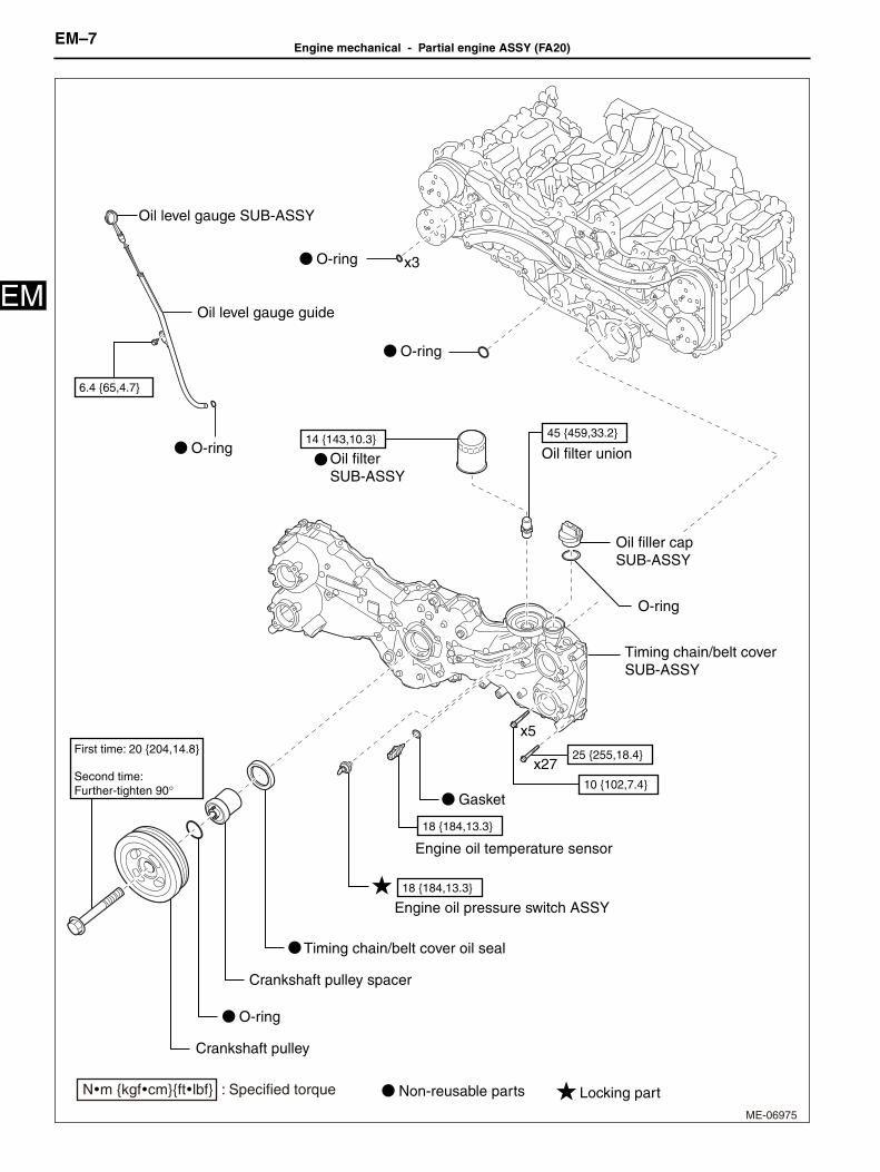
EM–7Engine mechanical - Partial engine ASSY (FA20)
EM
ME-06975
Non-reusable parts Locking part
First time: 20 {204,14.8}
Second time: Further-tighten 90°
O-ring
Crankshaft pulley spacer
Gasket
O-ring
O-ring
O-ring
x27
x5
Oil level gauge SUB-ASSY
O-ring
x3
Engine oil pressure switch ASSY
Engine oil temperature sensor
Oil filter SUB-ASSY
Oil filler cap SUB-ASSY
Oil filter union
Oil level gauge guide
Crankshaft pulley
Timing chain/belt cover SUB-ASSY
Timing chain/belt cover oil seal
18 {184,13.3}
18 {184,13.3}
25 {255,18.4}
10 {102,7.4}
45 {459,33.2}14 {143,10.3}
6.4 {65,4.7}
N�m {kgf�cm}{ft�lbf} : Specified torque

Engine mechanical - Partial engine ASSY (FA20)EM–8
M
EME-06976
x10
x2
x4
x11
x2
x2
x3
O-ring
Gasket
O-ring
Seal ring
x3
Baffle plate
Stud bolt
Drain plug
Oil strainer SUB-ASSY
Oil pan SUB-ASSY
Oil pan SUB-ASSY No. 2
Cylinder block plug
6.4 {65,4.7}
6.4 {65,4.7}
18 {184,13.3}18 {184,13.3}
6.4 {65,4.7}
90 {918,66.4}
10 {102,7.4}
42 {428,31.0}
Non-reusable parts
N�m {kgf�cm}{ft�lbf} : Specified torque

EM–9Engine mechanical - Partial engine ASSY (FA20)
EM
ME-06968
Non-reusable parts
x3
O-ring
x3
Transmission M/T:
Transmission A/T:
Cylinder head plate RR
Vacuum pump ASSY
16 {163,11.8}
16 {163,11.8}
N�m {kgf�cm}{ft�lbf} : Specified torque

Engine mechanical - Partial engine ASSY (FA20)EM–10
M
EME-06969
Chain tensioner slipper
Chain vibration damper No. 1
Chain vibration damper No. 1
Non-reusable parts
x2
x3
x2
x3
O-ring
Chain tensioner ASSY No. 2
Chain tensioner slipper
x3
x3
Camshaft timing intake gear ASSY LH
Camshaft timing intake gear ASSY RH
Camshaft timing exhaust gear ASSY LH
Camshaft timing exhaust gear ASSY RH
Crankshaft timing gear/sprocket
Chain SUB-ASSYChain SUB-ASSY
Chain tensioner ASSY No. 1
6.4 {65,4.7}6.4 {65,4.7}
6.4 {65,4.7}
6.4 {65,4.7}
18 {184,13.3}
18 {184,13.3}
18 {184,13.3}
18 {184,13.3}
N�m {kgf�cm}{ft�lbf} : Specified torque

EM–11Engine mechanical - Partial engine ASSY (FA20)
EM
ME-06974
Front camshaft cap RH
Valve rocker arm SUB-ASSY No. 1
x2
x6
x2
x2
Transmission M/T:
Transmission A/T:
Gasket
x8x2
Gasket
O-ring
Spark plug tube gasket
Cylinder head bolt
Further-tighten 50°
Seventh time: Further-tighten 100°
Sixth time: Further-tighten 100°
Fifth time: 42 {428,31.0}
First time: 20 {204,14.8}
Fourth time: 20 {204,14.8}
Third time: Loosen 360°
Second time: 100 {1020,73.8}
x12
Cylinder head cover gasket
Bank 1:
x9
x2x2
Roller rocker arm pivot
Valve adjusting shim
x8 x8x8
First time: 18 {18.4,13.3}
Third time: 18 {18.4,13.3}
Second time: Loosen 180°
x2
Intake center camshaft cap RH
Intake rear camshaft cap RHExhaust center camshaft
cap RH
Exhaust rear camshaft cap RH
Injector driver bracket
Oil control valve filter RH
Intake camshaft RH
Camshaft housing SUB-ASSY RH
Cylinder head SUB-ASSY
Cylinder head cover SUB-ASSY
Cylinder head gasket
Hole plug
Camshaft oil field pipe SUB-ASSY
Exhaust camshaft RH
Oil spacer RH
Non-reusable parts
6.4 {65,4.7}
25 {255,18.4}
31 {316,22.9}
6.4 {65,4.7}
6.4 {65,4.7}
6.4 {65,4.7}
18 {184,13.3}
N�m {kgf�cm}{ft�lbf} : Specified torque
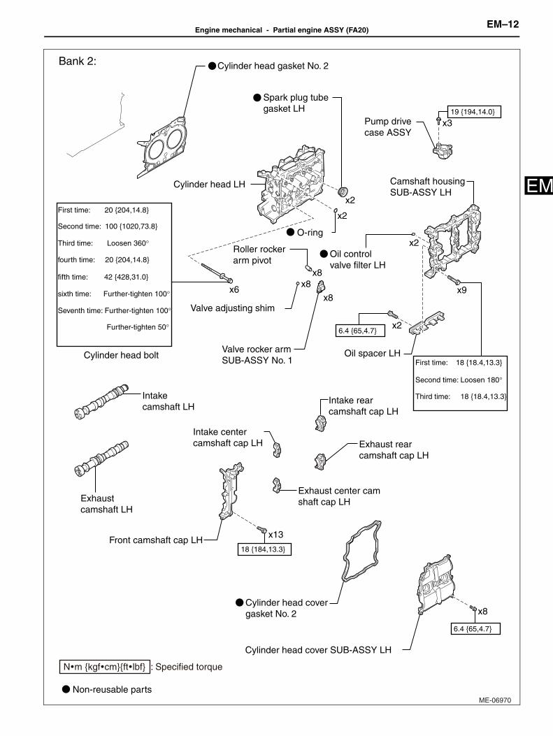
Engine mechanical - Partial engine ASSY (FA20)EM–12
M
EME-06970
x2
x9
x3
O-ring
x2
x2
Spark plug tube gasket LH
x8Cylinder head cover gasket No. 2
x6
Cylinder head bolt
Bank 2:
Valve rocker arm SUB-ASSY No. 1
x8
x8
x8
Valve adjusting shim
Roller rocker arm pivot
First time: 18 {18.4,13.3}
Third time: 18 {18.4,13.3}
Second time: Loosen 180°
Further-tighten 50°
Seventh time: Further-tighten 100°
sixth time: Further-tighten 100°
fifth time: 42 {428,31.0}
First time: 20 {204,14.8}
fourth time: 20 {204,14.8}
Third time: Loosen 360°
Second time: 100 {1020,73.8}
x2
Oil spacer LH
Oil control valve filter LH
Camshaft housing SUB-ASSY LH
Cylinder head LH
Cylinder head cover SUB-ASSY LH
Cylinder head gasket No. 2
Pump drive case ASSY
Front camshaft cap LH
Exhaust rear camshaft cap LH
Exhaust center cam shaft cap LH
x13
Intake center camshaft cap LH
Intake camshaft LH
Exhaust camshaft LH
Intake rear camshaft cap LH
6.4 {65,4.7}
6.4 {65,4.7}
18 {184,13.3}
19 {194,14.0}
Non-reusable parts
N�m {kgf�cm}{ft�lbf} : Specified torque
EM–13Engine mechanical - Partial engine ASSY (FA20)
EM
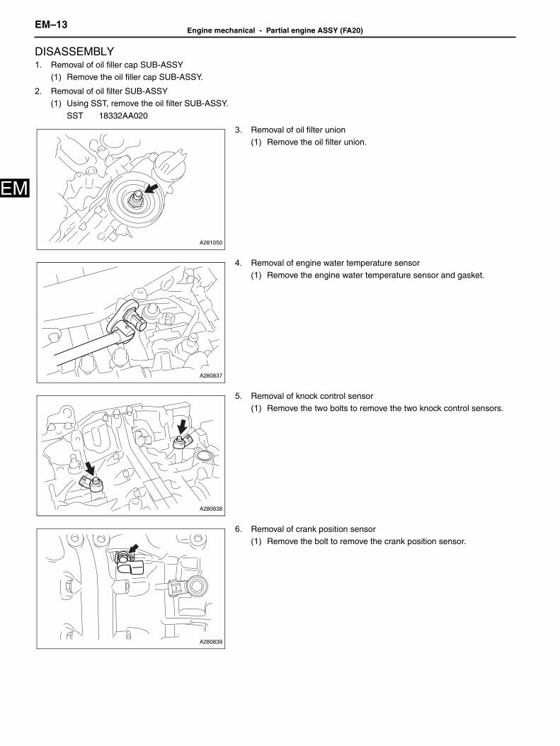
DISASSEMBLY1. Removal of oil filler cap SUB-ASSY
(1) Remove the oil filler cap SUB-ASSY.
2. Removal of oil filter SUB-ASSY(1) Using SST, remove the oil filter SUB-ASSY.
SST 18332AA020
3. Removal of oil filter union(1) Remove the oil filter union.
4. Removal of engine water temperature sensor(1) Remove the engine water temperature sensor and gasket.
5. Removal of knock control sensor(1) Remove the two bolts to remove the two knock control sensors.
6. Removal of crank position sensor(1) Remove the bolt to remove the crank position sensor.
A281050
A280837
A280838
A280839

Engine mechanical - Partial engine ASSY (FA20)EM–14
M
E7. Removal of camshaft position sensor(1) Remove the bolt to remove the camshaft position sensor (bank 1
intake side).
(2) Remove the O-ring from the camshaft position sensor.
(3) Remove the bolt to remove the camshaft position sensor (bank 1exhaust side).
(4) Remove the O-ring from the camshaft position sensor.
(5) Remove the bolt to remove the camshaft position sensor (bank 2
intake side).(6) Remove the O-ring from the camshaft position sensor.
(7) Remove the bolt to remove the camshaft position sensor (bank 2exhaust side).
(8) Remove the O-ring from the camshaft position sensor.
8. Removal of camshaft timing oil control valve ASSY(1) Remove the two bolts to remove the camshaft timing oil control
valve ASSY (bank 1 intake side).
A280840
A280841
A280842
A280843
A280844

EM–15Engine mechanical - Partial engine ASSY (FA20)
EM
(2) Remove the O-ring from the camshaft timing oil control valveASSY.Captions in illustration
(3) Remove the back-up ring from the camshaft timing oil control valveASSY.
(4) Remove the two bolts to remove the camshaft timing oil controlvalve ASSY (bank 1 exhaust side).
(5) Remove the O-ring from the camshaft timing oil control valveASSY.
(6) Remove the back-up ring from the camshaft timing oil control valve
ASSY.
(7) Remove the two bolts to remove the camshaft timing oil control
valve ASSY (bank 2 intake side).(8) Remove the O-ring from the camshaft timing oil control valve
ASSY.
(9) Remove the back-up ring from the camshaft timing oil control valveASSY.
(10)Remove the two bolts to remove the camshaft timing oil controlvalve ASSY (bank 2 exhaust side).
(11) Remove the O-ring from the camshaft timing oil control valve
ASSY.(12)Remove the back-up ring from the camshaft timing oil control valve
ASSY.
9. Removal of engine oil temperature sensor(1) Remove the engine oil temperature sensor.
<Caution>Catch the engine oil using cloth to prevent it from splashing.
A276534J01
*1 O-ring
*2 Back-up ring
A280845
A280846
A280847
A280848

Engine mechanical - Partial engine ASSY (FA20)EM–16
M
E10. Removal of engine oil pressure switch ASSY(1) Removal the engine oil pressure switch ASSY.
<Caution>Catch the engine oil using cloth to prevent it from splashing.
11. Removal of PCV hose connector(1) Remove the three bolts to remove the PCV hose connector.
(2) Slide the hose clamp to disconnect the water by-pass hose No. 1from the water inlet pipe.
(3) Slide the hose clamp to disconnect the water by-pass hose No. 1
from the PCV hose connector.
(4) Remove the two O-rings from the PCV hose connector.
12. Removal of vacuum pump ASSY (transmission A/T).
(1) Remove the three bolts to remove the vacuum pump ASSY fromthe camshaft housing SUB-ASSY.
(2) Remove the O-ring from the vacuum pump ASSY.
13. Removal of cylinder head plate RR (transmission M/T)
(1) Remove the three bolts to remove the cylinder head plate RR fromthe camshaft housing SUB-ASSY RH.
ME-06590
A280851
A279577
C260987
C260986

EM–17Engine mechanical - Partial engine ASSY (FA20)
EM
14. Removal of oil level gauge guide(1) Remove the oil level gauge SUB-ASSY.(2) Remove the bolt to remove the oil level gauge guide.
(3) Remove the O-ring from the oil level gauge guide.
15. Removal of transmission oil cooler hose No. 3 (transmission A/T)
(1) Slide the hose clamp to remove the transmission oil cooler hose No. 3.
16. Removal of water inlet pipe(1) Slide the hose clamp to remove the water by-pass hose No. 3.(2) Remove the four bolts to remove the water inlet pipe.
(3) Remove the two O-rings from cylinder block (bank 1 side and bank2 side).
17. Removal of ventilation valve SUB-ASSY(1) Remove the ventilation valve SUB-ASSY from the cylinder block
(bank 1 side).
LU-02942
A279573
A280856
A278795

Engine mechanical - Partial engine ASSY (FA20)EM–18
M
E18. Removal of pump drive case ASSY(1) Remove the three bolts to remove the pump drive case ASSY.
19. Removal of water pump pulley(1) Fix the water pump pulley using SST.
SST 18355AA000, 18334AA030
(2) Remove the three bolts to remove the water pump pulley.
20. Removal of engine water pump ASSY
(1) Remove the five bolts to remove the engine water pump ASSY andgasket.
21. Removal of water outlet
(1) Remove the two bolts to remove the water outlet.
22. Removal of thermostat
(1) Remove the thermostat.(2) Remove the gasket from the thermostat.
A278730
CO-03030
A279726
A281051

EM–19Engine mechanical - Partial engine ASSY (FA20)
EM
23. Removal of crankshaft pulley(1) Fix the crankshaft pulley using SST.
SST 18355AA000, 18334AA000
Captions in illustration
(2) Remove the crankshaft pulley set bolt to remove the crankshaftpulley.
(3) Remove the O-ring from the crankshaft pulley spacer.(4) Remove the crankshaft pulley spacer.
24. Removal of timing chain/belt cover oil seal(1) Remove the timing chain/belt cover oil seal using a flat tip
screwdriver wrapped with protective tape etc.
Captions in illustration
<Caution>Make sure that there is no flaw in the crankshaft and timing chain/beltcover oil seal fitting portion.<Reference>When flaw is found in the crankshaft, correct the crankshaft using
abrasive paper (No. 400).
25. Removal of timing chain/belt cover SUB-ASSY(1) Remove the 32 bolts.
ME-06537
*a Hold
*b Rotate
A276039
A276038J01
*1 Protective tape

Engine mechanical - Partial engine ASSY (FA20)EM–20
M
E(2) Remove the timing chain/belt cover SUB-ASSY at the rib position shown in the figure using a flat tip screwdriver wrappedwith protective tape.
Captions in illustration
<Caution>Do not damage the timing chain/belt cover SUB-ASSY, cylinder head, camshaft timing gear and cylinder block.
(3) Remove the four O-rings.
*1 Protective tape - -
ME-06633
ME-06634

EM–21Engine mechanical - Partial engine ASSY (FA20)
EM
26. Removal of the chain SUB-ASSY (bank 1 side)(1) Install the SST to the crankshaft.
SST 18252AA000
(2) Using SST and by turning the crankshaft, align the alignmentmarks of the crankshaft timing gear/sprocket, camshaft timingintake gear ASSY RH, and camshaft timing exhaust gear ASSY
RH.Captions in illustration
<Reference>
At this time, the crankshaft timing gear key points downward.
(3) Push down the chain tensioner slipper as shown in the figure, and
insert a 2.5 mm {0.098 in} dia. hex wrench into the hole of thechain tensioner ASSY No. 1 and stopper plate to secure theplunger.
A281482
A279525J01
*a Alignment mark
*b Key
A279526

Engine mechanical - Partial engine ASSY (FA20)EM–22
M
E(4) Remove the two bolts to remove the chain tensioner ASSY No. 1.
(5) Remove the chain tensioner slipper.(6) Remove the bolt, and remove the chain vibration damper No. 1.
(7) Remove the chain SUB-ASSY.<Caution>Under the condition that the chain SUB-ASSY is detached, the valve heads contact each other and valve stem may bend. Donot turn the intake camshaft RH and exhaust camshaft RH to the outside of range of zero-lift (in range where it can be turnedlightly by hand).<Reference>
Organize disassembled parts by their installation positions.
27. Removal of the chain SUB-ASSY (bank 2 side)(1) Install the SST to the crankshaft.
SST 18252AA000
(2) Using SST and by turning the crankshaft, align the alignmentmarks of the crankshaft timing gear/sprocket, camshaft timingintake gear ASSY LH, and camshaft timing exhaust gear ASSY
LH.Captions in illustration
A279527
A279528
A279529J01
*1 Key
*2 Alignment mark

EM–23Engine mechanical - Partial engine ASSY (FA20)
EM
(3) Push up the chain tensioner slipper as shown in the figure, andinsert a piece of metal wire (approx. 1 mm {0.039 in} in dia.) intothe hole of the chain tensioner ASSY No. 2 and stopper plate to
secure the plunger.
(4) Remove the two bolts to remove the chain tensioner ASSY No. 2.(5) Remove the chain tensioner slipper.
(6) Remove the O-ring from cylinder block (bank 2 side).
(7) Remove the bolt, and remove the chain vibration damper No. 1.(8) Remove the chain SUB-ASSY.
<Caution>• Under the condition that the chain SUB-ASSY is detached, the
valve heads contact each other and valve stem may bend. Do notturn the exhaust camshaft LH to the outside of range of zero-lift (inrange where it can be turned lightly by hand).
• At this time, No. 1 piston and No. 4 piston is in vicinity of TDC. Ifthe intake camshaft LH is turned, the valve and the piston maycontact and valve stem may bend. Do not turn the intake camshaftLH.
<Reference>Organize disassembled parts by their installation positions.
A279530
A279531
A279532
A279533
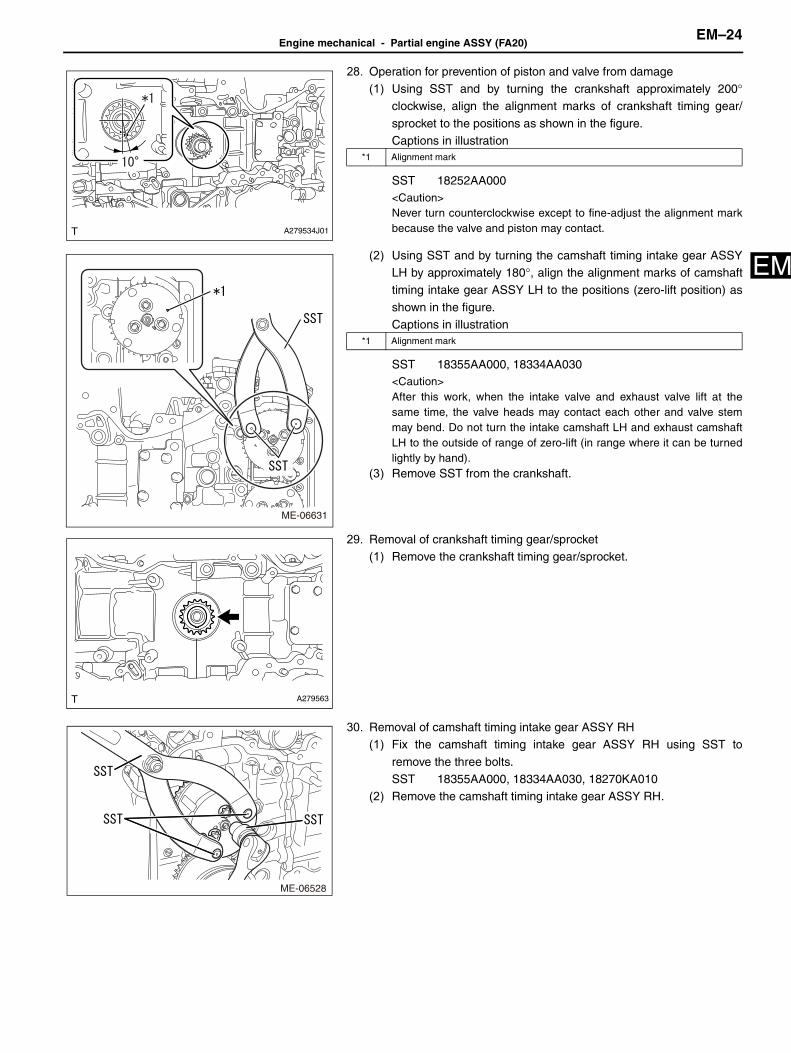
Engine mechanical - Partial engine ASSY (FA20)EM–24
M
E28. Operation for prevention of piston and valve from damage(1) Using SST and by turning the crankshaft approximately 200°
clockwise, align the alignment marks of crankshaft timing gear/
sprocket to the positions as shown in the figure.Captions in illustration
SST 18252AA000<Caution>Never turn counterclockwise except to fine-adjust the alignment markbecause the valve and piston may contact.
(2) Using SST and by turning the camshaft timing intake gear ASSYLH by approximately 180°, align the alignment marks of camshafttiming intake gear ASSY LH to the positions (zero-lift position) as
shown in the figure.Captions in illustration
SST 18355AA000, 18334AA030<Caution>After this work, when the intake valve and exhaust valve lift at thesame time, the valve heads may contact each other and valve stemmay bend. Do not turn the intake camshaft LH and exhaust camshaftLH to the outside of range of zero-lift (in range where it can be turnedlightly by hand).
(3) Remove SST from the crankshaft.
29. Removal of crankshaft timing gear/sprocket(1) Remove the crankshaft timing gear/sprocket.
30. Removal of camshaft timing intake gear ASSY RH(1) Fix the camshaft timing intake gear ASSY RH using SST to
remove the three bolts.SST 18355AA000, 18334AA030, 18270KA010
(2) Remove the camshaft timing intake gear ASSY RH.
A279534J01
*1 Alignment mark
ME-06631
*1 Alignment mark
A279563
ME-06528

EM–25Engine mechanical - Partial engine ASSY (FA20)
EM
31. Removal of camshaft timing exhaust gear ASSY RH(1) Fix the camshaft timing exhaust gear ASSY RH using SST to
remove the three bolts.
SST 18355AA000, 18334AA030, 18270KA010(2) Remove the camshaft timing exhaust gear ASSY RH.
32. Removal of camshaft timing intake gear ASSY LH
(1) Fix the camshaft timing intake gear ASSY LH using SST to removethe three bolts.SST 18355AA000, 18334AA030, 18270KA010
(2) Remove the camshaft timing intake gear ASSY LH.
33. Removal of camshaft timing exhaust gear ASSY LH(1) Fix the camshaft timing exhaust gear ASSY LH using SST to
remove the three bolts.SST 18355AA000, 18334AA030, 18270KA010
(2) Remove the camshaft timing exhaust gear ASSY LH.
34. Removal of cylinder head cover SUB-ASSY(1) Move the engine stand to face the bank 1 side upward.
(2) Remove the two bolts to remove the injector driver bracket.
(3) Remove the 8 bolts.
ME-06529
ME-06530
ME-06531
A283322
A283323

Engine mechanical - Partial engine ASSY (FA20)EM–26
M
E(4) Remove the cylinder head cover SUB-ASSY using a flat tip screwdriver wrapped with protective tape.<Caution>Do not damage the camshaft housing SUB-ASSY, cam cap and cylinder head cover SUB-ASSY.
(5) Remove the cylinder head cover gasket.(6) Remove the two spark plug tube gaskets.
<Caution>When removing the gasket using scraper, use special care not todamage the cam lobe of camshaft.
35. Removal of camshaft housing SUB-ASSY RH<Caution>Do not remove the intake and exhaust camshafts initially, because it may cause the deformation of camshaft housing SUB-ASSY.
(1) By loosening equally in the order as shown in the figure, removethe 9 bolts.
(2) Remove the camshaft housing SUB-ASSY RH using a flat tip screwdriver wrapped with protective tape.<Caution>Do not damage the cylinder head and camshaft housing SUB-ASSY.
(3) Remove the two O-rings and eight sets of valve rocker arm SUB-ASSY No. 1 from cylinder head SUB-ASSY.
<Reference>Organize disassembled parts by their installation positions.
(4) Remove the eight valve adjusting shims and eight roller rocker arm
pivots from the cylinder head SUB-ASSY.<Reference>Organize disassembled parts by their installation positions.
A283324
A283325J01
A278733
A278734

EM–27Engine mechanical - Partial engine ASSY (FA20)
EM
36. Removal of cylinder head SUB-ASSY(1) Loosen the six cylinder head bolts equally in the order as shown in
the figure.
(2) While tapping the cylinder head SUB-ASSY with a plastic hammer,separate it from cylinder block.
(3) Remove the cylinder head SUB-ASSY.<Caution>Be careful not to scratch the mating surfaces of cylinder head andcylinder block.
37. Removal of cylinder head gasket
(1) Remove the cylinder head gasket.
38. Removal of cylinder head cover SUB-ASSY LH(1) Move the engine stand to face the bank 2 side upward.
(2) Remove the 8 bolts.
(3) Remove the cylinder head cover SUB-ASSY LH using a flat tip screwdriver wrapped with protective tape.<Caution>Do not damage the camshaft housing SUB-ASSY, cam cap and cylinder head cover SUB-ASSY.
(4) Remove the cylinder head cover gasket No. 2.(5) Remove the two spark plug tube gaskets.
<Caution>When removing the gasket using scraper, use special care not todamage the cam lobe of camshaft.
39. Removal of camshaft housing SUB-ASSY LH<Caution>Do not remove the intake and exhaust camshafts initially, because it may cause the deformation of camshaft housing SUB-ASSY.
A278735J01
A279567
A279568

Engine mechanical - Partial engine ASSY (FA20)EM–28
M
E(1) By loosening equally in the order as shown in the figure, removethe 9 bolts.
(2) Remove the camshaft housing SUB-ASSY LH using a flat tip screwdriver wrapped with protective tape.<Caution>Do not damage the cylinder head and camshaft housing SUB-ASSY.
(3) Remove the two O-rings and eight sets of valve rocker arm SUB-ASSY No. 1 from cylinder head LH.
<Reference>Organize disassembled parts by their installation positions.
(4) Remove the eight valve adjusting shims and eight roller rocker arm
pivots from the cylinder head LH.<Reference>Organize disassembled parts by their installation positions.
40. Removal of cylinder head LH
(1) Loosen the six cylinder head bolts equally in the order as shown inthe figure.
(2) While tapping the cylinder head LH with a plastic hammer,
separate it from cylinder block.(3) Remove the cylinder head LH.
<Caution>Be careful not to scratch the mating surfaces of cylinder head andcylinder block.
41. Removal of cylinder head gasket No. 2(1) Remove the cylinder head gasket No. 2.
42. Removal of spark plug(1) Remove the four spark plugs.
A283326J01
A278737
A278738
ME-06503

EM–29Engine mechanical - Partial engine ASSY (FA20)
EM
43. Removal of engine hanger No. 2(1) Remove the two bolts to remove the engine hanger No. 2 from
cylinder block (bank 1 side).
44. Removal of oil pan SUB-ASSY No. 2(1) Remove the drain plug and gasket.
(2) Remove the 11 bolts.
(3) Remove the oil pan SUB-ASSY No. 2 using an oil pan seal cutter.<Caution>Do not damage the fitting surface of the oil pan SUB-ASSY and flangeportion of the oil pan SUB-ASSY No. 2.
(4) Remove the two seal rings from the oil pan SUB-ASSY No. 2.
A279574
A278797
A120816
A279593

Engine mechanical - Partial engine ASSY (FA20)EM–30
M
E45. Removal of oil strainer SUB-ASSY(1) Remove the two bolts to remove the oil strainer SUB-ASSY.(2) Remove the O-ring.
46. Removal of oil pan SUB-ASSY(1) Remove the 13 bolts.(2) Remove the oil pan SUB-ASSY using a flat tip screwdriver
wrapped with protective tape.<Caution>Do not damage the fitting surfaces of the cylinder block and oil panSUB-ASSY.
(3) Remove the three O-rings from cylinder block.
(4) Remove the four bolts to remove the oil pan baffle plate No. 1 fromthe oil pan SUB-ASSY.
(5) Remove the two stud bolts from the oil pan SUB-ASSY.
A278798
A281037
A278741
A279598
A279592

EM–31Engine mechanical - Partial engine ASSY (FA20)
EM
47. Removal of camshaft cap (bank 1 side)(1) Loosen the 12 bolts equally and slowly in order as shown in the
figure to remove the front camshaft cap RH, intake center
camshaft cap RH, intake rear camshaft cap RH, exhaust centercamshaft cap RH and exhaust rear camshaft cap RH.<Reference>
Organize disassembled parts by their installation positions.
48. Removal of camshaft (bank 1 side)(1) Remove the intake camshaft RH and exhaust camshaft RH from
the camshaft housing SUB-ASSY RH.
49. Removal of oil control valve filter RH(1) Remove the two oil control valve filters RH from the camshaft
housing SUB-ASSY RH.
50. Removal of oil spacer RH(1) Remove the two bolts to remove the oil spacer RH.
51. Removal of camshaft oil field pipe SUB-ASSY (transmission A/T)(1) Remove the two union bolts and bolt to remove the camshaft oil
field pipe SUB-ASSY and two gaskets from the camshaft housing
SUB-ASSY RH.
A278744J01
A278745
A278746
A279590
A278793

Engine mechanical - Partial engine ASSY (FA20)EM–32
M
E52. Removal of hole plug (transmission M/T).(1) Remove the hole plug and gasket from the camshaft housing SUB-
ASSY RH.
53. Removal of camshaft cap (bank 2 side)(1) Loosen the 13 bolts equally and slowly in order as shown in the
figure to remove the front camshaft cap LH, intake center camshaft
cap LH, intake rear camshaft cap LH, exhaust center camshaft capLH and exhaust rear camshaft cap LH.<Reference>
Organize disassembled parts by their installation positions.
54. Removal of camshaft (bank 2 side)(1) Remove the intake camshaft LH and exhaust camshaft LH from
the camshaft housing SUB-ASSY LH.
55. Removal of oil control valve filter LH(1) Remove the two oil control valve filters LH from the camshaft
housing SUB-ASSY LH.
56. Removal of oil spacer LH(1) Remove the two bolts to remove the oil spacer LH.
A278792
A278747J01
A278748
A278789
A279591
EM–33Engine mechanical - Partial engine ASSY (FA20)
EM
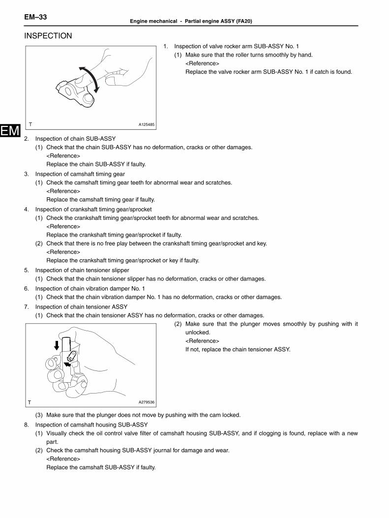
INSPECTION1. Inspection of valve rocker arm SUB-ASSY No. 1
(1) Make sure that the roller turns smoothly by hand.<Reference>Replace the valve rocker arm SUB-ASSY No. 1 if catch is found.
2. Inspection of chain SUB-ASSY
(1) Check that the chain SUB-ASSY has no deformation, cracks or other damages.<Reference>Replace the chain SUB-ASSY if faulty.
3. Inspection of camshaft timing gear
(1) Check the camshaft timing gear teeth for abnormal wear and scratches.<Reference>Replace the camshaft timing gear if faulty.
4. Inspection of crankshaft timing gear/sprocket
(1) Check the crankshaft timing gear/sprocket teeth for abnormal wear and scratches.<Reference>Replace the crankshaft timing gear/sprocket if faulty.
(2) Check that there is no free play between the crankshaft timing gear/sprocket and key.<Reference>Replace the crankshaft timing gear/sprocket or key if faulty.
5. Inspection of chain tensioner slipper
(1) Check that the chain tensioner slipper has no deformation, cracks or other damages.
6. Inspection of chain vibration damper No. 1(1) Check that the chain vibration damper No. 1 has no deformation, cracks or other damages.
7. Inspection of chain tensioner ASSY(1) Check that the chain tensioner ASSY has no deformation, cracks or other damages.
(2) Make sure that the plunger moves smoothly by pushing with itunlocked.<Reference>
If not, replace the chain tensioner ASSY.
(3) Make sure that the plunger does not move by pushing with the cam locked.
8. Inspection of camshaft housing SUB-ASSY(1) Visually check the oil control valve filter of camshaft housing SUB-ASSY, and if clogging is found, replace with a new
part.(2) Check the camshaft housing SUB-ASSY journal for damage and wear.
<Reference>
Replace the camshaft SUB-ASSY if faulty.
A125485
A279536

Engine mechanical - Partial engine ASSY (FA20)EM–34
M
E9. Inspection of camshaft(1) Check the camshaft journals for damage and wear.
<Reference>
Replace the camshaft if faulty.(2) Check the cam surface condition of camshaft.
<Reference>
• If slight fault is found, correct it using abrasive paper (No. 400).• Replace the camshaft if uneven wear is found.
(3) Runout test
(a)Set the camshaft on a V-block.(b)Using a dial gauge, check the camshaft runout.
Service limit: 0.020 mm{0.00079 in}
<Reference>• Measurement should be performed at a temperature of
20°C {68°F}.
• If it exceeds the limit, replace the camshaft.
(4) Height test
(a)Measure the height of the cam using micrometer.Standard value (intake)
Standard value (exhaust)
Standard value (fuel pump drive cam)
Captions in illustration
<Reference>• Measurement should be performed at a temperature of
20°C {68°F}.• If it is not within the specified value, replace the camshaft.
(5) Outer diameter check
(a)Check the journal outer diameter using micrometer.Standard value: 25.946 to 25.963 mm {1.02149 to 1.02216 in} <Reference>
• Measurement should be performed at a temperature of20°C {68°F}.
• If it is not within specified value, check the oil clearance.
A278753
ME-06619
Measurement location Standard value
A 40.82 to 40.92 mm {1.6083 to 1.6110 in}
B 34.0 mm {1.3386 in}
Measurement location Standard value
A 40.72 to 40.82 mm {1.6031 to 1.6071 in}
B 34.0 mm {1.3386 in}
Measurement location Standard value
C 40.55 to 40.65 mm {1.5965 to 1.6004 in}
*a Valve drive cam
*b Fuel pump drive cam
A278755

EM–35Engine mechanical - Partial engine ASSY (FA20)
EM
10. Camshaft thrust clearance check(1) Using a dial gauge, check the thrust clearance of the camshaft.
Standard value: 0.068 to 0.116 mm {0.00027 to 0.00457 in}
<Reference>• Measurement should be performed at a temperature of 20°C
{68°F}.
• Set the dial gauge at end surface of camshaft.• If it is not within the specified value or if uneven wear is found,
replace each camshaft cap and camshaft housing SUB-ASSY
as a set. If necessary replace the camshaft.
11. Camshaft oil clearance check<Reference>Measurement should be performed at a temperature of 20°C {68°F}.
(1) Remove the gasket from camshaft housing SUB-ASSY and front camshaft cap, intake rear camshaft cap and exhaustrear camshaft cap.
(2) Clean each camshaft cap and camshaft housing SUB-ASSY journal.
(3) Set the camshaft to the camshaft housing SUB-ASSY.(4) Place a plastigauge across the journals of each camshaft and set the camshaft caps.(5) Tighten each bolt in order as shown in the figure, tighten the front camshaft cap, intake center camshaft cap, intake rear
camshaft cap, exhaust center camshaft cap and exhaust rear camshaft cap.
Captions in illustration
Standard value:T=18N•m {184kgf•cm} {13.3 ft•lbf} (6) Loosen each bolt equally and slowly in order as shown in the figure to remove the bolts of the front camshaft cap, intake
center camshaft cap, intake rear camshaft cap, exhaust center camshaft cap and exhaust rear camshaft cap.
A278760
*a Bank 1 *b Bank 2
A281476J01

Engine mechanical - Partial engine ASSY (FA20)EM–36
M
ECaptions in illustration
(7) Obtain the camshaft oil clearance at the widest point of
plastigauge on each journal.Standard value: 0.037 to 0.072 mm {0.00146 to 0.00283 in} <Reference>
If it is not within the specified value, replace each camshaft capand camshaft housing SUB-ASSY as a set. If necessary replacethe camshaft.
(8) Remove the plastigauge properly.
ASSEMBLY1. Installation of oil spacer LH
(1) Install the oil spacer LH with two bolts. Standard value: T=6.4N•m {65kgf•cm} {4.7 ft•lbf}
*a Bank 1 *b Bank 2
A281476J02
A278791
A279591

EM–37Engine mechanical - Partial engine ASSY (FA20)
EM
2. Installation of oil control valve filter LH(1) Install two new oil control valve filters LH to the camshaft housing
SUB-ASSY LH.
Captions in illustration
3. Installation of camshaft (bank 2 side)(1) Apply engine oil to the camshaft housing SUB-ASSY LH journal.
(2) Install the intake camshaft LH and exhaust camshaft LH to the
camshaft housing SUB-ASSY LH.
4. Installation of camshaft cap (bank 2 side)
(1) Apply THREE BOND 1217G to the mating surface of front camshaft cap LH, intake rear camshaft cap LH and exhaustrear camshaft cap LH as shown in the figure.
Captions in illustration
A278751J01
*a0 to 0.5 mm {0 to 0.0197 in} (from the end surface of camshaft housing SUB-ASSYLH)
A278748
*1 Front camshaft cap LH *2 Intake rear camshaft cap LH
*3 Exhaust rear camshaft cap LH - -
*a 1.0 mm {0.0394 in} or less *b 3.0 to 4.0 mm {0.1181 to 0.1575 in} in dia.
*c 2.5 to 3.5 mm {0.0984 to 0.1378 in} in dia. *d 2.5 to 4.0 mm {0.0984 to 0.1575 in} in dia.
*e 1.5 to 2.5 mm {0.0591 to 0.0984 in} in dia. *f Groove
ME-06942

Engine mechanical - Partial engine ASSY (FA20)EM–38
M
E<Caution>• Clean and degrease the fitting surface.• Do not apply liquid gasket excessively to avoid engine seizure.• Do not apply liquid gasket to the intake center camshaft cap LH and exhaust center camshaft cap LH.• Install within 5 min. after applying liquid gasket.
(2) Apply engine oil to the journals of each camshaft cap and set the camshaft housing SUB-ASSY LH.(3) Tighten 13 bolts in order as shown in the figure, install the front
camshaft cap LH, intake center camshaft cap LH, intake rear
camshaft cap LH, exhaust center camshaft cap LH and exhaustrear camshaft cap LH. Standard value: T=18N•m {184kgf•cm} {13.3 ft•lbf}
5. Installation of hole plug (transmission M/T)(1) Using a new gasket, install the hole plug to the camshaft housing
SUB-ASSY RH. Standard value: T=25N•m {225kgf•cm} {18.4 ft•lbf}
6. Installation of camshaft oil field pipe SUB-ASSY (transmission A/T)(1) Using two new gaskets, temporarily tighten the camshaft oil field pipe SUB-ASSY with the two union bolts and bolt.
(2) Tighten the two union bolts to specified torque. Standard value: T=31N•m {316kgf•cm} {22.9 ft•lbf}
(3) Tighten the bolt to specified torque. Standard value: T=6.4N•m {65kgf•cm} {4.7 ft•lbf}
A278747J02
A278792
A278793

EM–39Engine mechanical - Partial engine ASSY (FA20)
EM
7. Installation of oil spacer RH(1) Install the oil spacer RH with two bolts.
Standard value: T=6.4N•m {65kgf•cm} {4.7 ft•lbf}
8. Installation of oil control valve filter RH(1) Install two new oil control valve filters RH to the camshaft housing
SUB-ASSY RH as shown in the figure.
Captions in illustration
9. Installation of camshaft (bank 1 side)(1) Apply engine oil to the camshaft housing SUB-ASSY RH journal.
(2) Install the intake camshaft RH and exhaust camshaft RH to the
camshaft housing SUB-ASSY RH.
10. Installation of camshaft cap (bank 1 side)
(1) Apply THREE BOND 1217G to the mating surface of front camshaft cap RH, intake rear camshaft cap RH and exhaustrear camshaft cap RH as shown in the figure.
A279590
A278749J01
*a0 to 0.5 mm {0 to 0.0197 in} (from the end surface of camshaft housing SUB-ASSYRH)
A278745

Engine mechanical - Partial engine ASSY (FA20)EM–40
M
ECaptions in illustration
<Caution>• Clean and degrease the fitting surface.• Do not apply liquid gasket excessively to avoid engine seizure.• Do not apply liquid gasket to the intake center camshaft cap RH and exhaust center camshaft cap RH.• Install within 5 min. after applying liquid gasket.
(2) Apply engine oil to the journals of each camshaft cap and set to the camshaft housing SUB-ASSY RH.(3) Tighten 12 bolts in order as shown in the figure, install the front
camshaft cap RH, intake center camshaft cap RH, intake rearcamshaft cap RH, exhaust center camshaft cap RH and exhaustrear camshaft cap RH.
Standard value: T=18N•m {184kgf•cm} {13.3 ft•lbf}
*1 Front camshaft cap RH *2 Intake rear camshaft cap RH
*3 Exhaust rear camshaft cap RH - -
*a 2.5 to 4.0 mm {0.0984 to 0.1575 in} in diameter *b 1.0 mm {0.0394 in} or less
*c 3.0 to 4.0 mm {0.1181 to 0.1575 in} in diameter *d 1.5 to 2.5 mm {0.0591 to 0.0984 in} in diameter
*e Groove - -
ME-06943
A278744J02

EM–41Engine mechanical - Partial engine ASSY (FA20)
EM
11. Installation of oil pan SUB-ASSY(1) Install the two stud bolts to the oil pan SUB-ASSY.
Standard value: T=10N•m {102kgf•cm} {7.4 ft•lbf}
Stud bolt height (A): 70.0 mm {2.756 in}
(2) Install the baffle plate No. 1 to the oil pan SUB-ASSY with four
bolts. Standard value: T=6.4N•m {65kgf•cm} {4.7 ft•lbf}
(3) Apply THREE BOND 1217G to the mating surface of the oil panSUB-ASSY as shown in the figure.Captions in illustration
<Caution>• Clean and degrease the fitting surface.• Install within 5 min. after applying liquid gasket.• Apply liquid gasket 1.5 mm {0.0591 in} outside from the groove of
the oil pan SUB-ASSY.However, application of liquid gasket aroundthe bolt hole is allowed.
(4) Install three new O-rings to the cylinder block.
A280854J01
A279598
ME-06961
*a THREE BOND 1217G
*b 4.0 to 6.0 mm {0.158 to 0.236 in} in diameter
*c Groove
A278741

Engine mechanical - Partial engine ASSY (FA20)EM–42
M
E(5) Tighten 13 bolts (A and B) in order as shown in the figure, andinstall the oil pan SUB-ASSY to the cylinder block. Standard value: T=18N•m {184kgf•cm} {13.3 ft•lbf}
Captions in illustration
<Reference>After tightening, if the liquid gasket is squeezed out in the seal
surface area of the timing chain/belt cover SUB-ASSY, completelyremove any liquid gasket that is squeezed out.
12. Installation of oil strainer SUB-ASSY(1) Install a new O-ring.
(2) Install the oil strainer SUB-ASSY to the oil pan SUB-ASSY withtwo bolts. Standard value: T=6.4N•m {65kgf•cm} {4.7 ft•lbf}
13. Installation of oil pan SUB-ASSY No. 2(1) Install the two new oil pan seal rings to the oil pan SUB-ASSY No.
2.
A279588J03
Bolt A
Bolt B
Bolt type Bolt length (except for head)
Bolt A 25 mm {0.984 in}
Bolt B 75 mm {2.953 in}
A278798
A279593J01

EM–43Engine mechanical - Partial engine ASSY (FA20)
EM
(2) Apply THREE BOND 1217G to the mating surface of the oil panSUB-ASSY No. 2 of the oil pan SUB-ASSY as shown in the figure.Captions in illustration
<Caution>• Clean and degrease the fitting surface.• Install within 5 min. after applying liquid gasket.
(3) Tighten 11 bolts in order as shown in the figure, and install the oilpan SUB-ASSY No. 2.
Standard value: T=6.4N•m {65kgf•cm} {4.7 ft•lbf}
14. Installation of engine hanger No. 2(1) Install the engine hanger No. 2 to the cylinder block (bank 1 side)
with two bolts. Standard value: T=21N•m {214kgf•cm} {15.5 ft•lbf}
15. Installation of cylinder head gasket No. 2(1) Move the engine stand to face the bank 2 side upward.
(2) Clean the bolt holes in the cylinder block (bank 2 side).<Caution>To avoid erroneous tightening of the bolts, clean out the bolt holes sufficiently by blowing with compressed air to eliminateengine coolant etc.
(3) Apply THREE BOND 1217G to the mating surface of the new cylinder head gasket No. 2 as shown in the figure.
ME-06962
*a THREE BOND 1217G
*b 4.0 to 6.0 mm {0.158 to 0.236 in} in diameter
A278797J01
A279574

Engine mechanical - Partial engine ASSY (FA20)EM–44
M
ECaptions in illustration<Caution>• Clean and degrease the fitting surface.• Install within 5 min. after applying liquid gasket.
(4) Install the cylinder head gasket No. 2.
16. Installation of cylinder head LH(1) Clean the cylinder head bolt threads and apply sufficient engine oil to the washer and cylinder head bolt threads.(2) Set the cylinder head LH to the cylinder block (bank 2 side).
(3) Tighten the six cylinder head bolts in the order as shown in thefigure. Standard value: T=20N•m {204kgf•cm} {14.8 ft•lbf}
(4) Further-tighten the six cylinder head bolts in the same order. Standard value: T=100N•m {102kgf•cm} {73.8 ft•lbf}<Caution>If the bolt makes stick-slip sound during tightening, clean the bolt holes and the fitting surface and wait until it dries, and thenrepeat the process from the procedure of application of gasket.<Reference>If the processes are resumed, the cylinder head gasket can be reused.
(5) Loosen the six cylinder head bolts by 360° in the order as shown inthe figure.
*a 0 to 1.0 mm {0 to 0.039 in} *b 2.0 to 4.0 mm {0.079 to 0.158 in} in diameter
*c Gasket end - -
A278764J02
ME-06502
ME-06503

EM–45Engine mechanical - Partial engine ASSY (FA20)
EM
(6) Tighten the six cylinder head bolts in the order as shown in thefigure. Standard value: T=20N•m {204kgf•cm} {14.8 ft•lbf}
(7) Further-tighten the six cylinder head bolts in the same order. Standard value: T=42N•m {428kgf•cm} {31.0 ft•lbf}
(8) Further-tighten the six cylinder head bolts by 100° in the order as
shown in the figure using SST.SST 18854AA000Captions in illustration
<Reference>
As necessary, attach the temporary bolt to fix SST.
(9) Further-tighten the two cylinder head bolts by 100° in the order as
shown in the figure using SST.SST 18854AA000
(10)Further-tighten the four cylinder head bolts by 50° in the order asshown in the figure using SST.SST 18854AA000
17. Installation of camshaft housing SUB-ASSY LH(1) Apply engine oil to the valve adjusting shim and the roller rocker
arm pivot, and install to the cylinder head LH.
ME-06502
ME-06505
*a Temporary bolt
ME-06641
ME-06506
A278738
Engine mechanical - Partial engine ASSY (FA20)EM–46
M
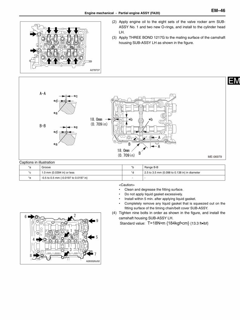
E(2) Apply engine oil to the eight sets of the valve rocker arm SUB-ASSY No. 1 and two new O-rings, and install to the cylinder headLH.
(3) Apply THREE BOND 1217G to the mating surface of the camshafthousing SUB-ASSY LH as shown in the figure.
Captions in illustration
<Caution>• Clean and degrease the fitting surface.• Do not apply liquid gasket excessively.• Install within 5 min. after applying liquid gasket.• Completely remove any liquid gasket that is squeezed out on the
fitting surface of the timing chain/belt cover SUB-ASSY.(4) Tighten nine bolts in order as shown in the figure, and install the
camshaft housing SUB-ASSY LH. Standard value: T=18N•m {184kgf•cm} {13.3 ft•lbf}
A278737
*a Groove *b Range B-B
*c 1.0 mm {0.0394 in} or less *d 2.5 to 3.5 mm {0.098 to 0.138 in} in diameter
*e -0.5 to 0.5 mm {-0.0197 to 0.0197 in} - -
ME-06979
A283326J02

EM–47Engine mechanical - Partial engine ASSY (FA20)
EM
<Reference>Set the intake camshaft LH and the exhaust camshaft LH to thezero-lift position.
(5) Loosen the three bolts by 180° in the order as shown in the figure.
(6) Tighten the three bolts in the order as shown in the figure.
Standard value: T=18N•m {184kgf•cm} {13.3 ft•lbf}
(7) Loosen the three bolts by 180° in the order as shown in the figure.
(8) Tighten the three bolts in the order as shown in the figure. Standard value: T=18N•m {184kgf•cm} {13.3 ft•lbf}
A278759
A283328J01
A283328J02
A283328J03
A283328J04

Engine mechanical - Partial engine ASSY (FA20)EM–48
M
E(9) Loosen the three bolts by 180° in the order as shown in the figure.
(10)Tighten the three bolts in the order as shown in the figure. Standard value: T=18N•m {184kgf•cm} {13.3 ft•lbf}
<Reference>After tightening, if the liquid gasket is squeezed out in the sealsurface area of the timing chain/belt cover SUB-ASSY, completely
remove any liquid gasket that is squeezed out.
18. Valve clearance check (bank 2 side)<Caution>Under the condition that the chain SUB-ASSY (bank 2 side) is detached, the valve heads contact each other and valve stem maybend. Do not turn the intake camshaft LH and exhaust camshaft LH to the outside of range of zero-lift (in range where it can beturned lightly by hand).(1) Measure the roller surface of cam base circle and valve rocker arm SUB-ASSY No.1 using thickness gauge.
Standard value (when cold): 0.10 to 0.16 mm {0.0039 to 0.0063 in} (intake side)
0.21 to 0.27 mm {0.0083 to 0.0106 in} (exhaust side)<Reference>• For valve clearance inspection, adjust the cam base circle position so that the thickness gauge can be inserted easily
by hand turning the camshaft to be measured.• If the measured value is out of standard, take notes of the value in order to adjust the valve clearance later on.
19. Valve clearance adjustment (bank 2 side)(1) Remove the camshaft housing SUB-ASSY LH.
(2) Remove the valve rocker arm SUB-ASSY No. 1.(3) Remove the valve adjusting shim.
A283328J05
A283328J06
A281473

EM–49Engine mechanical - Partial engine ASSY (FA20)
EM
(4) Measure the thickness of the removed valve adjusting shim usingmicrometer.
(5) Calculate the thickness of the valve adjusting shim so that the valve clearance is within the specified range.Standard value: Intake side: (Selected shim thickness) = (removed shim thickness) + [(measured clearance) -
0.13 mm {0.0051 in}] × 1.54Exhaust side: (Selected shim thickness) = (removed shim thickness) + [(measured clearance) -0.24 mm {0.0094 in}] × 1.69
(6) Apply engine oil to the inner circle area of the selected valve adjusting shim, and install to the valve.<Caution>Make sure that the valve adjusting shim turns smoothly after inserting.
(7) Install the valve rocker arm SUB-ASSY No. 1.(8) Install the camshaft housing SUB-ASSY LH.
20. Installation of cylinder head cover SUB-ASSY LH(1) Apply a light coat of engine oil to the two new spark plug tube
gaskets, and insert them up to the spark plug tube end.Captions in illustration
(2) Install the new cylinder head cover gasket No. 2 to the cylinderhead cover SUB-ASSY LH.
(3) Apply THREE BOND 1217G to the mating surface of the cylinder
head cover SUB-ASSY LH as shown in the figure.
Captions in illustration
A281710
A279571J01
*a Spark plug tube end
A279572J02
Application area Application length
A 10.0 mm {0.394 in} or more
B 18.8 mm {0.740 in} or more
C 63.0 mm {2.480 in} or more
*a Arch starting point
*b 2.0 to 4.0 mm {0.079 to 0.158 in} in diameter

Engine mechanical - Partial engine ASSY (FA20)EM–50
M
E(4) Set the cylinder head cover SUB-ASSY LH, and tighten the eightbolts in the order as shown in the figure. Standard value: T=6.4N•m {65kgf•cm} {4.7 ft•lbf}
21. Installation of cylinder head gasket
(1) Move the engine stand to face the bank 1 side upward.(2) Clean the bolt holes in the cylinder block (bank 1 side).
<Caution>To avoid erroneous tightening of the bolts, clean out the bolt holes sufficiently by blowing with compressed air to eliminateengine coolant etc.
(3) Apply THREE BOND 1217G to the both surfaces of the cylinder head gasket as shown in the figure.
Captions in illustration
<Caution>• Clean and degrease the fitting surface.• Install within 5 min. after applying liquid gasket.
(4) Attach the cylinder head gasket.
22. Installation of cylinder head SUB-ASSY
(1) Clean the cylinder head bolt threads and apply sufficient engine oil to the washer and cylinder head bolt threads.(2) Set the cylinder head SUB-ASSY to the cylinder block (bank 1 side).
(3) Tighten the six cylinder head bolts in the order as shown in the
figure. Standard value: T=20N•m {204kgf•cm} {14.8 ft•lbf}
(4) Further-tighten the six cylinder head bolts in the same order. Standard value: T=100N•m {102kgf•cm} {73.8 ft•lbf}
ME-06507
*a 0 to 1.0 mm {0 to 0.039 in} *b 2.0 to 4.0 mm {0.79 to 0.158 in} in diameter
*c Gasket end - -
A278761J02
A278735J02

EM–51Engine mechanical - Partial engine ASSY (FA20)
EM
<Caution>If the bolt makes stick-slip sound during tightening, clean the bolt holes and the fitting surface and wait until it dries, and thenrepeat the process from the procedure of application of gasket.<Reference>If the processes are resumed, the cylinder head gasket can be reused.
(5) Loosen the six cylinder head bolts by 360° in the order as shown inthe figure.
(6) Tighten the six cylinder head bolts in the order as shown in thefigure.
Standard value: T=20N•m {204kgf•cm} {14.8 ft•lbf}
(7) Further-tighten the six cylinder head bolts in the same order.
Standard value: T=42N•m {428kgf•cm} {31.0 ft•lbf}
(8) Further-tighten the six cylinder head bolts by 100° in the order as
shown in the figure using SST.SST 18854AA000Captions in illustration
<Reference>
As necessary, attach the temporary bolt to fix SST.
(9) Further-tighten the two cylinder head bolts by 100° in the order asshown in the figure using SST.SST 18854AA000
A278735J01
A278735J02
ME-06642
*a Temporary bolt
ME-06643

Engine mechanical - Partial engine ASSY (FA20)EM–52
M
E(10)Further-tighten the four cylinder head bolts by 50° in the order asshown in the figure using SST.SST 18854AA000
23. Installation of camshaft housing SUB-ASSY RH(1) Apply engine oil to the valve adjusting shim and the roller rocker
arm pivot, and install to the cylinder head SUB-ASSY.
(2) Apply engine oil to the eight sets of the valve rocker arm SUB-ASSY No. 1 and two new O-rings, and install to the cylinder head
SUB-ASSY.(3) Apply THREE BOND 1217G to the mating surface of the camshaft
housing SUB-ASSY RH as shown in the figure.
Captions in illustration
ME-06644
A278734
A278733
*a Range B-B *b 0 to 1.0 mm {0 to 0.0394 in}
*c 2.5 to 3.5 mm {0.098 to 0.138 in} in diameter *d -0.5 to 0.5 mm {-0.0197 to 0.0197 in}
*e Groove end - -
ME-06980
EM–53Engine mechanical - Partial engine ASSY (FA20)
EM
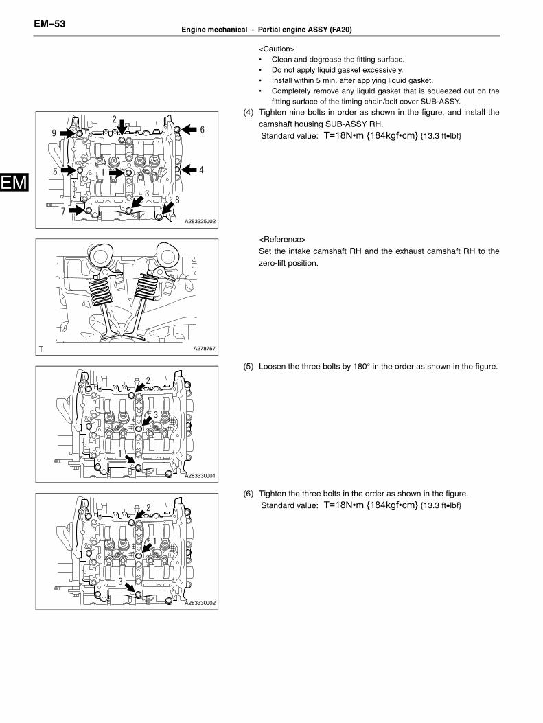
<Caution>• Clean and degrease the fitting surface.• Do not apply liquid gasket excessively.• Install within 5 min. after applying liquid gasket.• Completely remove any liquid gasket that is squeezed out on the
fitting surface of the timing chain/belt cover SUB-ASSY.(4) Tighten nine bolts in order as shown in the figure, and install the
camshaft housing SUB-ASSY RH. Standard value: T=18N•m {184kgf•cm} {13.3 ft•lbf}
<Reference>Set the intake camshaft RH and the exhaust camshaft RH to the
zero-lift position.
(5) Loosen the three bolts by 180° in the order as shown in the figure.
(6) Tighten the three bolts in the order as shown in the figure. Standard value: T=18N•m {184kgf•cm} {13.3 ft•lbf}
A283325J02
A278757
A283330J01
A283330J02
Engine mechanical - Partial engine ASSY (FA20)EM–54
M
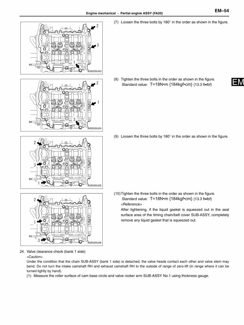
E(7) Loosen the three bolts by 180° in the order as shown in the figure.
(8) Tighten the three bolts in the order as shown in the figure. Standard value: T=18N•m {184kgf•cm} {13.3 ft•lbf}
(9) Loosen the three bolts by 180° in the order as shown in the figure.
(10)Tighten the three bolts in the order as shown in the figure. Standard value: T=18N•m {184kgf•cm} {13.3 ft•lbf}<Reference>
After tightening, if the liquid gasket is squeezed out in the sealsurface area of the timing chain/belt cover SUB-ASSY, completelyremove any liquid gasket that is squeezed out.
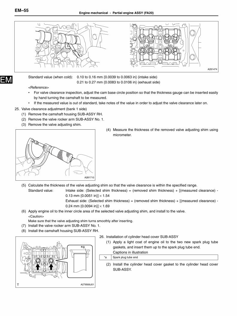
24. Valve clearance check (bank 1 side)<Caution>Under the condition that the chain SUB-ASSY (bank 1 side) is detached, the valve heads contact each other and valve stem maybend. Do not turn the intake camshaft RH and exhaust camshaft RH to the outside of range of zero-lift (in range where it can beturned lightly by hand).(1) Measure the roller surface of cam base circle and valve rocker arm SUB-ASSY No.1 using thickness gauge.
A283330J03
A283330J04
A283330J05
A283330J06
EM–55Engine mechanical - Partial engine ASSY (FA20)
EM
Standard value (when cold): 0.10 to 0.16 mm {0.0039 to 0.0063 in} (intake side)0.21 to 0.27 mm {0.0083 to 0.0106 in} (exhaust side)<Reference>• For valve clearance inspection, adjust the cam base circle position so that the thickness gauge can be inserted easily
by hand turning the camshaft to be measured.
• If the measured value is out of standard, take notes of the value in order to adjust the valve clearance later on.
25. Valve clearance adjustment (bank 1 side)(1) Remove the camshaft housing SUB-ASSY RH.(2) Remove the valve rocker arm SUB-ASSY No. 1.
(3) Remove the valve adjusting shim.(4) Measure the thickness of the removed valve adjusting shim using
micrometer.
(5) Calculate the thickness of the valve adjusting shim so that the valve clearance is within the specified range.
Standard value: Intake side: (Selected shim thickness) = (removed shim thickness) + [(measured clearance) -0.13 mm {0.0051 in}] × 1.54Exhaust side: (Selected shim thickness) = (removed shim thickness) + [(measured clearance) -
0.24 mm {0.0094 in}] × 1.69(6) Apply engine oil to the inner circle area of the selected valve adjusting shim, and install to the valve.
<Caution>Make sure that the valve adjusting shim turns smoothly after inserting.
(7) Install the valve rocker arm SUB-ASSY No. 1.(8) Install the camshaft housing SUB-ASSY RH.
26. Installation of cylinder head cover SUB-ASSY
(1) Apply a light coat of engine oil to the two new spark plug tubegaskets, and insert them up to the spark plug tube end.Captions in illustration
(2) Install the cylinder head cover gasket to the cylinder head cover
SUB-ASSY.
A281474
A281710
A279569J01
*a Spark plug tube end

Engine mechanical - Partial engine ASSY (FA20)EM–56
M
E(3) Apply THREE BOND 1217G to the mating surface of the cylinderhead cover SUB-ASSY as shown in the figure.
Captions in illustration
(4) Set the cylinder head cover SUB-ASSY, and tighten the eight boltsin the order as shown in the figure. Standard value: T=6.4N•m {65kgf•cm} {4.7 ft•lbf}
(5) Install the injector driver bracket using two bolts. Standard value: T=6.4N•m {65kgf•cm} {4.7 ft•lbf}
27. Installation of spark plug(1) Install the four spark plugs.
Standard value: T=17N•m {173kgf•cm} {12.5 ft•lbf}
28. Installation of camshaft timing exhaust gear ASSY LH<Caution>Before installation, check that there is no foreign matter on the camshaft timing exhaust gear ASSY LH and exhaust camshaft LH.
A279570J01
Application area Application length
A 10.0 mm {0.394 in} or more
B 68.0 mm {2.677 in} or more
C 70.7 mm {2.784 in} or more
*a Arch starting point
*b 2.0 to 4.0 mm {0.079 to 0.158 in} in diameter
A283323J01
A283322

EM–57Engine mechanical - Partial engine ASSY (FA20)
EM
(1) Install the camshaft timing exhaust gear ASSY LH by aligning theknock hole of the camshaft timing exhaust gear ASSY LH and theknock pin of the exhaust camshaft LH.
Captions in illustration
(2) Fix the camshaft timing exhaust gear ASSY LH using SST and
tighten the three bolts.SST 18355AA000, 18334AA030, 18270KA010 Standard value: T=18N•m {184kgf•cm} {13.3 ft•lbf}
29. Installation of camshaft timing intake gear ASSY LH<Caution>Before installation, check that there is no foreign matter on the camshaft timing intake gear ASSY LH and intake camshaft LH.
(1) Install the camshaft timing intake gear ASSY LH by aligning theknock hole of the camshaft timing intake gear ASSY LH and the
knock pin of the intake camshaft LH.Captions in illustration
(2) Fix the camshaft timing intake gear ASSY LH using SST andtighten the three bolts.SST 18355AA000, 18334AA030, 18270KA010
Standard value: T=18N•m {184kgf•cm} {13.3 ft•lbf}
30. Installation of camshaft timing exhaust gear ASSY RH<Caution>Before installation, check that there is no foreign matter on the camshaft timing exhaust gear ASSY RH and exhaust camshaft RH.
A279561J01
*1 Knock hole
*2 Knock pin
ME-06532
A279559J01
*1 Knock hole
*2 Knock pin
ME-06533

Engine mechanical - Partial engine ASSY (FA20)EM–58
M
E(1) Install the camshaft timing exhaust gear ASSY RH by aligning theknock hole of the camshaft timing exhaust gear ASSY RH and theknock pin of the exhaust camshaft RH.
Captions in illustration
(2) Fix the camshaft timing exhaust gear ASSY RH using SST and
tighten the three bolts.SST 18355AA000, 18334AA030, 18270KA010 Standard value: T=18N•m {184kgf•cm} {13.3 ft•lbf}
31. Installation of camshaft timing intake gear ASSY RH<Caution>Before installation, check that there is no foreign matter on the camshaft timing intake gear ASSY RH and intake camshaft RH.
(1) Install the camshaft timing intake gear ASSY RH by aligning theknock hole of the camshaft timing intake gear ASSY RH and the
knock pin of the intake camshaft RH.Captions in illustration
(2) Fix the camshaft timing intake gear ASSY RH using SST andtighten the three bolts.SST 18355AA000, 18334AA030, 18270KA010
Standard value: T=18N•m {184kgf•cm} {13.3 ft•lbf}
A279557J01
*1 Knock hole
*2 Knock pin
ME-06534
A279555J01
*1 Knock hole
*2 Knock pin
ME-06535

EM–59Engine mechanical - Partial engine ASSY (FA20)
EM
32. Installation of crankshaft timing gear/sprocket(1) Install the crankshaft timing gear/sprocket.
33. Installation of chain SUB-ASSY (bank 2 side)<Caution>Be careful that the foreign matter is not into or onto the assembled component during installation.<Reference>Apply engine oil to all component parts of the chain SUB-ASSY.(1) Install the SST to the crankshaft.
SST 18252AA000(2) Move the link plate in the direction of arrow to press in the plunger.
Captions in illustration
(3) Insert a piece of metal wire (approx. 1 mm {0.0394 in} dia.) into thestopper pin hole to secure the plunger.<Reference>
If the stopper pin hole on the link plate and the stopper pin hole onthe chain tensioner ASSY are not aligned, check that the firstnotch of plunger rack is engaged with the stopper tooth.If not
engaged, retract the plunger a little so that the first notch ofplunger rack is engaged with the stopper tooth.Captions in illustration
(4) Check that the crankshaft timing gear/sprocket is located at theposition shown in the figure. If not aligned, turn the crankshaft toalign the crankshaft timing gear/sprocket alignment mark to the
position shown in the figure.Captions in illustration
<Caution>Perform properly to avoid contact of the valve and piston.
A279563
A279536J01
*1 Link plate
*2 Plunger
A279537J01 *1 First notch of rack
*2 Stopper tooth
A279534J02
*1 Alignment mark

Engine mechanical - Partial engine ASSY (FA20)EM–60
M
E(5) Using SST and by turning the camshaft timing intake gear ASSYLH, align the alignment mark to the position as shown in the figure.SST 18355AA000, 18334AA030<Caution>The intake valve and exhaust valve contact each other and valve stemmay bend. Do not turn the exhaust camshaft LH.Captions in illustration
(6) Using SST and by turning the crankshaft approximately 200°counterclockwise, align the crankshaft timing gear key to theposition as shown in the figure.
SST 18252AA000<Caution>Never turn clockwise because the valve and piston may contact.However, turning clockwise is allowed in case of fine adjustment afteraligning the crankshaft timing gear key to the position shown in thefigure.Captions in illustration
(7) Remove SST.
(8) Using SST and by turning the camshaft timing exhaust gear ASSYLH, align the alignment mark to the position as shown in the figure.SST 18355AA000, 18334AA030<Caution>To prevent valve damage, turn the camshaft timing exhaust gear ASSYLH only within the range of zero-lift (in range where it can be turnedlightly by hand).Captions in illustration
ME-06591
*1 Alignment mark
ME-06549 *1 Key
A279540J01
*1 Alignment mark

EM–61Engine mechanical - Partial engine ASSY (FA20)
EM
(9) Align the mark plate (blue) of the chain SUB-ASSY to thealignment mark of the crankshaft timing gear/sprocket.Captions in illustration
(10)Align the mark plate (pink) of the chain SUB-ASSY to the timing mark of the camshaft timing intake gear ASSY LH.(11) Align the mark (pink) of the chain SUB-ASSY to the timing mark of the camshaft timing exhaust gear ASSY LH.(12)Apply engine oil to the sliding surface of the chain vibration damper No. 1 bolt.
(13) Install the chain vibration damper No. 1 with the bolt. Standard value: T=6.4N•m {65kgf•cm} {4.7 ft•lbf}
(14) Install a new O-ring to the cylinder block (bank 2 side).
(15) Install the chain tensioner slipper.
(16)Tighten the two bolts to install the chain tensioner ASSY No. 2. Standard value: T=6.4N•m {65kgf•cm} {4.7 ft•lbf}
A279541J02
*a Alignment mark
*b Timing mark
*c Mark plate (blue)
*d Mark plate (pink)
A279532
A279531
Engine mechanical - Partial engine ASSY (FA20)EM–62
M
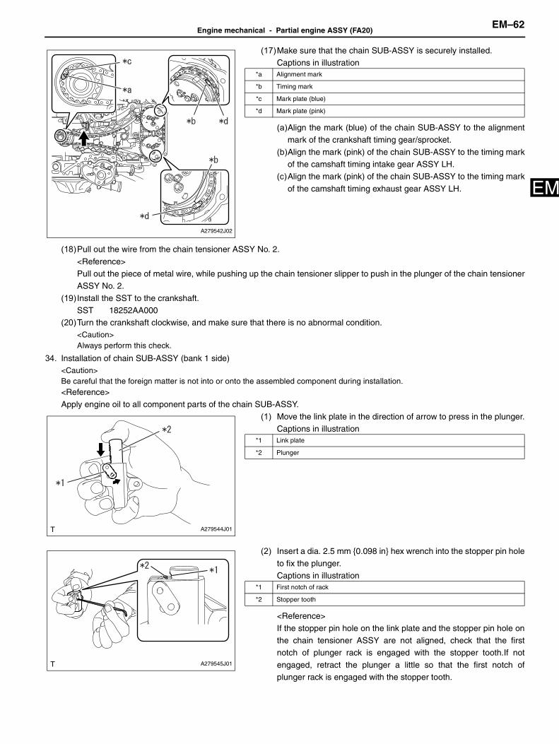
E(17)Make sure that the chain SUB-ASSY is securely installed.Captions in illustration
(a)Align the mark (blue) of the chain SUB-ASSY to the alignmentmark of the crankshaft timing gear/sprocket.
(b)Align the mark (pink) of the chain SUB-ASSY to the timing markof the camshaft timing intake gear ASSY LH.
(c)Align the mark (pink) of the chain SUB-ASSY to the timing mark
of the camshaft timing exhaust gear ASSY LH.
(18)Pull out the wire from the chain tensioner ASSY No. 2.
<Reference>Pull out the piece of metal wire, while pushing up the chain tensioner slipper to push in the plunger of the chain tensionerASSY No. 2.
(19) Install the SST to the crankshaft.SST 18252AA000
(20)Turn the crankshaft clockwise, and make sure that there is no abnormal condition.<Caution>Always perform this check.
34. Installation of chain SUB-ASSY (bank 1 side)<Caution>Be careful that the foreign matter is not into or onto the assembled component during installation.<Reference>Apply engine oil to all component parts of the chain SUB-ASSY.
(1) Move the link plate in the direction of arrow to press in the plunger.Captions in illustration
(2) Insert a dia. 2.5 mm {0.098 in} hex wrench into the stopper pin hole
to fix the plunger.Captions in illustration
<Reference>
If the stopper pin hole on the link plate and the stopper pin hole onthe chain tensioner ASSY are not aligned, check that the firstnotch of plunger rack is engaged with the stopper tooth.If not
engaged, retract the plunger a little so that the first notch ofplunger rack is engaged with the stopper tooth.
A279542J02
*a Alignment mark
*b Timing mark
*c Mark plate (blue)
*d Mark plate (pink)
A279544J01
*1 Link plate
*2 Plunger
A279545J01
*1 First notch of rack
*2 Stopper tooth

EM–63Engine mechanical - Partial engine ASSY (FA20)
EM
(3) Using SST and by turning the crankshaft, align the alignment markof the crankshaft timing gear/sprocket, camshaft timing intake gearASSY LH and camshaft timing exhaust gear ASSY LH.
Captions in illustration
<Reference>When the mark is aligned to the position shown in the figure, thecrankshaft timing gear key points downward.
(4) Using SST, align the alignment mark of the camshaft timing intake
gear ASSY RH and camshaft timing exhaust gear ASSY RH to theposition as shown in the figure.SST 18355AA000, 18334AA030<Caution>To prevent valve damage, turn the camshaft timing intake gear ASSYRH and camshaft timing exhaust gear ASSY RH only within the rangeof zero-lift (in range where it can be turned lightly by hand).Captions in illustration
(5) Align the mark plate (blue) of the chain SUB-ASSY to thealignment mark of the crankshaft timing gear/sprocket.
Captions in illustration
(6) Align the mark plate (pink) of the chain SUB-ASSY to the timing mark of the camshaft timing intake gear ASSY RH.(7) Align the mark plate (pink) of the chain SUB-ASSY to the timing mark of the camshaft timing exhaust gear ASSY RH.
(8) Apply engine oil to the sliding surface of the chain vibration damper No. 1 bolt.(9) Install the chain vibration damper No. 1 with the bolt.
Standard value: T=6.4N•m {65kgf•cm} {4.7 ft•lbf}
A279546J02
*1 Alignment mark
A279547J02
*1 Alignment mark
A279548J01
*a Alignment mark
*b Timing mark
*c Mark plate (blue)
*d Mark plate (pink)
Engine mechanical - Partial engine ASSY (FA20)EM–64
M
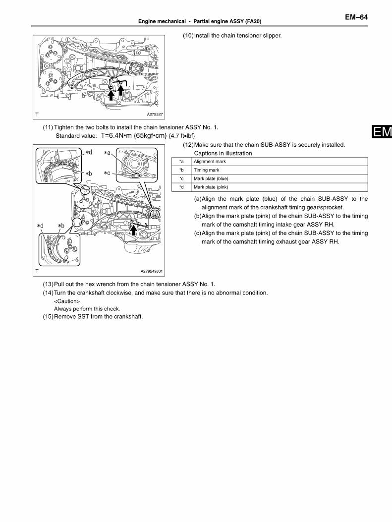
E(10) Install the chain tensioner slipper.
(11) Tighten the two bolts to install the chain tensioner ASSY No. 1. Standard value: T=6.4N•m {65kgf•cm} {4.7 ft•lbf}
(12)Make sure that the chain SUB-ASSY is securely installed.Captions in illustration
(a)Align the mark plate (blue) of the chain SUB-ASSY to thealignment mark of the crankshaft timing gear/sprocket.
(b)Align the mark plate (pink) of the chain SUB-ASSY to the timingmark of the camshaft timing intake gear ASSY RH.
(c)Align the mark plate (pink) of the chain SUB-ASSY to the timing
mark of the camshaft timing exhaust gear ASSY RH.
(13)Pull out the hex wrench from the chain tensioner ASSY No. 1.
(14)Turn the crankshaft clockwise, and make sure that there is no abnormal condition.<Caution>Always perform this check.
(15)Remove SST from the crankshaft.
A279527
A279549J01
*a Alignment mark
*b Timing mark
*c Mark plate (blue)
*d Mark plate (pink)

EM–65Engine mechanical - Partial engine ASSY (FA20)
EM
35. Installation of timing chain/belt cover SUB-ASSY(1) Apply a little coat of engine oil to four new O-rings and install to the engine.(2) Before applying liquid gasket, completely remove the old sealing material attached to the sealing portion.
(3) If there is a gap at the position shown in the figure, fill in the THREE BOND 1217G.
(4) Apply THREE BOND 1217G to the timing chain/belt cover SUB-ASSY at the position shown in the figure.
A281483

Engine mechanical - Partial engine ASSY (FA20)EM–66
M
E<Caution>• Clean and degrease the fitting surface.• Install within 5 min. after applying liquid gasket.
Captions in illustration
(5) Temporarily install the timing chain/belt cover SUB-ASSY using 32 bolts.(6) Tighten the 32 bolts in the order as shown in the figure.
*a Range A *b Boss (five locations)
*c Range B *d Other than ranges A and B
*e 3.5 to 4.5 mm {0.138 to 0.177 in} in diameter *f 2 mm {0.079 in}
*g 12 mm {0.472 in} in diameter *h 2.5 mm {0.098 in}
*i 0.5 mm {0.0197 in} - -
ME-06981

EM–67Engine mechanical - Partial engine ASSY (FA20)
EM
Captions in illustration
Standard value: Bolt A, B
T=10N•m {102kgf•cm} {7.4 ft•lbf}
Bolt C, D
T=25N•m {255kgf•cm} {18.4 ft•lbf}
<Reference>
36. Installation of timing chain/belt cover oil seal
(1) Apply a little coat of engine oil to the inside and outside of the newoil seal.<Caution>• Do not foul the lip.• Do not attach engine oil to the dust seal portion.
(2) Using SST, hammer in the timing chain/belt cover oil seal evenly sothat it is aligned to the end surface of the timing chain/belt coverSUB-ASSY.
SST 398437700<Caution>• Do not hammer in the oil seal obliquely.• Be careful not to deform the oil seal.<Reference>
The depth at which the timing chain/belt cover oil seal ishammered in is allowed within 0 to -1.0 mm {0 to -0.0394 in} fromthe end surface of the timing chain/belt cover SUB-ASSY.
Bolt A Bolt B
Bolt C Bolt D
Bolt type Bolt length (except for head) Bolt type Bolt length (except for head)
Bolt A 20 mm {0.787 in} Bolt B 25 mm {0.984 in}
Bolt C 60 mm {2.362 in} Bolt D 50 mm {1.969 in}
A281484J01
ME-06639

Engine mechanical - Partial engine ASSY (FA20)EM–68
M
E37. Installation of crankshaft pulley(1) Install the crankshaft pulley spacer.(2) Install a new O-ring to the crankshaft pulley spacer.
(3) Install so that the knock hole of the crankshaft pulley and the knockpin of the crankshaft pulley spacer match.Captions in illustration
(4) Apply engine oil to the washer and bolt threads of the crankshaft pulley set bolt.(5) Use the SST to lock the crankshaft pulley, and tighten the crankshaft pulley set bolt.
SST 18355AA000, 18334AA000
Standard value: T=20N•m {204kgf•cm} {14.8 ft•lbf}
(6) As shown in the figure, using a marker, draw a reference line (A)
on the crankshaft pulley set bolt and end line (B) on the crankpulley at the same level of the line marked on the crankshaft pulleyset bolt head portion.
Captions in illustration
<Reference>Lines are marked at an interval of 90° on the crankshaft pulley set
bolt head portion.
(7) Use SST to lock the crankshaft pulley, and further-tighten thecrankshaft pulley set bolt by 90° to the angle where reference line(A) and end line (B) are aligned.
SST 18355AA000, 18334AA000Captions in illustration
38. Installation of thermostat
(1) Install a new gasket to the thermostat.
ME-06538
*1 Knock hole
*2 Knock pin
*a Rotate
*b Hold
A281493J01
*a Reference line (A)
*b End line (B)
ME-06638
*a Reference line (A)
*b End line (B)

EM–69Engine mechanical - Partial engine ASSY (FA20)
EM
39. Installation of water outlet(1) Set the thermostat to the oil pan SUB-ASSY, and install the water
outlet with two bolts.
Standard value: T=6.4N•m {65kgf•cm} {4.7 ft•lbf}
40. Installation of engine water pump ASSY(1) Using a new gasket, install the water pump ASSY with five bolts.
Standard value: T=6.4N•m {65kgf•cm} {4.7 ft•lbf}
41. Installation of water pump pulley(1) Temporarily- tighten the three bolts to the water pump pulley.
(2) Fix the water pump pulley using SST.
SST 18355AA000, 18334AA030
(3) Tighten the three bolts. Standard value: T=14N•m {143kgf•cm} {10.3 ft•lbf}
42. Installation of pump drive case ASSY(1) Apply THREE BOND 1217G to the pump drive case ASSY as
shown in the figure.Captions in illustration
<Caution>• Clean and degrease the fitting surface.• Install within 5 min. after applying liquid gasket.
A281051
A279726
CO-03051
A281430J01
*A Cross section A - A
*1 THREE BOND 1217G
*a Application area of liquid gasket: within 1 mm {0.039 in} from edge
*b Diameter of liquid gasket: 2 to 4 mm {0.079 to 0.158 in}

Engine mechanical - Partial engine ASSY (FA20)EM–70
M
E(2) Tighten the three bolts to install the pump drive case ASSY. Standard value: T=19N•m {194kgf•cm} {14.0 ft•lbf}
43. Installation of ventilation valve SUB-ASSY(1) Apply THREE BOND 1324 to the ventilation valve SUB-ASSY.
(2) Install the ventilation valve SUB-ASSY to the cylinder head block. Standard value: T=23N•m {235kgf•cm} {17.0 ft•lbf}
44. Installation of water inlet pipe(1) Install two new O-rings to the cylinder block.
(2) Install the water inlet pipe with four bolts.
Standard value: T=6.4N•m {65kgf•cm} {4.7 ft•lbf}
A278730
A092670J01
A278795
A280856
A279573

EM–71Engine mechanical - Partial engine ASSY (FA20)
EM
45. Installation of oil level gauge guide(1) Install a new O-ring to the oil level gauge guide.(2) Apply engine oil to the O-ring and install the oil level gauge guide with a bolt.
Standard value: T=6.4N•m {65kgf•cm} {4.7 ft•lbf}(3) Install the oil level gauge SUB-ASSY.
46. Installation of cylinder head plate RR (transmission M/T)(1) Apply THREE BOND 1217G to the camshaft housing SUB-ASSY
RH as shown in the figure.Captions in illustration
<Caution>• Clean and degrease the fitting surface.• Install within 5 min. after applying liquid gasket.
(2) Install the cylinder head plate RR with three bolts. Standard value: T=16N•m {163kgf•cm} {11.8 ft•lbf}
47. Installation of vacuum pump ASSY (transmission A/T).(1) Apply THREE BOND 1217G to the camshaft housing SUB-ASSY
RH as shown in the figure.Captions in illustration
<Caution>• Clean and degrease the fitting surface.• Install within 5 min. after applying liquid gasket.
(2) Install a new O-ring.(3) Tighten the three bolts to install the vacuum pump ASSY.
Standard value: T=16N•m {163kgf•cm} {11.8 ft•lbf}
A279600J01
*a 2.0 to 4.0 mm {0.079 to 0.158 in} in diameter
*b 1.0 mm {0.0394 in} or less
*c Groove
A278731
A279600J01
*a 2.0 to 4.0 mm {0.079 to 0.158 in} in diameter
*b 1.0 mm {0.0394 in} or less
*c Groove
C260987
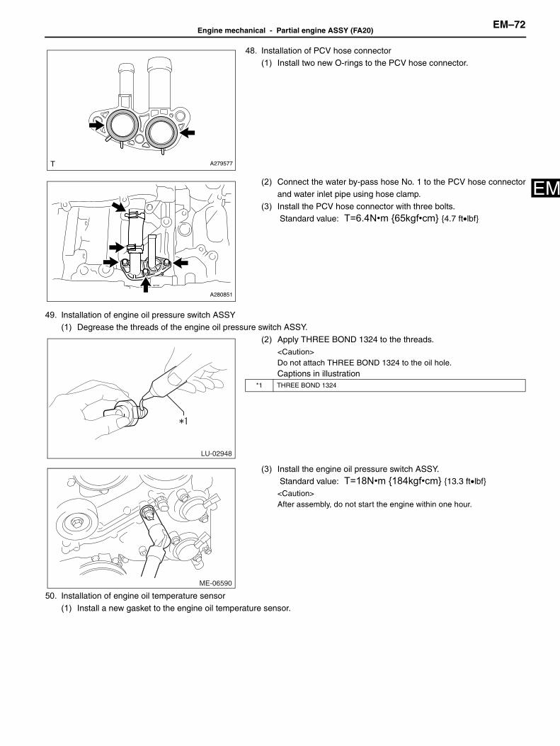
Engine mechanical - Partial engine ASSY (FA20)EM–72
M
E48. Installation of PCV hose connector(1) Install two new O-rings to the PCV hose connector.
(2) Connect the water by-pass hose No. 1 to the PCV hose connectorand water inlet pipe using hose clamp.
(3) Install the PCV hose connector with three bolts. Standard value: T=6.4N•m {65kgf•cm} {4.7 ft•lbf}
49. Installation of engine oil pressure switch ASSY(1) Degrease the threads of the engine oil pressure switch ASSY.
(2) Apply THREE BOND 1324 to the threads.<Caution>Do not attach THREE BOND 1324 to the oil hole.Captions in illustration
(3) Install the engine oil pressure switch ASSY. Standard value: T=18N•m {184kgf•cm} {13.3 ft•lbf}<Caution>After assembly, do not start the engine within one hour.
50. Installation of engine oil temperature sensor
(1) Install a new gasket to the engine oil temperature sensor.
A279577
A280851
LU-02948
*1 THREE BOND 1324
ME-06590

EM–73Engine mechanical - Partial engine ASSY (FA20)
EM
(2) Install the engine oil temperature sensor. Standard value: T=18N•m {184kgf•cm} {13.3 ft•lbf}
51. Installation of camshaft timing oil control valve ASSY(1) Install the back-up ring to the camshaft timing oil control valve
ASSY (bank 2 exhaust side).
Captions in illustration
(2) Install a new O-ring to the camshaft timing oil control valve ASSY(bank 2 exhaust side).
(3) Apply engine oil to O-ring.
(4) Install the camshaft timing oil control valve ASSY (bank 2 exhaustside) using two bolts.
Standard value: T=6.4N•m {65kgf•cm} {4.7 ft•lbf}(5) Install the back-up ring to the camshaft timing oil control valve
ASSY (bank 2 intake side).
(6) Install a new O-ring to the camshaft timing oil control valve ASSY(bank 2 intake side).
(7) Apply engine oil to O-ring.
(8) Install the camshaft timing oil control valve ASSY (bank 2 intake
side) using two bolts. Standard value: T=6.4N•m {65kgf•cm} {4.7 ft•lbf}
(9) Install the back-up ring to the camshaft timing oil control valve
ASSY (bank 1 exhaust side).(10) Install a new O-ring to the camshaft timing oil control valve ASSY
(bank 1 exhaust side).
(11) Apply engine oil to O-ring.
(12) Install the camshaft timing oil control valve ASSY (bank 1 exhaustside) using two bolts. Standard value: T=6.4N•m {65kgf•cm} {4.7 ft•lbf}
(13) Install the back-up ring to the camshaft timing oil control valveASSY (bank 1 intake side).
(14) Install a new O-ring to the camshaft timing oil control valve ASSY
(bank 1 intake side).(15)Apply engine oil to O-ring.
A280848
A276534J01
*1 O-ring
*2 Back-up ring
A280847
A280846
A280845

Engine mechanical - Partial engine ASSY (FA20)EM–74
M
E(16) Install the camshaft timing oil control valve ASSY (bank 1 intakeside) using two bolts. Standard value: T=6.4N•m {65kgf•cm} {4.7 ft•lbf}
52. Installation of camshaft position sensor(1) Install a new O-ring to the camshaft position sensor (bank 2 exhaust side).(2) Apply engine oil to O-ring.
(3) Install the camshaft position sensor (bank 2 exhaust side) using abolt. Standard value: T=6.4N•m {65kgf•cm} {4.7 ft•lbf}
(4) Install a new O-ring to the camshaft position sensor (bank 2 intake side).(5) Apply engine oil to O-ring.
(6) Install the camshaft position sensor (bank 2 intake side) using abolt. Standard value: T=6.4N•m {65kgf•cm} {4.7 ft•lbf}
(7) Install a new O-ring to the camshaft position sensor (bank 1 exhaust side).(8) Apply engine oil to O-ring.
(9) Install the camshaft position sensor (bank 1 exhaust side) using abolt. Standard value: T=6.4N•m {65kgf•cm} {4.7 ft•lbf}
(10) Install a new O-ring to the camshaft position sensor (bank 1 intake side).(11) Apply engine oil to O-ring.
A280844
A280843
A280842
A280841

EM–75Engine mechanical - Partial engine ASSY (FA20)
EM
(12) Install the camshaft position sensor (bank 1 intake side) using abolt. Standard value: T=6.4N•m {65kgf•cm} {4.7 ft•lbf}
53. Installation of crank position sensor(1) Install the crank position sensor using a bolt.
Standard value: T=6.4N•m {65kgf•cm} {4.7 ft•lbf}
54. Installation of knock control sensor(1) Install the two knock control sensors in the direction shown in the
figure using two bolts.
Standard value: T=24N•m {245kgf•cm} {17.7 ft•lbf}Captions in illustration
55. Installation of engine water temperature sensor(1) Install the engine water temperature sensor, using a new gasket.
Standard value: T=18N•m {184kgf•cm} {13.3 ft•lbf}<Caution>When a torque wrench extended with a union nut wrench is used, theactual tightening torque becomes over-torque if the part is tighteneduntil the torque wrench reading reaches the specified tighteningtorque. (For the procedures, refer to IN?5.)
A280840
A280839
A281038J01
Engine front
A280837

Engine mechanical - Partial engine ASSY (FA20)EM–76
M
E56. Installation of oil filter union(1) Install the oil filter union.
Standard value: T=45N•m {459kgf•cm} {33.2 ft•lbf}
57. Installation of oil filter SUB-ASSY(1) Apply a little coat of engine oil to the seal rubber portion of a new oil filter SUB-ASSY.(2) Tighten the oil filter SUB-ASSY by hand.
<Caution>Be careful not to damage the seal rubber of the oil filter SUB-ASSY.
(3) Using SST, tighten the oil filter SUB-ASSY.
SST 18332AA020 Standard value: Specified tightening torque
T=14N•m {143kgf•cm} {10.3 ft•lbf}When using SST, calculate the following formula.
Calculation T2 = L2/(L1 + L2) × T1
<Reference>
• This torque is valid when SST and a torque wrench are aligned.• Install SST and a torque wrench so that they are aligned.
58. Installation of oil filler cap SUB-ASSY(1) Install the oil filler cap SUB-ASSY.
A281050
T1 14 N•m {143 kgf•cm, 10.3 ft•lbf}
T2 Tightening torque
L1 SST length (0.080 m {3.150 in})
L2 Torque wrench length (m)
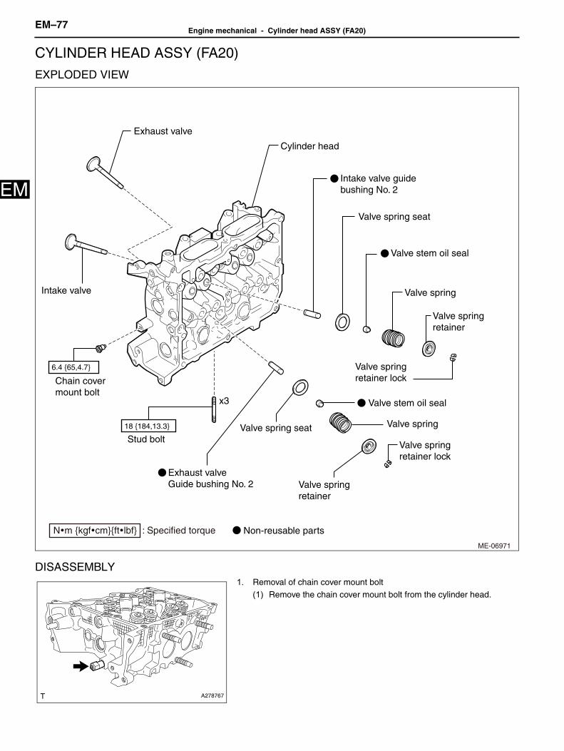
EM–77Engine mechanical - Cylinder head ASSY (FA20)
EM
Engine/hybrid systemEngine mechanicalCYLINDER HEAD ASSY (FA20)
EXPLODED VIEW
DISASSEMBLY1. Removal of chain cover mount bolt
(1) Remove the chain cover mount bolt from the cylinder head.
ME-06971
Cylinder head
Valve spring
x3
Valve spring retainer
Valve spring seat
Valve spring retainer lock
Valve spring seat
Valve spring
Valve spring retainer
Valve spring retainer lock
Non-reusable parts
Intake valve
Intake valve guide bushing No. 2
Exhaust valve
Exhaust valveGuide bushing No. 2
Stud bolt
Chain cover mount bolt
Valve stem oil seal
Valve stem oil seal
6.4 {65,4.7}
18 {184,13.3}
N�m {kgf�cm}{ft�lbf} : Specified torque
A278767

Engine mechanical - Cylinder head ASSY (FA20)EM–78
M
E2. Removal of stud bolt<Reference>Replace the stud bolt if deformed or damaged in the threaded portion.
(1) Remove the six stud bolts from the cylinder head.Captions in illustration
3. Removal of intake valve<Caution>During work, place a cloth, etc. to avoid scratching the mating surface of the cylinder head.<Reference>• Mark each part to prevent confusion.
• Organize disassembled parts by their installation positions.(1) Compress the valve spring and remove the valve spring retainer
lock using SST.
SST 0920287002000
(2) Remove the valve, valve spring retainer, valve spring and valve spring seat.
4. Removal of exhaust valve<WARNING>• Metal sodium is included in the exhaust valve.Pay special attention to dealing and disposal of metal sodium because it is strong
alkaline enough to cause a high chemical reaction. • Do not disassemble because metal sodium may cause vision loss, burn and fire due to chemical reaction.• It is safe as long as metal sodium is sealed in exhaust valve and not exposed to the air.• If exhaust valve is broken, remove the exhaust valve and dispose of the metal sodium.(Perform the pre-disposal process and
disposal process.)• Do not break the exhaust valve intentionally to retrieve the metal sodium.
A278768J01
*a Bank 1
*b Bank 2
ME-06552

EM–79Engine mechanical - Cylinder head ASSY (FA20)
EM
• To identify the exhaust valve including metal sodium, refer to itsengraved mark.Captions in illustration
<Caution>During work, place a cloth, etc. to avoid scratching the mating surface of the cylinder head.<Reference>• Mark each part to prevent confusion.• Organize disassembled parts by their installation positions.
(1) Compress the valve spring and remove the valve spring retainerlock using SST.SST 0920287002000
(2) Remove the valve, valve spring retainer, valve spring and valve spring seat.
5. Removal of valve stem oil seal(1) Remove the eight valve stem oil seals.
<Caution>• During work, place a cloth, etc. to avoid scratching the mating
surface of the cylinder head.• Use special care not to damage the cylinder head and guide
during work.
6. Removal of intake valve guide bushing No. 2
(1) Place the cylinder head on a wooden piece etc facing the combustion chamber upward.
ME-06632
*a Engraved mark (identification: E2H•FA20 engine)
ME-06553
A278770

Engine mechanical - Cylinder head ASSY (FA20)EM–80
M
E(2) Using SST and a hammer, punch out intake valve guide bushingNo. 2.SST 499765700<Caution>• Place a wooden piece wrapped with a cloth to stabilize the cylinder
head before work.• Use special care not to damage the cylinder head during work.
7. Removal of exhaust valve guide bushing No. 2(1) Place the cylinder head on a wooden piece etc facing the combustion chamber upward.
(2) Using SST and a hammer, punch out exhaust valve guide bushing
No. 2.SST 499765700<Caution>• Place a wooden piece wrapped with a cloth to stabilize the cylinder
head before work.• Use special care not to damage the cylinder head during work.
8. Disposal of exhaust valve<WARNING>• Metal sodium is included in the exhaust valve.Pay special attention to dealing and disposal of metal sodium because it is strong
alkaline enough to cause a high chemical reaction. • Do not disassemble because metal sodium may cause vision loss, burn and fire due to chemical reaction.• It is safe as long as metal sodium is sealed in exhaust valve and not exposed to the air.• If exhaust valve is broken, remove the exhaust valve and dispose of the metal sodium.(Perform the pre-disposal process and
disposal process.)• Do not break the exhaust valve intentionally to retrieve the metal sodium.
ME-06554
ME-06555

EM–81Engine mechanical - Cylinder head ASSY (FA20)
EM
• To identify the exhaust valve including metal sodium, refer to itsengraved mark.Captions in illustration
<Caution><Pre-disposal process>• When industrial waste disposal process turns out to be dissolution, the process can be performed.• If exhaust valve is broken, remove from the cylinder head and dispose in the same method of general steel after performing the
process.• When performing the process, observe the followings.
(a) Prepare an extinguisher at hand.(b) Wear protective goggles.(c) Wear rubber gloves.
<Disposal process>1. Wearing rubber gloves, remove the broken exhaust valve from the cylinder head.2. Prepare a large container (bucket or oil tin etc.) in a well ventilated place, and fill the container with over 10 liter of water.
3. Put in the broken exhaust valve longitudinally using a large tweezers orpliers.<Caution>• Let the broken exhaust valve completely sunken.• Keep fire away from the container because hydrogen gas generates
due to chemical reaction.• Stay away at least 2 to 3 m {6.6 to 9.8 ft} from the container
because of an intense chemical reaction.
4. After chemical reaction finishes (after the elapse of four to five hours), take out the exhaust valve using a large tweezers or plierscarefully, and dispose in the same disposal method as other parts.<Caution>• For disposal of chemically-reacted liquid waste (sodium hydroxide), follow all government and local regulations concerning
disposal of liquid waste.• If chemically-reacted liquid waste (sodium hydroxide) touches skin, wash it off immediately with a sufficient amount of water.
INSPECTION1. Inspection of cylinder head
(1) Visually check that there are no cracks, scratches or other damage.(2) Use liquid penetrant testing (red check) on the important sections to check for fissures.(3) Check that there are no marks of gas leaking or water leaking on gasket attachment surface.
(4) Check the warping of the cylinder head mating surface that mates with cylinder block at the locations shown in the figureusing a straight edge and thickness gauge.
ME-06632
*a Engraved mark (identification: E2H•FA20 engine)
ME-06635

Engine mechanical - Cylinder head ASSY (FA20)EM–82
M
ECaptions in illustration
Limit: 0.035 mm {0.00138 in}Grinding limit of cylinder head: 98.4 mm {3.874 in} or lessStandard value for cylinder head height: 98.5 mm {3.878 in}
<Reference>• Measurement should be performed at a temperature of 20°C {68°F}.• If there is warpage on the cylinder head mating surface, the cylinder head bolt tightening torque and angle tightening
may be improper.When installing the cylinder head, make sure that tightening to specified torque and angletightening are performed precisely according to the operation procedures.
• If it exceeds the limit, correct the surface by grinding it with a surface grinder or replace the cylinder head.
• When the cylinder head is replaced, lap each valve.
2. Inspection of intake valve(1) Check the valve flange and stem for damage, wear or deformation.
*a Bank 1 *b Bank 2
A278772J01

EM–83Engine mechanical - Cylinder head ASSY (FA20)
EM
(2) Using a caliper, measure the whole length of the valve.Captions in illustration
Standard value: 103.3 mm {4.067 in}
(3) Using a caliper, measure the thickness of the valve head.Captions in illustration
Standard value: 0.8 to 1.2 mm {0.0315 to 0.0472 in}
<Reference>• It is possible to differentiate between the intake valve and the
exhaust valve by their overall length.
• If it is not within the specified value, replace the valve with anew part.
• When the valve is replaced, lap the valve.
(4) Check the valve stem outer diameter using micrometer.
Standard value: 5.455 to 5.470 mm {0.2148 to 0.2154 in}<Reference>• Measurement should be performed at a temperature of 20°C
{68°F}.
• Measure the outer diameter of the valve stem at the six
locations as shown in the figure, and read the value of mostworn location.
• If it is not within the specified value, replace the valve with a
new part.• When the valve is replaced, lap the valve.
3. Inspection of exhaust valve(1) Check the valve flange and stem for damage, wear or deformation.
(2) Using a caliper, measure the whole length of the valve.Captions in illustration
Standard value: 95.1 mm {3.744 in}
A121380J12
*a Overall length
A121379J06
*a Thickness
A121381
A121380J12
*a Overall length

Engine mechanical - Cylinder head ASSY (FA20)EM–84
M
E(3) Using a caliper, measure the thickness of the valve head.Captions in illustration
Standard value: 1.0 to 1.4 mm {0.039 to 0.055 in}<Reference>
• It is possible to differentiate between the intake valve and theexhaust valve by their overall length.
• If it is not within the specified value, replace the valve with a
new part.• When the valve is replaced, lap the valve.
(4) Check the valve stem outer diameter using micrometer.Standard value: 5.445 to 5.460 mm {0.21437 to 0.21496 in}
<Reference>• Measurement should be performed at a temperature of 20°C
{68°F}.
• Measure the outer diameter of the valve stem at the sixlocations as shown in the figure, and read the value of mostworn location.
• If it is not within the specified value, replace the valve with anew part.
• When the valve is replaced, lap the valve.
4. Inspection of valve guide bushing oil clearance
(1) Using a caliper gauge, measure the inner diameter of valve guidebushing.Standard value: 5.500 to 5.512 mm {0.21654 to 0.21701 in}
<Reference>• Measurement should be performed at a temperature of 20°C
{68°F}.
• Measure the inner diameter of the valve guide bushing at thesix locations as shown in the figure, and read the value of mostworn location.
• If it is not within the standard value, replace the valve guidebushing.
(2) Calculate the oil clearance between valve and valve guide
bushing.Standard value (intake): 0.030 to 0.057 mm
{0.00118 to 0.00224 in}
Standard value (exhaust): 0.040 to 0.067 mm{0.00157 to 0.00264 in}
<Reference>
• Oil clearance = valve guide bushing inner dia. - Valve stemouter dia.
• If the clearance between valve and valve guide bushing
exceeds the standard, replace the valve or valve guide,whichever shows the greater amount of wear or damage.
• When the valve is replaced, lap the valve.
5. Inspection of valve adjusting shim clearance
(1) Visually check the valve adjusting shim for any damage.
A121379J06
*a Thickness
A121381
A278774

EM–85Engine mechanical - Cylinder head ASSY (FA20)
EM
(2) Measure the valve stem end outer diameter using micrometer.Standard value (intake): 5.455 to 5.470 mm
{0.21476 to 0.21535 in}
Standard value (exhaust): 5.445 to 5.460 mm{0.21437 to 0.21496 in}
<Reference>
• Measurement should be performed at a temperature of20°C{68°F}.
• Measure the outer diameter of the valve stem end at the two
locations as shown in the figure, and read the value of mostworn location.
• If it is not within the specified value, replace the valve with a
new part.• When the valve is replaced, lap the valve.
(3) Using a caliper gauge, measure the inner diameter of valve
adjusting shim.Standard value: 5.500 to 5.560 mm {0.21654 to 0.21890 in}<Reference>
• Measurement should be performed at a temperature of 20°C{68°F}.
• Measure the inner diameter of the valve adjusting shim at the
two locations as shown in the figure, and read the value ofmost worn location.
• If it is not within the standard value, replace the valve adjusting
shim.• If the valve adjusting shim has to be replaced, check the valve
clearance and replace with the suitable valve adjusting shim.
(4) Calculate the clearance between valve and valve adjusting shim.Standard value: 0.030 to 0.115 mm {0.00118 to 0.00453 in}<Reference>
• Valve adjusting shim clearance = Valve adjusting shim inner dia. - Valve stem end outer dia.• If it exceeds the standard, replace the valve or valve adjusting shim, whichever shows the greater amount of wear or
damage.
• When the valve is replaced, lap the valve.• If the valve adjusting shim has to be replaced, check the valve clearance and replace with the suitable valve adjusting
shim.
6. Inspection of intake valve seat
(1) Check the valve seat for damage and deformation.(2) Clean the valve and valve seat.
(3) Apply a thin coat of engine oil to the valve stem, and apply red dye
evenly on the valve face.Captions in illustration
(4) Slowly insert the valve applied with red dye into the valve guide bushing, lightly press the valve against the valve seatwithout turning the valve, and then slowly pull out the valve.
(5) Check the seating width of valve seat as shown in the figure, using a caliper gauge.
A278794
A278780
A278781J01
*a Valve stem
*b Valve face

Engine mechanical - Cylinder head ASSY (FA20)EM–86
M
ECaptions in illustration
Standard (A): 0.8 to 1.6 mm {0.032 to 0.063 in} (face at 90° in the figure)<Reference>
• Check the seating width between valve and valve seat by measuring the width of red dye on the seating surface ofvalve seat.
• If the seating width between valve and valve seat is not within standard, correct the seating surface of valve seat
using the valve seat cutter.• When the red dye does not appear seamlessly on the valve seat seating surface, lap the valve.• When the red dye does not appear seamlessly on the valve seat seating surface even after lapping the valve, correct
the valve seat seating surface using the valve seat cutter.(6) Wipe off the red dye on the valve and valve seat completely.
*a Bank 1 *b Bank 2
A279579J01

EM–87Engine mechanical - Cylinder head ASSY (FA20)
EM
(7) Apply a thin coat of engine oil to the valve stem, and apply red dyeevenly on the valve and valve seat seating surface.Captions in illustration
(8) Slowly insert the valve into the valve guide bushing, lightly press the valve against the valve seat without turning thevalve, and then slowly pull out the valve.
(9) Check the seating position between valve and valve seat.
Captions in illustration
Standard (Seating position between valve and valve seat): Center all around the valve
<Reference>
• Check the seating position between valve and valve seat bychecking the position of red dye on the valve face.
• If the seating position between valve and valve seat is not at
the center of valve face, correct the seating surface of valveseat using the valve seat cutter.
(10)After inspection, wipe off the red dye completely.
7. Inspection of exhaust valve seat
(1) Check the valve seat for damage and deformation.(2) Clean the valve and valve seat.
(3) Apply a thin coat of engine oil to the valve stem, and apply red dye
evenly on the valve face.Captions in illustration
(4) Slowly insert the valve applied with red dye into the valve guide bushing, lightly press the valve against the valve seatwithout turning the valve, and then slowly pull out the valve.
(5) Check the seating width of valve seat as shown in the figure, using a caliper gauge.
A279580J01
*a Valve stem
*b Seating surface
A281044J01
*a Seating position
A278781J01
*a Valve stem
*b Valve face

Engine mechanical - Cylinder head ASSY (FA20)EM–88
M
ECaptions in illustration
Standard (A): 1.1 to 1.7 mm {0.043 to 0.067 in} (face at 90° in the figure)<Reference>
• Check the seating width between valve and valve seat by measuring the width of red dye on the seating surface ofvalve seat.
• If the seating width between valve and valve seat is not within standard, correct the seating surface of valve seat
using the valve seat cutter.• When the red dye does not appear seamlessly on the valve seat seating surface, lap the valve.• When the red dye does not appear seamlessly on the valve seat seating surface even after lapping the valve, correct
the valve seat seating surface using the valve seat cutter.(6) Wipe off the red dye on the valve and valve seat completely.
*a Bank 1 *b Bank 2
A279603J01

EM–89Engine mechanical - Cylinder head ASSY (FA20)
EM
(7) Apply a thin coat of engine oil to the valve stem, and apply red dyeevenly on the valve and valve seat seating surface.Captions in illustration
(8) Slowly insert the valve into the valve guide bushing, lightly press the valve against the valve seat without turning thevalve, and then slowly pull out the valve.
(9) Check the seating position between valve and valve seat.
Captions in illustration
Standard (Seating position between valve and valve seat): Center all around the valve
<Reference>
• Check the seating position between valve and valve seat bychecking the position of red dye on the valve face.
• If the seating position between valve and valve seat is not at
the center of valve face, correct the seating surface of valveseat using the valve seat cutter.
(10)After inspection, wipe off the red dye completely.
8. Inspection of valve spring
(1) Check the valve spring for damage and deformation.(2) Using a caliper, measure the free length of the valve spring.
Standard value: 41.06 mm {1.617 in}
<Reference>• Measurement should be performed at a temperature of 20°C
{68°F}.
• If it is not within the specified value, replace the valve spring.
(3) Using a valve spring tester, measure the load/length of the valve spring.
Standard value: 182 to 210N/33.0mm {1.299in}552 to 610N/22.0mm {0.866in}
<Reference>
• Measurement should be performed at a temperature of 20°C {68°F}.• If it is not within the specified value, replace the valve spring.
A279604J01
*a Valve stem
*b Seating surface
A281045J01
*a Seating position
A051437

Engine mechanical - Cylinder head ASSY (FA20)EM–90
M
E(4) Using a right angle gauge and caliper, measure the squareness ofthe spring.Limit (a): 2.5° (1.8 mm) {0.0710 in} or less
<Reference>• Measurement should be performed at a temperature of 20°C
{68°F}.
• To check the squareness of the valve spring, stand the valvespring on a flat table and check its deflection at the top of thevalve spring using a right angle gauge.
• If it is not within the specified value, replace the valve spring.
ASSEMBLY1. Installation of intake valve guide bushing No. 2
(1) Before installing the valve guide bushing, make sure that neither scratches nor damages exist on the inner surface of
valve guide bushing installation holes of cylinder head.(2) Draw a reference line for insert on the new valve guide bushing at
the position shown in the figure using a marker.
Captions in illustration
<Reference>A reference line for insert is used as a guide when tapping-in thevalve guide bushing.
(3) Place the cylinder head on a wooden piece etc facing the combustion chamber downward.(4) Apply an enough coat of engine oil to the valve guide bushing, and set the valve guide bushing on the cylinder head.
(5) Using SST and a hammer, tap in the valve guide bushing down tothe reference line for insert.SST 499765700<Caution>• During work, place a cloth, etc. to avoid scratching the mating
surface of the cylinder head.• Use special care not to damage the cylinder head during work.
A146307J05
ME-06982
*a Reference line for insert
ME-06556

EM–91Engine mechanical - Cylinder head ASSY (FA20)
EM
(6) While measuring the protrusion amount shown in the figure usinga caliper gauge, tap in the valve guide bushing within the range ofthe standard.
Captions in illustration
Specified protrusion amount: 11.4 to 11.8 mm {0.449 to 0.466 in}<Caution>• During work, place a cloth, etc. to avoid scratching the mating
surface of the cylinder head.• Use special care not to damage the cylinder head during work.<Reference>
Be careful not to tap-in excessively by repeating the steps ofTapping-in several times → Measurement → Tapping-in severaltimes → Measurement when installing the valve guide bushing.
(7) Place the cylinder head on a wooden piece etc facing the combustion chamber upward.<Caution>• Place a wooden piece wrapped with a cloth to stabilize the cylinder head before work.• Use special care not to damage the cylinder head during work.
(8) Using a hand reamer and pin vise, grind the inner surface of thevalve guide bushing so that the oil clearance is within the specified
value.Standard value: 5.500 to 5.512 mm {0.21654 to 0.21701 in}
(20°C {68°F})<Caution>By widening the hole slowly and evenly using a hand reamer, grind sothat it is within the specified value.<Reference>
• Apply engine oil to a hand reamer.• If the inner surface of valve guide bushing is damaged, the
edge of the hand reamer should be slightly ground with an
abrasive sheet (No. 400).• If the inner surface of valve guide bushing becomes lustrous
and the hand reamer does not chip, use a new hand reamer or
remedy the hand reamer.
(9) After reaming, clean the valve guide bushing to remove chips.(10)Using a caliper gauge, measure the inner diameter of valve guide bushing to calculate the oil clearance between the
valve and valve guide bushing.(11) Check the seating width between valve and valve seat.
2. Installation of exhaust valve guide bushing No. 2(1) Before installing the valve guide bushing, make sure that neither scratches nor damages exist on the inner surface of
valve guide bushing installation holes of cylinder head.(2) Draw a reference line for insert on the new valve guide bushing at
the position shown in the figure using a marker.
Captions in illustration
<Reference>A reference line for insert is used as a guide when tapping-in thevalve guide bushing.
(3) Place the cylinder head on a wooden piece etc facing the combustion chamber downward.
A278778J01
*a Protrusion amount
A281465
ME-06983
*a Reference line for insert

Engine mechanical - Cylinder head ASSY (FA20)EM–92
M
E(4) Apply an enough coat of engine oil to the valve guide bushing, and set the valve guide bushing on the cylinder head.(5) Using SST and a hammer, tap in the valve guide bushing down to
the reference line for insert.
SST 499765700<Caution>• During work, place a cloth, etc. to avoid scratching the mating
surface of the cylinder head.• Use special care not to damage the cylinder head during work.
(6) While measuring the protrusion amount shown in the figure using
a caliper gauge, tap in the valve guide bushing within the range ofthe standard.Captions in illustration
Specified protrusion amount: 11.4 to 11.8 mm {0.449 to 0.466 in}<Caution>• During work, place a cloth, etc. to avoid scratching the mating
surface of the cylinder head.• Use special care not to damage the cylinder head during work.<Reference>Be careful not to tap-in excessively by repeating the steps of
Tapping-in several times → Measurement → Tapping-in severaltimes → Measurement when installing the valve guide bushing.
(7) Place the cylinder head on a wooden piece etc facing the combustion chamber upward.<Caution>• Place a wooden piece wrapped with a cloth to stabilize the cylinder head before work.• Use special care not to damage the cylinder head during work.
(8) Using a hand reamer and pin vise, grind the inner surface of thevalve guide bushing so that the oil clearance is within the specified
value.Standard value: 5.500 to 5.512 mm {0.21654 to 0.21701 in}
(20°C {68°F})<Caution>By widening the hole slowly and evenly using a hand reamer, grind sothat it is within the specified value.<Reference>• Apply engine oil to a hand reamer.
• If the inner surface of valve guide bushing is damaged, theedge of the hand reamer should be slightly ground with anabrasive sheet (No. 400).
• If the inner surface of valve guide bushing becomes lustrousand the hand reamer does not chip, use a new hand reamer orremedy the hand reamer.
(9) After reaming, clean the valve guide bushing to remove chips.
ME-06557
A279607J01
*a Protrusion amount
A278779

EM–93Engine mechanical - Cylinder head ASSY (FA20)
EM
(10)Using a caliper gauge, measure the inner diameter of valve guide bushing to calculate the oil clearance between thevalve and valve guide bushing.
(11) Check the seating width between valve and valve seat.
3. Correction of intake valve seat<Caution>• Always perform cutting while checking the valve seating position and width.• Cut with a care to avoid any steps, and release force gradually towards end.
(1) Using a cutter head with 45°, cut so that the seating width is widerthan the specified value.
(2) Lap the valve.(3) Check the seating position between valve and valve seat.
<Reference>This procedure is necessary to select a seat cutter to be used in the following step.
(4) Using the 30° or 75° seat cutter, correct the valve seat so that the seating width between valve and valve seat becomes
the standard value.
A278782J01

Engine mechanical - Cylinder head ASSY (FA20)EM–94
M
E<Caution>• Always perform cutting while checking the valve seating position and width.• Cut with a care to avoid any steps, and release force gradually towards end.<Reference>Select a proper valve seat cutter according to the following table.
(5) Lap the valve.
4. Correction of exhaust valve seat<Caution>• Always perform cutting while checking the valve seating position and width.• Cut with a care to avoid any steps, and release force gradually towards end.
Seating position between valve and valve seat Seat cutter selection
A in the figureWhen the seating position of valve face is high, grind the surface using the 30° seat cutter until seating width between valve and valve seat becomes the standard value.
B in the figureWhen the seating position of valve face is low, grind the surface using the 75° seat cutter until
seating width between valve and valve seat becomes the standard value.
C in the figureWhen the seating position of valve face is at center, grind the surface evenly using the 30° and 75° seat cutters until seating width between valve and valve seat becomes the standard value.
A279608J01
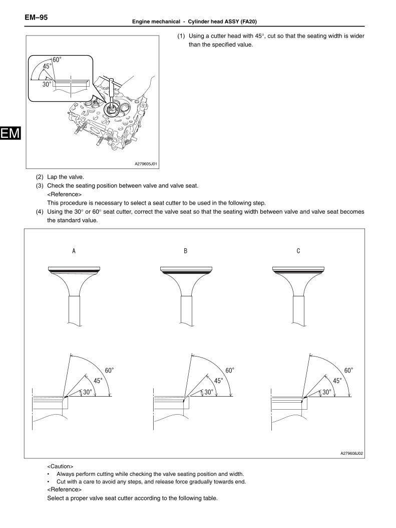
EM–95Engine mechanical - Cylinder head ASSY (FA20)
EM
(1) Using a cutter head with 45°, cut so that the seating width is widerthan the specified value.
(2) Lap the valve.
(3) Check the seating position between valve and valve seat.<Reference>This procedure is necessary to select a seat cutter to be used in the following step.
(4) Using the 30° or 60° seat cutter, correct the valve seat so that the seating width between valve and valve seat becomesthe standard value.
<Caution>• Always perform cutting while checking the valve seating position and width.• Cut with a care to avoid any steps, and release force gradually towards end.<Reference>
Select a proper valve seat cutter according to the following table.
A279605J01
A279608J02

Engine mechanical - Cylinder head ASSY (FA20)EM–96
M
E(5) Lap the valve.
5. Lapping of valve
(1) Apply a thin coat of engine oil to the valve stem, and apply a smallamount of valve compound evenly on the valve face.Captions in illustration
<Reference>• Be careful not to put the valve compound more than necessary.• To avoid damaging the valve guide bushing and valve stem, be
careful not to let the valve compound contact the valve stem.
Seating position between valve and valve seat Seat cutter selection
A in the figureWhen the seating position of valve face is high, grind the surface using the 30° seat cutter until seating width between valve and valve seat becomes the standard value.
B in the figureWhen the seating position of valve face is low, grind the surface using the 60° seat cutter until
seating width between valve and valve seat becomes the standard value.
C in the figureWhen the seating position of valve face is at center, grind the surface evenly using the 30° and 60° seat cutters until seating width between valve and valve seat becomes the standard value.
A278781J01
*a Valve stem
*b Valve face

EM–97Engine mechanical - Cylinder head ASSY (FA20)
EM
(2) Slowly insert the valve applied with the valve compound into thevalve guide bushing, and lap the seating surface between valveand valve seat.
<Reference>• First, lift the valve and strike it against the valve seat twice, and
then slightly turn the valve once. Repeat these steps as one
set.• To prevent the seating width between valve and valve seat from
exceeding the standard value, be careful not to keep turning
the valve while pressing it against the valve seat duringlapping.
• Be careful not to lift the valve too far during lapping in order to
prevent the valve from coming off the valve guide bushing.(3) Wipe off the valve compound on the valve and valve seat
completely after lapping.<Caution>Be careful not to leave any valve compound in order to avoidmalfunction.
(4) Check the seating width and seating position between valve andvalve seat.
6. Installation of intake valve stem oil seal
(1) Apply engine oil to the tip of the new intake valve stem oil seal.Captions in illustration
<Caution>• Be careful with the identification colors of valve stem oil seal.• Wrong assembly between intake side and exhaust side will cause
trouble.(2) Using SST, press in the intake valve stem oil seal fully into the
valve guide bushing by hand.SST 18261AA010<Caution>• During work, place a cloth, etc. to avoid scratching the mating
surface of the cylinder head.• When installing the valve oil seal, press the SST with hands to
install it and never drive the SST with a plastic hammer, otherwisethe valve oil seal can be damaged.
• Do not install the oil seal obliquely.
7. Installation of exhaust valve stem oil seal(1) Using SST, press in the exhaust valve stem oil seal fully into the valve guide bushing by hand.
SST 18261AA010<Caution>• During work, place a cloth, etc. to avoid scratching the mating surface of the cylinder head.• When installing the valve oil seal, press the SST with hands to install it and never drive the SST with a plastic hammer,
otherwise the valve oil seal can be damaged.• Do not install the oil seal obliquely.
A146313J06
*a Intake side
*b Exhaust side
*c Grey
*d Light green
A281043J01

Engine mechanical - Cylinder head ASSY (FA20)EM–98
M
E8. Installation of intake valve<Caution>During work, place a cloth, etc. to avoid scratching the mating surface of the cylinder head.(1) Set the valve spring seat, valve spring and valve spring retainer onto the cylinder head.(2) Apply engine oil to the valve stem of each valve and insert the valve into valve guide bushing.
<Caution>When inserting the valve into valve guide bushing, use special care not to damage the oil seal lip.
(3) Using SST, compress the valve spring and install the valve springretainer lock applied with engine oil.
SST 0920287002000
(4) Using a plastic hammer, tap the tip of the valve stem slightly tosettle the valve spring.
<Caution>Do not strike the valve spring retainer.
9. Installation of exhaust valve<Caution>During work, place a cloth, etc. to avoid scratching the mating surface of the cylinder head.(1) Set the valve spring seat, valve spring and valve spring retainer onto the cylinder head.(2) Apply engine oil to the valve stem of each valve and insert the valve into valve guide bushing.
<Caution>When inserting the valve into valve guide bushing, use special care not to damage the oil seal lip.
(3) Using SST, compress the valve spring and install the valve springretainer lock applied with engine oil.
SST 0920287002000
(4) Using a plastic hammer, tap the tip of the valve stem slightly tosettle the valve spring.
<Caution>Do not strike the valve spring retainer.
ME-06552
A279609
ME-06553
A279610

EM–99Engine mechanical - Cylinder head ASSY (FA20)
EM
10. Installation of stud bolt(1) Install the six stud bolts onto the cylinder head.
Standard value: T=18N•m {184kgf•cm} {13.3 ft•lbf}
Captions in illustration
11. Installation of chain cover mount bolt(1) Install the chain cover mount bolt to the cylinder head LH.
Standard value: T=6.4N•m {65kgf•cm} {4.7 ft•lbf}
A278768J02
*a Bank 1
*b Bank 2
A278767

Engine mechanical - Cylinder block ASSY (FA20)EM–100
M
EEngine/hybrid systemEngine mechanicalCYLINDER BLOCK ASSY (FA20)
EXPLODED VIEW
ME-06972
Crankshaft bearing No. 5
Connecting rod ASSY
Connecting rod bearing
Cylinder block (bank 2 side)
Cylinder block (bank 1 side)
Compression ring No. 1
First time: 10 {102,7.4}
Second time: 25 {255,18.4}
Third time: Further-tighten 92.5°
x2
Non-reusable parts
Piston
Piston pin hole snap ring
Piston pin
Piston pin hole snap ring
Compression ring No. 2
Connecting rod cap
CrankshaftTiming gear key
Connecting rod bearing
Connecting rod cap bolt
Oil ring expander
Oil ring side rail
Oil ring side rail
No. 2, No. 4 crankshaft bearing
No. 1, No. 3 crankshaft bearing
Crankshaft
Piston ring set
N�m {kgf�cm}{ft�lbf} : Specified torque

EM–101Engine mechanical - Cylinder block ASSY (FA20)
EM
DISASSEMBLY1. Removal of piston with connecting rod
(1) Mark each connecting rod cap and piston with a cylinder number.
(2) Turn the crankshaft to the position where the connecting rod cap bolt can be removed.
ME-06973
x7
x5
Sixth time: Further-tighten 60°
Fifth time: 17 {173,12.5}
Fourth time: Loosen 180°
Third time: 35 {357,25.8}
First time: 35 {357,25.8}
Second time: Loosen 180°
x5
x10x10
Washer
x2
O-ring
Engine rear oil seal
Oil separator cover
Crankshaft sensor holder ASSY
Cylinder block tight plug No. 1
Cylinder block plate
Cylinder block tight plug No. 1
Cylinder block tight plug No. 1
6.4 {65,4.7}
37 {377,27.3}
6.4 {65,4.7}6.4 {65,4.7}
37 {377,27.3}
37 {377,27.3}
25 {255,18.4}
Non-reusable parts
N�m {kgf�cm}{ft�lbf} : Specified torque

Engine mechanical - Cylinder block ASSY (FA20)EM–102
M
E(3) Using SST, remove the connecting rod cap bolt to remove theconnecting rod cap.SST 18270AA020
(4) Turn the crankshaft to separate the crankshaft pin and connecting
rod large end.Captions in illustration
<Reference>
When removing the piston with connecting rod No. 1 and No. 3,turn the crankshaft clockwise, on the other hand, when removingthe piston with connecting rod No. 2 and No. 4, turn the crankshaft
counter clockwise.
(5) Push the connecting rod in the direction of the arrow, and removethe piston along with the connecting rod from the cylinder block.
2. Removal of cylinder block SUB-ASSY (bank 1 side)<Caution>Be careful not to scratch the mating surface of cylinder block during work.(1) Move the engine stand so that bank 1 side faces upward.
(2) Remove the five bolts shown in the figure.
A279369
A279370J01
*1 Connecting rod
*2 Crankshaft pin
A279371
A279375

EM–103Engine mechanical - Cylinder block ASSY (FA20)
EM
(3) Loosen the ten cylinder block mounting bolts in the order as shownin the figure.
(4) Remove the 10 bolts to remove the cylinder block (bank 1 side).<Caution>Lift the cylinder block (bank 1 side) slightly, and make sure that the crankshaft is remaining in the cylinder block (bank 2 side).Ifthe cylinder block (bank 1 side) is lifted without care, the crankshaft may be lifted along and fall off from the cylinder block (bank1 side).
3. Removal of crankshaft
(1) Remove the crankshaft from the cylinder block (bank 2 side).
4. Removal of engine rear oil seal
(1) Remove the engine rear oil seal.
5. Removal of O-ring.(1) Remove the O-ring from the cylinder block (bank 2 side).
A279376J01
A279379
A279377

Engine mechanical - Cylinder block ASSY (FA20)EM–104
M
E6. Removal of crankshaft bearing(1) Remove the 10 crankshaft bearings from the cylinder block (bank 1
side and bank 2 side).
Captions in illustration
<Reference>• Organize disassembled parts by their installation positions.
• Remove the bearing by pressing at the opposite side of thelocking lip.
7. Removal of oil separator cover
(1) Remove the 7 bolts to remove the oil separator cover from thecylinder block (bank 1 side).
8. Removal of cylinder block SUB-ASSY (bank 2 side)
(1) Remover the bolt to remove the engine stand from the cylinder block (bank 2 side).
9. Removal of cylinder block plate(1) Remove the 5 bolts to remove the cylinder bock plate from the
cylinder block (bank 2 side).
A279378J01
*1 No. 1, No. 3 crankshaft bearing
*2 No. 2, No. 4 crankshaft bearing
*3 Crankshaft bearing No. 5
*a Bank 1
*b Bank 2
A279366
A279368

EM–105Engine mechanical - Cylinder block ASSY (FA20)
EM
10. Removal of crankshaft sensor holder ASSY(1) Remove the two bolts to remove the crankshaft sensor holder
ASSY from the cylinder block (bank 2 side).
11. Removal of cylinder block tight plug No. 1(1) Remove the three cylinder tight plugs No. 1 from the cylinder block
(bank 1 side and bank 2 side).
Captions in illustration
12. Removal of connecting rod bearing(1) Remove the connecting rod bearing from connecting rod and connecting rod cap.
<Reference>
Organize disassembled parts by their installation positions.
13. Removal of piston ring set<Reference>Organize disassembled parts by their installation positions.
(1) Remove compression ring No. 1 and then, compression ring No. 2in numerical order, using piston ring tool.
(2) Remove the oil rings in the order of oil ring side rail (upper),oil ring side rail (lower), oil ring expander by hand.
A278796
A278799J01
*a Bank 1
*b Bank 2
A094743
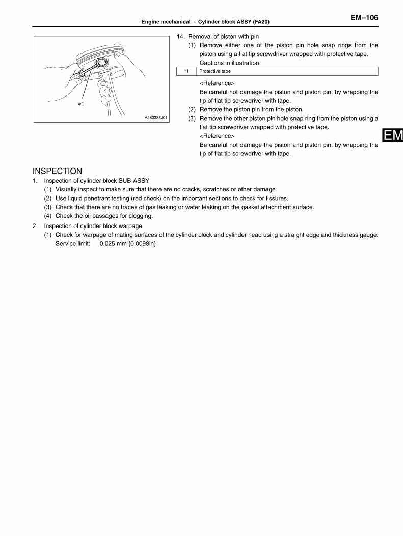
Engine mechanical - Cylinder block ASSY (FA20)EM–106
M
E14. Removal of piston with pin(1) Remove either one of the piston pin hole snap rings from the
piston using a flat tip screwdriver wrapped with protective tape.
Captions in illustration
<Reference>Be careful not damage the piston and piston pin, by wrapping thetip of flat tip screwdriver with tape.
(2) Remove the piston pin from the piston.(3) Remove the other piston pin hole snap ring from the piston using a
flat tip screwdriver wrapped with protective tape.
<Reference>Be careful not damage the piston and piston pin, by wrapping thetip of flat tip screwdriver with tape.
INSPECTION1. Inspection of cylinder block SUB-ASSY
(1) Visually inspect to make sure that there are no cracks, scratches or other damage.(2) Use liquid penetrant testing (red check) on the important sections to check for fissures.
(3) Check that there are no traces of gas leaking or water leaking on the gasket attachment surface.(4) Check the oil passages for clogging.
2. Inspection of cylinder block warpage(1) Check for warpage of mating surfaces of the cylinder block and cylinder head using a straight edge and thickness gauge.
Service limit: 0.025 mm {0.0098in}
A283333J01
*1 Protective tape

EM–107Engine mechanical - Cylinder block ASSY (FA20)
EM
Captions in illustration
<Reference>• Measurement should be performed at a temperature of 20°C {68°F}.• If it exceeds the limit, correct the surface by grinding it with a surface grinder or replace the cylinder block.
Grinding limit of cylinder block: 204.9mm {8.067in}Standard value for cylinder block height: 205.0mm {8.071in}
3. Inspection of cylinder liner(1) Measure the inner diameter of each cylinder at the positions shown in the figure, using a cylinder gauge to obtain the
taper and out-of-roundness.
*a Bank 1 *b Bank 2
A280641J01
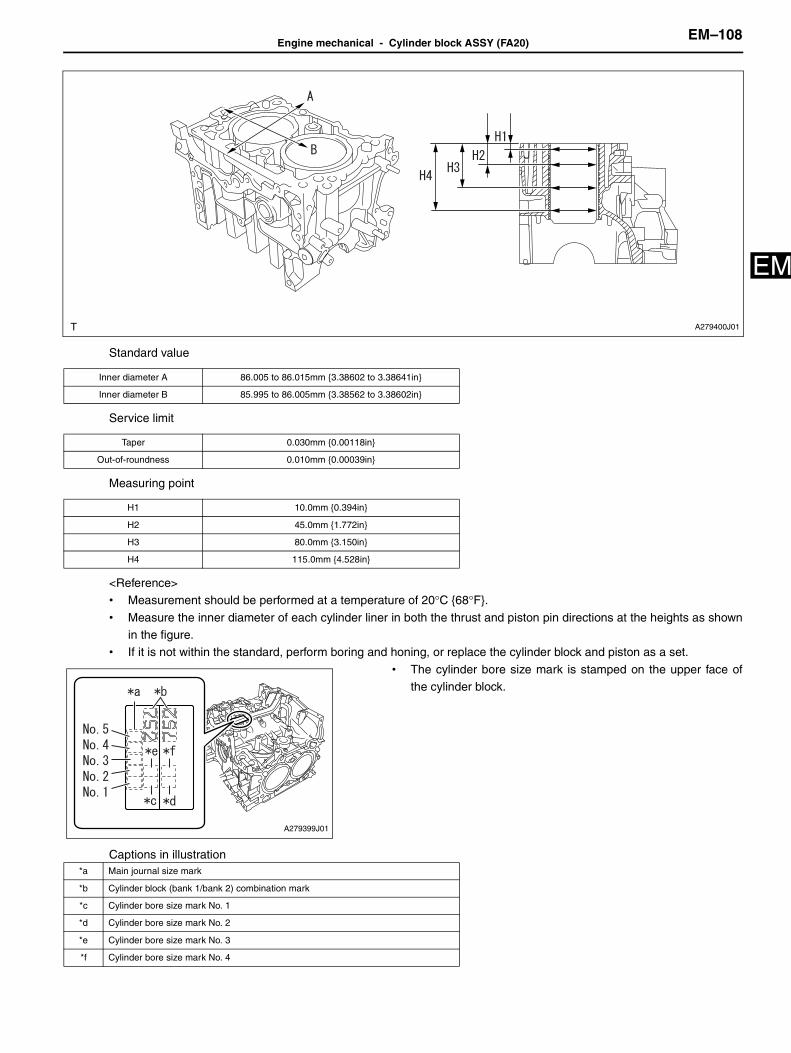
Engine mechanical - Cylinder block ASSY (FA20)EM–108
M
EStandard value
Service limit
Measuring point
<Reference>• Measurement should be performed at a temperature of 20°C {68°F}.
• Measure the inner diameter of each cylinder liner in both the thrust and piston pin directions at the heights as shownin the figure.
• If it is not within the standard, perform boring and honing, or replace the cylinder block and piston as a set.
• The cylinder bore size mark is stamped on the upper face ofthe cylinder block.
Captions in illustration
Inner diameter A 86.005 to 86.015mm {3.38602 to 3.38641in}
Inner diameter B 85.995 to 86.005mm {3.38562 to 3.38602in}
Taper 0.030mm {0.00118in}
Out-of-roundness 0.010mm {0.00039in}
H1 10.0mm {0.394in}
H2 45.0mm {1.772in}
H3 80.0mm {3.150in}
H4 115.0mm {4.528in}
A279400J01
A279399J01
*a Main journal size mark
*b Cylinder block (bank 1/bank 2) combination mark
*c Cylinder bore size mark No. 1
*d Cylinder bore size mark No. 2
*e Cylinder bore size mark No. 3
*f Cylinder bore size mark No. 4

EM–109Engine mechanical - Cylinder block ASSY (FA20)
EM
4. Inspection of piston outer diameter(1) Set a micrometer at 39.4 mm {1.551 in} from the upper face of
piston skirt, and then measure the diameter at a right angle to the
pin hole.Standard value
<Reference>• Measurement should be performed at a temperature of 20°C
{68°F}.• Measure the outer diameter of each piston in thrust direction at
the height as shown in the figure.
• If it is not within the specified value, replace the piston.• Standard sized pistons are classified into two grades, (A) and
(B).These grades should be used as guide lines in selecting a
standard piston.• If the piston is replaced, check the clearance between cylinder
liner and piston and select a suitable sized piston.
5. Inspection of piston oil clearance
(1) Calculate the oil clearance from the inner diameter of cylinder liner and the outer diameter of piston.Standard value: 0.010 to 0.030mm {0.00039 to 0.0018in}<Reference>
• Oil clearance = Cylinder maximum inner dia. - Piston outer dia.• If it is not within the standard, perform boring and honing, or replace the cylinder block and piston as a set.
6. Correction of cylinder liner(1) If any of the inner diameter, taper, out-of-roundness or clearance between cylinder liner and piston is out of standard or if
there is any damage on the cylinder liner, rebore it to replace with an oversize piston.Boring limit: 86.505 mm {3.40570in} (inner diameter of cylinder liner)<Reference>
• When any of the cylinder liner needs reboring, all other cylinder liners must be bored at the same time, and replacedwith oversize pistons.
• If the inner diameter of cylinder liner exceeds the limit after boring and honing, replace the cylinder block and piston
as a set.• Immediately after reboring, the inner diameter of cylinder liner may differ from its real diameter due to temperature
rise.Thus, when measuring the inner diameter of cylinder liner, wait until it has cooled to a temperature of 20°C{68°F}.
7. Inspection of piston with pin(1) Check the piston and piston pin for wear or crack.(2) Check the piston hole snap ring for distortion or wear.
(3) Check the piston ring groove for damage.(4) Check the groove for burr.
Captions in illustration
<Reference>
If the burr is found, remove the burr from groove.
(5) Check that the piston pin can be inserted into the piston with a thumb.
ME-06984
Grade A 85.985 to 85.995mm {3.38523 to 3.38562in}
Grade B 85.975 to 85.985mm {3.38484 to 3.38523in}
0.25mm oversize 86.225 to 86.245mm {3.39468 to 3.39547in}
0.50mm oversize 86.475 to 86.495mm {3.40452 to 3.40531in}
A279402J01
*1 Groove

Engine mechanical - Cylinder block ASSY (FA20)EM–110
M
E<Reference>Inspection should be performed at a temperature of 20°C {68°F}.
8. Inspection of connecting rod small end bushing(1) Check that the connecting rod small end bushing is not damaged.
9. Inspection of piston pin oil clearance
(1) Using a caliper gauge, measure the inner diameter of piston pinhole.<Reference>
• Measurement should be performed at a temperature of 20°C{68°F}.
• Measure the inner diameter of the piston pin hole at the four
locations as shown in the figure, and read the value of mostworn location.
• Record the measured value.
(2) Check the piston pin outer diameter at the position shown in thefigure using a micrometer.<Reference>
• Measurement should be performed at a temperature of 20°C{68°F}.
• Measure the outer diameter of the piston pin at the four
locations as shown in the figure, and read the value of mostworn location.
• Record the measured value.
(3) Using a caliper gauge, measure the inner diameter of connectingrod bushing.
<Reference>• Measurement should be performed at a temperature of 20°C
{68°F}.
• Measure the inner diameter of the connecting rod bushing atthe two locations as shown in the figure, and read the value ofmost worn location.
• Record the measured value.(4) Calculate the clearance between piston and piston pin.
Standard value: 0.004 to 0.008mm {0.00016 to 0.00031in}
<Reference>• Oil clearance = Piston pin hole inner dia. - Piston pin outer dia.• If it is not within the standard, replace the piston and piston pin
as a set.(5) Calculate the clearance between piston pin and connecting rod
bushing.
Standard value: 0.006 to 0.026mm {0.00024 to 0.00102in} <Reference>• Oil clearance = Connecting rod bushing inner dia. - Piston pin
outer dia.• If the clearance between piston pin and connecting rod bushing
is not within the standard, replace the connecting rod and
piston pin as a set.
10. Inspection of piston ring(1) Make sure the piston ring is not broken or damaged.
<Reference>
• If damaged, replace the piston ring.• Use piston ring with same size as piston when replacing piston ring.
A279403
ME-06985
A281040

EM–111Engine mechanical - Cylinder block ASSY (FA20)
EM
11. Inspection of ring closed gap(1) Using the piston, set the piston ring into cylinder liner at a right
angle.
Captions in illustration
<Reference>Press down into the cylinder liner until the ring gets in down to thecrown of the piston.
(2) Measure the closed gap of the piston ring using a thickness gauge.
Standard value
<Reference>
• Measurement should be performed at a temperature of 20°C{68°F}.
• If it is not within the standard value, replace the piston ring.
• Use piston ring with same size as piston when replacing pistonring.
12. Inspection of clearance piston ring and ring groove(1) Fit the piston ring straight into the piston ring groove, then check
the clearance between piston ring and piston using a thicknessgauge.Standard value
<Reference>• Measurement should be performed at a temperature of 20°C
{68°F}.
• Before inspecting the clearance, clean the piston ring grooveand piston ring.
• If it is not within the standard value, replace the piston ring.
• Use piston ring with same size as piston when replacing pistonring.
13. Inspection of connecting rod ASSY(1) Check that the large or small end thrust surface of each connecting rod is not damaged.
(2) Check each connecting rod bearing for scar, peeling, seizure, melting or wear, etc.
ME-06585
*1 Piston ring
A279405
No. 1 0.20 to 0.25mm {0.00784 to 0.00984in}
No. 2 0.60 to 0.70mm {0.02362 to 0.02756in}
Oil 0.10 to 0.35mm {0.00394 to 0.01378in}
A279515
No. 1 0.030 to 0.080mm {0.00118 to 0.00315in}
No. 2 0.030 to 0.070mm {0.00118 to 0.00276in}

Engine mechanical - Cylinder block ASSY (FA20)EM–112
M
E(3) Check for bend using a connecting rod aligner.Limit (per a length of 100 mm {3.937 in}): 0.10mm {0.0039in} <Reference>
• Measurement should be performed at a temperature of 20°C{68°F}.
• If it exceeds the limit, replace the connecting rod.
(4) Check for twist using a connecting rod aligner.Limit (per a length of 100 mm {3.937 in}): 0.10mm {0.0039in} <Reference>
• Measurement should be performed at a temperature of 20°C{68°F}.
• If it exceeds the limit, replace the connecting rod.
14. Inspection of connecting rod thrust clearance
(1) Clean the connecting rod bearing and crank pin and apply engine oil to the crank pin.<*1>(2) With the claw aligned in position, assemble the connecting rod
bearing with the connecting rod and connecting rod cap.
Captions in illustration
ME-06586
ME-06587
A281479J01
*a Claw position
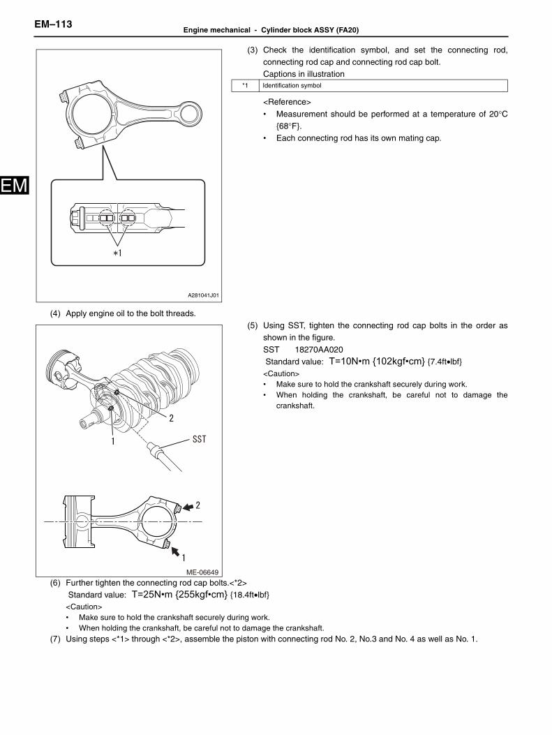
EM–113Engine mechanical - Cylinder block ASSY (FA20)
EM
(3) Check the identification symbol, and set the connecting rod,connecting rod cap and connecting rod cap bolt.Captions in illustration
<Reference>
• Measurement should be performed at a temperature of 20°C{68°F}.
• Each connecting rod has its own mating cap.
(4) Apply engine oil to the bolt threads.(5) Using SST, tighten the connecting rod cap bolts in the order as
shown in the figure.
SST 18270AA020 Standard value: T=10N•m {102kgf•cm} {7.4ft•lbf}<Caution>• Make sure to hold the crankshaft securely during work.• When holding the crankshaft, be careful not to damage the
crankshaft.
(6) Further tighten the connecting rod cap bolts.<*2> Standard value: T=25N•m {255kgf•cm} {18.4ft•lbf}<Caution>• Make sure to hold the crankshaft securely during work.• When holding the crankshaft, be careful not to damage the crankshaft.
(7) Using steps <*1> through <*2>, assemble the piston with connecting rod No. 2, No.3 and No. 4 as well as No. 1.
A281041J01
*1 Identification symbol
ME-06649

Engine mechanical - Cylinder block ASSY (FA20)EM–114
M
E(8) Further-tighten the connecting rod cap bolts No. 1 through No. 4 by92.5° in the order as shown in the figure using SST.SST 18270AA020, 18854AA000<Caution>• Make sure to hold the crankshaft securely during work.• When holding the crankshaft, be careful not to damage the
crankshaft.
(9) Check the thrust clearance of each connecting rod using athickness gauge.Standard value: 0.070 to 0.330mm {0.00276 to 0.01299in}
<Reference>• If it is not within the standard value, replace the connecting rod.• Measure the thrust clearance of each connecting rod at several
points, and replace the connecting rod if there is uneven wear.
15. Inspection of connecting rod bearing oil clearance(1) Remove the connecting rod bearing.<*1>(2) Set the connecting rod bearing to the connecting rod and connecting rod cap.
(3) Place the plastigauge to the axial direction of crankshaft pin, andthen, check the identification symbol, and set the connecting rod,connecting rod cap and connecting rod cap bolt.
Captions in illustration
<Reference>• Measurement should be performed at a temperature of 20°C
{68°F}.
• Each connecting rod has its own mating cap.
(4) Apply engine oil to the bolt threads.
ME-06646
A279519
A281041J01
*1 Identification symbol

EM–115Engine mechanical - Cylinder block ASSY (FA20)
EM
(5) Using SST, tighten the connecting rod cap bolts in the order asshown in the figure.SST 18270AA020
Standard value: T=10N•m {102kgf•cm} {7.4ft•lbf}<Caution>• Do not turn the crankshaft during measuring.• Make sure to hold the crankshaft securely during work.• When holding the crankshaft, be careful not to damage the
crankshaft.
(6) Further tighten the connecting rod cap bolts.<*2> Standard value: T=25N•m {255kgf•cm} {18.4ft•lbf}<Caution>• Do not turn the crankshaft during measuring.• Make sure to hold the crankshaft securely during work.• When holding the crankshaft, be careful not to damage the crankshaft.
(7) Using steps <*1> through <*2>, assemble the piston with connecting rod No. 2, No.3 and No. 4 as well as No. 1.(8) Further-tighten the connecting rod cap bolts No. 1 through No. 4 by
92.5° in the order as shown in the figure using SST.SST 18270AA020, 18854AA000<Caution>• Do not turn the crankshaft during measuring.• Make sure to hold the crankshaft securely during work.• When holding the crankshaft, be careful not to damage the
crankshaft.
(9) Remove the bearing cap to measure the widest point of the
plastigauge.Standard value: 0.025 to 0.055mm {0.00098 to 0.00217in}<Caution>Completely remove the plastigauge after measuring.<Reference>• If it is not within the standard value, replace the connecting rod
bearing.• Measure the outer diameter of crank pin using micrometer, and
select the suitable size connecting rod bearing when replacing
the connecting rod bearing.Standard value
ME-06649
ME-06646
A279521
Bearing Bearing size (Thickness at center) Outer diameter of crank pin
Standard 1.492 to 1.508 mm (0.05874 to 0.05937 in.) 49.976 to 50.000 mm (1.96756 to 1.96850 in.)
0.03 mm (0.0012 in.) Undersize 1.511 to 1.515 mm (0.05949 to 0.05965 in.) 49.946 to 49.970 mm (1.96637 to 1.96732 in.)
0.05 mm (0.0020 in.) Undersize 1.521 to 1.525 mm (0.05988 to 0.06004 in.) 49.926 to 49.950 mm (1.96559 to 1.96653 in.)
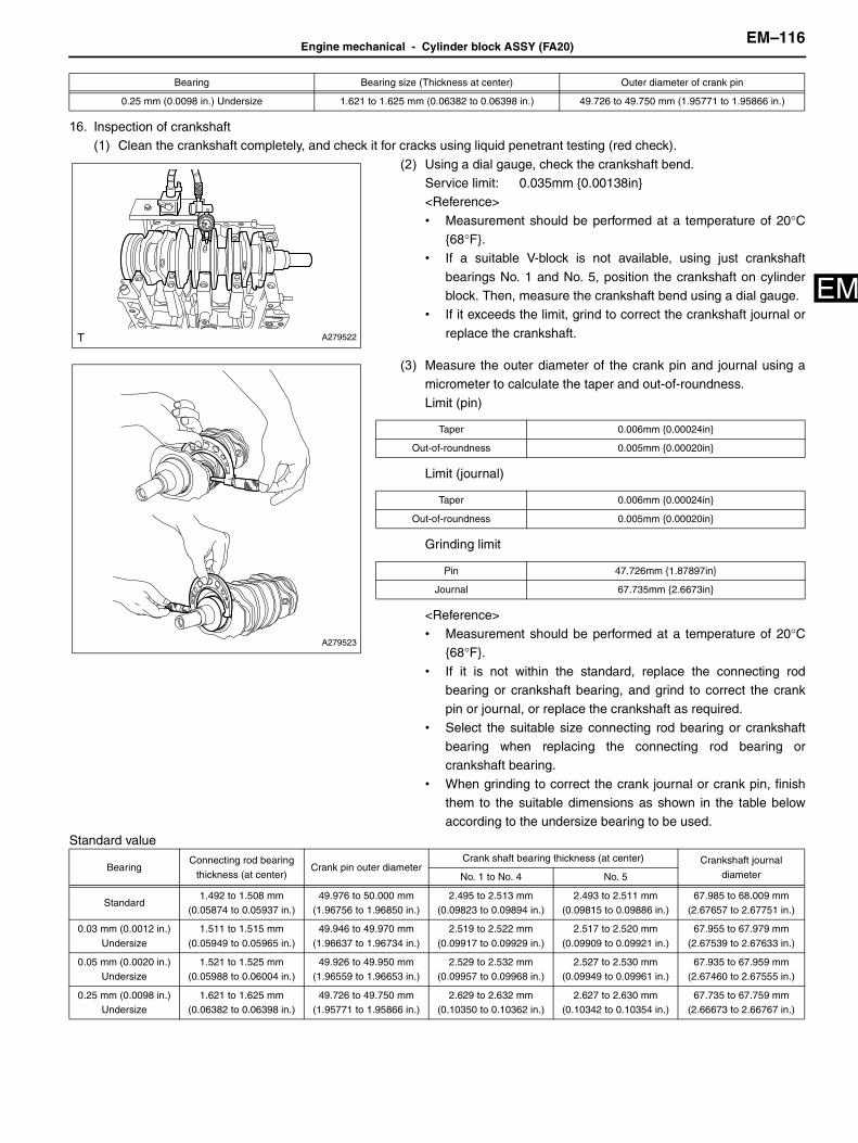
Engine mechanical - Cylinder block ASSY (FA20)EM–116
M
E16. Inspection of crankshaft(1) Clean the crankshaft completely, and check it for cracks using liquid penetrant testing (red check).
(2) Using a dial gauge, check the crankshaft bend.Service limit: 0.035mm {0.00138in}<Reference>
• Measurement should be performed at a temperature of 20°C{68°F}.
• If a suitable V-block is not available, using just crankshaft
bearings No. 1 and No. 5, position the crankshaft on cylinderblock. Then, measure the crankshaft bend using a dial gauge.
• If it exceeds the limit, grind to correct the crankshaft journal or
replace the crankshaft.
(3) Measure the outer diameter of the crank pin and journal using amicrometer to calculate the taper and out-of-roundness.
Limit (pin)
Limit (journal)
Grinding limit
<Reference>• Measurement should be performed at a temperature of 20°C
{68°F}.
• If it is not within the standard, replace the connecting rodbearing or crankshaft bearing, and grind to correct the crankpin or journal, or replace the crankshaft as required.
• Select the suitable size connecting rod bearing or crankshaftbearing when replacing the connecting rod bearing orcrankshaft bearing.
• When grinding to correct the crank journal or crank pin, finishthem to the suitable dimensions as shown in the table belowaccording to the undersize bearing to be used.
Standard value
0.25 mm (0.0098 in.) Undersize 1.621 to 1.625 mm (0.06382 to 0.06398 in.) 49.726 to 49.750 mm (1.95771 to 1.95866 in.)
Bearing Bearing size (Thickness at center) Outer diameter of crank pin
A279522
A279523
Taper 0.006mm {0.00024in}
Out-of-roundness 0.005mm {0.00020in}
Taper 0.006mm {0.00024in}
Out-of-roundness 0.005mm {0.00020in}
Pin 47.726mm {1.87897in}
Journal 67.735mm {2.6673in}
BearingConnecting rod bearing
thickness (at center)Crank pin outer diameter
Crank shaft bearing thickness (at center) Crankshaft journal
diameterNo. 1 to No. 4 No. 5
Standard1.492 to 1.508 mm
(0.05874 to 0.05937 in.)49.976 to 50.000 mm
(1.96756 to 1.96850 in.)2.495 to 2.513 mm
(0.09823 to 0.09894 in.)2.493 to 2.511 mm
(0.09815 to 0.09886 in.)67.985 to 68.009 mm
(2.67657 to 2.67751 in.)
0.03 mm (0.0012 in.)
Undersize
1.511 to 1.515 mm
(0.05949 to 0.05965 in.)
49.946 to 49.970 mm
(1.96637 to 1.96734 in.)
2.519 to 2.522 mm
(0.09917 to 0.09929 in.)
2.517 to 2.520 mm
(0.09909 to 0.09921 in.)
67.955 to 67.979 mm
(2.67539 to 2.67633 in.)
0.05 mm (0.0020 in.) Undersize
1.521 to 1.525 mm (0.05988 to 0.06004 in.)
49.926 to 49.950 mm (1.96559 to 1.96653 in.)
2.529 to 2.532 mm (0.09957 to 0.09968 in.)
2.527 to 2.530 mm (0.09949 to 0.09961 in.)
67.935 to 67.959 mm (2.67460 to 2.67555 in.)
0.25 mm (0.0098 in.) Undersize
1.621 to 1.625 mm (0.06382 to 0.06398 in.)
49.726 to 49.750 mm (1.95771 to 1.95866 in.)
2.629 to 2.632 mm (0.10350 to 0.10362 in.)
2.627 to 2.630 mm (0.10342 to 0.10354 in.)
67.735 to 67.759 mm (2.66673 to 2.66767 in.)

EM–117Engine mechanical - Cylinder block ASSY (FA20)
EM
17. Inspection of crankshaft bearing(1) Check the crankshaft bearing for scar, peeling, seizure, melting or wear, etc.
18. Inspection of crankshaft thrust clearance(1) Use a thickness gauge to check the thrust clearance of crankshaft
at crankshaft bearing No. 5.Standard value: 0.130 to 0.308mm {0.00512 to 0.01213in}<Reference>
If it is not within the standard value, replace crankshaft bearingNo. 5.
19. Inspection of crankshaft oil clearance(1) Remove the gasket from cylinder block.
(2) Clean each crankshaft bearing and crankshaft journal.(3) Set each crankshaft bearing to the cylinder block.
Captions in illustration
<Caution>• Be careful not to scratch the mating surface of cylinder block
during work.• Because journal bearings No. 1 and No. 3 differ from No. 2 and No.
4, confirm at assembly.
(4) Set the crankshaft to the cylinder block (bank 2 side).(5) Set a plastigauge to the axial direction of the crankshaft journal.(6) Set the cylinder block (bank 1 side) to the cylinder block (bank 2 side).
(7) Apply engine oil to the washers and cylinder block mounting bolt threads.<Caution>To prevent mixture of engine oil into the water jacket, do not apply a large amount.
A279524
A279378J01
*1 Crankshaft bearing No. 1, No. 3 (with groove)
*2 Crankshaft bearing No. 2, No. 4 (without groove)
*3 Crankshaft bearing No. 5
*a Bank 1
*b Bank 2

Engine mechanical - Cylinder block ASSY (FA20)EM–118
M
E(8) Tighten the ten mounting bolts in the order as shown in the figure. Standard value: T=35N•m {357kgf•cm} {25.8ft•lbf}<Caution>When tightening the mounting bolts, hold the cylinder block (bank 2side) while not holding the cylinder block (bank 1 side) to ensure thejoint accuracy of the cylinder block.
(9) Loosen the ten mounting bolts by 180° in the order as shown in thefigure.<Caution>When loosening the mounting bolts, hold the cylinder block (bank 2side) while not holding the cylinder block (bank 1 side) to ensure thejoint accuracy of the cylinder block.
(10)Tighten the ten mounting bolts in the order as shown in the figure. Standard value: T=35N•m {357kgf•cm} {25.8ft•lbf}<Caution>When tightening the mounting bolts, hold the cylinder block (bank 2side) while not holding the cylinder block (bank 1 side) to ensure thejoint accuracy of the cylinder block.
(11) Loosen the four mounting bolts by 180° in the order as shown inthe figure.<Caution>When loosening the mounting bolts, hold the cylinder block (bank 2side) while not holding the cylinder block (bank 1 side) to ensure thejoint accuracy of the cylinder block.
(12)Tighten the four mounting bolts in the order as shown in the figure. Standard value: T=17N•m {173kgf•cm} {12.5ft•lbf}<Caution>When tightening the mounting bolts, hold the cylinder block (bank 2side) while not holding the cylinder block (bank 1 side) to ensure thejoint accuracy of the cylinder block.
A279376J02
A279376J01
A279376J02
A283331J01
A283331J02

EM–119Engine mechanical - Cylinder block ASSY (FA20)
EM
(13)Further-tighten the four mounting bolts by 60° in the order asshown in the figure using SST.SST 18854AA000
Captions in illustration
<Caution>When tightening the mounting bolts, hold the cylinder block (bank 2side) while not holding the cylinder block (bank 1 side) to ensure thejoint accuracy of the cylinder block.<Reference>As necessary, attach the temporary bolt to fix SST.
(14)Loosen the six mounting bolts by 180° in the order as shown in thefigure.<Caution>When loosening the mounting bolts, hold the cylinder block (bank 2side) while not holding the cylinder block (bank 1 side) to ensure thejoint accuracy of the cylinder block.
(15)Tighten the six mounting bolts in the order as shown in the figure. Standard value: T=17N•m {173kgf•cm} {12.5ft•lbf}<Caution>When tightening the mounting bolts, hold the cylinder block (bank 2side) while not holding the cylinder block (bank 1 side) to ensure thejoint accuracy of the cylinder block.
(16)Further-tighten the six mounting bolts by 60° in the order as shownin the figure using SST.SST 18854AA000
Captions in illustration
<Caution>When tightening the mounting bolts, hold the cylinder block (bank 2side) while not holding the cylinder block (bank 1 side) to ensure thejoint accuracy of the cylinder block.<Reference>As necessary, attach the temporary bolt to fix SST.
(17)Loosen the ten cylinder block mounting bolts in the order as shownin the figure.
(18)Remove the 10 bolts to remove the cylinder block (bank 1 side).
ME-06645
*a temporary bolt
A283332J01
A283332J02
ME-06647
*a temporary bolt
A279376J01

Engine mechanical - Cylinder block ASSY (FA20)EM–120
M
E<Caution>Lift the cylinder block (bank 1 side) slightly, and make sure that the crankshaft is remaining in the cylinder block (bank 2 side).Ifthe cylinder block (bank 1 side) is lifted without care, the crankshaft may be lifted along and fall off from the cylinder block (bank1 side).
(19)Measure the widest point of the plastigauge.Standard value: 0.013 to 0.031mm {0.00051 to 0.00122 in}<Caution>Completely remove the plastigauge after measuring.<Reference>
• If it is not within the standard, replace the crankshaft bearing,and grind to correct the crankshaft journal or replace thecrankshaft as required.
• Select the crankshaft bearing of suitable size according to thetable below when replacing crankshaft bearing.
• When grinding to correct the crankshaft journal, finish them to
the suitable dimensions as shown in the table below accordingto the undersize bearing to be used.
Standard value
ASSEMBLY1. Installation of cylinder block tight plug No. 1
<Caution>• During the work, stabilize the cylinder block by placing it on a wooden piece wrapped with cloth etc, in this case be careful not to
contact the knock pin with the wooden piece.• Be careful not to scratch the mating surface of cylinder block during work.
(1) Apply THREE BOND 1105 to the threaded portions of three
cylinder block tight plug No. 1s and install to cylinder block (bank 1side and bank 2 side).Captions in illustration
Standard value: T=37N•m {377kgf•cm} {27.3ft•lbf}<Caution>Before applying liquid gasket, degrease the thread holes of thecylinder block and main gallery plug.
A279521
BearingConnecting rod bearing
thickness (at center)Crank pin outer diameter
Crank shaft bearing thickness (at center) Crankshaft journal diameterNo. 1 to No. 4 No. 5
Standard1.492 to 1.508 mm
(0.05874 to 0.05937 in.)
49.976 to 50.000 mm
(1.96756 to 1.96850 in.)
2.495 to 2.513 mm
(0.09823 to 0.09894 in.)
2.493 to 2.511 mm
(0.09815 to 0.09886 in.)
67.985 to 68.009 mm
(2.67657 to 2.67751 in.)
0.03 mm (0.0012 in.) Undersize
1.511 to 1.515 mm (0.05949 to 0.05965 in.)
49.946 to 49.970 mm (1.96637 to 1.96734 in.)
2.519 to 2.522 mm (0.09917 to 0.09929 in.)
2.517 to 2.520 mm (0.09909 to 0.09921 in.)
67.955 to 67.979 mm (2.67539 to 2.67633 in.)
0.05 mm (0.0020 in.) Undersize
1.521 to 1.525 mm (0.05988 to 0.06004 in.)
49.926 to 49.950 mm (1.96559 to 1.96653 in.)
2.529 to 2.532 mm (0.09957 to 0.09968 in.)
2.527 to 2.530 mm (0.09949 to 0.09961 in.)
67.935 to 67.959 mm (2.67460 to 2.67555 in.)
0.25 mm (0.0098 in.)
Undersize
1.621 to 1.625 mm
(0.06382 to 0.06398 in.)
49.726 to 49.750 mm
(1.95771 to 1.95866 in.)
2.629 to 2.632 mm
(0.10350 to 0.10362 in.)
2.627 to 2.630 mm
(0.10342 to 0.10354 in.)
67.735 to 67.759 mm
(2.66673 to 2.66767 in.)
A279611J01
*a Bank 1
*b Bank 2

EM–121Engine mechanical - Cylinder block ASSY (FA20)
EM
2. Installation of crankshaft sensor holder ASSY(1) Install the crankshaft sensor holder ASSY to the cylinder block
(bank 2 side) with two bolts.
Standard value: T=6.4N•m {65kgf•cm} {4.7ft•lbf}
3. Installation of cylinder block plate(1) Install the cylinder block plate to the cylinder block (bank 2 side)
with five bolts.
Standard value: T=6.4N•m {65kgf•cm} {4.7ft•lbf}
4. Installation of oil separator cover(1) Apply THREE BOND 1217G to the mating surface of the new oil
separator cover.
Captions in illustration
<Caution>• Clean and degrease the fitting surface.• Install within 5 min. after applying liquid gasket.
(2) Tighten seven bolts in order as shown in the figure, and install theoil separator cover to the cylinder block (bank 1 side). Standard value: T=6.4N•m {65kgf•cm} {4.7ft•lbf}
5. Installation of O-ring(1) Install a new O-ring to the cylinder block (bank 2 side).
A278796
A279368
A279367J01
*a Dia. 3.0 to 5.0mm {0.138 to 0.197in}
A279366
A279377

Engine mechanical - Cylinder block ASSY (FA20)EM–122
M
E6. Installation of crankshaft bearing(1) Apply engine oil to the ten crankshaft bearing and install to cylinder
block (bank 1 side and bank 2 side).
Captions in illustration
<Caution>• Be careful not to scratch the mating surface of cylinder block
during work.• Because journal bearings No. 1 and No. 3 differ from No. 2 and No.
4, confirm at assembly.
7. Installation of crankshaft(1) Apply engine oil to the crankshaft journal, and set to the cylinder
block (bank 2 side).
8. Installation of cylinder block SUB-ASSY (bank 1 side)(1) Apply THREE BOND 1217G to the mating surface of the cylinder block (bank 1 side) as shown in the figure.
Captions in illustration
A279378J01
*1 Crankshaft bearing No. 1, No. 3 (with groove)
*2 Crankshaft bearing No. 2, No. 4 (without groove)
*3 Crankshaft bearing No. 5
*a Bank 1
*b Bank 2
A279379
*a Dia. 3.5 to 4.5mm {0.138 to 0.177in} *b Dia. 0.5 to 1.5mm {0.0197 to 0.0591in}
*c Range A-A *d Within 1.0mm {0.039in}
*e Dia. 2.7 to 3.7mm {0.106 to 0.146in} *f Dia. 3.5 to 4.5mm {0.138 to 0.177in}
ME-06986

EM–123Engine mechanical - Cylinder block ASSY (FA20)
EM
<Caution>• Do not let the gasket overflow to the oil passage and crankshaft bearing portions, because the engine seizure may result.• Clean and degrease the fitting surface.• Install within 5 min. after applying liquid gasket.
(2) Install the cylinder block (bank 1 side) to the cylinder block (bank 2 side).(3) Apply engine oil to the washers and cylinder block mounting bolt threads.
<Caution>To prevent mixture of engine oil into the water jacket, do not apply a large amount.
(4) Tighten the ten mounting bolts in the order as shown in the figure.
Standard value: T=35N•m {357kgf•cm} {25.8ft•lbf}<Caution>When tightening the mounting bolts, hold the cylinder block (bank 2side) while not holding the cylinder block (bank 1 side) to ensure thejoint accuracy of the cylinder block.
(5) Loosen the ten mounting bolts by 180° in the order as shown in the
figure.<Caution>When loosening the mounting bolts, hold the cylinder block (bank 2side) while not holding the cylinder block (bank 1 side) to ensure thejoint accuracy of the cylinder block.
(6) Tighten the ten mounting bolts in the order as shown in the figure.
Standard value: T=35N•m {357kgf•cm} {25.8ft•lbf}<Caution>When tightening the mounting bolts, hold the cylinder block (bank 2side) while not holding the cylinder block (bank 1 side) to ensure thejoint accuracy of the cylinder block.
(7) Loosen the four bolts by 180° in the order as shown in the figure.
<Caution>When loosening the mounting bolts, hold the cylinder block (bank 2side) while not holding the cylinder block (bank 1 side) to ensure thejoint accuracy of the cylinder block.
*g 2.0mm {0.079in} *h Groove
A279376J02
A279376J01
A279376J02
A283331J01
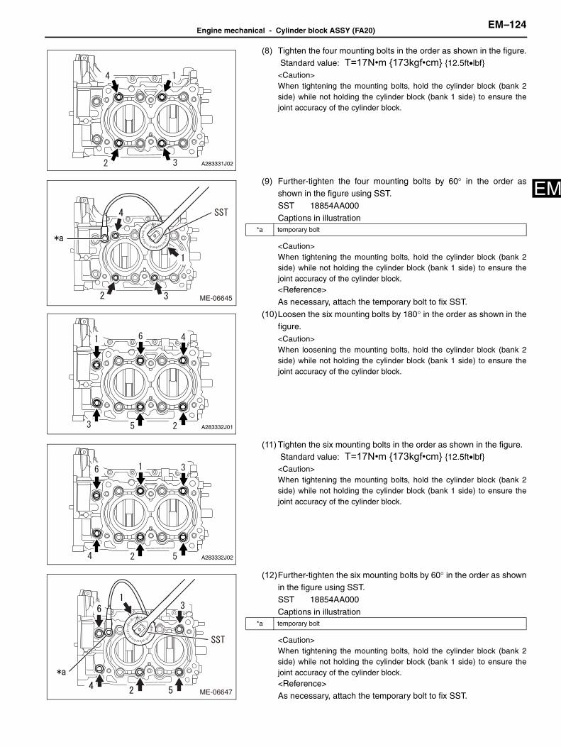
Engine mechanical - Cylinder block ASSY (FA20)EM–124
M
E(8) Tighten the four mounting bolts in the order as shown in the figure. Standard value: T=17N•m {173kgf•cm} {12.5ft•lbf}<Caution>When tightening the mounting bolts, hold the cylinder block (bank 2side) while not holding the cylinder block (bank 1 side) to ensure thejoint accuracy of the cylinder block.
(9) Further-tighten the four mounting bolts by 60° in the order asshown in the figure using SST.SST 18854AA000
Captions in illustration
<Caution>When tightening the mounting bolts, hold the cylinder block (bank 2side) while not holding the cylinder block (bank 1 side) to ensure thejoint accuracy of the cylinder block.<Reference>As necessary, attach the temporary bolt to fix SST.
(10)Loosen the six mounting bolts by 180° in the order as shown in thefigure.<Caution>When loosening the mounting bolts, hold the cylinder block (bank 2side) while not holding the cylinder block (bank 1 side) to ensure thejoint accuracy of the cylinder block.
(11) Tighten the six mounting bolts in the order as shown in the figure. Standard value: T=17N•m {173kgf•cm} {12.5ft•lbf}<Caution>When tightening the mounting bolts, hold the cylinder block (bank 2side) while not holding the cylinder block (bank 1 side) to ensure thejoint accuracy of the cylinder block.
(12)Further-tighten the six mounting bolts by 60° in the order as shownin the figure using SST.SST 18854AA000
Captions in illustration
<Caution>When tightening the mounting bolts, hold the cylinder block (bank 2side) while not holding the cylinder block (bank 1 side) to ensure thejoint accuracy of the cylinder block.<Reference>As necessary, attach the temporary bolt to fix SST.
A283331J02
ME-06645
*a temporary bolt
A283332J01
A283332J02
ME-06647
*a temporary bolt

EM–125Engine mechanical - Cylinder block ASSY (FA20)
EM
(13) Install the five bolts shown in the figure. Standard value: T=25N•m {255kgf•cm} {18.4ft•lbf}<Reference>
After tightening, if the gasket is squeezed out in the seal surfacearea of the oil pan upper, completely remove any gasket that issqueezed out.However, gasket in the groove should not be
removed.
9. Installation of engine rear oil seal(1) Apply a little coat of engine oil to the inside and outside of the new engine rear oil seal.
(2) Using SST, strike in the engine rear oil seal equally flush with the
end surface of the cylinder block.SST 18671AA020, 18657AA030<Caution>• Do not hammer in the engine rear oil seal obliquely.• Wipe off the oil attached to the crankshaft.• Do not hammer in the engine rear oil seal too deep.<Reference>The strike amount of the engine rear oil seal is allowed within 0 to -1 mm {0 to -0.039 in} from the end surface of the cylinder block.
10. Installation of cylinder block SUB-ASSY(1) Mount the cylinder block SUB-ASSY onto the engine stand.
11. Installation of piston with pin
(1) Install the piston pin hole snap ring to one side of the piston usinga screwdriver wrapped with protective tape.Captions in illustration
<Reference>
• Make sure the piston pin hole snap ring is firmly inserted intothe groove.
• After installing the piston pin hole snap ring, turn the piston pin
hole snap ring so that the end and cutout portion of the holesnap ring do not match.
Captions in illustration
A279375
ME-06589
A281475J01
*1 Protective tape
A279396J01
*1 Piston pin hole snap ring
*a OK
*b NG
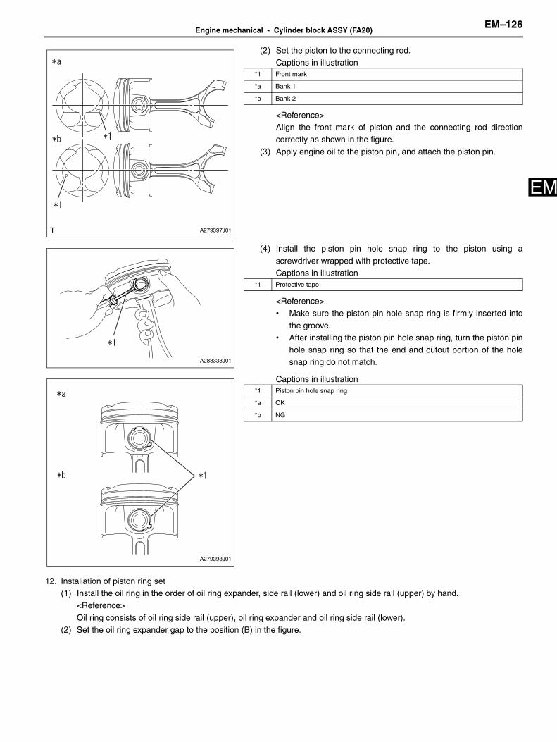
Engine mechanical - Cylinder block ASSY (FA20)EM–126
M
E(2) Set the piston to the connecting rod.Captions in illustration
<Reference>Align the front mark of piston and the connecting rod directioncorrectly as shown in the figure.
(3) Apply engine oil to the piston pin, and attach the piston pin.
(4) Install the piston pin hole snap ring to the piston using a
screwdriver wrapped with protective tape.Captions in illustration
<Reference>• Make sure the piston pin hole snap ring is firmly inserted into
the groove.• After installing the piston pin hole snap ring, turn the piston pin
hole snap ring so that the end and cutout portion of the hole
snap ring do not match.
Captions in illustration
12. Installation of piston ring set(1) Install the oil ring in the order of oil ring expander, side rail (lower) and oil ring side rail (upper) by hand.
<Reference>
Oil ring consists of oil ring side rail (upper), oil ring expander and oil ring side rail (lower).(2) Set the oil ring expander gap to the position (B) in the figure.
A279397J01
*1 Front mark
*a Bank 1
*b Bank 2
A283333J01
*1 Protective tape
A279398J01
*1 Piston pin hole snap ring
*a OK
*b NG

EM–127Engine mechanical - Cylinder block ASSY (FA20)
EM
(3) Engage the lower turn stopper of the oil ring side rail (lower) in theoil notch of the coated piston skirt cutout at the position (A) in thefigure and engage the upper turn stopper to the oil ring expander.
Captions in illustration
(4) Align the oil ring side rail (upper) gap to position (C) (0 to 20°) in the figure and engage the upper turn stopper to the oilring expander.
(5) Using a piston ring tool, install compression ring No. 2 and then, compression ring No. 1in numerical order with astamped mark upward.
(6) Set the gap of compression ring No. 1 to the position (A) or (B) in
the figure.<Reference>Either (A) or (B) is good for compression ring No. 1 if it points in the
piston pin direction.
(7) Set the gap of compression ring No. 2 to the position (A) or (B), 180° opposite side of compression ring No. 1, in thefigure.
(8) Check that the positions of piston ring and oil ring gap are properly adjusted.
13. Installation of piston with connecting rod
(1) Move the engine stand to face the oil pan side of the cylinder block upward.(2) With the claw aligned in position, assemble the connecting rod
bearing with the connecting rod and connecting rod cap.<*1>
Captions in illustration
(3) Check that the positions of piston ring and oil ring gap are properly adjusted.(4) Apply engine oil to the outer circumference of each piston, crank pin, and in the cylinder block.
ME-07036ME-07036
*1 Front mark
*2 Oil ring side rail (lower)
*3 Oil ring expander
*4 Cutout portion
*a 0 to 20°
A279612J01
A281479J01
*a Claw position

Engine mechanical - Cylinder block ASSY (FA20)EM–128
M
E(5) Turn the crankshaft so that the crankshaft pin position comes toTDC.Captions in illustration
(6) Compress the piston ring using piston ring compressor, and insert
the piston with connecting rod into the cylinder block by tapping thepiston crown using the handle of a plastic hammer etc.<Caution>• Be careful not to damage the cylinder liner and crankshaft pin by
the connecting rod large end.• Do not apply strong impact when inserting the piston with
connecting rod to prevent connecting rod bearing from falling off.<Reference>
Face the piston front mark towards the front of the engine.
(7) Apply engine oil to the connecting rod cap seat and the connecting rod cap bolt threads.(8) Turn the crankshaft so that the crank pin and the large end of
connecting rod are positioned as shown in the figure, while
pressing the piston crown, and then install the connecting rod capusing the connecting rod cap bolt.Captions in illustration
A279392J01
*1 Crankshaft pin
A279393
A279394J01
*1 Connecting rod
*2 Crankshaft pin

EM–129Engine mechanical - Cylinder block ASSY (FA20)
EM
<Reference>• Each connecting rod has its own mating cap.Make sure that
they are assembled correctly by checking their identification
symbols.Captions in illustration
• Use a new connecting rod cap bolt.• When installing piston with connecting rod No. 1 and No. 3,
turn the crankshaft counter-clockwise, on the other hand, wheninstalling the piston with connecting rod No. 2 and No. 4, turnthe crankshaft clockwise.
(9) Using SST, tighten the two connecting rod cap bolts in the order asshown in the figure.SST 18270AA020
Captions in illustration
Standard value: T=10N•m {102kgf•cm} {7.4ft•lbf}
(10)Further-tighten the two bolts in the same order.<*2> Standard value: T=25N•m {255kgf•cm} {18.4ft•lbf}
(11) Using steps <*1> through <*2>, assemble the piston with connecting rod No. 2, No.3 and No. 4 as well as No. 1.
A281041J01
*1 Identification symbol
ME-06650
*a Cylinder No. 1, No. 4
*b Cylinder No. 2, No. 3

Engine mechanical - Cylinder block ASSY (FA20)EM–130
M
E(12)Further-tighten the connecting rod cap bolts No. 1 through No. 4 by92.5° in the order as shown in the figure using SST.SST 18270AA020, 18854AA000
Captions in illustration
<Reference>
As necessary, attach the temporary bolt to fix SST.
(13)Make sure that the crankshaft turns smoothly.ME-06651
*a Cylinder No. 1, No. 4
*b Cylinder No. 2, No. 3
*c temporary bolt

EM–131Engine mechanical - Cylinder block ASSY (FA20)
EM
CO
ENGINE/HYBRID SYSTEM
COOLING
WATER PUMP (FA20)INSPECTION . . . . . . . . . . . . . . . . . . . . . . . . . . . . . . . . . . . . . . . . . . . . . . CO-1

CO–1Cooling - Water pump (FA20)
CO
Engine/hybrid systemCoolingWATER PUMP (FA20)
INSPECTION1. Inspection of engine water pump ASSY
(1) Make sure that the bearing has no noise and catch.<Reference>If noise or catch is noted, replace the engine water pump ASSY.
(2) Make sure the impeller is not abnormally deformed or damaged.<Reference>If the impeller is abnormally deformed or damaged, replace the
engine water pump ASSY.
CO-03080