coe 205 - faculty.kfupm.edu.safaculty.kfupm.edu.sa/coe/talalkh/docs/02_coe205_part2.doc · web...
TRANSCRIPT

COE 205Introduction to
Computer Organization and
Assembly Language
1 of 85

Advanced Arithmetic
Advanced Arithmetic ..................................................................................................................................6Introduction ..........................................................................................................................................................6
ADD, SUB :............................................................................................................................................................6Adding and Subtracting Integers:........................................................................................................................................6
ADC, SBB...........................................................................................................................................................7Adding and Subtracting in Multiple Registers:...................................................................................................7Adding and Subtracting on 64 bit Operands:......................................................................................................................8
DAA and DAS Instructions ...............................................................................................................................9DAA operation:...................................................................................................................................................................9
MUL, IMUL........................................................................................................................................................10Using Multiplication Instructions:.....................................................................................................................................10
DIV, IDIV............................................................................................................................................................11Using Division Instructions:.....................................................................................................................................11
Divide Overflow and Sign Extension..............................................................................................13The CBW and CWD instructions:.....................................................................................................................................13Divide Overflow:...............................................................................................................................................................13
Preparing Dividend.......................................................................................................................................................13
Conclusion .........................................................................................................................................................13
Bit Manipulation Instructions ...............................................................................................................15LOGICAL INSTRUCTION..............................................................................................................................15
Effects on Status Flag........................................................................................................................................................15The Truth tables.................................................................................................................................................................15The Usage..........................................................................................................................................................................16
Changing a letter to its opposite case............................................................................................................................17Converting an ASCII digit to a Decimal digit and vice versa:.....................................................................................17Examining selected bits in the Destination Operand....................................................................................................18Determine whether a general-purpose register is equal to zero....................................................................................18Clearing a general-purpose register operand or a memory operand to zero.................................................................18
Shift Instructions ...............................................................................................................................................18EFFECT of SHIFT INSTRUCTIONS on FLAGS............................................................................................................19Logical Shift Instruction....................................................................................................................................................19
Left shift (SHL).............................................................................................................................................................19Right Shift (SHR).........................................................................................................................................................21
Shift arithmetic Instructions..............................................................................................................................................21Double Precision Shift Instructions...................................................................................................................................21
Rotate Instructions.............................................................................................................................................21General syntax format........................................................................................................................................................22ROL (Rotate Left) Instruction...........................................................................................................................................22ROR (Rotate Right) Instruction.........................................................................................................................................22RCL (Rotate through Carry Left) Instruction....................................................................................................................22RCR (Rotate through Carry right) Instruction...................................................................................................................22
Flow Control Instructions ......................................................................................................................24Introduction ........................................................................................................................................................24
Conditional Jump Instructions..........................................................................................................................25High Level Conditional Structures....................................................................................................................................25
2 of 85
Advanced Arithmetic
Unconditional Jump Instruction: JMP ..........................................................................................................25Relative Address...........................................................................................................................................................26
CMP Instruction ...............................................................................................................................................27
Conditional Jump Instructions..........................................................................................................................28Addressing Modes.............................................................................................................................................................29
Single-Flag Based Jump Instructions...............................................................................................................29Unsigned Conditional Jump Instructions ........................................................................................................................30Signed Conditional Jump Instructions ............................................................................................................................31
Loop Instructions.......................................................................................................................................32LOOPZ/LOOPE and LOOPNZ/LOOPNE Instructions....................................................................................................32The JCXZ instruction........................................................................................................................................................33
IF-Then and IF-THEN-ELSE Structures........................................................................................................34IF Structure with Logical Operators..................................................................................................................................35
CASE Statement.................................................................................................................................................35
WHILE Structure...............................................................................................................................................36
Repeat-Until Structure.......................................................................................................................................37
Indirect Jump Example ...................................................................................................................................37
Stack and Procedures ...............................................................................................................................39Objectives............................................................................................................................................................39
The Stack ............................................................................................................................................................39Pentium Stack Instructions and Directives........................................................................................................................40Stack Usage.......................................................................................................................................................................40Pentium Advanced Stack Instructions...............................................................................................................................40
Procedures ...........................................................................................................................................................42How does a Procedure work? ..........................................................................................................................................42Assembler Directives for Procedures................................................................................................................................43
Defining Subroutine......................................................................................................................................................43Preserving Registers ...................................................................................................................................................44
Parameter Passing..............................................................................................................................................................44Using general purpose registers....................................................................................................................................45Using global (static) variables......................................................................................................................................45Stack Method: Passing Arguments on the Stack..........................................................................................................46Naming Conventions....................................................................................................................................................46The C Calling Convention............................................................................................................................................47
.........................................................................................................48The STDCALL Calling Conventions...........................................................................................................................48
3 of 85

Advanced Arithmetic
The Pascal Calling Convention.....................................................................................................................................48Local Variables..................................................................................................................................................................49
Macros and Conditional Assembly ........................................................................................................50Macro Definition and Invocation ....................................................................................................................50
Position of Macro Definition.............................................................................................................................................51Macros versus Procedures ...............................................................................................................................................51Parameter passing..............................................................................................................................................................52
Types of parameters......................................................................................................................................................52Invocation mechanism..................................................................................................................................................52When are macros better................................................................................................................................................53
Labels in Macros ..............................................................................................................................................54Labels in Procedures.....................................................................................................................................................54Conflicts with Local Labels..........................................................................................................................................55
Macro Expansion in the .LST File ..................................................................................................................................55List Control Directives ....................................................................................................................................................56
Macro list control directives.........................................................................................................................................56Comments in Macros....................................................................................................................................................56Assembly errors during macro expansion.....................................................................................................................57Nested Macros ..............................................................................................................................................................57Recursive Macros..........................................................................................................................................................58Macro Library .............................................................................................................................................................58Position of INCLUDE Statement..................................................................................................................................58Examples of Useful Macros..........................................................................................................................................58
Using a Macro Library.......................................................................................................................................................59
Macro Operators................................................................................................................................................59Substitute Operator (&) ...................................................................................................................................................60Literal-Text String Operator (<>) ...................................................................................................................................61Literal-Character Operator (!) .........................................................................................................................................61
Successive Single Quotes.............................................................................................................................................62Expression Evaluate Operator (%) ..................................................................................................................................62Repeat Block Directives ..................................................................................................................................................62
REPT Macro Invocation...............................................................................................................................................63WHILE Directive .......................................................................................................................................................64
IRP Directive ....................................................................................................................................................64IRPC Directive ................................................................................................................................................................65
Conditional Assembly .............................................................................................................................67Introduction.........................................................................................................................................................67
IF and IFE Directives .......................................................................................................................................67IFDEF and IFNDEF Directives ..................................................................................................................................69
IFB and IFNB Directives .................................................................................................................................69String MSG Declaration...............................................................................................................................................70
IFIDN and IFDIF Directives ...........................................................................................................................71Directives Overhead......................................................................................................................................................71
String Handling Instructions ...................................................................................................................72Objectives:...........................................................................................................................................................72
Introduction ......................................................................................................................................................72
Move String Instructions .................................................................................................................................73
4 of 85
Advanced Arithmetic
The MOVSB instruction...............................................................................................................................................74The MOVSW instruction..............................................................................................................................................74The MOVSD instruction...............................................................................................................................................74
REP Prefix.........................................................................................................................................................................75
Compare String Instructions ..........................................................................................................................76The CMPSB Instruction................................................................................................................................................77The CMPSW Instruction...............................................................................................................................................77The CMPSD Instruction...............................................................................................................................................77
REPE/REPZ Prefix............................................................................................................................................................78REPNE/REPNZ Prefix......................................................................................................................................................78
Scan String Instructions ..................................................................................................................................79The SCASB Instruction................................................................................................................................................80The SCASW Instruction...............................................................................................................................................80The SCASD Instruction................................................................................................................................................80
Store String Instructions .................................................................................................................................81The STOSB instruction.................................................................................................................................................82The STOSW instruction................................................................................................................................................82The STOSD instruction.................................................................................................................................................82
Load String Instructions ..................................................................................................................................83The LODSB instruction................................................................................................................................................83The LODSW instruction...............................................................................................................................................84The LODSD instruction................................................................................................................................................84
5 of 85

Advanced Arithmetic
6 of 85
Advanced Arithmetic
Advanced Arithmetic
Introduction
This unit deals with the arithmetic instructions used with the 8086 processor. These are as follows:
ADD and ADC used for adding
INC used for incrementing,
SUB and SBB used for subtracting
DEC used for decrementing
All these instructions operate on values in single registers, memory or constants. They can also be combined to
handle larger values that require two registers for storage.
The 8086 family of processors uses different multiplication and division instructions for signed and unsigned
integers.
IMUL for signed multiplication
IMUL for signed division
Multiplication and division instructions have also special requirements depending on the size of the operands and
the processor the code runs on.
ADD, SUB :
Adding and Subtracting Integers:
The ADD, INC (Increment), SUB, and DEC (Decrement) instructions operate on 8 and 16-bit values on the 8086
& 80286 processors, and on 8-, 16-, and 32-bit values on the 80386/486 processors. They can be combined with
the ADC and SBB instructions to work on 32-bit values on the 8086 and 64-bit values on the 80386/486
processors.
These instructions have two requirements:
1. If there are two operands, only one operand can be a memory operand.
2. If there are two operands, both must be the same size.
To meet the second requirement, the PTR operator can be used to force an operand to the size required.
For example, if Buffer is an array of bytes and BX points to an element of the array, you can add a word from
Buffer with:
add ax, WORD PTR Buffer[bx] ; Add word from byte array
7 of 85
Advanced Arithmetic
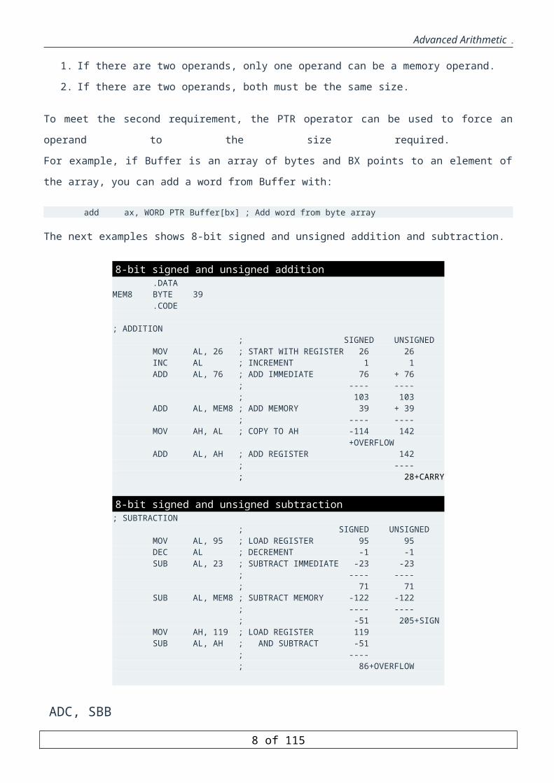
The next examples shows 8-bit signed and unsigned addition and subtraction.
8-bit signed and unsigned addition .DATAMEM8 BYTE 39 .CODE ; ADDITION ; SIGNED UNSIGNED MOV AL, 26 ; START WITH REGISTER 26 26 INC AL ; INCREMENT 1 1 ADD AL, 76 ; ADD IMMEDIATE 76 + 76 ; ---- ---- ; 103 103 ADD AL, MEM8 ; ADD MEMORY 39 + 39 ; ---- ---- MOV AH, AL ; COPY TO AH -114 142 +OVERFLOW ADD AL, AH ; ADD REGISTER 142 ; ---- ; 28+CARRY
8-bit signed and unsigned subtraction; SUBTRACTION ; SIGNED UNSIGNED MOV AL, 95 ; LOAD REGISTER 95 95 DEC AL ; DECREMENT -1 -1 SUB AL, 23 ; SUBTRACT IMMEDIATE -23 -23 ; ---- ---- ; 71 71 SUB AL, MEM8 ; SUBTRACT MEMORY -122 -122 ; ---- ---- ; -51 205+SIGN MOV AH, 119 ; LOAD REGISTER 119 SUB AL, AH ; AND SUBTRACT -51 ; ---- ; 86+OVERFLOW
ADC, SBB
Adding and Subtracting in Multiple Registers:Numbers larger than the register size on your processor can be added and subtracted with the ADC (Add with
Carry) and SBB (Subtract with Borrow) instructions. These instructions work as follows:
ADC Dest, Source ; Dest = Dest + Source + Carry FlagSBB Dest, Source ; Dest = Dest - Source - Carry Flag
If the operations prior to an ADC or SBB instruction do not set the carry flag, these instructions are identical to
ADD and SUB. While operating on large values in more than one register, ADD and SUB are used for the least
significant part of the number and ADC or SBB for the most significant part.
8 of 85

Advanced Arithmetic
The following example illustrates multiple-register addition and subtraction.
Use of ADC and SBB Instructionson the 8086 Processor .DATAmem32 DWORD 316423mem32a DWORD 316423mem32b DWORD 156739 .CODE . . .; Addition mov ax, 43981 ; Load immediate 43981 sub dx, dx ; into DX:AX add ax, WORD PTR mem32[0] ; Add to both + 316423 adc dx, WORD PTR mem32[2] ; memory words ------ ; Result in DX:AX 360404; Subtraction mov ax, WORD PTR mem32a[0] ; Load mem32 316423 mov dx, WORD PTR mem32a[2] ; into DX:AX sub ax, WORD PTR mem32b[0] ; Subtract low - 156739 sbb dx, WORD PTR mem32b[2] ; then high ------ ; Result in DX:AX 159684
Adding and Subtracting on 64 bit Operands:
This technique can also be used with 64-bit operands on the 80386/486 processors. For 32-bit registers on the
80386/486 processors, only two steps are necessary. If your program needs to be assembled for more than one
processor, you can assemble the statements conditionally, as shown in this example:
Use of ADC and SBB Instructionson 80386/486 processors .DATAmem32 DWORD 316423mem32a DWORD 316423mem32b DWORD 156739p386 TEXTEQU (@Cpu AND 08h) .CODE . . .; Addition IF p386 mov eax, 43981 ; Load immediate add eax, mem32 ; Result in EAX ELSE . . ; do steps in previous example . ENDIF; Subtraction IF p386 mov eax, mem32a ; Load memory sub eax, mem32b ; Result in EAX ELSE . . ; do steps in previous example . ENDIF
9 of 85

Advanced Arithmetic
Since the status of the carry flag affects the results of calculations with ADC and SBB, be sure to turn off the
carry flag with the CLC (Clear Carry Flag) instruction or use ADD or SUB for the first calculation, when
appropriate.
DAA and DAS Instructions
The DAA (Decimal Adjust after Addition) instruction allows addition of numbers represented in 8-bit packed
BCD code. It is used immediately after normal addition instruction operating on BCD codes. This instruction
assumes the AL register as the source and the destination, and hence it requires no operand.
The effect of DAS (Decimal Adjust after Subtraction) instruction is similar to that of DAA, except that it is used
after a subtraction instruction. For example in the following program, that NUM1 and NUM2 are decimal
numbers coded in BCD format, the result should be 61
DAA Instructions.MODEL SMALL.STACK 200.DATA NUM1 DB 27H NUM2 DB 35H.CODE.STARTUP MOV AL, NUM1 ;load AX with number NUM1 ADD AL, NUM2 ;AL = AL + NUM2 i.e. AL = 5CH = 92 in decimal ;The expected result is 62 in decimal DAA ; AL = 62.EXITEND
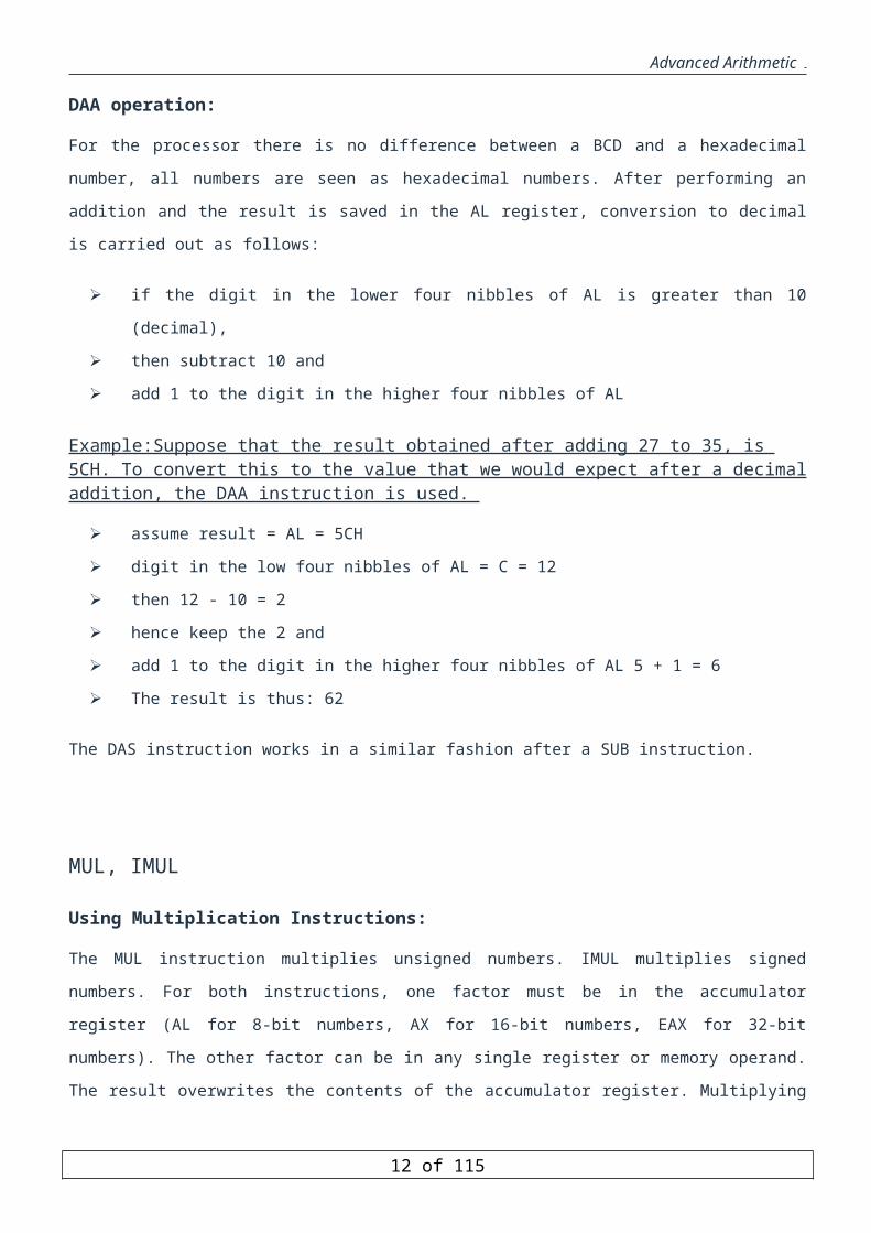
DAA operation:
For the processor there is no difference between a BCD and a hexadecimal number, all numbers are seen as
hexadecimal numbers. After performing an addition and the result is saved in the AL register, conversion to
decimal is carried out as follows:
if the digit in the lower four nibbles of AL is greater than 10 (decimal),
then subtract 10 and
add 1 to the digit in the higher four nibbles of AL
Example:Suppose that the result obtained after adding 27 to 35, is 5CH. To convert this to the value that we would expect after a decimal addition, the DAA instruction is used.
assume result = AL = 5CH
digit in the low four nibbles of AL = C = 12
then 12 - 10 = 2
hence keep the 2 and
add 1 to the digit in the higher four nibbles of AL 5 + 1 = 6
The result is thus: 62
10 of 85

Advanced Arithmetic
The DAS instruction works in a similar fashion after a SUB instruction.
MUL, IMUL
Using Multiplication Instructions:
The MUL instruction multiplies unsigned numbers. IMUL multiplies signed numbers. For both instructions, one
factor must be in the accumulator register (AL for 8-bit numbers, AX for 16-bit numbers, EAX for 32-bit
numbers). The other factor can be in any single register or memory operand. The result overwrites the contents of
the accumulator register. Multiplying two 8-bit numbers produces a 16-bit result returned in AX. Multiplying two
16-bit operands yields a 32-bit result in DX:AX.
The 80386/486 processor handles 64-bit products in the same way in the EDX:EAX pair. \
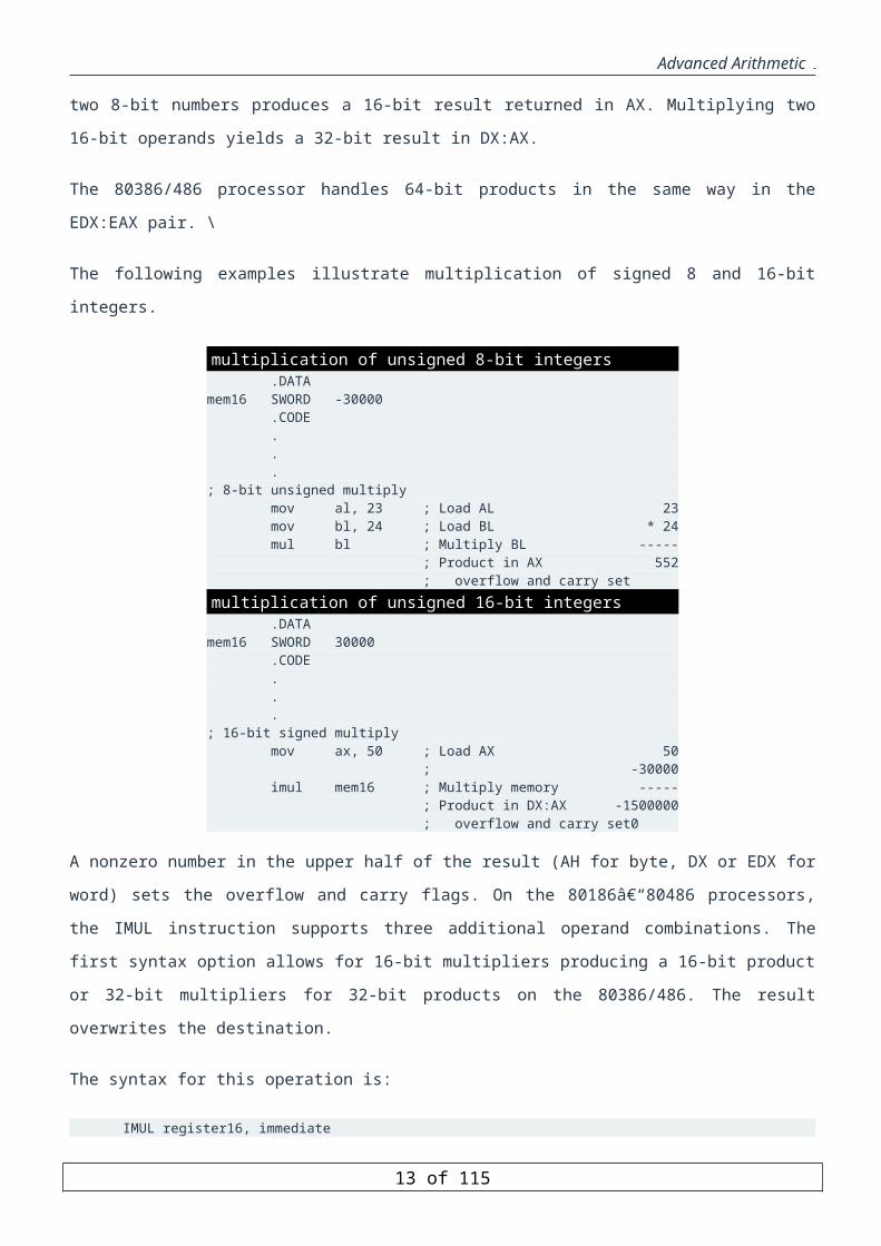
The following examples illustrate multiplication of signed 8 and 16-bit integers.
multiplication of unsigned 8-bit integers .DATAmem16 SWORD -30000 .CODE . . .; 8-bit unsigned multiply mov al, 23 ; Load AL 23 mov bl, 24 ; Load BL * 24 mul bl ; Multiply BL ----- ; Product in AX 552 ; overflow and carry setmultiplication of unsigned 16-bit integers .DATAmem16 SWORD 30000 .CODE . . .; 16-bit signed multiply mov ax, 50 ; Load AX 50 ; -30000 imul mem16 ; Multiply memory ----- ; Product in DX:AX -1500000 ; overflow and carry set0
A nonzero number in the upper half of the result (AH for byte, DX or EDX for word) sets the overflow and carry
flags. On the 80186–80486 processors, the IMUL instruction supports three additional operand combinations.
The first syntax option allows for 16-bit multipliers producing a 16-bit product or 32-bit multipliers for 32-bit
products on the 80386/486. The result overwrites the destination.
The syntax for this operation is:
IMUL register16, immediate
11 of 85
Advanced Arithmetic
The second syntax option specifies three operands for IMUL. The first operand must be a 16-bit register operand,
the second a 16-bit memory (or register) operand, and the third a 16-bit immediate operand. IMUL multiplies the
memory (or register) and immediate operands and stores the product in the register operand with this syntax:
IMUL register16,{ memory16 | register16}, immediate
For the 80386/486 only, a third option for IMUL allows an additional operand for multiplication of a register
value by a register or memory value.
The syntax is:
IMUL register,{register | memory}
The destination can be any 16-bit or 32-bit register. The source must be the same size as the destination.
In all of these options, products too large to fit in 16 or 32 bits set the overflow and carry flags. The following
examples show these three options for IMUL.
multiplication of signed 32-bit integers
imul dx, 456 ; Multiply DX times 456 on 80186-80486 imul ax, [bx],6 ; Multiply the value pointed to by BX ; by 6 and put the result in AX
imul dx, ax ; Multiply DX times AX on 80386 imul ax, [bx] ; Multiply AX by the value pointed to ; by BX on 80386
The IMUL instruction with multiple operands can be used for either signed or unsigned multiplication, since the
16-bit product is the same in either case. To get a 32-bit result, you must use the single-operand version of MUL
or IMUL.
multiplication of signed 16-bit integers .DATAmem16 SWORD -30000 .CODE . . .; 16-bit signed multiply mov ax, 50 ; Load AX 50 ; -30000 imul mem16 ; Multiply memory ----- ; Product in DX:AX -1500000 ; overflow and carry set
DIV, IDIV
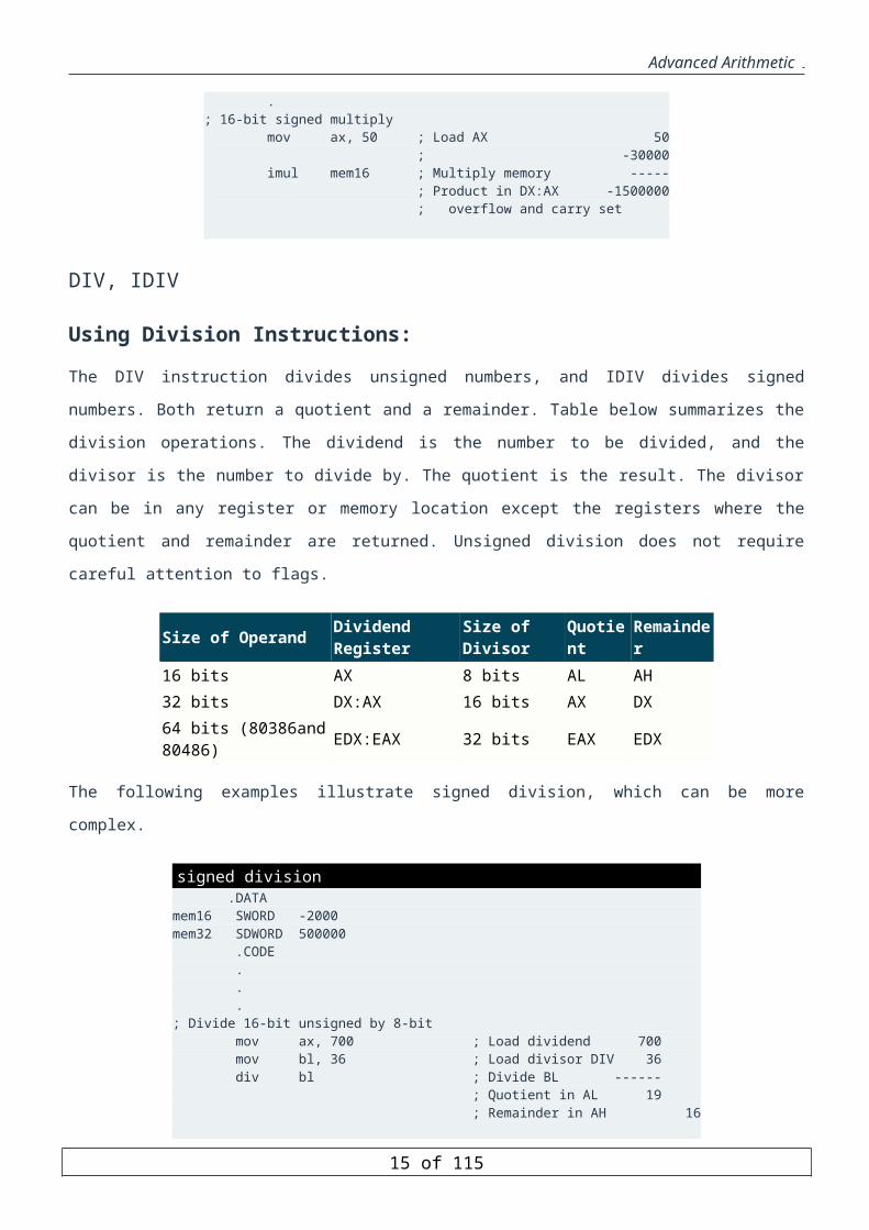
Using Division Instructions:The DIV instruction divides unsigned numbers, and IDIV divides signed numbers. Both return a quotient and a
remainder. Table below summarizes the division operations. The dividend is the number to be divided, and the
12 of 85
Advanced Arithmetic
divisor is the number to divide by. The quotient is the result. The divisor can be in any register or memory
location except the registers where the quotient and remainder are returned. Unsigned division does not require
careful attention to flags.
Size of Operand Dividend Register Size of Divisor Quotient Remainder 16 bits AX 8 bits AL AH 32 bits DX:AX 16 bits AX DX 64 bits (80386and 80486) EDX:EAX 32 bits EAX EDX
The following examples illustrate signed division, which can be more complex.
signed division .DATAmem16 SWORD -2000mem32 SDWORD 500000 .CODE . . .; Divide 16-bit unsigned by 8-bit mov ax, 700 ; Load dividend 700 mov bl, 36 ; Load divisor DIV 36 div bl ; Divide BL ------ ; Quotient in AL 19 ; Remainder in AH 16
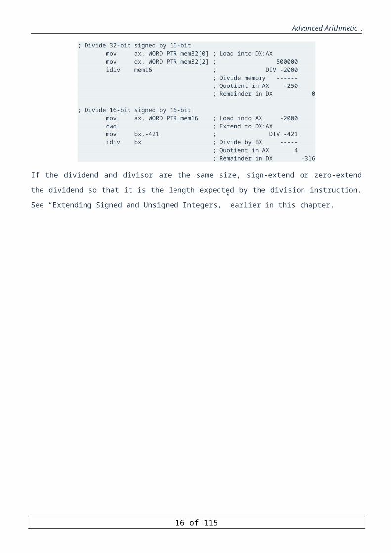
; Divide 32-bit signed by 16-bit mov ax, WORD PTR mem32[0] ; Load into DX:AX mov dx, WORD PTR mem32[2] ; 500000 idiv mem16 ; DIV -2000 ; Divide memory ------ ; Quotient in AX -250 ; Remainder in DX 0
; Divide 16-bit signed by 16-bit mov ax, WORD PTR mem16 ; Load into AX -2000 cwd ; Extend to DX:AX mov bx,-421 ; DIV -421 idiv bx ; Divide by BX ----- ; Quotient in AX 4 ; Remainder in DX -316
If the dividend and divisor are the same size, sign-extend or zero-extend the dividend so that it is the length
expected by the division instruction. See “Extending Signed and Unsigned Integers,” earlier in this chapter.
13 of 85

Advanced Arithmetic
Divide Overflow and Sign Extension
The CBW and CWD instructions:
CBW and CWD are two instructions used to facilitate division of 8 and 16 bit signed numbers. Since division
requires a double-width dividend, CBW converts an 8-bit signed number (in AL) to a word. The MSB of the AL
register is duplicated into AH register. Similarly, CWD converts a 16-bit signed number to a 32-bit signed number
(DX,AX). Here the MSB of the AX register is duplicated into AX register.
Divide Overflow:
Overfow occurs when the result of a division does not fit in a byte if the dividend is a word, and in a word if the
dividend is a double word. Such an overflow terminates the program with "Divide Overflow" message! This
needs to be anticipated and hence can be avoided.
Overflow occurs if:
Byte form: AH>=divisor
Word form: DX>=divisor
Preparing Dividend
To avoid overflow, the dividend has to be prepared as follows. To divide a word in AX by a word, AX must be
converted to a doubleword in DX:AX.
If signed:
CWD (called sign-extension)
If unsigned:
MOV DX,0
To divide a word in AL by a byte, AL must be converted to a word in AX.
If signed:
CBW (these do not affect Flags)
If unsigned:
MOV AH,0
Conclusion
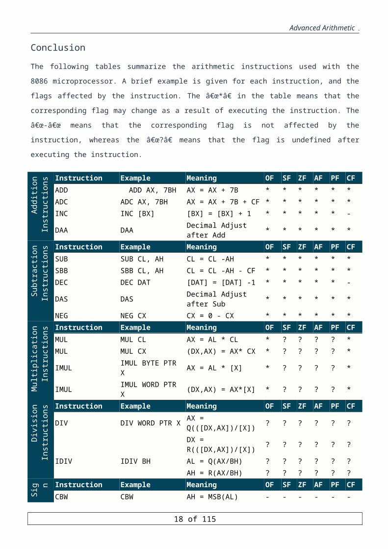
The following tables summarize the arithmetic instructions used with the 8086 microprocessor. A brief example is
given for each instruction, and the flags affected by the instruction. The “*†in the table means that the
corresponding flag may change as a result of executing the instruction. The “-“ means that the
corresponding flag is not affected by the instruction, whereas the “?†means that the flag is undefined after
executing the instruction.
14 of 85
Advanced Arithmetic A
dditi
on
Inst
ruct
ions Instruction Example Meaning OF SF ZF AF PF CF
ADD ADD AX, 7BH AX = AX + 7B * * * * * * ADC ADC AX, 7BH AX = AX + 7B + CF * * * * * * INC INC [BX] [BX] = [BX] + 1 * * * * * - DAA DAA Decimal Adjust after Add * * * * * *
Subt
ract
ion
Inst
ruct
ions Instruction Example Meaning OF SF ZF AF PF CF
SUB SUB CL, AH CL = CL -AH * * * * * * SBB SBB CL, AH CL = CL -AH - CF * * * * * * DEC DEC DAT [DAT] = [DAT] -1 * * * * * - DAS DAS Decimal Adjust after Sub * * * * * * NEG NEG CX CX = 0 - CX * * * * * *
Mul
tiplic
atio n
Inst
ruct
ions Instruction Example Meaning OF SF ZF AF PF CF
MUL MUL CL AX = AL * CL * ? ? ? ? * MUL MUL CX (DX,AX) = AX* CX * ? ? ? ? * IMUL IMUL BYTE PTR X AX = AL * [X] * ? ? ? ? * IMUL IMUL WORD PTR X (DX,AX) = AX*[X] * ? ? ? ? *
Div
isio
n In
stru
ctio
ns Instruction Example Meaning OF SF ZF AF PF CF DIV DIV WORD PTR X AX = Q(([DX,AX])/[X]) ? ? ? ? ? ?
DX = R(([DX,AX])/[X]) ? ? ? ? ? ? IDIV IDIV BH AL = Q(AX/BH) ? ? ? ? ? ?
AH = R(AX/BH) ? ? ? ? ? ?
Sign
Ex
tens
io n Instruction Example Meaning OF SF ZF AF PF CF CBW CBW AH = MSB(AL) - - - - - -
CWD CWD DX = MSB(AX) - - - - - -
15 of 85
Advanced Arithmetic
Bit Manipulation Instructions
LOGICAL INSTRUCTION
Bitwise Logical instructions are the most primitive operations needed by every computer architecture. At a
minimum, an architecture could provide a NAND operations, since all other logical functions can be derived from
NAND operations. These logical operations are semantically different to what is known as in most of high level
programming language. The difference lies down at the fact that bitwise logical operations are performed at bit-
by-bit basis. Pentium provides five logical instructions.
AND destination, source OR destination, source XOR destination, source TEST destination, source NOT destination
All logical instructions need two operands except NOT instructions which is a unary. The result of the operation
is stored in the Destination, which must be a general register or a memory location. The Source may be an
immediate value, register, or memory location. The Destination and Source CANNOT both be memory locations.
The Destination and Source must be of the same size (8-, 16-. 32-bit). All logic instructions, except TEST, modify
the Destination operand. The TEST instruction does not modify any of its operands; however it affects the flags
similar to the AND instruction. All logical instructions, except NOT, affect the status flags.
Effects on Status Flag
Since logical instructions operate on a bit-by-bit basis, no carry or overflow is generated.
Except NOT, all logical instructions clear carry flag (CF) and overflow flag (OF).
AF is undefined
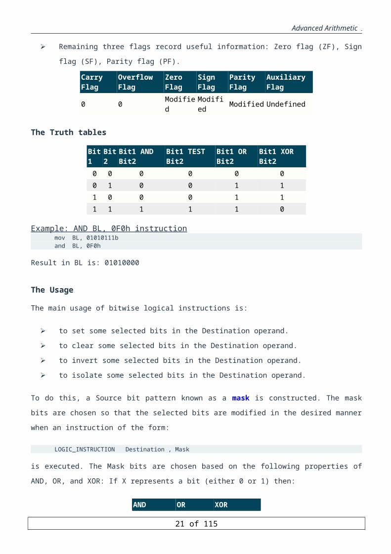
Remaining three flags record useful information: Zero flag (ZF), Sign flag (SF), Parity flag (PF).
Carry Flag Overflow Flag Zero Flag Sign Flag Parity Flag Auxiliary Flag 0 0 Modified Modified Modified Undefined
The Truth tables
Bit1 Bit2 Bit1 AND Bit2 Bit1 TEST Bit2 Bit1 OR Bit2 Bit1 XOR Bit2 0 0 0 0 0 00 1 0 0 1 11 0 0 0 1 11 1 1 1 1 0
Example: AND BL, 0F0h instructionmov BL, 01010111b and BL, 0F0h
Result in BL is: 01010000
16 of 85

Advanced Arithmetic
The Usage
The main usage of bitwise logical instructions is:
to set some selected bits in the Destination operand.
to clear some selected bits in the Destination operand.
to invert some selected bits in the Destination operand.
to isolate some selected bits in the Destination operand.
To do this, a Source bit pattern known as a mask is constructed. The mask bits are chosen so that the selected bits
are modified in the desired manner when an instruction of the form:
LOGIC_INSTRUCTION Destination , Mask
is executed. The Mask bits are chosen based on the following properties of AND, OR, and XOR: If X represents a
bit (either 0 or 1) then:
AND OR XOR X AND 0 = 0 X OR 0 = X X XOR 0 = X X AND 1 = X X OR 1 = 1 X XOR 1 =
The AND instruction can be used to CLEAR specific Destination bits while preserving the others. A
zero mask bit clears the corresponding Destination bit; a one mask bit preserves the corresponding
destination bit.
The OR instruction can be used to SET specific destination bits while preserving the others. A one mask
bit sets the corresponding destination bit; a zero mask bit preserves the corresponding destination bit.
The XOR instruction can be used to INVERT specific Destination bits while preserving the others. A
one mask bit inverts the corresponding Destination bit; a zero mask bit preserves the corresponding
Destination bit.
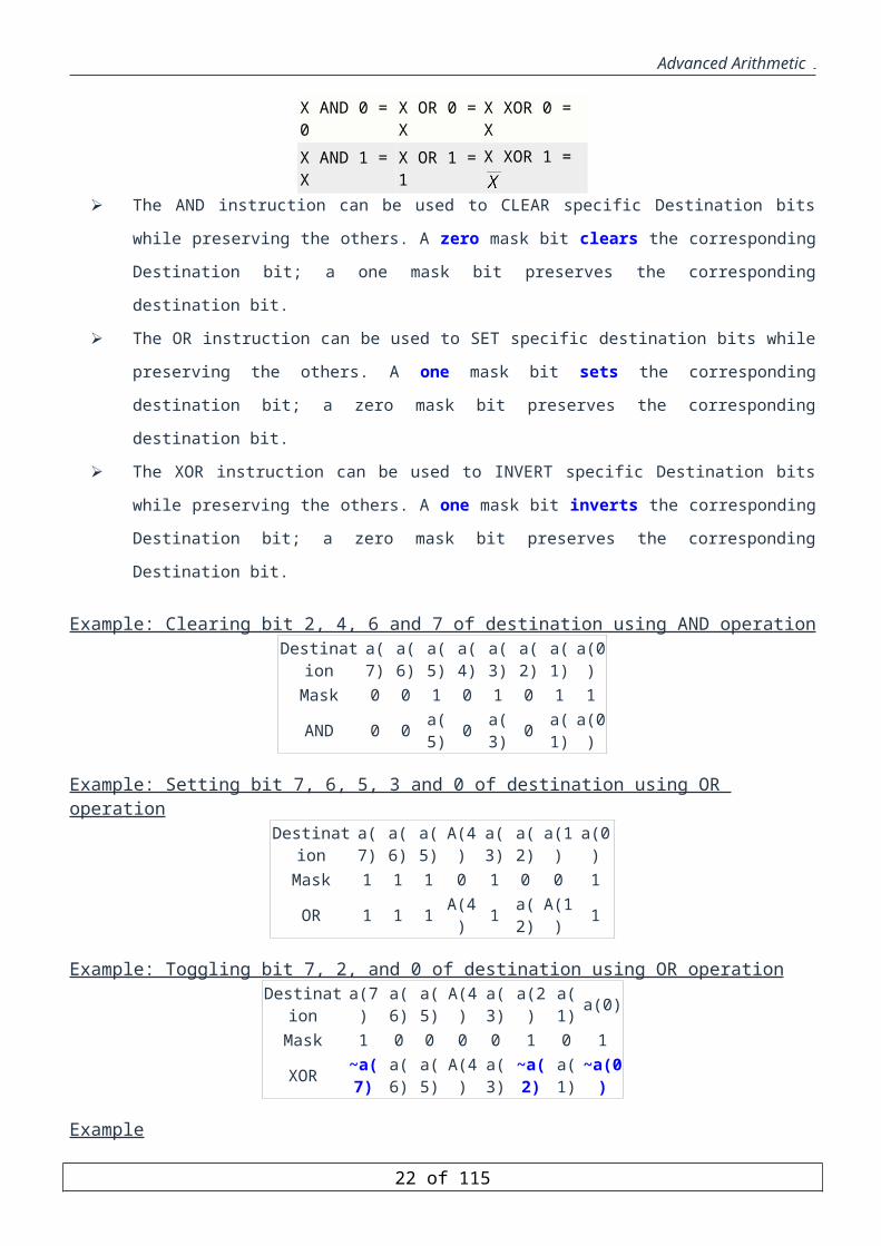
Example: Clearing bit 2, 4, 6 and 7 of destination using AND operationDestination a(7) a(6) a(5) a(4) a(3) a(2) a(1) a(0)
Mask 0 0 1 0 1 0 1 1AND 0 0 a(5) 0 a(3) 0 a(1) a(0)
Example: Setting bit 7, 6, 5, 3 and 0 of destination using OR operationDestination a(7) a(6) a(5) A(4) a(3) a(2) a(1) a(0)
Mask 1 1 1 0 1 0 0 1OR 1 1 1 A(4) 1 a(2) A(1) 1
Example: Toggling bit 7, 2, and 0 of destination using OR operationDestination a(7) a(6) a(5) A(4) a(3) a(2) a(1) a(0)
Mask 1 0 0 0 0 1 0 1XOR ~a(7) a(6) a(5) A(4) a(3) ~a(2) a(1) ~a(0)
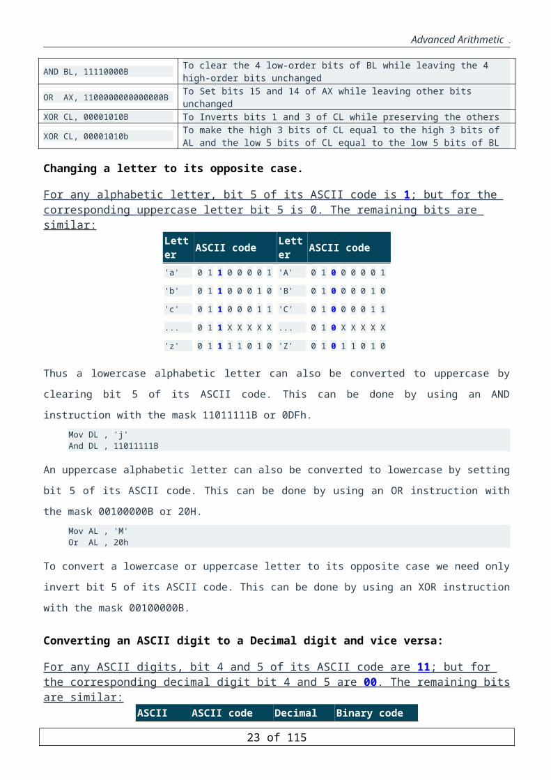
ExampleAND BL, 11110000B To clear the 4 low-order bits of BL while leaving the 4 high-order bits unchanged
17 of 85
Advanced Arithmetic
OR AX, 1100000000000000B To Set bits 15 and 14 of AX while leaving other bits unchangedXOR CL, 00001010B To Inverts bits 1 and 3 of CL while preserving the others
XOR CL, 00001010b To make the high 3 bits of CL equal to the high 3 bits of AL and the low 5 bits of CL equal to the low 5 bits of BL
Changing a letter to its opposite case.
For any alphabetic letter, bit 5 of its ASCII code is 1 ; but for the corresponding uppercase letter bit 5 is 0. The remaining bits are similar:
Letter ASCII code Letter ASCII code 'a' 0 1 1 0 0 0 0 1 'A' 0 1 0 0 0 0 0 1
'b' 0 1 1 0 0 0 1 0 'B' 0 1 0 0 0 0 1 0
'c' 0 1 1 0 0 0 1 1 'C' 0 1 0 0 0 0 1 1
... 0 1 1 X X X X X ... 0 1 0 X X X X X
'z' 0 1 1 1 1 0 1 0 'Z' 0 1 0 1 1 0 1 0
Thus a lowercase alphabetic letter can also be converted to uppercase by clearing bit 5 of its ASCII code. This can
be done by using an AND instruction with the mask 11011111B or 0DFh. Mov DL , 'j' And DL , 11011111B
An uppercase alphabetic letter can also be converted to lowercase by setting bit 5 of its ASCII code. This can be
done by using an OR instruction with the mask 00100000B or 20H.Mov AL , 'M' Or AL , 20h
To convert a lowercase or uppercase letter to its opposite case we need only invert bit 5 of its ASCII code. This
can be done by using an XOR instruction with the mask 00100000B.
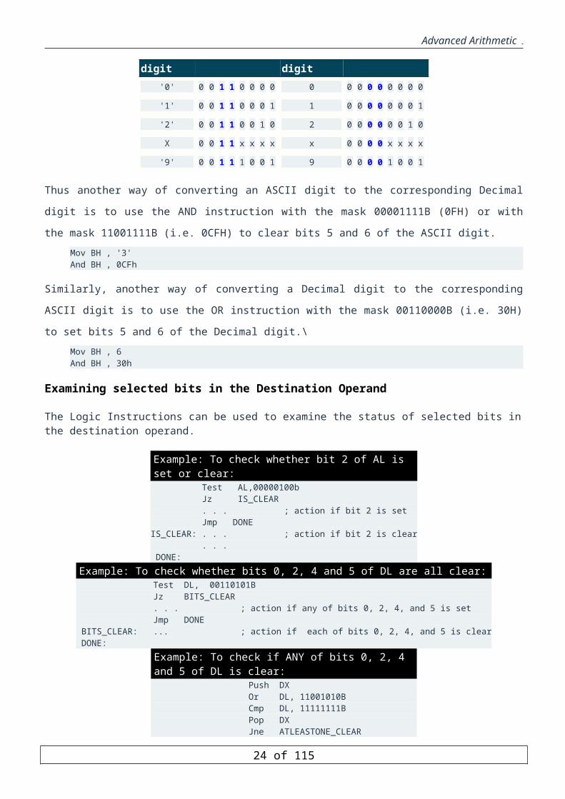
Converting an ASCII digit to a Decimal digit and vice versa:
For any ASCII digits, bit 4 and 5 of its ASCII code are 11 ; but for the corresponding decimal digit bit 4 and 5 are 00 . The remaining bits are similar:
ASCII digit ASCII code Decimal digit Binary code '0' 0 0 1 1 0 0 0 0 0 0 0 0 0 0 0 0 0
'1' 0 0 1 1 0 0 0 1 1 0 0 0 0 0 0 0 1
'2' 0 0 1 1 0 0 1 0 2 0 0 0 0 0 0 1 0
X 0 0 1 1 x x x x x 0 0 0 0 x x x x
'9' 0 0 1 1 1 0 0 1 9 0 0 0 0 1 0 0 1
Thus another way of converting an ASCII digit to the corresponding Decimal digit is to use the AND instruction
with the mask 00001111B (0FH) or with the mask 11001111B (i.e. 0CFH) to clear bits 5 and 6 of the ASCII digit.Mov BH , '3' And BH , 0CFh
Similarly, another way of converting a Decimal digit to the corresponding ASCII digit is to use the OR instruction
with the mask 00110000B (i.e. 30H) to set bits 5 and 6 of the Decimal digit.\Mov BH , 6 And BH , 30h
18 of 85

Advanced Arithmetic
Examining selected bits in the Destination Operand
The Logic Instructions can be used to examine the status of selected bits in the destination operand.
Example: To check whether bit 2 of AL is set or clear: Test AL,00000100b Jz IS_CLEAR . . . ; action if bit 2 is set Jmp DONEIS_CLEAR: . . . ; action if bit 2 is clear . . . DONE:
Example: To check whether bits 0, 2, 4 and 5 of DL are all clear: Test DL, 00110101B Jz BITS_CLEAR . . . ; action if any of bits 0, 2, 4, and 5 is set Jmp DONE BITS_CLEAR: ... ; action if each of bits 0, 2, 4, and 5 is clear DONE:
Example: To check if ANY of bits 0, 2, 4 and 5 of DL is clear: Push DX Or DL, 11001010B Cmp DL, 11111111B Pop DX Jne ATLEASTONE_CLEAR . . Jmp DONEATLEASTONE_CLEAR: . . .DONE:
Determine whether a general-purpose register is equal to zero
The followings are ways to examine whether or not any general-purpose register is equal to zero.Or AL, AL and EDX, EDX test ESI, ESI
Clearing a general-purpose register operand or a memory operand to zero
A register operand can be cleared to zero using any of the instructions: MOV, SUB, AND, and XOR. The
followings are ways to clear any general-purpose register to zero.mov BL, 0 sub AX, AX and CL, 0 xor DH, DH
A memory operand can be cleared to zero using either the MOV or AND instruction. The followings are ways to
clear any memory location to zero.mov VAR1, 0 and ARRAY[2], 0
Shift Instructions
There are three types of shift instructions
Logical shift instructions work on unsigned binary numbersSHLSHR
19 of 85

Advanced Arithmetic
Arithmetic shift instructions work on signed binary numbersSALSAR
Double Precision Shift instructions Works in wordsSHLDSHRD
There are two different formats for logical and arithmetic shift instructions:
SHL/SHR/SAL/SAR r/m, count SHL/SHR/SAL/SAR r/m, CL
count is an immediate value between 0 and 31. If a greater value is specified, Pentium takes only the least
significant 5 bits as the count value (MODULUS 32).Second format specifies count indirectly through CL
Only CL register can be used.
CL contents are not changed.
Useful if count value is known only at the run time as opposed at assembly time.
EFFECT of SHIFT INSTRUCTIONS on FLAGS
All shift instructions affect some flags like other instructions.
Auxiliary flag (AF): undefined.
Zero flag (ZF), Sign flag (SF) and parity flag (PF)are updated to reflect the result.
Carry flag (CF): Contains the last bit shifted out
Overflow flag (OF)
For multibit shifts : Undefined
For single bit shifts: OF is set if the leftmost bit has changed as a result of the shift, otherwise
cleared.
Logical Shift Instruction
Left shift (SHL)
SHL shifts the leftmost bit into the Carry Flag (CF) and overwrites the current value of the Carry Flag. Each of
the remaining bits is shifted leftwise and 0 is shifted into the rightmost bit.
Example: Shifting AL=3 leftwise by 1 bitmov AL, 3 Shl AL, 1 ; shift left AL 1 place
S O L U T I O NInitially AL = 3 = 0000 0011 Finally AL = 6 = 0000 0110CF = 0SF = 0ZF = 0 because the result is not equal to 0.PF = 1 because there are 2 bits 1 in AL.OF = 0 Why?
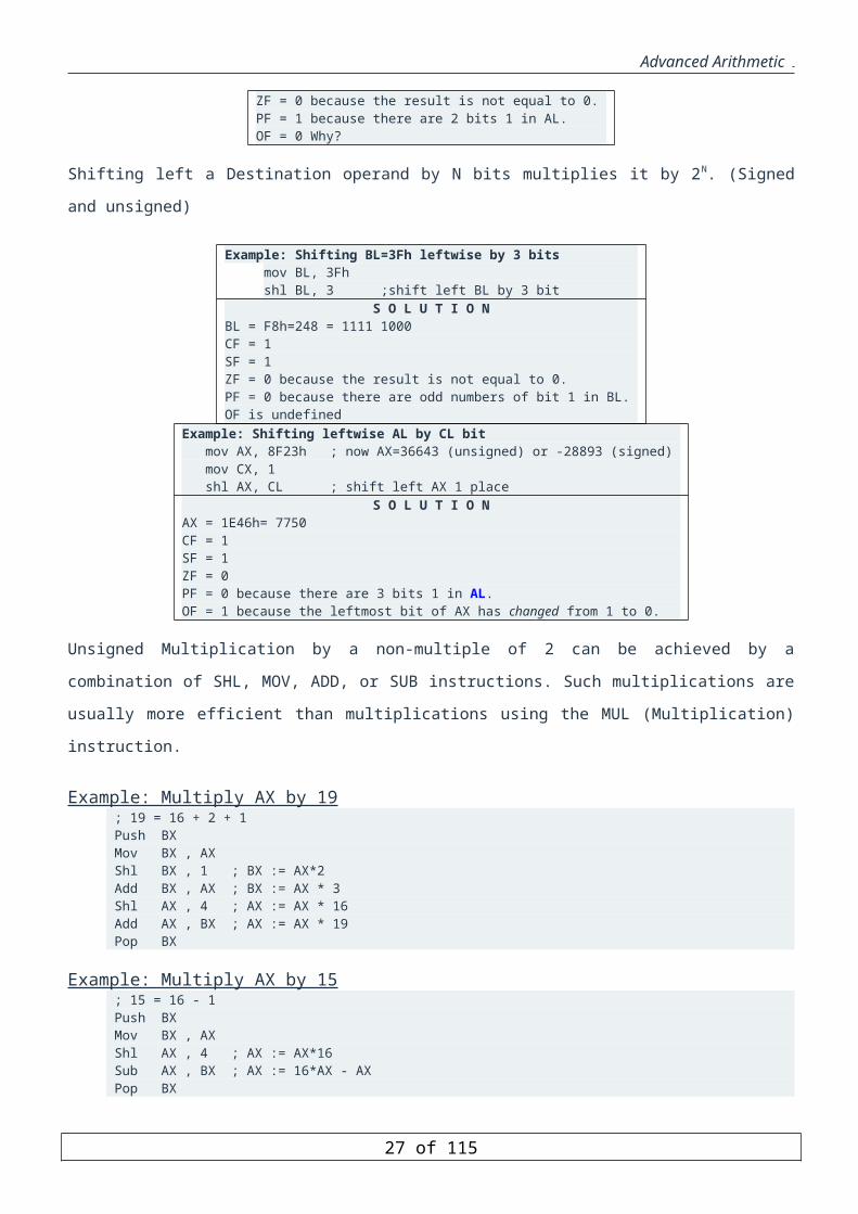
Shifting left a Destination operand by N bits multiplies it by 2N. (Signed and unsigned)
20 of 85
Advanced Arithmetic
Example: Shifting BL=3Fh leftwise by 3 bitsmov BL, 3Fhshl BL, 3 ;shift left BL by 3 bit
S O L U T I O NBL = F8h=248 = 1111 1000CF = 1SF = 1ZF = 0 because the result is not equal to 0.PF = 0 because there are odd numbers of bit 1 in BL.OF is undefined
Example: Shifting leftwise AL by CL bit mov AX, 8F23h ; now AX=36643 (unsigned) or -28893 (signed) mov CX, 1 shl AX, CL ; shift left AX 1 place
S O L U T I O NAX = 1E46h= 7750CF = 1SF = 1ZF = 0PF = 0 because there are 3 bits 1 in AL.OF = 1 because the leftmost bit of AX has changed from 1 to 0.
Unsigned Multiplication by a non-multiple of 2 can be achieved by a combination of SHL, MOV, ADD, or SUB
instructions. Such multiplications are usually more efficient than multiplications using the MUL (Multiplication)
instruction.
Example: Multiply AX by 19 ; 19 = 16 + 2 + 1 Push BX Mov BX , AX Shl BX , 1 ; BX := AX*2 Add BX , AX ; BX := AX * 3 Shl AX , 4 ; AX := AX * 16 Add AX , BX ; AX := AX * 19 Pop BX
Example: Multiply AX by 15 ; 15 = 16 - 1 Push BX Mov BX , AX Shl AX , 4 ; AX := AX*16 Sub AX , BX ; AX := 16*AX - AX Pop BX
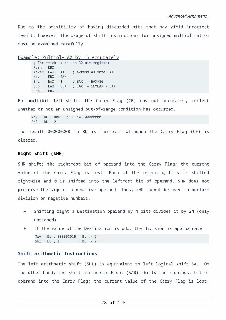
Due to the possibility of having discarded bits that may yield incorrect result, however, the usage of shift
instructions for unsigned multiplication must be examined carefully.
Example: Multiply AX by 15 Accurately ; The trick is to use 32-bit register Push EBX Movzx EAX , AX ; extend AX into EAX Mov EBX , EAX Shl EAX , 4 ; EAX := EAX*16 Sub EAX , EBX ; EAX := 16*EAX - EAX Pop EBX
For multibit left-shifts the Carry Flag (CF) may not accurately reflect whether or not an unsigned out-of-range
condition has occurred.Mov BL , 80H ; BL := 10000000bShl BL , 2
21 of 85
Advanced Arithmetic
The result 00000000B in BL is incorrect although the Carry Flag (CF) is cleared.
Right Shift (SHR)
SHR shifts the rightmost bit of operand into the Carry Flag; the current value of the Carry Flag is lost. Each of the
remaining bits is shifted rightwise and 0 is shifted into the leftmost bit of operand. SHR does not preserve the sign
of a negative operand. Thus, SHR cannot be used to perform division on negative numbers.
Shifting right a Destination operand by N bits divides it by 2N (only unsigned).
If the value of the Destination is odd, the division is approximateMov BL , 00000101B ; BL := 5 Shr BL , 1 ; BL := 2
Shift arithmetic Instructions
The left arithmetic shift (SHL) is equivalent to left logical shift SAL. On the other hand, the Shift arithmetic Right
(SAR) shifts the rightmost bit of operand into the Carry Flag; the current value of the Carry Flag is lost. Each of
the remaining bits is shifted rightwise and, in addition, the leftmost bit is shifted into itself.
Double Precision Shift Instructions
The format of Double Shift instructions
SHLD/SHRD r/m16, r16, imm8 SHLD/SHRD r/m32, r32, imm8 SHLD/SHRD r/m16, r16, CL SHLD/SHRD r/m32, r32, CL
All double precision shift instructions DO NOT MODIFY the second operand. The second operand only feeds
their bits to the first operand.
Rotate Instructions
Rotate instructions are unparalleled instructions compared to any high level languages. A rotate operation shifts
the bits within a cell without discarding. For example, a rotate right shifts bits to the right. Instead of throwing
away the rightmost bit (LSB), it is placed in the leftmost position of the rotated cell.
There are two types of rotate instructions:
Rotate Without Carry instructions
ROL (ROtate Left)
ROR (ROtate Right)
Rotate through carry instructions
RCL (Rotate through Carry Left)
RCR (Rotate through Carry Right)
22 of 85
Advanced Arithmetic
General syntax format
There are two different formats:ROL/ROR/RCL/RCR r/m, count ROL/ROR/RCL/RCR r/m, CL
First format directly specifies the count value
Count is an immediate expression between 0 and 31.
If a greater value is specified, Pentium takes only the least significant 5 bits as the count value
(MODULUS 32).
Second format specifies count indirectly through CL
Only CL register can be used.
CL contents are not changed.
Useful if count value is known only at the run time as opposed at assembly time.
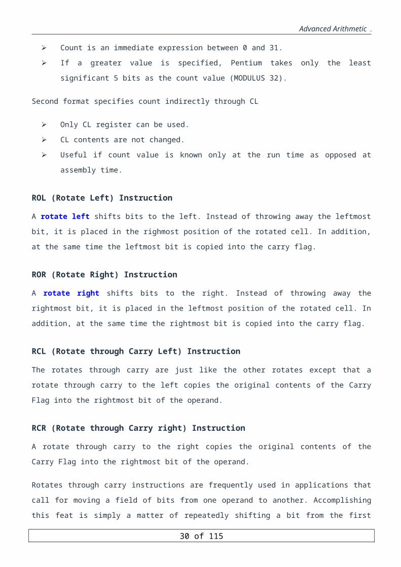
ROL (Rotate Left) Instruction
A rotate left shifts bits to the left. Instead of throwing away the leftmost bit, it is placed in the righmost position
of the rotated cell. In addition, at the same time the leftmost bit is copied into the carry flag.
ROR (Rotate Right) Instruction
A rotate right shifts bits to the right. Instead of throwing away the rightmost bit, it is placed in the leftmost
position of the rotated cell. In addition, at the same time the rightmost bit is copied into the carry flag.
RCL (Rotate through Carry Left) Instruction
The rotates through carry are just like the other rotates except that a rotate through carry to the left copies the
original contents of the Carry Flag into the rightmost bit of the operand.
RCR (Rotate through Carry right) Instruction
A rotate through carry to the right copies the original contents of the Carry Flag into the rightmost bit of the
operand.
Rotates through carry instructions are frequently used in applications that call for moving a field of bits from one
operand to another. Accomplishing this feat is simply a matter of repeatedly shifting a bit from the first operand
into the Carry flag and rotating that bit out of the carry Flag and into the second operand.
Example: Shifting 64-bit number in EDX:EAX mov CX, N ;N bit shift@1: shl EAX, 1 ;moves leftmost bit of EAX to CF rcl EDX, 1 ;CF goes to rightmost bit of EDX
23 of 85
Advanced Arithmetic
loop @1
; The above can be done using SHLD instruction shld EDX, EAX, N shl EAX, N
Example: Code fragment to reverse the contents of AL
The main idea is to shift left the bits of AL, once at a time, and put them in BL such that we end up with:
AL = 0 0 0 0 0 0 0 0BL = a0 a1 a2 a3 a4 a5 a6 a7
We then copy BL to AL
Push BX push CX mov CX, 8@1: shl AL, 1 Rcr BL, 1 loop @1 pop CX pop BX
Exercise: 1
Initially, the contents of AL is as folows: a7 a6 a5 a4 a3 a2 a1 a0
Write a code fragment to set the contents of AL as a0 a1 a2 a3 a7 a6 a5 a4
Exercise 2
Suppose the initial content of AX is
0 0 0 0 0 0 0 0 a7 a6 a5 a4 a3 a2 a1 a0
Write a code fragment to insert 3 bit 0s into AX such that the content of AX is
0 0 0 0 0 a7 a6 0 0 0 a5 a4 a3 a2 a1 a0
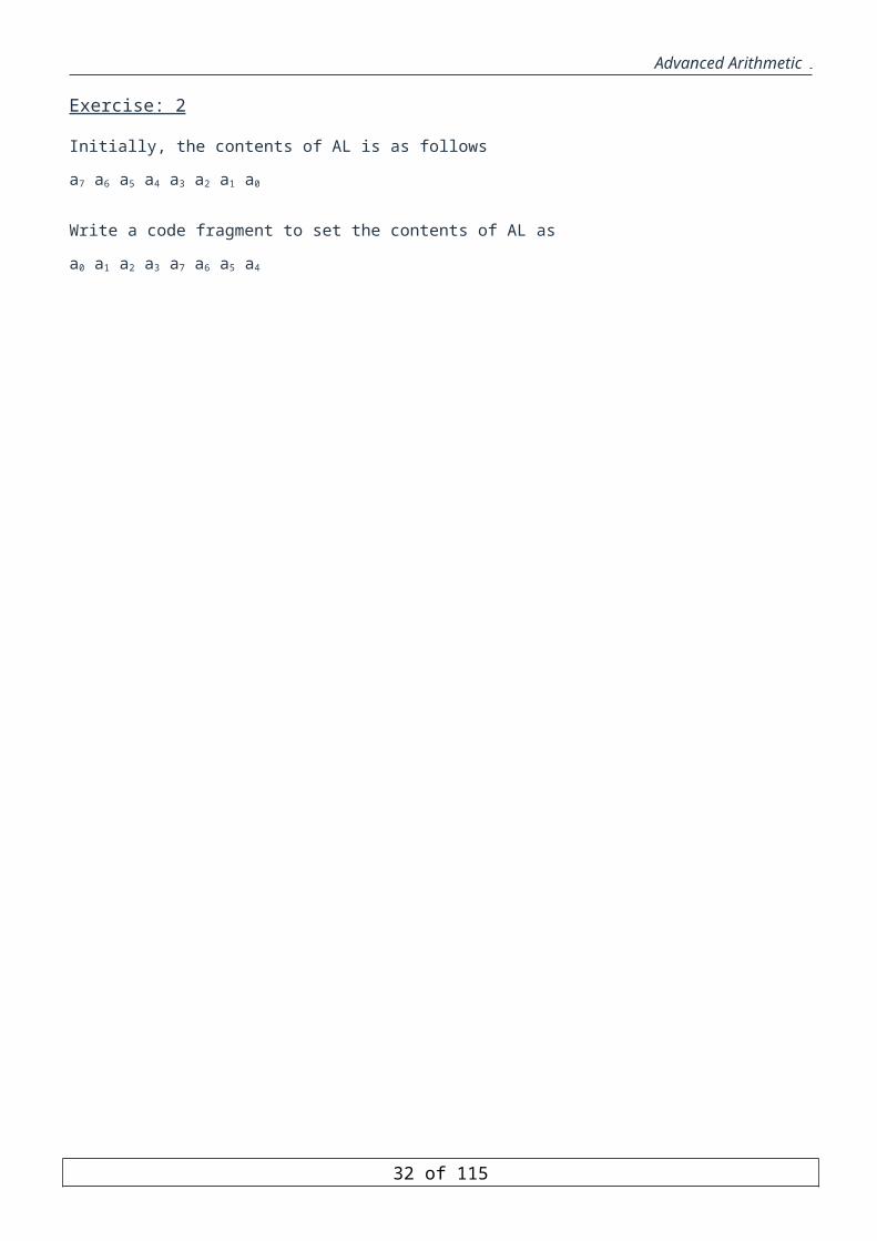
Exercise: 2
Initially, the contents of AL is as follows
a7 a6 a5 a4 a3 a2 a1 a0
Write a code fragment to set the contents of AL as
a0 a1 a2 a3 a7 a6 a5 a4
24 of 85

Advanced Arithmetic
Flow Control Instructions
The objectives of this unit are to cover the following topics:
CMP instruction
Unconditional jump instruction
Short, near and far jumps.
Direct and indirect jumps.
Conditional jump instructions
Single Flag based jump instructions
Signed conditional jump
Unsigned conditional jump
Loop instructions
Loop
LoopE and LoopZ
LoopNE and LoopNZ
Introduction
Flow control instructions are used to control the flow of a program.
Flow control instructions can be of two types: unconditional and conditional.
The JMP instruction is the only unconditional flow control instruction.
The conditional flow control instructions come in three types:
Jump instructions that test a single flag
Jump instructions after Unsigned Comparisons
Jump instructions after Signed Comparisons
Such Jump instructions are usually used after a compare (CMP) instruction, arithmetic, logic, or shift operations.
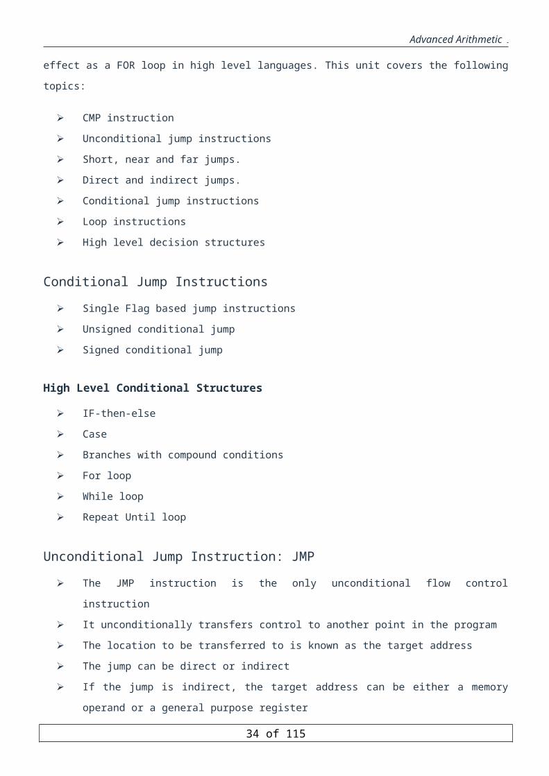
Another type of flow control instruction is the LOOP instruction that is usually used to get the same effect as a
FOR loop in high level languages. This unit covers the following topics:
CMP instruction
Unconditional jump instructions
Short, near and far jumps.
Direct and indirect jumps.
Conditional jump instructions
Loop instructions
High level decision structures
25 of 85

Advanced Arithmetic
Conditional Jump Instructions
Single Flag based jump instructions
Unsigned conditional jump
Signed conditional jump
High Level Conditional Structures
IF-then-else
Case
Branches with compound conditions
For loop
While loop
Repeat Until loop
Unconditional Jump Instruction: JMP
The JMP instruction is the only unconditional flow control instruction
It unconditionally transfers control to another point in the program
The location to be transferred to is known as the target address
The jump can be direct or indirect
If the jump is indirect, the target address can be either a memory operand or a general purpose register
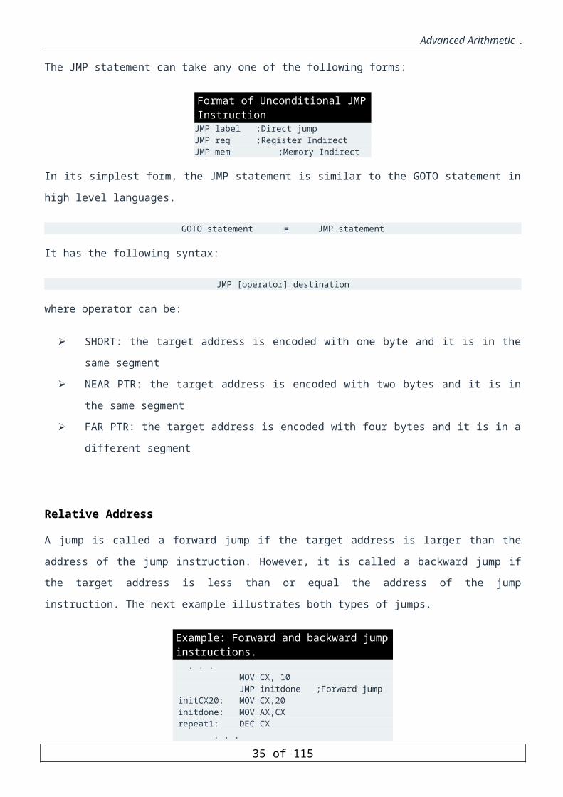
The JMP statement can take any one of the following forms:
Format of Unconditional JMP InstructionJMP label ;Direct jumpJMP reg ;Register IndirectJMP mem ;Memory Indirect
In its simplest form, the JMP statement is similar to the GOTO statement in high level languages.
GOTO statement = JMP statement
It has the following syntax:
JMP [operator] destination
where operator can be:
SHORT: the target address is encoded with one byte and it is in the same segment
NEAR PTR: the target address is encoded with two bytes and it is in the same segment
FAR PTR: the target address is encoded with four bytes and it is in a different segment
26 of 85
Advanced Arithmetic
Relative Address
A jump is called a forward jump if the target address is larger than the address of the jump instruction. However,
it is called a backward jump if the target address is less than or equal the address of the jump instruction. The next
example illustrates both types of jumps.
Example: Forward and backward jump instructions. . . . MOV CX, 10 JMP initdone ;Forward jump initCX20: MOV CX,20 initdone: MOV AX,CX repeat1: DEC CX . . . JMP repeat1 ;Backward jump . . .
In 16-bit addressing, 16-bits are required to store the offset address i.e. 2 bytes. However, analyzing most of the
jumps occurring in a program, it can be observed that they are within a close distance to the jump instruction.
Thus, to reduce the code size of the jump instruction we can encode the target address with one byte instead of
two bytes. This can be achieved by storing the difference target - IP in the instruction instead of storing the actual
target address. The difference can fit in a byte if it is within the range -128 to +127. When the CPU executes the
jump instruction, it will get the difference target-IP from the instruction and will add to it IP, i.e., target-
IP+IP=target, and will obtain the required target address. Jump instructions with the difference target-IP fitting in
one byte are called short jumps.
A jump is called a near jump if the target address is in the same code segment at any location ranging from -
32,768 to +32,767 bytes from the IP. When the jump address is within the same segment, the jump is called intra-
â€ژsegment jump. If the jump address is outside the current segment, the jump is referred to â€ژas inter-segment
jump.
The jump is a far jump if the target address is in a different code segment. In this case, the assembler stores the
code segment and the offset of the target address within that segment in the instruction.
The table below summarizes all the addressing modes used with the unconditional jump instruction.
Label Pointer Range Addressing Mode Size Encoded as Directive Short +127 -127Byte Immediate Word Relative SHORT Near Intra-segment Immediate Word Relative Near Ptr Near Intra-segment Register Word Absolute address Near Ptr Near Intra-segment Memory Word Absolute address Near Ptr Far Inter-segment Immediate Double Word Absolute address Far Ptr Far Inter-segment Memory Double Word Absolute address Far Ptr
The assembler can automatically select the SHORT jump and allocate one byte, if appropriate. So, we do not need
to explicitly specify SHORT or NEAR PTR for addresses in the same segment as the assembler will select the
appropriate type. The next example demonstrates the encodings of short, near, and far jumps.
27 of 85
Advanced Arithmetic
Example: Encodings of short, near, and far jumps. 0005 33 C0 XOR AX, AX 0007 40 Back: INC AX 0008 EB 10 JMP Forward 000A B9 000A MOV CX, 10 000D E9 000A JMP Near PTR Forward 0010 B9 0014 MOV cx, 20 0013 EA ---- 001A R JMP Far PTR Forward 0018 8B C1 MOV AX, CX 001A 03 C0 Forward: ADD AX, AX 001C EB E9 JMP Back
As can be seen from the example, for both forward and backward jumps that can be encoded as short will be
allocated one byte by the assembler. For example, the address of the label Forward is 001A. The IP address after
the instruction JMP Forward has the value 000A. Thus, the difference 001A-000A=0010. Since the difference can
fit in a byte, 10 is what is stored in the instruction.
However, for the instruction JMP Near PTR Forward, the IP has a value 0010. So, the difference is 001A-
0010=000A. Although the difference can fit in one byte, two bytes are allocated since we explicitly specified that
the target is Near.
For the instruction JMP FAR PTR Forward, four bytes are allocated, two for the segment and two for the offset.
Here, the absolute address is stored not the relative address. So, the offset 001A is stored. The two bytes for the
segment will be assigned once the program is loaded and the segment is determined.
For the instruction, JMP Back, the address of the label Back is 0007 and the value of IP is 001E. So, the
difference is 0007-001E=0007+FFE2=FFE9. Since the difference can fit in a byte, one byte is allocated and the
value E9 is stored.
CMP Instruction
The compare instruction (CMP) can be used to compare two numbers or test conditions
When comparing numbers, at most one of these numbers can reside in memory
The CMP instruction updates the arithmetic flags by performing: destination - source
Unlike the SUB instruction the destination operand is not affected
The values of the status flags are set according to the result of the subtraction
The flags can be tested by a subsequent conditional jump instruction
The CMP instruction has the following format:
CMP destination, source
Observing the following rules:
The destination can be a register or memory operand
The source can be a register, memory operand, or an immediate operand
At most one of the operands may reside in memory.
28 of 85

Advanced Arithmetic
A conditional jump instruction is usually used after a CMP instruction This gives the ability to split the program
flow into one of two paths depending upon some logical condition. As an example, the following code increments
the AX register if BX is equal to CX.
CMP instruction CMP BX, CX ;Compare BX to CX JNE SkipStmt ;If BX ≠CX skip INC AX ;AX = AX + 1SkipStmt :
Conditional Jump Instructions
Conditional jump instructions are the basic tools for creating selective structures like the IF..ENDIF
statement and repetitive structures like loops.
A conditional jump tests one or more flags in the flags register
If the flag settings match the instruction, control transfers to the target location
If the match fails, the CPU ignores the conditional jump and execution continues with the next
instruction.
Most of the time, a conditional jump is executed after a CMP instruction.
The CMP instruction sets the flags so that test can be carried out for less than, greater than, equality, etc.
Conditional jump instructions take the following form:
Jcc label;
The “cc” in Jcc indicates that some character sequence, specifying the type of condition to be tested, must be
substituted. For example, JS stands for jump if the sign flag is set and JC stands for jump if the carry flag is set.
Conditional jumps test the sign (S), zero (Z), carry (C), parity (P), and overflow (O) flags.
When comparing two numbers it is necessary to know whether these numbers are representing signed or unsigned
numbers in order to establish a relationship between them. For example, suppose that AL=FF and BL=01. If we
execute the instruction CMP AL, BL, the result of the comparison will be different depending on whether the
registers represent signed or unsigned numbers. If unsigned numbers are represented, then AL=255 and BL=1 and
hence AL is greater than BL. However, if signed numbers are represented, then AL=-1 and BL=1 and hence BL is
greater than AL. Thus, we need conditional jump instructions for unsigned number comparison and conditional
jump instructions for signed number comparison.
Conditional jump instructions are divided into three main types:
Single Flag Based Jump Instructions
Unsigned Conditional Jump Instructions
29 of 85
Advanced Arithmetic
Signed Conditional Jump Instructions
Addressing Modes
Unlike the unconditional JMP instruction, the conditional jump does not provide an indirect form.
The only form they allow is a branch to a statement label in your program.
Conditional jump instructions are only of type SHORT.
Since unconditional jump instructions can be only of type SHORT, if the target address is not within a range of -
128 to +127 from the IP, then a remedy is needed. The following example shows two implementations of a
program one when the target address is within a SHORT range and the other when it is in a Near range.
Example: Target address is SHORT. CMP AX, BX ; compare ax to bx to set flags JE THERE ; if equal, then skip next statement ADD AX, 0002H ; correction statementTHERE: MOV CL, 07H ; load count
Example: Target address is Near. CMP AX, BX ; compare AX to BX to set flags JNE FIX ; if not equal, then goto label FIX JMP THERE ; otherwise, unconditional jump to thereFIX: ADD AX, 0002H ; correction statementTHERE: MOV CL, 07H ; load count
Single-Flag Based Jump Instructions
The Pentium instruction set provides two types of jump instructions that are based on testing a single flag. One
type is for jumps taken if the flag is set and the other for jumps taken if the flag is clear. There are two instructions
for each of the flags: CF, OF, SF, ZF, PF. The only flag, from the arithmetic flags, that does not have such
instructions is the Auxiliary Flag. These instructions are summarized in the table below.
Instruction Description Condition Aliases JC Jump if carry CF = 1 JB, JNAE JNC Jump if no carry CF = 0 JNB, JAE JZ Jump if zero ZF = 1 JE JNZ Jump if not zero ZF = 0 JNE JS Jump if sign SF = 1 JNS Jump if no sign SF = 0 JO Jump if overflow OF = 1 JNO Jump if no overflow OF = 0 JP Jump if parity PF = 1 JPE JPE Jump if parity even PF = 1 JP JNP Jump if no parity PF = 0 JPO JPO Jump if parity odd PF = 0 JNP
There are many applications for these instructions. For example, to check if the result is positive or negative, one
can use the JNS and JS instructions. To check if the result of an operation on a signed number is correct or not,
one can use the instructions JO and JNO. To check if the result is zero or not, one can use the instructions JZ and
JNZ. To check if the result of comparing two values is equal or not, one can also use the JZ/JE and JNZ/JNE
30 of 85

Advanced Arithmetic
instructions. To check if the result of an operation on an unsigned number is correct or not, once can use the
instructions JC and JNC. Furthermore, to check if the last bit shifted or rotated is 1 or 0, one can use the
instructions JC and JNC.
The next example demonstrates the use of the JC instruction in counting the number of 0's in register AL and
storing the count in register AH.
Example: Use of the JC instruction. XOR AH, AH MOV CX, 8Next: ROL AL, 1 JC Skip INC AHSkip: LOOP Next
In the next example, we demonstrate the use of the JNC instruction in displaying the binary content of register
BX.
Example: Use of the JNC instruction. MOV AH, 2ژ MOV CX, 16Next MOV DL, 30H ROL BX, 1 JNC Skip ADD DL, 1Skip: INT 21H LOOP Next
The following example illustrates the use of the JNZ instruction. Notice that the loop is iterated until the content
of BX becomes equal to zero and the zero flag (ZF) is set to one.
Unsigned Conditional Jump Instructions
Conditional jump instructions for unsigned comparisons deal with numbers that are positive numbers only. The
following table shows the condition flags used in unsigned comparison and their meanings.
Flags Meaning ZF = 1 equality ZF = 0 inequality CF = 1 A < B CF = 0 A > B
Note that if number A is less than number B, there will be a borrow when B is subtracted from A. This will set the
CF to 1 to indicate that there was a borrow. However, if A is greater than B, there will be no borrow and hence
CF=0. The following table shows all possible conditional jump instructions for unsigned number comparisons.
The table also shows the flags condition for a jump to be taken.
Instruction Equivalent Meaning (jump if) Condition JA JNBE Above (not below or equal) CF = 0 and ZF = 0
31 of 85
Advanced Arithmetic
JAE JNB Above or equal (not below) CF = 0 JB JNAE Below (not above or equal) CF = 1 JBE JNA Below or equal (not above) CF = 1 or ZF = 1 JE JZ Equal (zero) ZF = 1 JNE JNZ Not equal (not zero) ZF = 0
Signed Conditional Jump Instructions
Signed conditional jump instructions are used to test signed numbers. Signed numbers use 2's complement
representation. Note that equal and not equal comparisons are the same for signed and unsigned numbers and are
based on the Zero flag (ZF). The following table shows all possible conditional jump instructions for signed
number comparisons. The table also shows when a jump is taken based on the status flags.
Instruction Equivalent Description (Jump If) Condition JG JNLE greater (not less or equal) SF = OF and ZF=0 JGE JNL greater or equal (not less) SF = OF JL JNGE less (not greater or equal) SF <> OF JLE JNG less than or equal (not greater) SF <> OF or ZF = 1 JE JZ equal ZF = 1 JNE JNZ not equal ZF = 0
The next table shows a set of two numbers n1, n2 and the result of executing the instruction CMP n1, n2 on the
flags ZF, OF, SF.
n1 n2 ZF OF SF 56 55 0 0 0 56 -55 0 0 0 -55 -56 0 0 0 55 -75 0 1 1 55 55 1 0 0 55 56 0 0 1 -55 56 0 0 1 -56 -55 0 0 1 -57 55 0 1 0
It can observed from the above table that when n1 is greater than n2, the OF is equal to the SF. Also, it can be
observed that when n1 is smaller than n2 the OF is not equal to the SF. However, it can be observed that when the
two numbers are equal, the OF is also equal to the SF. Thus, the condition for checking whether n1 is greater than
n2 is that the OF is equal to the SF and that the ZF=0. On the other hand, it is sufficient to check that the OF is not
equal to the SF to know that n1 is smaller than n2.
Loop InstructionsThe LOOP instruction is mainly used to simulate the different loops in HLL. The Loop instructions use the CX
register to indicate the loop count. The syntax of the Loop instruction is:
32 of 85

Advanced Arithmetic
LOOP label
The Loop instruction decrements CX without changing any flags
If CX is not zero after the decrement, control is transferred to the destination label
The jump is a SHORT jump only
Note that the ECX register can be used as a loop counter in 32-bit mode. However, in this case, one has to use the
instruction LOOPD instead of LOOP.
The following example illustrates the use of the Loop instruction in implementing a corresponding for loop in
HLL.
Example: For Loop in HLL. … for (x=9;x>0;x--) n += x; …
Example: Implementing For Loop in Assembly. … ;for(x=9;x>0;x--) MOV CX,9toploop: ADD n,CX ;n=n+x … LOOP toploop
LOOPZ/LOOPE and LOOPNZ/LOOPNE Instructions
In these two additional instructions, the state of the ZERO Flag may also cause loop termination in addition to the
content of the CX register. Some action inside the loop should affect the zero flag (e.g. a CMP instruction) before
these instructions are executed.
LOOPZ/LOOPE: Loop while (ZF = 1) && (CX<> 0)
LOOPNZ/LOOPNE: Loop while (ZF = 0) && (CX <> 0)
LOOPZ is equivalent to LOOPE
LOOPNZ is equivalent to LOOPNE
The format of the loop instructions along with the action taken is given in the following table:
Instruction Action LOOP target CX= CX-1 ; if (CX <> 0) jump to target LOOPE/LOOPZ target CX= CX-1 ;if (CX <> 0) AND (ZF=1) jump to target LOOPNE/LOOPNZ target CX= CX-1 ;if (CX <> 0) AND (ZF=0) jump to target
The following example illustrates the use of the LOOPNE instruction. It accepts at most 9 characters from the
keyboard, and when the 9th character is pressed (or the enter key is used) the number of key presses is displayed.
Example: Use of the LOOPNE instruction. …
33 of 85
Advanced Arithmetic
MOV AH,1 MOV CX,9NextChar: INT 21H CMP AL,13â€ژ LOOPNE NextChar ;Determine Count MOV AX, 0239H SUB AL,CL MOV DL,AL INT 21H …
The JCXZ instruction
It should be observed that the Loop instructions execute one iteration before decrementing CX and checking if its
value is 0. So, if the initial value of CX is 0, then CX will become FFFF and the loop will repeat for 2^16=65536
times. The instruction JCXZ provides a solution for this problem by testing the CX register and if zero, control is
transferred to the target instruction. The format of this instruction is JCXZ target
Note that this instruction is equivalent to CMP CX, 0JZ target
except that JCXZ does not affect the flags, while the CMP/JZ combination affect the flags. The following
example demonstrates a program that asks the user to enter a character (a-z), and counts all upper case and lower
case characters in a Table defined in the data segment. Assume that the table size is 100 bytes.
Example: Use of the LOOPNE and JCXZ instructions. … MOV AH, 1 ; read a character INT 21H AND AL, 20H ; convert character to upper case XOR SI, SI ; character count XOR BX, BX ; table index MOV CX, 100â€ژNext: JCXZ Done MOV DL, Table[BX] ; get character from table INC BX AND DL, 20H ; convert character to upper case CMP AL, DL LOOPNE Next JNE Done INC SI JMP NextDone: …
The next example demonstrates a program that counts the number of non-blank characters in a Table defined in
the data segment. Assume that the table size is 100 bytes.
Example: Use of the LOOPE and JCXZ instructions. … XOR SI, SI ; character count MOV BX, -1 ; table index
34 of 85
Advanced Arithmetic
MOV CX, 100â€ژNext: JCXZ Done INC BX CMP Table[BX], ' ' LOOPE Next JE Done INC SI JMP NextDone: …
Implementing High-Level Language Decision Structures
Modern High-level languages provide a variety of decision structures. These structures include selection
structures such as if constructs and iterative structures such as while and for loop constructs. Assembly language
does not provide these structures directly. However, it provides several basic instructions that can be used to
construct these high-level selection and iterative structures. In this section, we demonstrate how these structures
can be implemented in assembly language.
IF-Then and IF-THEN-ELSE Structures
The following is a pseudo code that shows the if-then structure used in a high level language.
Example: IF-THEN Structure in HLL. int n; if (n>7) do_it(); ...
Here is an implementation of the if-then structure in assembly language.
Example: Implementing IF-THEN Structure in Assembly....;if (n>7)CMP n, 7JNA skip;then-partCALL do_it;end ifskip:...
The following is an example of an if-then-else structure implementation in assembly language.
Example: IF-THEN-ELSE Structure in HLL. char n; ... if (n=='7') do_it(); else do_that();Example: Implementing IF-THEN-ELSE Structure in Assembly. ;if (n == '7') CMP n,'7' JNE else_ ;then-part CALL do_it JMP SHORT endifelse_: CALL do_that
35 of 85

Advanced Arithmetic
endif: ...
IF Structure with Logical Operators
The next example demonstrates the implementation of the IF structure with an AND logical operator. It tests
whether ch is a lower case character or not. If it is a lower case it converts it to upper case.
Example: IF Structure with an AND logical operator in HLL. if ((ch >= 'a') && (ch <= 'z')) ch = ch - 32 ;
Example: Implementing IF Structure with an AND logical operator in Assembly. CMP ch, 'a' JB NotLowerCase CMP ch, 'z' JA NotLowerCaseLowerCase: SUB ch, 32NotLoweCase: ...
In the next example, we demonstrate the IF structure with an OR logical operator. The function display() is called
if the entered character is either an upper case 'Y' or lower case 'y' character.
Example: IF Structure with an OR logical operator in HLL. if ((ch = 'y') || (ch = 'Y')) display();
Example: Implementing IF Structure with an OR logical operator in Assembly. CMP ch, 'y' JE Skip CMP ch, 'Y' JNE DoneSkip: call displayDone: ...
CASE Statement
A CASE statement is a multi-way branch structure that tests a register, variable, or expression for particular
values or a range of values. The general form is a s follows:
CASE expressionvalues-1: statements-1values-2: statements-2...values-n: statements-n
EndCase
In this structure, the expression is tested and if its value is a member of the test values-i, then statements-i are
executed. It is assumed that values-1,..., values-n are disjoint.
The following example illustrates the case statement in HLL and its implementation in assembly.
Example: Case Statement in HLL.CASE AX
36 of 85

Advanced Arithmetic
<0: BX=-1=0: BX=0>0: BX=1
EndCaseExample: Implementing Case Statement in assembly.; case AX
CMP AX, 0 ; test AX JL Negative ; AX < 0 JE Zero ; AX=0 MOV BX, 1 ; AX>0 JMP EndCase
Negative: MOV BX,-1 JMP EndCase
Zero: MOV BX, 0EndCase:
Note that in the above example one CMP instruction is needed, because jump instructions do not affect the flags.
We next give another example illustrating the CASE statement.
Example: Another Case Statement in HLL.CASE A
1, 3: display 'o'2, 4: display 'e'
EndCaseExample: Implementing another Case Statement in assembly.; case AL; 1, 3
CMP AL, 1 JE Odd CMP AL, 3 JE Odd
; 2, 4 CMP AL, 2 JE Even CMP AL, 4 JE Even
; not 1..4 JMP EndCase
Odd: MOV DL, 'o' JMP Display
Even: MOV DL, 'e'Display: MOV AH, 2
INT 21HEndCase:
WHILE Structure
The WHILE loop tests a condition before executing the loop body. The loop body is executed repeatedly as long
as the condition is true.
Example: WHILE Structure in HLL. int n; ... while (n>0) n = n-2; ...
Example: Implementing WHILE Structure in Assembly....;while (n>0)while: CMP n,0
37 of 85
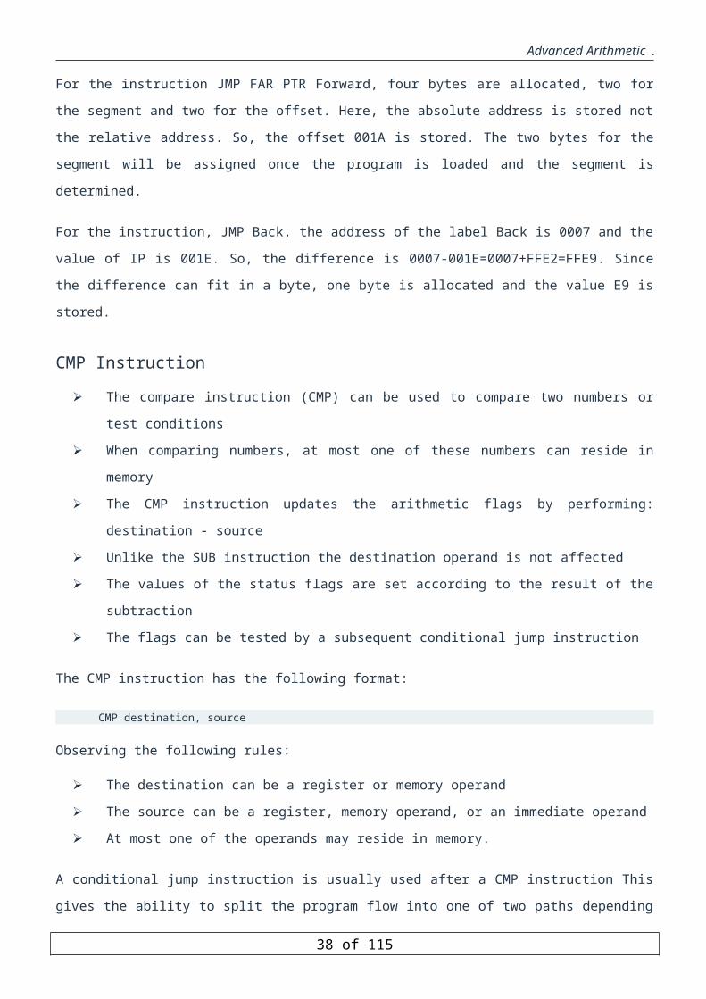
Advanced Arithmetic
JLE endwhile ;loop-body SUB n,2 JMP whileendwhile:...
Repeat-Until Structure
The Repeat-Until or Do-While structures test the repeat condition after executing the loop body. Thus, the loop
body is executed at least once. The next example is a program that reads a string of characters and stores it in a
table until a carriage return character is encountered, implementing a Repeat-Until Structure.
Example: Implementing Repeat-Until Structure in Assembly. XOR SI, SI ; initialize table index MOV AH, 1 ; reading a character Repeat: INT 21H MOV TABLE[SI], AL
INC SI CMP AL, 13 ; until condition
JNE Repeat ...
Indirect Jump Example
In direct jump, the target address (i.e. its relative offset value) is encoded into the jump instruction itself.
However, in an indirect jump, the target address is specified indirectly either through memory or a general-
purpose register.
For example, if the CX register contains the offset of the target address, then we can write
JMP CX
It should be observed that in indirect jumps, the target offset is the absolute value (unlike direct jumps, which use
a relative offset value). The following example illustrates the use of indirect jump.
Example: An example with an indirect jump. .MODEL SMALL .STACK 100H .DATA jump_table DW code_0 ; indirect jump pointer table DW code_1 DW code_2 DW default_code ; default code for digits 3-9 DW default_code DW default_code DW default_code DW default_code DW default_code DW default_code prompt_msg DB 10,13,'Enter a digit (0-9):$' msg_0 DB 10,13,'Economy class selected.$' msg_1 DB 10,13,'Business class selected.$' msg_2 DB 10,13,'First class selected.$' msg_default DB 10,13,'Not a valid code!$' .code
38 of 85

Advanced Arithmetic
MOV AX, @DATA MOV DS, AX read_again: MOV AH, 9 ; request a digit LEA DX, prompt_msg INT 21H MOV AH, 1 ; read input digit INT 21H SUB AL, '0' ; convert to numeric equivalent XOR AH, AH ; AH=0 MOV SI, AX ; SI is index into jump_table ADD SI, SI ; SI = SI *2 JMP jump_table[SI] ; indirect jump based on SI test_termination: CMP AL, 2 JA done jmp read_again code_0: MOV AH, 9 LEA DX, msg_0 INT 21H JMP test_termination code_1: MOV AH, 9 LEA DX, msg_1 INT 21H JMP test_termination code_2: MOV AH, 9 LEA DX, msg_2 INT 21H JMP test_termination default_code: MOV AH, 9 LEA DX, msg_default INT 21H JMP test_termination done: MOV AH, 4CH ; exit to DOS INT 21H END
The above example shows a simple program that reads a digit from the user and prints the corresponding choice
represented by the input. In order to use the indirect jump, a jump table of pointers is built. The input digit is
converted to act as an index into this table and is used in the indirect jump instruction.
39 of 85
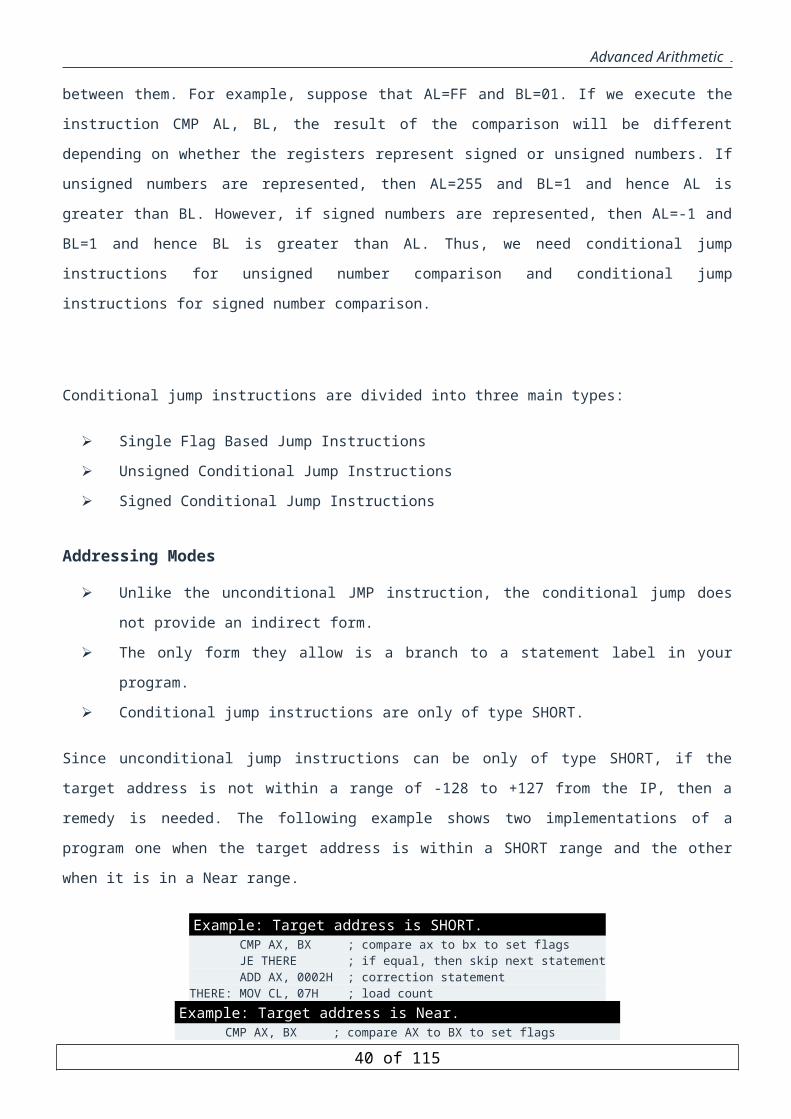
Advanced Arithmetic
Stack and Procedures
Objectives
To understand the implementation of the stack in Pentium architecture.
To learn to organize a program into procedures.
To learn how to use the following Pentium instruction in a program: PUSH, POP, PUSHF, POPF,
PUSHA, POPA, PUSHAD, POPAD, CALL, RET.
To learn how to use Pentium stack for passing parameters.
To learn how to assemble and link seperate files together using EXTRN and PUBLIC.
To learn how to create a library of procedures and link to it.
To learn how to use Pentium stack for declaring local variables.
The Stack
Stack is a very basic ADT (Abstract Data Type) that has many implementations in computer-related fields. The
characteristics of a stack can be summarized as follows:
Stack is a LIFO (Last-in First-out) process.
Stack must have a pointer called Top of Stack (TOS) that always refers to the top of stack.
Stack then must have two mandatory methods. The first is called Push(). The second is called Pop(). The
push method is needed to put a new item into the stack and the pop method is intended for removing an
item from the top of stack.
Stack must also have a base. From which the stack grows up and shrinks down.
Pentium processors have a built-in stack. This stack is implemented as an array of consecutive memory cells.
Because of array characteristic, the stack in Pentium has limited size.
SS:[SP] always points to the top of stack.
SS:[0] is the end of the stack. At this point, the stack is full.
Initially, SS:[SP] is set to the particular address that depends upon the stack size. This address may be
viewed as the base. At this point, the stack is empty. The size of the stack is defined by the programmer
using directive .STACK. .STACK 200h means the maximum size of the stack is fixed to 512 bytes.
Every time a new item is about to be put to the stack, the content of SP register is decremented first and
then the new item is placed in that location. This mechanism ensures that SS:[SP] always points to the
top of stack.
Every time the last item put in the stack is going to be removed, Pentium reads the item from the
location referred by SS:[SP] and stores it in another location. After that, Pentium adjusts the TOS by
incrementing SS:[SP].
However, Pentium can push/pop only either word (16-bit) or doubleword (32-bit) data.
40 of 85
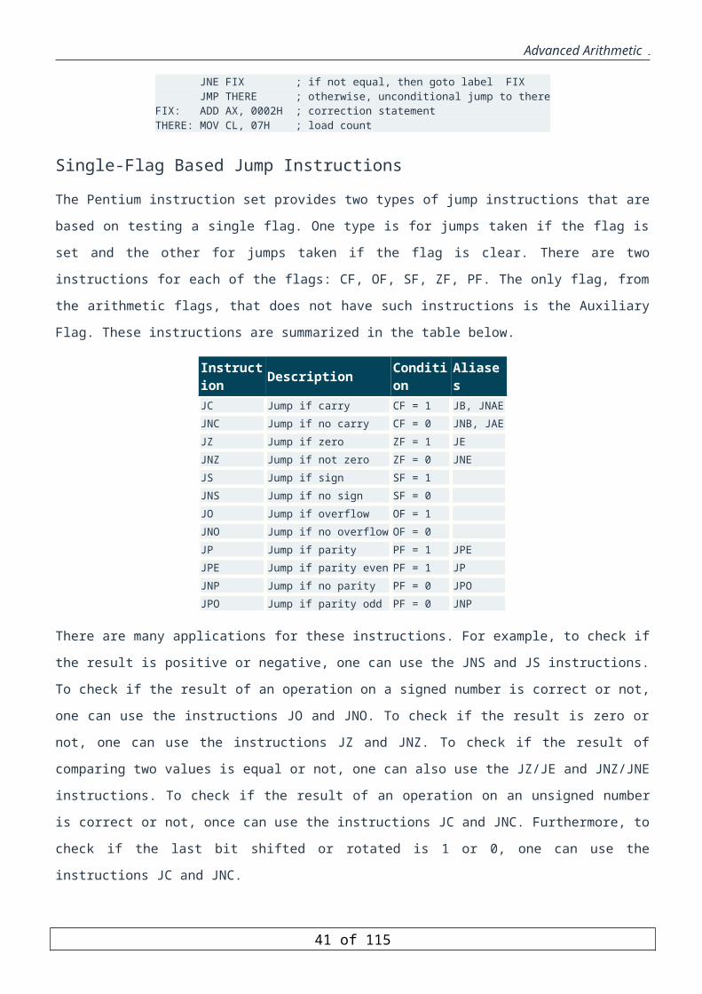
Advanced Arithmetic
Pentium Stack Instructions and Directives
Pentium has two very basic but powerful stack instructions: PUSH & POP
Instruction Operand Note
PUSH
r/m16r/m32immSreg
If (the size of operand is 32-bit) {SP=SP-4;SS:[SP]=operand (dword assignment)}If (the size of operand is 16-bit){SP=SP-2SS:[SP]=operand (word assignment)}
POP r/m16r/m32Sreg
POP CS is invalidIf (the size of operand is 32-bit)N=4If (the size of operand is 16-bit) N=2Read N bytes from memory at location SS:SP and store at operandOperand=SS:[SP]SP= SP + N
MASM provides us a special directive to initialize the size of the stack segment:
.STACK the size in bytes
The directive .STACK 200h in the beginning of your source code tells the assembler to set information in the
program that when the program runs it will initialize the content of SP to 512.
Stack Usage
The Stack and its instructions can be utilized for
preserving temporarily data and registers.
supporting procedure and interrupt mechanism.
passing parameters into procedures.
allocating local variables.
Pentium Advanced Stack Instructions
Instruction Operand Note PUSHF It pushes the rightmost 16-bit EFLAG register onto the stack.
POPF It pops up the 16-bit data from SS:[SP] and stores into the righmost 16-bit EFLAG register.
PUSHFD It pushes the content of EFLAGS register onto the stack. POPFD It pops up the 32-bit data from SS;[SP] and stores into EFLAGS register. PUSHA It is equivalent to instructions:
41 of 85

Advanced Arithmetic
Temp=SPPUSH AXPUSH CXPUSH DXPUSH BXPUSH TempPUSH BPPUSH SIPUSH DI
POPA It is complementary for PUSHA instruction. It pops up DI first, then SI, BP, skip for SP, pops up BX, DX, CX, and finally AX.
PUSHAD
It is 32-bit version of PUSHA instruction.Temp=ESPPUSH EAXPUSH ECXPUSH EDXPUSH EBXPUSH TempPUSH EBPPUSH ESIPUSH EDI
POPAD
It reverses a previous PUSHAD instruction, restoring the general registers to their values before the PUSHAD instruction was executed.POP EDIPOP ESIPOP EBPthrowaway=POP()POP EBXPOP EDXPOP ECXPOP EAX
The following examples illustrate some useful applications of the stack instructions.
Example 1: Assign DX:AX into EAX push DX push AX pop EAX
Example 2: Assign CS into DS push CS pop DS
Example 3: Set CF=PF=1 pushf pop AX or AX, 5 push AX popf For 8086, the equivalent code is LAHF or AH, 5 SAHF
42 of 85

Advanced Arithmetic
Procedures
In procedural paradigm, to solve a problem usually we use divide-and-conquer strategy. The problem is broken
down into many constituent parts. These parts are relatively independent and can be viewed as black boxes. Then,
using a procedural programming language such as C, Pascal, Basic, and Fortran, those components are
implemented as subroutines, procedures, or functions. These subroutines accept well-defined inputs, regardless
who supply the inputs, perform a certain action, and optionally return a specific result value.
By breaking down the program into many subroutines, it veils the complexity of the program so the designer or
programmer can focus on the overall flow of the program. In addition, maintaining the program becomes much
easier, and ultimately it increases the reusability. Furthermore, the developed subroutines may be used again to
develop other programs.
Inputs are passed to precedurs by either passing them by value or by reference. The inputs are passed by value
when the procedure is not going to change their content and hence only their values are passed to the procedure.
However, when it is required that the procedure changes the content of the inputs, then what is passed is the
addresses of the inputs, and this what is called passing by reference.
How does a Procedure work?
There are four steps that need to be accomplished in order to call and return from a procedure:
Save the return address
Procedure call
Execute procedure
Return execution to the saved return address.
As an illustration, Calling to and returning from a procedure may be depicted as:
Procedure call and return mechanism .CODE … lea AX, rtn1 ; AX=address of return point push AX ; save AX into the stack jmp subrtn ; goto the procedure part rtn1: ; return point …; program halts subrtn: … pop BX ; read the return address jmp BX ; go back to the return point
Assembly-language procedures are similar to functions,subroutines,and procedures in high-level languages such
as Java, C,FORTRAN,and Pascal. Two instructions control the use of assembly-language procedures. CALL
pushes the return address onto the stack and transfers control to a procedure, and RET pops the return address off
the stack and returns control to that location.
43 of 85
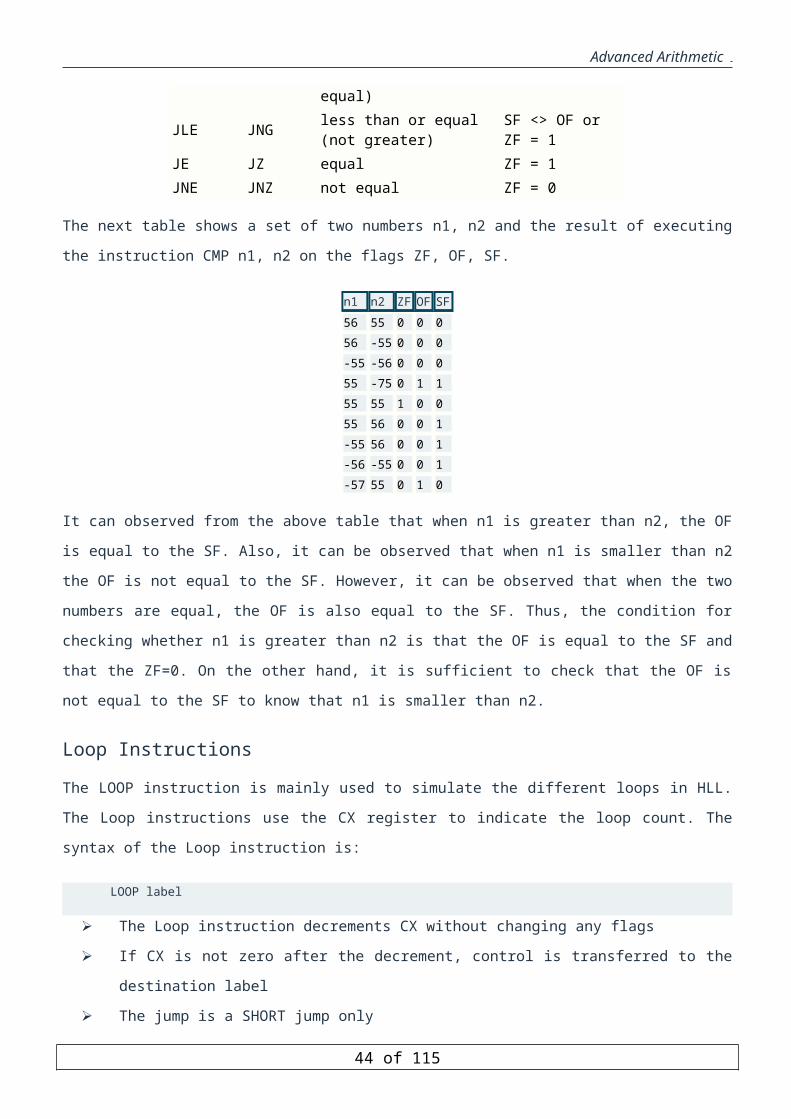
Advanced Arithmetic
Subroutine call and return instruction usage .CODE . . call subrtn ; code here that would be executed following the return . . ; program halts subrtn PROC . . ret subrtn ENDP
Instruction Operand Note
CALL label name Push IPIP= IP + displacement relative to next instruction
CALL r/m Push IPIP = [r/m]
CALL label name (FAR)
Push CSPush IPCS:IP=address of label name
CALL m (FAR) Push CSPush IPCS:IP= [m]
RET Pop IP
RET imm Pop IPSP = SP + imm
RET (FAR) Pop IPPop CS
RET imm (FAR) Pop IPPop CSSP = SP + imm
Assembler Directives for Procedures
MASM provides two directives to define procedures:PROC and ENDP. The PROC and ENDP directives mark
the beginning and end of a procedure.
Defining Subroutine
The basic syntax for PROC is:
label PROC [NEAR | FAR]..RET [constant]label ENDP
In a NEAR procedure, both calling and called procedures are in the same code segment.
Called and calling procedures are in two different segments in a FAR procedure.
PROC and ENDP do not actually generate any code; they are directives, not instructions.
PROC and ENDP control the type of RET instruction used in a given subroutine.
If the operand to a PROC directive is NEAR then all RET instructions between that PROC directive and
the corresponding ENDP directive are assembled as near returns.
44 of 85

Advanced Arithmetic
If, on the other hand, the operand to a PROC directive is FAR, then all RET instructions within that
procedure are assembled as far return.
If the PROC directive is without any operand, the assembler automatically makes the procedure near or
far according to the memory model selected with the .MODEL directive.
Tiny-, small-, and compact-model program have near calls.
Medium-, large-, and huge-model programs have far calls.
Example: TestSub is near-callable Example: TestSub is far-callable .MODEL SMALL . . . TestSub PROC . . ret TestSub ENDP
.MODEL LARGE . . . TestSub PROC . . ret TestSub ENDP
Preserving Registers
One of the crucial issues in developing a stable and robust assembly language program is conflict of using register
between calling program and the called procedure. Because registers are processor's resources shared together by
calling program and the called procedure, then it makes sense that many times called procedure may modify the
content of some registers that are still being used by the calling program. The customary solution is to preserve
registers before the procedure performs its main job and to restore the register values after its completion. There
are two ways to preserve registers:
The procedure tackles everything. In the beginning, the procedure preserves registers and at the end
before the procedure returns, it recovers all original registers values.
The calling program presupposes that the procedures do not preserve the registers. The calling program
takes all responsibilities to preserve and to restore the registers.
However, employing the register preservation carelessly causes performance degradation considerably. It could
be time-consuming and it increases the amount of code. Thus, it is the programmer's responsibility to find the best
trade-off.
Parameter Passing
Not like high level language, Assembly language has no support to define a list of parameters of a subroutine.
This deficiency fortunately gives full flexibility to the programmers to arrange the way to pass parameters. There
are three different ways of parameter passing:
Using general purpose registers.
Using global (static) variabels.
Using stack.
45 of 85
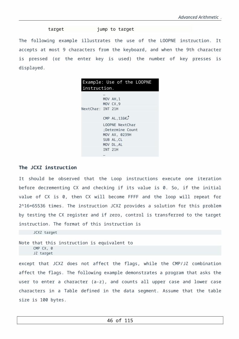
Advanced Arithmetic
Using general purpose registers
The programmer must place first the necessary parameters into a set of registers before invoking the subroutine
using call instruction. To avoid confusion, it suggests to comment carefully each subroutine as to which
parameters it expects to receive and in which registers they should be placed. The following is an example of call-
by-reference subroutine using register method.
Example: The subroutine to swap 2 byte-variables ;INPUT: SI and DI = the pointers to the variables OUTPUT: SWAP PROC
xchg AL, [SI]xchg AL, [DI]xchg AL, [SI]ret
SWAP ENDP
The following is an example of call-by-value subroutine using register method.
Example: The subroutine to display a byte as a Hexadecimal number ;INPUT: DH OUTPUT: ;This subroutine displays the hexadecimal digits of the content of DH. ;AX and BX are preserved. BX and DL are destroyed. HEX PROC
push AXpush DSmov AX, CSmov DS, AX ; DS == CSmov AL, DH ; make a copyshr AL, 4mov BX, OFFSET Hexdigitxlatb ; equiv. to mov AL, [BX+AL]mov DL, ALmov AH, 2int 21hmov AL, DHand AL, 0Fhxlatbmov DL, ALmov AH, 2int 21hmov DL,'h'mov AH, 2int 21hpop DSpop AXret
HexDigit DB '0123456789ABCDEF' HEX ENDP
Advantages of the register method: Convenient, easier and Faster
Disadvantages:
Only a few parameters can be passed using the register method.
Only a small number of registers are available.
Often these registers are not free. In fact, freeing them by pushing their values onto the stack negates the
second advantage.
Using global (static) variables
46 of 85

Advanced Arithmetic
The programmer must place first the necessary parameters into a set of global (public static) variables before
invoking the subroutine using call instruction.
Advantages of the global variables method: convenient, easier and many parameters can be passed.
Disadvantages
Actually this method violates the essence of modular programming paradigm.
Hard and difficult to maintain the program because of the dependencies on global variables.
Many times the global variables creates unprecedented side effects especially in distributed processes.
Try to avoid to use this method as much as possible. Only use in cases as the last solution.
Stack Method: Passing Arguments on the Stack
The programmer must first push the necessary parameters to the subroutine onto the stack. The subroutine then
may access each parameter as an offset from BP.
This method is used widely by most of programming languages such as Fortran, C, Pascal, Basic.
There are two important issues must be considered before using stack method:
The "naming convention" specifies how or if the assembler alters the name of an identifier before
placing it into an object file.
The "calling convention" determines how the assembler implements a call to a procedure and how the
procedure returns to the caller.
MASM supports the following different conventions.
Convention C SYSCALL STDCALL BASIC/FORTRAN/PASCAL Leading underscore X X Capitalize all X Arguments pushed left to right X Arguments pushed right to left X X X Caller stack cleanup X X * :VARARG X X X
Naming Conventions
"Naming convention" refers to the way the assembler stores the names of identifiers. The first two rows of the
above Table show how each language type affects symbol names. SYSCALL leaves symbol names as they appear
in the source code, but C and STDCALL add an underscore prefix. PASCAL, BASIC, and FORTRAN change
symbols to all uppercase.
The following list describes how these naming conventions affect a variable called Big Time in your source code:
47 of 85
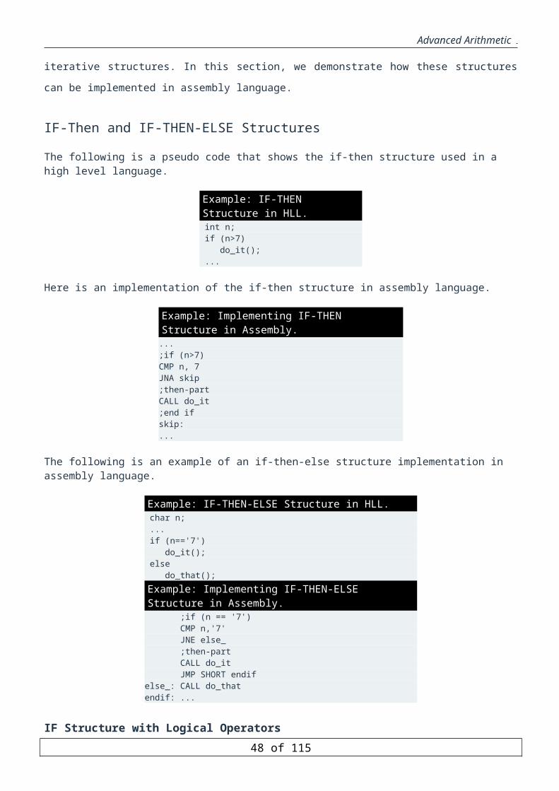
Advanced Arithmetic
Langtype Specified Characteristics SYSCALL Leaves the name unmodified. The linker sees the variable as Big Time.
C, STDCALL The assembler adds a leading underscore to the name, but does not change case.The linker sees the variable as _Big Time.
PASCAL, FORTRAN, BASIC Converts all names to uppercase. The linker sees the variable as BIG TIME.
The C Calling Convention
Specify the C language type for assembly-language procedures called from programs that assume the C calling
convention. Note that such programs are NOT NECESSARILY WRITTEN IN C, since other languages can
mimic C conventions. With the C calling convention, the caller pushes arguments from right to left as they appear
in the caller’s argument list. The called procedure returns without removing the arguments from the stack. It is the
caller’s responsibility to clean the stack after the call, either by popping the arguments or by adding an appropriate
value to the stack pointer SP.
Suppose you want to implement the following pseudo-code:i = 25; j = 4; Test(i, j, 1);
Then, the assembly language code fragment looks like:mov i, 25 mov j, 4 push 1 push _j push _i call _Test add sp, 6
As seen above, the rightmost parameter, 1, being pushed first, then _j, and finally _i. Upon return from a
subroutine, the parameters that were pushed on the stack are still there, but are no longer of any use.
Consequently, immediately following each subroutine call, the calling code adjusts the stack pointer back to the
value it contained before the parameters were pushed, thereby discarding the parameters. The following figure
shows what the stack looks like just before the first instruction in subroutine Test is executed:
48 of 85
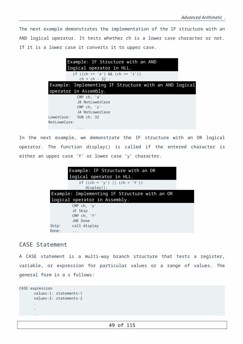
Advanced Arithmetic
The subroutine then can access parameters on the stack relative to the BP register. For example, suppose the
subroutine Test in the previous example is:
Example: Accessing parameters on the stack _Test PROC
push BPmov BP, SPmov AX, [BP + 4] ;get _iadd AX, [BP + 6] ;add _jsub AX, [BP + 8] ;subtract parm 3 (1) from sumpop BPret
_Test ENDP
The following figure shows the state of the stack after PUSH BP and MOV BP, SP are executed.
The STDCALL Calling Conventions
Argument passing order for STDCALL is similar as the C calling convention.
The caller pushes the arguments from right to left.
The called procedure cleans the stack if the procedure does not accept a variable number of
arguments. Otherwise, the caller must remove the parameters from the stack after the call.
Example: Subroutine Test using STDCALL Convention
_Test PROCpush BPmov BP, SPmov AX, [BP + 4] ;get _iadd AX, [BP + 6] ;add _jsub AX, [BP + 8] ;subtract parm 3 (1) from sumpop BPret 6
_Test ENDP
The Pascal Calling Convention
This convention pushes arguments left to right so that the last argument is lowest on the stack,and it requires that
the called subroutines remove arguments from the stack.
49 of 85

Advanced Arithmetic
Local Variables
We have known how to use stack as an interface for passing parameters to the subroutine. The idea is to use BP
register as an anchor point to access the passed parameters using instructions like mov r/m, [BP + n].
When a subroutine is invoked, a new environment is created. In his newly created environment, new local
variables are defined, while the values of the previous environment must be preserved. Variables for holding
intermediate values during a computation like expression evaluation may also be needed. Like return addresses,
these local variables are dynamic data whose values must be preserved over the lifetime of the procedure, but not
beyond its termination. At the termination of the procedure, the current environment disappears and the previous
environment must be restored.
Space for local variables can be reserved by subtracting the required number of bytes from SP.
Since the portion of the stack holding local variables is at a lower address than BP, negative offsets from
BP are used to address local variables.
In the following example, assume that the size of char is 2 bytes, the size of int is 4 bytes, STDCALL convention
is used.
Pseudo-code (Java-like) Assembly Language
void Test(char i, char j){char b;int k; k = 9;b = i;}
_Test PROCpush BPmov BP, SPsub SP, 6push AXmov DWORD PTR [BP - 6], 9mov AX, [BP + 4]mov [BP - 2], AXpop AXmov SP, BPpop BPret 4_Test ENDP
50 of 85
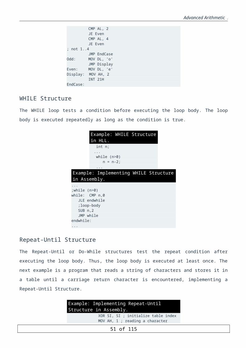
Advanced Arithmetic
Macros and Conditional Assembly
We have seen that procedures are extremely useful for implementing modular program design techniques.
In this unit, we discuss another mechanism to modularize program code based on macros. Simply put, a macro is
a sophisticated text subsitution mechanism. The objectives of this unit are:
To discuss macro definition and expansion
To explain how blocks of statements can be repeated
To describe conditional assembly directives
To describe how to define a macro library
To explore the performance tradeoffs associated with macros and procedures
Macro Definition and Invocation
A macro is a block of text (code, data, etc.) that has been given a name (called a macro name ). When the
assembler encounters that name in a program, the block of text associated with the macro name is subsituted. This
process is referred to as macro expansion .
Assemblers provide three directives to support macro substitutions: =, EQU, and MACRO.
The directives = and EQU can be used for constant substitution during assembly time. For example, we can write
CLASS_SIZE = 90or CLASS_SIZE EQU 90
Both statements cause 90 to be textually substituded for CLASS_SIZE.
The difference between = and EQU directives is that the = directive allows redifinition later on, while the
constants defined by EQU cannot be redefined. However, both these directives are not useful for general text
subsitution.
The syntax of macro definition is
macro_name MACRO [parameter1, parameter2, ...] macro body ENDM
Here macro_name is the user-supplied name for the macro. The pseudo-ops MACRO and ENDM indicate the
beginning and end of the macro definition. In the MACRO directive, the parameters are optional (as indicated by
the square brackets []).
To invoke or call a macro, use the macro_name and supply the necessary parameter values. This causes a macro
expansion, i.e. it copies the macro body into the program at the position of the invocation, just as if the user has
typed them in. The format for invoking a macro is
51 of 85

Advanced Arithmetic
macro_name [argument1, argument2, ...]
During macro expansion, the assembler replaces each parameter in the macro body by its corresponding
argument.
Position of Macro Definition
One use of macros is to create new instructions. For example, we know that the operands of a MOV instruction
can't both be word variables, but we can get arond this restriction by defining a macro to move a word into a
word.
Example: Define a macro to move a word into a word. MOVW MACRO WORD1, WORD2 PUSH WORD2 POP WORD1 ENDM
Example: Invoke the macro MOVW to move B to A, where A and B are word variables. MOVW A, B
To expand this macro, the assembler would copy the macro statement into the program at the position of the call,
replacing the occurence of WORD1 with A and WORD2 by B. The result is
PUSH BPOP A
The 8086 processor does not allow specification of shift count great than 1 as an immediate value. Next, we will
write a shift left macro that allows that. We will call this macro SHLI.
Example: Define a macro to shift left an operand to the left by an immediate value that can be greater than 1. SHLI MACRO operand, count MOV CL, count SHL operand, CL ENDM
Example: Invoke the macro SHLI to shift left regiter AX by 6 bits. SHLI AX, 6
This macro invocation will be expanded into the following code:
MOV CL, 6SHL AX, CL
Macros versus Procedures
Macros are similar to procedures in some respects. Both improve program productivity by aiding in the
development of modular source code. There are, however, some significant differences between them.
Parameter passing
52 of 85

Advanced Arithmetic
Parameter passing in a macro invocation is similar to that in a procedure call of a high-level language. The
arguments are listed as part of a macro call. Parameter passing in a procedure call often involves the stack. The
number of stack operations in preparation for a procedure call grows in direct proportion to the number of
parameters passed. This, in addition to the call/ret overhead, increases the overhead and affects the performance.
Macros avoid this overhead by text substitution but increase the space requirement.
Types of parameters
Since a macro is a text substitution mechanism, a variety of parameter types can be passed. For example, we can
write a macro
shift MACRO opcode, operand, count MOV CL, count opcode operand, CL
ENDM
and invoke it as
shift SAL, AX, 3
which results in the following macro expansion
MOV CL, 3SAL AX, CL
Here opcode is the instruction mnemonic, which can be an mnemonic in the shift and rotate family of instructions.
Thus, the same macro can be used with all of the shift and rotate family of instructions on bytes, words, and
doublewords that are either located in a register or memory. Clearly, such parameter types cannot be passed to a
procedure.
Invocation mechanism
Macro invocation is done at assembly time by text substitution. However, procedure invocation is done at run
time by transferring control to the procedure. This leads to the following tradeoff. Macros tend to increase the
length of the executable code due to macro expansions. This leads to increased assembly time. Macro expansion
also creates a nuisance at debuuging time--repeatedly looking at part of code (macro expansions) that you know
works correctly. Procedures avoid these problems by transferring control to the procedure code. In debugging, the
proecdure call can be skipped.
In summary, the tradeoffs are that using macros results in faster execution of the code. However, macros result in
increased memory space due to macro expansions. Procedures save space, as only one copy of the procedure is
kept. However, procedure invocation overhead (to pass parameters via the stack and for call/ret) increases the
execution time. Note that macro invocation causes assembly-time overhead but not run-time overhead. The
advantages and disadvantages associated with macros and procedures can be summarized into the following table:
Type of Overhead Procedure Macro
53 of 85

Advanced Arithmetic
memory space lower higher Execution time higher lower Assembly time lower higher
When are macros better
Given the state of modern technology, this time versus space tradeoff is a major factor in preferring one over the
other. The choice between macros and procedures depends on the application requirements. For typical
applications, it is recommended to use procedures except in some special situations identified next:
Macros are useful in defining macro-instructions that extend the instruction set of a processor. For
example, suppose that we want to write a program module to multiply an operand by 16. We will do this
by both a macro and a procedure to see the difference in the overhead.
Example: Write a macro mult16 to multiply an operand by 16 using shift instructions. mult16 MACRO operand MOV CL, 4 SHL operand, CL ENDM
Example: Write a procedure times16 to multiply an operand by 16. Assume that the operand is pushed on the stack. times16 PROC PUSH BP MOV BP, SP PUSH AX MOV AX, [BP+4] MOV CL, 4 SAL AX, CL MOV [BP+4], AX POP AX POP BP RET times16 ENDP
This procedure can be invoked to multiply a word variable count by 16 as
PUSH countCALL times16POP count
The overhead involved is substantial. Clearly, this is an impractical proposition. Macros are useful when text
substitution is the only way available. Consider the following example. Suppose that we want to preserve the
content of registers BX, CX, DX, SI, DI, and BP across procedure calls. We could use PUSHA and POPA, but
these instructions save and restore the AX register as well. But, we want to return a result in AX. We can
conveniently do this by the following two macros:
save_regs MACRO restore_regs MACRO PUSH BP POP BX PUSH DI POP CX PUSH SI POP DX PUSH DX POP SI PUSH CX POP DI PUSH BX POP BP ENDM ENDM
54 of 85

Advanced Arithmetic
It is not possible to write a procedure to do the same.
Labels in Macros
A macro with a loop or decision structure contains one or more labels. If such a macro is invoked more than once
in a program, a duplicate label appears, resulting in an assembly error. This problem can be avoided by using
local labels in the macro.
Labels in Procedures
Label problems are avoided in procedures, as the scope of a label declared within a procedure body is limited to
that procedure. The LOCAL directive is provided by the assembler to declare labels in a macro local to that
macro. The syntax of using local directive is:
LOCAL local-label1 [, local-label2, ...]
Every time the macro is expanded, the assembler assigns different symbols to the labels in the list.
Position of Local Label Definition in Macros
Example: Write a macro to place the largest of two words in AX. GET_BIG MACRO WORD1, WORD2 LOCAL EXIT MOV AX, WORD1 CMP AX, WORD2 JG EXIT MOV AX, WORD2 EXIT: ENDM
Now, suppose that FIRST, SECOND, and THIRD are word variables. A macro invocation of the form
GET_BIG FIRST, SECOND
expands as follows:
MOV AX, FIRST CMP AX, SECOND JG ??0000 MOV AX, SECOND ??0000:
A later call of the form:
GET_BIG SECOND, THIRD
expands as follows:
MOV AX, SECOND CMP AX, THIRD JG ??0001 MOV AX, THIRD ??0001:
55 of 85
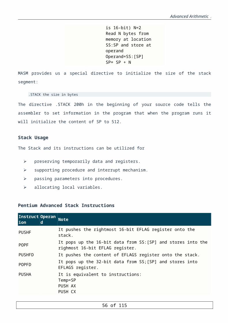
Advanced Arithmetic
Subsequent invocations of this macro or to other macros with local labels causes the assembler to insert labels ??
0002, ??0003, and so on into the program.
The labels that the assembler generates to replace the local labels are of the form ??XXXX, where XXXX is a
hexadecimal number between 0 and FFFFH. Thus, a program can have up to 2^16=65,536 local labels, a large
enough number for most programs.
Conflicts with Local Labels
To avoid conflicts with local labels, you should not use labels in your program that begin with ??.
Macro Expansion in the .LST File
The .LST file is one of the files that can be generated when a program is assembled. It shows assembly code and
the corresponding machine code, addresses of variables, and other information about the program. The .LST file
also shows how macros are expanded. We will demonstrate this by an example.
Example: The following program contains the MOVW macro and two invocations. TITLE PGM1: MACRO DEMO .MODEL SMALL MOVW MACRO WORD1, WORD2 PUSH WORD2 POP WORD1 ENDM .STACK 100H .DATA A DW 1, 2 B DW 3 MAIN PROC MOV AX, @DATA MOV DS, AX MOVW A, DX MOVW A+2, B ; dos exit MOV AH, 4CH INT 21H MAIN ENDP END MAIN
The next figure shows the file PGM1.LST. In this file, the assembler prints the macro invocations, followed by
their expansions (shown in boldface). The digit 1 that appears on each line of the expansions means that these
macros were invoked at the "top level"; that is, by the program itself. We will show later that a macro may invoke
another macro.
PGM1.LST
TITLE PGM1: MACRO DEMO.MODEL SMALLMOVW MACRO WORD1, WORD2 PUSH WORD2 POP WORD1 ENDM.STACK 100H
0000 .DATA 0000 0001 0002 A DW 1, 2
56 of 85

Advanced Arithmetic
0004 0003 B DW 3 0000 .CODE 0000 MAIN PROC 0000 B8 ---- R MOV AX, @DATA 0003 8E D8 MOV DS, AX
MOVW A, DX 0005 52 1 PUSH DX 0006 8F 06 0000 R 1 POP A
MOVW A+2, B 000A FF 36 0004 R 1 PUSH B 000E 8F 06 0002 R 1 POP A+2
; dos exit 0012 B4 4C MOV AH, 4CH 0014 CD 21 INT 21H 0016 MAIN ENDP
END MAIN
List Control Directives
There are several list control directives to specify the contents of the output listing (.LST) file. These directives
can appear anywhere in the language source code. Each directive will be in effect until replaced by another
directive. The following two directives control the source lines in the .LST file:
.LIST Allows listing of subsequent source lines (This is the default mode).
.XLIST Suppresses listing of subsequent source lines.
Example: We can suppress the contents of an include file as shown below. .XLIST ; suppress listing INCLUDE part0.inc .LIST ; restore listing
Macro list control directives
The assembler always lists the macro definistions in the .LST file. The following three list control directives
affect only macro invocation calls:
.LALL Enables listing of macro expansions. All source lines are listed, except those beginning with a
double semicolon.
.SALL Suppresses listing of all statements in macro expansions.
.XALL Lists only the source statements in a macro expansion that generate code or data. Statements
that do not generate code or data such as comments (EQU and =) are not listed. It also suppresses repeat
block directives and conditional assembly directives, that will be discussed later. (default option.)
Comments in Macros
Any comment that starts with ;; will appear only in the macro definition but not in macro expansions. Comments
that start with ; (i.e., the standard comments) appear in macro expansions as well.
Example: Suppose that the MOVW macro is rewritten as ahown below. Show how the following macro invocations would appear in a .LST file.
57 of 85
Advanced Arithmetic
MOVW MACRO WORD1, WORD2 ; moves source to destination ;; uses the stack PUSH WORD2 POP WORD1 ENDM .XALL MOVW DS,CS .LALL MOVW P,Q .SALL MOVW AX,[SI]
The above macro invocations would appear in a .LST file as follows:
.XALL MOVW DS,CS PUSH WORD2 POP WORD1 .LALL MOVW P,Q ; moves source to destination PUSH Q POP P .SALL MOVW AX,[SI]
Assembly errors during macro expansion
If the assembler finds an error during macro expansion, it indicates an error at the point of the macro invocation;
however, it is more likely that the problem is within the macro itself. To find where the mistake really is, you
need to inspect the macro expansion in the .LST file.
Nested Macros
Macros can be nested, i.e., a macro may invoke another macro. When macros are expanded, the nesting level is
shown on the left of each expanded statement.
Example: Let us write a macro to copy a string using two other macros to save and restore registers. SAVE_REGS MACRO R1, R2, R3 PUSH R1 PUSH R2 PUSH R3 ENDM RESTORE_REGS MACRO R1, R2, R3 POP R1 POP R2 POP R3 ENDM COPYS MACRO SOURCE, DESTINATION, LENGTH SAVE_REGS CX, SI, DI LEA SI, SOURCE LEA DI, DESTINATION CLD MOV CX, LENGTH REP MOVSB RESTORE_REGS DI, SI, CX ENDM
Example: Show the code that the assembler will generate when it encounters the macro invocation COPYS STRING1, STRING2, 15. PUSH CX
58 of 85

Advanced Arithmetic
PUSH SI PUSH DI LEA SI, STRING1 LEA DI, STRING2 CLD MOV CX, 15 REP MOVSB POP DI POP SI POP CX
Recursive Macros
A macro may invoke itself; such macros are called recursive macros.
Macro Library
The macros that a program invokes can be stored in a file. This makes it possible to create a library file of useful
macros and use it using the INCLUDE pseudo-op. For example, suppose the file's name is MACROS, on a disk
in drive A. When the assembler encounters the pseudo-op
INCLUDE A:MACROS
in a program, it copies all the macro definitions from the file MACROS into the program at the position of the
INCLUDE statement.
Position of INCLUDE Statement
The INCLUDE statement may appear anywhere in the program, as long as it precedes the invocation of its
macros.
Examples of Useful Macros
The following are examples of macros that are useful to have in a macro library.
Example: Write a macro to return to DOS. DOS_RTN MACRO MOV AH, 4CH INT 21H ENDM
The macro invocation is DOS_RTN
Example: Write a macro to display a carriage return and line feed. NEW_LINE MACRO MOV AH, 2 MOV DL, 0DH INT 21H MOV DL, 0AH INT 21H ENDM
The macro invocation is NEW_LINE
Example: Write a macro to display a character string such that the string is a macro parameter. DISP_STR MACRO STRING
59 of 85

Advanced Arithmetic
LOCAL START, MSG ; save registers PUSH AX PUSH DX PUSH DS JMP START MSG DB STRING, '$' START: MOV AX, CS MOV DS, AX MOV AH, 9 LEA DX, MSG INT 21H ; restore registers POP DS POP DX POP AX ENDM
Sample invocation: DISP_STR "This is a string"
When the DISP_STR macro is invoked, the string argument replaces the STRING parameter. Because the string
is being stored in the code segment, CS must be moved to DS.
Using a Macro Library
The preceding macros have been placed in file MACROS. In the following example, we will show how to use a
macro library in a program.
Example: Write a program that uses the macro library MACROS to display a message, go to a new line, and display another message. .MODEL SMALL .STACK 100H INCLUDE MACROS .CODE MAIN PROC DISP_STR "This is the first line" NEW_LINE DISP_STR "This is the second line" DOS_RTN MAIN ENDP END MAIN
Macro Operators
There are five operators to manipulate macros as shown in the next table.
Operator Meaning ;; Suppress comment operator & Substitute operator <> Literal-text string operator ! Literal-character operator % Expression evaluate operator
60 of 85

Advanced Arithmetic
We have already seen how the ;; operator works. We will briefly discuss next the remaining four operators.
Substitute Operator (&)
The substitute operator (&) forces the assembler to substitute a parameter with the actual argument. The syntax is
&name
where name is the value of the argument in the macro call. The & operator is typically used to concatenate one or
more parameters with other text.
Example: We can write a macro to sort two numbers num1 and num2 that works on a 16-bit signed or unsigned numbers. Sort2 MACRO cond, num1, num2 LOCAL done PUSH AX MOV AX, num1 CMP AX, num2 J&cond done XCHG AX, num2 MOV num1, AX done: POP AX ENDM
In this macro, the cond parameter specifies the relationship of num2 relative to num1. For example, to sort two
unsigned numbers value1 and value2 such that value1 >= value2, we can invoke the macro as
sort2 AE, value1, value2
which causes the following macro expansion: sort2 AE, value1, value2 PUSH AX MOV AX, value1 CMP AX, value2 JAE ??0000 XCHG AX, value2 MOV value1, AX ??0000: POP AX
If value1 and value2 are signed numbers, this macro should be invoked as sort2 GE, value1, value2
which generates the JGE conditional jump instruction in the macro expansion. The substitute operator is also
useful to force the assembler to substitute a parameter inside a quoted string. This is illustrated in the following
example.
Example: Write a macro to define an error message for informing the user when the input number is out of range. range_error MACRO number, variable err_msg&number DB "&variable: out of range", 0 ENDM
When the macro is invoked as
range_error 1, Assignment_mark
61 of 85

Advanced Arithmetic
it will be expanded as
err_msg1 DB "Assignment_mark: out of range",0
Literal-Text String Operator (<>)
The literal-text string operator (< >) informs the assembler that the enclosed text should be treated as a single
string rather than separate arguments. The syntax is
< text >
The text is treated as a single argument even if it contains parameter separators. Some typical parameter
separators are commas, spaces, tabs, etc. The assembler removes the angle brackets and uses text as the argument.
Example: Modify the range_error macro defined before to inform the user of the correct range along with the error message. range_error1 MACRO number, variable, range err_msg&number DB "&variable: out of range", 0 range_msg&number DB "Correct range is &range", 0 ENDM
When we invoke this macro as
range_error1 1, < Assignment mark >, < 0 to 25 >
the macro expansion will look like this
err_msg1 DB "Assignment mark: out of range", 0 range_msg1 DB "Correct range is 0 to 25", 0
This operator can also be used to force the assembler to treat a character literally by removing its default special
meaning. For example, <;> passes ; as an argument without treating it as the comment operator. This can also be
done using the literal-character operator, as will be seen next.
Literal-Character Operator (!)
The literal-character operator (!) preceding a character forces the assembler to treat the character literally
without its default special meaning. The syntax is
!character
Thus, !; is equivalent to <;>. The following example shows an instance where this operator is useful.
Example: Consider the macro defined below. range_error2 MACRO number, variable, range err_msg&number DB "&variable: out of range - &range", 0 ENDM
62 of 85
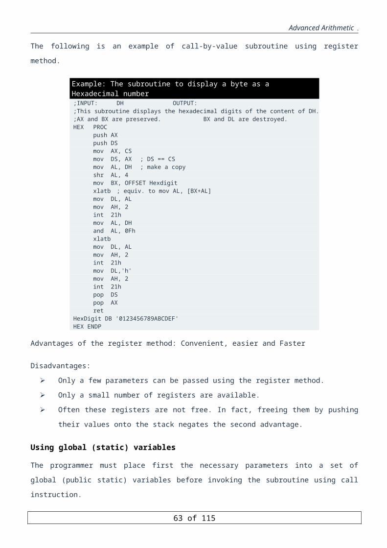
Advanced Arithmetic
We can invoke this in .DATA part as
range_error2 3, mark, < can!'!'t be !> 100 >
to create the error message
err_meg3 DB "mark: out of range - cant''t be > 100", 0
Note that if we didn't use the ! operator in the third argument, the assembler would have interpreted the third
argument as < can''t be >.
Successive Single Quotes
Note that two successive single quotes will produce a single quote in the output.
Expression Evaluate Operator (%)
The syntax of the expression evaluate operator (%) is
%expression
The expression is evaluated and its value is used to replace the expression itself. Typically, this operator is used to
provide an argument in a macro call.
Example: Consider a macro to allocate and initialize an array of a given size. Assume that the macro receives the array name and size, element size (B for byte, W for word, ...), and the initial value. init_array MACRO element_size, name, size, init_value name D&element_size size DUP (init_value) ENDM
To reserve space for an integer array of 47x7 (marks) and initialize it to -1, we can call the macro as:
init_array W, marks, %47*7, -1
The macro call will be expanded as
marks DW 329 DUP (-1)
Repeat Block Directives
Introduction
There are four directives to repeat a block of statements -- REPT , WHILE , IRP , and IRPC . These directives can be used both inside and outside a macro definition. They are mostly used to define and initialize variables in a data segment.
Each directive identifies the beginning of a block of statements and ENDM indicates the end of a repeat block. We will briefly discuss next these four directives.
REPT Directive
The REPT directive can be used to repeat a block of statements. Its syntax is
63 of 85

Advanced Arithmetic
REPT expression statments ENDM
When the assembler encounters this macro, the statements in the macro body are repeated a number of times
equivalent to the value of the expression. It is important to note that expression must evaluate to a constant at
assembly time.
REPT Macro Invocation
A REPT macro may be invoked by placing it in the program at the point that the macro's statements are to be
repeated. Another way to invoke a REPT macro is to place it in an ordinary macro and invoke that macro.
Example: Write a macro to initialize a block of memory to the first N integers. BLOCK MACRO N K=1 REPT N DW K K=K+1 ENDM ENDM
To declare a word array A and initialize it to the first 100 integers, we can place the following statements in the
data segment:
A LABEL WORD BLOCK 100
Invocation of the BLOCK macro initializes K to 1 and the statements inside the REPT macro are assembled 100
times. The first time, DW 1 is generated and K is incremented to 2; the second time, DW 2 is generated and K
becomes 3; .... the 100th time, DW 100 is generated and K becomes 101. The final result is equivalent to
A DW 1 DW 2 DW 3 . . . DW 100
Example: Write a macro to initialize an n-word array to 1!, 2!, ..., n!. FACT MACRO N M=1 F=1 REPT N DW F M=M+1 F=M*F ENDM ENDM
To declare a word array B of the first 5 factorials, the data segment can contain
B LABEL WORD FACT 5which will be expanded to B DW 1 DW 2
64 of 85

Advanced Arithmetic
DW 6 DW 24 DW 120
WHILE Directive
The WHILE directive can also be used to repeat a block of statements. Its syntax is
WHILE expression statments ENDM
The statments in the macro body are repeated until the expression evaluates to false (zero). The expression is
evaluated before each iteration of the macro body.
Example: Write a macro to initialize a block of memory to the first N integers. BLOCK2 MACRO N K=1 WHILE K LE N DW K K=K+1 ENDM ENDM
The macro invocation shown below
C LABEL WORD BLOCK2 5
will expand as follows
C DW 1 DW 2 DW 3 DW 4 DW 5
IRP Directive
The IRP (iteration repeat) directive provides a means of supplying a variable parameter to each iteration of a
repeat block. It syntax is
IRP parameter, < argument1 [, argument2, ...] > statments ENDM
The arguments are given as a list separated by commas. Note that the angle brackets are part of the syntax and are
required. During the first iteration, argument1 is assigned to the parameter for use in the block of repeat
statements; during the second iteration, argument2 is assigned, and so on. Therefore, the argument list specifies
both the number of iterations and the actual values to be used in each iteration.
Example: Write a macro to save and restore an arbitrary number of registers. SAVE_REGS MACRO REGS RESTORE_REGS MACRO REGS IRP D, <REGS> IRP D, <REGS> PUSH D POP D ENDM ENDM
65 of 85
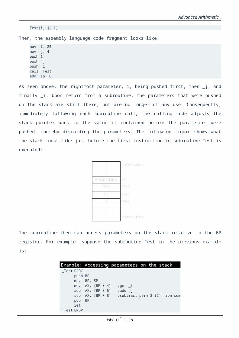
Advanced Arithmetic
ENDM ENDM
To save registers AX, BX, CX, DX, we can write
SAVE_REGS < AX, BX, CX, DX >
which will be expanded into
PUSH AX PUSH BX PUSH CX PUSH DX
To restore these registers, write
RESTORE_REGS < DX, CX, BX, AX >
IRPC Directive
The IRPC (iteration repeat with character substitution) directive is similar to the IRP directive. The difference is
in how the variable parameter values are specified. Its syntax is
IRPC parameter, string statments ENDM
The statements in the macro body are repeated once for each character in string. Like in the IRP directive, string
specifies the number of iterations as well as the character to be used in each iteration.
Example: Write a macro to display a string in upper case. DSTRU MACRO string MOV AH, 2 IRPC char, < string > LOCAL DISP MOV DL, "&char" CMP DL, "Z" JB DISP CMP DL, "a" JB DISP CMP DL, "z" JA DISP SUB DL, 20H DISP: INT 21H ENDM ENDM
Note that the angle brackets around the string argument in the IRPC macro are needed to allow for spaces in the
string. Also, it is important to note here that the LOCAL definition has to be in the IRPC macro body and not in
the DSTRU macro body. The macro invocation DSTRU Hello will produce the macro expansion as shown in the
next figure.
Expansion of the macro invocation DSTRU Hello
dstru Hello 1 MOV AH, 2 2 MOV DL, "H"
66 of 85
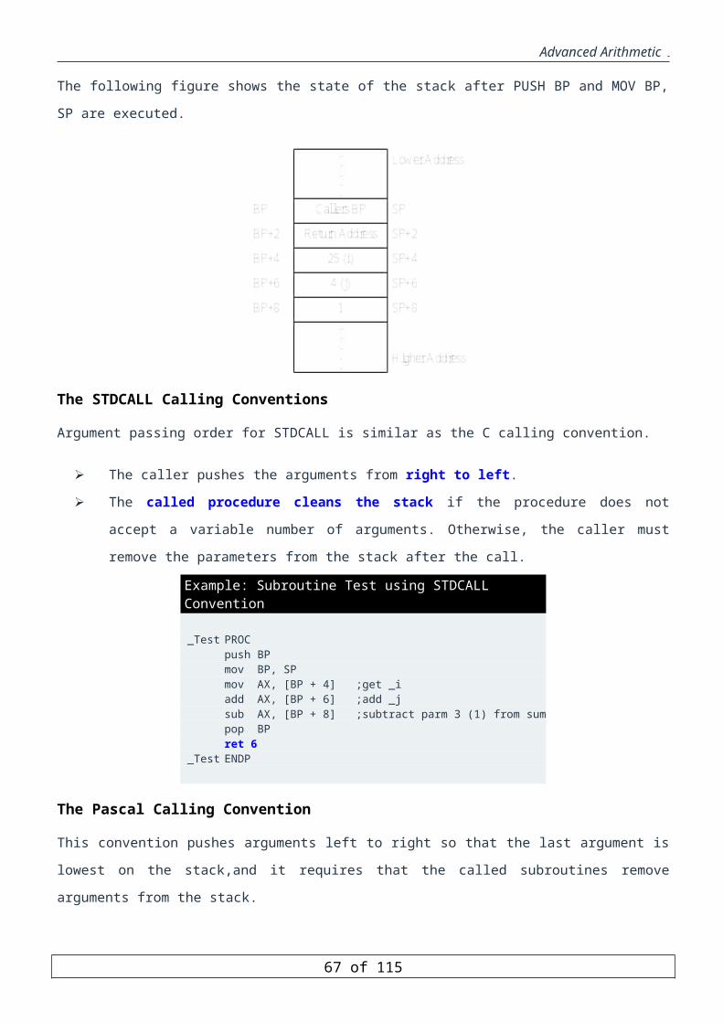
Advanced Arithmetic
2 CMP DL, "Z" 2 JB ??0000 2 CMP DL, "a" 2 JB ??0000 2 CMP DL, "z" 2 JA ??0000 2 SUB DL, 20H 2 ??0000: INT 21H 2 MOV DL, "e" 2 CMP DL, "Z" 2 JB ??0001 2 CMP DL, "a" 2 JB ??0001 2 CMP DL, "z" 2 JA ??0001 2 SUB DL, 20H 2 ??0001: INT 21H 2 MOV DL, "l" 2 CMP DL, "Z" 2 JB ??0002 2 CMP DL, "a" 2 JB ??0002 2 CMP DL, "z" 2 JA ??0002 2 SUB DL, 20H 2 ??0002: INT 21H 2 MOV DL, "l" 2 CMP DL, "Z" 2 JB ??0003 2 CMP DL, "a" 2 JB ??0003 2 CMP DL, "z" 2 JA ??0003 2 SUB DL, 20H 2 ??0003: INT 21H 2 MOV DL, "o" 2 CMP DL, "Z" 2 JB ??0004 2 CMP DL, "a" 2 JB ??0004 2 CMP DL, "z" 2 JA ??0004 2 SUB DL, 20H 2 ??0004: INT 21H
67 of 85

Advanced Arithmetic
Conditional Assembly
Introduction
Conditional directives may be used to assemble certain statements and exclude others. They may be used
anywhere in the assembly program, but are most often used inside macros. The general syntax of conditional
assembly directives is
Conditional Tstatements [ELSE Fstatements] ENDIF
Each conditional assembly directive ends with an ENDIF and there can be an optional ELSE clause present. If
Conditional evaluates to true, the Tstatments are assembled, otherwise Fstatements are assembled if the ELSE
clause is present. The next table gives the forms of the most useful conditional directives and what is required for
them to be evaluated as true.
Form TRUE IF IF exp Constant expression exp is nonzero. IFE exp Constant expression exp is zero. IFB < arg > Argument arg is missing (blank). Angle brackets are required. IFNB < arg > Argument arg is not missing (not blank). IFDEF sym Symbol sym is defined in the program (or declared as EXTRN). IFNDEF sym Symbol sym is not defined or EXTRN. IFIDN < str1 > < str2 > Strings str1 and str2 are identical (Case sensitive). IFIDNI < str1 > < str2 > Strings str1 and str2 are identical (Case insensitive). IFDIF < str1 > < str2 > Strings str1 and str2 are different (Case sensitive). IFDIFI < str1 > < str2 > Strings str1 and str2 are different (Case insensitive).
IF and IFE Directives
The syntax of the IF and IFE directives is
IF expression IFE expression
The IF directive assembles the then part if the expression evalues to true (nonzero). The IFE directive is the IF
counterpart and assembles the then part if the expression is false (zero). The next table shows some operators that
can be used in an expression.
Operator Type Operators Arithmetic +,-,*,/,mod,unary + and - Relational EQ, GE, GT, LE, LT, NE Logical NOT, AND, OR, XOR
68 of 85

Advanced Arithmetic
Example: Write a macro to define a block of memory words with N entries, consisting of the first K integers, followed by N-K zero words. BLOCK MACRO N, K I=1 REPT N IF K+1-I DW I I=I+1 ELSE DW 0 ENDIF ENDM ENDM
The following macro invocation A LABEL WORD BLOCK 10, 5
will produce the following statements A DW 1 DW 2 DW 3 DW 4 DW 5 DW 0 DW 0 DW 0 DW 0 DW 0
Example: Write a macro to exchange two memory operands such that the two operands can be either byte or word operands. MXCHG MACRO operand1, operand2 IF (TYPE operand1) NE (TYPE operand2) %OUT Operands of MXCHG do not match. ELSE IF (TYPE operand1) EQ 1 ; BYTE operands XCHG AL, operand1 XCHG AL, operand2 XCHG AL, operand1 ELSE ; WORD operands XCHG AX, operand1 XCHG AX, operand2 XCHG AX, operand1 ENDIF ENDIF ENDM
The TYPE operator returns the number of bytes reserved for the operand in memory. The next table shows the
values returned by the type operator.
Type of Memory Operand Value Returned BYTE 1 WORD 2 DWORD 4 QWORD 8 NEAR FFFFH FAR FFFEH Constant 0
69 of 85

Advanced Arithmetic
The %OUT directive is used for displaying text on the screen. It syntax is
%OUT text
where text can contain any character. This directive is useful for displaying error or warning messages during the
assembly process.
IFDEF and IFNDEF Directives
The syntax of IFDEF and IFNDEF directives is
IFDEF symbol IFNDEF symbol
If symbol is defined (IFDEF) or not defined (IFNDEF), the conditional block of statements is assembled. A
common use of these directives is to customize code for a particular processor.
Example: Write a macro to save all registers on the stack. PUSHALL MACRO IFNDEF PROC_TYPE PROC_TYPE EQU 8086 ENDIF IF PROC_TYPE EQ 8086 PUSH AX PUSH BX PUSH CX PUSH DX PUSH SI PUSH DI PUSH BP PUSH SP ELSE PUSHA ENDIF ENDM
In the above example, the assembly time variable PROC_TYPE is used to identify the processor type. The /D
option (e.g. /D PROC_TYPE=486) can be used to generate code targeted for a particular processor. If the
processor type is not specified on the assembly command line (i.e., the /D option is not specified), the default
8086 version is generated.
For 80186 or later processors, the PUSHA instruction pushes all registers (AX, BX, CX, DX, SI, DI, BP, and SP)
onto the stack. However, there is no such instruction for the 8086 processor, and we have to push each register
individually.
IFB and IFNB Directives
The syntax of the IFB and IFNB directives is
IFB < argument > IFNB < argument >
70 of 85
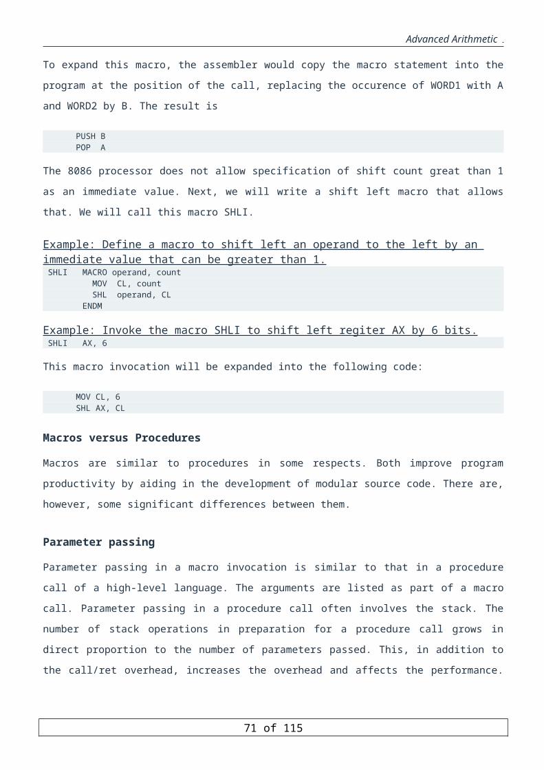
Advanced Arithmetic
Note that the angle brackets are required. The IFB directive assembles the then part if the argument is blank. The
IFNB directive assembles if the argument is not blank. These directives are useful to test the presence as well as
the number of arguments specified in a macro call.
Example: Write a macro READ MACRO BUF, LEN that either reads a string into the byte array BUF of length LEN (if both arguments are present), or reads a single character into AL (if both arguments are missing). READ MACRO BUF, LEN ; BUF = STRING BUFFER ADDRESS ; LEN = MAX NO. OF CHARS TO READ IFNB < BUF > IFNB < LEN > MOV AH, 0AH ; read string function LEA DX, BUF ; DX has string address MOV BUF, LEN ; 1st byte has array size INT 21H ; read string ELSE %OUT ERROR: Missing 2nd argument EXITM ENDIF ELSE MOV AH, 1 ; read character function INT 21H ; read character ENDIF ENDM
If the above macro is invoked by the statement
READ MSG, 10
then since both arguments are present, the following code will be assembled
MOV AH, 0AH LEA DX, MSG MOV MSG, 10 INT 21H
String MSG Declaration
String MSG must be a declared array of at least 13 bytes (1 byte for the maximum number of characters expected,
1 byte for the actual number of characters read, 10 bytes for storing the characters, and 1 byte for the carriage
return.) If the macro invocation is
READ
then since both arguments are blank, the following code will be assembled
MOV AH, 1 INT 21H
If the macro is improperly called with only one argument, then an error message is displayed using the %OUT
directive and the macro expansion process is terminated using the EXITM directive.
The EXITM directive stops any macro expansion or repeat block expansion that is in progress. All remaining
statements after EXITM are ignored.
71 of 85
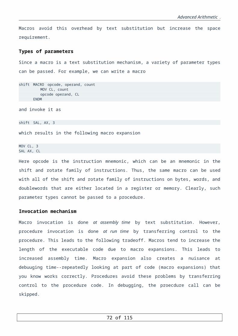
Advanced Arithmetic
Another way for indicating when a macro is invoked incorrectly is by using the .ERR directive. When the
assembler encounters this directive, it displayes the message "forced error", which indicates a fatal assembly
error.
IFIDN and IFDIF Directives
The syntax of IFIDN (if identical) and (if different) directives is
IFIDN < argument1 >, < argument2 > IFDIF < argument1 >, < argument2 >
The angle brackets are required. The condition block of statements are assembled if the arguments are identical
(IFIDN) or different (IFDIF) character strings.
These two directives are case sensitive (i.e., AX and Ax are not identical). The case insensitive versions of these
directives are IFIDNI and IFDIFI (i.e., with these directives, AX and Ax are treated as identical).
Example: Write a macro to compute the square of an unsigned byte operand and store the result in the operand itself assuming that it can fit in a byte. The operand can be a register or memory operand. SQUAREB MACRO operand IFDIFI <AL>,<operand> PUSH AX MOV AL, operand ENDIF MUL operand IFDIFI <AL>,<operand> MOV operand, AL POP AX ENDIF ENDM
The above example cannot be coded to meet the requirements of the macro without using the IFDIFI directive.
Directives Overhead
72 of 85

Advanced Arithmetic
String Handling Instructions
Objectives:
To describe Pentium string manipulation instructions
Understand the effect of Direction Flag on string instructions
Understand the role of SI and DI registers in string instructions
Learn Move String Instructions: MOVS, MOVSB, MOVSW, MOVSD
Learn Compare String Instructions: CMPS, CMPSB, CMPSW, CMPSD
Learn Scan String Instructions: SCAS, SCASB, SCASW, SCASD
Learn Store String Instructions: STOS, STOSB, STOSW, STOSD
Learn Load String Instructions: LODS, LODSB, LODSW, LODSD
Learn String Prefixes: REP, REPE, REPNE
Introduction
A string is a sequence of characters. String processing is an important aspect of any programming language.
String handling instructions allow the programmer to deal with strings in an efficient way. String instructions
operate on blocks, or contiguous linear arrays, of memory.
There are five classes of string instructions:
Move string instructions: MOVS, MOVSB, MOVSW, MOVSD. These instructions are used to copy a
block of memory to another block of memory.
Compare string instructions: CMPS, CMPSB, CMPSW, CMPSD. These instructions are used for
comparing two blocks of memory.
Scan string instructions: SCAS, SCASB, SCASW, SCASD. These instructions are used for scanning a
block of memory for a particular value.
Store string instructions: STOS, STOSB, STOSW, STOSD. These instructions are used for storing
values into a block of memory.
Load string instructions: LODS, LODSB, LODSW, LODSD. These instructions are used for loading
values from a block of memory.
All the string instructions assume the following:
The address of the source string is stored in the SI register.
The address of the destination string is stored in the DI register.
The offset stored in SI is relative to the Data Segment (DS).
The offset stored in DI is relative to the Extra Segment (ES).
73 of 85
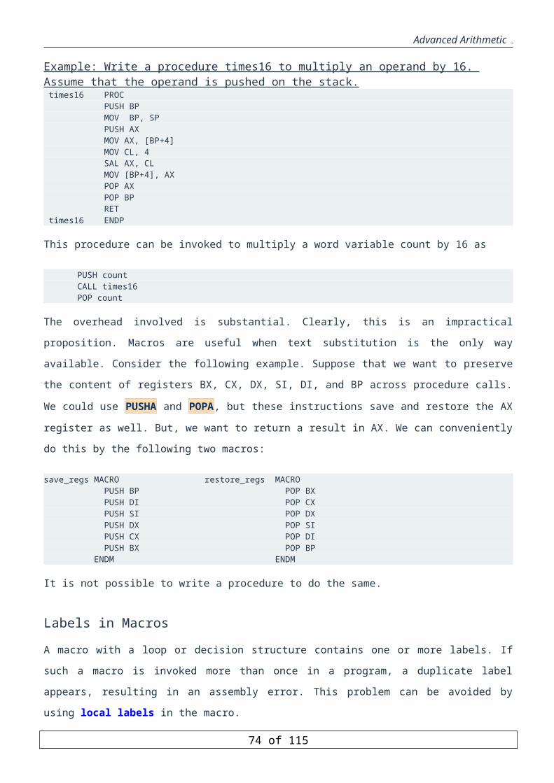
Advanced Arithmetic
All string instructions do not have explicit operands except the general forms of string instructions:
MOVS, CMPS, SCAS, STOS, LODS.
The operands used in the general forms of string instructions are just used to determine the size of the
operands.
Depending on the size of the operands:
the MOVS instruction will be replaced by MOVSB, MOVSW, or MOVSD.
the CMPS instruction will be replaced by CMPSB, CMPSW, or CMPSD.
the SCAS instruction will be replaced by SCASB, SCASW, or SCASD.
the STOS instruction will be replaced by STOSB, STOSW, or STOSD.
the LODS instruction will be replaced by LODSB, LODSW, or LODSD.
Depending on the direction flag, the SI and/or DI registers are either incremented or decremented to
point at the next address in the string.
If the Direction Flag is 0, the SI and/or DI are incremented.
If the Direction Flag is 1, the SI and/or DI are decremented.
The SI and/or DI registers are either incremented or decremented by 1, 2, or 4 depending on the
string instruction executed.
The instruction CLD clears the Direction Flag.
The instruction STD sets the Direction Flag.
Since the offset of the SI is relative to the DS and the offset of the DI is relative to the ES, we need to make ES
equal to DS if both strings are in the DS. This can be easily accomplished by the following instructions:
PUSH DSPOP ES
Move String Instructions
The move string instructions are used to copy an array from one location to another location. They have one of the
following forms:
MOVS dest_string, src_string
MOVSB
MOVSW
MOVSD
When the first form, MOVS des_string, src_string, is used the assembler will replace it by MOVSB, MOVSW, or
MOVSD depending on the size of the operands dest_string and src_string.
The semantics of the instructions MOVSB, MOVSW, and MOVSD are illustrated below:
74 of 85
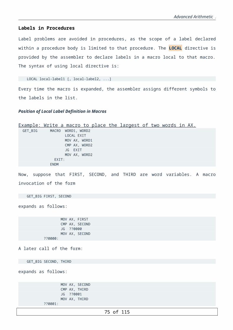
Advanced Arithmetic
Instruction Description
MOVSB
ES:[DI]<-DS[SI] ;IF (DF=0) {SI=SI+1; DI=DI+1} ELSE {SI=SI-1;DI=DI-1}
MOVSW
ES:[DI+1:DI]<-DS[SI+1:SI] ;
IF (DF=0) {SI=SI+2; DI=DI+2} ELSE {SI=SI-2;DI=DI-2}
MOVSD
ES:[DI+3:DI]<-DS[SI+3:SI] ;
IF (DF=0) {SI=SI+4; DI=DI+4} ELSE {SI=SI-4;DI=DI-4}
The MOVSB instruction
The MOVSB (move string, byte) instruction fetches the byte at address SI, stores it at address DI and then
increments or decrements the SI and DI registers by one.
The MOVSW instruction
The MOVSW (move string, word) instruction fetches the word at address SI, stores it at address DI and then
increments or decrements SI and DI by two.
The MOVSD instruction
The MOVSD (move string, double word) instruction fetches the double word at address SI, stores it at address DI
and then increments or decrements SI and DI by four.
Let us consider the case of moving (i.e. copying) an array Array1 from one location to another location Array2,
assuming the number of elements to move is 100 bytes.
If we use the normal MOV instructions, the program would look like:
Example: Copy 100 bytes from Array1 to Array2, using the MOV instruction.
LEA DI, Array2 ; Starting address of Destination LEA SI, Array1 ; Starting address of SourceMOV CX, 100 ; Number of elements = 100
Next: MOV AL, [SI] ; AL <== [SI]MOV [DI], AL ; [DI] <== ALINC SI ; SI + 1INC DI ; DI + 1LOOP Next ; Next element...
75 of 85
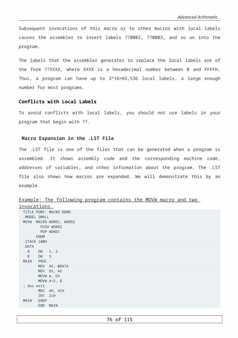
Advanced Arithmetic
However, If the string instructions are used, the code would be:
Example: Copy 100 bytes from Array1 to Array2, using MOVSB instruction.
LEA DI, Array2 ; Starting address of DestinationLEA SI, Array1 ; Starting address of SourceMOV CX, 100 ; Number of elements = 100PUSH DSPOP ES ; make ES=DSCLD ; set SI and DI to auto-increment
next: MOVSBLOOP next
REP Prefix
Since string instructions are designed to operate on arrays of bytes, words, or double words, their execution is
repeated depending on the size of the processed arrays. Instead of using the Loop instruction, the string
instructions come with a repeat prefix, REP, that allows their execution to be repeated a number of times
depending on the unsigned content of the CX register. The semantics of REP are:
While (CX <> 0)execute the string instructionCX = CX -1
end while
The CX register is first checked and if it is not 0, only then is the string instruction is executed. Thus, if CX is 0 to
start with, the string instruction is not executed at all. This is in contrast to the LOOP instruction, which first
decrements CX and then tests if CX is 0.
Next we show how the above example can be used with the REP prefix.
Example: Copy 100 bytes from Array1 to Array2, using MOVSB instruction with the REP prefix.
LEA DI, Array2 ; Starting address of Destination LEA SI, Array1 ; Starting address of Source MOV CX, 100 ; Number of elements = 100 PUSH DSPOP ES ; make ES=DSCLD ; set SI and DI to auto-increment
REP MOVSB
Note that Array1 can also be copied to Array2 using the MOVSW instruction. This is illustrated in the example
below.
Example: Copy 100 bytes from Array1 to Array2, using MOVSW instruction with the REP prefix.
LEA DI, Array2 ; Starting address of DestinationLEA SI, Array1 ; Starting address of SourceMOV CX, 50 ; Number of elements = 50 words = 100 bytes PUSH DSPOP ES ; make ES=DSCLD ;set SI and DI to auto-increment
76 of 85

Advanced Arithmetic
REP MOVSW
We can also copy Array1 into Array2 by starting the copying from the bottom of the arrays. This is called the
auto-decrement mode since SI and DI will be decremented after the move operation. This is illustrated in the
example below.
Example: Copy 100 bytes from Array1 to Array2, using MOVSB instruction with the REP prefix based on the auto-decrement mode.
LEA DI, Array2+99 ; Ending address of Destination LEA SI, Array1+99 ; Ending address of Source MOV CX, 100 ; Number of elements = 100 bytes PUSH DSPOP ES ; make ES=DSSTD ; set SI and DI to auto-decrement
REP MOVSB
In the next example, we illustrate the use of move string instructions to copy Array1 into Array2 in reverse.
Example: Copy 100 bytes from Array1 to Array2 in reverse order.
LEA DI, Array2+99 ; Ending address of Destination LEA SI, Array1 ; Starting address of SourceMOV CX, 100 ; Number of elements = 100 bytes PUSH DSPOP ES ; make ES=DSCLD ; set SI and DI to auto-increment
Next: MOVSBSUB DI, 2 ; adjust DI to pint at next addressLOOP Next
Note that in the above example, SI and DI are both incremented after the data movement. However, what we want
is to have SI incremented by one while DI is decremented by one. To achieve this, we decrement DI by 2 after the
MOVSB instruction so that the net effect on DI is decrementing it by 1. For this reason, we can not use the REP
prefix here and we have to use the loop instruction.
Compare String Instructions
The compare string instructions are used to compare two strings. They have one of the following forms:
CMPS dest_string, src_string
CMPSB
CMPSW
CMPSD
When the first form, CMPS des_string, src_string, is used the assembler will replace it by CMPSB, CMPSW, or
CMPSD depending on the size of the operands dest_string and src_string.
The semantics of the instructions CMPSB, CMPSW, and CMPSD are illustrated below:
77 of 85
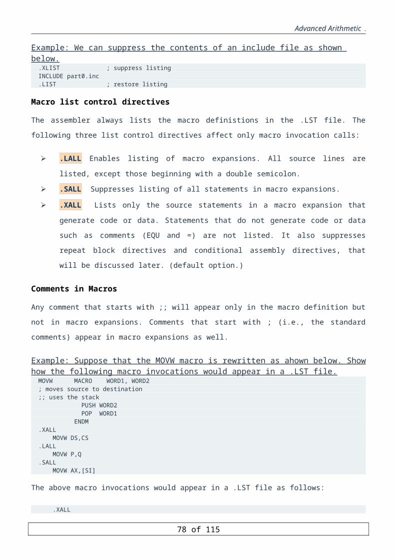
Advanced Arithmetic
Instruction Description
CMPSB
Affect the flags based on the result of DS:[SI]-ES:[DI] ;IF (DF=0) {SI=SI+1; DI=DI+1} ELSE {SI=SI-1;DI=DI-1}
CMPSW
Affect the flags based on the result of DS:[SI+1:SI]-ES:[DI+1:DI] ; IF (DF=0) {SI=SI+2; DI=DI+2} ELSE {SI=SI-2;DI=DI-2}
CMPSD
Affect the flags based on the result of DS:[SI+3:SI]-ES:[D3+1:DI] ;
IF (DF=0) {SI=SI+4; DI=DI+4} ELSE {SI=SI-4;DI=DI-4}
Note that unlike the CMP instruction which performs the operation destination - source, the compare string
instructions perform the operation source - destination.
The CMPSB Instruction
This instruction is used to compare arrays of bytes. It compares the byte addressed by DS:[SI] to the byte
addressed by ES:[DI] by performing the subtraction operation DS:[SI] - ES:[DI], setting the arithmetic flags
based on the result of the subtraction. Note that the result is not stored and is just used to affect the flags. Then, SI
and DI are either incremented or decremented by 1 depending on the Direction Flag. After executing this
instruction, it is possible to use any of the conditional jump instructions.
The CMPSW Instruction
This instruction is used to compare arrays of words. It compares the word addressed by DS:[SI] to the word
addressed by ES:[DI] by performing the subtraction operation DS:[SI+1:SI] - ES:[DI+1:DI], setting the arithmetic
flags based on the result of the subtraction. Then, SI and DI are either incremented or decremented by 2
depending on the Direction Flag.
The CMPSD Instruction
This instruction is used to compare arrays of double words. It compares the double word addressed by DS:[SI] to
the double word addressed by ES:[DI] by performing the subtraction operation DS:[SI+3:SI] - ES:[DI+3:DI],
setting the arithmetic flags based on the result of the subtraction. Then, SI and DI are either incremented or
decremented by 4 depending on the Direction Flag.
In the next example, we illustrate the use of compare string instructions in comparing two strings.
78 of 85

Advanced Arithmetic
Example: Comparison of two strings.
MOV SI, offset str1MOV DI, offset str2PUSH DSPOP ESCLD ;left to right or auto-increment mode MOV CX, 12 ;string length
Next: CMPSB ;cmp till equal or cx=0JB str1smallerJA str2smaller;the strings are equal - so farLOOP Next...
REPE/REPZ Prefix
Like the unconditional repeat prefix, there are conditional repeat prefixes that come with string instructions.
REPE (Repeat if Equal) or REPZ (Repeat if ZF=1) is one of the conditional repeat prefixes that come with string
instructions. Its operation is similar to the REP prefix except that repetition is also conditional on the Zero Flag as
shown below:
While (CX <> 0)execute the string instructionCX = CX - 1;If (ZF = 0) then
exit loopend if
end while
The string instruction will repeat execution as long as CX is not equal to 0 and also the result of comparison sets
the ZF to 1, i.e. the two compared operands are equal. So, it will stop once the first mismatch is found or if CX
becomes 0.
In the next example, we show the use of the REPE prefix in comparing two strings.
Example: Comparison of two strings using REPE prefix.
MOV SI, offset str1MOV DI, offset str2PUSH DSPOP ESCLD ;left to right or auto-increment mode MOV CX, 12 ;string length
REPE CMPSB ;cmp till equal or cx=0JB str1smallerJA str2smaller;the strings are equal - so far...
REPNE/REPNZ Prefix
REPNE (Repeat if not Equal) or REPNZ (Repeat if ZF=0) is the second conditional repeat prefix. Its operation is
as follows:
79 of 85
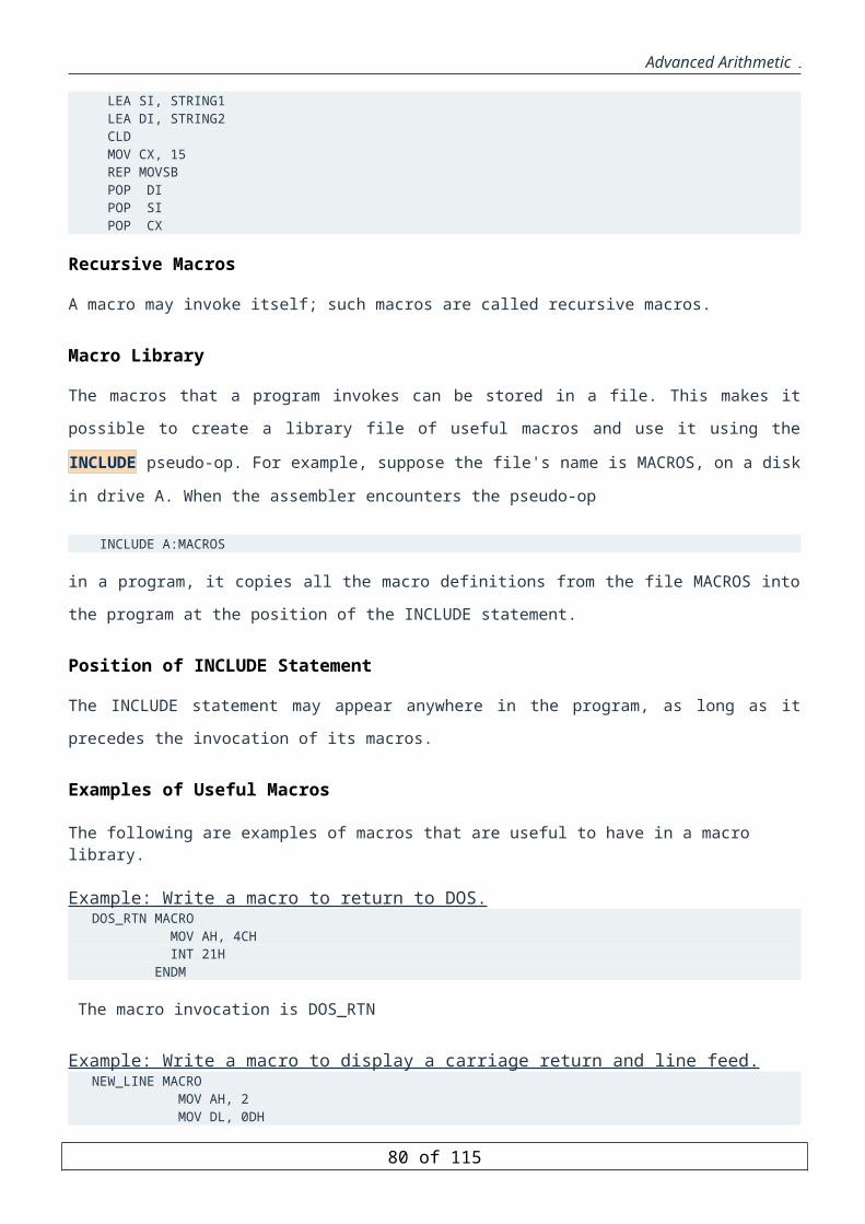
Advanced Arithmetic
While (CX <> 0)execute the string instructionCX = CX - 1;If (ZF = 1) then
exit loopend if
end while
The string instruction will repeat execution as long as CX is not equal to 0 and also the result of comparison sets
the ZF to 0, i.e. the two compared operands are not equal. So, it will stop once the first match is found or if CX
becomes 0.
For example, suppose that we want to count the number of characters that are matching between two strings. This
can be done as follows:
Example: Counting number of character matches between two strings.
MOV SI, offset str1MOV DI, offset str2PUSH DSPOP ESCLD ;left to right or auto-increment mode MOV CX, 12 ;string lengthXOR AL, AL ;# of character matches
Again: JCXZ DoneREPNE CMPSB ;cmp till equal or cx=0
JNE DoneINC ALJMP Again
Done:...
Note that it is not allowed to use the REP prefix with the compare string instructions as it does not make sense.
Similarly, it is not allowed to use the REPE/REPZ or REPNE/REPNZ prefixes with the move string instructions.
Scan String Instructions
The scan string instructions are useful in searching for a particular value or a character in a string. They have one
of the following forms:
SCAS dest_string
SCASB
SCASW
SCASD
The SCAS instruction only requires a destination string (pointed at by ES:DI) rather than both a source and a
destination string. The source operand is the value in the AL (SCASB), AX (SCASW), or EAX (SCASD)
register. The SCAS instruction compares the value in the accumulator (AL, AX, or EAX) against the value
pointed at by ES:DI and then increments (or decrements) DI by one, two, or four.
80 of 85
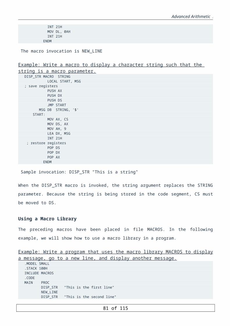
Advanced Arithmetic
When the first form, SCAS des_string, is used the assembler will replace it by SCASB, SCASW, or SCASD
depending on the size of the operand dest_string.
The semantics of the instructions SCASB, SCASW, and SCASD are illustrated below:
Instruction Description
SCASB
Affect the flags based on the result of AL-ES:[DI] ;IF (DF=0) DI=DI+1 ELSE DI=DI-1
SCASW
Affect the flags based on the result of AX-ES:[DI+1:DI] ; IF (DF=0) DI=DI+2 ELSE DI=DI-2
SCASD
Affect the flags based on the result of EAX-ES:[DI+3:DI] ;
IF (DF=0) DI=DI+4 ELSE DI=DI-4
The SCASB Instruction
The SCASB instruction compares the content of the AL register to the byte addressed by ES:[DI] by performing
the subtraction operation AL - ES:[DI], setting the arithmetic flags based on the result of the subtraction. Then, DI
is either incremented or decremented by 1 depending on the Direction Flag. After executing this instruction, it is
possible to use any of the conditional jump instructions.
The SCASW Instruction
The SCASW instruction compares the content of the AX register to the word addressed by ES:[DI] by performing
the subtraction operation AX - ES:[DI+1:DI], setting the arithmetic flags based on the result of the subtraction.
Then, DI is either incremented or decremented by 2 depending on the Direction Flag.
The SCASD Instruction
The SCASD instruction compares the content of the EAX register to the double word addressed by ES:[DI] by
performing the subtraction operation EAX - ES:[DI+3:DI], setting the arithmetic flags based on the result of the
subtraction. Then, DI is either incremented or decremented by 4 depending on the Direction Flag.
Similar to the compare string instructions, the conditional repeat prefixes REPE/REPZ and REPNE/REPNZ can
be used with the scan string instructions.
The next example illustrates the use of the scan string instructions in searching for a particular character in a
string.
81 of 85
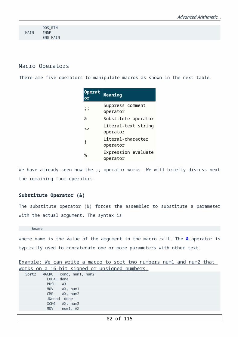
Advanced Arithmetic
Example: Character search in a string.
MOV DI, offset strPUSH DSPOP ESCLD ;left to right or auto-increment mode MOV CX, 12 ;string lengthMOV AL, 'A' ;character to be searched is A
REPNE SCASB ;cmp till equal or cx=0JNE Not_FoundDEC DI...
Note that in the above example, if the searched character is found, then DI will be pointing at the address of the
first location it is found at.
The following example can be used to skip initial blank characters in a string. It leaves DI pointing to the first
non-blank character in the searched string.
Example: Skip blank characters in a string.
MOV DI, offset strPUSH DSPOP ESCLD ;left to right or auto-increment mode MOV CX, 12 ;string lengthMOV AL, ' ' ;character to be skipped is blank
REPE SCASB ;cmp till not equal or cx=0JE No_BlankDEC DI...
Store String Instructions
The store string instructions are useful in initializing a block of memory with a particular value. They have one of
the following forms:
STOS dest_string
STOSB
STOSW
STOSD
The STOS instruction only requires a destination string (pointed at by ES:DI). The source operand is the value in
the AL (STOS), AX (STOSW), or EAX (STOSD) register. The STOS instruction stores the value in the
accumulator (AL, AX, or EAX) into the corresponding locations pointed by ES:DI and then increments (or
decrements) DI by one, two, or four.
When the first form, STOS des_string, is used the assembler will replace it by STOSB, STOSW, or STOSD
depending on the size of the operand dest_string.
82 of 85

Advanced Arithmetic
The semantics of the instructions STOSB, STOSW, and STOSD are illustrated below:
Instruction Description
STOSB
ES:[DI]<-AL ;IF (DF=0) DI=DI+1 ELSE DI=DI-1
STOSW
ES:[DI+1:DI]<-AX ; IF (DF=0) DI=DI+2 ELSE DI=DI-2
STOSD
ES:[DI+3:DI]<-EAX ;
IF (DF=0) DI=DI+4 ELSE DI=DI-4
The STOSB instruction
The STOSB stores the value in the AL register into the byte addressed by ES:[DI]. DI is then incremented (if
DF=0) or decremented (if DF=1) by 1.
The STOSW instruction
The STOSW instruction stores the AX register into the word addressed by ES:[DI]. DI is then incremented (if
DF=0) or decremented (if DF=1) by 2.
The STOSD instruction
The STOSD instruction stores the EAX register into the double word addressed by ES:[DI]. DI is then
incremented (if DF=0) or decremented (if DF=1) by 4.
Note that it is possible to use only the unconditional repeat prefix REP with store string instructions.
The next example illustrates the use of the store string instructions in initializing a block of memory by a
particular value.
Example: Initialize an array of 100 bytes by the value -1.
MOV DI, offset ArrayMOV CX, 100MOV AX, DSMOV ES, AXCLDMOV AL, -1
83 of 85

Advanced Arithmetic
REP STOSB...
Note that we can initialize the Array using the dup operator by using the following declaration in the data
segment:
Array DB 100 DUP(-1)
However, in many programming instances it is required to initialize an array repeatedly and in this case the store
string instructions can be used.
Load String Instructions
The load string instructions are useful when it is required to process the elements of an array. They have one of
the following forms:
LODS src_string
LODSB
LODSW
LODSD
The LODS instruction only requires a source string (pointed at by DS:SI). The destination operand is the AL
(LODSB), AX (LODSW), or EAX (LODSD) register. The LODS instruction loads the value from the
corresponding locations pointed by DS:SI into the accumulator (AL, AX, or EAX) and then increments (or
decrements) SI by one, two, or four.
When the first form, LODS src_string, is used the assembler will replace it by LODSB, LODSW, or LODSD
depending on the size of the operand src_string.
The semantics of the instructions LODSB, LODSW, and LODSD is illustrated below:
Instruction Description
LODSB
AL<-DS:[SI] ;IF (DF=0) SI=SI+1 ELSE SI=SI-1
LODSW
AX<-DS:[SI+1:SI] ;IF (DF=0) SI=SI+2 ELSE SI=SI-2
LODSD EAX<-DS:[SI+3:SI] ;IF (DF=0) SI=SI+4 ELSE
84 of 85

Advanced Arithmetic
SI=SI-4
The LODSB instruction
The LODSB loads the byte addressed by DS:[SI] into register AL. SI is then incremented (if DF=0) or
decremented (if DF=1) by 1.
The LODSW instruction
The LODSW loads the word addressed by DS:[SI] into register AX. SI is then incremented (if DF=0) or
decremented (if DF=1) by 2.
The LODSD instruction
The LODSD loads the double word addressed by DS:[SI] into register EAX. SI is then incremented (if DF=0) or
decremented (if DF=1) by 4.
Note that repeat prefixes cannot be used with load string instructions as their use does not make sense.
The next example illustrates the use of the load and store string instructions in converting the characters of strings
to upper case characters.
Example: Convert all string characters to upper case using load and store string instructions.
MOV SI, offset ArrayMOV DI, SIMOV CX, 100 ; Array lengthMOV AX, DSMOV ES, AXCLD
Next: LODSBOR AL, 20H ; convert to upper case
STOSBLOOP Next
Note that since the character is already an upper case, it will remain upper case by the instruction OR AL, 20H.
However, the lower case characters will be converted to upper case characters. Also, note that since the blank
character has the ASCII code 20H, it will not be affected and will remain as is.
85 of 85