city of waxahachie, texas
TRANSCRIPT
CITY OF WAXAHACHIE, TEXAS
MANUAL
FOR THE DESIGN OF
WATER AND SANITARY SEWER LINES
MAY , 2001
j:\inactive\wax\1999-151 design manuals\manuals\w & ww\index.doc
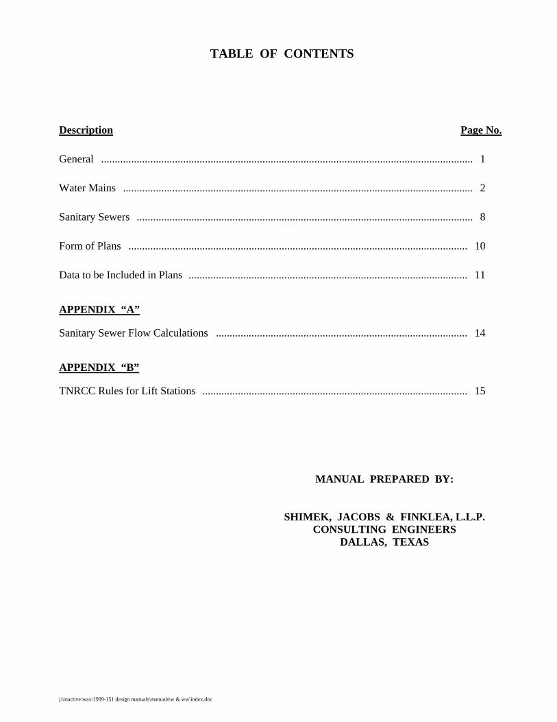
TABLE OF CONTENTS Description Page No.
General ........................................................................................................................................ 1
Water Mains ................................................................................................................................ 2
Sanitary Sewers ........................................................................................................................... 8
Form of Plans ............................................................................................................................ 10
Data to be Included in Plans ...................................................................................................... 11
APPENDIX “A”
Sanitary Sewer Flow Calculations ............................................................................................ 14
APPENDIX “B”
TNRCC Rules for Lift Stations ................................................................................................. 15
MANUAL PREPARED BY:
SHIMEK, JACOBS & FINKLEA, L.L.P. CONSULTING ENGINEERS
DALLAS, TEXAS
Water & Sanitary Sewer Lines Manual j:\inactive\wax\1999-151 design manuals\manuals\w & ww\manual.doc - 1 -
CITY OF WAXAHACHIE, TEXAS
MANUAL FOR THE DESIGN OF WATER AND SANITARY SEWER LINES
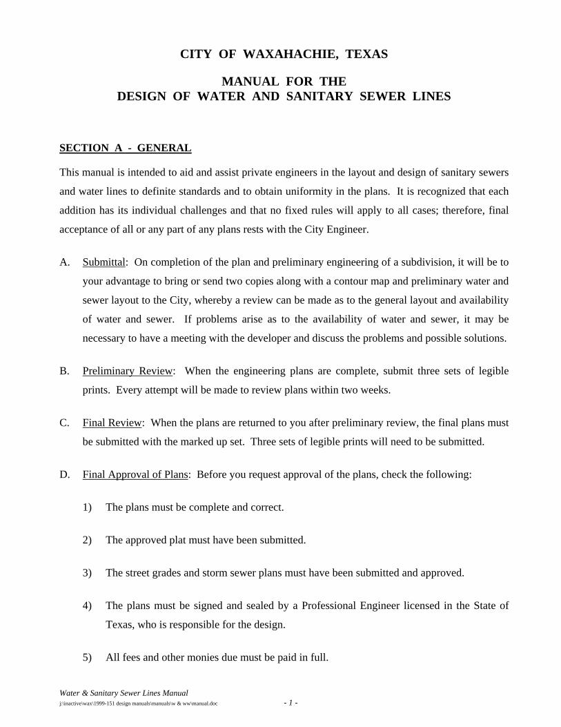
SECTION A - GENERAL
This manual is intended to aid and assist private engineers in the layout and design of sanitary sewers
and water lines to definite standards and to obtain uniformity in the plans. It is recognized that each
addition has its individual challenges and that no fixed rules will apply to all cases; therefore, final
acceptance of all or any part of any plans rests with the City Engineer.
A. Submittal: On completion of the plan and preliminary engineering of a subdivision, it will be to
your advantage to bring or send two copies along with a contour map and preliminary water and
sewer layout to the City, whereby a review can be made as to the general layout and availability
of water and sewer. If problems arise as to the availability of water and sewer, it may be
necessary to have a meeting with the developer and discuss the problems and possible solutions.
B. Preliminary Review: When the engineering plans are complete, submit three sets of legible
prints. Every attempt will be made to review plans within two weeks.
C. Final Review: When the plans are returned to you after preliminary review, the final plans must
be submitted with the marked up set. Three sets of legible prints will need to be submitted.
D. Final Approval of Plans: Before you request approval of the plans, check the following:
1) The plans must be complete and correct.
2) The approved plat must have been submitted.
3) The street grades and storm sewer plans must have been submitted and approved.
4) The plans must be signed and sealed by a Professional Engineer licensed in the State of
Texas, who is responsible for the design.
5) All fees and other monies due must be paid in full.
Water & Sanitary Sewer Lines Manual j:\inactive\wax\1999-151 design manuals\manuals\w & ww\manual.doc - 2 -
6) Contractor's insurance must be in correct form.
7) Three sets of complete engineering plans are required for City use. There should be
additional approved plans available for Contractors and Engineering Consultants use
during construction of the improvements. Only those plans with the "approved" stamp will
be recognized by the City Representative.
8) Upon completion of construction and prior to acceptance of that construction by the City,
one set of mylars and one set of prints of the record drawings must be submitted to the
City.
E. Specifications are the Standard Specifications for Public Work Construction, North Central
Texas latest addition as prepared by the North Central Texas Council of Governments.
F. Special Provisions are City of Waxahachie Special Provisions to the Specifications.
G. Standard Details are as prepared by the North Central Texas Council of Governments.
SECTION B - WATER MAINS
In general, water mains are placed on the north and west sides of a street, at a distance of ten feet
from the centerline of the street, or otherwise as directed by the City Engineer. Where applicable,
line sizes will comply with the Water Distribution System Master Plan and be adequate to convey a
fire flow. Fire flow analysis will be required on lines that are questionable. Starting pressures shall
be obtained from the nearest junction node as stated in the City’s Water Distribution Master Plan
computer printouts.
A. Minimum 8-inch pipe required in residential areas.
B. Minimum 12-inch pipe required on commercial, retail and industrial areas.
C. Dead-end mains shall not exceed 600 feet in length, a water meter service in a lockable meter
box will be required at the end of the main.
D. No water main shall be located closer than 5-feet from any tree or structure.
Water & Sanitary Sewer Lines Manual j:\inactive\wax\1999-151 design manuals\manuals\w & ww\manual.doc - 3 -
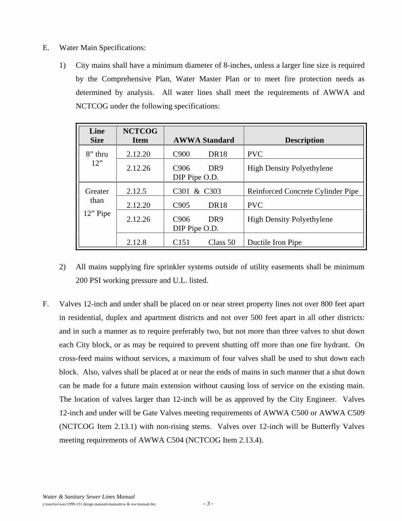
E. Water Main Specifications:
1) City mains shall have a minimum diameter of 8-inches, unless a larger line size is required
by the Comprehensive Plan, Water Master Plan or to meet fire protection needs as
determined by analysis. All water lines shall meet the requirements of AWWA and
NCTCOG under the following specifications:
Line Size
NCTCOG Item
AWWA Standard
Description
8” thru 12”
2.12.20 C900 DR18 PVC
2.12.26 C906 DR9 DIP Pipe O.D.
High Density Polyethylene
Greater than
12” Pipe
2.12.5 C301 & C303 Reinforced Concrete Cylinder Pipe
2.12.20 C905 DR18 PVC
2.12.26 C906 DR9 DIP Pipe O.D.
High Density Polyethylene
2.12.8 C151 Class 50 Ductile Iron Pipe
2) All mains supplying fire sprinkler systems outside of utility easements shall be minimum
200 PSI working pressure and U.L. listed.
F. Valves 12-inch and under shall be placed on or near street property lines not over 800 feet apart
in residential, duplex and apartment districts and not over 500 feet apart in all other districts:
and in such a manner as to require preferably two, but not more than three valves to shut down
each City block, or as may be required to prevent shutting off more than one fire hydrant. On
cross-feed mains without services, a maximum of four valves shall be used to shut down each
block. Also, valves shall be placed at or near the ends of mains in such manner that a shut down
can be made for a future main extension without causing loss of service on the existing main.
The location of valves larger than 12-inch will be as approved by the City Engineer. Valves
12-inch and under will be Gate Valves meeting requirements of AWWA C500 or AWWA C509
(NCTCOG Item 2.13.1) with non-rising stems. Valves over 12-inch will be Butterfly Valves
meeting requirements of AWWA C504 (NCTCOG Item 2.13.4).
Water & Sanitary Sewer Lines Manual j:\inactive\wax\1999-151 design manuals\manuals\w & ww\manual.doc - 4 -
G. Fire Hydrants
Section 1. Number and Locations
A sufficient number of fire hydrants shall be installed to provide hose stream protection for every point on the exterior wall of the building with the lengths of hose normally attached to the hydrants. There shall be sufficient hydrants to concentrate the required fire flow, as recommended by the publication "GUIDE FOR DETERMINATION OF REQUIRED FIRE FLOW" published by the Insurance Service Office, around any building with no hose line exceeding the distances hereinafter established and with an adequate flow available from the water system to meet this required flow. In addition, the following guidelines shall be met or exceeded:
1) SINGLE FAMILY AND DUPLEX RESIDENTIAL - As the property is developed, fire hydrants shall be located at all intersecting streets and at intermediate locations between intersections at a maximum spacing of 500 feet between fire hydrants as measured along the route that fire hose is laid by a fire vehicle.
2) MULTIFAMILY RESIDENTIAL - As the property is developed, fire hydrants shall be located at all intersecting streets and at intermediate locations between intersections at a maximum spacing of 400 feet as measured along the length of the centerline of the roadway, and the front of any structure at grade shall be no further than 500 feet from a minimum of two fire hydrants as measured along the route that a fire hose is laid by a fire vehicle.
3) OTHER DISTRICTS - As the property is developed, fire hydrants shall be located at all intersecting streets and at intermediate locations between intersections at a maximum spacing of 300 feet as measured along the length of the centerline of the roadway, and the front of any building at grade shall be no farther than 300 feet from a minimum of two fire hydrants as measured along the route that the fire hose is laid by a fire vehicle.
4) PROTECTED PROPERTIES - Fire hydrants required to provide a supplemental water supply for automatic fire protection systems shall be within 100 feet of the Fire Department connection for such system.
5) BUILDINGS FIRE SPRINKLED - An 8-inch fire line stub-out with valve shall be provided for all buildings to be sprinkled. A smaller stub-out can only be used with Fire Department approval.
Water & Sanitary Sewer Lines Manual j:\inactive\wax\1999-151 design manuals\manuals\w & ww\manual.doc - 5 -
6) Fire hydrants shall be installed along all fire lane areas as follows:
a) Non-Residential Property or Use
• Within 150 feet of the main entrance.
• Within 100 feet of any Fire Department connection.
• At a maximum intermediate spacing of 300 feet as measured along the length of the fire lane.
b) Apartment. Townhouse' or Cluster Residential Property or Use
• Within 100 feet of any Fire Department connection.
• At maximum intermediate spacing of 400 feet as measured along the length of the fire lane.
7) Generally, no fire hydrant shall be located closer than 50-feet to a non-residential building or structure unless approved by the Engineering and Fire Departments.
8) In instances where access between the fire hydrant and the building that it is intended to serve may be blocked, extra fire hydrants shall be provided to improve the fire protection. Railroads, divided thoroughfares, expressways, blocks which are subject to buildings restricting movement, and other man-made or natural obstacles are considered as barriers.
Section 2. Restrictions
1) All required fire hydrants shall be of the national standard 3-way breakaway type no less than 5¼-inches in size and shall conform to the provisions of the latest AWWA Standard C502 and shall be placed upon water mains of no less than 8-inches in size. Fire hydrants shall have a bury depth of five feet.
2) Valves shall be placed on all fire hydrants leads. Valves shall be flanged by mechanical joint.
3) Required fire hydrants shall be installed so the breakaway point will be no less than 2-inches, and no greater than 6-inches above the grade surface.
4) Fire hydrants shall be located a minimum of 2-feet and a maximum of 6-feet behind the curb line, based on the location of the sidewalk. The fire hydrant shall not be in the sidewalk.
Water & Sanitary Sewer Lines Manual j:\inactive\wax\1999-151 design manuals\manuals\w & ww\manual.doc - 6 -
5) All required public fire hydrants placed on private property shall be adequately protected
by either curb stops or concrete posts or other methods as approved by the City Engineer
and Fire Chief and shall be in easements. Such stops or posts to be the responsibility of the
landowner on which the said fire hydrant is placed.
6) All required fire hydrants shall be installed so that the steamer connection will face the fire
lane or street, or as directed by the Fire Department.
7) Fire hydrants, when placed at intersections or access drives to parking lots, when practical,
shall be placed so that no part of the fire truck will block the intersection or parking lot
access when connections to the fire hydrant are made.
8) Fire hydrants, required by this article, and located on either public or private property, shall
be accessible to the Fire Department at all times.
9) Fire hydrants shall be located at street or fire lane intersections, when feasible.
10) A Blue Stimsonite, Fire-Lite reflector (or approved equal) shall be placed in the center of
the drive lane on the side of the fire hydrants.
11) In non-residential developments an 8-inch lead will be required on all fire hydrants that are
located more than 50-feet from the looped main.
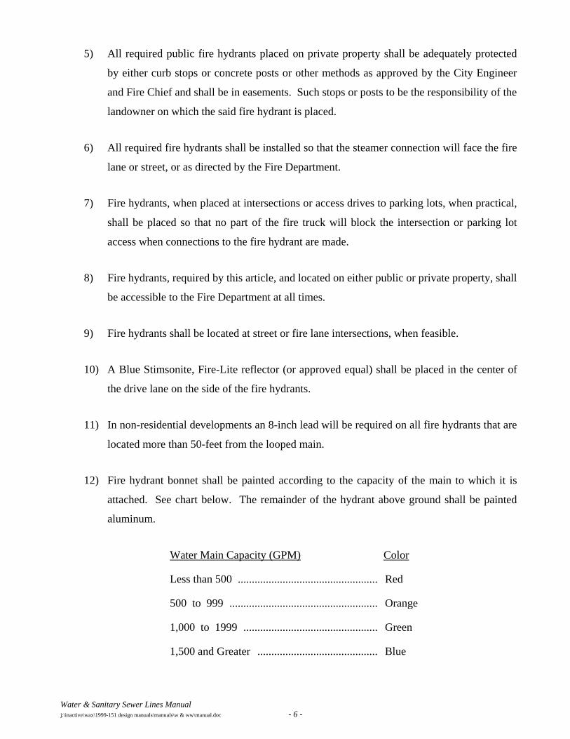
12) Fire hydrant bonnet shall be painted according to the capacity of the main to which it is
attached. See chart below. The remainder of the hydrant above ground shall be painted
aluminum.
Water Main Capacity (GPM) Color
Less than 500 .................................................. Red
500 to 999 ..................................................... Orange
1,000 to 1999 ................................................ Green
1,500 and Greater ........................................... Blue
Water & Sanitary Sewer Lines Manual j:\inactive\wax\1999-151 design manuals\manuals\w & ww\manual.doc - 7 -
H. Four-inch mains used for hydrant supply shall be replaced and dead-ends eliminated where
practical. Six-inch lines shall be connected so that not more than one hydrant will be between
intersecting lines and not more than two hydrants on an eight-inch main between intersecting
lines.
I. The minimum cover to the top of the pipe must vary with the valve stem. In general, the
minimum cover below the top of the street subgrade should be as follows: 6-inch and smaller,
3.5 feet; 8-inch, 4.0 feet: 12-inch, 4.5 feet to 5 feet; 16-inch, 5.0 feet to 5.5 feet. Lines larger
than 16-inch shall have a minimum of 6 feet of cover, which is sufficient to allow water and
sewer and other utilities to go over the large main. For water lines to be constructed along
county-type roads commonly built with a high crown about the surrounding property, increase
the cover as required to allow for future paving grade changes.
J. A service with a meter box is constructed from the main to a point just behind the curb line,
usually in advance of paving. The location of the meter box will either be at or near the center
of the front of the lot or at every other property line. The type of development will determine
this location. On multiple apartments and business properties, the desired size and location is
usually specified by the Owner or Architect. Minimum requirements for water service sizes are:
1) One-inch copper services are required to serve all residential lots including townhouse lots
and patio homes. Separate services shall be provided for each of the family units.
2) The size of apartment, condominium, or multi-family services will depend on the number
of units served with a minimum of one meter per building.
3) Fittings shall include megalugs on 3” and larger services.
K. A domestic service connection shall not be allowed on fire hydrant leads.
Water & Sanitary Sewer Lines Manual j:\inactive\wax\1999-151 design manuals\manuals\w & ww\manual.doc - 8 -
SECTION C - SANITARY SEWERS
A. Sizes and grades for sanitary sewer lines shall be based on serving the proposed development
and all upstream areas in the drainage basin at full development. Design calculations for sizing
lines shall be included in the plans, along with drainage area map. If feasible, sewers shall be
placed in streets. Sewers are usually located in the center of the street. Each addition has its
challenges, therefore, no fixed rules will apply to all cases.
B. Minimum cover shall be 3.5 feet; exceptions authorized by the City Engineer shall have
concrete protection. In general, the minimum depth for sewer to serve given property with a
4-inch lateral shall be 3-feet plus 0.02 times the length of the house lateral (the distance from the
sewer to the center of the house). Thus, for a house 135 feet from the sewer, the depth would be
3-feet plus 0.02 x 135 feet = 3.0 plus 2.7 = 5.7 feet. The depth of the flow line of the sewer
should then be at least 5.7 feet below the elevation of the ground at the point where the service
enters the house. Profiles of the ground line 20-feet past the building line will be required to
verify that this criteria is met. On lines deeper than 12 feet, a parallel sewer line will be required
when laterals are to be attached. This requirement should be discussed with the City Engineer.
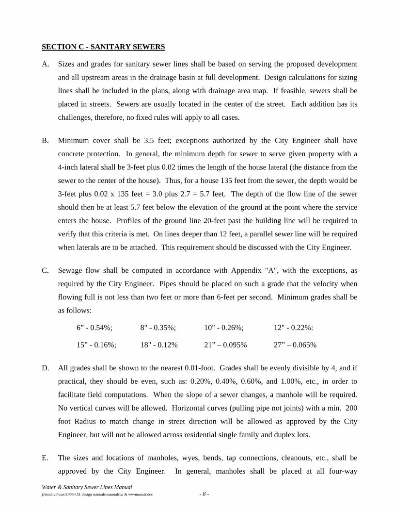
C. Sewage flow shall be computed in accordance with Appendix "A", with the exceptions, as
required by the City Engineer. Pipes should be placed on such a grade that the velocity when
flowing full is not less than two feet or more than 6-feet per second. Minimum grades shall be
as follows:
6” - 0.54%; 8" - 0.35%; 10" - 0.26%; 12" - 0.22%:
15” - 0.16%; 18" - 0.12% 21” – 0.095% 27” – 0.065%
D. All grades shall be shown to the nearest 0.01-foot. Grades shall be evenly divisible by 4, and if
practical, they should be even, such as: 0.20%, 0.40%, 0.60%, and 1.00%, etc., in order to
facilitate field computations. When the slope of a sewer changes, a manhole will be required.
No vertical curves will be allowed. Horizontal curves (pulling pipe not joints) with a min. 200
foot Radius to match change in street direction will be allowed as approved by the City
Engineer, but will not be allowed across residential single family and duplex lots.
E. The sizes and locations of manholes, wyes, bends, tap connections, cleanouts, etc., shall be
approved by the City Engineer. In general, manholes shall be placed at all four-way
Water & Sanitary Sewer Lines Manual j:\inactive\wax\1999-151 design manuals\manuals\w & ww\manual.doc - 9 -
connections and three-way connections. The diameter of a manhole constructed over the center
of a sewer should vary with the size of the sewer. For 6", 8", and 10" sewers, the manhole shall
be 4.0-foot minimum diameter; for 12", 15", 18", 21", 24" and 27" - 5.0 foot minimum
diameter; 30" and 36" - 6-foot minimum diameter. In Flood Plains, sealed manholes are to be
used to prevent the entrance of storm water. Manholes in flood plains shall be vented as
required by TNRCC. Clean-outs shall be placed on the ends of all lines. Drop manholes shall
be required when the inflow elevation is more than 18-inches above the outflow elevation.
Construct manholes at each end of lines that are installed by other than open cut and at each end
of aerial crossing lines. Sewer mains and water mains shall be not less than nine feet apart, edge
to edge of pipe.
F. LATERALS: The sizes and locations of laterals shall be as approved by the City Engineer. In
general, for single family dwellings, the lateral size shall be 4" minimum; for multiple units,
apartments, local retail and commercial - 6" minimum; for manufacturing and industrial, the
size should be 8" or larger as required. House laterals usually come out 10 feet downstream
from the center of the lot and shall have a 10-foot lateral separation from the water service.
Manholes will be required on 6-inch and larger laterals where they connect to the main line.
Laterals will not be attached to sewer mains that are deeper than 12 feet. A minimum of one
lateral per building shall be required. Also, a minimum of one lateral per residential lot shall be
required. Duplexes shall have two laterals.
G. Railroad, State Highway and creek crossings, etc., shall be as approved by the City Engineer.
The developer is responsible for obtaining permits from the Railroad Company and from the
Texas Department of Highways & Public Transportation.
H. Line and grade stakes for construction shall be furnished by the developer's Engineer. All
property lines and corners must be properly staked to insure correct alignment. The City will
not be liable for improper alignment or delay of any kind caused by improper or inadequate
surveys by the developer or by interference of other utilities.
I. In order to provide access for sewer lines for cleaning, manholes and/or cleanouts shall be so
located that 250 feet of sewer cleaning equipment can reach any point in the line. This means
that manhole spacing shall be a maximum of 500 feet: that spacing between a manhole and an
upstream cleanout shall be limited to 400 feet. Cleanouts may be located at the end of the line
only.
Water & Sanitary Sewer Lines Manual j:\inactive\wax\1999-151 design manuals\manuals\w & ww\manual.doc - 10 -
J. No sewer line shall be located nearer than five feet from any tree or structure.
K. No sanitary sewer in alleys unless approved by the City Engineer.
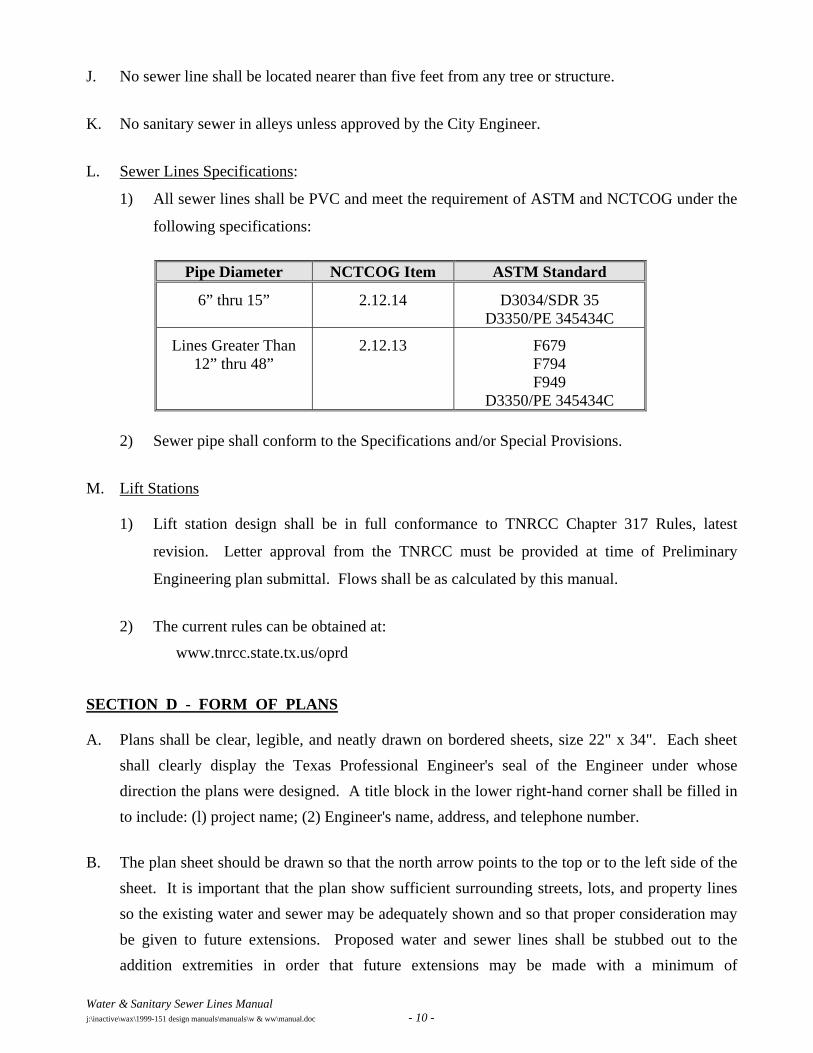
L. Sewer Lines Specifications:
1) All sewer lines shall be PVC and meet the requirement of ASTM and NCTCOG under the
following specifications:
Pipe Diameter NCTCOG Item ASTM Standard
6” thru 15” 2.12.14 D3034/SDR 35 D3350/PE 345434C
Lines Greater Than 12” thru 48”
2.12.13 F679 F794 F949
D3350/PE 345434C
2) Sewer pipe shall conform to the Specifications and/or Special Provisions.
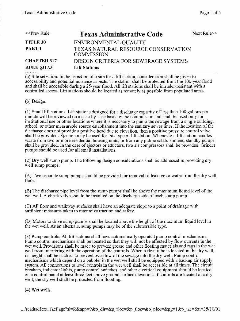
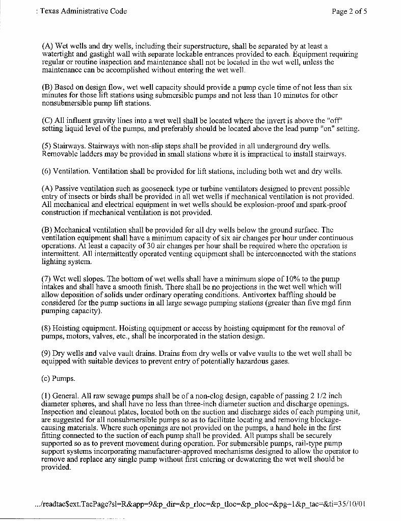
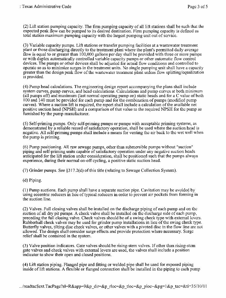
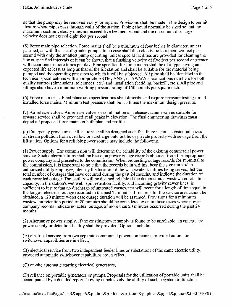
M. Lift Stations
1) Lift station design shall be in full conformance to TNRCC Chapter 317 Rules, latest
revision. Letter approval from the TNRCC must be provided at time of Preliminary
Engineering plan submittal. Flows shall be as calculated by this manual.
2) The current rules can be obtained at:
www.tnrcc.state.tx.us/oprd
SECTION D - FORM OF PLANS
A. Plans shall be clear, legible, and neatly drawn on bordered sheets, size 22" x 34". Each sheet shall clearly display the Texas Professional Engineer's seal of the Engineer under whose direction the plans were designed. A title block in the lower right-hand corner shall be filled in to include: (l) project name; (2) Engineer's name, address, and telephone number.
B. The plan sheet should be drawn so that the north arrow points to the top or to the left side of the sheet. It is important that the plan show sufficient surrounding streets, lots, and property lines so the existing water and sewer may be adequately shown and so that proper consideration may be given to future extensions. Proposed water and sewer lines shall be stubbed out to the addition extremities in order that future extensions may be made with a minimum of
Water & Sanitary Sewer Lines Manual j:\inactive\wax\1999-151 design manuals\manuals\w & ww\manual.doc - 11 -
inconvenience. Unless it would make the plan very difficult to read, both water and sewer lines should be shown on the same sheet. The lines on the profile sheet shall be drawn in the same direction as on the plan. Lettering shall be oriented to be read upward or to the left.
C. On large additions or layouts requiring the use of more than six sheets (total of plan & profile), key sheets may be required on a scale of 1" = 400' or 1" = 1000', as designated by the City Engineer. They shall show the overall layout with the specific project clearly indicated with reference to individual sheets.
D. The use of "off-standard" scales will not be permitted. A plan shall be drawn to scales of 1" = 20', or 1" = 40'. Plans for water and sewer that do not involve great detail should be drawn on a scale of 1" = 50'. Plans in and along creeks, heavily wooded sections, streets with numerous utilities, or as may be required to produce a clean and legible drawing, shall be drawn on plan-profile sheets or separate plan and profile sheets on a scale 1" = 40'. If the plan is in an extremely congested area, a scale of 1" = 20' may be necessary. All profiles shall be drawn on a vertical scale (1” = 4’) as required for clarity, and the horizontal scale shall be the same as for the plan unless otherwise directed by the City Engineer.
SECTION E - DATA TO BE INCLUDED IN PLANS
A. Sewer Data to be Included on Plan Sheet: The plan shall show the existing and proposed water and sewer lines and all appurtenances thereto. The plan should also have the storm sewer system dashed in. All lines shall be numbered, lettered or otherwise designated on both plan and profile sheets. All lines shall show sizes and direction of flow on both plan and profile sheets. Stationing shall be shown to the nearest 0.1 foot and each new line shall begin at 0+00 at the outlet and increase up the sewer. Station pluses at all junctions of sewers, horizontal P.C.'s, and P.T.'s, bends, angle points, wyes, cleanouts, manholes, the centerlines of all cross streets and railroads, and all crossing utilities, etc., shall be shown on both plan and profile. The degree of angles and horizontal curve data shall be shown on the plan only. Minimum Radius for sanitary sewer mains is 200 feet by pulling pipe not joints. Sewer laterals shall be shown at a location most convenient to serve the property.
Sewer laterals will usually be near the center of the lot, either at the street or alley. If the lateral is to be adjacent to the water service, then show the lateral 10 feet downstream. The location shall be designated on the plans.
Water & Sanitary Sewer Lines Manual j:\inactive\wax\1999-151 design manuals\manuals\w & ww\manual.doc - 12 -
B. Sewer Data to be Included on the Profile Sheet: The data for the profile sheet shall be obtained by running a line of levels along the actual route and by taking any other necessary observations. Profiles shall show the elevations to the nearest 0.1 foot of the ground at the centerline of the sewer, and to the right and left of the centerline of the sewer at the location of the approximate center of the proposed houses or buildings to be served, and the approved street or alley grade. Profiles shall also show the sewer pipe, manholes, cleanouts, etc. The size of the sewer, the direction of the flow, and the grade to the nearest 0.01 foot shall be indicated just over the "pipe" and the total linear footage of line, size, kind of pipe, and type of embedment or encasement shown below the "pipe". The design flow, pipe capacity and velocity must be shown in the profile. All of the information pertaining to the horizontal data, station pluses, appurtenances to be built, etc., is usually shown just above the ground line, whereas, the flow line (invert) elevations are shown below the pipe. Elevations of crossing and parallel utilities shall be shown. All invert elevations shall be shown to the nearest 0.01-foot. Invert elevations shall be recorded at all junctions (all lines-in and out), at grade breaks, the ends of lines, or other points as requested by the City Engineer. Benchmarks used shall also be clearly shown, giving the descriptive locations and elevations. Elevations must be from sea level datum, not assumed. Bench level circuits should begin at a USGS monument and benchmark of second order accuracy established at least every one-half mile through the project. All existing water, sewer, gas, storm sewer, telephone, power, and other utilities parallel to or crossing the proposed sewer or water line shall be adequately designated as to size, type, and location.
C. Data to be Included for Water Plan and Profile: Indicate the location of any existing valves required for shutdown purposes and of any tees, ends, etc., to be tied into. Indicate clearly the sizes of the lines to be installed, and all proposed valves, fire hydrants, tees, crosses, bends, reducers, plugs, sleeves, wet connections, tap connections, creek, railroad or highway crossings, tunnels, meter boxes, valve vaults, and other appurtenances at each intersection or as required. Where the pipe is to be laid around a curve, the curve data must be provided. The size and type of services and the material, type of joint, and class of pipe may be indicated by adequate notation in the lower left or right hand corners of the plan sheet. Water services and meter boxes shall be indicated and shall be located at or near the center of the front of each lot. Waterline profiles are required on lines 12-inches and larger, follow the general procedures as outlined for sewers, except that the grades and elevations of the proposed water line usually need not be shown closer than the nearest 0.1-foot.
Water & Sanitary Sewer Lines Manual j:\inactive\wax\1999-151 design manuals\manuals\w & ww\manual.doc - 13 -
APPENDIX “A”
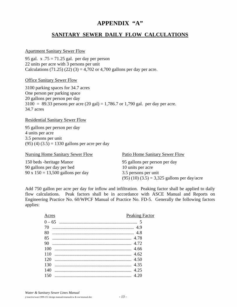
SANITARY SEWER DAILY FLOW CALCULATIONS Apartment Sanitary Sewer Flow
95 gal. x .75 = 71.25 gal. per day per person 22 units per acre with 3 persons per unit Calculations (71.25) (22) (3) = 4,702 or 4,700 gallons per day per acre. Office Sanitary Sewer Flow
3100 parking spaces for 34.7 acres One person per parking space 20 gallons per person per day 3100 = 89.33 persons per acre (20 gal) = 1,786.7 or 1,790 gal. per day per acre. 34.7 acres Residential Sanitary Sewer Flow
95 gallons per person per day 4 units per acre 3.5 persons per unit (95) (4) (3.5) = 1330 gallons per acre per day Nursing Home Sanitary Sewer Flow
150 beds -heritage Manor 90 gallons per day per bed 90 x 150 = 13,500 gallons per day
Patio Home Sanitary Sewer Flow
95 gallons per person per day 10 units per acre 3.5 persons per unit (95) (10) (3.5) = 3,325 gallons per day/acre
Add 750 gallon per acre per day for inflow and infiltration. Peaking factor shall be applied to daily flow calculations. Peak factors shall be in accordance with ASCE Manual and Reports on Engineering Practice No. 60/WPCF Manual of Practice No. FD-5. Generally the following factors applies:
Acres Peaking Factor 0 – 65 ................................................................... 5 70 ...................................................................... 4.9 80 ...................................................................... 4.8 85 .................................................................... 4.78 90 .................................................................... 4.72 100 .................................................................. 4.66 110 .................................................................. 4.62 120 .................................................................. 4.50 130 .................................................................. 4.35 140 .................................................................. 4.25 150 .................................................................. 4.20
Water & Sanitary Sewer Lines Manual j:\inactive\wax\1999-151 design manuals\manuals\w & ww\manual.doc - 14 -
APPENDIX “B”
TNRCC RULES FOR LIFT STATIONS