chirp signal-based aerial acoustic communication for …schoi/publication/conferences/... · chirp...
TRANSCRIPT

Chirp Signal-Based Aerial Acoustic Communicationfor Smart Devices
Hyewon Lee† ◦, Tae Hyun Kim◦, Jun Won Choi‡, and Sunghyun Choi††Seoul National University and INMC, ◦Soundlly, Inc, ‡Hanyang University
Email: [email protected], [email protected], [email protected], [email protected]
Abstract—Smart devices such as smartphones andtablet/wearable PCs are equipped with voice user interface, i.e.,speaker and microphone. Accordingly, various aerial acousticcommunication techniques have been introduced to utilize thevoice user interface as a communication interface. In thispaper, we propose an aerial acoustic communication systemusing inaudible audio signal for low-rate communication inindoor environments. By adopting chirp signal, which is widelyused for radar applications due to its capability of resolvingmulti-path propagation, the proposed acoustic modem supportslong-range communication independent of device characteristicsover severely frequency-selective acoustic channel. We alsodesign a backend server architecture to compensate for the lowdata rate of chirp signal-based acoustic modem. Via extensiveexperiments, we evaluate various characteristics of the proposedmodem including multi-path resolution and multiple chirp signaldetection. We also verify that the proposed chirp signal candeliver data at 16 bps in typical indoor environments, where itsmaximum transmission range is drastically extended up to 25 mcompared to the few meters of the previous research.
Index Terms—Chirp signal, aerial acoustic communication,smart devices, software-based digital modem.
I. INTRODUCTION
Today’s various communication technologies can be cate-gorized by the medium that is used to deliver informationfrom transmitter to receiver. Separate from common wirelesscommunication technologies such as WiFi and Bluetooth thatdeliver information through electromagnetic waves, acousticcommunication refers to the communication technology thatuses sound waves. Sound waves propagate through the me-chanical vibration of a medium (e.g., water or air), and theycan be transmitted and received by speakers and microphones.
Acoustic communication has been developed mainly forthe underwater communication of sensor networks to monitormarine ecosystems and the status of underwater platforms likeoil rigs [1, 2]. Digital modulation schemes that are used forelectromagnetic wave communications, e.g., phase/frequencyshift keying (PSK/FSK), can be applied to acoustic commu-nications to modulate sound signals [2]. Underwater acousticcommunication requires transceivers to operate in water, whichtypically means the use of special speakers and microphonemodules, i.e., hydrophones.
In contrast, aerial acoustic communication delivers infor-mation through airborne sound waves [3, 4]. Depending onthe operating frequency of aerial acoustic communication,the transceiver can be either an off-the-shelf device thatplays/records audio (under 22 kHz in general), or an ultra-sound transducer (over 22 kHz). It should be noted that the
aerial acoustic communication is versatile because any audiointerface-equipped device can be utilized as a communicationdevice, i.e., hardware and operating system (OS) independent.Moreover, it provides an alternative communication interfacefor smart devices along with WiFi and Bluetooth, whichoften are turned off in order to save battery and/or preventunintended connections. Given the widespread use of smartdevices that play, record, and process sound signals throughtheir voice user interface, aerial acoustic communication under22 kHz has recently been studied in depth [5–14].
However, the communication range of the previous work islimited to few meters, as the acoustic channels, composed ofspeaker, air medium, and microphone, are heavily frequencyselective. Moreover their signal modulation schemes do notwork well over such frequency selective channels. In thispaper, we focus on inaudible aerial acoustic communicationfor off-the-shelf audio interfaces in long-range indoor envi-ronments. Specifically, we assume that a speaker repeatedlybroadcasts short-length ID and a smart device decodes theacoustic signal. The contributions of the paper are three folds.
• By adopting chirp signal that was originally used in radarapplications [15], we drastically extend the communica-tion range up to 25 m at maximum. The chirp signal alsosupports most smart devices equipped with microphonesthat have very selective frequency responses.
• We propose a software digital modem for smartphonesthat can efficiently demodulate the chirp signal by com-bining fast Fourier transform (FFT) and Hilbert trans-form. The proposed envelope detector can also compen-sate for Doppler effect.
• In addition, we introduce a TV content recognition ser-vice as an example application. We also implement abackend query server in order to overcome the low datarate (approximately 16 bps).
The rest of the paper is organized as follows. In Section II,we first review the previous work and briefly evaluate theperformance of commonly used modulation schemes. Sec-tion III and Section IV present chirp signal in indoor acousticchannel and corresponding software modem for smart devices,respectively. We introduce a TV content recognition servicebased on the proposed modem and a backend server thatcompensates for the bit rate limitation in Section V. Throughextensive experimental results, we evaluate the performance ofthe proposed system in Section VI. Finally we conclude thepaper with discussion on the future work in Section VII.

II. RELATED WORK AND REVISIT OF PHY MODULATIONS
We investigate the previous research on aerial acousticcommunication and discuss their drawbacks. Our experimentalresults show that the limited performance is due mainly to thesignal modulation schemes.
A. Related Work
Aerial acoustic communication for data transmission amongaudio-enabled devices has been studied in depth [6–11]. In [6],multiple tones are used to transmit data at 5.6 kbps in anaudible mode (735∼4,410 Hz), or a single tone for 1.4 kbpsrate in an inaudible mode (18.4 kHz). Both modes work upto 2 m distance with line-of-sight (LOS) communication. M-ary FSK-based acoustic communication scheme, referred toas Digital Voice, is proposed in [7] to achieve data rates oftens to thousands of bps, where the frequency tones under12 kHz audible band are chosen to resemble the soundsof clarinets and birds. [8] implements orthogonal frequencydivision multiplex (OFDM) with binary and quadrature PSKmodulation schemes in the 6∼7 kHz band. The proposedsystem, Dhwani, aims to substitute near field communication(NFC) with a data rate of up to 800 bps in a very short range(less than 20 cm). NTT DoCoMo introduces Acoustic OFDMin [9] that hides approximately 240 bps of information in the6.4∼8 kHz band of existing sound sources. [10] similarly em-beds 600 bps data by modulating the phase of 6.4∼8 kHz bandvia modulated complex lapped transform. Due to the maskingeffect of the human hearing system, the embedded informationin [9, 10] cannot be heard by people. Commercial off-the-shelflaptops are used to build a mesh network via aerial acousticcommunications in [11], achieving a link distance and speedup to 20 m and 20 bps at maximum, respectively.
Commercial services using aerial acoustic communicationtechnologies have been also introduced by a number of start-ups [12–14]. SonicNotify has developed small beacon devicesthat repeatedly transmit high frequency inaudible tones [12].ShopKick is another start-up that is collaborating with retailstores such as Macy’s to provide special offers via inaudiblesignals generated by ultrasound transmitters [13]. Naratte is astart-up that introduced Zoosh as a substitute to NFC. This iscurrently being used by Verifone as a mobile payment servicefor taxis, referred to as Way2Ride [14].
The aforementioned work has a few limitations. In [6–8],the sound signals of aerial acoustic communication is withinthe audible band. This has two main drawbacks: (1) the soundsignals heard by human beings can be disruptive, and (2) thebackground noise in a typical environment distorts the acousticsignals. Acoustic signals designed in [9, 10] require an existingaudible sound source to embed the signal, and hence, are notstand-alone techniques. In addition, the modulation schemesin many of these examples have a limited transmission rangeof up to a few meters even in ling-of-sight (LOS) environment.The only exception is [11], but the speaker and microphone oflaptops used in the testbed have a very flat frequency responsein the high-frequency band, which is not the case in most audiointerfaces as presented in Section III-B.
0 0.3 0.6 0.9−pi/2
0
pi/2
pi
Time (sec)
Estim
ate
d p
hase (
rad)
(a) Optimus G2.
0 0.3 0.6 0.9−pi/2
0
pi/2
pi
Time (sec)
Estim
ate
d p
hase (
rad)
(b) Sky Vega Iron.
0 0.3 0.6 0.9−pi/2
0
pi/2
pi
Time (sec)
Estim
ate
d p
hase (
rad)
(c) Galaxy Note.
Fig. 1. Estimated phase shift of recorded sine tones in three differentsmartphone models. Phase basically drifts over time due to the samplingfrequency offset, while its variance differs by model.
Extending the communication range is important to enablevarious types of services using aerial acoustic communicationwith off-the-shelf loud speakers. Note that most commercialservices [12–14] employ specially designed transmitters toachieve a few meters of communication range.
B. Revisit of PHY modulation schemes
We revisit two widely used digital signal modulationschemes, namely, PSK and FSK, and discuss their limitationsin aerial acoustic communications for smart devices.
1) Phase shift keying: It is well known that PSK requiresexact carrier, sampling, and symbol timing recovery, and itsperformance degrades in time-varying fading channels [16].We here present the time-varying phase shift of aerial acousticchannel through a simple experiment. In a typical officeenvironment, we play a sine tone at 20 kHz center frequencyusing a reference speaker. Then we record the sine tone usingsmart devices at 12 m distance LOS channel.
Fig. 1 depicts the shift of the estimated phase (relativeto the first sample) that are simultaneously recorded every60 ms in three smart devices. Each line represents 50 it-erations of recording. Basically the estimated phase linearlydrifts over time due to the sampling frequency offset of themicrophone [8] (Fig. 1(a)). For some models, however, thephase shift is not always linear; in the worst case, the phaseshift is not predictable (Fig. 1(c)). This is due to the channelvariation as well as non-ideal local oscillator of smart devices.Hence we claim that PSK is not applicable for long-rangeaerial acoustic communication as the receiver requires phasecompensation algorithm such as phase locked loops, whichcomplicates the receiver architecture.
2) Frequency shift keying: FSK usually suffers from thefrequency selectivity, since constellation points of receivedtones are asymmetric [17]. We set an experiment to validatethe feasibility of FSK on aerial acoustic communication.Assuming binary FSK (BFSK), we sequentially play two typesof sine tones using a reference speaker in inaudible band; lowfrequency (19 kHz for bit 0) and high frequency (21 kHz forbit 1) tones. Smart devices record each tone for 100 times at12 m LOS channel, and we emulate non-coherent FSK receiverwith adaptive decision bound [17] using MATLAB to presentthe received constellation point in Fig. 2.
Fig. 2 presents constellation points of 16 BFSK symbolsreceived by three smart devices. The correlation of high and

0 4 8 12 16−0.6
0
0.6
Symbol index
Corr
ela
tion
High tone
Low tone
Adjusted decision bound
(a) Galaxy S3.
0 4 8 12 16−0.06
0
0.06
Symbol index
Corr
ela
tion
High tone
Low tone
Adjusted decision bound
(b) Sky Vega N6.
0 4 8 12 16−0.6
0
0.6
Symbol index
Corr
ela
tion
High tone
Low tone
Adjusted decision bound
(c) Galaxy Note2.
Fig. 2. Empirical constellation point of non-coherent BFSK receivers forthree different smart devices. High frequency tones are hard to be receiveddue to the frequency selectivity of microphones, so that adaptive decisionbound might fail.
low frequency tones are supposed to be the same in flat-frequency response. However, the constellation points areasymmetric due to the frequency selectivity of microphones,and hence, the receiver requires adaptive decision bound asshown in Fig. 2(a).1 In very frequency selective channels asin Figs. 2(b) and 2(c), however, the adaptive decision boundfails to demodulate the high frequency tones due to the severeloss. Therefore, FSK is not a good option for highly frequencyselective acoustic channel.
III. ACOUSTIC CHANNEL AND CHIRP SIGNAL
In this section, we first define the frequency band forinaudible aerial acoustic communication. Then, we measurethe frequency responses of speakers and microphones imple-mented in various smart devices, as well as the characteristicsof typical indoor acoustic channel. In order to cope with thesevere frequency selectivity and random phase distortion ofthe indoor acoustic channel, we adopt chirp signal for indooraerial acoustic communication.
A. Hearing threshold of human beings
As we aim to design inaudible acoustic signal, we theoreti-cally and empirically evaluate the maximum audible frequencyof human ears. Fig. 3(a) presents the theoretic hearing thresh-old measured at 1 m distance [18], where Terhardt modelover 16 kHz (vertical dashed line) shows estimated values.The sound pressure level that is required to stimulate cochlearvaries over frequency. For instance, at 18 kHz, the soundpressure level should be at least 100 dBSPL to be heard; this isequivalent to the loudness of a heavy metal concert, and hence,signal over 18 kHz is claimed to be mostly inaudible in typicalenvironments. To be more specific, we conduct an experimentwith 134 people to determine the maximum frequency they canhear through earphones. From Fig. 3(b), we choose 19.5 kHzas the lower frequency bound of inaudible sound signal. Sincethe sampling frequency of most audio interfaces is 44.1 kHz,we set the upper frequency bound as 22 kHz.
B. Frequency response of various audio interfaces
We measure the frequency responses of various audio inter-faces in an anechoic chamber. As reference speaker and micro-phone with flat frequency responses, we use Genelec 6010A
1We assume that the first four symbols are known in off-line for theadaptation of decision bound in this experiment.
5 10 15 20
0
50
100
150
200
250
Frequency (Hz)
Sound p
ressure
level (d
BS
PL)
Terhardt model
ISO 226:2003
ISO 226:1997
(a) Theoretic hearing threshold.
15 20 25 30 35 4014
16
18
20
22
Age
Ma
xim
um
au
dib
le f
req
ue
ncy (
kH
z)
(b) Empirical hearing threshold.
Fig. 3. Theoretic and empirical hearing threshold of human ears. Terhardtmodel in Fig. 3(a) is based on [19], and we obtain Fig. 3(b) via experimentwith randomly selected 134 people.
0 5 10 15 20 22−60
−50
−40
−30
−20
−10
0
Frequency (kHz)
Ga
in (
dB
)
Sky Vega Racer
Optimus LTE
Galaxy S3
Galaxy Note2
Galaxy Tab
Galaxy Note 10.1
iPad Mini
iPad 4G
iPhone 4G
iPhone 5G
Genelec 6010A
Pascom KWS−10H
JE 602F8
SPA 165B55
(a) Frequency response of speakers.
0 5 10 15 20 22−60
−50
−40
−30
−20
−10
0
Frequency (kHz)
Gain
(dB
)
Sky Vega Racer
Optimus LTE
Galaxy S3
Galaxy Note2
Galaxy Tab
Galaxy Note 10.1
iPad Mini
iPad 4G
iPhone 4G
iPhone 5G
(b) Frequency response of microphones.
Fig. 4. Frequency response of speaker and microphones of various smartdevices and off-the-shelf speakers. Speakers are shown to be more frequencyselective than microphones in general, and the selectivity of microphones issevere over 21 kHz.
active speaker and Audix TM1 condenser microphone. Adopt-ing linear frequency sweep (LFS) signal method proposedin [20], we play 50 sec sine signal linearly sweeping from20 to 22,000 Hz via reference (or smart device/off-the-shelf)speaker, and record the sound using smart device (or referencemicrophone). Then we post-process the recorded audio usingMATLAB to calculate the frequency response.
Comparing Figs. 4(a) and 4(b), we observe that speakersare more frequency selective than microphones in general. Wealso note that some smart devices can hardly record signalsover 21 kHz. From Fig. 4, we conclude that inaudible acousticcommunication in 19.5∼22 kHz band is mostly feasible,though it has to overcome the severe frequency selectivity ofaudio interfaces.
C. Delay spread of acoustic channel
Now we measure the impulse responses of aerial acousticchannels in a typical indoor office environment. We againadopt LFS signal method in [20]. We play LFS signal usingGenelec 6010A and JE602F8 speakers for LOS and non-LOS (NLOS) acoustic channel, respectively, and record withvarious smart devices which are randomly located within 5 mdistance from the speaker. From Fig. 5, we observe thatthe indoor aerial acoustic channel suffers from severe multi-path propagation. Especially in NLOS case, multi-path delayextends up to 40 ms for −6 dBr threshold. Therefore oneneeds guard interval between symbols or a channel equalizerin order to avoid inter-symbol interference (ISI).

−0.02 −0.01 0 0.01 0.02 0.03 0.04 0.05 0.06 0.07 0.08−12
−9
−6
−3
0
Time (sec)
Impuls
e r
esponse (
dB
r)
Sky Vega Racer
Sky Vega Iron
Optimus G Pro
Optimus LTE
Galaxy Note
Galaxy R
Galaxy S3
Galaxy Note2
Galaxy Tab
Galaxy Note 10.1
(a) Delay spread of LOS acoustic channel.
−0.02 −0.01 0 0.01 0.02 0.03 0.04 0.05 0.06 0.07 0.08−12
−9
−6
−3
0
Time (sec)
Impuls
e r
esponse (
dB
r)
Sky Vega Racer
Sky Vega Iron
Optimus G Pro
Optimus LTE
Galaxy Note
Galaxy R
Galaxy S3
Galaxy Note2
Galaxy Tab
Galaxy Note 10.1
(b) Delay spread of NLOS acoustic channel.
Fig. 5. Impulse responses of aerial acoustic channels in indoor officeenvironment, measured using LFS signal [20]. Each measurement is repeated10 times at random locations within 5 m.
0 0.005 0.01 0.015 0.02−1
0
1
Time (s)
Am
plit
ud
e
(a) Up chirp.
0 0.005 0.01 0.015 0.02−1
0
1
Time (s)
Am
plit
ud
e
(b) Down chirp.
0 0.01 0.02 0.03 0.04−1
0
1
Time (s)
Co
rre
latio
n
(c) Auto correlation.
0 0.01 0.02 0.03 0.04−1
0
1
Time (s)
Co
rre
latio
n
(d) Cross correlation.
Fig. 6. An example of a pair linear chirps, sweeping from 500 to 1500 Hzwith 20 ms symbol duration, and their auto and cross correlations.
D. Chirp binary orthogonal keying
The signal modulation scheme for aerial acoustic commu-nication should be robust to the frequency selectivity, andsymbol/sampling timing offset. As a solution, we adopt chirpsignal [15]. Different from PSK and FSK signal which havetime invariant frequency for a specific symbol, the frequencyof a chirp symbol varies over time; up chirp and down chirphave increasing and decreasing frequencies, respectively, asshown in Fig. 6. Up and down chirps use the same frequencyband, and hence, the frequency selectivity of acoustic channeldistorts both up and down chirp symbols in a symmetricmanner, which is not the case in FSK. We can also designa non-coherent demodulator which is robust to timing offsetand Doppler shift [15], as to be discussed in Section IV.
As a chirp signal has good auto correlation characteristic(Figs. 6(c) and 6(d)), it has been widely used for radarapplications as well as localizations [21, 22]. Based on thefact that up and down chirps are nearly orthogonal, theauthors in [16, 23, 24] also propose chirp binary orthogonalkeying (BOK) for wireless communications. [25, 26] usesacoustic chirp signals to measure the distance between speakerand microphone. To our best knowledge, however, this isthe first literature that applies chirp BOK to aerial acousticcommunication in order to cope with the frequency selectiveand time-varying acoustic channel.
A pair of chirp signals in frequency band [f1, f2] Hz is
defined as
s1 (t) = cos(2πf1t+ µt2/2 + φ0
), (1)
s2 (t) = cos(2πf2t− µt2/2 + φ0
), 0 ≤ t ≤ T, (2)
for Symbol 1 (up chirp) and Symbol 2 (down chirp), re-spectively, where T is symbol duration, and φ0 is arbitraryinitial phase which is assumed to be zero without loss ofgenerality. µ is referred to as chirp sweep rate in bandwidthB (= f2−f1), i.e., µ = 2πB/T . In the following section, wedescribe the acoustic modem architecture with matched filterfor chirp BOK in detail, and discuss implementation issues insmart devices.
IV. SOFTWARE RECEIVER FOR CHIRP BOK SIGNAL
We demonstrate the receiver architecture of chirp signals forsmart devices. Due to the limitation of the computing powerof smartphone, we keep the receiver architecture as simple andefficient as possible.
A. Matched filter and envelope detection
A common method to implement the matched filter (orequivalently, correlator) receiver is convolution. Received sig-nal r (t) is convolved with time-reversed versions of s1 (t) ands2 (t) to generate estimator c1 and c2, respectively, that is,
c1,2 =
∫r (τ) s1,2 (T − τ) dτ. (3)
If c1 > c2, the receiver estimates that Symbol 1 is transmitted,and Symbol 2 otherwise.
The aerial acoustic communication is based on sound sig-nals; the received signal r (t) is obtained from recordingprocess in OS kernel. Since the internal delay that takesto fetch recorded data from audio buffer cannot be tightlycontrolled, symbol-by-symbol recording might lose some ofthe acoustic signals in between recordings. Instead, we designthe modem to process multiple symbols in a single recordingwith long duration. One problem of this bulk processing isthe complexity of convolution (O
(n2)). We can simplify the
matched filter using FFT with complexity O (n log n), i.e.,
c1,2 = F−1{F{r (t)}F{s1,2 (T − t)}
}, (4)
where F and F−1 denote FFT and inverse FFT (IFFT),respectively.
Fig. 7 depicts an example of the bulk audio signal pro-cessing, assuming that the received symbols are [up, down,up, down] chirps. Fig. 7(b) and Fig. 7(c) are obtained byconvolving Fig. 7(a) with the time-reverse of up chirp anddown chirp, respectively. Obviously the receiver can recoverthe transmitted symbols by comparing correlation peaks every20 ms, i.e., symbol duration. We can efficiently find thecorrelation peaks of chirp signals as follows.
We can write the close-form auto correlation as
ψ (t) = T(
1− |t|T
)sinc
[πB(
1− |t|T
)]cos (2πf1t) ,
, e (t) cos (2πf1t) , (5)

0 0.02 0.04 0.06 0.08−1
0
1
UpChirp
DownChirp
UpChirp
DownChirp
Time (s)
Am
plit
ude
(a) An example of received chirp symbols.
0 0.02 0.04 0.06 0.08−1
0
1
Time (s)
Corr
ela
tion
(b) Up chirp correlation.
0 0.02 0.04 0.06 0.08−1
0
1
Time (s)
Corr
ela
tion
(c) Down chirp correlation.
0.018 0.0185 0.019 0.0195 0.02 0.0205 0.021 0.0215 0.022−1
0
1
Time (s)
Corr
ela
tion
Correlation
Envelope
(d) Up chirp correlation magnified around 20 ms.
Fig. 7. An example of received chirp symbols and corresponding matchedfilter receiver. The receiver can demodulate chirp signals by comparing thecorrelation peaks every 20 ms, where the peaks can easily be read fromenvelopes.
which is a form of cosine-modulated time-decaying sinc func-tion [15]. Due to the oscillating term cos (2πf1t) in Eq. (5), itis not easy to read clear peak values as shown in Fig. 7(d). Wecan smooth the auto correlation curve by finding its envelope.Eq. (5) is very similar to an amplitude modulated (AM) signalwith carrier frequency of f1. Therefore, its envelope e (t) canbe obtained via Hilbert transform [27] as follows.
|e (t)| = |e (t) [cos (2πfct) + sin (2πfct)]| ,
=∣∣∣ψ (t) + ψ̂ (t)
∣∣∣ , (6)
where ˆ denotes Hilbert transform that can be calculatedfrom FFT. More into detail, let Ψ [w] and Ψ̂ [w] be FFTrepresentations of ψ (t) and ψ̂ (t), respectively. Note that
Ψ̂ [w] = − sgn [w] Ψ [w] , (7)
where sgn [ω] is a signum function, i.e.,
sgn [w] =
1, w > 0,0, w = 0,−1, w < 0.
(8)
Hence, the right-hand-side of Eq. (6) is rewritten as
|e (t)| =∣∣∣ψ (t) + ψ̂ (t)
∣∣∣ ,=∣∣∣F−1{Ψ [w] + Ψ̂ [w]}
∣∣∣ ,=∣∣F−1{2Ψ [w]u [w]}
∣∣ , (9)
where u [w] is unit step function that u [w] = 1 for w > 0and u [w] = 0 otherwise. It should be noted that we adoptFFT for convolution of received audio and up/down chirps.Therefore the envelopes in Eq. (9) can be easily detectedafter the convolution. Fig. 9(a) depicts the block diagram ofenvelope detector.
0 0.005 0.01 0.015 0.02−1
0
1
Time (s)
Am
plit
ude
(a) Chirp symbol shapedby raised cosine window.
18 19 20 21 22 23 24−90
−60
−30
0
Frequency (kHz)
Ga
in (
dB
r)
(b) Power spectral densityof shaped chirp symbol.
0 0.1 0.2 0.3 0.4 0.5 0.6 0.7 0.8 0.9 1 1.1−1
0
1
Time (s)
Am
plit
ud
e
Preamble 1 2 3 4 5 6 7 8 9 10 11 12 13 14 15 16
(c) Frame structure.
Fig. 8. Envelope of raised cosine window for chirp symbol shaping. We setroll-off factor to 0.1 for −10 dB spectral masking at frequency boundaries.A frame begins with a preamble (long-chirp as a delimiter), and is followedby 16 data symbols. Each symbol is separated by 40 ms guard interval.
TABLE ISYSTEM PARAMETERS
Parameter Value Number of [email protected] kHz @48 kHz
Frequency band 19.5∼22 kHz - -Symbol duration 20 ms 882 960Guard interval 40 ms 1764 1,920
Preamble 100 ms 4,410 4,800Number of bits per frame 16 bits - -
Frame size 1.1 sec 48,510 52,800FFT size 65,536 point - -
Raised cosine filter roll-off 0.1 - -
B. Preamble design and system parameters
Considering the communication scenario, i.e., chirp signalsfor short ID broadcast, we assume that 16 bit ID is repeatedlyplayed by speakers. In order for the receiver to find thebeginning of a 16 bit ID, we deploy 0.1 sec up chirp signalas a preamble that can be also used as a frame delimiter. Inaddition, indoor acoustic channel typically suffers from multi-paths as discussed in Section III, and hence, we insert 40 msguard interval between symbols (Fig. 8(c)). For 65,536 sizeFFT operation at 44.1 kHz or 48 kHz sampling rate, whichare the most common sampling rates in audio interfaces, weset the symbol duration to 20 ms. Each data symbol is shapedusing raised cosine window with roll-off factor 0.1 as shownin Fig. 8. The raised cosine window, which also works as aningress filter at matched filter, is designed to reduce (1) out-of-band leakage to −10 dB at frequency boundaries and (2)ringing and rising effects at speakers and microphones [8].Table I summarizes system parameters used in our design.
C. Receiver process and architecture
1) Recording: A receiver begins signal reception by record-ing. Considering 1.1 sec frame duration and 0.1 sec preamble,we set the recording size as 1.2 sec. This guarantees that theaudio data includes at least one fully-recorded preamble.
2) Preamble detection: The receiver then searches thepreamble in the recorded audio by envelope detection basedon Eq. (9) as follows: (i) calculate FFT of recorded audio(R) and preamble (P); (ii) multiply R and P , and substitutenegative frequency terms to zero;2 (iii) IFFT and take absolute
2The scalar factor 2 in Eq. (9) is omitted here for simplicity.
Divider
Zero-
filling
Appender
Envelope Detector
[0:N/2-1]
[N/2:N-1] N-point
IFFTAbsolute
Recorded audio
Chirp symbols
Output
N-point
FFT
N-point
FFT
(a) Block diagram of envelope detector.
RecordingEnvelope
Detector
Time-reversed
Preamble
Envelope
Detector1001 0101
0011 1100
16 Bit
DataComparer
Symbol
Sampler
Time-reversed
Up Chirp
Time-reversed
Down Chirp
Envelope
Detector
Preamble Detection
Symbol Demodulation
Preamble offset
Max.
Finder
(b) Block diagram of receiver.
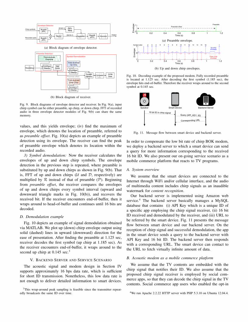
Fig. 9. Block diagrams of envelope detector and receiver. In Fig. 9(a), inputchirp symbol can be either preamble, up chirp, or down chirp. FFT of recordedaudio in three envelope detector modules of Fig. 9(b) can share the samememory.
values, and this yields envelope; (iv) find the maximum ofenvelope, which denotes the location of preamble, referred toas preamble offset. Fig. 10(a) depicts an example of preambledetection using its envelope. The receiver can find the peakof preamble envelope which denotes its location within therecorded audio.
3) Symbol demodulation: Now the receiver calculates theenvelopes of up and down chirp symbols. The envelopedetection in the previous step is repeated, where preamble issubstituted by up and down chirps as shown in Fig. 9(b). Thatis, FFT of up and down chirps (U and D, respectively) aremultiplied by R instead of that of preamble (P). Beginningfrom preamble offset, the receiver compares the envelopesof up and down chirps every symbol interval (upward anddownward triangle marks in Fig. 10(b)), and recovers thereceived bit. If the receiver encounters end-of-buffer, then itwraps around to head-of-buffer and continues until 16 bits aredecoded.
D. Demodulation example
Fig. 10 depicts an example of signal demodulation obtainedvia MATLAB. We plot up (down) chirp envelope output usingsolid (dashed) lines in upward (downward) direction for theease of presentation. After finding the preamble at 1.125 sec,receiver decodes the first symbol (up chirp at 1.185 sec). Asthe receiver encounters end-of-buffer, it wraps around to thesecond up chirp at 0.145 sec.3
V. BACKEND SERVER AND SERVICE SCENARIO
The acoustic signal and modem design in Section IVsupports approximately 16 bps data rate, which is sufficientfor short ID transmission. Nonetheless, this low data rate isnot enough to deliver detailed information to smart devices.
3This wrap-around peak sampling is feasible since the transmitter repeat-edly broadcasts the same ID over time.
0 0.2 0.4 0.6 0.8 1 1.20
1 Preamble
Preamble offset
Time (s)
En
ve
lop
e
(a) Preamble envelope.
0 0.2 0.4 0.6 0.8 1 1.21
0
1Symbol order 12 3 4 5 6 7 8 9 10 11 12 13 14 15 16
Time (s)
Envelo
pe
Up chirpenvelope
Down chirpenvelope
(b) Up and down chirp envelopes.
Fig. 10. Decoding example of the proposed modem. Fully recorded preambleis located at 1.125 sec. After decoding the first symbol (1.185 sec), theenvelope hits end-of-buffer. Therefore the receiver wraps around to the secondsymbol at 0.145 sec.
Speaker Smart Device Backend Server
16 bit ID in chirp signalQuery {API_KEY, ID}
Corresponding URL
Fig. 11. Message flow between smart device and backend server.
In order to compensate the low bit rate of chirp BOK modem,we deploy a backend server to which a smart device can senda query for more information corresponding to the received16 bit ID. We also present our on-going service scenario as amobile commerce platform that reacts to TV programs.
A. System overview
We assume that the smart devices are connected to theInternet through WiFi and/or cellular interface, and the audioof multimedia content includes chirp signals as an inaudiblewatermark for content recognition.
Our backend server is implemented using Amazon webservice.4 The backend server basically manages a MySQLdatabase that contains (i) API Key which is a unique ID ofa specific app employing the chirp signal receiver, (ii) 16 bitID received and demodulated by the receiver, and (iii) URL tobe referred by the smart device. Fig. 11 presents the messageflow between smart device and our backend server. On thereception of chirp signal and successful demodulation, the appin the smart device sends a query to the backend server withAPI Key and 16 bit ID. The backend server then respondswith a corresponding URL. The smart device can contact tothe URL to fetch virtually infinite amount of data.
B. Acoustic modem as a mobile commerce platform
We assume that the TV contents are embedded with thechirp signal that notifies their ID. We also assume that theproposed chirp signal receiver is employed by social com-merce apps, so that they can decode the chirp signal in the TVcontents. Social commerce app users who enabled the opt-in
4We run Apache 2.2.22 HTTP server with PHP 5.3.10 on Ubuntu 12.04.4.

chirp signal receiver can pervasively receive the informationof product placement (PPL) during and/or after watching TV.
A challenge of this service is battery consumption issue ofsmart devices. Continuously recording and processing audiosignal for 24 hours is not feasible since it would consumelarge amount of energy. Instead, we implement schedulingfunctionality for the chirp signal receiver, so that the appscan be scheduled to activate the receiver process based onthe time table of TV programs. For instance, to check if auser actually watched an one-hour TV program, it would beenough to record and process audio signal every 3 minutes.Our experiment has shown that the receiver process consumesonly 1% more battery energy when the processing interval is3 minutes, where the detailed results are omitted in the paperdue to the lack of space.
Another technical issue of chirp signal is encoding loss.Going through the TV encoder, the acoustic signal embeddedin audio content could be partially lost due to the lossyencoding. Typical TV audio encoders such as advanced audiocoding (AAC) and Dolby digital (AC3) have cut-off frequencyaround 21 kHz, where the detailed threshold varies dependingon the bit-rate settings. Note that, however, partial frequencyloss of the encoding process is similar to the effect of speakerand microphone’s frequency response, and hence, we expectthat the chirp signal can be delivered through the TV network.Leaving the field test through the actual TV network as ourfuture work, we present in-lab test results below.
VI. PERFORMANCE EVALUATION
We present experimental results and validate the perfor-mance of the proposed chirp BOK modem for smart devices.We implement our chirp BOK modem on various Androiddevices with OS version from Froyo (Android 2.2) to Kitkat(Android 4.4). Most experiments are conducted in a staticindoor office environment unless mentioned otherwise.
A. Transmission range in indoor environmentWe first verify the maximum transmission range of the
proposed modem. We deploy Genelec 6010A speaker and15 different smartphones at the end side of 25 m corridorwith 2.5 m width and 3 m height. MacBook Air laptop playswave audio file through the Genelec 6010A speaker, wherethe volumes of laptop and speaker are set to 50%.
Fig. 12 presents the success probability of signal reception,averaged over 300 repetitions of 16 bit ID reception. It can beobserved that most devices can successfully receive the chirpsignal with 97% probability, which verifies that the proposedmodem works in long transmission range. The low successrate of Galaxy Tab is due to its low volume of recording,as shown in Fig. 4(b). Considering the received audio level isapproximately 10 dBSPL at 20 kHz, we expect that increasingthe audio output level could further increase the transmissionrange.
B. Effect of lossy encodingIn order to study the effect of lossy encodings on the signal
reception probability, we play chirp signals using a Samsung
0 20 40 60 80 100
Vega N6
Vega Iron
Vega Racer
Optimus G2
Optimus G Pro
Galaxy Tab
Galaxy Note10.1
Galaxy Note3
Galaxy Note2
Galaxy Note
Galaxy S4
Galaxy S3
Success rate (%)
25 m
10 m
Fig. 12. Success probability of sig-nal reception at 10 m and 25 mdistances for various smart devices.Most devices can decode the trans-mitted signal with 97% probabilityat these distances.
0 20 40 60 80 100
Vega N6
Vega Iron
Vega Racer
Optimus G2
Optimus G Pro
Galaxy Tab
Galaxy Note10.1
Galaxy Note3
Galaxy Note2
Galaxy Note
Galaxy S4
Galaxy S3
Success rate (%)
AAC
AC3
WAV
Fig. 13. Success rate of signal re-ception for AAC, AC3, and WAVaudio formats in 5 m distance exper-iment. WAV and AC3 files performthe same, while the success rate ofAAC is worse due to the signal lossin its frequency response.
smart TV (UN46F8000). Three different types of audio filesare used for the experiment; loss-less wave format (i.e., WAV),and AC3 and AAC for lossy codec.
Fig. 13 presents the experimental results in a 5 m distanceindoor environment. The direct path between TV and smartdevices are partially blocked by partition screens. In case ofWAV and AC3 formats, we observe that chirp signals can besuccessfully delivered despite of the partition screens due tothe diffraction of sound waves. For AC3 format, however, thesuccess rate degrades in Vega Iron, Optimus G Pro, and GalaxyNote2 models. This is due to the signal loss of AC3 encoding.As those models have small frequency gain in high frequencyband, they sensitively reacts to the loss of high frequencysignal compared to the others. Nonetheless, we claim that theencoded chirp signals can reach the smart devices throughTV audio format with acceptable success probability in mostcases.
C. Multi-path resolution
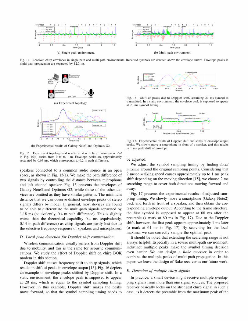
One of the reasons why chirp signal is robust in indoor envi-ronments is its capability of resolving multi-paths. Figs. 14(a)and 14(b) depict the envelopes at the chirp signal receiver inindoor single-path and multi-path environments, respectively.The envelope peaks in single-path environment clearly appear.The clustered peaks in Fig. 14(b) are separated by 12.7 ms(equivalently, 4.3 m path difference for 340 m/s propagationspeed of sound). The receiver can differentiate the mingledsignal from the envelope, and successfully recover the receivedsymbols in multi-path environment.
More into detail, chirp signals sweeping B Hz can resolvetwo different chirp signals traversing with 1/B sec pathdifference [15]. Considering 2.5 kHz bandwidth of our signaldesign, the proposed chirp BOK modem can differentiate0.4 ms difference of multi-path delays in an ideal case, whichis equivalent to 0.14 m path difference. In practice, however,this could be worse due to the decreased chirp sweeping bandcaused by frequency selectivity, as shown in Fig. 15.
In order to assess the capability of multi-path resolution,we emulate the multi-path propagation of sound waves byusing stereo speakers. We play chirp preamble through stereo
0 0.2 0.4 0.6 0.8 1 1.21
0
1
Time (sec)
En
ve
lop
e
Rx Symbol
Preamble1 0 0 1 0 1 1 0 1 0 10 0 0 1 1
Preamble
Up chirp
Down chirp
(a) Single-path environment.
0 0.2 0.4 0.6 0.8 1 1.21
0
1
Time (sec)
En
ve
lop
e
Rx Symbol
Preamble1 0 0 1 0 1 1 0 1 0 1 00 0 1 1
12.7 msecPreamble
Up chirp
Down chirp
(b) Multi-path environment.
Fig. 14. Received chirp envelopes in single-path and multi-path environments. Received symbols are denoted above the envelope curves. Envelope peaks inmulti-path propagation are separated by 12.7 ms.
(1 + d) m
1 m
30o
Stereo speaker
(left channel)
Stereo speaker
(right channel)
Audiosource(laptop)
L
R
(a) Experiment topology.
0
1
0.63 msec
−2 −1.5 −1 −0.5 0 0.5 1 1.5 2 2.5 3 3.5 40
1
Time (msec)
0.64 msec
∆ d =0 m
∆ d =0.2 m
∆ d =0.4 m
∆ d =0.6 m
∆ d =0.8 m
∆ d =1 m
En
ve
lop
e
Galaxy Note3
Optimus G2
(b) Experimental results of Galaxy Note3 and Optimus G2.
Fig. 15. Experiment topology and results in stereo chirp transmission. ∆din Fig. 15(a) varies from 0 m to 1 m. Envelope peaks are approximatelyseparated by 0.64 ms, which corresponds to 0.2 m path difference.
speakers connected to a common audio source in an openspace, as shown in Fig. 15(a). We make the path difference oftwo signals by controlling the distance between microphoneand left channel speaker. Fig. 15 presents the envelopes ofGalaxy Note3 and Optimus G2, while those of the other de-vices are omitted as they have similar patterns. The minimumdistance that we can observe distinct envelope peaks of stereosignals differs by model. In general, most devices are foundto be able to differentiate the multi-path signals separated by1.18 ms (equivalently, 0.4 m path difference). This is slightlyworse than the theoretical capability 0.4 ms (equivalently,0.14 m path difference) as chirp signals are partly lost due tothe selective frequency response of speakers and microphones.
D. Local peak detection for Doppler shift compensation
Wireless communication usually suffers from Doppler shiftdue to mobility, and this is the same for acoustic communi-cations. We study the effect of Doppler shift on chirp BOKmodem in this section.
Doppler shift causes frequency shift to chirp signals, whichresults in shift of peaks in envelope output [15]. Fig. 16 depictsan example of envelope peaks shifted by Doppler shift. In astatic environment, the envelope peak is supposed to appearat 20 ms, which is equal to the symbol sampling timing.However, in this example, Doppler shift makes the peaksmove forward, so that the symbol sampling timing needs to
0.018 0.0185 0.019 0.0195 0.02 0.0205 0.0210
0.5
1Sampling point
Time (sec)
En
ve
lop
e
0 m/sec
0.5 m/sec
1 m/sec
2 m/sec
Fig. 16. Shift of peaks due to Doppler shift, assuming 20 ms symbol istransmitted. In a static environment, the envelope peak is supposed to appearat 20 ms symbol timing.
0 0.06 0.121
0
1
Relative time from Preamble (sec)
En
ve
lop
e
Preamble
Adjusted sampling point
Multi−path componentOriginal sampling point
Symbol 1 Symbol 2
Up chirp
Down chirp
Fig. 17. Experimental results of Doppler shift and shifts of envelope outputpeaks. We slowly move a smartphone in front of a speaker, and this resultsin 1 ms peak shift of envelope.
be adjusted.We adjust the symbol sampling timing by finding local
maxima around the original sampling points. Considering that2 m/sec walking speed causes approximately up to 1 ms peakshift depending on the moving direction [15], we choose 2 mssearching range to cover both directions moving forward andaway.
Fig. 17 presents the experimental results of adjusted sam-pling timing. We slowly move a smartphone (Galaxy Note2)back and forth in front of a speaker, and then obtain the cor-responding envelope output. According to the frame structure,the first symbol is supposed to appear at 60 ms after thepreamble (x mark at 60 ms in Fig. 17). Due to the Dopplershift, however, the first peak appears approximately 1 ms later(o mark at 61 ms in Fig. 17). By searching for the localmaxima, we can correctly sample the optimal peak.
It should be noted that extending the searching range is notalways helpful. Especially in a severe multi-path environment,indistinct multiple peaks make the symbol timing decisioneven harder. We can design a Rake receiver in order tocombine the multiple peaks of multi-path propagation. In thispaper, we leave the design of Rake receiver as our future work.
E. Detection of multiple chirp signals
In practice, a smart device might receive multiple overlap-ping signals from more than one signal sources. The proposedreceiver basically locks on the strongest chirp signal in such acase, as it detects the preamble from the maximum peak of the

TABLE IIDETECTION RATES OF TWO-SIGNAL SCENARIO (L/R)
Time offset ∆t (ms)0 20 40 60 120
Amplitude 0 0.11/0.1 0.48/0.52 0.02/0.98 0.01/0.88 0.01/0.99difference 1 0/0.99 0/1 0/1 0/0.99 0/1
(dB) 3 0/1 0/1 0/1 0/1 0/1
envelope. We here present the experimental results with twosignal sources and examine the feasibility of multiple signaldetection.
We set an experiment in Fig. 15(a), where d = 0 and playdifferent signal sources in left and right channels. The stereosignal sources are skewed by ∆t ms and the right channelsignal is greater than the left channel one by 0 ∼ 3 dB. Thisemulates two chirp signals arriving at a smart device with timeand amplitude difference in practice.
Table II summarizes the detection probability of left andright channel signals (L/R) out of 100 signal receptions. Weverify that the proposed receiver detects the strongest signalin most cases. The exception is when two signals have exactlythe same amplitude and precisely overlapping data symbols,which is very unlikely to happen in practice. The receptionrates of the left and right channels in the 0 dB case with ∆t ≥40 ms time offset are uneven as we cannot perfectly matchthe signal strengths of two channels. Very small differenceof signal strengths makes the receiver sensitively stick to thestronger signal (the right channel in this experiment). When theamplitude difference is 0 dB, some overlapping data symbolsare lost in the 60 ms case as their preambles are partiallyoverlapping. We can verify this from the result of 120 mswhere the fully distinct preambles differentiate the overlappingdata symbols. This trend repeats until ∆t = 1.1 s, which isequivalent to ∆t = 0 ms considering the frame duration, wherewe omit the results here due to the lack of space. Therefore,we claim that the proposed receiver works well in multiple-signal environments.
VII. CONCLUSION AND FUTURE WORK
In this paper, we propose chirp signal-based aerial acous-tic communication technique for smart devices. Consideringsevere multi-path propagation of indoor acoustic channel aswell as device-dependent frequency selectivity, we adopt chirpsignal for indoor acoustic communication. The proposed chirpBOK modem architecture can deliver information at approxi-mately 16 bps up to 25 m distance with 97% success rate formost smart devices, and overcome Doppler shift by adjustingtime points for symbol sampling. The chirp signals are alsoshown to be able to pass through lossy audio codecs suchas AC3 and AAC. We additionally design backend serverarchitecture to make up the low data rate of the proposedacoustic software modem.
In the future, we plan to design an equalizer and Rake re-ceiver that can cope with multi-path propagation. It is expectedto shorten and/or remove 40 ms guard intervals in the currentframe structure such that the data rate can be enhanced. We arealso developing combined decoder to improve the decoding
capability, based on the fact that transmitter is assumed tobroadcast the same bits repeatedly over time.
ACKNOWLEDGEMENT
The authors sincerely thank to Kyung-Kuk Lee, CEO of Orthotronin Korea, for his in-depth technical discussion on chirp signals.
REFERENCES[1] M. Stojanovic and J. Preisig, “Underwater acoustic communication
channels: propagation models and statistical characterization,” IEEECommun. Mag., vol. 47, no. 1, pp. 84–89, 2009.
[2] I. F. Akyildiz, D. Pompili, and T. Melodia, “Underwater acoustic sensornetworks: research challenges,” Ad Hoc Networks, vol. 3, no. 3, pp.257–279, 2005.
[3] C. V. Lopes and P. M. Aguiar, “Acoustic modems for ubiquitouscomputing,” IEEE Pervasive Comput., vol. 2, no. 3, pp. 62–71, 2003.
[4] A. Madhavapeddy, R. Sharp, D. Scott, and A. Tse, “Audio networking:the forgotten wireless technology,” IEEE Pervasive Comput., vol. 4,no. 3, pp. 55–60, 2005.
[5] C. Peng, G. Shen, Y. Zhang, Y. Li, and K. Tan, “BeepBeep: a highaccuracy acoustic ranging system using cots mobile devices,” in Proc.ACM SenSys, 2007, pp. 1–14.
[6] V. Gerasimov and W. Bender, “Things that talk: using sound for device-to-device and device-to-human communication,” IBM Systems Journal,vol. 39, no. 3.4, pp. 530–546, 2000.
[7] C. V. Lopes and P. M. Aguiar, “Aerial acoustic communications,” inProc. IEEE WASPAA, 2001, pp. 219–222.
[8] R. Nandakumar, K. K. Chintalapudi, V. Padmanabhan, and R. Venkate-san, “Dhwani: secure peer-to-peer acoustic NFC,” in Proc. ACM SIG-COMM, 2013, pp. 63–74.
[9] H. Matsuoka, Y. Nakashima, and T. Yoshimura, “Acoustic communica-tion system using mobile terminal microphones,” NTT DoCoMo Tech.J, vol. 8, no. 2, pp. 2–12, 2006.
[10] H. S. Yun, K. Cho, and N. S. Kim, “Acoustic data transmission basedon modulated complex lapped transform,” IEEE Signal Processing Lett.,vol. 17, no. 1, pp. 67–70, 2010.
[11] M. Hanspach and M. Goetz, “On covert acoustical mesh networks inair,” J. of Commun., vol. 8, no. 11, 2013.
[12] SonicNotify. [Online]. Available: sonicnotify.com/[13] ShopKick. [Online]. Available: www.shopkick.com[14] Zoosh. [Online]. Available: www.verifone.com/industries/taxi/way2ride/[15] C. E. Cook, “Linear FM signal formats for beacon and communication
systems,” IEEE Trans. Aerosp. and Electron. Syst. Mag., no. 4, pp. 471–478, 1974.
[16] A. J. Berni and W. Gregg, “On the utility of chirp modulation for digitalsignaling,” IEEE Trans. Commun., vol. 21, no. 6, pp. 748–751, June1973.
[17] A. Viterbi, “Optimum detection and signal selection for partially coher-ent binary communication,” IEEE Trans. Inform. Theory, vol. 11, no. 2,pp. 239–246, 1965.
[18] B. C. J. Moore, An introduction to the psychology of hearing, 5th ed.Academic Press San Diego, 2003.
[19] E. Terhardt, “Calculating virtual pitch,” Hearing research, vol. 1, no. 2,pp. 155–182, 1979.
[20] A. Farina, “Simultaneous measurement of impulse response and distor-tion with a swept-sine technique,” in Proc. Audio Engineering SocietyConvention, 2000.
[21] C. E. Cook and M. Bernfeld, Radar signals: an introduction to theoryand application. Academic House, 1967.
[22] IEEE 802.15.4a, Part 15.4: Low-Rate Wireless Personal Area Networks(LR-WPANs), Chirp Spread Spectrum PHY Layer, IEEE Std., 2007.
[23] M. R. Winkley, “Chirp signals for communications,” in WESCONConvention Record, vol. 14, no. 2, 1962.
[24] S. E. El-Khamy, S. E. Shaaban, and E. Tabet, “Efficient multiple-accesscommunications using multi-user chirp modulation signals,” in Proc.IEEE ISSSTA, vol. 3, 1996, pp. 1209–1213.
[25] P. Lazik and A. Rowe, “Indoor pseudo-ranging of mobile devices usingultrasonic chirps,” in Proc. ACM SenSys, 2012.
[26] Acoustic Ruler. [Online]. Available:https://iqtainment.wordpress.com/acoustic-ruler/
[27] R. N. Bracewell and R. Bracewell, The Fourier transform and itsapplications. McGraw-Hill New York, 1986.