idt2014 chirp presentation
TRANSCRIPT
Confidential © ams AG 2014
Filter Characterization using a Chirp
9th IEEE International Design and Test Symposium
Peter Sarson CEng MIET CMgr MCMIFull Service Foundry
16th – 18th December 2014

Confidential © ams AG 2014
Agenda
Problem StatementWhat is a chirpHow to make a discrete chirpFilter measurementsCorrelation and RepeatabilityWaveform FlexibilityTest Time SavingPhase and group delayExtension to BISTConclusion
Confidential © ams AG 2014Page 3
Problem StatementWhat is the problem we want to address
• Initial Silicon always needs some kind of characterization on ATE
• Time pressure causes issues and discussion of bench or ATE
• If a generic approach can be generated then this becomes plug and play with some minor changes, only test time is a discussion
• Based on the above we will discuss how to characterize filter characteristics easily with great reuse possibilities using a chirp
Confidential © ams AG 2014Page 4
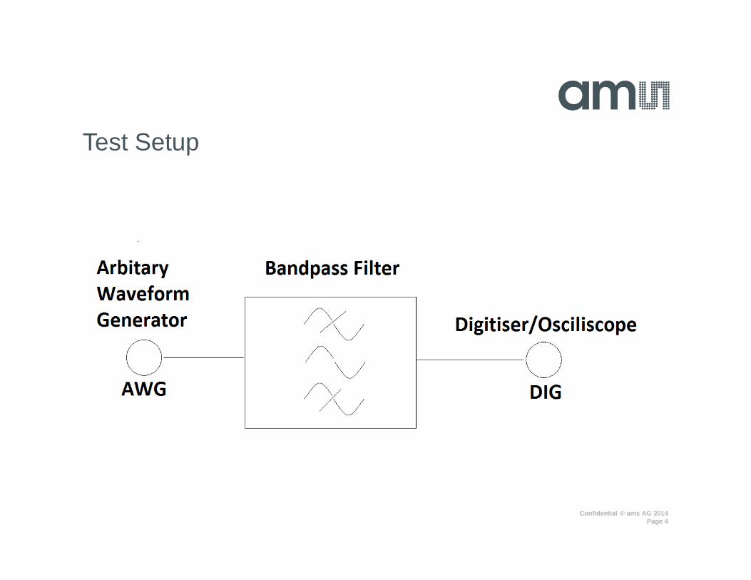
Test Setup

Confidential © ams AG 2014
Agenda
Problem StatementWhat is a chirpHow to make a discrete chirpFilter measurementsCorrelation and RepeatabilityWaveform FlexibilityTest Time SavingPhase and group delayExtension to BISTConclusion
Confidential © ams AG 2014Page 6
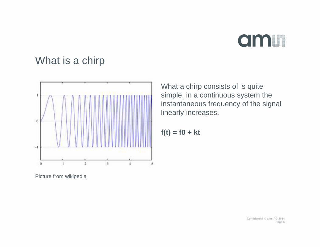
What a chirp consists of is quite simple, in a continuous system the instantaneous frequency of the signal linearly increases.
f(t) = f0 + kt
What is a chirp
Picture from wikipedia
Confidential © ams AG 2014Page 7
Why Chirp and not Multitone?
• Unfortunately for devices that have a very low input power sensitivity, a multitone can cause some issues.
• Max Tone Power = Max Input Power / NUM_FREQS
• i.e. tones in the noise floor
• intermodulation distortion product effects between individual tones
• i.e. IM3, IM5, IM7 etc

Confidential © ams AG 2014
Agenda
Problem StatementWhat is a chirpHow to make a discrete chirpFilter measurementsCorrelation and RepeatabilityWaveform FlexibilityTest Time SavingPhase and group delayExtension to BISTConclusion
Confidential © ams AG 2014Page 9
Chirp Signal Requirements
• What is the required accuracy of the measurement for the corner frequencies of the bandpass filter?
• What are the corner frequencies and bandwidth of the filter being measured?
• How do we make this waveform reusable?
• How do we do all this and not violate the max operating conditions of the AWG (Arbitrary Waveform Generator)?
Confidential © ams AG 2014Page 10
Chirp Signal Constraints
• Ensure that Max Sampling frequency is not exceeded− i.e. Sampling Frequency/Tone Frequency = NUM POINTS/BIN
NUMBER− Also Frequency Resolution = Sampling Frequency / NUM POINTS
• Ensure that Max memory depth is not exceeded− i.e. 16MB for LTX AWGHSB (High Speed AWG)
• Use a nomalised frequency so that the waveform is scalable i.e. a frequency resolution of 1
Confidential © ams AG 2014Page 11
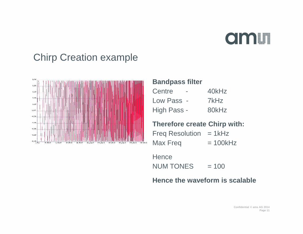
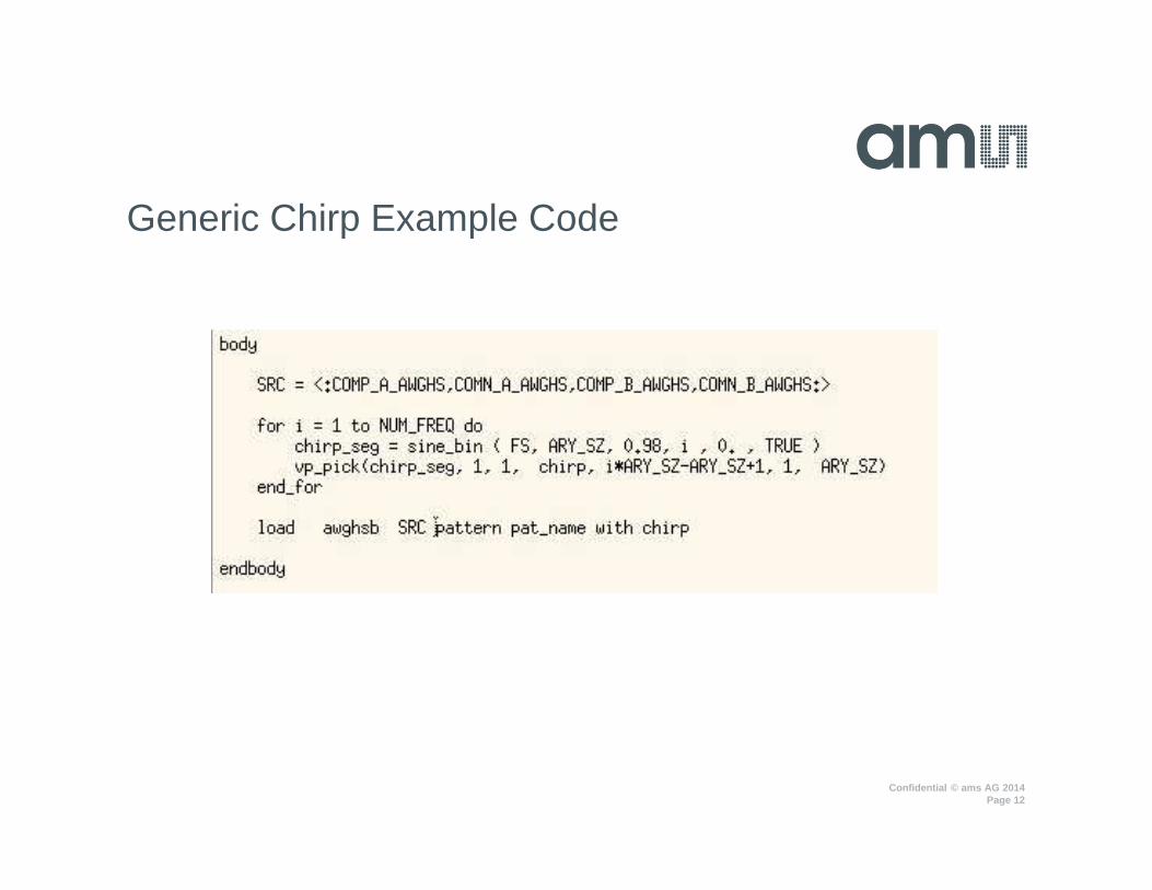
Bandpass filter Centre - 40kHzLow Pass - 7kHzHigh Pass - 80kHz
Therefore create Chirp with:Freq Resolution = 1kHzMax Freq = 100kHz
Hence NUM TONES = 100
Hence the waveform is scalable
Chirp Creation example
Confidential © ams AG 2014Page 12
Generic Chirp Example Code
Confidential © ams AG 2014Page 13
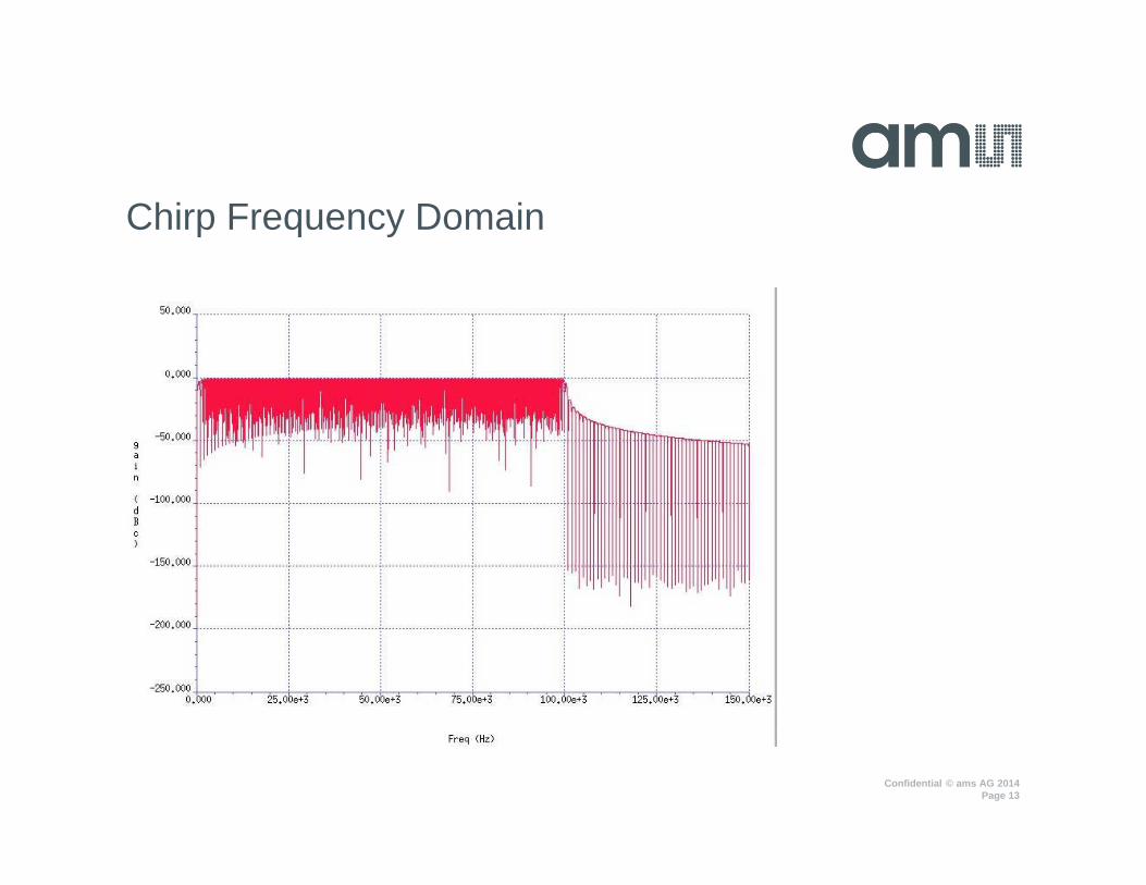
Chirp Frequency Domain

Confidential © ams AG 2014
Agenda
Problem StatementWhat is a chirpHow to make a discrete chirpFilter measurementsCorrelation and RepeatabilityWaveform FlexibilityTest Time SavingPhase and group delayExtension to BISTConclusion
Confidential © ams AG 2014Page 15
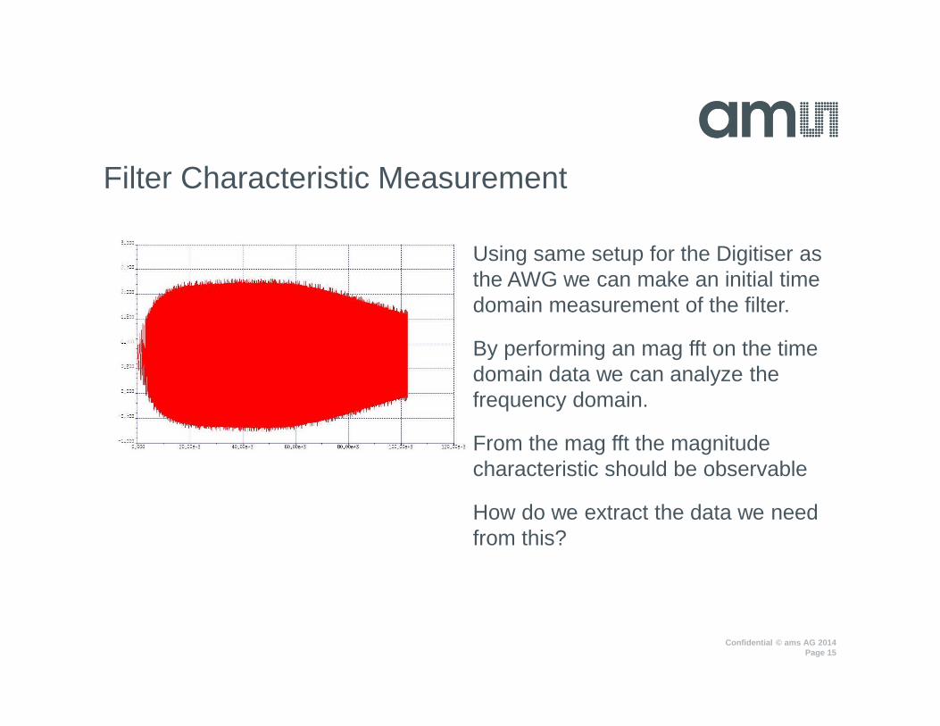
Using same setup for the Digitiser as the AWG we can make an initial time domain measurement of the filter.
By performing an mag fft on the time domain data we can analyze the frequency domain.
From the mag fft the magnitude characteristic should be observable
How do we extract the data we need from this?
Filter Characteristic Measurement
Confidential © ams AG 2014Page 16
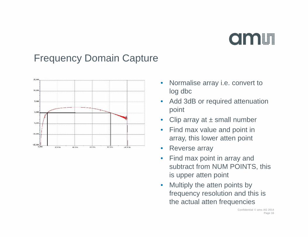
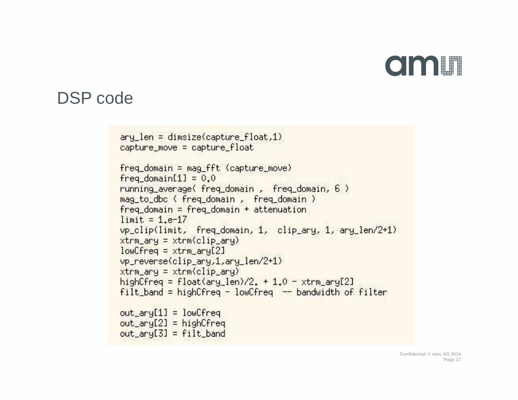
• Normalise array i.e. convert to log dbc
• Add 3dB or required attenuation point
• Clip array at ± small number• Find max value and point in
array, this lower atten point• Reverse array• Find max point in array and
subtract from NUM POINTS, this is upper atten point
• Multiply the atten points by frequency resolution and this is the actual atten frequencies
Frequency Domain Capture
Confidential © ams AG 2014Page 17
DSP code

Confidential © ams AG 2014
Agenda
Problem StatementWhat is a chirpHow to make a discrete chirpFilter measurementsCorrelation and RepeatabilityWaveform FlexibilityTest Time SavingPhase and group delayExtension to BISTConclusion
Confidential © ams AG 2014Page 19
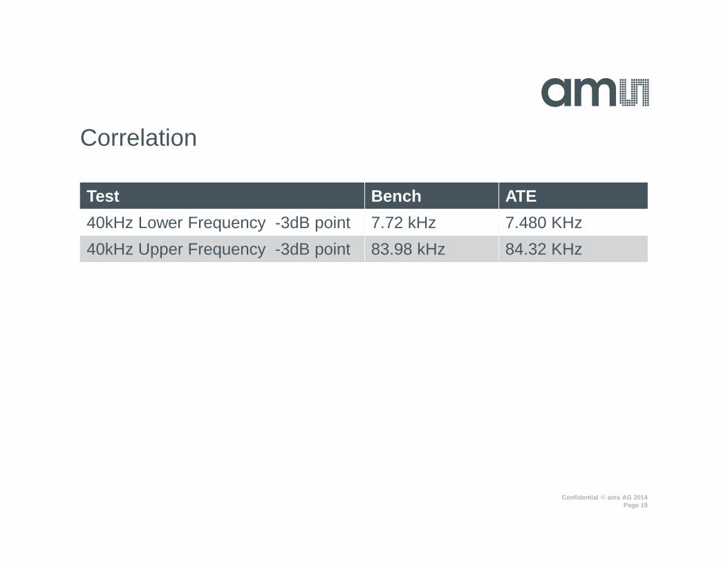
Correlation
Test Bench ATE
40kHz Lower Frequency -3dB point 7.72 kHz 7.480 KHz
40kHz Upper Frequency -3dB point 83.98 kHz 84.32 KHz

Confidential © ams AG 2014Page 20
Repeatability

Confidential © ams AG 2014
Agenda
Problem StatementWhat is a chirpHow to make a discrete chirpFilter measurementsCorrelation and RepeatabilityWaveform FlexibilityTest Time SavingPhase and group delayExtension to BISTConclusion

Confidential © ams AG 2014Page 22
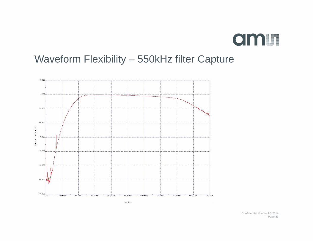
Waveform Flexibility
• Waveform has a 1kHz Frequency Resolution
• Waveform has 100 tones
• Hence waveform can be scaled easily hence saving more waveforms being generated if system allows
• Waveform can be scaled in frequency with a change to Sampling Frequency
• By multiplying sampling frequency by 10, the waveform now has a max frequency of 1MHz with a Frequency Resolution of 10kHz
Confidential © ams AG 2014Page 23
Waveform Flexibility – 550kHz filter Capture
Confidential © ams AG 2014Page 24
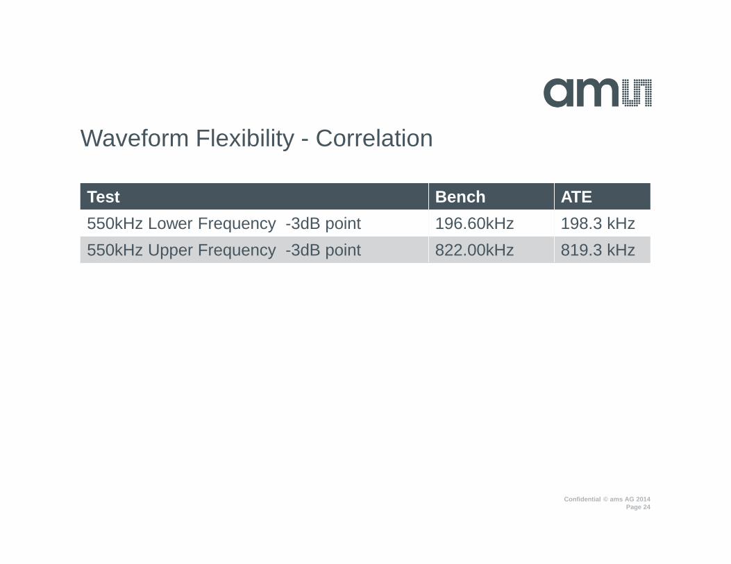
Waveform Flexibility - Correlation
Test Bench ATE
550kHz Lower Frequency -3dB point 196.60kHz 198.3 kHz
550kHz Upper Frequency -3dB point 822.00kHz 819.3 kHz
Confidential © ams AG 2014
Agenda
Problem StatementWhat is a chirpHow to make a discrete chirpFilter measurementsCorrelation and RepeatabilityWaveform FlexibilityTest Time SavingPhase and group delayExtension to BISTConclusion
Confidential © ams AG 2014Page 26
Test Time
• Original test program code using discrete frequencies and start/stop of AWG and DIG was 250ms, this was 5 frequencies not 100!
• Using chirp with no start stop is purely dependant on the UTP time of the source which is 100ms for this example.
• Difference is 150ms
• If UTP is faster i.e. faster Sampling Frequency the gain is more, why?− Start and stop and hardware stable time is fixed− Chirp test time is fixed by the UTP time, so 1 start/stop and 1
source/capture

Confidential © ams AG 2014
Agenda
Problem StatementWhat is a chirpHow to make a discrete chirpFilter measurementsCorrelation and RepeatabilityWaveform FlexibilityTest Time SavingPhase and group delayExtension to BISTConclusion
Confidential © ams AG 2014Page 28
Extension to Phase Information
• Waveform is not stopped between frequency segments− Due to this we have full phase information
• By doing an FFT instead of Mag FFT all phase information is available− i.e. Cosθand Sinθ
Confidential © ams AG 2014Page 29
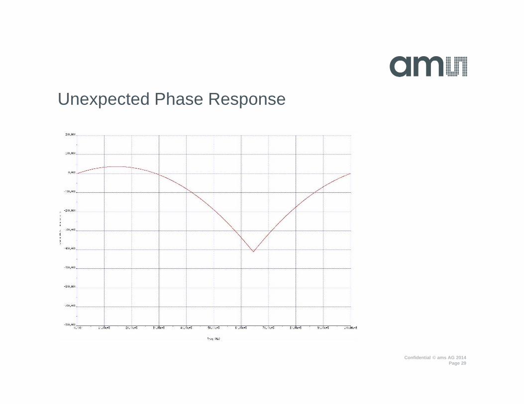
Unexpected Phase Response
Confidential © ams AG 2014Page 30
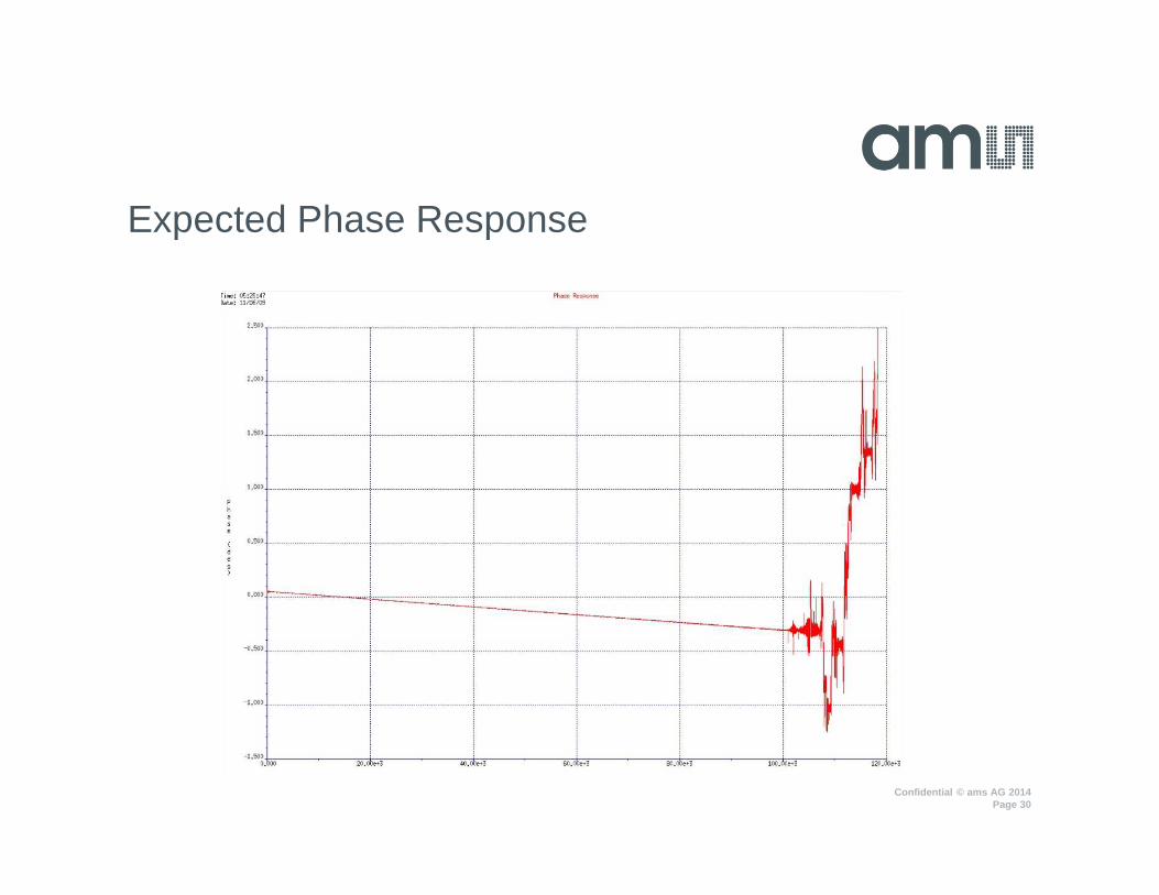
Expected Phase Response
Confidential © ams AG 2014Page 31
Phase Response
• Not expected phase response
• Due to frequency changing over time and hence causing a t^2 effect
• Once phase is differentiated the phase response looks correct
• However Phase Response result isn’t stable and doesn’t correlate
• Due to this group delay is a non starter
• Issue is due to the instantaneous phase of the AWG not being known
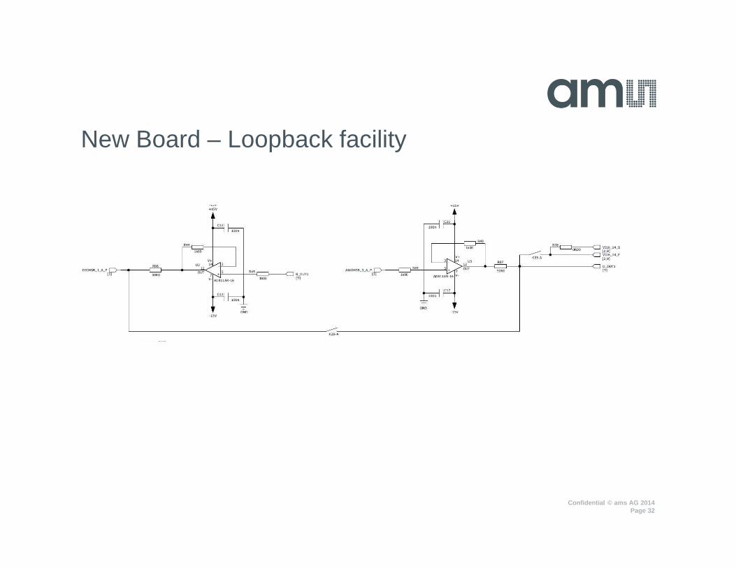
• Require a loopback onboard so as to do calibration during testing
Confidential © ams AG 2014Page 32
New Board – Loopback facility

Confidential © ams AG 2014
Agenda
Problem StatementWhat is a chirpHow to make a discrete chirpFilter measurementsCorrelation and RepeatabilityWaveform FlexibilityTest Time SavingPhase and group delayExtension to BISTConclusion
Confidential © ams AG 2014Page 34
BIST – Future work
• Add an on chip VCO with frequency range of the filter
• Ramp voltage on VCO input with cheap analogue resource
• Effect is an on-chip chirp generator

Confidential © ams AG 2014
Agenda
Problem StatementWhat is a chirpHow to make a discrete chirpFilter measurementsCorrelation and RepeatabilityWaveform FlexibilityTest Time SavingPhase and group delayExtension to BISTConclusion
Confidential © ams AG 2014Page 36
Conclusion
• By using a Chirp test time can be improved.
• Aid Design in initial ramp up and characterization.
• Possibility of Software IP and code reusability.
• With correct hardware design this can also be applied to Phase Response and Group Delay

Confidential © ams AG 2014
Thank you
Please visit our website www.ams.com