bs2 presentation
TRANSCRIPT

BUILDING SERVICES IISS15 COURTYARD, SUBANG JAYA
Fong Kah Yan (0322815)Phon Kit Poi (0328435) Lee Lin Hui (0322797)Lieu Xue Qi (0327523)
Hong Li Vian (0327007)Sew Yue Ling (0327032)
Nicole Thain (0325697)Jacquelyn Vanessa (0320021)

COURTYARD- Located in SS15
- High rise commercial building
- Developed by Titijaya Group

Mechanical Ventilation and Air Conditioning System

Mechanical Ventilation● The process where the air in a space is being removed
and replaced with fresh air ● Use of mechanical system such as powered fan and
air conditioning● Active design
Air Conditioning System● One of the mechanical ventilation systems ● Change the temperature of the air within a building ● Provide thermal comfort for the occupants● Unitary system, Package system and Centralized
system

Unitary system - Split AC● Commonly used in small and large offices, shops, rooms
➢ suitable for where only required to cooled certain time.● Two parts:
➢ Indoor – expansion coil, air filters and blower➢ Outdoor – compressor, condenser, expansion valve and cooling fan

How Split AC Unit Work?

Package System● Is the all-in-one cabinet - evaporator coil, condenser, compressor
● Refrigeration system is cooled by atmospheric air
● Commonly in restaurants, small halls, small commercial buildings
● Similar to split unit but it provides greater capacity and efficiency
● Condenser - Either air-cooled or water-cooled

Centralised air conditioning system
● Suitable for large building which comprised of several floors
● Commonly used in shopping mall, cinema, airport and hotel
● All the compressor, condenser, expansion valve and
evaporator are kept in a large plant room
● AHU room, Chiller room and Cooling tower
● Chilled air is supply to the building with a system of supply
and return ducts

HOW CENTRALISED AC SYSTEM WORKS?

Air Handling Unit (AHU) room
● Number of AHU room: 4● Location: 3 at ground level(G), one
at lower ground level(LG)● Consists of the supply duct for inlet
and outlet of air, blower, heating and cooling coil, filter compartment and ducting system.

● Blower serves to circulate the air
movement and control the airflow rate.
● Cooling coils are used to cool down
high temperature air.
● Heating coils serve to allow the low
temperature air to be heated up.
Internal part of AHU

Ducting system in AHU room
● Connected to the outlet and inlet
diffuser
● Supply air to or extract air from
the complex
● Allows the ideal temperature to
be achieved and maintained
● All the ducts are sealed, tested
for tightness and insulated

Filter panel
● helps clean the air● ensure that a dust free and
safe- inhaling air is supplied to the building
❖ CHWS (dark blue in colour) -chilled water supply
❖ CHWR (light blue in colour)-chilled water return
Pipes

Chiller room● 4 major components
-Condenser-Compressor-Expansion valve -Evaporator
● Exchange of heat between the condenser and evaporator via refrigerant
● Heated condenser water is then pumped up to the cooling tower for cooling
● Cooled condenser water is returned back to the chiller room
● The whole process is repeated

This is the chiller room located at level P4 (parking area) of ss15 Courtyard, there are a total of 3 chiller units. Two out of the three chiller units will take turn to operate every day to expand their service life span.

PipesCHWS (dark blue) - chilled water supply to AHU room
CHWR (light blue) - chilled water return from AHU room
CWS (light green) - condenser water supply to cooling tower
CWR (dark green)-condenser water return from cooling tower

Temperature sensor
❖ detect any changes in temperature of the liquid refrigerant
❖ leaving chilled water and entering condenser water shall be kept at 7oC and 30oC respectively.

Cooling Tower
● Normally located on top of a building● Condenser water is sprayed down
onto a water basin to increase the water surface area
● Fan on top to blow the water● Cooling effect is created when a
small amount of water is evaporated● The cooled condenser water is then
returned to the chiller unit

● Cooling tower in ss15 Courtyard● located at level 6 which is an open
air area
❖ Pipes that linked to chiller room❖ CWS (light green) - condenser water supply
from chiller room❖ CWR (dark green) - condenser water return
to chiller room
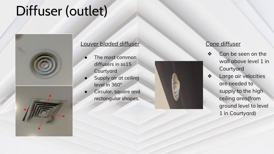
Diffuser (outlet)
Louver bladed diffuser
● The most common diffusers in ss15 Courtyard
● Supply air at ceiling level in 360°
● Circular, square and rectangular shapes.
Cone diffuser
❖ Can be seen on the wall above level 1 in Courtyard
❖ Large air velocities are needed to supply to the high ceiling area(from ground level to level 1 in Courtyard)

Linear diffuser
● Aesthetic purpose ● Air can also be delivered equally
around the perimeter of area outside the lift

Diffuser (inlet)
Return grilles
● Works in the opposite way to an outlet diffuser
● Extract air from the room for further conditioning.
● Some of the diffuser are hanging without any ceiling cover

Fire Protection System

● Active System● Passive System
● Active System● Passive System

Active Fire System
Active fire protection is the component of fire detection and prevention which reacts to action or motion. The role of active fire protection within the fire containment process is to detect, alert about, and seek to eliminate the fire hazard.

Sprinkler System❏ Providing adequate pressure
and flow rate ❏ If fire breaks out, the air
temperature rises and the sprinkler activates
❏ Sprinkler sprays water forcefully over the flames, extinguishing them

Fire Extinguisher❏ Used to extinguish or control
small fires, often in emergency situations
❏ The multipurpose dry chemical is effective on Class A, B, and C fires

Automatic CO2 System
❏ Carbon dioxide is an electrically non-conductive gas that is efficient as a fire suppression agent
❏ Once fire is detected, an alarm is sounded, the gas of Co2 is released

Wet/Dry Riser SystemWet Riser● Is a system where the
pipes are kept full of water for manual or automatic fire fighting operations
Dry Riser● Do not contain water
(charged with water when necessary)

Fire Alarm Detection System❏ To detect and warn
people through visual and audio appliance when smoke, fire are present
❏ It activated automatically from smoke detectors, and heat detectors or manual fire alarm devices

Smoke Detector
❏ Is a device that senses smoke, typically as an indicator of fire
❏ Issue a signal to a fire alarm control panel as part of a fire alarm system

Voice Communication System
❏ Provide response personnel with the ability to conduct orderly evacuation and notify building occupants
❏ Messages may be played to each floor, depending on the location of the fire

Hose Reel❏ Provide an accessible
and controlled supply of water to combat a potential fire risk.
❏ Length of a fully extended fire hose is 36 meters

Break Glass
❏ Enables personnel to raise the alarm by breaking the frangible element on the fascia

Fireman Switch❏ Is a specialized switch disconnector
❏ Used by firemen to turn off neon- lighting or other electrical equipment in case of fire

Passive Fire System
● An integral component of the structural fire protection and fire safety in the building
● Helps to reduce damage to the building
● Provides more evacuation time

Fire Door❏ Located at the fire escape exits
❏ Can delay the spread of fire, smoke
❏ Protect people in the building to escape

Exit Sign❏ Allows the
occupants to find the exit or safety zone
❏ Can be found at the ceiling above the doors.

Emergency Staircase❏ Provide clear
access to the road
❏ The ease of rescue process and fire fighting

Fire Evacuation Route❏ State the way to
escape
❏ Enhance the safe evacuation of all occupants

Bomba Lift❏ Allows commandeered by
the Fire Service
❏ Firefighters are able to access to whatever level they want

VERTICAL TRANSPORTATION SYSTEM

Vertical transportation system is a system that allow the user to access one floor to another floor.

ESCALATOR

A power-driven moving staircase that enable the passenger access from one
floor to another floor.

■ There are three different sizes of escalator in SS15 Courtyard.
Speed: about 0.45m/s Speed: about 0.50m/s Speed: about 0.47m/s
Step width: about 810mm Step width: about 1080mm Step width: about 977mm
FIGURE1 FIGURE 2 FIGURE 3

ARRANGEMENT OF ESCALATOR
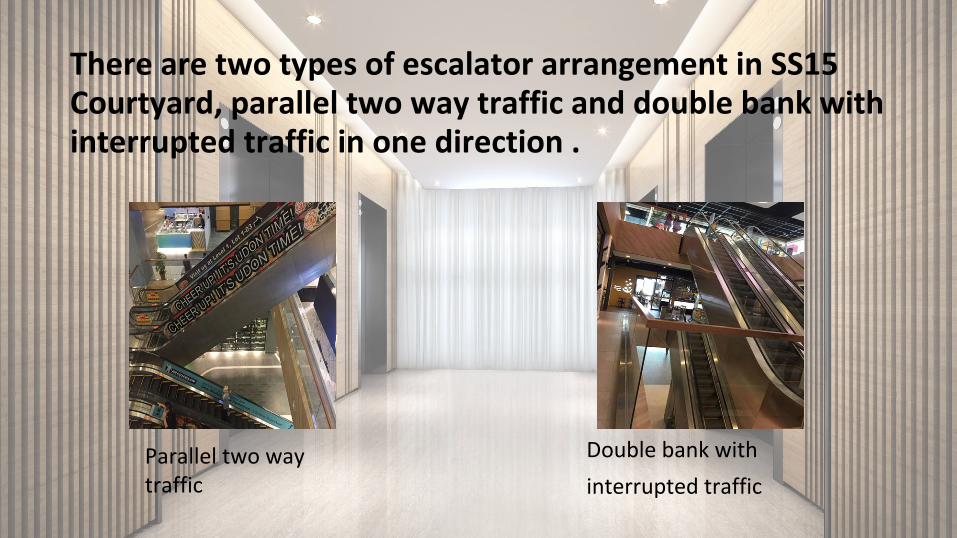
There are two types of escalator arrangement in SS15 Courtyard, parallel two way traffic and double bank with interrupted traffic in one direction .
Parallel two way traffic
Double bank with
interrupted traffic

LOCATION OF ESCALATOR

This escalator is located at basement. It allow the user to access from B1 (basement) to level LG (lower ground floor).

Figure 1 Figure 2 Both escalator is located at lower ground floor (LG). It allow the user to access from level LG (lower ground floor) to level G (ground floor).
Figure 1 escalator is located at the middle of the mall.
Figure 2 escalator is located at the side of the mall and also in front of the side entrance.

Figure 3 Figure 4
These two escalator is located at ground floor. It allow the user to access from level G(ground floor) to level 1 (first floor).
Figure 3 escalator is located at the middle of the mall and also in front of the main entrance.
Figure 4 escalator is located at the side of the mall.

COMPONENTS OF ESCALATOR

Components Functions1 Moving
Handrail A handhold that can provide stability for passenger
2 Truss Structure frame of escalator3 Steps An area that allow passenger to stand4 Landing
PlatformLocated at top and bottom of escalator. Top platform contains motor, bottom platform hold the step return idler sprocket.
5 Emergency Stop Button
Any accidents happened,It will stop the walkway immediately
6 Skirt Brush Prevent things to stuck in between the skirt guard and steps7 Demarcation
LineWarning security line

ADDITIONAL FEATURE IN LINE WITH GREEN TECHNOLOGY
Variable Voltage Variable Frequency (VVVF)
- save up to 60% of energy.
- When there is no passenger, the escalator and travelator will
stop to enter the saving mode.
-When there is people approaching, it will run immediately.

TRAVELATOR

A moving walkways to transport people in short distance or inclined distance between two floors of the building.

Types of travelator: 15 degrees inclined position Speed: about 0.45m/sStep width: about 1012mm

LOCATION OF TRAVELATOR

■ Connected from level LG(lower ground) to B1(basement).
■ Provide convenience for the Village Grocer customer who can travel the trolley from LG to B1.

COMPONENTS OF TRAVELATOR


ELEVATOR

■ Lift car capacity: 15 persons, 1025 KG
■ Duration: about 47s-60s from ground floor to P5 (parking 5)
■ Passenger transfer time: 2.0s in and out

■ Lift entrance width: about 1125mm
■ Door closing time: 3.2s
■ Type of door: single speed centre opening

ARRANGEMENT OF ELEVATOR

Six car arrangement
It consists of five passenger lifts and a firefighter lift.
Ground floor

Three car arrangement
It consists of two passenger lifts and a firefighter lift.
Lower ground floor
First floor

COMPONENTS OF ELEVATOR

Lift supervisoryFloor indicator
Emergency intercom Lift operating panel

Up and down button Ventilation hole
Hand railLift car

Components Functions
Control panel Control the operation of elevator
Overspeed governor To stop and hold the governor rope in case the elevator run exceeding the rated speed
Guard rail To guide the elevator travel uniformly
Counterweight It move at opposite direction with the lift car to balance the weight of car
Buffers To stop the lift car or counterweight during emergency
Wire ropes To hold the lift car
Traveling cable Used for power transmission for the elevator and communication between controller
Lift frame To support the lift car
Door operator To open and close the door
Landing door To prevent passenger or things falling into the hoistway

Electrical Supply System

● At the ground floor of SS15 Courtyard
● Incoming electrical power supplied
through an 11kV feeder from TNB
● Has high tension switchgears consists of
switching and protection devices that
controls the flow of electricity.
● The high voltage of electricity, 11kV will
be step down to several transformers
depending on the power demand to suit
the end user.
High Tension Room

● Vacuum Circuit Breaker (VCB) is used as
an on/off device to control the flow of
electricity
● The operation of the ON/OFF switch can
be controlled manually or automatically
when abnormal situations are detected
by the OCEF protection relay.
● When an abnormal situation is detected
by the OCEF relay, this protection relay
will automatically "trip" the VCB to
protect the end users and equipment
from damage.
3 phase, 11kV Control Panel
together with the OCEF relay in
blue colour
Vacuum Circuit Breaker
together with contact arms
on a withdrawable trolley

Transformer Room● 2 transformer rooms
● Smaller transformer - Grd Floor
● Bigger transformer - Basement
● Purpose: for them to step down 11kV
- to 415V.
● The stepped down current will then
be transferred to their own Main
Switch Board (MSB) that are located
in the Low Voltage Room.

The Transformer Panel Transformer switch when it is switched on

Readings on the transformer panel shows that it supplies 415V to the shops, residence
and offices in the building

Dry Transformer with protective metal cages (Basement)

Smaller Transformer (Ground floor)

Low Tension Room ● Next to the Transformer Room.
● The output from the secondary side of
transformer, which is at low voltage is
connected to low tension room with
cables.
● The equipment in low tension room uses
air circuit breaker.
● 3 Main Switch Boards distribute
electricity to the landlord, tenants and
chiller, these panels are the main power
switches of the entire building.

● Receives the low voltage electricity from the transformer and
supply it to multiple units of Distribution Boards (DB) located
at every floor of the building through the Riser Room
● Contains a lot of air-insulated Moulded Case Circuit Breakers
(MCCB) and its associated control and protection circuitry.
Main Switch Board (MSB)
Air Insulated MCCBs Low voltage OCEF relay

● Also known as panelboard or breaker
panel.
● To divide the electrical power feed into
subsidiary circuits while providing a
protective fuse or circuit breaker for each
circuit.
● Offers protection to users and equipment
from electrical shock or fire resulting
from ground fault.
● The electricity from the DB is then further
delivered to a smaller version of MCCB ,
Miniature Circuit Boards (MCB) and
Earth Leakage Circuit Board (ELCB).
Distribution Board

Riser Room
● Every floor of SS15 Courtyard.
● Consist of Distribution Board (DB) -
from the Main Switch Board (MSB) -
to every electric appliances each floor
● Consist of an Essential Distribution
Board (ESB) - receive electricity from
generator during emergency.

Electrical Meter Distribution Board Wiring

Generator Set Room
● 1st Floor in the building
● Backup electrical supply source
when there is an electrical
breakdown - TNB station
● Generate electricity either
automatically or manually -
diesel oil after it detects that
there is no electricity

● SS15 Courtyard - manually
● The generator’s power will be pumped and supplied by the MSB to make it run
● Diesel will then be added into the tank to run the motor inside the generator
● The electricity generated will transfer to EMSB in the Low Voltage Room, then to the ESB in Riser Room.
● Generate electricity - until the power supply has been regained, then manually switched off
● Enough for the lightings which are directly connected such as the lifts, lobby or toilets
● Offices, no - due to the shortage of electric supply.

Main Switch Board that supplies the electricity to the generator

Ventilation System
● Switched on - generate electricity when the motor
inside starts to run
● Cause to produce heat - ventilation needed
● Prevent overheating
● Flexible bellows attached to the back of the
generator - let the hot air out through a louvered
panel in order for the heat to not be trapped.

Diesel Tank● Photo shows - maximum area allowed;
dangerous
● Purpose: Store the diesel to run the generator
when it is switched on
● Why? - Battery has much lower specific energy
than the fuel like gasoline
● Diesel fuel is required to work out the generator
while still using battery to operate
● When the diesel fuel passes through the motor -
combustion occur.
● Dynamo will generate electric field and current
supplied - LV room, distributing areas.

Carbon Dioxide Tanks
● Safety purpose
● In case of fire
● A carbon dioxide pilot will pull its trigger to
conduct those tanks to work to put out the fire
during emergencies
● Available in all electrical supply rooms

PROBLEMS

Problems of mechanical ventilation and air-conditioning
Cooling tower
● Growth of algae and bacteria like Legionella
● Corrosion - expose to air and water.
● Fouling - deposition of suspended material
● Increase the hardness of water and water
consumption
● Increase the energy consumption
● Reduce the efficiency of the entire system

RECOMMENDATIONS & SOLUTIONS ON IMPROVING AIR CONDITIONING SYSTEM
Cooling Tower Cleaning and Maintenance
1. Regular maintenance● Remove contaminants and keep it as clean as possible● Do inspection regularly to ensure it functions properly
2. Continuous monitoring● Purchase equipment and software to supervise the cooling-system
water● To check the water quality and system efficiency

3. Systematic filtration
● Side stream filtration● Draw out trapped contaminants
in the water before they can accumulate in the basin
● Filtered water returns back to the chiller room or cooling tower
● All the problems (growth of algae and biological bacteria, fouling and corrosion) can be solve directly or indirectly

Problems of fire protection system
Problem 1
❏ Most of the fire door cannot
close automatically

Problems of fire protection system
Problem 2❏ Advertisement boards are
placed in front of the fire
door

RECOMMENDATIONS and SOLUTIONS ON IMPROVING FIRE PROTECTION SYSTEM
❏ Apply a electronic magnetic door catch/holder
❏ Allow a fire door to be held open electro-magnetically
❏ The magnet is released and the door closer will close the fire door when event of fire
❏ To help limit the spread of fire

RECOMMENDATIONS and SOLUTIONS ON IMPROVING FIRE PROTECTION SYSTEM
❏ Instruct the mall security guards to take a
proactive action

THANK YOU!