beta lasermike system benefits 7 lasermike system benefits 11 beta lasermike system solutions...
TRANSCRIPT


7Beta LaserMike System Benefits
11Beta LaserMike System Solutions
DataPro:Process Control & Data Management Systems
UltraScan: Wall , Eccentricity, Diameter & Ovality Measurement Systems
AccuScan: Diameter & Ovality Measurement Systems
PowerMike Continuous Vulcanization Measurement System
Beta LaserMike Corporate Contact Information 32
Contents
Beta LaserMike Products
16
20
30
13
CenterScan: Non-Contact Eccentricity Measurement System
26
3
LN Detector: Fault Detection Systems
Spark Testers: Fault Detection Systems
22
25
LaserSpeed: Non-Contact Length & Speed Measurement Systems
28
Preheaters: Wire Preheating Systems
BenchMike: Off-Line Diameter & Ovality Measurement Systems
24
31


6
Introduction
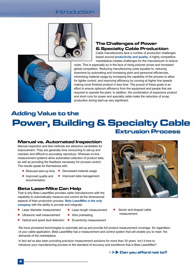
The Challenges of Power & Specialty Cable ProductionCable manufacturers face a number of production challenges based around productivity and quality. A highly competitive marketplace creates challenges for the manufacturer to reduce
costs. This is especially so in the face of rising polymer prices and increased global competition. Reducing manufacturing costs equates to; reducing downtime by automating and increasing plant and personnel efficiencies, minimising material usage by increasing the capability of the process to allow for tighter control, and improving efficiency by running at higher line speeds making more finished product in less time. The pursuit of these goals is an effort to ensure optimum efficiency from the equipment and people that are required to operate the plant. In addition, the combination of expensive product and short runs for power and specialty cable make the reduction of scrap production during start-up very significant.
Adding Value to the
Manual vs. Automated InspectionManual inspection and test methods are attractive candidates forimprovement. They are generally time consuming to set-up andmaintain and difficult to accurately reproduce. Whereas on-linemeasurement systems allow automated collection of product data,as well as providing the feedback necessary for process control. The results speak for themselves with: Reduced start-up time Improved quality and
documentation
Extrusion Process
Decreased material usage Improved data management
Beta LaserMike Can HelpThat is why Beta LaserMike provides cable manufacturers with the capability to automatically measure and control all the dimensional aspects of their production process. Beta LaserMike is the only company with the ability to provide and integrate: Laser diameter measurement Ultrasonic wall measurement Optical and spark fault detection
We have pioneered technologies to automate set-up and provide full product measurement coverage. So regardless of your cable application, Beta LaserMike has a measurement and control system that will enable you to meet the demands of the marketplace.
In fact we’ve also been providing precision measurement solutions for more than 30 years. Isn’t it time tointroduce your manufacturing process to the standard of accuracy and excellence that is Beta LaserMike?
Can you afford not to?
Power, Building & Specialty Cable
Laser length measurement Wire preheating Eccentricity measurement
Sector and shaped cable measurement

Reduce Start-Up Time......with Die CenteringThe start-up period of a cable extrusion line is often the cause of scrapped material and the most significant loss of production time. Without an on-line gauging and control system that shows the true cross-sectional profile of the cable’s eccentricity, the operator’s only tool to quickly center the die is his or her own skill and experience, and perhaps a bit of luck.
Savings from Reduced Startup Time
DataPro 5000 Cross Section Display
Start Up Problem: DataPro Solution:
The result of a die centering adjustment is unknown until the cable reaches the end of the line.
Multiple iterations of die centering adjustments are often required increasing startup time. The number of iterations of die centering adjustments is very dependent on operator experience.
Reduces the dependence of start-up time on the experience of the operator by allowing more iterations of die centering adjustments to take place in the same amount of time.
Provides on-line cross-section display of cable eccentricity, which greatly reduces the delay between the time of a die centering adjustment and when the operator sees the result of that adjustment.
1.
2.
To calculate the mass of scrap material that can be saved during startup each year:
Material Savings = π [(OD/2) 2 - (Core /2) 2] * [Current Startup Time – New Startup Time] * [Material Density] * [Avg Line Speed] * [Start-ups Per Year]
Multiply the material savings by the cost of material (per unit of weight) to find cost savings. For total savings, add the saved amont of core product as well.
7
System Benefits
Note: Be sure to use consistent units of measure in calculations
Average Diameter 50 mm (2 in.) Wall Thickness 2.5 mm (0.1 in.) Insulation Area 191.441 mm2 (20.30631in.2)Material Density 1215kg/m3 (76lb/ft3) Startup Without Control 30 min. (30 min.) Startup With Control 15 min. (15 min.)
Startups Annually 200 Average Line Speed 60 m/min (200 ft/min) Material Weight Savings 41868 kg (96997 lb.) Material Cost 1Euro/kg ($0.5/lb.) Annual Cost Savings 41,868 Euro ($48,498)
Example:

8
System Benefits
Example:
...with Closed-Loop ControlMost cable extrusion operators run the line at sizes that are well above the minimum specifications in order to ensure that they do not create scrap product. This ensures that the extrusion line is at a maximum of up-time, but also creates a scenario where all finished product includes a high amount of material “give away”.
How DataPro decreases material usage and give away: Closed loop feedback control continuously monitors
cable dimensions and automatically controls the line to target sizes
Auto-setpointing automatically lowers the target size (setpoint) toward the minimum specification, while monitoring standard deviation to allow enough “safety margin” that ensures the size does not go below specification
Eccentricity improvement of the cable allows the average wall to run closer to the minimum specification without one side of the wall going below specification.
Savings from Decreased Material Usage and Give AwayTo calculate the mass of material that can be saved each year by decreasing the amount of extra material that is “given away”:
Material Savings = {π [(OD1/2) 2 - (Core /2) 2] * [Density] * [Length]} - {π [(OD2/2) 2 - (Core /2) 2] * [Density] * [Length]}
Where OD1 is the OD of the cable before the wall is reduced, and OD2 is the OD of the cable after the wall is reduced. “Density” is the density of the material and “Length” is the length of cable produced per year.
Note: Be sure to use consistent units of measure in calculations.
DataPro 5000 Material Usage Display
Decrease Material Usage & “Give Away”...
DataPro control features: Control of line speed or extruder RPM Cross-section display of cable allows for quick
die centering
Control ouptuts include direct analog, relay contacts,or stepper motor drive
Control algorithms include PI and Correct & Delay
1. Any wall reduction is out-of-tolerance due to poor eccentricity
2. Eccentricity improvement allows more wall reduction
3. Average wall reduction saves material usage
Average Diameter 50mm (2 in.) Wall Reduction 50 micron (2 mils) Area Saved 3.925 mm2 (0.00628 in.2)Material Density 1215 kg/m3 (76 lb./ft3) Annual Production 9 million/m (30 million ft)
Density*Length 10935 kg/mm2 (15833333 lb./inch2)Material Weight Savings 42920 kg (99434 lb.) Material Cost 1 Euro/kg ($0.5/lb.) Annual Cost Savings 42,920Euro ($49,717)

Beta LaserMike DataPro 3000 - Summary Report 04-Jun-03 12:34 Library 5 ABC Co. N2345
Sample Separation: 5.0 M Subgroup Size: 5 Batch Size: 0 _________________________________________________________ OD
Upper Specification Limit: 7.345 mm Nominal: 7.335 mm Lower Specification Limit: 7.325 mm
Subgroups: 30 X bar: 7.320 mm X double bar: 7.317 mm R: 0.005 mm R bar: 0.030 mm
Average: 7.317 mm Maximum: 7.341 mm Minimum: 6.599 mm Standard Deviation: 0.065 mm CpK: -0.43 CP: 0.52
Improve & Document Product Quality......with Closed -Loop Control and SPCClosed-loop control has significant benefits in material cost savings, but it also improves product quality. In addition, when coupled with the collection and analysis of SPC data, it truly maximizes the benefit of the measurements taken by Beta LaserMike systems. The DataPro controller receives measurement information on a continuous basis from the gauging systems and will take samples of those measurements on a periodic basis defined by the user. Once those samples of measurement data are taken, the many benefits of SPC data analysis can be utilized:
Improve product quality by controlling the process and using SPC data to identify and improve on process trends
Improve the efficiency and effectiveness of your quality documentation and show your customers and ISO auditors that you can prove your quality claims
Improve preventative maintenance efforts by monitoring standard deviation of the process over time and looking for potential degradation of the process capability
Using the CP and CpK Process Capability Indexes
The CP index compares the total specification range versus the full distribution of product sizes. It is calculated as: CP= USL-LSL where USL and LSL are the Upper and Lower Specification Limits and σ is the Standard Deviation.
CP answers the question:“Am I capable of making good product?”
CpK answers the question:“Did I make good product?”The CpK indicates whether the distribution of product sizes is within the desired specifications. It is calculated as CpK= smaller of USL-Avg and Avg-LSL .
CP < 1.0(Process Not Capable of Making 100% Good Product)
1.0 < CP < 1.33(Process is Capable, but Requires Monitoring)
CP > 1.33(Process is Capable of Making 100% Good Product)
CpK < 0(Avg Size is Outside Specification Limits)
0 < CpK < 1.33(Avg Size is in Specification, but some of Product is Out of Spec)
CpK > 1.33(All Sizes are Within Specification Limits)
6σ 3σ 3σ
On-Screen and Printed Reports
9
System Benefits

10
System Benefits
...with Real-time Trend ChartsReal-time trend charts allow operators to monitor product sizes graphically. The user may customize the trend charts to show any desired data trending versus time, length, or data points. Screens may be formatted to show one, two, or four trend charts per page. Trend charts are available only with DataPro 5000.
Improve Data Management...
...with Networking & IntegrationDataPro controllers are designed for easy and flexible integration with other devices and systems at the cable extrusion line, from alarm lights and printers to the actual extruder or take up.
...with Printed ReportsPrinted reports are generated to document product quality. Reports can be triggered manually by the operator or automatically at the end of a run or after a certain amount of product length. With the DataPro 5000, the user customizes the reports and may save multiple formats. These reports can be saved electronically or printed to hard copy.
...with Data LoggingData logging allows managers and engineers to record and analyze process data without having to stand and observe the extrusion line. Data can be logged to a local drive at the DataPro 5000 or to a network drive away from the plant floor. Logging of data can occur manually or automatically, based on a pre-defined period of time or length, or at the crossing of a line speed.
...with AlarmingAlarming allows notification to operators when product or process problems occur. DataPro controllers are connected to alarm lights or horns for immediate alarm notification at the extrusion line. DataPro 5000 also has an alarm history log that shows product tolerance errors, process problems, or any other “events” defined by the user.
*DataPro 5000 Datalog File. Started 20-Mar-03 15:15:01*DataLog_Line35_20Mar03*Time Avg Wall Min Wall15:15:31 1.683 1.65115:16:01 1.684 1.65515:16:31 1.693 1.66115:17:01 1.700 1.67115:17:31 1.692 1.67115:18:01 1.699 1.66815:18:31 1.701 1.67515:19:01 1.689 1.65215:19:31 1.678 1.64015:20:01 1.687 1.64315:20:31 1.686 1.648
Beta LaserMike DataPro 3000 - Summary Report 04-Jun-03 12:34 Library 5 ABC Co. N2345 Sample Separation: 5.0 M Subgroup Size: 5 Batch Size: _____________________________________________________ ID Upper Specification Limit: 6.178 mm Nominal: 6.168 mm Lower Specification Limit: 6.158 mm
Subgroups: 30 X bar: 6.174 mm X double bar: 6.178 mm R: 0.002 mm R bar: 0.015 mm

*Preheater, LN Detector, Spark Tester, and/or LaserSpeed can be addedto any configuration for solutions of preheating, fault detection or length/speed measurement.
Solutions for Solid Primary Cable
Gauge Inputs
Solution* AccuScan UltraScan Wall Config. # Diameter C -01 Hot/Cold Diameter; Shrink Compensation B/C -02 Core/Cold Diameter; Wall Calculation A/C -10 Core/Hot/Cold Diameter; A/B/C -12 Shrink Compensation; Wall Calculation Diameter; Wall & Eccentricity C X -22
*Preheater, CenterScan, LN Detector, Spark Tester, and/or LaserSpeed can be added to any configuration for solutions of preheating, eccentricity, fault detection or length/speed measurement.
Gauge Inputs
Solution* AccuScan Config. # Diameter C -01 Hot/Cold Diameter; Shrink Compensation B/C -02 Core/Cold Diameter; Wall Calculation A/C -10 Core/Hot/Cold Diameter; Shrink Compensation; Wall Calculation A/B/C -12
11
System Solutions
PreheaterWire Preheating
AccuScanDiameter & Ovality
AccuScanDiameter & Ovality
UltraScanWall & Eccentricity
AccuScanDiameter & Ovality
Fault Detection
LN Detector Spark
Tester
LaserSpeedLength & Speed
DataProProcess Control
PreheaterWire Preheating
AccuScanDiameter & Ovality
AccuScanDiameter & Ovality
AccuScan Diameter & Ovality
Fault Detection
(A) (B) (C)
(A) (B) (C)
CenterScanEccentricity
LN Detector Spark
Tester
LaserSpeedLength & Speed
DataPro
Process Control
Solutions for Foamed Primary Cable
System Solutions
12
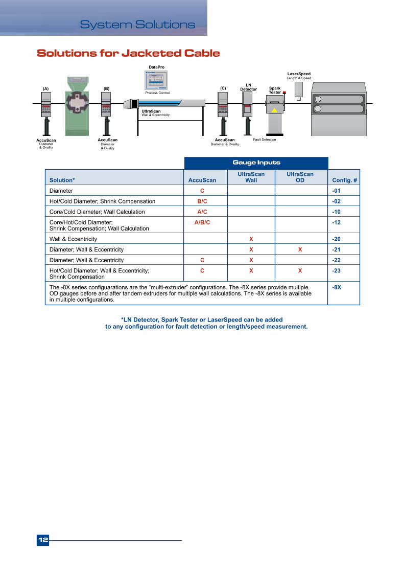
Solutions for Jacketed Cable
Gauge Inputs
UltraScan UltraScan Solution* AccuScan Wall OD Config. #
Diameter C -01
Hot/Cold Diameter; Shrink Compensation B/C -02
Core/Cold Diameter; Wall Calculation A/C -10
Core/Hot/Cold Diameter; A/B/C -12 Shrink Compensation; Wall Calculation
Wall & Eccentricity X -20
Diameter; Wall & Eccentricity X X -21
Diameter; Wall & Eccentricity C X -22
Hot/Cold Diameter; Wall & Eccentricity; C X X -23 Shrink Compensation
The -8X series configuarations are the “multi-extruder” configurations. The -8X series provide multiple -8X OD gauges before and after tandem extruders for multiple wall calculations. The -8X series is available in multiple configurations.
AccuScanDiameter & Ovality
AccuScanDiameter & Ovality
UltraScanWall & Eccentricity
AccuScanDiameter & Ovality
Fault Detection
LN Detector Spark
Tester
LaserSpeedLength & Speed
DataPro
(A) (B) (C)Process Control
*LN Detector, Spark Tester or LaserSpeed can be added to any configuration for fault detection or length/speed measurement.

13
DataPro
Beta LaserMike’s DataPro controller series, when coupled with dimensional measurement instrumentation and a versatile set of I/O capabilities, enable you to produce superior quality cable by providing all the information and control capability you need to keep your production process running smoothly. DataPro systems aid and improve the cable manufacturing process at every step, from the start-up period to the production period to the final quality checks.
Process Control & Data Management Systems
DataPro Controller Models
Feature DataPro 1000 DataPro 3100 DataPro 5000
Display Vacuum fluorescent 5.7” TFT touch screen 15” TFT touch screen
Gauge support AccuScan UltraScan UltraScan SRL AccuScan AccuScan CenterScan LaserSpeed LN Detector Spark Testers LaserSpeed Preheaters CapScan
Max gauges 1 2 Not limited
Cross-section display No Yes (1 layer only) Yes (multi-layer possible)
Control loops 1 1 2
Auto setpoint control No No Yes
SPC 1 channel 2 channels 15” 8 channels
Trend charts No No 15” 5 channels
Printed reports Yes (fixed) Yes (fixed) Yes (custom)
Data logging No Yes (via Ethernet) 15” 20 channels
Serial ports RS-232 RS-232 (2) RS-232 & USB
Ethernet port Configuration & Configuration & Data I/O Yes (10/100 Base T) XY Data Output
Alarming Yes Yes Yes
Product recipes No Yes (100) Yes (not limited)
Security No 3 levels 10 levels
Remote display output No No VGA with optional touchscreen
I/O Digital, analog, Digital, analog, relay contacts, Digital, analog, relay contacts, serial & Ethernet serial, USB & Ethernet serial, parallel, Ethernet & VGA
14
DataPro
All controller configurations are available with DataPro 5000
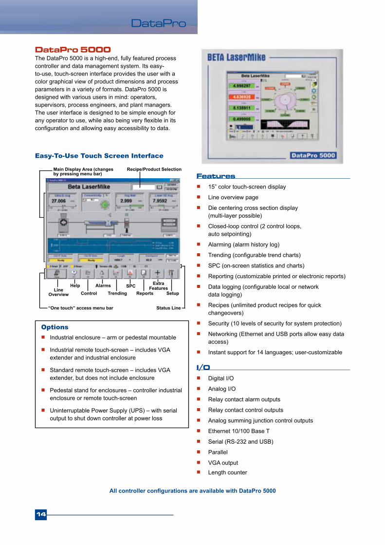
DataPro 5000The DataPro 5000 is a high-end, fully featured process controller and data management system. Its easy- to-use, touch-screen interface provides the user with a color graphical view of product dimensions and process parameters in a variety of formats. DataPro 5000 is designed with various users in mind: operators, supervisors, process engineers, and plant managers. The user interface is designed to be simple enough for any operator to use, while also being very flexible in its configuration and allowing easy accessibility to data.
Features 15” color touch-screen display
Line overview page
Die centering cross section display (multi-layer possible)
Closed-loop control (2 control loops, auto setpointing)
Alarming (alarm history log)
Trending (configurable trend charts)
SPC (on-screen statistics and charts)
Reporting (customizable printed or electronic reports)
Data logging (configurable local or network data logging)
Recipes (unlimited product recipes for quick changeovers)
Security (10 levels of security for system protection)
Networking (Ethernet and USB ports allow easy data access)
Instant support for 14 languages; user-customizable
I/O Digital I/O
Analog I/O
Relay contact alarm outputs
Relay contact control outputs
Analog summing junction control outputs
Ethernet 10/100 Base T
Serial (RS-232 and USB)
Parallel
VGA output Length counter
Easy-To-Use Touch Screen Interface
Options Industrial enclosure – arm or pedestal mountable
Industrial remote touch-screen – includes VGA extender and industrial enclosure
Standard remote touch-screen – includes VGA extender, but does not include enclosure
Pedestal stand for enclosures – controller industrial enclosure or remote touch-screen
Uninterruptable Power Supply (UPS) – with serial output to shut down controller at power loss
Recipe/Product Selection
Line Overview
HelpControl
AlarmsTrending
SPCReports
ExtraFeatures
Setup
Status Line
Main Display Area (changes by pressing menu bar)
“One touch” access menu bar
15
DataPro
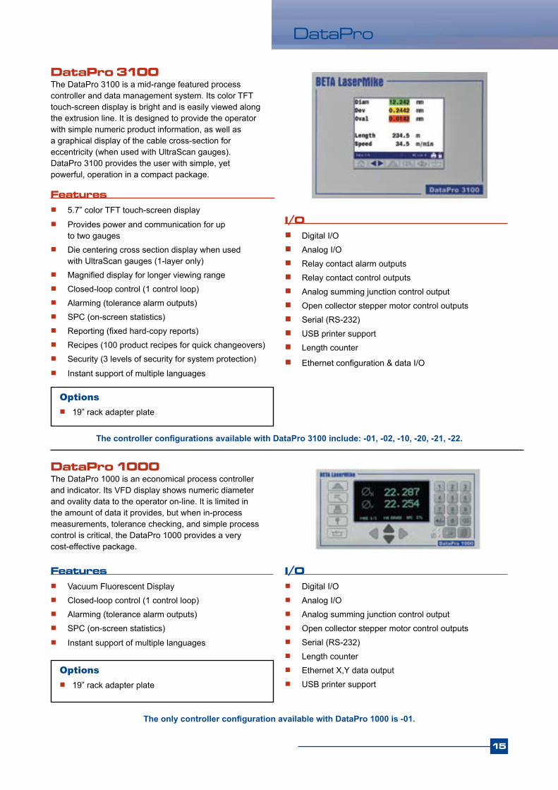
DataPro 3100The DataPro 3100 is a mid-range featured process controller and data management system. Its color TFT touch-screen display is bright and is easily viewed along the extrusion line. It is designed to provide the operator with simple numeric product information, as well as a graphical display of the cable cross-section for eccentricity (when used with UltraScan gauges). DataPro 3100 provides the user with simple, yet powerful, operation in a compact package.
Options 19” rack adapter plate
DataPro 1000The DataPro 1000 is an economical process controller and indicator. Its VFD display shows numeric diameter and ovality data to the operator on-line. It is limited in the amount of data it provides, but when in-process measurements, tolerance checking, and simple process control is critical, the DataPro 1000 provides a very cost-effective package.
Features Vacuum Fluorescent Display Closed-loop control (1 control loop) Alarming (tolerance alarm outputs) SPC (on-screen statistics) Instant support of multiple languages
I/O Digital I/O Analog I/O Analog summing junction control output Open collector stepper motor control outputs Serial (RS-232) Length counter Ethernet X,Y data output USB printer support
Options 19” rack adapter plate
The only controller configuration available with DataPro 1000 is -01.
Features 5.7” color TFT touch-screen display Provides power and communication for up
to two gauges Die centering cross section display when used
with UltraScan gauges (1-layer only) Magnified display for longer viewing range Closed-loop control (1 control loop) Alarming (tolerance alarm outputs) SPC (on-screen statistics) Reporting (fixed hard-copy reports) Recipes (100 product recipes for quick changeovers) Security (3 levels of security for system protection) Instant support of multiple languages
The controller configurations available with DataPro 3100 include: -01, -02, -10, -20, -21, -22.
I/O Digital I/O Analog I/O Relay contact alarm outputs Relay contact control outputs Analog summing junction control output Open collector stepper motor control outputs Serial (RS-232) USB printer support Length counter
Ethernet configuration & data I/O
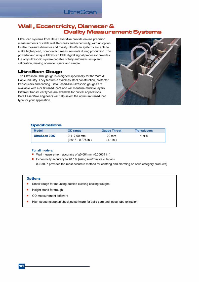
Wall , Eccentricity, Diameter & Ovality Measurement SystemsUltraScan systems from Beta LaserMike provide on-line precision measurements of cable wall thickness and eccentricity, with an option to also measure diameter and ovality. UltraScan systems are able to make high-speed, non-contact measurements during production. The powerful and unique UltraScan DSP digital signal processor provides the only ultrasonic system capable of fully automatic setup and calibration, making operation quick and simple.
UltraScan
Specifications
UltraScan GaugeThe Ultrascan 3007 gauge is designed specifically for the Wire & Cable industry. They feature a stainless steel construction, protected transducers and cabling. Beta LaserMike ultrasonic gauges are available with 4 or 8 transducers and will measure multiple layers. Different transducer types are available for critical applications. Beta LaserMike engineers will help select the optimum transducer type for your application.
Model OD range Gauge Throat TransducersUltraScan 3007 0.4- 7.00 mm 29 mm 4 or 8 (0.016 - 0.275 in.) (1.1 in.)
Options Small trough for mounting outside existing cooling troughs
Height stand for trough
OD measurement software
High-speed tolerance checking software for solid core and loose tube extrusion
For all models: Wall measurement accuracy of ±0.001mm (0.00004 in.) Eccentricity accuracy to ±0.1% (using min/max calculation) (US3007 provides the most accurate method for centring and alarming on solid category products)
16

17
UltraScan
Ultrasonic Wall & Eccentricity Measurement Principle
UltraScan DSP sends an electrical drive pulse and the transducers convert that energy into an ultrasonic sound wave.
Multi-Point Diameter & OvalityUsing multiple transducers provides full measurement of the product. This allows the calculation of ovality and the determination of the minimum and maximum diameter.
OD = Dg – (G1 + G2) where Dg is the distance between transducers
and G1 and G2 are the gaps between the transducers and the outer wall of the cable
Echoes are sent back to the ultrasonic transducers from the walls of the pipe and the transducers convert that energy into an electrical waveform.*
**UltraScan gauges include a water temperature sensor to increase accuracy of gap measurements.
*With multi-layer cables, an echo occurs at each layer and therefore each layer can be measured individually.
Multi-Point Wall & EccentricityThe use of multiple transducers (or reversing the transducers), provides full measurement of the product. This allows the calculation of eccentricity in addition to the display of minimum and maximum wall thickness. This information can be used in control to maximise material saving by centering the die and by controlling to minimum wall.
Ultrasonic Diameter & Ovality Measurement Principle
The UltraScan DSP calculates the wall thickness as: Wall = ( t * s) / 2
t = time between echoes s = speed of sound through the material
To measure cable diameter, the distance between the two transducers is determined at calibration and the gap** between each transducer and the outer wall of the cable is measured by UltraScan DSP. The diameter of the cable is determined with these three pieces of information.

Unique Ultrasonic Technology
Snap TechnologySo Simple, it’s always being usedAll ultrasonic measurement systems require some form of setup of the ultrasonic waveform. The measurement system must know what are the proper echoes and positions in the waveform to trigger on and measure from, and the user must set this up.
But the UltraScan DSP, with its unique and powerful patented Snap Technology, is the world’s only ultrasonic system that is capable of completely setting up its own ultrasonic waveforms instantly and automatically. The intelligence of Snap Technology provides fully automatic ultrasonic measurement with:
Auto-search Auto-setup Auto-tracking
Highest achievable ultrasonic accuracySince each ultrasonic transducer is set up individually, other ultrasonic systems have the potential to introduce error in the measurements due to the human error created by manual setup. And when conditions of the product or the process change, the fixed manual setup does not adapt the signal processing with the changes. But when the measurements are set up automatically with Snap Technology, it ensures that the setup is the same across all transducers. And when conditions of the product or the process change, the auto setup instantly adapts the signal processing with the changes. This continuous and automatic setup of all transducers ensures maximum consistency across each transducer, thus providing higher accuracy of average wall and concentricity measurements.
18
UltraScan
Auto-Search: UltraScan DSP finds the echoes and sets a “window” around them.
Auto-Setup: UltraScan DSP interprets the ultrasonic waveform and identifies the proper echoes.
Auto-Tracking: UltraScan DSP “locks” onto the proper echoes and tracks them as the product moves.
The 4 on-line wall measurements show some inconsistency (caused by differences in the
manual waveform setup of the 4 transducers).
The 4 on-line wall measurements all follow the wall changes precisely the same, due to Snap Technology’s auto-
matic setup and tracking software.
Temperature CompensationThe Ultrascan system contains a temperature compensation algorithm for applications where due to proximity to the extruder, there is a temperature gradient through the product. As the line speed is increased or decreased, the product temperature will change. The material speed of sound (the ultrasonic calibration) value is adjusted to more accurately calculate the product wall thickness from the echo time measured for the wall. The Ultrascan uses a mathematical model to derive the new calibration value as the line speed changes. The model uses current water temperature, initial product temperature (at the “quench” point), product material type, and one calibration point as inputs. If the initial product temperature at the quench point is not known, it can be derived by calibrating at two different line speeds.

High-Speed Tolerance CheckingDetection and notification of short-term wall variations
Unique Ultrasonic Technology
19
UltraScan
1. UltraScan detects error
2. Message sent to DataPro 5000
3.DataPro signals a marking device downstream (after length delay)
Standard tolerance checking compares averaged wall values against tolerance limits
High speed tolerance checking compares individual scans against tolerance limitsDataPro 5000
Ultrasonic systems are often implemented in cable extrusion lines to monitor for and correct gradual changes in the wall thick-ness. Short-term variations in wall thickness are often missed when the ultrasonic system is averaging data and monitoring for periodic changes. But UltraScan systems are capable of taking approximately 2,000 wall measurements per second, dependent on thickness, and have an advanced feature for High-Speed Tolerance Checking. The UltraScan DSP checks each scan of each transducer and compares the measurement against wall tolerances. This high-speed checking of tolerances is designed to catch short-term wall variation on each individual layer of the cable.
Once a high-speed tolerance error is found, the UltraScan DSP sends a signal to the DataPro 5000 controller to indicate that an error has occurred. The DataPro 5000 can then send a signal to a device downstream that will mark or cut out the area of the product that is out-of-tolerance. A length delay is implemented by the DataPro 5000 after the error message is received, so that the mark or cut matches with the position of the error.
Record keeping of short-term wall variationsThe UltraScan DSP sends details of each error to the DataPro 5000, including: which transducers detected the error
max and min wall size during error
length of error
which layer or layers contain error
*Each error message sent is logged to a report on the DataPro 5000 screen
AccuScan
20
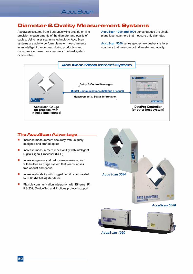
AccuScan 5080
AccuScan systems from Beta LaserMike provide on-line precision measurements of the diameter and ovality of cables. Using laser scanning technology, AccuScan systems are able to perform diameter measurements in an intelligent gauge head during production and communicate those measurements to a host system or controller.
Diameter & Ovality Measurement Systems
The AccuScan Advantage Increase measurement accuracy with uniquely
designed and crafted optics
Increase measurement repeatability with intelligent Digital Signal Processor (DSP)
Increase up-time and reduce maintenance cost with built-in air purge system that keeps lenses free of dust and debris
Increase durability with rugged construction sealed to IP 65 (NEMA 4) standards
Flexible communication integration with Ethernet IP, RS-232, DeviceNet, and Profibus protocol support
AccuScan 1000 and 4000 series gauges are single- plane laser scanners that measure only diameter.
AccuScan 5000 series gauges are dual-plane laser scanners that measure both diameter and ovality.
AccuScan Measurement System
AccuScan 5040
AccuScan 1050

AccuScan
21
Laser Scanning Measurement PrincipleIn 1972, the founders of Beta LaserMike introduced the world’s first laser scanning micrometer (the “LaserMike”). AccuScan gauges employ this laser scanning measurement principle, which uses a low-power helium-neon laser that is scanned at high speed through a measurement window and across the cable.
When the laser first scans across to the receiver, the light hits the photocell and the voltage rises. The voltage drops when the light is blocked by the pipe and rises again when the light reaches the photocell. The change in time ( t) that the light is blocked by the pipe is proportional to the cable’s outside diameter.
AccuScan ModelsEach AccuScan gauge has built-in signal processing and intelligence and supports communication in Ethernet IP, RS-232, DeviceNet, and Profibus protocols. Air purge systems are available to keep the windows clean of dust and debris.
Model OD Range Gate Size AccuracyAccuScan 5012 0.1–12 mm 16 mm ±0.0005 mm1
(0.004–0.47 in.) (0.63 in.) (±0.000020 in.)AccuScan 5025 0.2–25 mm 52 mm ±0.001 mm1
(0.008–1.00 in.) (2.05 in.) (±0.000040 in.)AccuScan 5040 0.2–40 mm 52 mm ±0.001 mm1
(0.008–1.50 in.) (2.05 in.) (±0.000040 in.)AccuScan 5080 1.27–80 mm 108 mm ±0.002 mm2
(0.050–3.15 in.) (4.25 in.) (±0.000080 in.)AccuScan 3175* 10–175 mm 200 mm ±0.02 mm3
(0.39–6.89 in.) (7.87 in.) (±0.00080 in.)
1 ±0.02% of product size 2 ±0.01% of product size 3 ±0.1% of product size (at center of gate)*AccuScan 3175 uses camera CCD technology. All other AccuScan 1000 and 5000 series gauges use laser scanning technology.
Options Height stand (normal upright or at 45 degrees)
Roller guides
Air cleaner filtering unit
In-head, high-speed flaw detection software
STAC logic software (measures max/min OD of corrugated products)
AS5000 Features Standard 2400 measurements per second Standard per facet calibration for highest achievable
accuracy Integrated air purge for extended operation Highly flexible communication including: Ethernet IP,
DeviceNet, Profibus, CanOpen & RS232Enhanced ultra-bright display Rugged, robust IP65 rated housing Use stand-alone or as part of a full line solution
AccuScan 3000/5000 Series
AccuScan 1000 /4000 Series
Now with Ethernet IP!
Model OD Range Gate Size AccuracyAccuScan 1050 0.35–50 mm 66 mm ±0.003 mm (0.014–2.00 in.) (2.6 in.) (±0.00010 in.)AccuScan 1100 1.27–100 mm 117 mm ±0.006 mm (0.050–4.00 in.) (4.6 in.) (±0.00025 in.)AccuScan 1140 0.75–140 mm 152 mm ±0.020 mm (0.030–5.50 in.) (6.0 in.) (±0.00080 in.)AccuScan 1190 1.25–190 mm 218 mm ±0.025 mm (0.050–7.50 in.) (8.6 in.) (±0.00100 in.)AccuScan 4012 0.1––12 mm 16 mm ±0.0005 mm1
(0.004–0.47 in.) (0.63 in.) (±0.000020 in.)NEW!

22
LN Detector
Fault Detection SystemsThe LN Detector series of dual- and three-axis products are designed for detection of short-term faults in the diameter of the cable (lumps or neckdowns). LN Detectors are self-contained instruments with fast response circuitry and solid-state infrared light sources that allow instant detection of changes in the cable diameter. The signal processing and intelligence is built into the gauge head and outputs can be taken straight from the LN Detector that trigger alarms or marking devices when faults are detected.
Infrared Fault Detection Principle
Normal State Lump Detected Neckdown Detected
The infrared light source and optics inside the gauge head create a continuous “curtain” of light across the cable. The product blocks a certain amount of the light that registers a voltage level at the receiver. A short variation in the diameter changes the amount of light at the receiver. When the change in sensitivity to light passes a user-defined threshold, a fault is triggered. (Single-axis detection is shown to clearly illustrate the measurement principle.)
NEW!3-Axis
Model LN1025–D (-DL) LN1040–D (-DL) LN3015 Number of axes 2 2 3 Product diameter 0.040-25 mm 0.040-40 mm 0.020-15 mm (0.002-1.0 in.) (0.002-1.6 in.) (0.0008-0.6 in.)Gate size 50 mm (2.0 in.) 50 mm (2.0 in.) 18 mm (0.71 in.) Sensitivity range 0.05 - 2 mm 0.100 - 10 mm 0.02 - 2 mm (0.0020 - 0.08 in.) (0.0040 - 0.40 in.) (0.0008 - 0.08 in.)Minimum flaw length 0.80 mm (0.03 in.) 0.80 mm (0.03 in.) 0.5 mm (0.02 in.) Maximum Line Speed 1500 m/min 1500 m/min 3000 m/min (4,920 ft/min.) (4,920 ft/min.) (9,842 ft/min.)Interfaces Standard RS-232 RS-232 RS-232, DeviceNet, Ethernet Optional Ethernet/IP, Profibus, Profinet Power requirements 100-240 VAC, 100-240 VAC, 24 VDC, 1.0 A 50-60 Hz, 0.5 A 50-60 Hz, 0.5ADimensions 360 x 380 x 80 mm 360 x 380 x 80 mm 245 x 255 x 82 mm (14.2 x 15.0 x 3.1 in.) (14.2 x 15.0 x 3.1 in.) (9.6 x 10.0 x 3.2 in.)
Specifications

23
LN Detector
NEW!3-Axis Lump & Neckdown Detector The three-axis LN3015 is the newest solution in fault detection from Beta LaserMike. It provides more precise detection of short-term faults in the product diameter at higher line speeds than the two-axis systems. The LN3015 uses three optical axes spaced at 60-degree intervals to deliver a higher degree of coverage around the product’s circumference to instantly detect sudden changes in the surface. It can accommodate product diameters up to 15 mm.
Three-Axis LN3015 Advantages More built-in communications for easy integration –
accept a range of inputs including length encoder, tachometer, line start/stop, clear faults, and reel change. The LN3015 can be easily connected to a host PC or PLC using RS232, Ethernet IP, DeviceNet, Profibus, and Profinet.
Capture, track, and report critical data – capture important flaw process information and effectively report on height, length, number, and location.
Monitor gauge performance with built-in diagnostics – ensure proper signal strength for each axis, maximize uptime with clean optics, and keep a close eye on other gauge performance.
Visualize fault and gauge statuses – alert operators on lump and neckdown conditions or when the gauge is operational via color-coded status indicators.
Synchronize with reel changes – accept signals from reel changers to clear system data and initialize for the next reel.
Performs in toughest environments – benefit from long, reliable service with ruggedized and environmentally sealed metal housing designed to IP65 standards. Engineered to minimize light and dust contamination.
User-friendly operator interface – no need to mount an external display. The LN3015 is equipped with an ultra-bright, integrated display and operator interface for easy access to gauge functions and to view messages.
The LN 3015 three-axis detector provides a higher degree of coverage around the product’s circumference compared to the LN1025/LN1040 two-axis gauges. The LN3015 precisely detects the smallest of flaws at higher production line speeds.
3-Axis
2-Axis

24
Preheaters
Preheaters from Beta LaserMike provide uniform, in-process wire heating to eliminate insulation voids in primary cables. When a wire is preheated for only fractions of a second by a low frequency (50/60 Hz) heat cycle, the heat is unevenly applied to the wire, resulting in hot and cold spots. When high frequency preheating is used, more heat cycles are applied to the wire, ensuring more consistent heating all along the length of the wire. For this reason, all Beta LaserMike Preheaters use high frequency heating.
Safety features include wire break detection, current overload sensors, and a wire path that is concealed behind an electrically locked door
An interface for an external temperature controller is provided on all models, allowing compensation for low speed applications and varying input temperatures
All Preheater components are carefully designed to ensure that power losses are minimized and that all input power is used to heat the wire
Wire Preheating Systems
Preheater Models
Max wire temperature is 370º F (190º C) for MCS 120 and 280. Max wire temperature is 750º F (400º C) for MCS 190.
Pulley sleeve is contact/insulating for MCS 120 and 280. Pulley sleeve is ceramic for MCS 190.
Model OD range Max line speed Pulley size Power output Max loop voltage
MCS 120L0817 0.28 – 1.4 mm 2500 m/min. 2 x 120 mm 8 kVA 17 V (0.01– 0.055 in.) (8200 ft/min.) (2 x 4.7 in.) 29 – 15 AWG
MCS 280L1640 0.45 – 2.8 mm 2500 m/min. 2 x 280 mm 16 kVA 40 V (0.02– 0.11 in.) (8200 ft/min.) (2 x 11 in.) 25 – 9 AWG
MCS 190L1640 0.37 – 1.4 mm 2500 m/min. 2 x 190 & 2 x 120 mm 16 kVA 40 V (0.015 – 0.055 in.) (8200 ft/min.) (2 x 7.5 in. & 2 x 4.7 in.) 27 – 15 AWG

25
SparkTesters
Fault Detection Systems
Options SI900 or SI900-RC spark tester indicator module PIB1000 Profibus interface module
Spark Testers from Beta LaserMike provide on-line detection of faults in cable insulation such as voids and pin holes. All Spark Testers are height-adjustable and floor mounted for easy placement in line. Standard models are available for a variety of applications, including high-frequency models for higher line speeds. Spark Testers can be controlled via the SI900 spark tester indicator with standard RS-232 communication and built-in I/O, or via a Profibus interface module. Meets virtually every international spark testing standard Multiple safety features include EHT warning lamps,
interlock safety switches, ozone extraction ports, and current limiting circuits
Grounding chains on the input and output remove any excess charge on the cable
Easy threading at startup with a lid design that lifts bead chain electrodes away from cable
Unique bead chain design lets you replace individual strands instead of entire assembly
Model OD range Test voltage Electrode length Max line speed Max electrode current* S1525 1 – 25 mm 1 – 15 kV 330 mm 400 m/min. 10/4.5 mA (0.04 – 1.0 in.) (13 in.) (1300 ft/min.)S2550 1 – 50 mm 1 – 25 kV 330 mm 400 m/min. 10/4.5 mA (0.04 – 2.0 in.) (13 in.) (1300 ft/min.)S25100 1 – 100 mm 1 – 25 kV 200 mm 240 m/min. 10/4.5 mA (0.04 – 4.0 in.) (7.87 in.) (790 ft/min.) S25150 1 – 150 mm 1 – 25 kV 200 mm 240 m/min. 10/4.5 mA (0.04 – 6.0 in.) (7.87 in.) (790 ft/min.)
Standard Models
Model OD range Test voltage Electrode length Max line speed Max electrode current* HFS0610 0.1 – 10 mm 1 – 6 kV 180 mm 3000 m/min. 6/25 mA (0.004 – 0.4 in.) (7.1 in.) (9840 ft/min.) HFS0915 0.1 – 15 mm 1 – 9 kV 135 mm 2250 m/min. 6/25 mA (0.004 – 0.6 in.) (5.3 in.) (7380 ft/min.) HFS1220 0.1 – 20 mm 1 – 12 kV 90 mm 1000 m/min. 6/25 mA (0.004 – 0.8 in.) (3.5 in.) (3300 ft/min.)
High Frequency Models
*Resistive/Capacitive

26
CenterScan
Wire and cable manufacturers now have better quality controlWhen the core of insulated wire and cable moves off-center, your product quality suffers. And with the increasingly tighter tolerances demanded by users, unchecked wire or cable eccentricity can leave you with reels of unusable product. There’s now a proven solution to help you dramatically control and improve the quality of your product while reducing material consumption and scrap, increasing productivity, and maximizing your profits.
The CenterScan measurement system from Beta LaserMike accurately and reliably monitors the diameter of insulated wire and cable and eccentricity of conductors during extrusion and insulation processes. This intelligent gauge never touches your product and can determine eccentricity and diameter measurements on products from 0.1 – 10 mm (0.004 – .40 in). Also, CenterScan’s high-speed measurement capabilities enable you to run higher line speeds and produce more finished wire and cable in less time while maintaining the highest level of product quality.
Non-contact gauge
Multi-function: eccentricity, diameter and flaw detection
Ultra accurate, low-drift measurements
High-speed signal processing for precise measurements on stranded products
Compact design for wider range of gauge installation on production line
Robust electronics with superior noise immunity allows closer placement to line devices
Factory calibrated for fast, easy setup and simple recalibration
Accurate product positioning with minimal alignment
Rugged construction for reliable operation under the harshest conditions
Flexible communication for easy integration, data management
Optional ultra-bright integrated display and operator interface for ease of use
Non-Contact Eccentricity Measurement System
CenterScan is compact, easy to calibrate and
simple to use!
CenterScan Measurement System Includes: Inductor Driver
Gauge head with high-frequencey laser scanning technology and sensing coils
Optional controller
Optical and inductive measurement technology detects the center of your
wire with the highest accuracyCenterScan combines optical and inductive technology to precisely measure the insulation diameter and conductor eccentricity. The optical measurement system is based on Beta LaserMike’s legendary AccuScan technology. This high-frequency laser scanning engine measures the outer diameter and position of insulation in two axes. The orienta-tion of the conductor is measured inductively. A driver induces an alternating current into the conductor to produce a magnetic field along the wire. This field is detected by four sets of highly sensitive coils strategically located around the wire to determine the precise location of the conductor.
ApplicationsThe CenterScan gauge is designed to effectively measure all round, single conductor wire and cable with solid or stranded conductors. Wire and cable applications include:
LAN RF Coaxial Mini coaxial Telephone Automotive Installation And more...
CenterScan
27
CenterScan
Measurement range 0.1 – 10 mm (0.004 – 0.40 in)
Gate Size 14 mm (0.55 in)
Resolution 0.00001 mm (0.0000004 in)
Accuracy ±0.0005 mm1 (±0.000020 in)
Measurement speed 1200 per axis per second
Dimensions (overall) 463 x 279 x 202 mm (18.25 x 11 x 7.96 in)
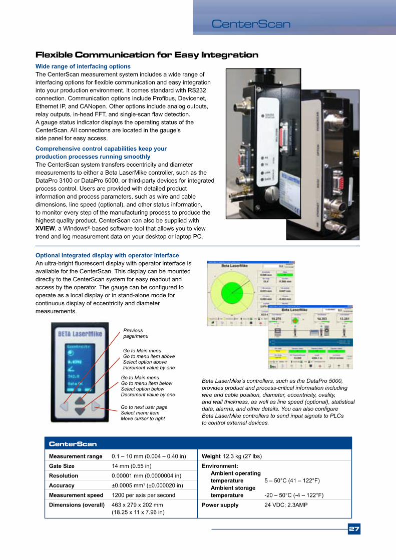
Wide range of interfacing optionsThe CenterScan measurement system includes a wide range of interfacing options for flexible communication and easy integration into your production environment. It comes standard with RS232 connection. Communication options include Profibus, Devicenet, Ethernet IP, and CANopen. Other options include analog outputs, relay outputs, in-head FFT, and single-scan flaw detection. A gauge status indicator displays the operating status of the CenterScan. All connections are located in the gauge’s side panel for easy access.
Comprehensive control capabilities keep your production processes running smoothlyThe CenterScan system transfers eccentricity and diameter measurements to either a Beta LaserMike controller, such as the DataPro 3100 or DataPro 5000, or third-party devices for integrated process control. Users are provided with detailed product information and process parameters, such as wire and cable dimensions, line speed (optional), and other status information, to monitor every step of the manufacturing process to produce the highest quality product. CenterScan can also be supplied with XVIEW, a Windows®-based software tool that allows you to view trend and log measurement data on your desktop or laptop PC.
Flexible Communication for Easy Integration
Weight 12.3 kg (27 lbs)
Environment: Ambient operating temperature 5 – 50°C (41 – 122°F) Ambient storage temperature -20 – 50°C (-4 – 122°F)
Power supply 24 VDC; 2.3AMP
Beta LaserMike’s controllers, such as the DataPro 5000, provides product and process-critical information including wire and cable position, diameter, eccentricity, ovality, and wall thickness, as well as line speed (optional), statistical data, alarms, and other details. You can also configure Beta LaserMike controllers to send input signals to PLCs to control external devices.
Optional integrated display with operator interfaceAn ultra-bright fluorescent display with operator interface is available for the CenterScan. This display can be mounted directly to the CenterScan system for easy readout and access by the operator. The gauge can be configured to operate as a local display or in stand-alone mode for continuous display of eccentricity and diameter measurements.
Previous page/menu
Go to next user pageSelect menu itemMove cursor to right
Go to Main menuGo to menu item aboveSelect option aboveIncrement value by one
Go to Main menuGo to menu item belowSelect option below Decrement value by one
28
LaserSpeed
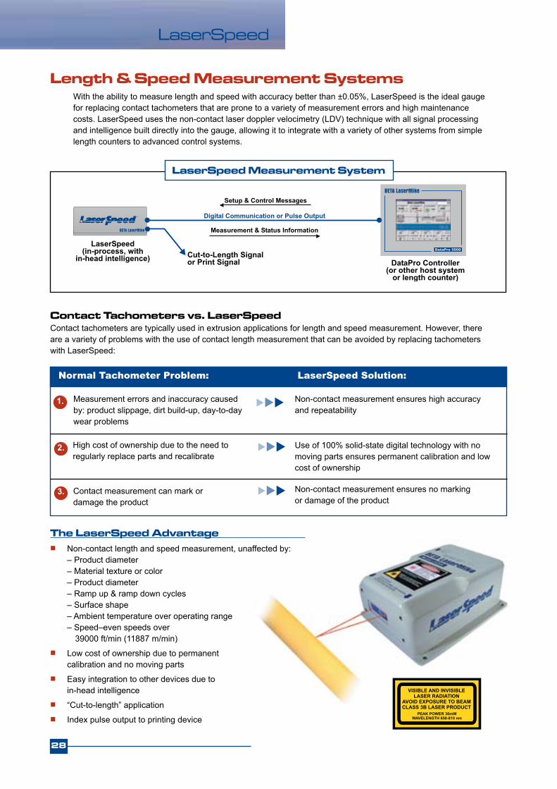
With the ability to measure length and speed with accuracy better than ±0.05%, LaserSpeed is the ideal gauge for replacing contact tachometers that are prone to a variety of measurement errors and high maintenance costs. LaserSpeed uses the non-contact laser doppler velocimetry (LDV) technique with all signal processing and intelligence built directly into the gauge, allowing it to integrate with a variety of other systems from simple length counters to advanced control systems.
Length & Speed Measurement Systems
The LaserSpeed Advantage Non-contact length and speed measurement, unaffected by:
– Product diameter – Material texture or color – Product diameter – Ramp up & ramp down cycles – Surface shape – Ambient temperature over operating range – Speed–even speeds over 39000 ft/min (11887 m/min)
Low cost of ownership due to permanent calibration and no moving parts
Easy integration to other devices due to in-head intelligence
“Cut-to-length” application Index pulse output to printing device
LaserSpeed Measurement System
Contact tachometers are typically used in extrusion applications for length and speed measurement. However, there are a variety of problems with the use of contact length measurement that can be avoided by replacing tachometers with LaserSpeed:
Contact Tachometers vs. LaserSpeed
Normal Tachometer Problem: LaserSpeed Solution:
Measurement errors and inaccuracy caused by: product slippage, dirt build-up, day-to-day wear problems
High cost of ownership due to the need to regularly replace parts and recalibrate
Use of 100% solid-state digital technology with no moving parts ensures permanent calibration and low cost of ownership
Non-contact measurement ensures high accuracy and repeatability
1.
2.
Non-contact measurement ensures no marking or damage of the product
3. Contact measurement can mark or damage the product
29
LS4000Model Speed Range Standoff Distance Depth of Field
LS4000-301 0.2 – 1,700 m/min (0.7 – 5,500 ft/min) 100 mm (4 in.) 15 mm (0.6 in.)
LS4000-303 0.4 – 4,000 m/min (1.3 – 13,100 ft/min) 300 mm (12 in.) 35 mm (1.4 in.)
LS4000-306 0.8 – 8,000 m/min (2.6 – 26,200 ft/min) 600 mm (24 in.) 50 mm (2.0 in.)
LS4000-310 1.0 – 12,000 m/min (3.2 – 39,400 ft/min) 1000 mm (39.4 in.) 75 mm (3.0 in.)
LS9000 With Zero Speed & Automatic Direction Detection!Model Speed Range Standoff Distance Depth of Field
LS9000-303 0..±4000 m/min (0..±13100 ft/min) 300 mm (12 in.) 35 mm (1.4 in.)
LS9000-306 0..±8000 m/min (0..±26200 ft/min) 600 mm (24 in.) 50 mm (2.0 in.)
LS9000-310 0..±12000 m/min (0..±39400 ft/min) 1000 mm (39.4 in.) 100 mm (3.0 in.)
Options Height Stand
Air Wipe
Quick Change Window
Analog Output Converter: Converts 0 – 2V speed output to other voltage or current ranges
LaserSpeed Models
Each model has the same high accuracy (<±0.05%) and repeatability (<±0.02%) and comes in an IP 67 rated industrial enclosure
The following I/O is included as standard with each model: Speed output: RS-232
0 – 2 volts (user selectable full scale) Length output: Isolated quadrature pulse output (user selectable resolution)
Isolated quadrature pulse output (fixed at 1000 pulses/ft)
Index pulse output for printer or cutter (selectable pulse rate per unit of measure)
Status output: RS-232 or analog voltage (0 – 1V) Inputs: Direction, Measurement Hold, Shutter Control, Laser Interlock
NEW!
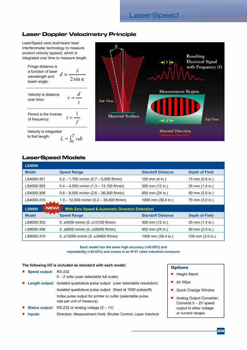
Laser Doppler Velocimetry PrincipleLaserSpeed uses dual-beam laser interferometer technology to measure product velocity (speed), which is integrated over time to measure length.
Fringe distance is a function of laser wavelength and beam angle:
Velocity is distance over time:
Period is the inverse of frequency:
Velocity is integrated to find length:
LaserSpeed

PowerMike
Accurate, Non-Contact Measurements of Power CableThe Beta LaserMike PowerMike Scanners are powerful, in-line diameter gauges designed specifically for in-tube cable diameter measurement on steam and nitrogen cure CV extrusion lines. Power cable is measured while inside the telescopic tube. By measuring your power cable close to the extruder, the PowerMike allows you to make quick adjustments to cable diameter, thereby minimizing scrap and excess material usage while improving overall product quality.
The PowerMike also features self-compensating circuitry to maintain measurement accuracy even in harsh, dirty environments. This unique design prevents moisture, steam bursts, smoke, changes in cable position, and residue on the gauge windows and/or the cable from affecting diameter measurements. The high output, solid state laser diode in this scanner penetrates the harsh environment inside the telescopic tube to ensure continuous measurements. The gauge’s collimated laser beam enhances accuracy even when the cable changes position within the measurement area.
Non-Contact Gauging provides: Enhanced overall cable quality due to greater
measurement accuracy and diameter control
Lowered maintenance time as a result of scanner circuitry which ignores problematic environmental conditions
Instantaneous, continuous monitoring of cable diameter through Beta LaserMike data processors and controllers
Continuous Vulcanization Measurement System
Features Unique self-compensating circuitry for greater
measurement accuracy even in harsh, dirty environments
Improved communication speed to ensure automatic optimization of measurement conditions
High power, solid state, collimated laser diode
PowerMike 325 ScannerThis single-plane laser gauge offers you accurate measurements of product diameters up to 85 mm (3.25 in.) at a rate of up to 667 scans per second.
Gate Size 88.9 mm (3.50 in.)
Meaurement Range 0.5-85 mm (0.02-3.25 in.)
Resolution 0.005 mm (0.0002 in.)
Repeatability ±0.005 mm (±0.0002 in.) or ±0.05% of the displayed reading, whichever is greater
Accuracy 0.01 mm (0.0004 in.) ±0.01% of maximum measurable size
PowerMike 195 ScannerThis single-axis laser gauge offers you accurate measurements of product diameters up to 49.5 mm (1.95 in.) at a scan rate of 667 scans per second.
Gate Size 55.88 mm (2.2 in.)
Measurement Range 0.64-49.5 mm (0.025-1.95 in.)
Resolution 0.0008 mm (0.00003 in.)
Repeatability ±0.0008 mm (±0.00003 in.) or ±0.005% of the displayed reading, whichever is greater
Accuracy 0.001 mm (0.00004 in.) ±0.01% of maximum measurable sizeSystemFeatures
Customizable sight glass design to fit existing CV tubes and flanges
Steam Services Unit available
Electrical Services Unit available
30

The BenchMike from Beta LaserMike provides fast and accurate measurements of cut cable samples. Used either in a Quality Control (QC) laboratory or on the plant floor, the BenchMike gives operators a simple and repeatable system for measuring cable samples and immediately knowing whether they meet specifications within tolerances of less than 0.000040 inch.
Off-line Diameter & Ovality Measurement System
The BenchMike Advantage
The BenchMike separates itself from other measurement devices with features that make it the industry’s most accurate, reliable, and easiest-to-use gauging system.
Accuracy Patented optical design and edge-sensing electronics provide high-precision measurements Auto-compensation features maintain accuracy throughout the entire measurement range and adjust for thermal expansion outside laboratory environments.
Reliability Non-contact measurement technique provides the same level of accuracy, regardless of operator Tolerance checking quickly alerts the operator of out-of-tolerance conditions Mounting fixtures from Beta LaserMike ensure the test piece is always properly presented to the gauge.
Ease-of-use A touch-screen interface provides simple operation and set-up A library list stores product “recipes” and allows the operator to switch products quickly and easily. Several input/output (I/O) ports allow flexible integration with other devices.
Magnified display
Library (part) selection
Pop-up menus
Data display
Model OD Range AccuracyBenchMike 283-10 0.100 - 25 mm ±0.0009 mm (0.004 - 1.0 in.) (±0.000036 in.)BenchMike 283-20 0.254 – 50 mm ±0.0015 mm (0.010 – 2.0 in.) (±0.000060 in.)
Touch-Screen User Interface
BenchMike Models
Part Holding Fixtures
V-Block
Small Sample Rotating Chuck
Large Sample Rotating Chuck
BenchMike
31

Rev. L
Beta LaserMike USA8001 Technology Blvd.Dayton, Ohio 45424Phone: +1 937 233 9935Fax: +1 937 233 7284
Beta LaserMike EuropeUnit 3, First Avenue Globe Park, Marlow Buckinghamshire, SL7 1YAUnited KingdomPhone: +44 1628 401510Fax: +44 1628 401511
Beta LaserMike AsiaUnit 302, XinAn PlazaBuilding 13, No. 99 TianZhou RoadShanghai, 200233, ChinaPhone: +86 21 6133 3688Fax: +86 21 6113 3616
www.betalasermike.com