autonomous underwater vehicles as tools for deep
TRANSCRIPT
University of Rhode IslandDigitalCommons@URI
Graduate School of Oceanography FacultyPublications Graduate School of Oceanography
2010
Autonomous Underwater Vehicles as Tools forDeep-Submergence ArchaeologyChristopher N. RomanUniversity of Rhode Island, [email protected]
Ian Roderick MatherUniversity of Rhode Island, [email protected]
Follow this and additional works at: https://digitalcommons.uri.edu/gsofacpubsPart of the Ocean Engineering Commons, Oceanography Commons, Other History of Art,
Architecture, and Archaeology Commons, and the Robotics Commons
Terms of UseAll rights reserved under copyright.
This Article is brought to you for free and open access by the Graduate School of Oceanography at DigitalCommons@URI. It has been accepted forinclusion in Graduate School of Oceanography Faculty Publications by an authorized administrator of DigitalCommons@URI. For more information,please contact [email protected].
Citation/Publisher AttributionRoman, C., & Mather, R. (2010). Autonomous underwater vehicles as tools for deep-submergence archaeology. Proceedings of theInstitution of Mechanical Engineers, Part M: Journal of Engineering for the Maritime Environment 224 (4): 327-340. doi: 10.1243/14750902JEME202Available at: http://dx.doi.org/10.1243/14750902JEME202
CORE Metadata, citation and similar papers at core.ac.uk
Provided by DigitalCommons@URI
Autonomous underwater vehicles as toolsfor deep-submergence archaeologyC Roman* and R Mather1Graduate School of Oceanography, University of Rhode Island, Narragansett, Rhode Island, USA2Department of History, University of Rhode Island, Kingston, Rhode Island, USA
The manuscript was received on 28 December 2009 and was accepted after revision for publication on 13 July 2010.
DOI: 10.1243/14750902JEME202
Abstract: Marine archaeology beyond the capabilities of scuba divers is a technologicallyenabled field. The tool suite includes ship-based systems such as towed side-scan sonars andremotely operated vehicles, and more recently free-swimming autonomous underwatervehicles (AUVs). Each of these platforms has various imaging and mapping capabilitiesappropriate for specific scales and tasks. Broadly speaking, AUVs are becoming effective toolsfor locating, identifying, and surveying archaeological sites. This paper discusses the role ofAUVs in this suite of tools, outlines some specific design criteria necessary to maximize theirutility in the field, and presents directions for future developments. Results are presented for arecent joint AUV–towed system survey and a demonstration of current mine-huntingtechnologies applied to archaeology.
Keywords: autonomous underwater vehicles, deep-submergence archaeology, towed side-scan sonars, mine-hunting technologies
1 INTRODUCTION
The development of marine robotic systems, and in
particular autonomous underwater vehicles (AUVs),
has launched a revolution in oceanographic science
and exploration. Improved battery technology and
low-power electronics now allow vehicles to have
dive times beyond 24 h, ranges greater than 100 km,
and the ability to carry a vast array of acoustic, optical,
and chemical sensors. Several commercial companies
now build scientific-quality AUVs with high-field
reliability and depth ratings to 6000 m.
Such assets have become viable tools for bottom
surveying and bathymetric data collection as well as
for environmental sensing in the water column. An
AUV’s proximity to the bottom allows for high-fre-
quency sonars and imaging with centimetre-level
resolution in deep water. Even in shallow water the
superior handling of AUVs, with steady speed, mini-
mal pitch and roll motions, constant altitude control,
and efficient turns, makes them attractive platforms in
comparison with tow bodies and hull-mounted sys-
tems on surface vessels. The data products are actively
used in marine geology for topics ranging from sub-
marine volcanoes to sand ripples [1–8], marine ar-
chaeology [9–12], oil exploration [13], habitat map-
ping [14–16], and sea ice mapping [17–19].
Within marine archaeology specifically, AUVs have
utility for much of the data collection and investiga-
tive phases composing a complete field programme:
large-area search, target identification, localized sur-
vey, and excavation [20]. The requirements for these
phases utilize different aspects of AUV design, mis-
sion planning, and sensor selection.
The remainder of this paper discusses these phases
in turn and highlights the relevant issues related to
using AUVs in this expanding field. The data presented
here are obtained from several AUV systems carrying
specialized mapping sensors tested during the US
National Oceanic and Atmospheric Administration
(NOAA) and Office of Naval Research (ONR) AUVfest
2008 [21] demonstration of mine-hunting technolo-
gies for marine archaeology, a large transect survey
performed with joint AUV–towed system operation,
and a deep-water remotely operated vehicle (ROV)
*Corresponding author: Graduate School of Oceanography, Uni-
versity of Rhode Island, 215 South Ferry Road, Narragansett, RI
02882, USA.
email: [email protected]
SPECIAL ISSUE PAPER 327
JEME202 Proc. IMechE Vol. 224 Part M: J. Engineering for the Maritime Environment
at Documentazione Donne on January 4, 2013pim.sagepub.comDownloaded from
system that has been used extensively for small-scale
wreck surveys. These data products highlight many of
the desirable capabilities of AUV systems, indicate
areas for future development, and demonstrate the
growing links between the archaeological community
and the scientific, military, and commercial enter-
prises interested in developing this technology.
2 LARGE-AREA SEARCHES
In general, advances in underwater archaeological
survey theory have lagged behind comparable devel-
opments on land [22–25]. While land-based surveys
have moved towards statistical and structured models
that foster the understanding of site distributions, the
density of sites, and/or the human use of inter-site
zones, most underwater archaeological surveys re-
main centred on finding uniquely important, fre-
quently well-bounded sites. This is often referred to as
archaeological prospecting [26]. The most common
targets for these investigations are discrete ship-
wrecks. Underwater archaeologists have used both
visual survey techniques and an array of geophysical
tools such as towed side-scan sonars, multi-beam
bathymetry, and magnetometers to locate these kinds
of site and have done so with some success. Combin-
ing these geophysical instruments with AUV platforms
offers the prospect of greatly increased efficiency of
shipwreck archaeological prospecting, which seeks to
maximize coverage while minimizing the occurrence
of false positives. The same amalgamation of tech-
nologies, however, can also be used to survey the
broader cultural landscape in a more systematic
manner, i.e. an approach that is designed to generate
statistically reliable estimates of the number, density,
and distribution of sites across a region or, in other
words, a survey strategy more closely aligned with
recent advances in archaeological survey method and
theory on land. Under this scenario, the survey
objectives would probably be diachronic and designed
to understand long-term changes in human use,
navigation, fishing, trade, warfare, and communica-
tion in a region. Such a strategy would require that
data be gathered evenly throughout the marine land-
scape running ‘across the grain of environmental vari-
ability’ [27].
AUVs offer great flexibility in this regard to achieve
broad but yet high-resolution results beyond the
capabilities of towed systems which in general suffer
from a number of drawbacks that compromise both
their data quality and their efficient practical use.
Independent of the choice of operating frequency,
side-scan sonar data are quickly degraded by extra-
neous motions of the tow fish [28]. Towed systems
are primarily affected by ship heave coupling through
the tow cable that introduces pitch, roll, and yaw mo-
tions at the fish. Depending on the tow configuration
and the possible use of an intermediate clump weight,
this coupling still inevitably increases with increased
ship motion. The steady motion of AUVs separated
from surface effects is a distinct advantage in most
situations when looking for small targets, such as
scattered artefacts away from a wreck or lone ancient
amphora, potentially indicating areas of past ship-
ping traffic, which even in ideal conditions are only
visible in a small number of sonar pings.
In deep water the layback, or the sonar’s distance
behind the ship, creates additional problems. A layback
of several kilometres is not uncommon in water depths
of several thousand metres, even for ships towing as
slowly as 2 kn. Such situations restrict the ship’s ability
to perform efficient turns, make following the bottom
at a desired altitude difficult, and compromise any
ability to stop quickly and to investigate a target
without time-consuming ship handling. Safely making
manoeuvres in deep water often requires lifting towed
systems off the bottom and sacrificing data as the
speed and tow angle vary in a turn. The tight fast turns
of an AUV allow efficient surveying by reducing the
time requirements of large ship turns and maximizing
the coverage of a new area [29].
The effectiveness of large-area searches and the
identification of archaeological sites can be measured
to some degree by the number of targets that require
additional investigation for classification. When sear-
ching for a specific item, obviously the ideal number of
targets is one. However, when exploring for previously
unknown sites, the exact number and signature of
valid targets are not known a priori. In this case, it is
often more challenging to separate out false positives.
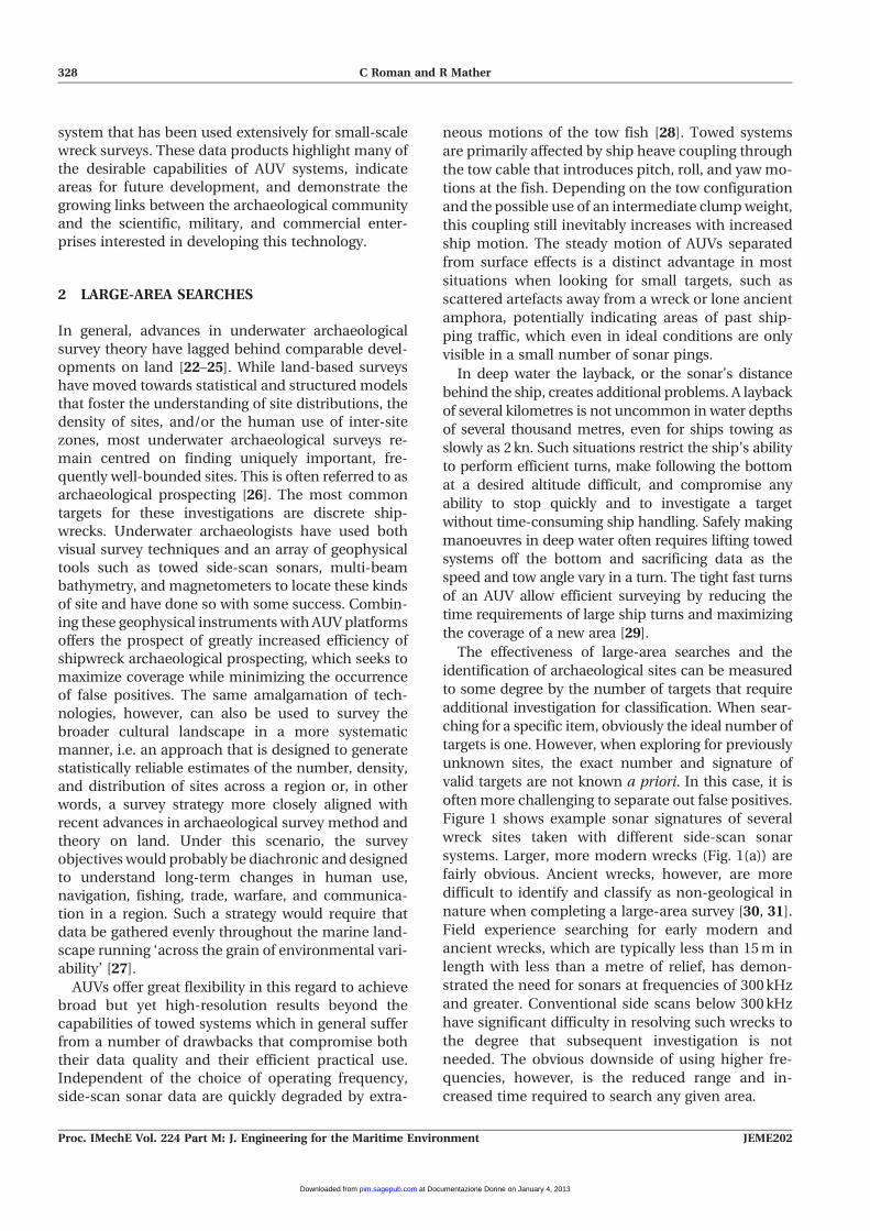
Figure 1 shows example sonar signatures of several
wreck sites taken with different side-scan sonar
systems. Larger, more modern wrecks (Fig. 1(a)) are
fairly obvious. Ancient wrecks, however, are more
difficult to identify and classify as non-geological in
nature when completing a large-area survey [30, 31].
Field experience searching for early modern and
ancient wrecks, which are typically less than 15 m in
length with less than a metre of relief, has demon-
strated the need for sonars at frequencies of 300 kHz
and greater. Conventional side scans below 300 kHz
have significant difficulty in resolving such wrecks to
the degree that subsequent investigation is not
needed. The obvious downside of using higher fre-
quencies, however, is the reduced range and in-
creased time required to search any given area.
328 C Roman and R Mather
Proc. IMechE Vol. 224 Part M: J. Engineering for the Maritime Environment JEME202
at Documentazione Donne on January 4, 2013pim.sagepub.comDownloaded from
Beyond conventional side-scan sonars, synthetic
aperture, focused, chirp and multi-ping systems
have tremendous potential for archaeological work
on AUVs. Synthetic aperture sonar (SAS) systems use
coherent signal processing to combine separate
pings to create high-resolution images which have
range-independent along-track resolution [32, 33]. To
achieve this precision, platform navigation measure-
ments are required. AUVs with inherently steady
motion and high-performance inertial navigation
sensors are ideal platforms for SAS systems and are
starting to become commercially available for survey
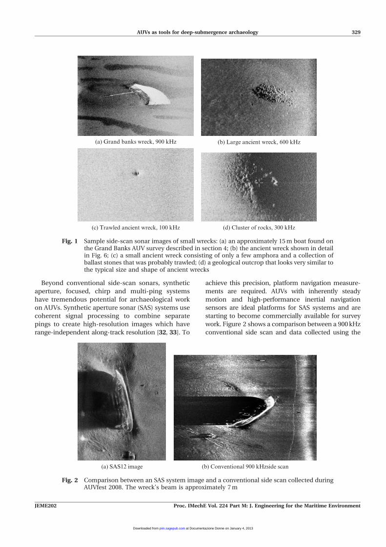
work. Figure 2 shows a comparison between a 900 kHz
conventional side scan and data collected using the
(a) Grand banks wreck, 900 kHz (b) Large ancient wreck, 600 kHz
(d) Cluster of rocks, 300 kHz(c) Trawled ancient wreck, 100 kHz
Fig. 1 Sample side-scan sonar images of small wrecks: (a) an approximately 15 m boat found onthe Grand Banks AUV survey described in section 4; (b) the ancient wreck shown in detailin Fig. 6; (c) a small ancient wreck consisting of only a few amphora and a collection ofballast stones that was probably trawled; (d) a geological outcrop that looks very similar tothe typical size and shape of ancient wrecks
(a) SAS12 image (b) Conventional 900 kHzside scan
Fig. 2 Comparison between an SAS system image and a conventional side scan collected duringAUVfest 2008. The wreck’s beam is approximately 7 m
AUVs as tools for deep-submergence archaeology 329
JEME202 Proc. IMechE Vol. 224 Part M: J. Engineering for the Maritime Environment
at Documentazione Donne on January 4, 2013pim.sagepub.comDownloaded from

180 kHz SAS12 system [34] during the AUVfest 2008
trials. The SAS12 system has a nominal resolution of
2.5 cm62.5 cm and was designed as a mine-hunting
tool for proud and partially buried objects. The obvious
advantage for marine archaeology is the ability to
identify small objects at ranges greater than would be
possible with conventional sonar systems. The current
drawbacks of SAS systems, however, are their overall
cost, the peripheral need for precise platform naviga-
tion, and the significantly increased data-processing
demands that require more power on the vehicle and
operator expertise for post-processing. As a midpoint,
many vendors now sell focused and multi-ping chirp
sonars for AUVs that are able to increase along-track
resolution. These systems enable more flexibility in
mission planning by allowing higher speeds for a given
resolution and better image fidelity at longer ranges.
3 TARGET IDENTIFICATION
The identification phase requires confirming that
targets detected in the large-area search are indeed
of archaeological interest. The difficulty in doing this
stems from the quality of the data obtained during
the large-area search and the costs associated with
additional survey efforts to obtain unambiguous
information about a site. This can, in general, be
framed as a multi-scalar problem where the larger-
area search maximizes coverage and the identifica-
tion survey maximizes fidelity. Successful strategies
in this context can exploit the dual high- and low-
frequency capabilities of side-scan sonar systems
together with visual images provided from camera
systems and magnetometers to identify ferrous
materials. Using towed sonar and optical imaging
systems the true cost of target identification can
quickly become a limiting factor. Repeated site-spe-
cific deployments with either ROV systems or by
making additional sonar passes with higher frequen-
cies at lower altitudes is time consuming and resource
intensive. In this context, AUVs have a distinct ad-
vantage to transit quickly between potential targets
and to perform small-scale detailed surveys at lower
altitudes with higher-resolution sensors. The flexibil-
ity in AUV mission planning allows these surveys to
account easily for positioning errors in the large-scale
search and efficient travel between individual sites.
3.1 Multi-scalar mapping
To attempt to merge the large-scale search and target
identification phases, joint operation of towed sys-
tems and autonomous systems offers significant
potential. In 2008, a joint survey transect stretching
from Cape Race to the edge of the Grand Banks south
of Newfoundland, Canada, a distance of approxi-
mately 240 km, was completed. This survey was
designed to experiment with new ideas about under-
water archaeological survey. The survey represented
the first phase of an anticipated multi-year investiga-
tion of the Grand Banks cultural landscape, an area
too large to hope to obtain complete coverage without
prohibitive expense. The initial survey strategy was
based on a series of radial transects, aligned with the
cardinal and intermediate points of the compass,
originating at Cape Race, Newfoundland. History
records more than 3250 known shipwrecks in New-
foundland waters, which represent multiple human
uses and impacts on one of the most historically and
archaeologically important areas in the North Atlantic.
The transect consisted of two parallel survey lines,
300 m apart (Fig. 3). Along the first line, the R/V
Endeavor towed a conventional dual-frequency side-
scan sonar (100–400 kHz) and ran its 3.5 kHz sub-
bottom profiler. Along the second line, the Atalanta
AUV (Fig. 3) collected high-frequency (300–900 kHz)
side-scan data and 675 kHz multi-beam data. The
combined suite of systems and sensors provided
high-resolution narrow coverage (120 m swaths) and
low-resolution broad coverage (300 m swaths) of the
bottom surface together with some subsurface data.
The data were used for archaeological site survey,
broad cultural landscape survey, and geological
survey.
To start the survey, the AUV was deployed and set
to loiter in an area offset from the intended ship
track. After the towed sonar was launched, the AUV
and ship started their respective parallel track lines.
This separation kept the AUV safely away from the
ship while allowing an area of overlapping data for
comparative evaluation of the two different sonar
frequencies and incidence directions. Additional
periodic loitering points were programmed into the
AUV mission to allow coordination to be main-
tained. Between these points the nominal ship speed
of 2.5 kn was adjusted slightly either to give or to take
ground from the AUV moving at a nominal 3.5 kn.
Small changes in the ship speed do not require
significant tow cable management or cause degrada-
tion of the data. At a loitering loop the ship and AUV
were able to establish acoustic modem contact and to
resynchronize their progress. In the event of a com-
munications failure, the looping behaviour main-
tained the AUV in a known area away from the ship’s
intended path. For this relatively shallow survey, less
330 C Roman and R Mather
Proc. IMechE Vol. 224 Part M: J. Engineering for the Maritime Environment JEME202
at Documentazione Donne on January 4, 2013pim.sagepub.comDownloaded from

than 200 m deep, the AUV was also commanded to
surface at a loitering point every 12 km along the line.
This helped to bound the accumulated navigation
drift by providing a Global Positioning System fix and
also provided a safety measure to establish Iridium
contact with the AUV in the event of any prolonged
acoustic communications blackout. These systematic
survey blocks are also comparable with evenly spaced
archaeological test units used in conventional archae-
ological survey.
The benefits of such a survey are increased coverage
and multiple resolutions, each obtained at their
optimal survey altitude. Further development of this
concept will entail acoustically commanding the AUV
to investigate targets quickly as they appear on the
towed side-scan system. Managing the speed of the
ship, the speed of the AUV, and the size of the
identification surveys would allow the AUV time to
make high-resolution passes over ‘interesting’ targets
and then to rejoin the ship. Such a system has several
significant benefits. The real-time human in the loop
will provide a check and initial classification of the
sonar targets before sending the AUV off for further
investigations [35]. This reduces the need for real-time
side-scan target classification algorithms looking for
wrecks which may present with various signatures. By
accomplishing the investigation at the moment of
discovery, there will be little subsequent need to
backtrack the ship and towed system for additional
looks at targets.
Significant longer-term development of this concept
could use the towed side-scan system as a dock for the
AUV. The AUV could be released from the dock when a
target is found or could periodically reconnect to the
dock for power and data transfer. AUV docking has
been accomplished for static systems [36, 37] and is
likely for moving vessels and tow bodies [38]. Access to
periodic data download, either from docking or from
compressed images telemetered via acoustic commu-
nications [35], can be used in the event of a significant
Fig. 3 Section of the joint ship-based side-scan and AUV operation. The AUV performed a high-resolution 300 kHz side scan 40 km long which was line offset from the ship towing alower-frequency swath system 100 kHz wide. Periodic holding patterns were used to keepthe ship and AUV coordinated. A 300 m lateral separation was maintained between theship and the AUV
AUVs as tools for deep-submergence archaeology 331
JEME202 Proc. IMechE Vol. 224 Part M: J. Engineering for the Maritime Environment
at Documentazione Donne on January 4, 2013pim.sagepub.comDownloaded from
discovery to stop the entire search operation without
having to wait for a complete AUV mission to finish.
3.2 Multi-sensor investigations
The archaeological community will also benefit from
the military-funded efforts related to subsurface
target classification and identification techniques.
The mine countermeasures problem has sponsored
a significant amount of research for object classifica-
tion using bottom penetration acoustics and surface
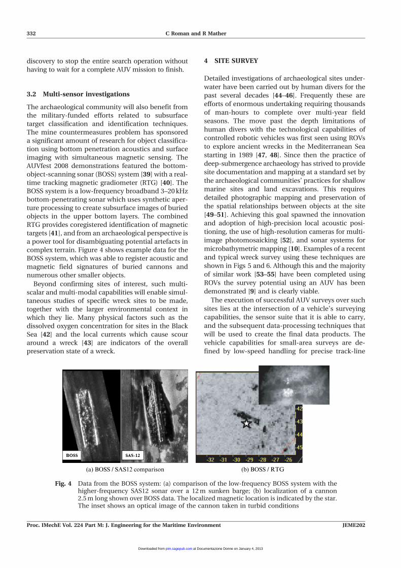
imaging with simultaneous magnetic sensing. The
AUVfest 2008 demonstrations featured the bottom-
object-scanning sonar (BOSS) system [39] with a real-
time tracking magnetic gradiometer (RTG) [40]. The
BOSS system is a low-frequency broadband 3–20 kHz
bottom-penetrating sonar which uses synthetic aper-
ture processing to create subsurface images of buried
objects in the upper bottom layers. The combined
RTG provides coregistered identification of magnetic
targets [41], and from an archaeological perspective is
a power tool for disambiguating potential artefacts in
complex terrain. Figure 4 shows example data for the
BOSS system, which was able to register acoustic and
magnetic field signatures of buried cannons and
numerous other smaller objects.
Beyond confirming sites of interest, such multi-
scalar and multi-modal capabilities will enable simul-
taneous studies of specific wreck sites to be made,
together with the larger environmental context in
which they lie. Many physical factors such as the
dissolved oxygen concentration for sites in the Black
Sea [42] and the local currents which cause scour
around a wreck [43] are indicators of the overall
preservation state of a wreck.
4 SITE SURVEY
Detailed investigations of archaeological sites under-
water have been carried out by human divers for the
past several decades [44–46]. Frequently these are
efforts of enormous undertaking requiring thousands
of man-hours to complete over multi-year field
seasons. The move past the depth limitations of
human divers with the technological capabilities of
controlled robotic vehicles was first seen using ROVs
to explore ancient wrecks in the Mediterranean Sea
starting in 1989 [47, 48]. Since then the practice of
deep-submergence archaeology has strived to provide
site documentation and mapping at a standard set by
the archaeological communities’ practices for shallow
marine sites and land excavations. This requires
detailed photographic mapping and preservation of
the spatial relationships between objects at the site
[49–51]. Achieving this goal spawned the innovation
and adoption of high-precision local acoustic posi-
tioning, the use of high-resolution cameras for multi-
image photomosaicking [52], and sonar systems for
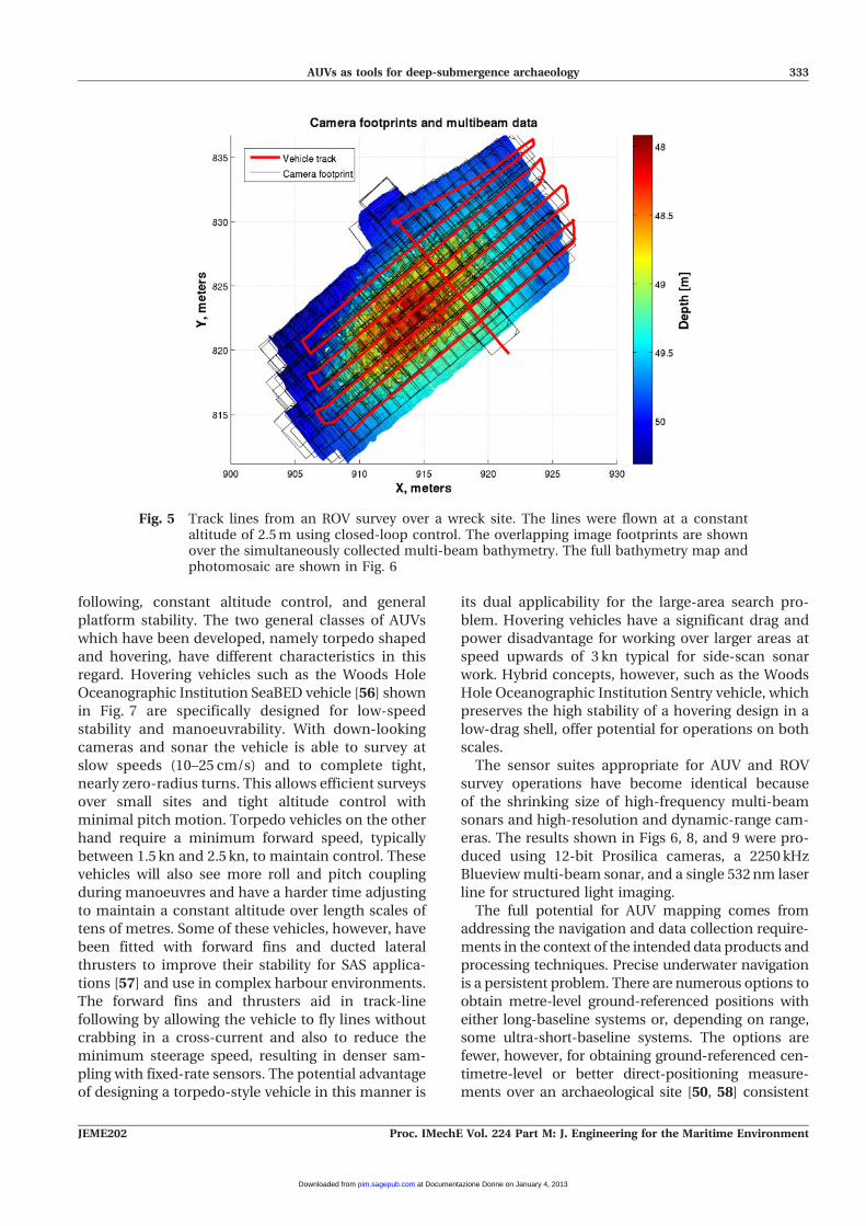
microbathymetric mapping [10]. Examples of a recent
and typical wreck survey using these techniques are
shown in Figs 5 and 6. Although this and the majority
of similar work [53–55] have been completed using
ROVs the survey potential using an AUV has been
demonstrated [9] and is clearly viable.
The execution of successful AUV surveys over such
sites lies at the intersection of a vehicle’s surveying
capabilities, the sensor suite that it is able to carry,
and the subsequent data-processing techniques that
will be used to create the final data products. The
vehicle capabilities for small-area surveys are de-
fined by low-speed handling for precise track-line
(a) BOSS / SAS12 comparison (b) BOSS / RTG
Fig. 4 Data from the BOSS system: (a) comparison of the low-frequency BOSS system with thehigher-frequency SAS12 sonar over a 12 m sunken barge; (b) localization of a cannon2.5 m long shown over BOSS data. The localized magnetic location is indicated by the star.The inset shows an optical image of the cannon taken in turbid conditions
332 C Roman and R Mather
Proc. IMechE Vol. 224 Part M: J. Engineering for the Maritime Environment JEME202
at Documentazione Donne on January 4, 2013pim.sagepub.comDownloaded from
following, constant altitude control, and general
platform stability. The two general classes of AUVs
which have been developed, namely torpedo shaped
and hovering, have different characteristics in this
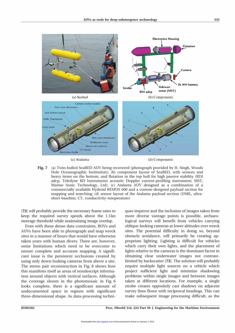
regard. Hovering vehicles such as the Woods Hole
Oceanographic Institution SeaBED vehicle [56] shown
in Fig. 7 are specifically designed for low-speed
stability and manoeuvrability. With down-looking
cameras and sonar the vehicle is able to survey at
slow speeds (10–25 cm/s) and to complete tight,
nearly zero-radius turns. This allows efficient surveys
over small sites and tight altitude control with
minimal pitch motion. Torpedo vehicles on the other
hand require a minimum forward speed, typically
between 1.5 kn and 2.5 kn, to maintain control. These
vehicles will also see more roll and pitch coupling
during manoeuvres and have a harder time adjusting
to maintain a constant altitude over length scales of
tens of metres. Some of these vehicles, however, have
been fitted with forward fins and ducted lateral
thrusters to improve their stability for SAS applica-
tions [57] and use in complex harbour environments.
The forward fins and thrusters aid in track-line
following by allowing the vehicle to fly lines without
crabbing in a cross-current and also to reduce the
minimum steerage speed, resulting in denser sam-
pling with fixed-rate sensors. The potential advantage
of designing a torpedo-style vehicle in this manner is
its dual applicability for the large-area search pro-
blem. Hovering vehicles have a significant drag and
power disadvantage for working over larger areas at
speed upwards of 3 kn typical for side-scan sonar
work. Hybrid concepts, however, such as the Woods
Hole Oceanographic Institution Sentry vehicle, which
preserves the high stability of a hovering design in a
low-drag shell, offer potential for operations on both
scales.
The sensor suites appropriate for AUV and ROV
survey operations have become identical because
of the shrinking size of high-frequency multi-beam
sonars and high-resolution and dynamic-range cam-
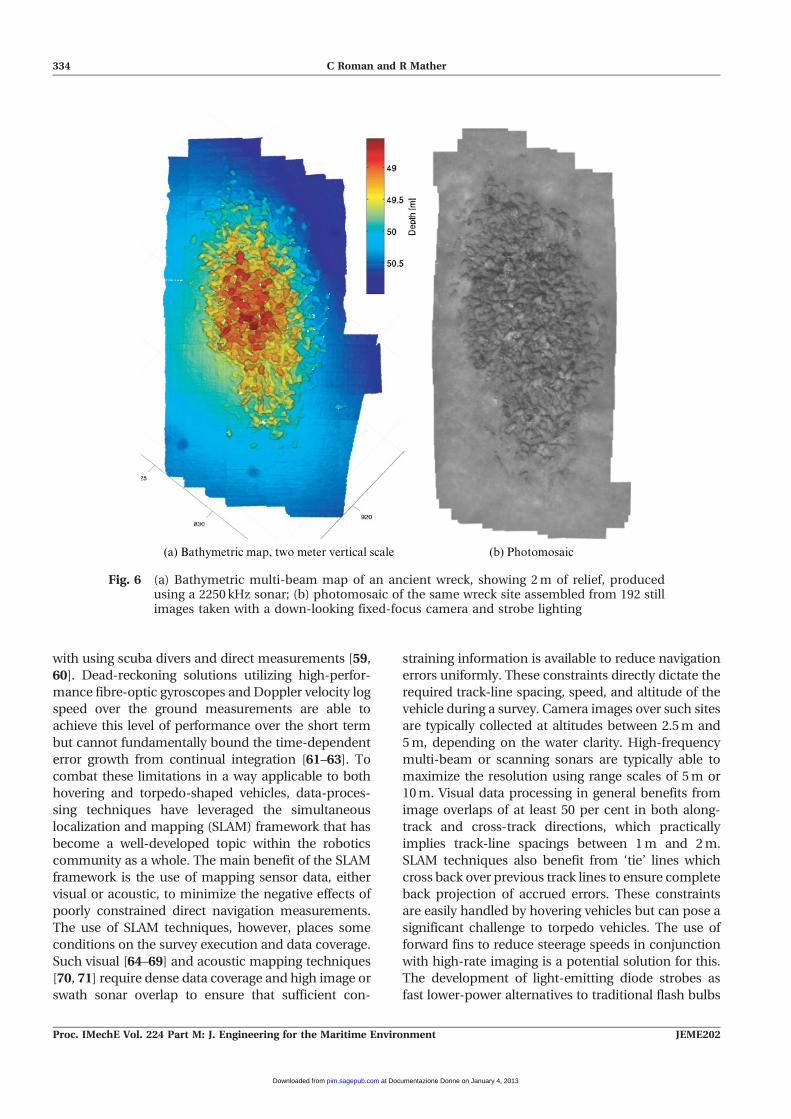
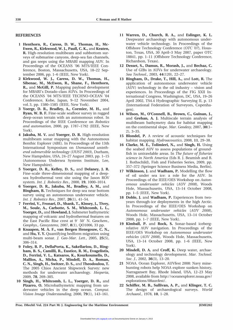
eras. The results shown in Figs 6, 8, and 9 were pro-
duced using 12-bit Prosilica cameras, a 2250 kHz
Blueview multi-beam sonar, and a single 532 nm laser
line for structured light imaging.
The full potential for AUV mapping comes from
addressing the navigation and data collection require-
ments in the context of the intended data products and
processing techniques. Precise underwater navigation
is a persistent problem. There are numerous options to
obtain metre-level ground-referenced positions with
either long-baseline systems or, depending on range,
some ultra-short-baseline systems. The options are
fewer, however, for obtaining ground-referenced cen-
timetre-level or better direct-positioning measure-
ments over an archaeological site [50, 58] consistent
Fig. 5 Track lines from an ROV survey over a wreck site. The lines were flown at a constantaltitude of 2.5 m using closed-loop control. The overlapping image footprints are shownover the simultaneously collected multi-beam bathymetry. The full bathymetry map andphotomosaic are shown in Fig. 6
AUVs as tools for deep-submergence archaeology 333
JEME202 Proc. IMechE Vol. 224 Part M: J. Engineering for the Maritime Environment
at Documentazione Donne on January 4, 2013pim.sagepub.comDownloaded from
with using scuba divers and direct measurements [59,
60]. Dead-reckoning solutions utilizing high-perfor-
mance fibre-optic gyroscopes and Doppler velocity log
speed over the ground measurements are able to
achieve this level of performance over the short term
but cannot fundamentally bound the time-dependent
error growth from continual integration [61–63]. To
combat these limitations in a way applicable to both
hovering and torpedo-shaped vehicles, data-proces-
sing techniques have leveraged the simultaneous
localization and mapping (SLAM) framework that has
become a well-developed topic within the robotics
community as a whole. The main benefit of the SLAM
framework is the use of mapping sensor data, either
visual or acoustic, to minimize the negative effects of
poorly constrained direct navigation measurements.
The use of SLAM techniques, however, places some
conditions on the survey execution and data coverage.
Such visual [64–69] and acoustic mapping techniques
[70, 71] require dense data coverage and high image or
swath sonar overlap to ensure that sufficient con-
straining information is available to reduce navigation
errors uniformly. These constraints directly dictate the
required track-line spacing, speed, and altitude of the
vehicle during a survey. Camera images over such sites
are typically collected at altitudes between 2.5 m and
5 m, depending on the water clarity. High-frequency
multi-beam or scanning sonars are typically able to
maximize the resolution using range scales of 5 m or
10 m. Visual data processing in general benefits from
image overlaps of at least 50 per cent in both along-
track and cross-track directions, which practically
implies track-line spacings between 1 m and 2 m.
SLAM techniques also benefit from ‘tie’ lines which
cross back over previous track lines to ensure complete
back projection of accrued errors. These constraints
are easily handled by hovering vehicles but can pose a
significant challenge to torpedo vehicles. The use of
forward fins to reduce steerage speeds in conjunction
with high-rate imaging is a potential solution for this.
The development of light-emitting diode strobes as
fast lower-power alternatives to traditional flash bulbs
(a) Bathymetric map, two meter vertical scale (b) Photomosaic
Fig. 6 (a) Bathymetric multi-beam map of an ancient wreck, showing 2 m of relief, producedusing a 2250 kHz sonar; (b) photomosaic of the same wreck site assembled from 192 stillimages taken with a down-looking fixed-focus camera and strobe lighting
334 C Roman and R Mather
Proc. IMechE Vol. 224 Part M: J. Engineering for the Maritime Environment JEME202
at Documentazione Donne on January 4, 2013pim.sagepub.comDownloaded from
[72] will probably provide the necessary frame rates to
keep the required survey speeds above the 1.5 kn
steerage threshold while maintaining image overlap.
Even with these dense data constraints, ROVs and
AUVs have been able to photograph and map wreck
sites in a manner of hours that would have otherwise
taken years with human divers. There are, however,
some limitations which need to be overcome to
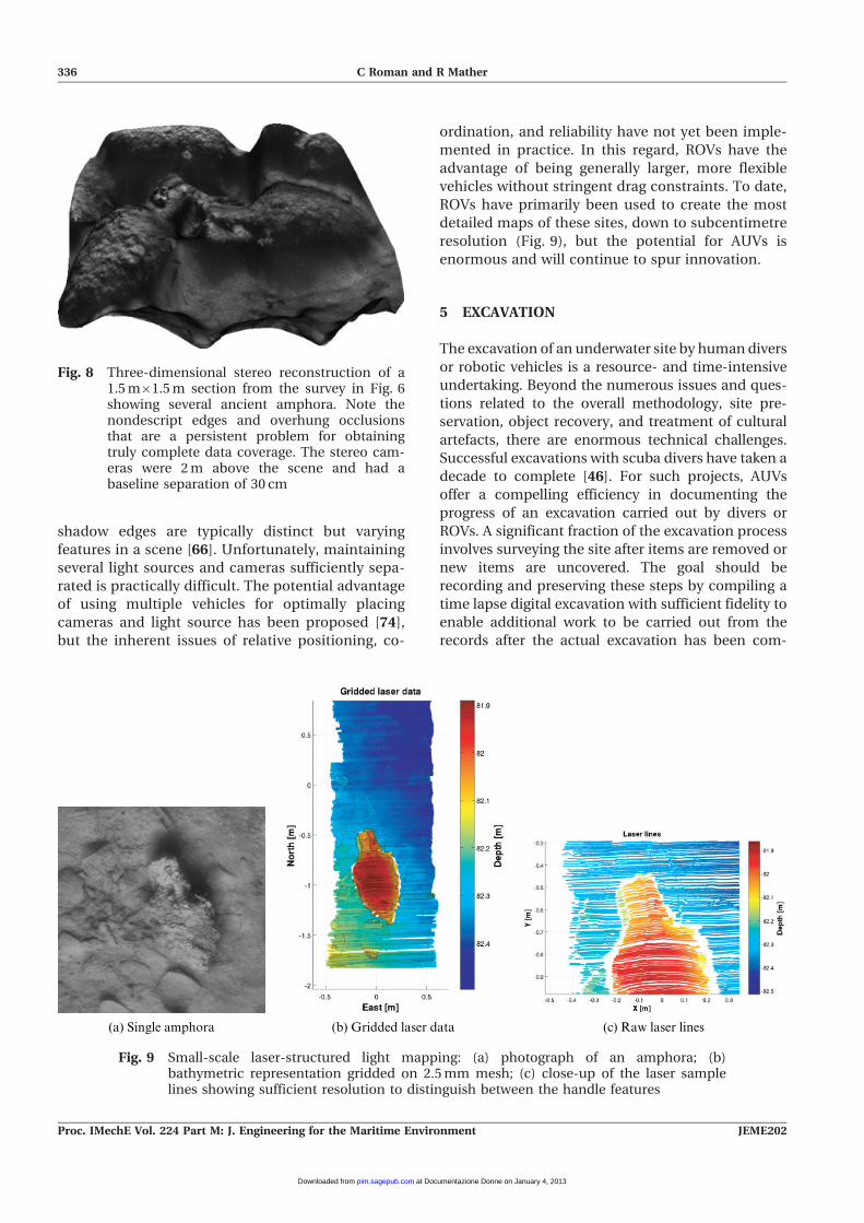
ensure complete and accurate mapping. A signifi-
cant issue is the persistent occlusions created by
using only down-looking cameras from above a site.
The stereo pair reconstruction in Fig. 8 shows how
this manifests itself as areas of nondescript informa-
tion around objects with vertical surfaces. Although
the coverage shown in the photomosaic in Fig. 6
looks complete, there is a significant amount of
undocumented space in regions with significant
three-dimensional shape. As data-processing techni-
ques improve and the inclusion of images taken from
more diverse vantage points is possible, archaeo-
logical surveys will benefit from vehicles carrying
oblique-looking cameras at lower altitudes over wreck
sites. The potential difficulty in doing so, beyond
obstacle avoidance, will primarily be creating ap-
propriate lighting. Lighting is difficult for vehicles
which carry their own lights, and the placement of
lights relative to the cameras is the dominant factor in
obtaining clear underwater images not contrast-
limited by backscatter [73]. The solution will probably
require multiple light sources on a vehicle which
project sufficient light and minimize shadowing
problems within single images and between images
taken at different locations. For example, a single
strobe creates oppositely cast shadows on adjacent
survey lines flown with reciprocal headings. This can
make subsequent image processing difficult, as the
(a) Seabed (b) Components
(d) Components(c) Atalanta
Fig. 7 (a) Twin-hulled SeaBED AUV being recovered (photograph provided by H. Singh, WoodsHole Oceanographic Institution); (b) component layout of SeaBED, with sensors andheavy items on the bottom, and flotation in the top hull for high passive stability (RDIadcp, Teledyne RD Instruments acoustic Doppler current-profiling instrument; MST,Marine Sonic Technology, Ltd); (c) Atalanta AUV designed as a combination of acommercially available Hydroid REMUS 600 and a custom-designed payload section formapping and searching; (d) sensor layout of the Atalanta payload section (USBL, ultra-short-baseline; CT, conductivity–temperature)
AUVs as tools for deep-submergence archaeology 335
JEME202 Proc. IMechE Vol. 224 Part M: J. Engineering for the Maritime Environment
at Documentazione Donne on January 4, 2013pim.sagepub.comDownloaded from
shadow edges are typically distinct but varying
features in a scene [66]. Unfortunately, maintaining
several light sources and cameras sufficiently sepa-
rated is practically difficult. The potential advantage
of using multiple vehicles for optimally placing
cameras and light source has been proposed [74],
but the inherent issues of relative positioning, co-
ordination, and reliability have not yet been imple-
mented in practice. In this regard, ROVs have the
advantage of being generally larger, more flexible
vehicles without stringent drag constraints. To date,
ROVs have primarily been used to create the most
detailed maps of these sites, down to subcentimetre
resolution (Fig. 9), but the potential for AUVs is
enormous and will continue to spur innovation.
5 EXCAVATION
The excavation of an underwater site by human divers
or robotic vehicles is a resource- and time-intensive
undertaking. Beyond the numerous issues and ques-
tions related to the overall methodology, site pre-
servation, object recovery, and treatment of cultural
artefacts, there are enormous technical challenges.
Successful excavations with scuba divers have taken a
decade to complete [46]. For such projects, AUVs
offer a compelling efficiency in documenting the
progress of an excavation carried out by divers or
ROVs. A significant fraction of the excavation process
involves surveying the site after items are removed or
new items are uncovered. The goal should be
recording and preserving these steps by compiling a
time lapse digital excavation with sufficient fidelity to
enable additional work to be carried out from the
records after the actual excavation has been com-
(a) Single amphora (b) Gridded laser data (c) Raw laser lines
Fig. 9 Small-scale laser-structured light mapping: (a) photograph of an amphora; (b)bathymetric representation gridded on 2.5 mm mesh; (c) close-up of the laser samplelines showing sufficient resolution to distinguish between the handle features
Fig. 8 Three-dimensional stereo reconstruction of a1.5 m61.5 m section from the survey in Fig. 6showing several ancient amphora. Note thenondescript edges and overhung occlusionsthat are a persistent problem for obtainingtruly complete data coverage. The stereo cam-eras were 2 m above the scene and had abaseline separation of 30 cm
336 C Roman and R Mather
Proc. IMechE Vol. 224 Part M: J. Engineering for the Maritime Environment JEME202
at Documentazione Donne on January 4, 2013pim.sagepub.comDownloaded from

pleted. The repeatable survey capabilities of AUVs
could be used to make periodic photographic and
topographic maps of wreck sites in far less time than
would be possible with human divers and even pilot-
intensive ROV surveys. This would significantly
reduce many of the true costs for such excavations
by shortening the total time requirements and
enabling appropriate resources and man-power to
be better allocated. The efficiency of collecting data
and processing it for mapping and change detection
will also result in feedback to create better real-time
planning of on-site operations. Subbottom profilers
and sonars such as the BOSS system will also be
extremely valuable when attempting excavations with
purely robotic tools.
6 SUMMARY
Looking forwards, there are many specific aspects of
marine archaeology that will substantially benefit
from the use of AUV systems. Their large-scale
search capabilities provide efficient coverage and
operation beyond what is currently possible with
towed systems alone. Additionally, the coordinated
use of AUVs and towed systems is a promising future
direction which offers multi-scalar mapping and
mission adaptation to increase overall productivity
and target investigations. For site mapping and
recording, AUVs are able to perform detailed surveys
and to obtain coregistered multi-sensor data. In
shallow water they can provide high-fidelity data
and complement efforts of human divers to produce
significant time savings. The specific requirements
for this work translate to several design aspects for
hovering and torpedo-style vehicles. The ability to fly
dense survey patterns and to achieve high along-
track and cross-track sensor overlap is essential to
make full use of the many subsequent data-proces-
sing techniques able to handle navigation uncer-
tainty robustly. Future developments in these areas
for the broader set of AUV applications will also
ensure that AUVs play an increasingly beneficial role
in marine archaeological work. Directly connecting
these technologies, however, with the needs and
demands of the archaeology community remains an
open question in many aspects. For large-scale
searches and target identification, AUVs are unques-
tionably the most powerful tools available, but a
complete cost–benefit analysis including the ex-
penses for ship time, the assets themselves, and
the personnel to run them is difficult to generalize
and is project specific. Access by the archaeological
community to these systems is, however, increasing
through collaborations such as AUVfest 2008. Part-
nerships developed during AUVfest will make AUVs
available to the archaeological community for an
upcoming project at the Thunder Bay National
Marine Sanctuary and Underwater Preserve in Lake
Huron sponsored in part by the NOAA Office of
Ocean Exploration and Research (OER). The inclu-
sion of submerged cultural resource surveys into the
planning processes of agencies such as the US
Minerals Management Service, which is responsible
for permitting offshore energy projects, will also
provide multi-use archaeological and geological
data. Projects by companies such as C & C
Technologies in the Gulf of Mexico [11] and partner-
ships on Noways’s Ormen Lange gas field [75]
demonstrate the use of these assets for cultural
assessment when prospecting in economically im-
portant areas. For detailed site surveys there are still
numerous questions pertaining to the achievable
mapping accuracies that ROV and AUV systems can
actually provide. In general, it is difficult to predict
and convey many of the errors that are specific to
each sensor type and generally vary spatially over a
site. The millimetre-level accuracy now afforded to
the land archaeology community by common
commercial laser scanning systems is becoming
more achievable for deep-submergence archaeology.
A best practice, however, for translating these
vehicle-based optical and acoustic mapping surveys
into useful archaeological data and site maps is still
being developed [60].
ACKNOWLEDGEMENTS
The authors would like to thank Dr R. Ballard andthe Institute for Exploration based at Mystic Aqua-rium for leading several of the cited projects withfunding from the NOAA OER, ONR, and NationalGeographic. The authors would also like to thank DrH. Singh at Woods Hole Oceanographic Institution,whose photomosaicking software was used to pro-duce the photomosaic shown in Fig. 6. The ONR andNOAA AUVfest 2008 was organized by F. Cantelas(NOAA OER), D. Crimmins (Naval Undersea WarfareCenter), W. Schopfel (ONR), and many others whomade it a very successful demonstration of Navycapabilities for the archaeological community. Thesonar system teams mentioned here were led by T.Clem (BOSS), R. Holtzapple (BOSS), and T. Matthews(SAS12), all from the Naval Surface Warfare Center,Panama City.
F Authors 2010
AUVs as tools for deep-submergence archaeology 337
JEME202 Proc. IMechE Vol. 224 Part M: J. Engineering for the Maritime Environment
at Documentazione Donne on January 4, 2013pim.sagepub.comDownloaded from
REFERENCES
1 Henthorn, R., Caress, D. W., Thomas, H., Mc-Ewen, R., Kirkwood, W. J., Paull, C. K., and Keaten,R. High-resolution multibeam and subbottom sur-veys of submarine canyons, deep-sea fan channels,and gas seeps using the MBARI mapping AUV. InProceedings of the OCEANS ’06 MTS/IEEE Con-ference, Boston, Massachusetts, USA, 18–22 Sep-tember 2006, pp. 1–6 (IEEE, New York).
2 Kirkwood, W. J., Caress, D. W., Thomas, H.,Sibenac, M., McEwen, R., Shane, F., Henthorn,R., and McGill, P. Mapping payload developmentfor MBARI’s Dorado-class AUVs. In Proceedings ofthe OCEANS ’04 MTS/IEEE TECHNO-OCEAN ’04Conference, Kobe, Japan, 9–12 November 2004,vol. 3, pp. 1580–1585 (IEEE, New York).
3 Yoergr, D. R., Bradley, A., Cormier, M. H., andRyan, W. B. F. Fine-scale seafloor survey in ruggeddeep-ocean terrain with an autonomous robot. InProceedings of the IEEE Conference on Roboticsand automation, 2000, pp. 1787–1792 (IEEE, NewYork).
4 Jakuba, M. V. and Yoerger, D. R. High-resolutionmultibeam sonar mapping with the AutonomousBenthic Explorer (ABE). In Proceedings of the 13thInternational Symposium on Unmanned unteth-ered submersible technology (UUST 2003), Durham,New Hampshire, USA, 24–27 August 2003, pp. 1–15(Autonomous Undersea Systems Institute, Lee,New Hampshire).
5 Yoerger, D. R., Kelley, D. S., and Delaney, J. R.Fine-scale three-dimensional mapping of a deep-sea hydrothermal vent site using the Jason ROVsystem. Int. J. Robotics Res., 2000, 19, 1000–1014.
6 Yoerger, D. R., Jakuba, M., Bradley, A. M., andBingham, B. Techniques for deep sea near bottomsurvey using an autonomous underwater vehicle.Int. J. Robotics Res., 2007, 26(1), 41–54.
7 Ferrini, V., Fronari, D., Shank, T., Kinsey, J., Tivey,M., Soule, A., Carbotte, S. M., Whitcomb, L. L.,Yoerger, D., and Howland, J. Submeter bathymetricmapping of volcanic and hydrothermal features onthe East Pacific Rise crest at 9u 509 N. Geochem.,Geophys., Geosystems, 2007, 8(1), QO1006, 33 pp.
8 Knaapen, M. A. F., van Bergen Henegouw, C. N.,and Hu, Y. Y. Quantifying bedform migration usingmulti-beam sonar. J. Geo-Mar. Lett., 2005, 25(5),306–314.
9 Foley, B. P., DellaPorta, K., Sakellariou, D., Bing-ham, B. S., Camilli, R., Eustice, R. M., Evagelistis,D., Ferrini, V. L., Katsaros, K., Kourkoumelis, D.,Mallios, A., Micha, P., Mindell, D. A., Roman,C. N., Singh, H., Switzer, D. S., and Theodoulou, T.The 2005 Chios Ancient Shipwreck Survey: newmethods for underwater archaeology. Hesperia,2009, 78, 269–305.
10 Singh, H., Whitcomb, L. L., Yoerger, D. R., andPizarro, O. Microbathymetric mapping from un-derwater vehicles in the deep ocean. Comput.Vision Image Understanding, 2000, 79(1), 143–161.
11 Warren, D., Church, R. A., and Eslinger, K. L.Deepwater archaeology with autonomous under-water vehicle technology. In Proceedings of theOffshore Technology Conference (OTC ’07), Hous-ton, Texas, USA, 30 April–3 May 2007, paper OTC18841, pp. 1–11 (Offshore Technology Conference,Richardson, Texas).
12 Desset, S., Damus, R., Morash, J., and Bechaz, C.Use of GIBs in AUVs for underwater archaeology.Sea Technol., 2003, 44(120), 22–27.
13 Bingham, D., Drake, T., Hill, A., and Lott, R. Theapplication of autonomous underwater vehicle(AUV) technology in the oil industry – vision andexperiences. In Proceedings of the FIG XXII In-ternational Congress, Washington, DC, USA, 19–26April 2002, TS4.4 Hydrographic Surveying II, p. 13(International Federation of Surveyors, Copenha-gen).
14 Wilson, M., O’Connell, B., Brown, C., Guinan, J.,and Grehan, A. J. Multiscale terrain analysis ofmultibeam bathymetry data for habitat mappingon the continental slope. Mar. Geodesy, 2007, 30(1–2), 3–35.
15 Blondel, P. A review of acoustic techniques forhabitat mapping. Hydroacoustics, 2008, 11, 29–38.
16 Clarke, M. E., Tolimieri, N., and Singh, H. Usingthe seabed AUV to assess populations of ground-fish in untrawlable areas. In The future of fisheriesscience in North America (Eds R. J. Beamish and B.J. Rothschild), Fish and Fisheries Series, 2009, pp.357–372 (Springer Science Business Media, Berlin).
17 Wilkinson, J. and Wadham, P. Modelling the flowof oil under sea ice: a role for the AUV. InProceedings of the IEEE/OES Workshop on Auton-omous underwater vehicles (AUV 2008), WoodsHole, Massachusetts, USA, 13–14 October 2008,pp. 1–5 (IEEE, New York).
18 Doble, J. and Wadham, P. Experiences from two-years through-ice deployments in the high Arctic.In Proceedings of the IEEE/OES Workshop onAutonomous underwater vehicles (AUV 2008),Woods Hole, Massachusetts, USA, 13–14 October2008, pp. 1–7 (IEEE, New York).
19 Kimball, P. and Rock, S. Sonar-based iceberg-relative AUV navigation. In Proceedings of theIEEE/OES Workshop on Autonomous underwatervehicles (AUV 2008), Woods Hole, Massachusetts,USA, 13–14 October 2008, pp. 1–6 (IEEE, NewYork).
20 Mindell, D. A. and Croff, K. Deep water, archae-ology and technology development. Mar. Technol.Soc. J., 2002, 36(3), 13–20.
21 NOAA. Ocean Explorer, AUVfest 2008: Navy mine-hunting robots help NOAA explore sunken history,Narragansett Bay, Rhode Island, USA, 12–23 May2008, available from http://oceanexplorer.noaa.gov/explorations/08auvfest/.
22 Schiffer, M. B., Sullivan, A. P., and Klinger, T. C.The design of archaeological surveys. WorldArchaeol., 1978, 10, 1–28.
338 C Roman and R Mather
Proc. IMechE Vol. 224 Part M: J. Engineering for the Maritime Environment JEME202
at Documentazione Donne on January 4, 2013pim.sagepub.comDownloaded from
23 Ammerman, A. J. Surveys and archaeologicalresearch. A. Rev. Anthropol., 1981, 10, 63–68.
24 Alcock, S. E. and Cherry, J. F. (Eds) Side-by-sidesurvey: comparative regional studies in the Medi-terranean world, 2004 (Oxbow Books, Oxford).
25 Keller, D. R. and Rupp, D. W. (Eds) Archaeologicalsurvey in the Mediterranean area, BAR InternationalSeries 155, 1983 (British Archaeological Reports,Oxford).
26 Banning, E. B. Archaeological survey, 2002 (Kluwer–Plenum, New York).
27 Cherry, J. F. Frogs round the pond: perspectives oncurrent archaeological survey projects in theMediterranean region. In Archaeological survey inthe Mediterranean area (Eds D. R. Keller and D. W.Rupp, BAR International Series 155, 1983, pp. 375–416 (British Archaeological Reports, Oxford).
28 Cobra, D. T., Oppenheim, A. V., and Jaffe, J. S.Geometric distortions in side-scan sonar images: aprocedure for their estimation and correction. IEEEJ. Oceanic Engng, 1992, 17(3), 252–268.
29 Chance, T. S., Kleiner, A. A., and Northcutt, J. G.The autonomous underwater vehicle (AUV): a costeffective alternative. In Integrated coastal zonemanagement: strategies and tools (Ed. A. Pink),2000, pp. 65–69 (ICG Publishing, London).
30 Sakellariou, D., Georgiou, P., Mallios, A., Kapsi-malis, V., Kourkoumelis, D., Micha, P., Theodou-lou, T., and Dellaporta, K. Searching for ancientshipwrecks in the Aegean Sea: the discovery ofChios and Kythnos Hellenistic wrecks with the useof marine geological–geophysical methods. Int. J.Naut. Archaeol., 2007, 36(2), 365–381.
31 Church, R. A. and Warren, D. Sound methods: thenecessity of high-resolution geophysical data forplanning deepwater archaeological projects. Int. J.Hist. Archaeol., 2008, 12(2), 103–119.
32 Hansen, R. E., Hagen, P. E., and Telle, H. S.Synthetic aperture sonar: a tool in underwaterarchaeology. In Proceedings of the Third Conferenceand Exhibition on Underwater acoustic measure-ments: technologies and results, Nafplion, Greece,21–26 June 2009, pp. 1–6 (FORTH/IACM, Heraklion).
33 Hagen, P. E., Hansen, R. E., and Midtgaard, Ø. SASand side scan sonar systems compared: experi-mental results from HUGIN AUVs. In Proceedingsof the Second Conference and Exhibition onUnderwater acoustic measurements: technologiesand results, Crete, Greece, 25–29 June 2007, pp.1–8 (FORTH/IACM, Heraklion).
34 Matthews, A. D., Montgomery, T. C., Cook, D. A.,Oeschger, J. W., and Stroud, J. S. 12.759 syntheticaperture sonar (SAS), high resolution and automatictarget recognition. In Proceedings of the OCEANS ’06MTS/IEEE Conference, Boston, Massachusetts, USA,18–22 September 2006, pp. 1–7 (IEEE, New York).
35 Stokey, R. P., Freitag, L. E., and Grund, M. D. Acompact control language for AUV acoustic com-munication. In Proceedings of the OCEANS ’05MTS/IEEE Conference, Washington, DC, USA, 19–
23 September 2005, Vol. 2, pp. 1133–1137 (IEEE,New York).
36 Allen, B., Austin, T., Forrester, N., Goldsborough,R., Kukulya, A., Packard, G., Purcell, M., andStokey, R. Autonomous docking demonstrationswith enhanced REMUS technology. In Proceedingsof the OCEANS ’06 MTS/IEEE Conference, Boston,Massachusetts, USA, 18–22 September 2006, pp.1–6 (IEEE, New York).
37 McEwen, R. S., Hobson, B. W., McBride, L., andBellingham, J. G. Docking control system for a 54-cm diameter (21-in) AUV. IEEE J. Oceanic Engng,2008, 33(4), 550–562.
38 Bingham, B., Prechtl, E., and Wilson, R. Designrequirements for autonomous multivehicle surfaceunderwater operations. Mar. Technol. Soc. J., 2009,43(2), 61–72.
39 Schock, S. G., Wulf, J., Quentin, G., and Sara, J.Synthetic aperture processing of buried objectscanning sonar data. In Proceedings of theOCEANS ’05 MTS/IEEE Conference, Washington,DC, USA, 19–23 September 2005, pp. 2236–2241(IEEE, New York).
40 Clem, T. R. Superconducting magnetic gradi-ometers for underwater target detection. Nav.Engrs J., 2009, 110(1), 139–149.
41 Vaizer, L., Lathrop, J. D., and Bono, J. Localizationof magnetic dipole targets. In Proceedings of theOCEANS ’04 MTS/IEEE TECHNO-OCEAN ’04 Con-ference, Kobe, Japan, 9–12 November 2004, pp.869–873 (IEEE, New York).
42 Ballard, R. (Ed.) Archaeological oceanography, 2008(Princeton University Press, Princeton, New Jersey).
43 Quinn, R. The role of scour in shipwreck siteformation processes and the preservation of wreckassociated scour signatures in the sedimentaryrecord – evidence from seabed and sub-surfacedata. J. Archaeol. Sci., 2006, 33(10), 1419–1432.
44 Bass, G. F. New techniques of archaeology andGreek shipwrecks of the sixth and fifth centuriesBC. Proc. Am. Phil. Soc., 2006, 150(1), 1–14.
45 Green, J., Matthews, S., and Turanli, T. Under-water archaeological surveying using PhotoMode-ler, VirtualMapper: different applications for dif-ferent problems. Int. J. Naut. Archaeol., 2002, 31(2),283–292.
46 Pulak, J. The Uluburun shipwreck: an overview.Int. J. Naut. Archaeol., 1998, 27(3), 188–224.
47 Ballard, R. D., McCann, A. M., Yoerger, D., Whit-comb, L., Mindell, D., Oleson, J., Singh, H., Foley,B., Adams, J., and Picheota, D. The discovery ofancient history in the deep sea using advanceddeep submergence technology. Deep Sea Res., 2000,1(47), 1591–1620.
48 Ballard, R., Stager, L., Master, D., Yoerger, D.,Mindell, D., Whitcomb, L., Singh, H., and Piechota,D. Iron age shipwrecks in deep water off Ashkelon,Israel. Am. J. Archeol., 2002, 106(2), 151–168.
49 Foley, B. P. and Mindell, D. A. Precision surveyand archaeological methodology in deep water.J. Hellenic Inst. Mar. Archaeol., 2002, 6, 49–56.
AUVs as tools for deep-submergence archaeology 339
JEME202 Proc. IMechE Vol. 224 Part M: J. Engineering for the Maritime Environment
at Documentazione Donne on January 4, 2013pim.sagepub.comDownloaded from
50 Mindell, D. Precision navigation and remotesensing for underwater archaeology. In Remotesensing in archaeology (Eds J. R. Wiseman and F. El-Baz), 2007, pp. 499–511 (Springer, New York).
51 Conte, G., Zanoli, S. M., Scaradozzi, D., Gambella,L., and Calabro, V. Underwater archeology mis-sions design for data gathering automation. InProceedings of the 16th Mediterranean Conferenceon Control and automation, Ajaccio, Corsica,France, 25–27 June 2008, pp. 1083–1088 (IEEE,New York).
52 Singh, H., Adams, J., Foley, B., and Mindell, D. A.Imaging underwater for archeology. J. Field Arch-aeol., 2000, 27(3), 319–328.
53 Ludvigsen, M., Sortland, B., Johnsen, G., andSingh, H. Applications of geo-referenced under-water photo mosaics in marine biology andarchaeology. Oceanography, 2007, 20(4), 74–83.
54 Drap, P., Seinturier, J., Scaradozzi, D., Gambogi,P., Longd, L., and Gauche, F. Photogrammetry forvirtual exploration of underwater archeologicalsites. In Proceedings of the XXI CIPA Symposium,Athens, Greece, 1–6 October 2007, pp. 1–6 (Inter-national Scientific Committee for Documentationof Cultural Heritage).
55 Eustice, R. M., Singh, H., Leonard, J. J., andWalter, M. R. Visually mapping the RMS Titanic:conservative covariance estimates for SLAM infor-mation filters. Int. J. Robotics Res., 2006, 25(12),1223–1242.
56 Singh, H., Can, A., Eustice, R., Lerner, S., McPhee,N., Pizarro, O., and Roman, C. SeaBED AUV offersnew platform for high-resolution imaging. EOS,Trans. Am. Geophys. Un., 2004, 85(31), 289, 294–295.
57 Stokey, R. P., Roup, A., von Alt, C., Allen, B.,Forrester, N., Austin, T., Goldsborough, R., Pur-cell, M., Jaffre, F., Packard, G., and Kukulya, A.Development of the REMUS 600 autonomousunderwater vehicle. In Proceedings of the OCEANS’05 MTS/IEEE Conference, Washington, DC, USA,19–23 September 2005, vol. 2, pp. 1301–1304 (IEEE,New York).
58 Kinsey, J. C., Eustice, R. M., and Whitcomb, L. L. Asurvey of underwater vehicle navigation: recentadvances and new challenges. In Proceedings ofthe Seventh IFAC Conference on Manoeuvring andcontrol of marine craft (MCMC ’06), Lisbon,Portugal, 20–22 September 2006, pp. 1–12 (IFAC,New York).
59 Holt, P. An assessment of quality in underwaterarchaeological surveys using tape measures. Int. J.Naut. Archaeol., 2003, 32(2), 246–251.
60 Adams, J. Alchemy or science? Compromisingarchaeology in the deep sea. J. Maritime Archaeol.,2007, 2(1), 48–56.
61 Whitcomb, L. L., Yoerger, D. R., and Singh, H.Advances in Doppler-based navigation of under-
water robotic vehicles. In Proceedings of the IEEEConference on Robotics and automation, Detroit,Michigan, 1999, vol. 1, pp. 399–406 (IEEE, New York).
62 Gaiffe, T. Ixsea’s AUV navigation system. Under-water Mag., 2002 January–February.
63 Kinsey, J. C. and Whitcomb, L. L. In-situ calibra-tion of attitude and Doppler sensors for precisionunderwater vehicle navigation: theory and experi-ment. IEEE J. Oceanic Engng, 2007, 32(2), 286–299.
64 Mahon, I. J., Williams, S. B., Johnson-Roberson,M., and Pizarro, O. Efficient view-based SLAMusing visual loop closures. IEEE Trans. Robotics,2008, 24(5), 1002–1014.
65 Eustice, R. M., Pizarro, O., and Singh, H. Visuallyaugmented navigation for autonomous underwatervehicles. IEEE J. Oceanic Engng, 2007, 33, 103–122.
66 Pizarro, O. and Singh, H. Toward large-areamosaicing for underwater scientific applications.IEEE J. Oceanic Engng, 2003, 28(4), 651–672.
67 Gu, F. and Rzhanov, Y. Optimal image blendingfor underwater mosaics. In Proceedings of theOCEANS ’06 MTS/IEEE Conference, Boston, Mas-sachusetts, USA, 18–22 September 2006, pp. 1–5(IEEE, New York).
68 Gracias, N. and Santos-Victor, J. Underwater videomosaics as visual navigation maps. Comput. VisionImage Understanding, 2000, 79, 66–91.
69 Gracias, N., van der Zwaan, S., Bernardino, A.,and Santos-Victor, J. Mosaic based navigation forautonomous underwater vehicles. IEEE J. OceanicEngng, 2003, 28(4), 609–624.
70 Roman, C. and Singh, H. A self-consistent bathy-metric mapping algorithm. J. Field Robotics, 2007,24(1–2), 23–50.
71 Barkby, S., Williams, S. B., Pizarro, O., andJakuba, M. V. An efficient approach to bathymetricSLAM. In Proceedings of the 2009 IEEE/RSJ Inter-national Conference on Intelligent robots andsystems, St Louis, Missouri, USA, 11–15 October2009, pp. 219–224 (IEEE, New York).
72 Howland, J., Farr, N., and Singh, H. Field test of anew camera/LED strobe system. In Proceedings ofthe OCEANS ’06 MTS/IEEE Conference, Boston,Massachusetts, USA, 18–22 September 2006, pp.1–4 (IEEE, New York).
73 Jaffe, J. S. Computer modeling and the design ofoptimal underwater imaging systems. IEEE J.Oceanic Engng, 1990, 15(2), 101–111.
74 Jaffe, J. S. Multi-autonomous underwater vehicleoptical imaging for extended performance. InProceedings of the OCEANS 2007 – Europe MTS/IEEE Conference and Exhibition, Aberdeen, UK,18–21 June 2007, pp. 1–4 (IEEE, New York).
75 Soreide, F. and Jasinski, M. E. Ormen Lange,Norway – the deepest dig. Int. J. Naut. Archaeol.,2008, 37(2), 380–384.
340 C Roman and R Mather
Proc. IMechE Vol. 224 Part M: J. Engineering for the Maritime Environment JEME202
at Documentazione Donne on January 4, 2013pim.sagepub.comDownloaded from