control architectures for autonomous underwater vehicles ... · control architectures for...
TRANSCRIPT
Control Architectures for Autonomous Underwater Vehicles
Kimon P. Valavanis, Denis Gracanin, Maja Matijasevic, Ramesh Kolluru, and Georgios A. Demetriou
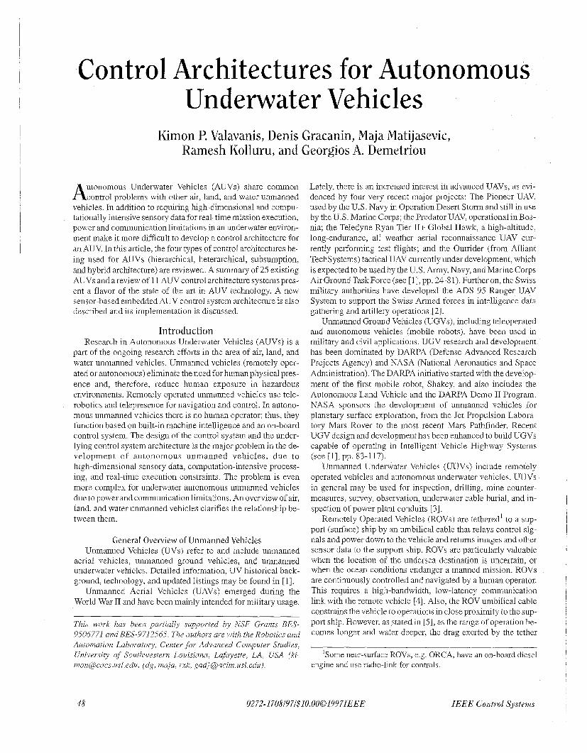
utonomous Underwater Vehicles (AUVs) share common A control problems with other air, land, and water unmanned vehicles. In addition to requiring high-dimensional and compu- tationally intensive sensory data for real-time mission execution, power and communication limitations in an underwater environ- ment make it more difficult to develop a control architecture for an AUV. In this article, the four types of control architectures be- ing used for AUVs (hierarchical, heterarchical, subsumption, and hybrid architecture) are reviewed. A summary of 25 existing AUVs and a review of 11 AUV control architecture systems pres- ent a flavor of the state of the art in AUV technology. A new sensor-based embedded AUV control system architecture is also described and its implementation is discussed.
Introduction Research in Autonomous Underwater Vehicles (AUVs) is a
part of the ongoing research efforts in the area of air, land, and water unmanned vehicles. Unmanned vehicles (remotely oper- ated or autonomous) eliminate the need for human physical pres- ence and, therefore, reduce human exposure in hazardous environments. Remotely operated unmanned vehicles use tele- robotics and telepresence for navigation and control. In autono- mous unmanned vehicles there is no human operator; thus, they function based on built-in machine intelligence and an on-board control system. The design of the control system and the under- lying control system architecture is the major problem in the de- velopment of autonomous unmanned vehicles, due to high-dimensional sensory data, computation-intensive process- ing, and real-time execution constraints. The problem is even more complex for underwater autonomous unmanned vehicles due to power and communication limitations. An overview of air, land, and water unmanned vehicles clarifies the relationship be- tween them.
General Overview of Unmanned Vehicles Unmanned Vehicles (UVs) refer to and include unmanned
aerial vehicles, unmanned ground vehicles, and unmanned underwater vehicles. Detailed information, UV historical back- ground, technology, and updated listings may be found in [ I].
Unmanned Aerial Vehicles (UAVs) emerged during the World War I1 and have been mainly intended for military usage.
This work has been partially supported by NSF Grants BES- 9506771 and BES-9712565. The authors are with the Robotics and Automation Labouatory, Center fo r Advanced Computer Studies, University of Southwestern Louisiana, Lafayette, LA, USA (ki- [email protected], {dg, maja, rxk, gad} @acim.usl.edu).
Lately, there is an increased interest in advanced UAVs, as evi- denced by four very recent major projects: The Pioneer UAV, used by the U.S. Navy in Operation Desert Storm and still in use by the US . Marine Corps; the Predator UAV, operational in Bos- nia; the Teledyne Ryan Tier 11+ Global Hawk, a high-altitude, long-endurance, all weather aerial reconnaissance UAV cur- rently performing test flights; and the Outrider (from Alliant TechS ystems) tactical UAV currently under development, which is expected to be used by the U.S. Army, Navy, and Marine Corps AirGroundTaskForce(see [l],pp. 24-81). Furtheron, theSwiss military authorities have developed the ADS 95 Ranger UAV System to support the Swiss Armed forces in intelligence data gathering and artillery operations [2].
Unmanned Ground Vehicles (UGVs), including teleoperated and autonomous vehicles (mobile robots), have been used in military and civil applications. UGV research and development has been dominated by DARPA (Defense Advanced Research Projects Agency) and NASA (National Aeronautics and Space Administration). The DARPA initiative started with the develop- ment of the first mobile robot, Shakey, and also includes the Autonomous Land Vehicle and the DARPA Demo I1 Program. NASA sponsors the development of unmanned vehicles for planetary surface exploration, from the Jet Propulsion Labora- tory Mars Rover to the most recent Mars Pathfinder. Recent UGV design and development has been enhanced to build UGVs capable of operating in Intelligent Vehicle Highway Systems (see [I], pp. 83-1 17).
Unmanned Underwater Vehicles (UUVs) include remotely operated vehicles and autonomous underwater vehicles. UUVs in general may be used for inspection, drilling, mine counter- measures, survey, observation, underwater cable burial, and in- spection of power plant conduits [3] .
Remotely Operated Vehicles (ROVs) are tethered' to a sup- port (surface) ship by an umbilical cable that relays control sig- nals and power down to the vehicle and returns images and other sensor data to the support ship. ROVs are particularly valuable when the location of the undersea destination is uncertain, or when the ocean conditions endanger a manned mission. ROVs are continuously controlled and navigated by a human operator. This requires a high-bandwidth, low-latency communication link with the remote vehicle [4]. Also, the ROV umbilical cable constrains the vehicle to operations in close proximity to the sup- port ship. However, as stated in [5], as the range of operation be- comes longer and water deeper, the drag exerted by the tether
'Some near-surface ROVs, e.g. ORCA, have an on-board diesel engine and use radio-link for controls.
48 0272-1708l97l$10.0001997IEEE IEEE Control Systems
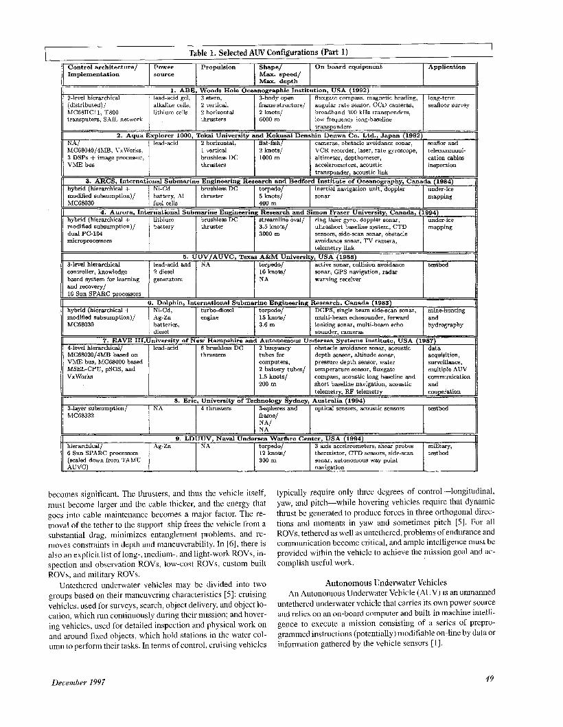
Table 1. Selected AUV Configurations (Part 1) Control architecture/ Power Propulsion Shape/ On-board equipment Implementation source Max. speed/
Application
I M ~ X . depth I 1. ABE, Woods Hole Oceanographic Institution, USA (1992)
2-level hierarchical 1 lead-acid ael. I 3 stern. I 3-bodv oDen I fluxgate comoass. maanetic heading. I loneterm
. I * MC68030 I fuel ceiis
- . L .
(distributed) / alkaline cells. 2 vertical: frame structure/ angular rate sensor. CCD hIC68HCl1, T800 lithium cells 2 horizontal broadband 300 kHz transponders: transputers, SAIL network 1 1 thrusters I :z:/ 1 low frequency long-baseline
transnondem
~~~- I 400 m
I
2. Aqua Explorer 1000, Tokai University and Kokusai Denshin Denwa Co. Ltd., Japan (1992) NAI I lead-acid I 2 horizontal. I flat-ftsh/ I cameras. obstacle avoidance sonar. 1 seaor and
modified subsumption)/ dual PC-104 microprocessors
3-level hierarchical controller, knowledge based system for learning and recovery/
MC68040/4MB, VxWorks? 3 DSPs + image processor, VME bus
battery thruster 3.5 knots/ ultrashort baseline system, CTD mapping 3000 m sensors, side-scan sonar, obstacle
avoidance sonar, TV camera, telemetry link
5. UUV/AUVC, Texas A&M University, USA (1988) lead-acid and NA torpedo/ active sonar, collision avoidance testbed 2 diesel 10 knots/ sonar, GPS navigation, radar generators NA warning receiver
1 vertical 2 knots/ brushless DC 1000 m thrusters
16 Sun S P k C processors I
\'CR recorder, laser, rate gyroscope, altimeter, depthometer, accelerometers, acoustic
telecommuni- cation cables I inspection
I
.,..._ l_) ......
0 3. ARCS, International Submarine Engineering Research and Bedford Institute of Oceanography, Canada (1984)
modi6ei subsumption)/ MC68030
7. EAVE 4-level hierarchical/ MC68020/4MB based on VME bus, MC68000 based MSEL-CPU, pSOS, and VxWorks
hybrid (hierarchical + I brushlessDC I torpedo/ inertial navigation unit, doppler under-ice 11 modified subsum~tion)/ I ::%. A1 thruster 5 h o t s / I sonar I mannine
Ag-Zn' engine 15 Lot,/ multi-bea; echosounder, forward ' and batteries, 3.6 m diesel sounder, cameras
lead-acid 6 brushla8 DC 2 buoyancy obstacle avoidance sonar, xoustic data
"
looking sonar, multi-beam echo hydrography
II1,University of New Hampshire and Autonomous Undersea Systems Institute, USA (1987)
depth sensor, altitude sonar, acquisition, thrusters tubes for computers, pressure depth em", water surveillance, 2 battery tubes/ temperature sensor, fluxgate multiple AUV 1.5 ho t s / compass, acoustic long baseline and communication 200 m short baseline navigation, acoustic and
II I telemetry, FP telemetry 1 cooperation
6 Sun SPARC processors (scaled down from TAMU AUVC)
12 knots/ thermistor, CTD sensors, side-scan testbed 300 m sonar, autonomous way point
navigation
I1 3-laver subsumntion/ I NA I 4 thrusters I 3-snheres and I oDtical sensors. acoustic sensors I =bed
I NA' I 9. LDUUV, Naval Undersea Warfare Center, USA (1994)
hierarchical/ I Ag-Zn I NA I torpedo/ I 3 axis accelerometers, shear probes 1 military,
becomes significant. The thrusters, and thus the vehicle itself, must become larger and the cable thicker, and the energy that goes into cable maintenance becomes a major factor. The re- moval of the tether to the support ship frees the vehicle from a substantial drag, minimizes entanglement problems, and re- moves constraints in depth and maneuverability. In [6], there is also an explicit list of long-, medium-, and light-work ROVs, in- spection and observation ROVs, low-cost ROVs, custom-built ROVs, and military ROVs.
Untethered underwater vehicles may be divided into two groups based on their maneuvering characteristics [5]: cruising vehicles, used for surveys, search, object delivery, and object 10- cation, which run continuously during their mission; and hover- ing vehicles, used for detailed inspection and physical work on and around fixed objects, which hold stations in the water col- umn to perform their tasks. In terms of control, cruising vehicles
typically require only three degrees of control-longitudinal, yaw, and pitch-while hovering vehicles require that dynamic thrust be generated to produce forces in three orthogonal direc- tions and moments in yaw and sometimes pitch [5]. For all ROVs, tethered as well as untethered, problems of endurance and communication become critical, and ample intelligence must be provided within the vehicle to achieve the mission goal and ac- complish useful work.
Autonomous Underwater Vehicles An Autonomous Underwater Vehicle (AUV) is an unmanned
untethered underwater vehicle that carries its own power source and relies on an on-board computer and built-in machine intelli- gence to execute a mission consisting of a series of prepro- grammed instructions (potentially) modifiable on-line by data or information gathered by the vehicle sensors [l].
December 1997 49

L Control architecture/ Implementation
3-level hierarchical/ 4 PCs. Ethernet. dedicated 80C552 micro-controller, CAN network
Power Propulsion Shape/ source Max. speed/
Max. depth 10. Martin, Maridan ApS, Denmark, (1995)
pipeline and lead-acid 6 thrusters. flat-fish/ DGPS. tracking systems. leak propane gas 2 5 knots/ detector. low battery detector. cable Stirling generator 100 m multi-beam sonar, CCD camera, inspection.
optical sensors. acoustic link oceanographic service
3-level hierarchical lead-acid 2 main back (distributed) ,’ thrusters, MC6U030,’Sl~fB + FPU, 4 tunnel OS-9; MC6S020, thrusters MCBSHC11F1, DSP 56002
flat-fish/ mnar, long baseline navigation, coastal seabed 2.5 m/s/ acoustic link transducer, and motion and 600 m sensor package, 1 depth cell, environmental
2 echosounders, doppler sonar surveys
for peripherals
I I I I monitor 16. Phoenix, Naval Postgraduate School, USA (1992)
3-level hybrid (hierarchical 1 lead-acid gel 1 2 vertical, I torpedo (4 altitude sonar, collision avoidance I shallow water
I 1 I
-+ subsumption),’ MC68030/2MB, GESPAC, OS-9; Sun SP,4RC, SunOS
MC68030/8MB, VxWorks, VME, Neuron chips, LONTalk Network
hybrid (hierarchical + het erarchical) / MC68040 + FPU, VxWorks, VME
subsumption (state-configured)/ MC 68030/SMB +FPU, OS-9, VME, MC68HCl1, SAIL network
15. OTTER, 3-level hieradncal/ 2 MVME 167 (MC68040), VxWorks MVME 147 (MC68030)
Ag-Zn tkruster mth 5 knots/ sonar, pressure sensor, sonic data gathering servo controlled 600 m speedmeter, altitude sonar, leak rudder and stem plane
detector, CTD sensor, RF modem
13. ODIN 11, University of Hawaii, USA (1995) lead-acid gel S brushless DC closed frame pressure sensor, 3-ams anglelrate testbed
thrusters near-sphere/ sensor, sonic ranging and positioning 2 knots/ system, mechmcal arm 30 m
14. Odyssey 11, Massachusetts Institute of Technology, USA (1993) Ag-Zn 1 thruster mth streamline oval/ altimeter, CTD sensor, acoustic long-range
servo controlled 3 knots/ modem. obstacle avoidance sonar deep sea rudder and 6000 m pinger, side-scan sonar, acoustic survey,
under-ice elevator doppler current proaer, long basehne nawgation, short baseline mapping navigation
Monterey Bay Aquarium Research Institute and Stanford University, USA (1994) Ni-Cd 2 drive thrusters, flat-fish/ stereo CCD camera, fluxgate multi-purpose
6 maneuvenng 4 knots/ compass, 2-ams inclinometer, .?-axis research thrusters 1000 m angle/rate sensor, pressure sensor, testbed
sonic rangmg and positioning system, leak detector, battery
2 transverse, sonar, gyro suite, sector scanner, acoustic navigation, GPS-DGPS-INS
An AUV can be launched from simpler, smaller ships (com- pared to ROV), or even docks or piers, since there is no umbilical cable. This also enables AUV operation at significant distance from a support ship or platform. The operational cost is further reduced since a human operator is not needed.
However, the absence of a human operator dictates that A W operations are limited by its control system, computing, and sens- ing capabilities. The lack of an umbilical cable limits the AUV to its own power source, thus reducing feasible mission duration.
As a result of these limitations, power, navigation, and mis- sion management are three technologies critical for the future use of AUVs. Advances in these technologies will enable AUV designers to meet the following objectives: flexible communica- tion, efficient solution to temporal planning and resource alloca- tion, information integration and recognition in the process of multi-sensor operation, planning for a given task, and adaptation to system and environment changes [3].
mine counter- measures and coastal environmental
i
NA/ Intel 80186,’ZMB + FPU
This article presents a classification of the control architec- tures used for AUVs and a comparative study/table of 25 AUVs, in terms of control architecture, implementation, power source, propulsion, shape, maximum speed, maximum depth, on-board
selected several state-of-the-art AUVs’ control architectures. A new proposed sensor-based embedded control architec- ture--currently in the paper design phase-suitable for real-time navigation, guidance, and control of AUVs concludes the article.
Classification of A W Control Architectures Advances in sensing, control, communicatlons, and comput-
ing technologies have enabled the development of autononious vehicles that perform critical missions in harsh and unforgiving environments. As the coniplexity of missions increases, the de- mands on sensing, computing, communication, and control in- crease. The control architecture for an autonomous underwater
I I
I I equipment, and application [7] This is followed by a review of I
I
L
I I
I
I
Ni-Cd 2 thrusters flat-fish/ ranging sonars, attitude sensors, near-bottom 3 knots/ 50 kHz transponder, 35 mm camera survey
50 IEEE Control Systems
Control architecture/ Power Propulsion Shape/ On-board equipment Implementation source Max. speed/
Max. deDth U
18. PURL, International Submarine Engineering Research and Simon &aser University, Canada (1993) hvbrid (hierarchical + 1 lead-acid I 2 horizontal. I 3 cvlinders in V- I deuth sensor. fluxgate compass. I small area
Application
1 vertical configuration/ thruster. DC servo motors 70 m
2 vertical thrusters, DC servo motors
. - CTD, side-scan sonar
a hydrodynamic fairing/ 0.6 m/s/
bottom search and survey
aliimeter, pitch/roll sensor; battery monitor
” a 19. PURL 11, International Submarine Engineering Research and Simon Fraser University, Canada (1995)
bottom search and survey
II hvbrid (hierarchical + I Gel cells I 2 horizontal. I toruedo within I deuth sensor. fluxcate comuass. I small area
I l oom
modified subsumption)/ PC-l04/80486/2MB + 11 FPU
I ” 2 PEP-9000 VM40 (MC68040), VME,
closed cycle 1 main thruster, torpedo/ depth gauge, bottom profilers, near bottom diesel engine 2 tunnel vertical 3.6 knots/ CTDO sensor, TV camera, INS with survey
thrusters 400 m doppler sonar, transponder link, VxWorks I I radio link I
1 - configured)/ ’ MC68020 GESPAC, OS-9 ll fluxgate compass, pitch and roll
sensom, yaw rate gyro. water speed Bensor, obstacle avoidance sonar and ultra-short and long baseline
1 vertical thruster
characteristics measurements, testbed
3knots/ ’ I 200m I I navigation system
22. Theseus, International Submarine Engineering Research, Canada (1992) ’ hybrid (hierarchical + I Ni-Cd, I brushless DC I torpedo/ I inertial navigation unit with doppler I cable laying
I acoustic telemetry link I
transducers, long baseline acoustic positioning system, compass, inertial navigation systems, obstacle
I sonar; acoustic homing. forward I looking obstacle avoidance sonar, modified subsumption) / MC68030
motor driving a
- missions at abyssal depths
system, a-axis speed sensors, depth sensor, CCD camera. &channel ultrasonic range finder, ultrasonic link
II hvbrid (hierarchical + I Ag-Zn I 3 main. 2 lateral I toruedo/ I CTD sensor, side-scan sonar, I oceanoloeical
design of intelligent AUVs
hkterar&ical)/ custom-made // microprocessors
subsumption (with lead-acid 1 propelling torpedo/ learning capabilities)/ main thruster, 1 knot/ MVME 162-02 (MC68040) 2 vertical, 2 side NA
thrusters
cable laying. depth sensor, fluxgate compass, pitch angle sensor, tachogenerators, underwater sonar range finders inspection
I 24. Twin Burger, University of Tokyo
3-level hierarchical I Ni-Cd I 2 main, I twin rectangular 2 vertical, 1 side hydrodynamic I I thrusters I hulls and
(distributed) / 10 T800/16MB transputers, 4 T425/4MB transputers,
cylinder within frame/ 1 knot/
avoidance sonar, gravity meter I attitude and heading reference
Japan (1992) I research and
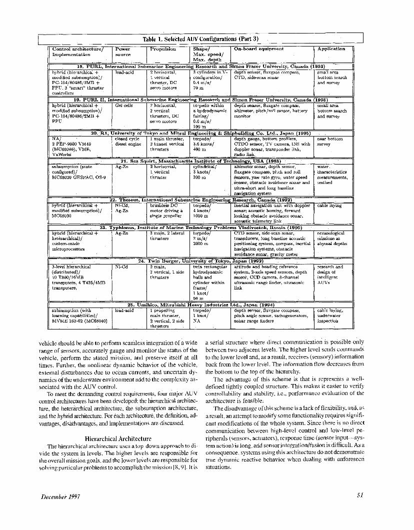
vehicle should be able to perform seamless integration of a wide range of sensors, accurately gauge and monitor the status of the vehicle, perform the stated mission, and preserve itself at all times. Further, the nonlinear dynamic behavior of the vehicle, external disturbances due to ocean currents, and uncertain dy- namics of the underwater environment add to the complexity as- sociated with the AUV control.
To meet the demanding control requirements, four major AUV control architectures have been developed: the herarchcal archtec- ture, the heterarchical architecture, the subsumption architecture, and the hybrid architecture. For each architecture, the definition, ad- vantages, disadvantages, and implementations are discussed.
Hierarchical Architecture The hierarchical architecture uses a top-down approach to di-
vide the system in levels. The higher levels are responsible for the overall mission goals, and the lower levels are responsible for solving particular problems to accomplish the mission [8,9]. It is
a serial structure where direct communication is possible only between two adjacent levels. The higher level sends commands to the lower level and, as a result, receives (sensory) information back from the lower level. The information flow decreases from the bottom to the top of the hierarchy.
The advantage of this scheme is that is represents a well- defined tightly coupled structure. This makes it easier to verify controllability and stability, i.e., performance evaluation of the architecture is feasible.
The disadvantage of this scheme is alack of flexibility, and, as a result, an attempt to modify some functionality requires signifi- cant modifications of the whole system. Since there is no direct communication between high-level control and low-level pe- ripherals (sensors, actuators), response time (sensor input-sys- tem action) is long, and sensor integration/fusion is difficult. As a consequence, systems using this architecture do not demonstrate true dynamic reactive behavior when dealing with unforeseen situations.
December 1997 51
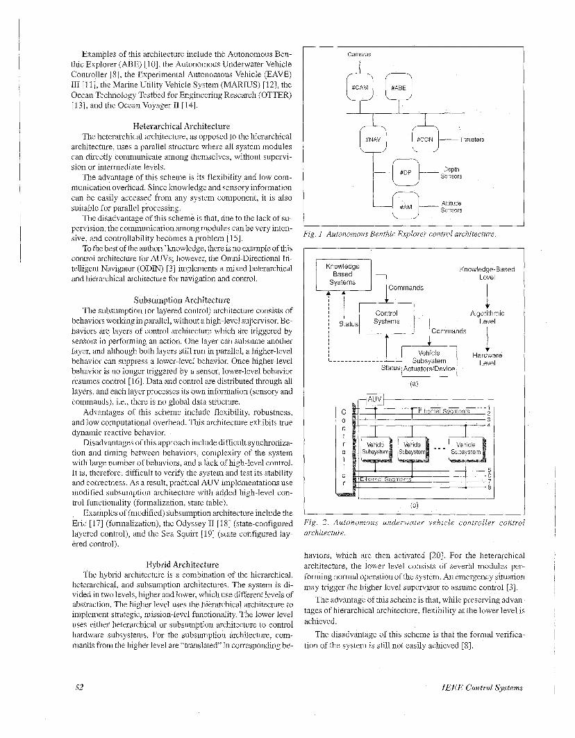
Examples of this architecture include the Autonomous Ben- thic Explorer (ABE) [lo], the Autonomous Underwater Vehicle Controller [8], the Experimental Autonomous Vehicle (EAVE) I11 [ll], the Marine Utility Vehicle System (MARIUS) [12], the Ocean Technology Testbed for Engineering Research (OTTER) [13], and the Ocean Voyager I1 [14].
4 A sysrems
Heterarchical Architecture The heterarchical architecture, as opposed to the hierarchical
architecture, uses a parallel structure where all system modules can directly communicate among themselves, without supervi- sion or intermediate levels.
The advantage of this scheme is its flexibility and low com- munication overhead. Since knowledge and sensory information can be easily accessed from any system component, it is also suitable for parallel processing
The disadvantage of this scheme is that, due to the lack of su- pervision, the communication among modules can be very inten- sive, and controllability becomes a problem [15].
To the best of the authors’knowledge, there is no example of th~s control archtecture for AUVs, however, the Omn-Directional In- telligent Navigator (ODIN) [3] implements a mixed heterarchical and hierarchical architecture €or navigation and control.
Commands
Subsumption Architecture The subsumption (or layered control) architecture consists of
behaviors working in parallel, without a high-level supervisor. Be- haviors are layers of control architecture which are triggered by sensors in performing an action. One layer can subsume another layer, and although both layers still run in parallel, a higher-level behavior can suppress a lower-level behavior. Once higher-level behavior i s no longer tnggered by a sensor, lower-level behavior resumes control [ 161 Data and control are distributed through all layers, and each layer processes its own mformation (sensory and commands), i.e., there is no global data structure.
Advantages of this scheme include flexibility, robustness, and low computational overhead This architecture exhibits true dynamic reactive behavior.
Disadvantages of this approach include difficult synchroniza- tion and timing between behaviors, complexity of the system with large number of behaviors, and a lack of high-level control It is, therefore, difficult to verify the system and test its stability and correctness. As a result, practical AUV implementations use modified subsumption architecture with added high-level con- trol functionality (fonnalization, state table).
Examples of (modified) subsumption architecture include the Eric [ 171 (formalization), the Odyssey I1 [18] (state-configured layered control), and the Sea Squirt [19] (state configured lay- ered control).
I
I
Hybrid Architecture The hybrid architecture is a combmation of the hierarchical,
heterarchical, and subsumption architectures. The system is di- vided in two levels, higher and lower, which use different levels of abstraction. The higher level uses the hierarchical architecture to implement strategic, mission-level functionality. The lower level uses either heterarchical or subsumption architecture to control hardware subsystems. For the subsumption architecture, com- mands from the higher level are “translated” in corresponding be-
v
Control Algorithmic
Cameras
I Status I
Attitude Sensors
Systems __ Level Commands
Fig. I Autonomous Benthic Explorer control architectum.
k I I
Knowledge 1 Knowledae-Based Based - .
I I
V
Vehicle Hardware
C 0 n t r
I I e r
0
Subsystem Status Actuators/Device
1 2
Level
5 6 7 8
Fig. 2 . Autonomous underwater vehicle controller control architecture.
haviors, which are then activated [20]. For the heterarchical architecture, the lower level consists of several modules per- forming normal operation of the system. An emergency situation may trigger the higher level supervisor to assume control [3]
The advantage of this scheme is that, while preserving advan- tages of hierarchical architecture, flexibility at the lower level is achieved.
The disadvantage of this scheme is that the formal verifica- tion of the system is still not easily achieved [8].
52 IEEE Control SyStQm.5
Socialization Level 1 (G) 1 Exdoration Level
I I
Preservation Level
r=q(E)( Collisions
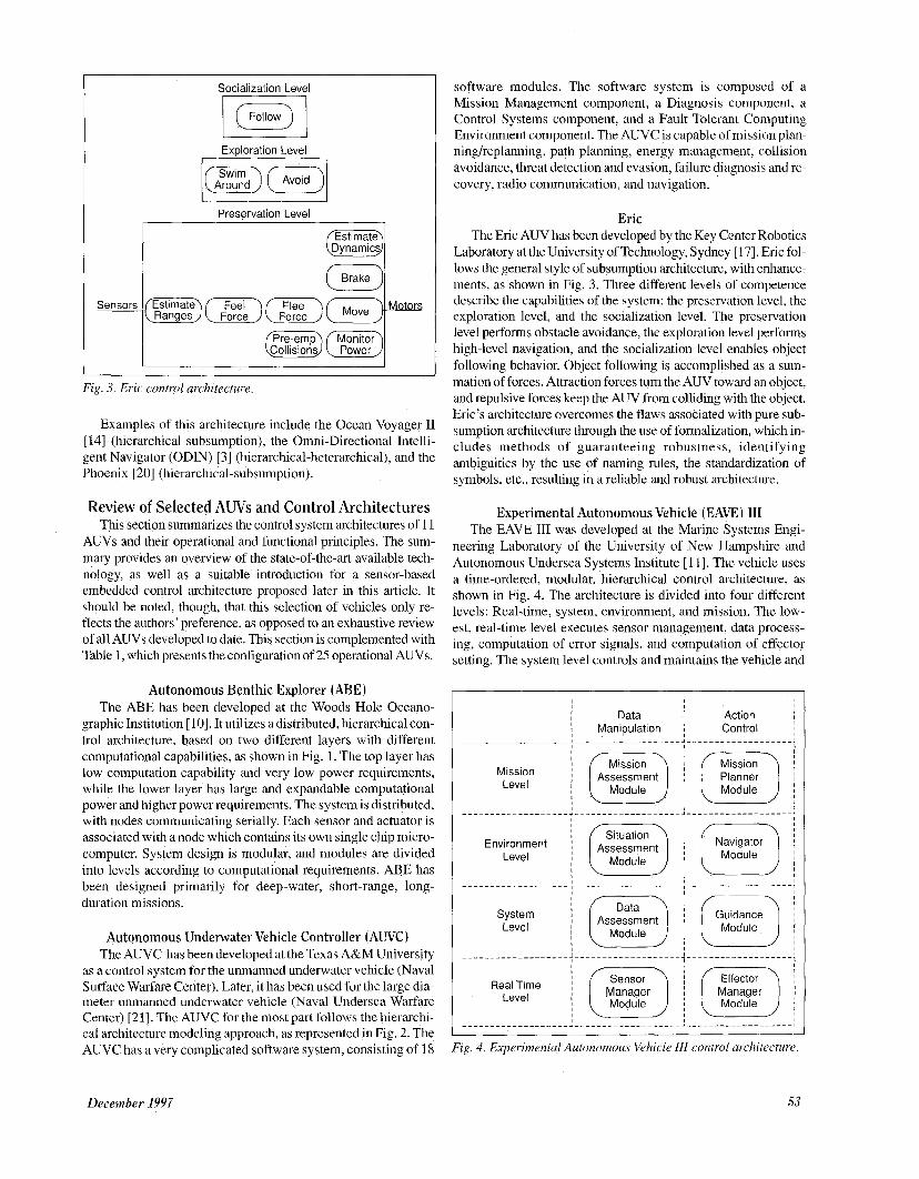
Fig. 3. Eric control architecture.
Examples of this architecture include the Ocean Voyager I1 [ 141 (hierarchical-subsumption), the Omni-Directional Intelli- gent Navigator (ODIN) [3] (hierarchical-heterarchical), and the Phoenix [20] (hierarchical-subsumption).
Review of Selected AWs and Control Architectures This section summarizes the control system architectures of 11
AUVs and their operational and functional principles. The sum- mary provides an overview of the state-of-the-art available tech- nology, as well as a suitable introduction for a sensor-based embedded control architecture proposed later in this article. It should be noted, though, that this selection of vehicles only re- flects the authors’ preference, as opposed to an exhaustive review of all AUVs developed to date. This section is complemented with Table 1, which presents the configuration of 25 operational AUVs.
Autonomous Benthic Explorer (ABE) The ABE has been developed at the Woods Hole Oceano-
graphic Institution [lo]. It utilizes a distributed, hierarchical con- trol architecture, based on two different layers with different computational capabilities, as shown in Fig. 1. The top layer has low computation capability and very low power requirements, while the lower layer has large and expandable computational power and higher power requirements. The system is distributed, with nodes communicating serially. Each sensor and actuator is associated with a node which contains its own single chip micro- computer. System design is modular, and modules are divided into levels according to computational requirements. ABE has been designed primarily for deep-water, short-range, long- duration missions.
Autonomous Underwater Vehicle Controller (AWC) The AUVC has been developed at the Texas A&M University
as a control system for the unmanned underwater vehicle (Naval Surface Warfare Center). Later, it has been used for the large dia- meter unmanned underwater vehicle (Naval Undersea Warfare Center) [21]. The AUVC for the most part follows the hierarchi- cal architecture modeling approach, as represented in Fig. 2. The AUVC has a very complicated software system, consisting of 18
software modules. The software system is composed of a Mission Management component, a Diagnosis component, a Control Systems component, and a Fault Tolerant Computing Environment component. The AUVC is capable of mission plan- ning/replanning, path planning, energy management, collision avoidance, threat detection and evasion, failure diagnosis and re- covery, radio communication, and navigation.
Eric The Eric AUV has been developed by the Key Center Robotics
Laboratory at the University of Technology, Sydney [ 171. Eric fol- lows the general style of subsumption architecture, with enhance- ments, as shown in Fig. 3. Three different levels of competence describe the capabilities of the system: the preservation level, the exploration level, and the socialization level. The preservation level performs obstacle avoidance, the exploration level performs high-level navigation, and the socialization level enables object following behavior. Object following is accomplished as a sum- mation of forces. Attraction forces turn the AUV toward an object, and repulsive forces keep the AUV from colliding with the object. Eric’s architecture overcomes the flaws associated with pure sub- sumption architecture through the use of formalization, which in- cludes methods of guaranteeing robustness, identifying ambiguities by the use of naming rules, the standardization of symbols, etc., resulting in a reliable and robust architecture.
Experimental Autonomous Vehicle (EAVE) I11 The EAVE I11 was developed at the Marine Systems Engi-
neering Laboratory of the University of New Hampshire and Autonomous Undersea Systems Institute [ 111. The vehicle uses a time-ordered, modular, hierarchical control architecture, as shown in Fig. 4. The architecture is divided into four different levels: Real-time, system, environment, and mission. The low- est, real-time level executes sensor management, data process- ing, computation of error signals, and computation of effector setting. The system level controls and maintains the vehicle and
I Module Module Level I
Module Level
Fig. 4. Experimental Autonomous Vehicle 111 control architecture.
December 1997 53
determines how accurately the desired path has been followed. The environment level deals with the vehicle's physical environ- ment. The mission level is a high-level planner that handles aspects particular to the mission and the tasks to be accom- plished. The control system design allows additional sensors and software to augment the system The EAVE open space-frame design makes it an extremely flexible and adaptable testbed.
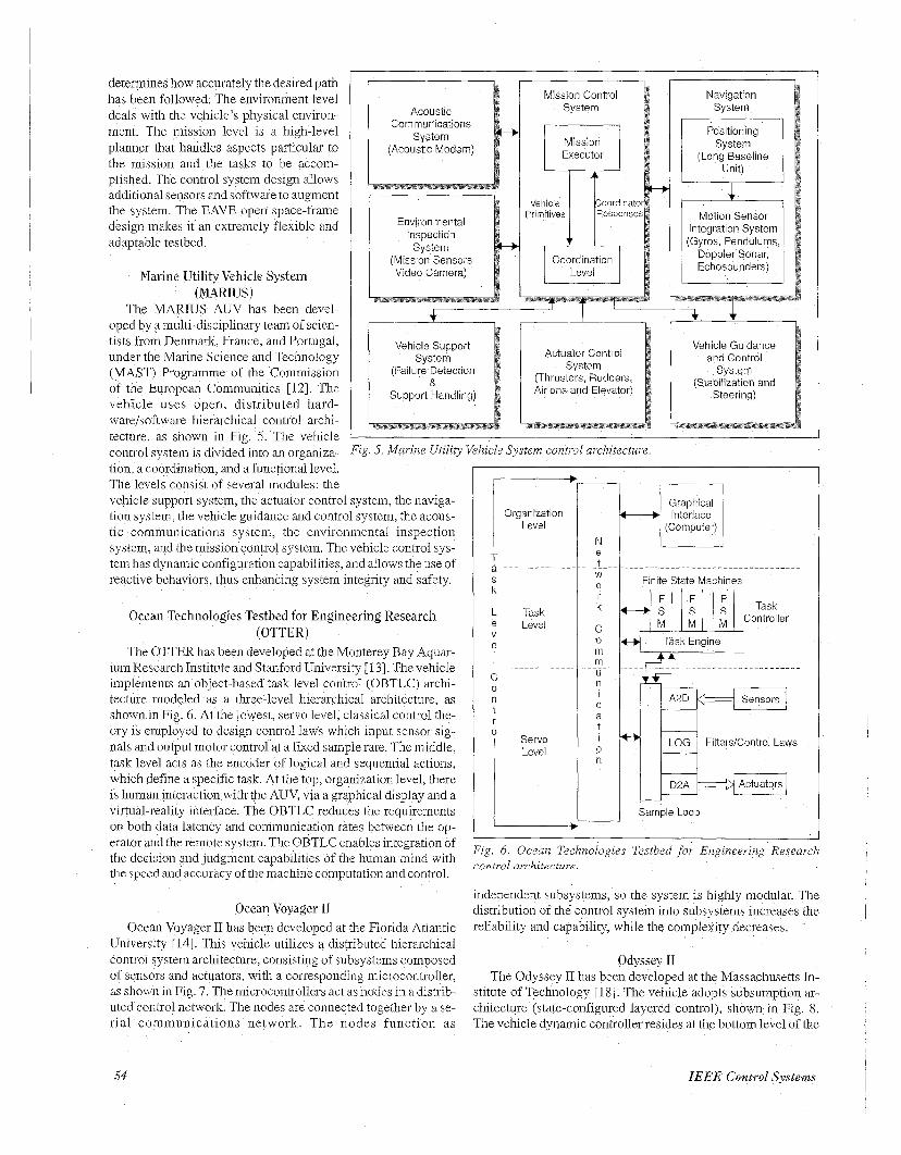
Marine Utility Vehicle System (MARIUS)
The MARIUS AUV has been devel- oped by a multi-disciplinary team of scien- tists from Denmark, France, and Portugal, under the Marine Science and Technology (MAST) Programme of the Commission of the European Communities [12] The vehicle uses open, distributed hard- wae/software hierarchical control archi- tecture, as shown in Fig 5. The vehicle
Communications
(Acoustic Modem)
Environmental Inspection System
(Mission Sensors Video Camera)
Mission Control System
Mission Executor
Vehicle Primitives
Navigation System
System (Long Baseline
Motion Sensor Integration System (Gyros, Pendulums,
Doppler Sonar, Echosounders)
I I
I , + + Vehicle Guidance
(Thrusters, Rudders, (Stabilization and Airlons and Elevator)
Actuator Control
(Failure Detection
Support Handling)
tion, a coordination, and a functional level. The levels consist of several modules the vehicle support system, the actuator control system, the naviga- tion system, the vehicle guidance and control system, the acous- tic communications system, the environmental inspection system, and the mission control system. The vehicle control sys- tem has dynamic configuration capabilities, and allows the use of reactive behaviors, thus enhancing system integrity and safety.
Ocean Technologies Testbed for Engineering Research (OTTER)
The OTTER has been developed at the Monterey Bay Aqua- ium Research Institute and Stanford University [ 131. The vehicle implements an object-based task level control (OBTLC) archi- tecture modeled as a three-level hierarchical architecture, as shown in Fig. 6. At the lowest, servo level, classical control the- ory is employed to design control laws which input sensor sig- nals and output motor control at a fixed sample rate. The middle, task level acts as the encoder of logical and sequential actions, which define a specific task. At the top, organization level, there is human interaction with the AUV, via a graphical display and a virtual-reality interface. The OBTLC reduces the requirements on both data latency and communication rates between the op- erator and the remote system. The OBTLC enables integration of the decision and judgment capabilities of the human mind with the speed and accuracy of the machine computation and control.
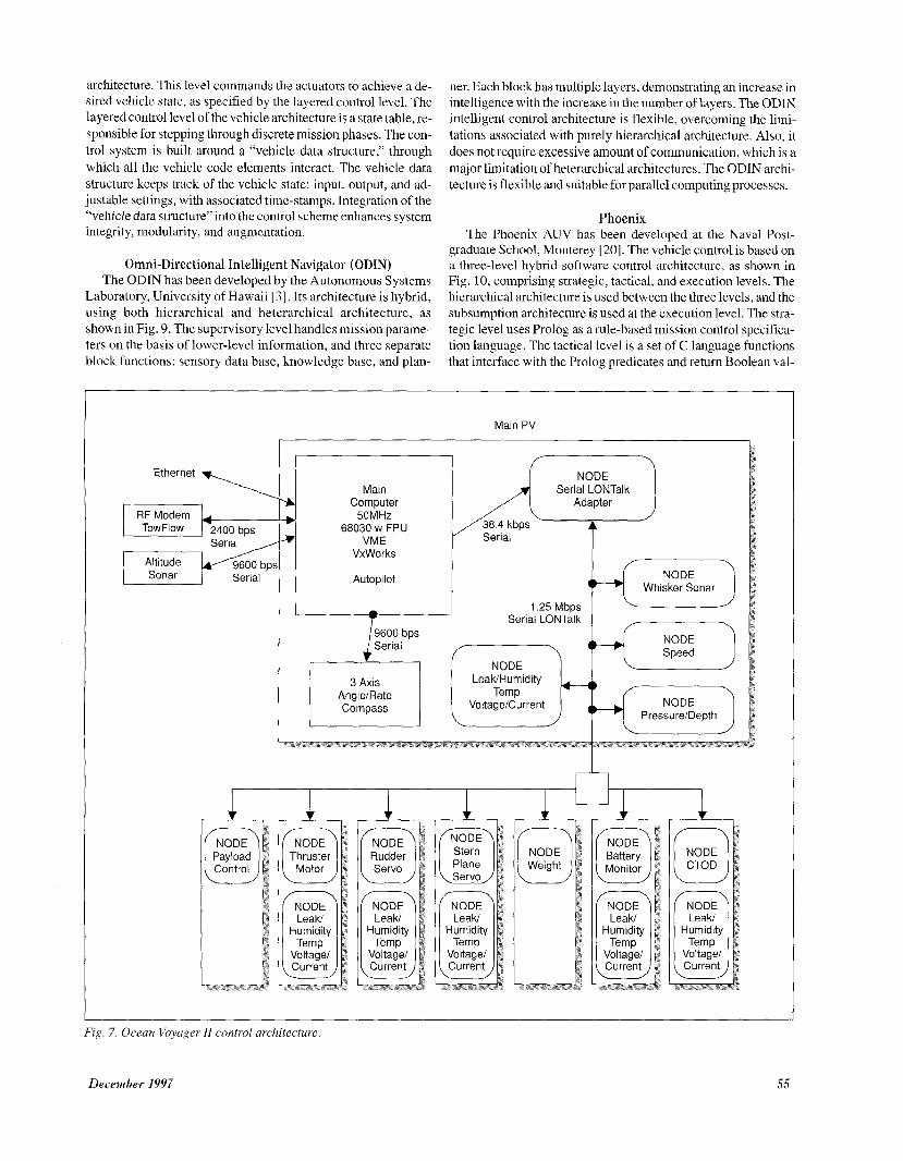
Ocean Voyager 11 Ocean Voyager I1 has been developed at the Florida Atlantic
University [ 141. This vehicle utilizes a distributed hierarchical control system architecture, consisting of subsystems composed of sensors and actuators, with a corresponding microcontroller, as shown in Fig. 7. The microcontrollers act as nodes in a distrib- uted control network. The nodes are connected together by a se- rial communications network. The nodes function as
zg. 6 . Ocean Technologies Testbed for Engineering Research control avchitecture
independent subsystems, so the system is highly modular. The distribution of the control system into subsystems increases the reliability and capability, while the complexity decreases.
Odyssey I1 The Odyssey I1 has been developed at the Massachusetts In-
stitute of Technology [18]. The vehicle adopts subsumption ai- chitecture (state-configured layered control), shown in Fig. 8. The vehicle dynamic controller resides at the bottom level of the
54 IEEE Control Systems
architecture. This level commands the actuators to achieve a de- sired vehicle state, as specified by the layered control level. The layered control level of the vehicle architecture is a state table, re- sponsible for stepping through discrete mission phases. The con- trol system is built around a “vehicle data structure,” through which all the vehicle code elements interact. The vehicle data structure keeps track of the vehicle state: input, output, and ad- justable settings, with associated time-stamps. Integration of the “vehicle data structure” into the control scheme enhances system integrity, modularity, and augmentation.
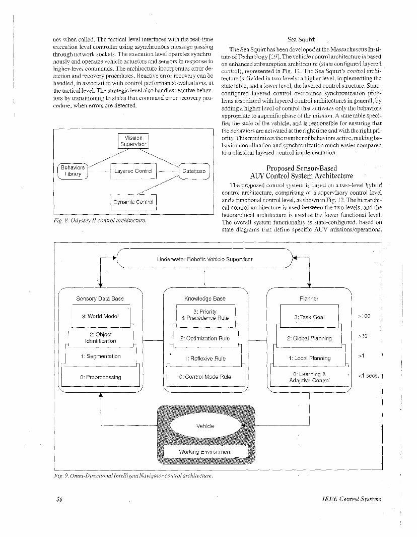
Omni-Directional Intelligent Navigator (ODIN) The ODIN has been developed by the Autonomous Systems
Laboratory, University of Hawaii [3]. Its architecture is hybrid, using both hicrarchical and heterarchical architecturc, as shown in Fig. 9. The supervisory level handles mission parame- ters on the basis of lower-level information, and three separate block functions: sensory data base, knowledge base, and plan-
ner. Each block has multiple layers, demonstrating an increase in intelligence with the increase in the number of layers. The ODIN intelligent control architecture is flexible, overcoming the limi- tations associated with purely hierarchical architecture. Also, it does not require excessive amount of communication, which is a major limitation of heterarchical architectures. The ODIN archi- tecture is flexible and suitable for parallel computing processes.
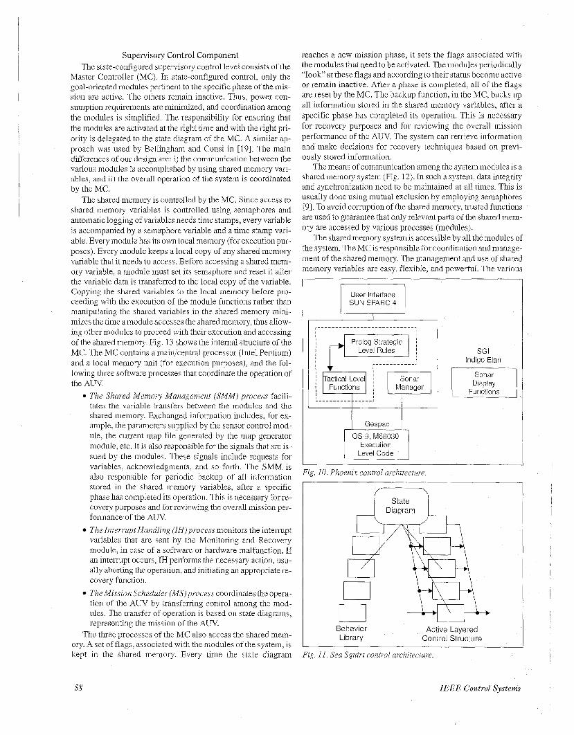
Phoenix The Phoenix AUV has been developed at the Naval Post-
graduate School, Monterey [20]. The vehicle control is based on a three-level hybrid software control architecture, as shown in Fig. 10, comprising strategic, tactical, and execution levels. The hierarchical architecture i5 used belween the three levels, arid the subsumption architecture is used at the execution level. The stra- tegic level uses Prolog as a rule-based mission control specifica- tion language. The tactical level is a set of C language functions that interface with the Prolog predicates and retum Boolean val-
--------.I, Ethernet
RF Modem
9600 bps Serial
Main PV
Main Computer
50MHZ 68030 w FPU
VME
Serial LONTalk
38.4 kbps Serial
VxWorks
Autopilot Whisker Sonar
Serial LONTalk ,-- --.
Leak/ Humidity
Voltage/ Current
Fig. 7. Ocean Voyager I1 control architecture,
December 1997 55
ues when called. The tactical level interfaces with the real-time execution level controller using asynchronous message passing through network sockets. The execution level operates synchro- nously and operates vehicle actuators and sensors in response to higher-level commands. The architecture incorporates error de- tection and recovery procedures. Reactive error recovery can be handled, in association with control performance evaluations, at the tactical level. The strategic level also handles reactive behav- iors by transitioning to states that command error recovery pro- cedure, when errors are detected.
Mission Supervisor
Database
Dynamic Control E3 Fig. 8. Odyssey II control architecture.
Sea Squirt
The Sea Squirt has been developed at the Massachusetts Insti- tute of Technology [ 191. The vehicle control architecture is based oii eidianced subsumption architecture (state configured layered control), represented in Fig 11. The Sea Squirt’s control archi- tecture is divided in two levels a higher level, implementing the state table, and a lower level, the layered control structure. State- configured layered control overcomes synchronization prob- lems associated with layered control architectures in general, by adding a higher level of control that activates only the behaviors appropnate to a specific phase of the mission A state table speci- fies the state of the vehicle, and is responsible for ensuring that the behaviors are activated at the right time and with the right pri- onty. This minimizes the number of behaviors active, making be- havior coordination and synchronization much easier compared to a classical layered control implementation
Proposed Sensor-Based A W Control System Architecture
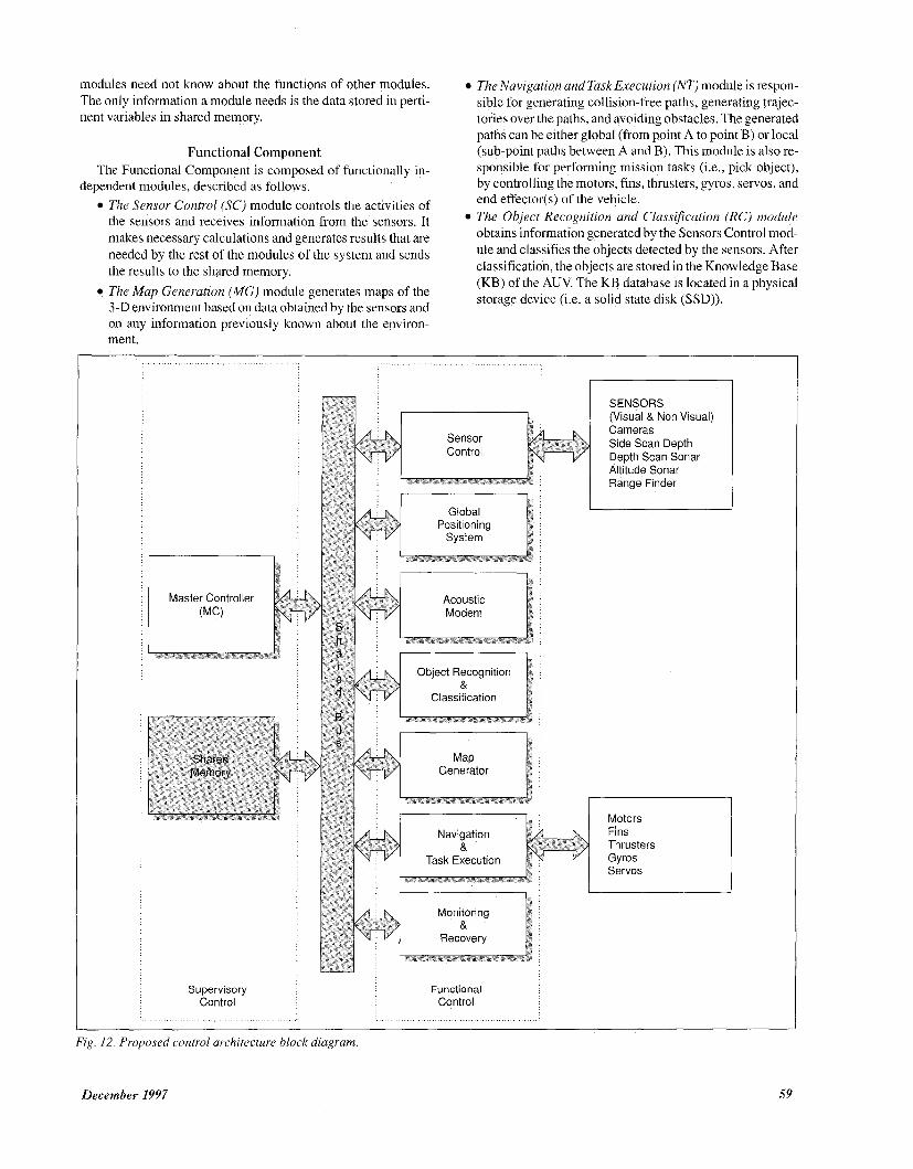
The proposed wntrol system is bdsecl on a two-level hybrid control architecture, comprising of a supervisory control level and a functional control level, as shown in Fig. 12 The hierarchi- cal control architecture is used between the two levels, and the heterarchical architecture is used at the lower functional level. The overall system functionality is state-configured, based on state diagrams that define specific AUV missions/operations.
Underwater Robotic Vehicle Supervisor
Sensory Data Base t 1
3: World Model - -
2: Object Identification -
1 : Segmentation - -
0: Preprocessing
Knowledge Base
3: Priority 1 & Precedence Rule
2: Optimization Rule i , ! L 2: Optimization Rule i , ! L 1 : Reflexive Rule
0: Control Mode Rule
Planner
m 3: Task Goal L
2 Global Planning
1 Local Planning
0 Learning & Adaptive Control
-
> I 00
.>I 0
>1
secs. 1
Fig 9 Omni-Directional~ntelligent Navigator control architecture
56 IEEE Control Syx%tru
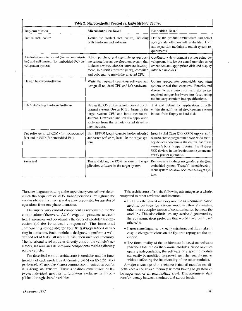
Table 2. Microcontroller Control vs. Embedded-PC Control
Implementation
Define architecture
Assemble remote hosted (for microcontrol ler) and self-hosted (for embedded-PC) de velopment system
Design hardware/software
Integrate/debug hardwarehoftware
Put software in EPROM (for microcontrol ler) and in SSD (for embedded-PC)
Final test
Microcontroller-Based
Define the product architecture, including both hardware and software.
Select, purchase, and assemble an appropri- ate remote-hosted development system thai includes a workstation for software develop- ment, in-circuit emulator (ICE), compiler and debugger to match the selected CPU.
Write the required operating software and design all required CPU and I/O hardware.
Debug the OS on the remote-hosted devel- opment system. Use an ICE to bring up the target system CPU and basic system re- sources. Download and test the application software from the remote-hosted develop- ment system.
Burn EPROM, equivalent to the downloaded and tested software, install in the target sys- tem.
Test and debug the ROM version of the ap- plication software in the target system.
The state diagram residing at the supervisory control level deter- mines the sequence of AUV tasks/operations throughout the various phases of a mission and is also responsible for transfer of operations from one phase to another.
The supervisory control component is responsible for the coordination of the overall AUV navigation, guidance, and con- trol. It monitors and coordinates the order of module task exe- cution (of the functional component). The functional component is responsible for specific tasks/operations occur- ring in a mission. Each module is designed to perform a well- defined set of tasks; all modules have their own local memory. The functional level modules directly control the vehicle’s ac- tuators, sensors, and all hardware components residing directly on the vehicle.
The described control architecture is modular, and the func- tionality of each module is determined based on specific tasks performed. All modules share a common communication bus for data storage and retrieval. There is no direct communication be- tween individual modules. Information exchange is accom- plished through shared variables.
~~ ~
Embedded-Based
Define the product architecture and seleci appropriate off-the-shelf embedded CPL and expansion modules to match system re- auirements.
~ ~~
Configure a development system using de- velopment kits for the actual modules to be embedded and appropriate disk and display interface modules.
Obtain appropriate compatible operating system or real time executive, libraries and drivers. Write required software, design any required unique hardware interfaces using the industrv standard bus sDecifications.
Test and debug the application directly within the self-hosted development system booted from floppy or hard disk.
Install Solid State Disk (SSD) support soft- ware to create programmed byte-wide mem- ory devices containing the equivalent of the system’s boot floppy diskette. Install these SSD devices in the development system and verifv Droper oDeration.
Remove any modules not needed in the final embedded system. The self-hosted develop- ment system has now become the target sys- tem.
This architecture offers the following advantages as a whole,
It utilizes the shared memory module as a communication medium between the various modules, thus eliminating other more complex means of communication between the modules. This also eliminates any overhead generated by the communication protocols that would have been used otherwise.
It uses state diagrams to specify missions, and thus makes it easy to change missions on the fly, or to reprogram the op- eration. The functionality of the architecture is based on software functions that run on the various modules. Since modules operate independently, the software of a specific module can easily be modified, improved, and changed altogether without affecting the functionality of the other modules.
A major advantage of this scheme i s that all modules can di- rectly access the shared memory without having to go through the supervisor or an intermediate level. This minimizes data transfer latency between modules and across levels.
compared to other reviewed architectures.
December 1997 57
Supervisory Control Component The state-configured supervisory control level consists of the
Master Controller (MC). In state-configured control, only the goal-oriented modules pertinent to the specific phase of the mis- sion are active. The others remain inactive. Thus, power con- sumption requirements are minimized, and coordination among the modules is simplified. The responsibility for ensuring that the modules are activated at the right time and with the right pri- ority is delegated to the state diagram of the MC. A similar ap- proach was used by Bellingham and Consi in [19]. The main differences of our design are: i) the communication between the various modules is accomplished by using shared memory vari- ables, and ii) the overall operation of the system is coordinated by the MC.
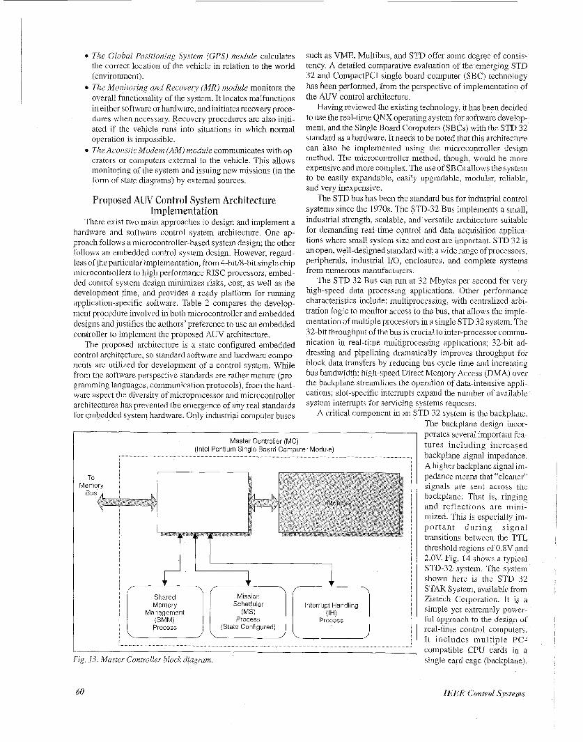
The shared memory is controlled by the MC. Since access to shared memory variables is controlled using semaphores and automatic logging of variables needs time stamps, every variable is accompanied by a semaphore variable and a time stamp vari- able. Every module has its own local memory (for execution pur- poses). Every module keeps a local copy of any shared memory variable that it needs to access. Before accessing a shared mem- ory variable, a module must set its semaphore and reset it after the variable data is transferred to the local copy of the variable. Copying the shared variables to the local memory before pro- ceeding with the execution of the module functions rather than manipulating the shared variables in the shared memory mini- mizes the time a module accesses the shared memory, thus allow- ing other modules to proceed with their execution and accessing of the shared memory. Fig. 13 shows the intemal structure of the MC. The MC contains a main/central processor (Intel Pentium) and a local memory unit (for execution purposes), and the fol- lowing three software processes that coordinate the operation of the AUV.
* The Shared Memory Management (SMM) process facili- tates the variable transfers between the modules and the shared memory. Exchanged information includes, for ex- ample, the parameters supplied by the sensor control mod- ule, the current map file generated by the map generator module, etc. It is also responsible for the signals that are is- sued by the modules. These signals include requests for variables, acknowledgments, and so forth. The SMM is also responsible for periodic backup of all information stored in the shared memory variables, after a specific phase has completed its operation. This is necessary for re- covery purposes and for reviewing the overall mission per- formance of the AUV. The Interrupt Handling (IHjprocess monitors the interrupt variables that are sent by the Monitoring and Recovery module, in case of a software or hardware malfunction. If an interrupt occurs, IH performs the necessary action, usu- ally aborting the operation, and initiating an appropriate re- covery function. The Mission Scheduler (MS)process coordinates the opera- tion of the AUV by transferring control among the mod- ules. The transfer of operation is based on state diagrams, representing the mission of the AUV.
The three processes of the MC also access the shared mem- ory. A set of flags, associated with the modules of the system, is kept in the shared memory. Every time the state diagram
58
reaches a new mission phase, it sets the flags associated with the modules that need to be activated. The modules periodically “look” at these flags and according to their status become active or remain inactive. After a phase is completed, all of the flags are reset by the MC. The backup function, in the MC, backs up all information stored in the shared memory variables, after a specific phase has completed its operation. This is necessary for recovery purposes and for reviewing the overall mission performance of the AUV. The system can retrieve information and make decisions for recovery techniques based on previ- ously stored information.
The means of communication among the system modules is a shared memory system (Fig. 12). In such a system, data integrity and synchronization need to be maintained at all times. This is usually done using mutual exclusion by employing semaphores [9]. To avoid corruption of the shared memory, trusted functions are used to guarantee that only relevant parts of the shared mem- ory are accessed by various processes (modules).
The sharedmemory system is accessible by all the modules of the system. The MC is responsible for coordination and manage- ment of the shared memory. The management and use of shared memory variables are easy, flexible, and powerful. The various
User Interface SUN SPARC 4
Prolog Strategic 1 1 Level Rules I I
1 GesDac 1 OS-9, M68030
Execution Level Code
SGI Indigo Elan
Sonar Display
Functions
Fig. 10. Phoenix control architecture.
Behavior Active Layered Library Control Structure
Fig. I I . Sea Squirt control architecture.
IEEE Control Systems
modules need not know about the functions of other modules. The only information a module needs is the data stored in perti- nent variables in shared memory.
The Navigation and Task Execution (NTJ module is respon- sible for generating collision-free paths, generating trajec- tories over the paths, and avoiding obstacles. The generated paths can be either global (from point A to point B) or local (sub-point paths between A and B). This module is also re- sponsible for performing mission tasks (i.e., pick object), by controlling the motors, fins, thrusters, gyros, servos, and end effector(s) of the vehicle.
obtains information generated by the Sensors Control mod- ule and classifies the objects detected by the sensors. After classification, the objects are stored in the Knowledge Base (KB) of the AUV. The KB database is located in a physical storage device (i.e. a solid state disk (SSD)).
Functional Component The Functional Component is composed of functionally in-
The Sensor Control (SC) module controls the activities of
makes necessary calculations and generates results that are needed by the rest of the modules of the system and sends the results to the shared memory. The Map Generation ( M G ) module generates maps of the 3-D environment based on data obtained by the sensors and
dependent modules, described as follows.
the Sensors and receives information from the sensors. It The Object Recognition and (Rc)
on any information previously known about the environ- ment.
Master Controller
Shared Memory
Supervisory Control
SENSORS (Visual & Non Visual) Cameras Side Scan Depth rlnnth Cnqn 9nn.lr
I
Classification
I
I
Fins Thrus Gyros Servos
Functional Control
ters
- Fig. 12. Proposed control architecture block diagram.
December 1997 59
e The Global Positioning System ( G P S ) module calculates the correct location of the vehicle in relation to the world (environment).
.a The Monitoring and Recovery (MR) module monitors the overall functionality of the system. It locates malfunctions in either software or hardware, and initiates recovery proce- dures when necessary. Recovery procedures are also initi- ated if the vehicle runs into situations in which normal operation is impossible.
8 The Acoustic Modem (AM) module communicates with op- erators or computers external to the vehicle. This allows monitoring of the system and issuing new missions (in the form of state diagrams) by external sources.
Proposed AW Control System Architecture Implementation
There exist two main approaches to design and implement a hardware and software control system architecture. One ap- proach follows a microcontroller-based system design; the other follows an embedded control system design. However, regard- less of the particular implementation, from 4-bit/8-bit single chip microcontrollers to high performance RISC processors, embed- ded control system design minimizes risks, cost, as well as the development time, and provides a ready platform for running application-speci€ic software. Table 2 compares the develop- ment procedure involved in both microcontroller and embedded designs and justifies the authors’ preference to use an embedded controller to implement the proposed AUV architecture.
The proposed architecture IS a state-configured embedded control architecture, so standard software and hardware compo- nents are utilized for development of a control system. While from the software perspective standards are rather mature (pro- gramming languages, communication protocols), from the hard- ware aspect the diveraity of microprocessor and microcontroller architectures has prevented the emergence of any real standards for embedded system hardware. Only industrial computer buses
such as VME, Multibus, and STD offer some degree of consis- tency. A detailed comparative evaluation of the emerging STD 32 and CompactPC1 single board computer (SBC) technology has been performed, from the perspective of implementation of the AUV control architecture.
Having reviewed the existing technology, it has been decided to use the real-time QNX operating system for software develop- ment, and the Single Board Computers (SBCs) with the STD 32 standard as a hardware. It needs to be noted that this architecture can also be implemented using the microcontroller design method. The microcontroller method, though, would be more expensive andmore complex. The use of SBCs allows the system to be easily expandable, easily upgradable, modular, reliable, and very inexpensive.
The STD bus has been the standard bus for industrial control systems since the 1970s. The STD-32 Bus implements a small, industrial strength, scalable, and versatile architecture suitable for demanding real-time control and data acquisition apphca- tions where small system size and cost are important. STD 32 is an open, well-designed standard with a wide range of processors, peripherals, industrial I/O, enclosures, and complete systems from numerous manufacturers.
The STD 32 Bus can run at 32 Mbytes per second for very high-speed data processing applications. Other performance charactenstics include: multiprocessing, with centralized arbi- tration logic to monitor access to the bus, that allows the imple- mentation of multiple processors in a single STD 32 system. The 32-bit throughput ofthe bus is crucial to inter-processor commu- nication in real-time multiprocessing applications; 32-bit ad- dressing and pipelining dramatically improves throughput for block data transfers by reducing bus cycle time and increasing bus bandwidth; high-speed Direct Memory Access (DMA) over the backplane streamlines the operation of data-intensive appli- cations; slot-specific interrupts expand the number of available system interrupts for servicing systems requests.
A critical component in an STD 32 system is the backplane.
To Memory
Master Controller (MG) (Intel Pentium Single Board Computer Module)
I I L
Shared Memory
Management
Process
Mission Scheduler
Process (State Configured)
Interrupt Handling
Process
I 1nterru;;Pndling
Process
Fig. 13 Master Controller block diagram.
60
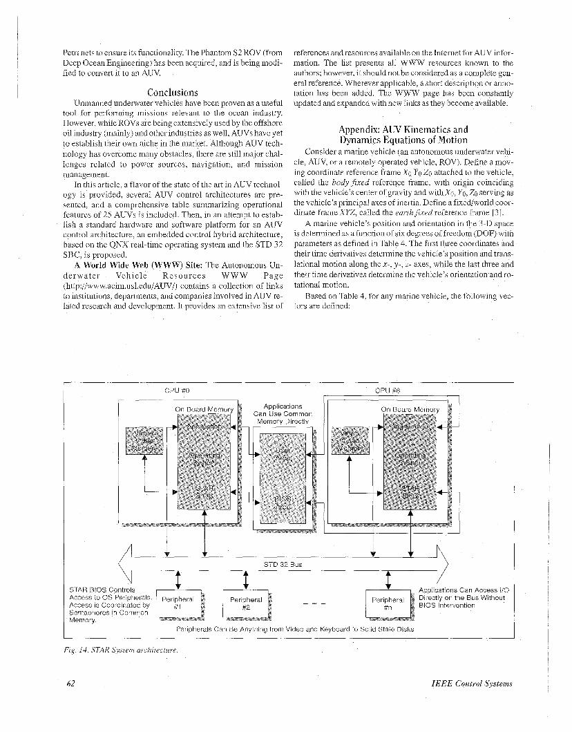
The backplane design incor- porates severa1 important fea- tures Including increased backplane signal impedance. A higher backplane signal im- pedance means that “cleaner” signals are sent across the backplane. That is , ringing and reflections are mini- mized. This is especially im- portant during s igna l transitions between the TTL threshold regions of 0.8V and 2.OV. Fig. 14 sho~7s a typical STD-32 system. The system shown here is the STD 32 STAR System, available from Ziatech Coiporation. It i s a simple yet extremely power- ful approach to the design of real-time control computers. It includes multiple PC- compatible CPU cards in a single card cage (backplane).
IEEE Control Systems
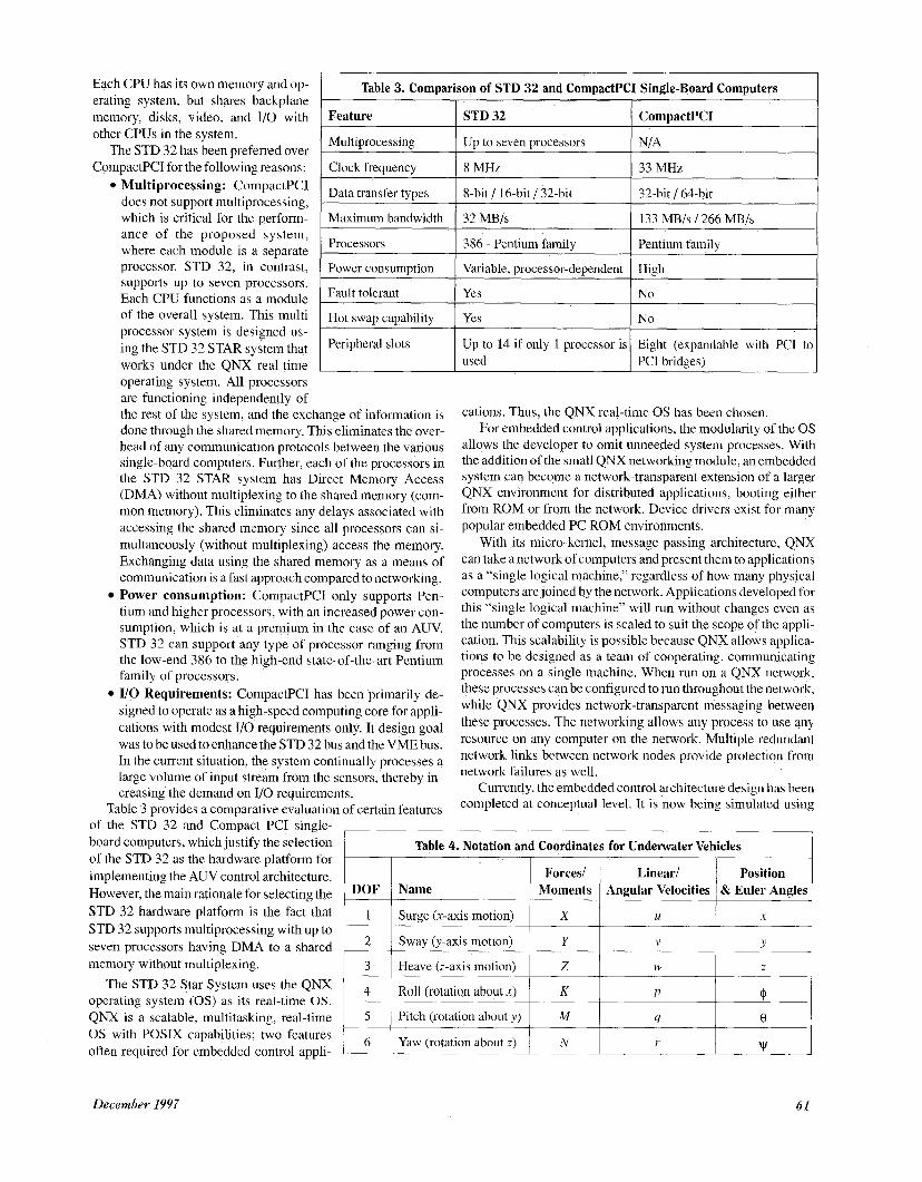
Table 3. Comparison of STD 32 and CompactPCI Single-Board Computers
memory, disks, video, and 1/0 with STD 32 CompactPCI
Each CPU has its own memory and op- erating system, but shares backplane
other CPUs in the system.
CompactPC1 for the following reasons: 8 MHz 33 MHz
Multiprocessing Up to seven processors The STD 32 has been preferred over
ance of the proposed system, where each module is a separate
which is critical for the perfom- 1 Maximum bandwidth 1 32 MB/s 1 133 MBIs 1266 MB/s I I
Processors 386 - Pentium family Pentium family I
Power consumption
Fault tolerant
Hot swap capability
Peripheral slots
processor. STD 32, in contrast, supports up to seven processors. Each CPU functions as a module of the overall system. This multi processor system is designed us- ing the STD 32 STAR system that works under the QNX real-time
Variable, processor-dependent High
Yes No
Yes No
Up to 14 if only 1 processor is Eight (expandable with PCI to used PCI bridges)
operating system. All processors are functioning independently of the rest of the system, and the exchange of information is done through the shared memory. This eliminates the over- head of any communication protocols between the various single-board computers. Further, each of the processors in the STD 32 STAR system has Direct Memory Access (DMA) without multiplexing to the shared memory (com- mon memory). This eliminates any delays associated with accessing the shared memory since all processors can si- multaneously (without multiplexing) access the memory. Exchanging data using the shared memory as a means of communication is a fast approach compared to networking. Power consumption: CompactPCI only supports Pen- tium and higher processors, with an increased power con- sumption, which is at a premium in the case of an AUV. STD 32 can support any type of processor ranging from the low-end 386 to the high-end state-of-the-art Pentium family of processors. 1/0 Requirements: CompactPCI has been primarily de- signed to operate as a high-speed computing core for appli- cations with modest IlO requirements only. It design goal was to be used to enhance the STD 32 bus and the VME bus. In the current situation, the system continually processes a large volume of input stream from the sensors, thereby in- creasing the demand on 1/0 requirements.
Table 3 provides a comparative evaluation of certain features of the STD 32 and Compact PCI single-
cations. Thus, the QNX real-time OS has been chocen. For embedded control applications, the modularity of the OS
allows the developer to omit unneeded system processes. With the addition of the small QNX networking module, an embedded system can become a network-transparent extension of a larger QNX environment for distributed applications, booting either from ROM or from the network. Device drivers exist for many popular embedded PC ROM environments.
With its micro-kernel, message-passing architecture, QNX can take anetwork of computers and present them to applications as a “single logical machine,” regardless of how many physical computers are joined by the network. Applications developed for this “single logical machine” will run without changes even as the number of computers is scaled to suit the scope of the appli- cation. This scalability is possible because QNX allows applica- tions to be designed as a team of cooperating, communicating processes on a single machine. When run on a QNX network, these processes can be configured to run throughout the network, while QNX provides network-transparent messaging between these processes. The networking allows any process to use any resource on any computer on the network. Multiple redundant network links between network nodes provide protection from network failures as well.
Currently, the embedded control architecture design has been completed at conceptual level. It IS now being simulated using
board computers, which justify the selection of the STD 32 as the hardware platform for implementing the AUV control architecture. However, the main rationale for selecting the STD 32 hardware platform is the fact that STD 32 supports multiprocessing with up to seven processors having DMA to a shared memory without multiplexing.
The STD 32 Star System uses the QNX operating system (OS) as its real-time OS. QNX is a scalable, multitasking, real-time OS with POSIX capabilities; two features often required for embedded control appli-
December 1997 61
Petri nets to ensure its functionality. The Phantom S2 ROV (from Deep Ocean Engineenng) has been acquired, and is being modi- fied to convert it to an AUV.
Conclusions Unmanned underwater vehicles have been proven as a useful
tool for performing missions relevant to the ocean industry. However, while ROVs are being extensively used by the offshore oil industry (mainly) and other industries as well, AUVs have yet to establish their own niche in the market. Although AUV tech- nology has overcome many obstacles, there are still major chal- lenges related to power sources, navigation, and mission management.
In this article, a flavor of the state of the art in AUV technol- ogy is provided, several AUV control architectures are pre- sented, and a comprehensive table summarizing operational features of 25 AUVs is included. Then, in an attempt to estab- lish a standard hardware and software platform for an AUV control architecture, an embedded control hybrid architecture, based on the QNX real-time operating system and the STD 32 SBC, IS proposed.
A World Wide Web (WWW) Site: The Autonomous Un- derwater Vehicle Resources WWW Page (http://www.acim.usl.edu/AUV/) contains a collection of links to institutions, departments, and companies involved in AUV re- lated research and development. It provides an extensive list of
references and resources available on the Internet for AUV iiifor- mation. The list presents all WWW resources known to the authors; however, it should not be considered as a complete gen- eral reference. Wherever applicable, a short description or anno- tation has been added. The WWW page has been constantly updated and expanded with new links as they become available.
Appendix: A W Kinematics and Dynamics Equations of Motion
Consider a marine vehicle (an autonomous underwater vehi- cle, AUV, or a remotely operated vehicle, ROV). Define a mov- mg coordinate reference frame Xo Yo Zo attached to the vehicle, called the body fixed reference frame, with origin coinciding with the vehicle’s center of gravity and withxo, Yo, Zo serving as the vehicle’s principal axes of inertia Define a fixed/world coor- dinate frame XYZ, called the earthfixed reference frame [3]
A marine vehicle’s position and orientation in the 3-D space is determined as a function of six degrees of freedom (DOF) with parameters as defined in Table 4 The h t three coordinates and their time derivatives determine the vehicle’s position and trans- lational motion along the x-, y - , z- axes, while the last three and their tune derivatives determine the vehicle’s orientation and ro- tational motion.
Based on Table 4, for any marine vehicle, the following vec- tors are defined.
CPU #O
7 On Board Memorv Applications Can Use Common Memory Directly
CPU #6 I
STD 32 Bus
Access to OS Peripherals Access is Coordinated by Semaphores in Common Memory
Directly on the Bus Without BIOS Intervention
Peripherals Can B e Anything from Video and Keyboard to Solid State Disks
Fig 14 STAR System architecture
62 IEEE Control Systems
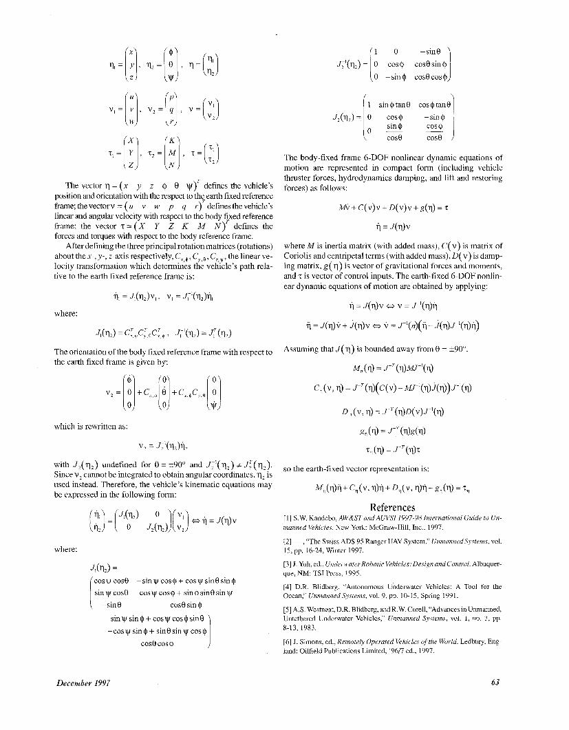
The vector q = (x y z 41 8 v)‘ defines the vehicle’s position and orientation with the respect to th? earth fixed reference frame; thevectorv = (U v w p q r ) defines the vehicle’s linear and angular velocity with respect to the body fixed reference frame; the vector T = ( X Y Z K M N ) T defines the forces and torques with respect to the body reference frame.
After defining the three principal rotation matrices (rotations) about the x-, y-, z-axis respectively, C,,$, C,,,,+,, the linear ve- locity transformation which determines the vehicle’s path rela- tive to the earth fixed reference frame is:
where:
The body-fixed frame 6-DOF nonlinear dynamic equations of motion are represented in compact form (including vehicle thruster forces, hydrodynamics damping, and lift and restoring forces) as follows:
hiEir + C(v)v + D(v)v + g(q) = T
fl = J ( 4 V
where A4 is inertia matrix (with added mass), C( V ) is matrix of Coriolis and centripetal terms (with added mass), D( v) is damp- ing matrix, g( q) is vector of gravitational forces and moments, and z is vector of control inputs. The earth-fixed 6-DOF nonlin- ear dynamic equations of motion are obtained by applying:
T i = J(q)v w v = J-’(q)Tj
fi = J(q)V + &)v a v = J-’(n)(q - i(q)P(q)fl)
The orientation of the body fixed reference frame with respect to the earth fixed frame is given by:
Assuming thatJ(q) is bounded away from = k900.
with J,(q2) imkfined for 8 = *900 and Ji’(%) * Jf(%). Since v, cannot be integrated to obtain angular coordinates, 1s
SO the earth-fixed vector representation is:
M, (IlM + c, ( V > rl)il + D, ( V > +l + g,($ = Tq used instead. Therefore, the vehicle’s kinematic equations may be expressed in the following form:
where:
JSqd = cosw cos0 s iny cos0
-sinyr cos@ + cosy sin0 sin$ cosy cos@ + sin@ sin0siny
-sin0 cos0 sin @
siny sin@+ cosy~cos@sin0 -cosysin@+ sin8sinycos@ 1 cos0 cos @
References [l] S.W. Kandebo, AW&ST and AUVSI 1997-98 International Guide to Un- manned Vehicles. New York: McGraw-Hill, Inc., 1997.
[2] --, “The Swiss ADS 95 Ranger UAV System,” Unmanned Systems, vol. 15, pp. 16-24, Winter 1997.
[3] J. Yuh, ed., UnderwaterRobotic Vehicles: Design andcontrol. Albuquer- que, NM: TSI Press, 1995.
[4] D.R. Blidberg, “Autonomous Underwater Vehicles: A Tool for the Ocean,” Unmanned Systems, vol. 9, pp. 10-15, Spring 1991.
[5] A S . Westneat, D.R. Blidberg, and R.W. Corell, “Advances in Unmanned, Untethered Underwater Vehicles,” Unmanned Systems, vol. 1, no. 3 , pp. 8-13, 1983.
[6] J. Simons, ed., Remotely Operated Vehicles of the World. Ledbury, Eng- land: Oilfield Publications Limited, ‘9617 ed., 1997.
December 1997 63
[7j J. Yuh, “Autonomous Underwater Robot Design,” 1996 World Automa- tion Congress, Tutorial 2: underwater Robotic Systems ASL96-01, Autono- mous Systems Laboratory, Dept. of Mechanical Engineering, University of Hawaii, Honolulu, HI 96822, 1996.
[SI E. Coste-Maniere, H. H. Wang, and A. Peuch, “Control Architectures: What’s Going On?,” in Proceedings of the International Program Develop- ment in Undersea Robotics & Intelligent Control (URIC): A Joint U.S.lPor- tugal Workshop, (Lishoa, Portugal), pp. 54-60, March 2-3, 1995.
[9] K. Ganesan, S.M. Smith, K. White, and T. Flanigan, “A Pragmatic Soft- ware Architecture for UUVs,” in Proceedings of the I996 Symposium on Autonomous Underwater Vehicle Technology, (Monterey, CA), pp. 209-215, June 2-6, 1996.
[lo] D.R. Yoerger, A.M. Bradley, and B. Walden, “System Testing of the Autonomous Benthic Explorer,” in Proceedings of the IARP 2nd Workshop on: Mobile Robots for Subsea Environments, pp. 159-170, May 3-6, 1994.
[ l 11 D.R. Blidberg, S . Chappel, J. Jalbert, R. Turner, G. Sedor, and P. Eaton, “The EAVE AUV Program at the Marine Systems Engineering Laboratory,” in Proceedings oftheIARP 1st Workshop on: MobileRoboisforSubsea Envi- ronments (Monterey, CA), pp. 33-42, Oct. 23-26, 1990.
[ 121 A. Pascoal, C. Silvester, P. Oliveira, D. Fryxell, and V. Silve, “Undersea Robotics Research at IST The AUV MARIUS Programme,” in Proceedings of the International Program Development in Undersea Robotics & Intelli- gent Control (URIC): A Joint U.S.lPortuga1 Workshop, (Lishoa, Portugal), pp. 111-118, March 2-3, 1995.
[ 131 S.M. Rock, H.H. Wang, and M.J. Lee, “Task-DirectedPrecision Control of the MBARIiStanford OTTER AUV,” in Proceedings of the International Program Development in Undersea Robotics & Intelligent Control (URIC): AJoint U.S.iPortuga1 Workshop, (Lisboa,Portugal),pp. 131-138, March2-3, 1995.
[14] S.M. Smith, “An Approach to Intelligent Distributed Control for Autonomous Underwater Vehicles,” in Proceedings of the I994 Symposium on Autonomous Underwater Vehicle Technology, (Cambridge, MA), pp. 105-111, July 19-20, 1994.
11.51 E Janahi-Sharifi and WJ. Wilson, “An Intelligent Assembly Robotics System Based on Relative Pose Measurements,” Journal of Intelligent and Robotic Systems, vol. 12, no. 1, pp. 49-86, 1995.
[ 161 R.A. Brooks, “A Robust Layered Control System for a Mobile Robot,” IEEE Journal of Robotics and Automation, vol. RA-2, pp. 14-23, 1986.
1171 A.J. Boswell and J.R. Leaney, “Using the Subsumption Architecture in an Autonomous Underwater Robot: Expostulations, Extensions and Experi- ences,”in Proceedings of theIARP2ndWorkshop on: Mobile Robots for Sub- sea Environments, pp. 95-106, May 3-6, 1994.
[18] J.G. Bellingham and J.J. Leonard, “Task Configuration with Layered Control,” MIT Sea Grant College Program, Autonomous Underwater Vehi- cles Laboratory Report MITSG 94-245, The MIT Press, Cambridge, MA, 1994.
[ 191 J.G. Bellingham and T.R. Consi, “State Configured Layered Control,” in Proceedings of the IARP 1st Workshop on: Mobile Robots for Subsea Envi- ronments, (Monterey, CA), pp. 75-80, Oct. 23-26, 1990.
[201 A.J. Healey, D.B. Marco, R.B. McGhee, B.P. Brutzinan, R. Cristi, and EA. Papoulias, “Coordinating the Hovering Behaviors of the NPS AUV I1 Using Onboard Sonar Servoing,” in PI-oceedings ofthe IARP 2nd Workshop on: Mobile Robotsfor Subsea Environments, pp. 53-62, May 3-6, 1994.
[21] D. Barnett, S. McClai-an, E. Nelson, M. McDermott, and G. Williams, “Architecture of the Texas A&M Autonomous Underwater Vehicle Coiitrol- ler,” in Proceedings of the I996 Symposium on Autonomous Underwater Ve- hicle Technology, (Monterey, CA), pp. 231-237, June 2-6, 1996.
Kimon P. Valavanis was born in Athens, Greece, in 1957. He received the Diploma in Electrical Engineer- ing, Division of Electronic Engineering (five years of study) from the National Technical University of Ath- ens (NTUA), Athens, Greece, in June 1981. Dr. Valava- nis received the M.Sc. and Ph.D. degrees from Rensselaer Polytechnic Institute (RPI) in electrical en- gineering and computer and systems engineering in 1984 and 1986, respectively. Since January 1991, he
has been with The Center for Advanced Computer Studies, The University of Southwestem Louisiana (USL), where he is currently professor of computer engineering and associate director for research at the USL A-CIM Center Dr Valavanis is a Senior member of IEEE
Denis Gracanin was born in Rijeka, Croatia, in 1963. He received the B.Sc and M.Sc in electrical engineer- ing from the University of Zagreb, Croatia, in 1985 and 1988, respectively He also received the MSc. and Ph D degrees in computer science from the University of Southwestern Louisiana, Lafayette, LA, in 1992 and 1994, respectively. Between 1985 and 1991 he was a lecturer assistant at the Telecommunications Depart- ment, University of Zagreb, Croatia He is currently a
research scientist at the A-CIM Center, University of Southwestem LOLUSI- ana, LA His research interest are in the field of virtual reality, intelligent ro- botic systems, Petri nets, and automated manufacturing systems Dr. Gracanin is a member of IEEE, ACM, AAAI, APS, and SIAM.
Maja Matijasevic received the B S and M.S. degrees in electrical engineering (telecommunications) from the University of Zagreb, Croatia, in 1990 and 1994, re- spectively Since 1991 she has been affiliated with the Telecommunications Department of the Faculty of Electrical Engineering and Computing, Univeisity of Zagreb, Croatia She is currently working toward her Ph D as aresearch associate at the Center for Advanced Computer Studies of the University of Southwestern
Louisiana in Lafayette, LA Her m a n research interests include computer and communications networks, multimedia, and viitual reality
Ramesh Kolluru received his Ph D in computer sci- ence in 1996 from the University of Southwestern Lou- isiana (USL), Lafayette, LA He graduated with honors from USL with a masters’ degree in computer science in 1995, and from Osmania University, India, with a B S in mechanical engineering in 1992 He is currently a re- search scientist at the A-CIM Center, USL. He is closely affiliated with the Robotics and Automation Laboratory of the USL, and is responsible for imple-
mentation of the research agenda at the Center His research interests include the areas of intelligent control, sensor-based control mchitectures, actuators and sensors, modeling and design of complex mechanisms, and factory auto- mation He is a member of the IEEE, RIA, ACM, and a life member of the Phi Kappa Phi Honor Society
Georgios Demetriou received his BSc. degree in elec- trical engineering and his M.Sc. degree in computer en- gineering from the University of Southwestern Louisiana, Lafayette, LA, in the 1991 and 1994, respec- tively. He is currently working toward his Ph.D. in com- puter science at the Center for Advanced Computer Studies of the University of Southwestern Louisiana, Lafayette, LA. His main research interests include ro- botics, control architectures, teleoperations, and com-
puter communications
64 IEEE Control Systems I
-