ashrae 90.1-2004 appendix g guidance notes · ashrae 90.1-2004 appendix g guidance notes ... hvac...
TRANSCRIPT

Princeton University Energy Design Guidelines – ASHRAE 90.1-2004 Guidance Notes
Last saved on 02/05/2011 Page 1 of 16
SD DD 1
DD 2
CD Use the columns to check modeling assumptions at 100% SD, 50% DD, 100% DD, and 85% CD.
- applicable - not applicable
ASHRAE 90.1-2004 Appendix G Guidance Notes
This document provides guidance on the use of ASHRAE 90.1-2004. It is meant
improve consistency in application of 90.1 between different design teams and
energy modelers.
Guidance specific to Princeton University will be denoted with the following symbol:
The guidance provided has been developed to allow energy model results to be
submitted to USGBC for LEED-NC Energy and Atmosphere credits. Guidance
which may conflict with previous USGBC rulings or ASHRAE interpretations will be
noted with a .
It is ultimately the responsibility of the design team to ensure compliance with New
Jersey energy code.
Definitions
Baseline Model/Design: this model reflects the minimum requirements of ASHRAE
90.1-2004.
Proposed Model/Design: this model reflects the building as designed.
HVAC System: refers to airside equipment, not plant equipment.
Thermal Block: a collection of one or more HVAC zones grouped together for
simulation purposes. Spaces need not be continuous to be combined within a
single thermal block.
Zone: a space or group of spaces within a building with heating and cooling
requirements that are sufficiently similar so that desired conditions can be
maintained throughout using a single sensor. The terms room and space are used
interchangeably.
G1. General
G1.1 Performance Rating Method Scope
For the purposes of demonstrating compliance with Princeton University’s
Design Standards, the Appendix G Performance Rating Method shall be used
exclusively. The Energy Cost Budget method (Chapter 11) does not meet this
requirement.
G1.2 Performance Rating
The proposed building must meet all mandatory requirements of ASHRAE 90.1
from sections 5.4, 6.4, 7.4, 8.4, 9.4 and 10.4.
Savings are to be calculated on an annual energy cost basis using the
methodology in the input/output spreadsheet (Appendix 3.3-14).
The annual energy cost for both models must include the impact of all process
loads that use natural gas, electricity, chilled water, hot water, or steam. Process
loads and associated schedules must be kept the same between the Baseline
and Proposed models.

Princeton University Energy Design Guidelines – ASHRAE 90.1-2004 Guidance Notes
Last saved on 02/05/2011 Page 2 of 16
G1.3 Trade-Off Limits
When existing and new construction elements are combined in one project, only
elements being changed are allowed to differ between the Baseline and
Proposed models.
For fit-out (core and shell) spaces, assumptions made for internal loads and
schedules must remain the same between the Baseline and Proposed models.
G1.4 Documentation Requirements
Documentation must be submitted to Princeton University according to the Energy Model
Documentation Schedule. The following supplements are provided:
Utility and Carbon Rate Structure (Appendix 3.3-13)
Input/Output Spreadsheet (Appendix 3.3-14)
Fan Power Calculator (Appendix 3.3-15)
Standard Utilization Schedules (Appendix 3.3-16)
Glazing Factor Calculation Spreadsheet (Appendix 3.3-17)
G2. Simulation General Requirements
G2.1 Performance Calculations
Both models should use the same modeling program, climate file, and utility rate
structure.
G2.2 Simulation Program
All simulation programs permitted by ASHRAE 90.1-2004 are permitted for
demonstrating compliance with Princeton University energy performance targets.
These include, but are not limited to:
o Trane Trace 700 or Carrier HAP
o DOE-2 based programs (eQuest, VisualDOE, PowerDOE)
o EnergyPlus
o Energy-10 (buildings less than 20,000 sf only)
G2.3 Climatic Data
Both models should use the Trenton-Mercer County TMY3 climate data file
available for download from:
http://apps1.eere.energy.gov/buildings/energyplus/cfm/weather_data.cfm
G2.4 Energy Rates
Both models should use the utility rate and carbon rate structures provided in
Appendix 3.3-13.
G2.5 Exceptional Calculation Methods
Proposed Only
Systems that cannot be directly modeled in the simulation program being used
should be documented as exceptional calculation methods and highlighted in the
Input/Output spreadsheet.
These systems include, but are not limited to:
o Natural or Mixed Mode Ventilation

Princeton University Energy Design Guidelines – ASHRAE 90.1-2004 Guidance Notes
Last saved on 02/05/2011 Page 3 of 16
o Underfloor Air Distribution
o Displacement Ventilation
o Active or Passive Chilled Beams
o Radiant Panel or Floor Cooling and Heating
G3. Calculation of the Proposed and Baseline Building Performance
G3.1 Building Performance Calculations
G3.1.1 Baseline HVAC System Type and Description
Baseline Only
The Baseline system type should be selected according to section G3.1.1 in this
document.
The Baseline model should have the same number of systems and the same
zone assignments to systems as the Proposed model to allow for direct
comparison between models.
G3.1.1.1 Purchased Heat
When the Proposed design makes use of the Princeton University steam system,
purchased steam should be modeled in both the Baseline and Proposed models
using the standard utility rate structure.
Table G3.1 Modeling Requirements for Calculating Proposed and Baseline Building Performance
1. Design Model
Baseline Only
The Baseline model must have the same basic geometry, thermal blocks,
zoning, process loads, and schedules as the Proposed model. The conditioned
floor should be identical between the Baseline and Proposed models.
Proposed Only
The Proposed model is meant to approximate, as closely as possible, the
proposed design of the project.
Even if no heating and/or cooling system is designed for a zone, the zone must
be included in the energy model to properly account for the energy consumption
of zone lighting and/or equipment.
Only elements of the project that are included in the current project scope are
allowed to differ between the Baseline and Proposed models. For example, any
future lab fit-out space must be assumed to be the same between both models
with respect to lighting, internal loads, airside systems, etc.
2. Additions and Alterations
Baseline and Proposed
The boundaries of the energy study should be agreed upon with the Princeton
University Project Manager at the beginning of Schematic Design.
3. Space Use Classification
Baseline and Proposed
Space classifications for each zone should be documented in the Input/Output
Princeton University Energy Design Guidelines – ASHRAE 90.1-2004 Guidance Notes
Last saved on 02/05/2011 Page 4 of 16
spreadsheet.
4. Schedules
Baseline and Proposed
Separate schedules should be used for occupancy, ventilation, lighting and
equipment.
Schedules should be the same for both models, except as noted in this
document. Use schedules provided as Appendix 3.13-16.
5. Building Envelope
Baseline Only
The Baseline model should be run in four orientations (0 degree rotation, 90
degree rotation, 180 degree rotation, and 270 degree rotation). If the averaged
result is greater than the result for as designed building orientation (0 degrees),
there is room for improvement to the building’s massing and fenestration
placement.
Baseline model envelope thermal properties should be based on 90.1, Chapter
5, Climate Zone 5A.
No external or internal shading devices should be included in the Baseline
model.
The Baseline model building envelope component areas should be identical to
the Proposed model with the following exceptions:
o The maximum allowed above-grade fenestration to wall ratio in the
Baseline model is 40%.
o The maximum skylight to roof ratio in the Baseline model is 5%. Skylight
is defined as fenestration with a slope of 60 degrees or less from
horizontal.
o Fenestration should be proportionally scaled in the Baseline model to
meet the above ratio limits. This applies only if the ratios are exceeded in
the Proposed model.
Proposed Only
As designed building envelope areas should be modeled.
Permanent external shading devices should be included in the Proposed model.
Internal shading that is not automated may not be included.
Fenestration
o All U-values should be assembly U-values. These values include the
effect of framing, edge spacers, and local thermal bridging. Use of
center-of-glass properties is not acceptable.
o All SHGC values should be assembly SHGC values. These values
include the effect of framing, edge spacers, and local thermal bridging.
Use of center-of-glass properties is not acceptable.
Envelope thermal performance values in 90.1, Normative Appendix A should be
used, in the absence of actual thermal calculations.
Green roofs and high reflectance roofs (EnergyStar) may be modeled with a
reflectance of 0.45.

Princeton University Energy Design Guidelines – ASHRAE 90.1-2004 Guidance Notes
Last saved on 02/05/2011 Page 5 of 16
Further guidance is provided in the Energy Guidelines Section 8: Envelope
Design Guidelines.
6. Lighting
Baseline Only
Lighting power densities may be specified either by the use of the space-by-
space method (90.1, Table 9.6.1) or the building area method (90.1, Table 9.5.1).
The two methods should not be combined in the same model. Lighting power
allowances should be tracked using the Input/Output spreadsheet.
Daylight control should be not be modeled in the Baseline model.
External lighting should be included, as per the limits described in 90.1, Table
9.4.5.
Proposed Only
Use estimated or as-designed lighting power densities.
Daylight control should be calculated by the energy modeling software when
possible. The use of ray-tracing daylight calculation software to create a lighting
use schedule is preferable.
For automatic lighting systems in addition to those required for minimum code
compliance, power adjustments should be made using Table G3.2. Alternatively,
lighting schedule adjustments can be made to the proposed model with credible
technical documentation.
External lighting should be included, as designed.
7. Thermal Blocks – HVAC Zones Designed
Baseline and Proposed
Thermal blocks should be modeled as designed.
Floor areas used in the simulation tool should be measured from the inner face
of interior walls and outer face of perimeter walls. Areas must remain the same
between the Baseline and Proposed models.
8. Thermal Blocks – HVAC Zones Not Designed
Baseline and Proposed
Separate thermal blocks should be assumed for internal and perimeter spaces.
Spaces with exposed roof, below-grade wall, or slab-on-grade conditions should
be modeled separately from other spaces without one of these conditions.
9. Thermal Blocks – Multifamily Residential Buildings
Baseline and Proposed
Residence halls should be modeled using one zone for all adjacent units having
the similar perimeter exposure. Units with multiple perimeter exposures should
be modeled separately.
10. HVAC Systems
Baseline Only
The Baseline HVAC system should be modeled following the guidance in Table
G3.1.1A and G3.1.1B.

Princeton University Energy Design Guidelines – ASHRAE 90.1-2004 Guidance Notes
Last saved on 02/05/2011 Page 6 of 16
Proposed Only
The Proposed systems should be modeled as designed.
11. Service Hot Water Systems
Baseline Only
The Baseline model should use the same service hot water demand and fuel
source as the Proposed model. Efficiencies should be as per 90.1, Chapter 7.
Proposed Only
If a service hot water system has not yet been designed, a system should be
included with an estimated capacity based on tables in the 90.1 User’s Manual.
The fuel source should be purchased steam.
If a service hot water system has been designed, actual capacities should be
used in both models.
Credit may be taken for hot water use reductions in this calculation provided
that the reduction is demonstrated using the Input/Output spreadsheet.
12. Receptacle and Other Loads
Baseline and Proposed
Receptacle loads should include all process energy uses within the project
including, but not limited to:
o Elevators and escalators
o Laboratory equipment
o Computers and other office equipment
o Appliances
o Vending machines
Receptacle loads should be determined based on guidance in the ASHRAE
Fundamentals Handbook, measured data, or calculated equipment loads.
Receptacle loads must be kept the same between the Proposed and Baseline
models.
o Exception: credit may be taken for use of equipment that is more
efficient than industry norms. Any credit taken must receive prior
approval from PU and be stated in the Input/Output spreadsheet.
13. Modeling Limitations to the Simulation Program
Current energy simulation tools have inherent modeling limitations. Where
limitations occur, include a description in the Input/Output spreadsheet.
G3.1.2 General Baseline HVAC System Requirements
Table G3.1.1A Baseline HVAC System Types
Baseline Only
This table gives guidance on the baseline HVAC system type based on building type, size, fuel source, and number of floors.
When determining the number of floors, include below-grade levels in the count. Do not include non-occupied mechanical levels in the count.

Princeton University Energy Design Guidelines – ASHRAE 90.1-2004 Guidance Notes
Last saved on 02/05/2011 Page 7 of 16
When there is no heating system, use the “electric and other” column.
When there is a mix of non-residential and residential spaces within a building, use the majority (>50%) space type, measured by gross square footage.
Labs: for an individual air-handling unit system serving spaces with a minimum of 5,000 cfm exhaust, use System Type 5 or System Type 7. Reduce the exhaust and makeup air volume to 50% of peak design during unoccupied
periods ( 5% occupancy). This applies to airflow driven (e.g. fume-hood) labs ONLY.
All-electric buildings: heating to be electric resistance.
Geothermal heat pump systems: assume baseline systems 1, 3, 5, or 7.
Table G3.1.1B Baseline System Descriptions
Baseline Only
This table describes the baseline system types.
The type is determined from Table G3.1.1A.
For the majority of projects at Princeton University, system types using “fossil
fuel, fossil/electric hybrid, and purchased heat” will apply.
G3.1.2.1 Equipment Efficiencies
Baseline Only
HVAC equipment should be modeled as having the minimum efficiency levels
described in Section 6.4.
Note that EER and COP ratings sometimes include fan energy.
Use the following correlation chart to determine which 90.1, Chapter 6 efficiency
ratings to use:
System Type Efficiency Guidance
1. Packaged terminal air
conditioner
(Will not apply to most PU
buildings)
Use “PTAC (cooling mode) new construction” efficiency formula in
Table 6.8.1D for cooling.
Use peak system cooling load (Btu/h) to determine
efficiency level.
Use “Boilers, hot water” efficiency values in Table 6.8.1F for
heating.
Use peak building heating load (Btu/h) to determine
efficiency level.
Note that this will not apply for buildings that use PU
campus steam.
2. Packaged terminal heat
pump
(Will not apply to most PU
buildings)
Use “PTHP (cooling mode) new construction” efficiency formula in
Table 6.8.1D for cooling.
Use “PTHP (heating mode) new construction” efficiency formula in
Table 6.8.1D for heating.
Use peak system cooling load (Btu/h) to determine
efficiency level.
Princeton University Energy Design Guidelines – ASHRAE 90.1-2004 Guidance Notes
Last saved on 02/05/2011 Page 8 of 16
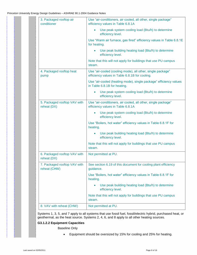
3. Packaged rooftop air
conditioner
Use “air-conditioners, air cooled, all other, single package”
efficiency values in Table 6.8.1A
Use peak system cooling load (Btu/h) to determine
efficiency level.
Use “Warm air furnace, gas fired” efficiency values in Table 6.8.1E
for heating.
Use peak building heating load (Btu/h) to determine
efficiency level.
Note that this will not apply for buildings that use PU campus
steam.
4. Packaged rooftop heat
pump
Use “air-cooled (cooling mode), all other, single package”
efficiency values in Table 6.8.1B for cooling.
Use “air-cooled (heating mode), single package” efficiency values
in Table 6.8.1B for heating.
Use peak system cooling load (Btu/h) to determine
efficiency level.
5. Packaged rooftop VAV with
reheat (DX)
Use “air-conditioners, air cooled, all other, single package”
efficiency values in Table 6.8.1A
Use peak system cooling load (Btu/h) to determine
efficiency level.
Use “Boilers, hot water” efficiency values in Table 6.8.1F for
heating.
Use peak building heating load (Btu/h) to determine
efficiency level.
Note that this will not apply for buildings that use PU campus
steam.
6. Packaged rooftop VAV with
reheat (DX)
Not permitted at PU.
7. Packaged rooftop VAV with
reheat (CHW)
See section 6.19 of this document for cooling plant efficiency
guidance.
Use “Boilers, hot water” efficiency values in Table 6.8.1F for
heating.
Use peak building heating load (Btu/h) to determine
efficiency level.
Note that this will not apply for buildings that use PU campus
steam.
8. VAV with reheat (CHW) Not permitted at PU.
Systems 1, 3, 5, and 7 apply to all systems that use fossil fuel, fossil/electric hybrid, purchased heat, or geothermal, as the heat source. Systems 2, 4, 6, and 8 apply to all other heating sources.
G3.1.2.2 Equipment Capacities
Baseline Only
Equipment should be oversized by 15% for cooling and 25% for heating.

Princeton University Energy Design Guidelines – ASHRAE 90.1-2004 Guidance Notes
Last saved on 02/05/2011 Page 9 of 16
Sizing should follow the same process taken when determining peak cooling and
heating loads with additional guidance from 6.3 of this document.
Capacity adjustments should be made at plant and coil level.
Baseline and Proposed
Unmet load hours for both cases must be less than 300 hours (out of 8,760).
Note that most simulation tools report separate heating load hours not met from
cooling load hours not met. The sum of these two apply to these requirements.
Unmet load hours cannot differ between cases by more than 50 hours.
Unmet load hours are problematic in energy simulation tools, given the use of a
one-hour simulation time step coupled with spaces with large warm-up loads
and/or low airflow rates. Do not adjust schedules as a primary solution. Rather,
take the following steps:
Both models < 300 unmet load hours and proposed exceeds baseline by
> 50 unmet load hours: decrease baseline system capacities
incrementally.
Both models < 300 unmet load hours and baseline exceeds proposed by
> 50 unmet load hours: increase baseline system capacities
incrementally.
Either model > 300 unmet load hours: increase baseline and/or proposed
system capacities incrementally. Note that having a significant number of
load hours not met can be an indication of an inadequate HVAC system
design.
Capacity adjustments to resolve unmet load hours issues should be
made at coil level.
G3.1.2.2.1 Sizing Runs
Baseline Only
Baseline model sizing runs (peak cooling and heating load determination)
should be developed using 99.6% ASHRAE heating design temperatures and
1% ASHRAE dry-bulb and 1% wet-bulb cooling design temperatures. This
applies to energy modeling only. PU design standard conditions should be used
for actual equipment sizing. Reference: ASHRAE Fundamentals.
G3.1.2.3 Preheat Coils
Baseline Only
If there is a pre-heat coil in the proposed design system, a pre-heat coil should
be modeled in the baseline design system also.
G3.2.1.4 Fan System Operation
Baseline and Proposed
Fans should be modeled in both cases to operate continuously anytime
occupancy is greater than 5% of design. Fans should cycle to meet heating and
cooling loads during unoccupied hours.
Exception: for spaces with health and safety minimum airflow requirements
(labs or medical facility), fans should operate continuously.
G3.2.1.5 Ventilation
Baseline and Proposed

Princeton University Energy Design Guidelines – ASHRAE 90.1-2004 Guidance Notes
Last saved on 02/05/2011 Page 10 of 16
Ventilation rates should remain the same in both cases. This applies even if
ventilation rates provided are higher than minimums prescribed by NJ
Mechanical Code and/or ASHRAE 62.1. Fume hood ventilation in the baseline
and proposed models shall use the standard utilization schedules.
Exception 1: when demand controlled ventilation is used, the proposed model
ventilation rates may be adjusted through use of the appropriate occupancy
schedule contained in Appendix 3.3-16.
Exception 2: proposed model ventilation rates may be adjusted to account for
use of fume hood auto-sash closure mechanisms by using the
“Weekend/Holiday” schedule at all times.
The use of low-flow fume hoods is encouraged. As a process credit, the
baseline model should assume a face velocity of 100 fpm. The proposed model
should include actual fume hood face velocity.
Ventilation schedules may not deviate from those in Appendix 3.3-16 without
prior approval from Princeton University.
G3.2.1.6 Economizers
G3.2.1.7 Economizer High-Limit Shutoff
Baseline Only
Princeton University is at the eastern edge of Mercer County, which falls under
ASHRAE 90.1 Climate Zone 5A.
Outdoor air economizers should be provided as per the following:
System Type Economizer Requirement
1. Packaged terminal air conditioner
2. Packaged terminal heat pump
Not required
3. Packaged rooftop air conditioner
4. Packaged rooftop heat pump
5. Packaged rooftop VAV with reheat (DX)
6. Packaged rooftop VAV with reheat (DX)
7. Packaged rooftop VAV with reheat (CHW)
8. VAV with reheat (CHW)
Economizer Included - 70F High-Limit Shutoff
Exception: systems that make use of gas-phase filtration to meet requirements
of ASHRAE 62.1 (Section 6.1.2).
Proposed Only
Model airside economizers as designed. Ensure that the control algorithm
matches what is specified (e.g. enthalpy, dry-bulb, fixed differential, etc.).
G3.1.2.8 Design Airflow Rates
Baseline Only
System baseline design supply airflow rates should be based on a supply-air to
room-air temperature difference of 20F. For example, if the target space
temperature is 77F, the design supply temperature should be set at 57F. This
requirement ties directly into calculation of baseline system fan power.
Princeton University Energy Design Guidelines – ASHRAE 90.1-2004 Guidance Notes
Last saved on 02/05/2011 Page 11 of 16
If there are return fans in the proposed design, return fans should also be
modeled in the baseline model with a design airflow rate equal to 90% of the
supply.
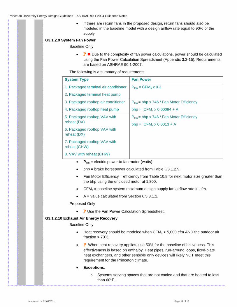
G3.1.2.9 System Fan Power
Baseline Only
Due to the complexity of fan power calculations, power should be calculated
using the Fan Power Calculation Spreadsheet (Appendix 3.3-15). Requirements
are based on ASHRAE 90.1-2007.
The following is a summary of requirements:
System Type Fan Power
1. Packaged terminal air conditioner
2. Packaged terminal heat pump
Pfan = CFMs x 0.3
3. Packaged rooftop air conditioner
4. Packaged rooftop heat pump
Pfan = bhp x 746 / Fan Motor Efficiency
bhp = CFMs x 0.00094 + A
5. Packaged rooftop VAV with
reheat (DX)
6. Packaged rooftop VAV with
reheat (DX)
7. Packaged rooftop VAV with
reheat (CHW)
8. VAV with reheat (CHW)
Pfan = bhp x 746 / Fan Motor Efficiency
bhp = CFMs x 0.0013 + A
Pfan = electric power to fan motor (watts).
bhp = brake horsepower calculated from Table G3.1.2.9.
Fan Motor Efficiency = efficiency from Table 10.8 for next motor size greater than
the bhp using the enclosed motor at 1,800.
CFMs = baseline system maximum design supply fan airflow rate in cfm.
A = value calculated from Section 6.5.3.1.1.
Proposed Only
Use the Fan Power Calculation Spreadsheet.
G3.1.2.10 Exhaust Air Energy Recovery
Baseline Only
Heat recovery should be modeled when CFMs > 5,000 cfm AND the outdoor air
fraction > 70%.
When heat recovery applies, use 50% for the baseline effectiveness. This
effectiveness is based on enthalpy. Heat pipes, run-around loops, fixed-plate
heat exchangers, and other sensible only devices will likely NOT meet this
requirement for the Princeton climate.
Exceptions:
o Systems serving spaces that are not cooled and that are heated to less
than 60F.

Princeton University Energy Design Guidelines – ASHRAE 90.1-2004 Guidance Notes
Last saved on 02/05/2011 Page 12 of 16
o Systems exhausting toxic, flammable, or corrosive fumes or paint or
dust. This exception only applies if heat recovery is not used in the
proposed design. Labs are addressed separately from this exception.
o Commercial kitchen hoods classified as Type I by NFPA 96. This
exception only applies if heat recovery is not used in the proposed
design.
o When the exhaust rate that would return to the heat recovery device is
less than 75% of the design outdoor flow. This exception only applies if
heat recovery is not used in the proposed design.
o For lab systems with exhaust rates of 5,000 cfm or less. For lab systems
with exhaust rates less than 5,000 cfm, heat recovery does not need to
be modeled in the baseline, even if it is used.
Proposed Only
Model heat recovery as designed. Ensure that sensible and latent heat recovery
effectiveness are matched to actual equipment sections. Ensure that control
algorithms and airside pressure is properly modeled. Bypass of the heat recovery
device is required to allow air economizer operation, when included.
G3.1.3 System-Specific Baseline HVAC System Requirements
The following items apply to only certain baseline types.
G3.1.3.1 Heat Pumps (Systems 2 and 4)
Baseline Only
Model with auxiliary electric heat. Energize only when outdoor air temperature is
< 40F.
G3.1.3.2 Type and Number of Boilers (Systems 1, 5, and 7)
Baseline Only
For the Appendix G compliant model (Baseline 1 of the PU Energy
Guidelines), and buildings that use Princeton University steam, this section does
not apply. For Baseline 3 required by the PU Energy Guidelines, this section
shall apply.
For buildings with stand-alone heating, the baseline boiler should use the same
fuel source as the proposed design. This will typically be natural gas.
Model a single boiler if the heating plant serves 15,000 gsf.
Model two equally sized boilers if the heating plant serves > 15,000 gsf.
G3.1.3.3 Hot-Water Supply Temperature (Systems 1, 5, and 7)
Baseline Only
Model the hot-water design supply water temperature at 180F. The return water
temperature should be modeled as 130F. Pumps should be sized accordingly.
G3.1.3.4 Hot-Water Supply Temperature Reset (Systems 1, 5, and 7)
Baseline Only
Hot water supply temperatures should be reset as follows:
Outdoor Temperature Hot Water Supply Temperature

Princeton University Energy Design Guidelines – ASHRAE 90.1-2004 Guidance Notes
Last saved on 02/05/2011 Page 13 of 16
20F 180F
Between 20F and 50F Vary linearly between 150F and 180F
50F 150F
G3.1.3.5 Hot-Water Pumps (Systems 1, 5, and 7)
Baseline Only
Baseline power should be modeled at 19 W/gpm. The flow rate used should be
calculated at the baseline peak hot water demand with a 50F delta. For
example, if 500 gpm is the peak flow rate, the baseline pump power is 9,500 W
(12.73 HP).
Model hot water pump system as primary only.
Model pump control using variable-speed drives for system serving < 120,000 sf.
Model pump control by riding the pump curve (constant-volume) for system
serving 120,000 sf.
Proposed Only
Model pump system as designed. Do not use nameplate horsepower in the
model. Use actual operating horsepower.
G3.1.3.6 Piping Losses (Systems 1, 5, 7, and 8)
Baseline and Proposed
Do not model piping heat gains or losses for any system.
G3.1.3.7 Type and Number of Chillers (Systems 7 and 8)
Baseline Only
Although most buildings at Princeton University make use of the campus
chilled water system, electric chillers must be modeled in the baseline. The
impact of the campus plant is addressed through use of the utility rate structure
described in Appendix 3.3-13.
The baseline chillers should be modeled based on the peak building cooling load
:
Building Peak
Cooling Load
Number and Type of Chillers COP / IPLV
< 150 tons 1 water-cooled screw chiller 4.45 / 5.2 (From Table 6.8.1C)
150 tons,
300 tons
1 water-cooled screw chiller 4.90 / 5.6 (From Table 6.8.1C)
> 300 tons,
< 600 tons
2 water-cooled screw chillers
sized equally
4.90 / 5.6 (From Table 6.8.1C)
600 tons 2 water-cooled centrifugal chillers
minimum with chillers added that
no chiller is larger than 800 tons,
all sized equally.
6.1 / 6.4 (From Table 6.8.1J)
The above chart is from ASHRAE 90.1-2007 and represents a substantial change
from 90.1-2004, but one that is more appropriate. The equivalent chart in 90.1-2004

Princeton University Energy Design Guidelines – ASHRAE 90.1-2004 Guidance Notes
Last saved on 02/05/2011 Page 14 of 16
based the baseline chiller selection on building square footage.
G3.1.3.8 Chilled Water Design Supply Temperature (Systems 7 and 8)
Baseline Only
The baseline chilled water design supply temperature should be modeled at 44F
and return water temperature at 56F.
Proposed Only
The actual chilled water design conditions should be used. Princeton
University default values are 45F with a 20F delta. No actual electric chiller(s)
should be modeled. Performance is addressed through use of the chilled water
utility rate structure described in Appendix 3.3-13.
G3.1.3.9 Chilled Water Supply Temperature Reset (Systems 7 and 8)
Baseline Only
Chilled water supply temperatures should be reset as follows:
Outdoor Temperature Chilled Water Supply Temperature
80F 44F
Between 60F and 80F Vary linearly between 44F and 54F
60F 54F
G3.1.3.10 Chilled Water Pumps (Systems 7 and 8)
Baseline Only
Baseline power should be modeled at 22 W/gpm. The flow rate used should be
calculated at the baseline peak chilled water demand with a 12F delta. For
example, if 500 gpm is the peak flow rate, the baseline pump power is 11,000 W
(14.75 HP).
Model primary/secondary chilled water pumping scheme with variable-speed
drive on the secondary pump for peak building cooling load ≥ 300 tons.
Model primary/secondary chilled water pumping scheme with secondary pump
riding the pump curve (constant volume) for peak building cooling load < 300
tons.
Proposed Only
Model pump system as designed. Do not use nameplate horsepower in the
model. Use actual operating horsepower.
G3.1.3.11 Heat Rejection (Systems 7 and 8)
Baseline Only
Although most buildings at Princeton University make use of the campus
chilled water system, heat rejection must be modeled in the baseline. The
impact of the campus plant is addressed through use of the utility rate structure
described in Appendix 3.3-13.
The heat rejection device should be an axial fan cooling tower with two-speed
fans with fan power totaling 38.2 gpm/hp (Table 6.8.1G). The gpm should be
calculated based on a condenser water delta of 10F with leaving condenser
water temperature of 85F at design wet bulb conditions. For example, if the
condenser water flow rate is 500 gpm, the baseline fan power would be 13.09
Princeton University Energy Design Guidelines – ASHRAE 90.1-2004 Guidance Notes
Last saved on 02/05/2011 Page 15 of 16
HP.
The leaving condenser water temperature should be allowed to float between
70F and 85F, weather permitting.
Baseline condenser water pump power should be modeled at 19 W/gpm. The
flow rate used should be calculated at the baseline peak condenser water
demand with a 10F delta. For example, if 500 gpm is the peak flow rate, the
baseline pump power is 9,500 W (12.73 HP).
G3.1.3.12 Supply Air Temperature Reset (Systems 5 through 8)
Baseline Only
The air temperature for cooling should be reset upwards by 5F under minimum
cooling load conditions.
G3.1.3.13 VAV Minimum Flow Setpoints (Systems 5 and 7)
Baseline Only
Minimum volume setpoints for VAV reheat boxes should be 0.4 cfm/sf or the
minimum ventilation rate, whichever is larger.
For labs, the minimum VAV box setpoint should be set to what is required for
health and safety.
G3.1.3.14 Fan Power (Systems 6 and 8)
Not applicable to Princeton University buildings.
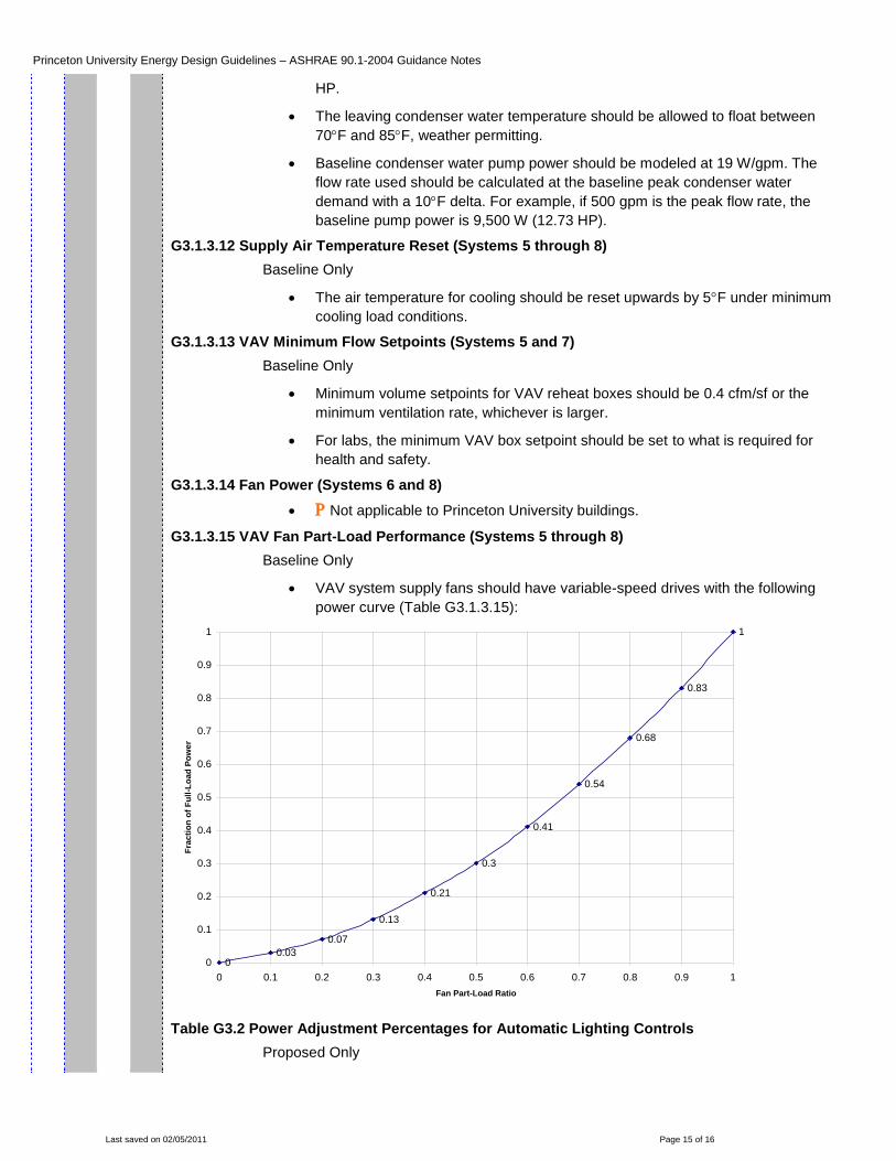
G3.1.3.15 VAV Fan Part-Load Performance (Systems 5 through 8)
Baseline Only
VAV system supply fans should have variable-speed drives with the following
power curve (Table G3.1.3.15):
00.03
0.07
0.13
0.21
0.3
0.41
0.54
0.68
0.83
1
0
0.1
0.2
0.3
0.4
0.5
0.6
0.7
0.8
0.9
1
0 0.1 0.2 0.3 0.4 0.5 0.6 0.7 0.8 0.9 1
Fan Part-Load Ratio
Fra
cti
on
of
Fu
ll-L
oad
Po
wer
Table G3.2 Power Adjustment Percentages for Automatic Lighting Controls
Proposed Only

Princeton University Energy Design Guidelines – ASHRAE 90.1-2004 Guidance Notes
Last saved on 02/05/2011 Page 16 of 16
The following power adjustments should be made to account for automatic
lighting controls:
Automatic Control
Device
Non-24-h and 5,000 sf total
conditioned building area
All Other
1. Programmable
timing control
10% 0%
2. Occupancy
sensor
15% 10%
3. Occupancy
sensor and
programmable
timing control
15% 10%