appendix e. design samples and drawings - new jersey · appendix e. design samples and drawings e-...
TRANSCRIPT

Appendix E Page E-1
Appendix E. Design Samples and Drawings
E- 1 Sample Technology Outlet Configurations
It is recommended that schools define standard technology outlet configurations for different uses and users. Designations can be modified from school to school with the exact components of each outlet adapted to local conditions. The following chart depicts the typical types of outlets defined, where it is used, the types of jacks in the outlets, and a sample graphic of the outlet. These outlet types will be referenced in the sample diagrams that follow.
Outlet Work areas Jacks Graphic
T Teacher 2 - data 1 - desk phone 1 - video
TV Multimedia 1 - RF connector 1 - S-video 1 - video in 1 - right audio in 1 - left audio in 1 - VGA 1 - DVI-D 1 - USB
As Required by
Design
2S Student 2 - data 2 - video
4S Student 4 - data
A Administrator 2 - data 1 - desk phone 1 - video
V Video 1 - RF video

Appendix E Page E-2
Outlet Work areas Jacks Graphic
P Utility 1 - wall phone
WAP All 1 - data
Note: 1. Data, phone and unassigned jacks are RJ-45. Video jacks are BNC or Cat 6
type. 2. Data jacks have blue bezel, phone jacks have orange bezel, and unassigned
jacks have red bezels. Video jacks have red bezels. 3. Outlets mounted at receptacle height (18” above finished floor – AFF) except
for: P which is mounted at 44" AFF V outlets that are mounted at approx. 7' WAP outlets that are mounted approx. 12” below hung ceiling
These outlet configurations become the basic building blocks for providing network services throughout the facility. These outlet configurations will enable voice, video, and data transfer from the desktop for students, teachers, school administrators, and staff as required.
Note on Outlet Recommendation samples: in new construction, backboxes and conduits will be behind walls. In renovations or technology upgrade projects where mounting behind the walls is not practical, surface mounted raceway may be used.
Appendix E Page E-3
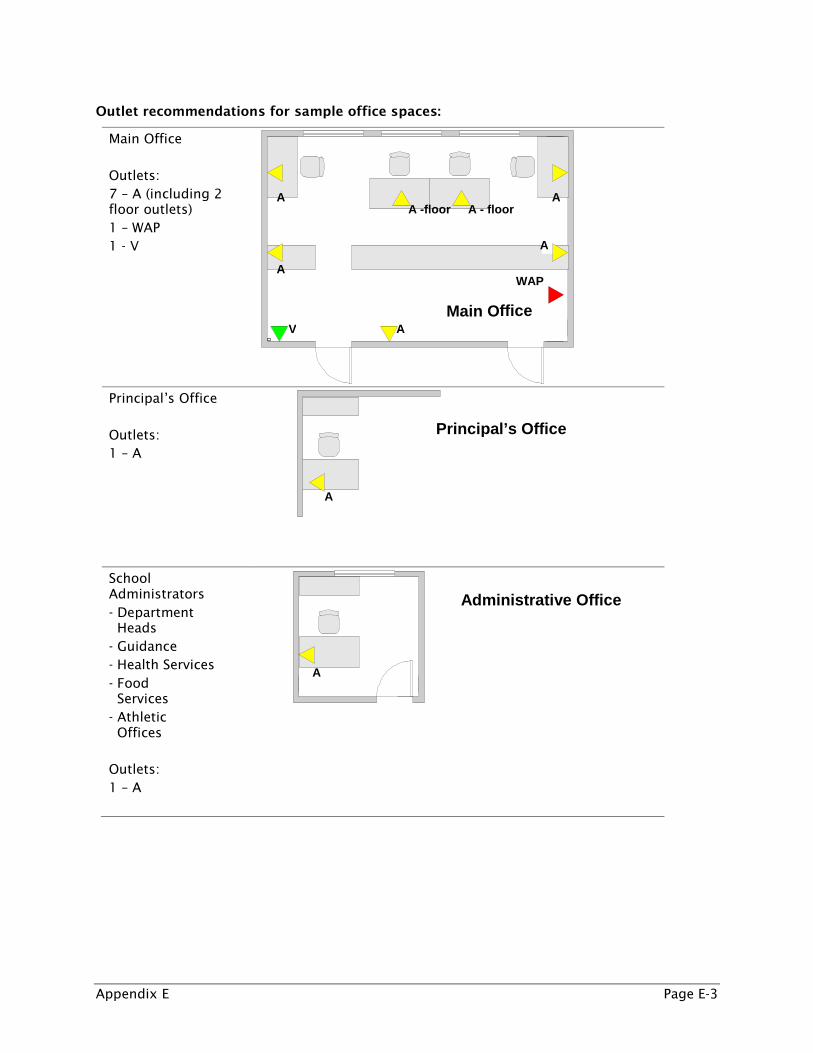
Outlet recommendations for sample office spaces:
Main Office Outlets: 7 – A (including 2 floor outlets) 1 – WAP 1 - V
Principal’s Office Outlets: 1 – A
School Administrators - Department Heads - Guidance - Health Services - Food Services - Athletic Offices Outlets: 1 – A
A
A
Main O ffice
A
A -floor A - floor A
A
A V
WAP
A
Administrative Office
Principal’s Office

Appendix E Page E-4
Sample outlet recommendations for classroom spaces:
Standard Instructional Classroom Outlets: 1 – T 1 – 4S 1 – 2S Consider outlet in ceiling for mounted projector connection to the network
In addition to the standard classroom space, some content areas such as science labs and world languages classrooms will require unique configurations. A variety of science laboratory layouts are available for middle and high school facilities depending on available space and existing room constraints. Outlets should be positioned in a manner so that students can safely use technology tools and resources such as digital microscopes, probes, and sensors within the laboratory environment.
Sample outlet recommendations for science laboratory:
Science Classroom Outlets: 1 – T 4 – 4S 1 - WAP
T
2S
4S
Outlet: T
4S
4S
4S
4S
WAP
Classroom
Science Lab

Appendix E Page E-5
Sample outlet recommendations for rectangular back- to- back stations computer lab configuration:
Computer Lab Outlets: 1 – T 8 – 4S Consider outlet in ceiling for mounted projector connection to the network 1 - WAP
Sample outlet recommendations for Teacher’s work room:
Teacher Workroom Outlets: 1 - A 1 – P 1 - WAP
4S
4S
4S
4S
T
Computer Lab
4S 4S
4S 4S
WAP
A
P WAP
Workroom

Appendix E Page E-6
Sample outlet recommendations for a typical Library Media Center office and check out area:
Media Center Outlets: 2 – A 3 – 4S 1 – T 1- WAP
Sample outlet recommendations for a typical auditorium/theater:
Theater Outlets: 4 – T 2 – P 1 - WAP
Media Center Office
4S
Checkout
A
A
T
4S
4S
WAP
P
Stage
T
P
T
Control Room T T
WAP

Appendix E Page E-7
Sample outlet recommendations for typical food services office and cafeteria area:
Cafeteria Outlets: 2 – V 3 – A 1 – P 1 - WAP
.
V
Cafeteria
A
Lunch line
P
Food Service Office
A
A
Kitchen V
WAP

Appendix E Page E-8
E-2 Instructional Space Furniture and Space Layout Samples
*The flexible space sample above features movable student furniture and wireless access points making it an appropriate layout for one-to-one computing environments.

Appendix E Page E-9
Appendix E Page E-10
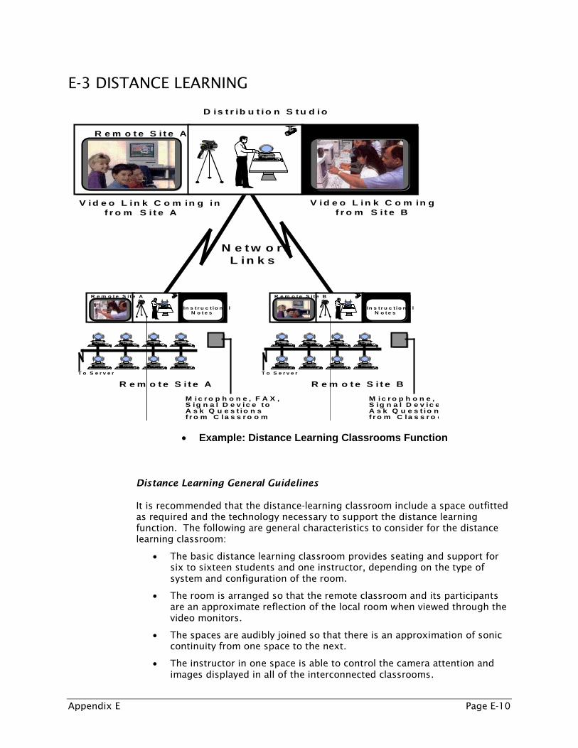
E-3 DISTANCE LEARNING
D is t r ib u t io n S tu d io
N e t w o r kL in k s
R e m o t e S i te A
S i t eB
V id e oIn s t r u c t io n a l
N o t e s
T o S e r v e r
R e m o t e S i t e A
M i c r o p h o n e , F A X , S ig n a l D e v ic e t oA s k Q u e s t io n sf r o m C la s s r o o m
M i c r o p h o n e , S ig n a l D e v ic e A s k Q u e s t io nf r o m C la s s r o o
R e m o t e S i t e A R e m o t e S i t e B
V id e o L in k C o m in g f r o m S i t e B
V id e o L in k C o m in g in f r o m S i t e A
R e m o t e S i te B
S i t eA
V id e oIn s t r u c t io n a l
N o t e s
T o S e r v e r
R e m o t e S i t e B
• Example: Distance Learning Classrooms Function
Distance Learning General Guidelines
It is recommended that the distance-learning classroom include a space outfitted as required and the technology necessary to support the distance learning function. The following are general characteristics to consider for the distance learning classroom:
• The basic distance learning classroom provides seating and support for six to sixteen students and one instructor, depending on the type of system and configuration of the room.
• The room is arranged so that the remote classroom and its participants are an approximate reflection of the local room when viewed through the video monitors.
• The spaces are audibly joined so that there is an approximation of sonic continuity from one space to the next.
• The instructor in one space is able to control the camera attention and images displayed in all of the interconnected classrooms.

Appendix E Page E-11
Distance learning spaces generally operate in four main modes:
1. As a local or remote site in a virtual classroom within the District.
2. As a local or a remote site connecting to a similar space outside the District for learning, or video conferencing.
3. As a media or program presentation space for a small group.
4. As a presentation space to present a broadcast feed from a local feed or a source via the Internet.
The instructor’s station includes:
• document camera with light
• computer with the display interconnected to the presentation and conferencing systems that can be used for scheduling, control or presentation
• VHS/DVD and CD players
• System control panel
The room can serve as a presentation space or normal classroom when not needed to support distance learning.
Sample Design Types
Examples of systems are of three types suited to one of three applications:
• Type 1: Small classroom, frequently in the area of the library/media center, where a transportable unit is brought in as needed to satisfy a temporary need. These classrooms can be implemented in any school or office facility and require connection only to power and communication lines. Additionally, computers with audio and video components can establish one-to-one distance learning environments provided that video to the desktop capacity exists.
• Type 2: Elementary and middle school classroom with dedicated distance-learning capabilities. These rooms are outfitted with permanent installation of the distance learning system elements as needed. These spaces are intended primarily for receipt of educational broadcasts, full-class interaction, and presentations where a local instructor monitors the class. Seating is flexible to include chairs, movable desks, or open seating on the floor.
• Type 3: High school classroom with dedicated distance learning capabilities. These rooms are fitted with permanent installation of distance learning system components as necessary. These spaces are intended primarily for instruction in a dispersed classroom environment where the primary instructor may not be present. Desks are fixed to allow direct interaction between the local student and the instructor at a remote location using a push-to-talk control scheme.

Appendix E Page E-12
Primary subsystems in the distance learning system include:
• Teleconference controller providing audio and video signal processing, connection management and signal exchange.
• Local controller providing the means to select image, camera point of focus, audio levels and system focus to address student requests and classroom management.
• Video subsystem includes classroom cameras, media playback devices, image router and image presentation device.
• Audio subsystem includes speakers, audio playback devices, instructor microphone and student microphones.
NOTE: A scheduling controller and connection manager is presumed to exist somewhere in the domain of the distance learning classrooms administration.
Standards
Distance learning standards that assure interoperability between systems include ITU H.323 for intercommunication over Ethernet and TCP/IP network and ITU H.320 for intercommunication over ISDN telephone lines. These overarching standards drive the fundamental standards for video, audio and control coding, compression and transmission.
Design Considerations
Distance learning spaces are functionally different from other spaces in the school and must be developed according to the requirements of this function.

Appendix E Page E-13
Design the system using modular elements that can be upgraded incrementally. Use components that meet industry standards for robustness and durability to maximize usable life.
Minimize the complexity of system repair through the use of modular sub-systems and self-contained components that interconnect through standard fittings and connectors.
Design systems to provide for operational isolation between subsystems and components.
Design provisions and system elements to minimize or eliminate maintenance that requires specialized skills or equipment.
Sample Design Type Elements
Major considerations for each of the design types are documented in the following table:
Element Type 1: Small Classroom
Type 2: Elementary and Middle School
Classroom
Type 3: High School Classroom
Teleconference controller Integrated into unit
Installed at instructor’s console
Installed at instructor’s console
Local controller Option At instructor’s console At instructor’s console.
Video display Direct view monitor integrated
into system cabinetry
Direct view monitor installed in custom
millwork
Projector mounted to ceiling with screen mounted to wall
Student camera Integrated into unit
At display millwork Mounted to wall
Instructor camera Integrated into unit
At display millwork Mounted to wall
Speakers Integrated into unit
Mounted in display millwork or in ceiling
Remote site speakers mounted to wall at
display; local reinforcement
speakers mounted in ceiling
Student microphones Integrated into unit with auxiliary portable desktop
unit
Mounted at display or in ceiling
Mounted on student desks
Instructor microphone Wireless unit with auxiliary portable
desktop unit
Wireless unit with auxiliary portable
desktop unit
Wireless unit with auxiliary desktop
unit
Student push to talk and attention request
optional optional Integrated into student desks to
drive student camera controller and audio
system

Appendix E Page E-14
Element Type 1: Small Classroom
Type 2: Elementary and Middle School
Classroom
Type 3: High School Classroom
Instructor’s console not required Custom assembly to include computer for
presentation, document camera, DVD player, CD player and VHS player
Custom assembly to include computer for
presentation, document camera,
DVD player, CD player and VHS
player
Sample Layouts
Sample layouts for each of the design types are documented in the following graphics:
Type 1 Template: Mobile
D
Conferencing unit
Electrical Receptacle
ISDN or Ethernet jack
T
Telephone jack

Appendix E Page E-15
Type 2 Template
D
Conferencing unit
Electrical receptacle
ISDN or Ethernet jack
S
Electrical receptacle
Instructor’s console
S Signal outlet with receptacle for microphone speakers/video and control
T
Telephone jack
Auxiliary signal conduit stub to ceiling

Appendix E Page E-16
Type 3 Template
signal outlet
instructor’s camera at wall
projection screen
S signal outlet with cells for mics, speakers/video and control
receptacle
instructor’s console
J S
J
S S S D
ISDN or Ethernet jack
S
ceiling speakers
student mic and push to talk
student camera
S
S
S
S
S
remote source speakers
T
telephone jack
S
signal outlet
projector location at clg
main junction box with compartments for mics, speakers/video and control
television and auxiliary signal conduit stub

Appendix E Page E-17
E-4 VIDEO PRODUCTION
Sample layout templates for each of the video production design types are documented in the following graphics:
Type 1
Type 2

Appendix E Page E-18
Type 3

Appendix E Page E-19
Design Considerations
Major considerations for each of the video production design types are documented in the following table:
Element Type 1:
Type 2:
Type 3:
Dedicated Location No Varies, typically integrated into computer
lab
Yes, two rooms with glass between, one for production control the
other for the production itself
Operation None/producer is operator
Assistance of production support is
typical
Advanced support required during active production, includes
production and support
Video Image Capture Equipment
Digital video camera, computer and video
editing software.
Optional: portable chromakey screen, advanced editing
software
Digital video camera with tripod, computer
with active firewire connection to camera, advanced video editing software, chromakey screen, production
monitor
Multiple digital video cameras typically
connected to switches for production control. full scale professional digital video cameras
as required for compatibility
Video Stream Manipulation Equipment
None None Analog source switches as required
for compatibility, camera control units,
video distribution amplifiers with effects and production switch
connected to distribution network, personal computers
Video Production Monitoring
None. Connection of video monitor output to local monitor for viewing or
projection of live camera capture
Full local video distribution amplifier to bank of monitors
displaying video content
Video Production Local computer, post production
Local computer, post or basic live production
(digital only)
Local video production switcher with multiple source connection to broadcast network (analog and digital)
Lighting Room lighting Lighting enhanced with additional spot tree
lighting fixture
Full independent subject lighting control
grid with lighting control panel in
control room

Appendix E Page E-20
Element Type 1:
Type 2:
Type 3:
Electricity Battery with charger for video camera
Standard building a/c power to support
equipment including video camera, computer
and lighting
Separate building power a/c circuits
supporting equipment and lighting; power
conditioning for sensitive video
equipment; consider circuit feeds from backup generator
Audio Recording and Manipulation
Recording microphone is integrated into
digital video camera
Recording microphone is integrated into digital
video camera or an optional external
microphone
Full analog microphones with
mixers, boom microphones and
wireless microphones; AES/EBU and S/PDIF
digital audio accommodation if
desired
Room Selection/Treatment
A quiet area with limited controlled
entry
If selecting a permanent area, consider location of
lighting sources and their controls (windows and fixtures) as well as
sources of ambient noise such as doors and
hallways; avoid facilities with equipment such as
bells, motors and blowers; a separate
room with soundproofing is ideal; consider carpeted floor and clear wall behind
subject for placement of green screen
Design room for specific purpose; complete room
controls for lighting, sound and access
control. Full blue or green screen
chromakey, alternate staging for various
productions needs and curtain backdrops
Network No live broadcast. Video content stored
on camera, transferred to
computer, edited and exported to
network server or to DVD for distribution
Wired or wireless network access
Camera or computer connection to local CCTV
or frequency agile modulator for live
distribution over CCTV, and/or content stored on
computer for later editing and digital
distribution; potential, with proper equipment, for live digital or analog broadcast production with chromakey and
appropriate digital/analog
conversion
Full access to analog and digital television
broadcast capabilities, including link to regional or other
distribution networks; high speed network
access including internet capable of
supporting streaming media inbound and
outbound

Appendix E Page E-21
Element Type 1:
Type 2:
Type 3:
Other Standardize on media for raw video and digital formats
Standardize on media for raw video and digital
formats; simple video switchers for producing
more advanced productions;
consideration to function as distance learning
center as well
Consider HDTV production; Include capability to support VCR, DVD, Blu-Ray, and other source
material for incorporation into video productions;
consideration to function as support for
distance learning production and
distribution;
consideration for Webcasting, Satellite
downlink and rebroadcast

Appendix E Page E-22
Video Distribution Issues/Strategies
As the industry progresses toward convergence, it is becoming increasingly more difficult to justify a separate analog video distribution network running alongside the data network. With the Federal Communications Commission (FCC) mandate that all television broadcasts must be digital as of June 12, 2009, schools must be certain to design and implement TV infrastructure and delivery systems that conform to the new digital mandate, and can access and distribute digital TV signals as needed.
Schools should be developing solutions for video distribution over the data network that also integrates broadcast media. This can be accomplished through the use of streaming media over the network. Classrooms and other areas where video display is required can link a local projector or other display device to a digital network hub over a standard cabling infrastructure. The end devices will become addressable with video being directed as needed to the video display locations within the school.
With respect to structured wiring and data cables in new facilities, consider a complete digital video infrastructure supporting unicast and multicast over the standard data-cabling infrastructure that is coordinated with network facilities.
If a coax-based video distribution system is still desired, general guidelines include:
• Design a 750Mhz broadband, coax cable system capable of distributing from a central location and accepting live return signals (from any outlet, e.g. location where programming sources may be available such as the video production areas) and modulating and redistributing these throughout the building. Design a homerun topology over a trunk and tap system.
• Install a bi-directional system with a minimum of two drops per classroom, one for connectivity to the local classroom monitor and the other at a location in the classroom for access for return signals or for connectivity to instructional equipment.
• Install addressable video drops in common areas throughout the school to allow dynamic video display.
• Install video displays in each classroom with analog and digital tuners. From the location where the monitor is mounted, extend the interface ports to an easily assessable location in the classroom, preferably where the second video drop is terminated. Consider overhead mounted projectors interfaced with analog and digital tuner and computer display.
• Install video billboard/message system managed via a computer connected to a high speed network and web-based interface.

Appendix E Page E-23
E-5 AUDITORIUMS, CAFETORIUMS & GYMNASIUM SAMPLES
The following diagram represents a typical floor plan for an auditorium/theater:

Appendix E Page E-24
The following diagram represents a typical floor plan for a cafetorium:

Appendix E Page E-25
The following diagram represents a typical floor plan for the gymnasium area: