api 510-kuwait petroleum questions
DESCRIPTION
API 510 Practice questionsTRANSCRIPT

2
External Pressure Charts ……………………………………………….……..….……..……………...…….. 366 - 382
API 510, 572, 576 Questions ………………………………………….…….………..……………...……. 332 - 365
190 - 227
103 - 189
36 - 102
16 - 35
Review of API 510 ……………………………………………………….…..……..………….…………...……..
ASME Section V ………………………..……………………………….…..…...………………….………...……..
Review of API RP 571 ……………………………………………………….….………..……………...…….. 291 - 331
242 - 290
228 - 241
Review of API RP577 ………………………………………………………….……….…….………………….
ASME Section IX ……………………………………………………….…...……….………...……………...……..
ASME Section VIII ……………………………………………………….…..……....……….……………...……..
ASME VIII and API 510 Sample Calculations …………….…..……………..…………...……..
TABLE OF CONTENTS
Introduction ……………………………….…………………….…………………………….……….…….…………… 3 - 8
ASME API History and Interrelationships ……………………….……….…..……………………… 9 - 15

26
Closed Book Practice Questions API RP 577 PRACTICE QUESTIONS
1. The level of learning and training offered by RP 577 is __________________. a. consistent with an AWS CWI b. the same as required for an AWS CWI c. not a replacement for AWS CWI training d. automatically makes one a welding inspector 2. “DCEN” means. a. direct current, electrode none b. direct current, electrode negative c. don’t come easy, Norman d. direct current, electrode normal 3. Another name or abbreviation for a penetrameter is: a. O.C.T. b. D.E.Q. c. B.E.P. d. I.Q.I. 4. A theoretical throat dimension is based on the assumption that the root opening is equal to: a. zero b. 1/16” c. 1/8” d. 1/32” – 1/16” 5. Welding inspection is a critical part of any ____________ program. a. Quality Assurance b. Quality Process c. ISO 9000 d. ISO 11000 6. Welding inspection can be separated into 3 distinct stages: a. welding, NDE, hardness testing b. pre-welding, NDE, heat treatment c. visual, NDE, RT d. before welding, during welding, after welding

27
7. One of the items that should be checked prior to welding is: a. confirm NDE examiners qualifications b. confirm acceptability of heat treatment procedures c. review WPS, PQR, and WPQ’s d. All of the above should be checked prior to welding 8. When discovered, welding defects should be: a. radiographed to determine extent b. removed and re-inspected c. shearwave tested d. evaluated to API 580 acceptance criteria 9. NDE examiners should be qualified to ______ when specified by the referencing code. a. ASME XII b. API 570 c. SNT-TC-1A d. API 510 10. As a minimum, each Inspector should review the ______________ prior to starting each job. a. OSHA regulations b. EPA regulations c. site safety rules d. HAZWOPER Guidelines 11. An advantage of SMAW is: a. equipment is very expensive b. slag must be removed from weld passes c. can be used on almost all commonly-used metal or alloy d. deposition rates are much higher than for other processes 12. GTAW and SMAW can be distinguished from other processes as they are both used with _______. a. cc power supplies b. cv power supplies c. external gas shielding d. flux cored electrodes 13. When welding aluminum, and magnesium with GTAW, ______ is normally used. a. DCEN b. CCPO c. DCEP d. AC

28
14. GMAW can be used in 3 distinct modes of transfer. The coolest or fastest freezing of these transfers is: a. spray b. short circuiting c. pulse-spray d. globular 15. A limitation of the FCAW process is: a. slag removal b. slower than GTAW or SMAW c. lower deposition than GTAW d. lack of fusion problems because of short arcing 16. One of the unusual aspects of SAW is that: a. it is not an arc welding process b. it can be automated c. the arc is not visible during welding d. a gas is used for shielding 17. The three welding documents required to make a production weld (as required by ASME IX) are: a. WPS, PQR, WPL b. PSW, QPR, WPQ c. WPQ, PQR, WPS d. POR, PQR, WOR 18. F numbers are assigned to electrodes based on their ______________. a. alloy b. chemistry c. usability characteristics d. flux coating 19. What type of electrodes should be stored in a heated oven after initial removal from the package? a. low hydrogen b. cellulose coated c. GMAW rod d. high nickel 20. Slightly damp low hydrogen electrodes should be: a. discarded b. rebaked in special ovens c. used “as is” d. rebaked in the storage oven

29
21. A welder continuity log should be maintained to allow verification that each welder has utilized each welding process within a _______ period. a. one yea b. 3 month c. 2 year d. six month 22. Undercut is normally found_______________. a. in the weld metal b. in the base metal c. at the weld interface d. at the root of the weld, only 23. Weld underbead cracking is normally found _______________________. a. in the HAZ b. in the throat of the weld c. in the weld root d. in the weld face 24. The best NDE method used to inspect butt joints volumetrically (through the entire weld) would be: a. PT b. VT c. RT d. LT 25. Hydrogen cracking may occur in all of the following welding processes, except: a. SMAW b. FCAW c. SAW d. GMAW 26. In austenitic stainless steel, incomplete penetration is normally corrected by: a. reducing travel speed b. proper heat input c. controlling ferrite content d. all of the above 27. “Optical aids” include which of the following: a. levels b. thickness gauge c. mirrors d. fillet weld gauge

30
28. A typical fillet weld gauge would include which of the following: a. skew-T b. Bridge Cam c. Hi-Lo d. Vernier Caliper 29. ACFM is an NDE technique that is applied to detect: a. sub-surface indications, in carbon steel b. surface and sub-surface indications in stainless steel c. surface indications in carbon, alloy and stainless steel d. surface indications in carbon steel only 30. One of the best features of ACFM is that it: a. requires not calibration standards b. does not require a skilled operator c. requires no electricity d. is a low temperature technique 31. Eddy Current (ET) has limited use in welding inspection, but is often used in____________. a. heavy wall volumetric testing b. coating thickness measurement c. measuring cladding thickness d. both b and c, above 32. The NDE Examiner that performs the radiographic film interpretation should be qualified, as a minimum, to a _____. a. ASNT Level I b. ASNT Level II c. ASNT Level III d. ASNT Level IV 33. Cobalt is normally used for radiographing thicknesses of _________. a. 0.25” – 3.0” b. 1.5” – 7.0” c. 8.0” – 10.0” d. 0.50” – 2.0” 34. A film density of 1.0 will allow _______% of light through to the film. a. 1% b. 10% c. 0.01% d. 0.001%

31
35. Ultrasonic examination that shows a plan view of the test object would be _____________. a. A-scan b. B-scan c. C-scan d. D-scan 36. Each pass of the UT transducer should overlap the previous pass by _____% of the transducer dimension. a. 1% b. 5% c. 10% d. 15% 37. Because of the similarities in the shape of the grains and cooling characteristics, a weld can be considered
to be a small_______________. a. casting b. forging c. extrusion d. ingot 38. A defect is also considered to be a (an): a. imperfection b. rejectable flaw c. acceptable flaw d. non-relevant indication 39. The vast majority of metallic materials used in refineries or chemical plants are ___________. a. cast materials b. killed materials c. stainless steel materials d. wrought materials 40. Hydrogen in welding may come from various sources, such as: a. lubricants b. moisture c. net electrodes d. all of the above 41. Materials with high thermal conductivity will require ___________________. a. higher heat input to weld b. lower heat input to weld c. preheating d. post-weld heating

32
42. Metals with a high coefficient of thermal expansion are more susceptible to: a. transverse cracking b. lack of fusion
c. warpage and distortion d. linear porosity
43. The three hardness tests normally used are the: a. Schindler, Johnson, Williams b. Rockwell, Vickes, Brinell c. Rockwell, UT, Shearwave d. Brinell, Vicky, Rockdale 44. In Rockwell hardness testing, the minor load is always____________________ a. 10 psi b. 150 psi c. 150 kg d. 10 kg 45. One of the most common types of fracture toughness tests is the _________ test. a. Rockwell b. Tensile c. Charpy d. Stress-strain 46. How does preheating carbon steel tend to reduce hydrogen-induced delayed cracking? a. eliminates SCC b. prevents carbon migration c. slows the cooling rate – prevents martensite formation d. makes the grains grow so they won’t crack 47. Preheat is usually monitored by________________ a. thermocouples b. crayons c. contact pyrometer d. any or all of the above 48. The primary reason for PWHT is: a. relieve residual stresses b. complete phase transformations c. de-sensitize steel d. drive off excess moisture

33
49. Hardness and hardenability are two terms that: a. mean the same thing b. indicate the carbon content of a material c. mean two different properties d. indicate the alloying content of a material 50. A typical test for hardenability is the ___________. a. bend test b. Rockwell test c. Jominy Bar test d. Charpy V-notch test 51. The general Brinell Hardness limit for 5CR-Mo steels is: a. 200 b. 225 c. 241 d. 250 52. Which of the following elements influences the mechanical properties of weldments more than any other? a. carbon b. silicon c. nitrogen d. nickel 53. OPEN BOOK QUESTION: A material Test Report shows the following chemistries: carbon – 0.15% chrome – 1.25% vanadium – 0.02% manganese – 0.20% molybdenum – 1.00% silicon – 0.53% nickel – 0.35% copper – 0.01% What is the approximate CE of this material using the formula supplied in RP 577? a. 0.35 b. 0.7 c. 0.9 d. 0.55 54. From the above CE number, what should typically be done after welding this steel? a. no PWHT b. preheating c. PWHT d. preheat and PWHT

34
55. A very specialized external loading weld test is the _________ test. a. bend b. Schindlerini c. gleeble d. rrc 56. Austenitic stainless steels typically contain chrome and nickel, and are used for: a. corrosion resistance b. resistance to high temperature degradation c. sulfur resistance d. both a and b, above 57. The most common measure of weldability and hot cracking of stainless steel is the _________. a. bend test b. ferrite number c. Charpy V-notch number d. hydrogen number 58. An extra-low hydrogen electrode (H4) should be used when hot tapping carbon steels with a CE greater than _____________(%) a. 0.50 b. 0.43 c. 0.25 d. 0.35 59. To reduce burn-through potential, liquid flow rates should be between _________ and _________ when hot-tapping. a. 0.4 – 1.3 m/sec b. 1.5 – 4.0 ft/sec c. 0.4 – 1.2 m/sec d. 40 – 70 ft/sec 60. A common weld defect encountered with the GMAW-S welding process is: a. LOP b. slag c. LOF d. cracking

35
ANSWER SHEET FOR API RP 577 PRACTICE QUESTIONS
1. c, Para. 1
2. b, 3.17
3. d, 3.33
4. a, 3.58
5. a, 4.1
6. d, 4.1
7. d, 4.2
8. b, 4.5
9. c, 4.6
10. c, 4.7
11. c, 5.2.2
12. a, 5.2 and 5.3
13. d, 5.3
14. b, 5.4.1
15. a, 5.5.2
16. c, 5.6.2
17. c, 6.1
18. c, 7.3
19. a, 7.7
20. b, 7.7
21. d, 8.2
22. c, Table 2
23. a, Table 2
24. c, Table 4 – 5
25. d, Table 6
26. b, Table 6
27. c, 9.3.2.1
28. a, 9.3.2.3
29. c, 9.5
30. a, 9.5
31. d, 9.7
32. b, 9.8.1
33. b, 9.8.4
34. b, 9.8.9.3
35. c, 9.9
36. c, 9.9.3
37. a, 10.2
38. b, Table 10
39. d, 10.2.2
40. d, 10.2.3
41. a, 10.3.2
42. c, 10.3.4
43. b, 10.4.3
44. d, 10.4.3
45. c, 10.4.4
46. c, 10.5
47. d, 10.5
48. a, 10.6
49. c, 10.7
50. c, 10.7
51. c, 10.7
52. a, 10.9.1
53. b, Calculated 0.68 10.9.1
54. d, 10.9.1
55. a, Table 12
56. d, 10.10.1
57. b, 10.10.1
58. b, 11.2.1
59. c, 11.2.2
60. c, 11.3

36
ASME SECTION IX

55
Closed Book Practice Questions ASME SECTION IX PRACTICE QUESTIONS
1. The purpose of the WPS and PQR is to determine that:
A. the welder is qualified B. the base metals are strong enough C. the weldment has the desired properties D. the skill of the welder
2. The WPS lists:
A. nonessential variables B. essential variables C. ranges for 1 & 2 above D. all of the above
3. The PQR must list:
A. essential variables B. qualification test & examination results C. supplementary essential variables (when notch toughness is required) D. all of the above
4. What is the earliest Edition of Section IX recognized by the current edition?
A. 1958 B. 1992 C. 1987 D. 1962
5. New Welding Procedure Specifications must meet the ______________ Edition and Addenda of Section IX.
A.1962 B. current C. 1986 D. 1995

56
6. Each _________________ shall conduct the tests required by Section IX to qualify the WPS's used during the construction, alteration, or repair.
A. Welder or welding operator B. Manufacturer or contractor C. Inspector D. All of the above
7. The records of procedure, welder and welding operator qualification must be available to the _______________ .
A. Manufacturer B. Welder C. Authorized Inspector D. Foreman
8. A welder qualifying with a groove weld in plate in the 4G position is qualified to weld groove welds in plate
and pipe over 24"O.D. in at least the _________ positions.
A. Vertical B. Flat & horizontal C. Flat & overhead D. Horizontal
9. A welder qualifying with plate fillet welds in the 3F and 4F positions is qualified to weld groove welds in plate
in the _______________ positions.
A. Flat only B. Flat and horizontal C. Flat and vertical D. None of the above
10. A welder qualifying by making a groove weld on pipe with an O.D. of 3/4" in the 5G position is qualified to
weld groove welds in:
A. 1/2" O.D. Pipe in the overhead position B. 6" O.D. Pipe in the vertical position C. 3/4" O.D. pipe in the horizontal position D. None of the above
11. In general, qualification on groove welds also qualifies a welder to make:
A. Stud welds B. Overhand welds C. Fillet welds D. All of the above
12. Charpy V-notch tests are performed to determine a weldment's
A. Tensile strength B. Ductility C. Notch toughness D. All of above

57
13. A welder making a groove weld using the SAW process on P1 materials may be qualified using radiography.
A. True B. False
14. When a tensile specimen breaks in the base metal outside of the weld or fusion line, the strength recorded may be at most ___ below the specified tensile and be accepted.
A. 3.5% B. .5% C. 5% D. All of the above
15. Guided-bend specimens shall have no open defects in the weld or heat effected zone exceeding
________________ measured in any direction on the convex surface of the specimen after bending.
A. 1/16" B. 3/32" C. 1/8" D. None of the above
16. When using radiographs to qualify welders, the acceptance standards used are found in
A. ASME Section V B. ASME Section IX C. ASME Section VIII D. The referencing code
17. A WPS must describe:
A. Essential variables B. Nonessential variables C. Supplementary essential variables when required for notch toughness D. All of the above
18. A PQR must describe
A. Nonessential variables B. Essential variables C. Results of Welder Qualification tests D. Project description & NDE methods
19. The ______ must certify the PQR as accurate.
A. Inspector B. Manufacturer or contractor C. Welder D. All of the above

58
20. For the SMAW process ______________ is an essential variable for the WPS.
A. Groove design B. Post Weld Heat Treatment C. Root spacing D. Method of cleaning
21. For the SAW process _____________ is an essential variable for the WPS.
A. Supplemental powdered filler metal (if used) B. Filler metal diameter C. Preheat maintenance D. Addition or deletion of peening
22. The basic purpose of testing a welder is to establish the welder's ______________.
A. Knowledge of welding requirements B. Ability to deposit sound weld metal C. mechanical ability to operate equipment D. General attitude toward welding inspectors
23. The record of a welder's performance test is called a ______________.
A. PQR B. WQR C. WPS D. WPQ
24. If a welder qualified with the SMAW process on Jan. 1, 1994 and last welded with SMAW on March 15,
1994, would he still be qualified on October 7, 1994?
A. Yes B. No
25. A welder qualifying with a groove weld welded from both sides is qualified to weld ________.
A. Without backing B. With all base metals C. With backing only D. With P1 backing only
26. Immediate retests of welders qualifications coupons
A. Must use the same method B. May use any method C. Are not allowed D. Require Inspector approval

59
27. Welder performance qualification records must describe all the _____________ variables specified.
A. Essential & nonessential B. Nonessential C. Essential D. Brazing
28. A welder depositing 1/2" of weld metal in a groove weld using 3 layers of weld metal with the SMAW
process is qualified to deposit _________ of weld metal.
A. 8" maximum B. an unlimited amount C. 1" maximum D. 1/2" maximum
29. "P" numbers are used to designate groups of
A. Electrodes B. Flux C. Base metals D. Joints
30. A welder qualifying by welding P-No. 21 to P-No. 21 is qualified to weld
A. P-1 - P-11 to P-1 - P-11 B. P-8 - P8 C. P-21 - P-25 to P-21 - P-25 D. P21 to P21 only
31. Welding electrodes are grouped in Section IX by
A. AWS class B. ASME specification C. SFA D. "F" number
32. Ferrous weld metal chemical composition may be designated using
A. "P" number B. Welder I.D. C. "A" number D. page number
33. For welder qualification with the SMAW process ________________ is an essential variable.
A. Base metal thickness B. Peening C. P-number D. Electrode diameter

60
34. Each welder must be assigned a(n)
A. P number B. Unique identifier C. Hood & gloves D. Inspector
35. May a welder who qualified in the 2G position on 1/4 inch thick plate, weld a 1 inch outside diameter groove
weld in pipe, 1/4 inch thick in the horizontal position without requalification? A. Yes B. No C. Not enough information provided D. Yes, provided pipe is carbon steel, P#1 36. What is the basic difference between gas metal arc welding and gas tungsten arc welding processes? A. GMAW uses a continuously fed filler metal and GTAW a tungsten electrode B. The SFA specification of the filler metal C. The F# of the filler metal D. GTAW is run with gas; gas is optional with GMAW 37. A welder has been tested in the 6-G position, using an E-7018 F-4 electrode, on 6” sch 160 (.718” nom) SA
106B pipe. Is this welder qualified to weld a 2” 300# ANSI schedule 80 bore flange to a 2” schedule 80 SA 106 B nozzle neck?
A. Yes B. No C. Not enough information provided D. Yes, provided a backing strip is provided in the 2” weld. 38. May a welder who is qualified using a double-groove weld, make a single V-groove weld without backing? A. Yes B. No C. Not enough information provided D. Yes, because backing is not an essential variable for a welder 39. May a GTAW welder be qualified by radiography, in lieu of bend tests? The test coupon will be P-22
material and the production welds will be P-22 also. A. Yes B. No C. Not enough information provided D. Yes, provided the P-22 is welded with F-22 fillers 40. Who is responsible for qualification of welding procedures, welders and welding operators? A. The Inspector B. The A.I. C. The Shop Foreman D. The Manufacturer of Contractor

61
41. A welding electrode has the marking E-6010. The “1” marking indicates: A. Flat position only B. Horizontal position only C. All positions D. Only good for heat treated welds 42. May a FCAW welder, qualified using UT, be used to weld in production? A. Yes, welder can be used B. No welder cannot be used C. Yes, if welder is using GMAW (Short Arc) D. Yes, if welder is qualified with backing 43. A welder may deviate from the parameters specified in a WPS if they are a nonessential variable. (True or False) A. True B. False 44. A repair organization has a WPS which states it is qualified for P-8 to P-8 material welded with either E308,
E308L, E309, E316, electrodes (SMAW process). The PQR, supporting this WPS, states the weld test coupons were SA-240 Type 304L material, welded with E308 electrodes. Is the WPS properly qualified for the base material listed?
A. Yes B. No C. Not enough information given D. Yes, if properly heat treated 45. What positions are necessary to qualify a welder for all position pipe welding? A. 3G and 4G B. 2G and 5G C. 3G and 1G D. 4G and 5G 46. What ASME Code Section has welding electrode storage requirements? A. ASME IX B. ASME VIII C. ASME B31.1 D. ASME II Part C 47. What are the number of transverse guided bend tests required for Performance Qualification in a 6G
position? A. 2 B. 4 C. 6 D. 3

62
48. May a GMAW, short circuit transfer, welding procedure be qualified using real-time ultrasonics? A. Yes B. No C. Not enough information given D. Yes, provided bend tests are done 49. Three arc welding processes are: A. BMAW, SMAW, EFGAW B. FCAW, SAW, ESW C. SMAW, GTAW, PAW D. PTAW, SLAW, PEAW 50. You are reviewing a WPQ (QW-484) for a welder testing in the 2-G position; on SA-53 grade B pipe
(TS-60,000 psi). The test results indicate the following: #1 Tensile developed 51,000 psi, broke in the weld #2 Tensile developed 56,900 psi, broke in base metal #1 Transverse root bend satisfactory #2 Transverse face bend satisfactory Will these test qualify the welder? A. Yes B. No C. Not enough information given D. Tension test is acceptable but #1 is unacceptable 51. Is a welding procedure qualified under the 1965 ASME Code Section IX still applicable? A. Yes B. No, must be requalified C. Is only applicable for 1965 pressure vessels D. Cannot be used for new construction - repairs only 52. A nonessential variable must be documented on: A. The WPQ B. The PQR C. The WPS D. All of the above 53. What are the various positions in which a welder may qualify for plate groove welds? A. 1G B. 3G C. 4G D. All of the above

63
54. A welder was qualified with a P-1 test coupon using SMAW E7018 electrodes. May the welder weld P-4 material using E8028 electrodes in production? (Assume the P-4 procedure using E8028 electrodes has been qualified.)
A. Yes B. No C. Not enough information provided D. None of the above 55. What are the primary classifications of guided-bend tests permitted by the Code? A. Side and Transverse B. Face and Root C. Transverse and Longitudinal D. Side and Face 56. A welder qualified by welding in the 5G position is qualified for what position on plate? A. F, H, OH B. F, V, OH C. V, OH, SP D. H, V, OH 57. Which of the following is a covered electrode? A. E6010 B. E 7018 C. E 9028 D. All of the above 58. Applicable essential variables must be documented on which of the following? A. The WPS B. The PQR C. The WPQ D. All of the above 59. In performance qualification of pipe welds to ASME Section IX, which positions require more than two
guided bend specimens for qualification? A. 5G and 6G B. 2G and 4F C. 4G and 5G D. None of the above 60. Name two defects that would cause visual rejection of a welder’s test pipe or plate? A. Porosity, underfill B. Lack of penetration/fusion C. Slag, overlap D. Any of the above

64
61. A variable that,when changed will cause a change in the mechanical properties of the weldment is called a:
A. Essential variable B. Non-essential variable C. Supplementary essential variable D. All of the above 62. The test that determines the ultimate strength of groove-weld joints is a: A. Notch Toughness Test B. Tension Test C. Fillet Weld Test D. Guided-Bend Test 63. The procedure qualification test is used to determine: A. The skill of the welder B. That the proposed production weldment is capable of having the required properties C. The corrosion -resistance of the proposed weldment D. None of the above 64. A change in a supplementary essential variable requires requalification, when notch- toughness is a consideration. True or False (circle one) 65. When using Macro-examination of fillet weld tests, the weld and the HAZ must not reveal cracks when magnified at: A. 5X B. 2X C. 10X D. No magnification is required - visual examination is required, only. 66. A non-essential variable may be changed without re-qualification because: A. Nobody cares about non-essential variables B. The welder is allowed to change variables at his discretion C. Non-essential variables do not affect the mechanical or notch-toughness properties D. Non-essential variables cannot be changed without re-qualification 67. The data recorded on a PQR (non-editorial) may be changed provided: A. The AI approves B. The test data on a PQR is a record of what occurred and should never be changed. Only editorial information can be changed on a PQR. C. The API 510 Inspector approves D. The date of the WPS is changed

65
68. A WPS must only address essential and, if applicable, supplementary essential variables. True or False (circle one) 69. Tension tests may be used in lieu of bend tests to qualify welders or welding operators. True or False (circle one) 70. A groove weld bend test reveals a linear indication on the face of the bend surface that measures exactly
1/8" long. No other indications are seen. Does this coupon pass or fail?
A. Pass B. Fail 71. Unless notch-toughness is a consideration, a qualification in any position qualifies a welding procedure for
all positions. True or False (circle one) 72. The purpose of a WPS and PQR is to determine if a welder has the skill necessary to make sound
production welds. True or False (circle one) 73. Welders can be qualified by radiograph when using P 6X materials? True or False (circle one) 74. It is permissible to sub-contract welding of coupons as well as other work to prepare coupons. True Or False (circle one) 75. Variable QW 402.4 for SMAW procedure qualification is a _____________variable A. Essential B. Non-essential C. Supplemental essential D. None of the above 76. Variable QW 404.24 for SAW procedure qualification is an ___________ variable A. Essential B. Non-essential C. Supplemental essential D. None of the above 77. Each manufacturer must certify the PQR (by signature) indicating that the information given is true and
correct. True Or False (circle one)

66
78. Welder variable QW- 405.1 (for welders qualifying with the SMAW process) is a _________ variable. A. Essential B. Non-essential C. Supplemental essential D. None of the above 79. The purpose of a WPS and PQR is to determine if a proposed weldment to be used in construction is
capable of providing the required properties for the intended application. True or False (circle one) 80. A qualification in a 4G position qualifies a welder for all groove weld positions. True or False (circle one) 81. A WPS must address all applicable non-essential variables. True or False (circle one) 82. Groove weld coupons shall be tested by macro-examination when qualifying a welding procedure. True or False (circle one) 83. A welding procedure must be qualified with impact tests only when required by the applicable construction
code, such as ASME VIII Div. 1. True or False (circle one) 84. A welder qualified to weld in the 2G position on pipe would have to be qualified in which of the additional
positions to qualify for all position groove welding on pipe? A. 1G B. 2G C. 5G D. 6G E All of the above 85. The maximum preheat temperature decrease allowed without requalification of a GMAW groove weld
procedure is: A. 50°F B. 100°F C. 125°F D. 150°F E. None of the above

67
86. A welder is qualified to weld all thicknesses of material when: A. The test is any thickness above 3/8 inch B. The test thickness was ½ inch or over and a minimum of three passes are run. C. The test thickness was 3/4 inch or over D. The test pipe wall thickness was 5/8 inch and nominal pipe size was over ½ inches E. None of the above 87. What is the maximum defect permitted on the convex surface of a welder qualification bend test after bending , except for corner cracks and corrosion resistant weld overlay? A. 1/4 inch B. 1/8 inch C. 1/16 inch D. 3/16 inch E. No defects are allowed 88. What period of inactivity from a given welding process requires the welder to requalify in that process? A. 3 months B. 6 months C 9 months D. 12 months E. As stated by the AI 89. Notch-toughness requirements are mandatory A. For heat treated metals B. For quenched and tempered metals C. For hardened and tempered metals D. For annealed and tempered metals E. When specified as required by the referencing Code section 90. A welder qualified for SMAW using an E7018 electrode is also qualified to weld with: A. E7015 B. E6011 C. E6010 D. E7024 E. All of the above 91. Macro examination of an etched fillet weld section for performance qualification is acceptable if the examination shows: A. Complete fusion and freedom from cracks, excepting linear indications not exceeding 1/32 inch at the root. B. Concavity or convexity no greater than 1/16 inch C. Not more than 1/8 inch difference in leg lengths D. All of the above E. Both B and C above

68
92. Each manufacturer or contractor is responsible for the welding or brazing done by his organization. Whenever these words are used in Section IX, they shall include: A. Designer or architect B. Designer or installer C. Architect or installer D. Installer or assembler E. Assembler or designer 93. For P-11 materials, weld grooves for thicknesses_____________shall be prepared by thermal processes,
when such processes are to be employed during fabrication. A. Less than 5/8 inch B. 5/8 inch C. 1 inch D. 1-1/4 inches E. None of the above 94. A SWP’s may be used in lieu of a manufacturer-qualified WPS when_______________________. A. approved by the Inspector’s Supervisor B. allowed by ASME V C. one test coupon is tension tested per Article V D. compliance to Article V and Appendix E of ASME IX is shown 95. A change in a non-essential variable requires re-certification of the PQR. True or False (circle one) 96. Reduced-section tensile test specimens conforming to QW-462.1 (b) may be used on all thicknesses of
pipe having an outside diameter greater than: A. 2 inches B. 2-1/2 inches C. 3 inches D. 3-1/2 inches E. 4 inches 97. Groove weld tests may be used for qualification of welders. Which of the following shall be used for
evaluation? A. Only bend tests B. Only radiography C. Both radiography and bend tests D. Either bend tests or radiography E. None of the above 98. Under which of the following conditions can a welder be qualified during production work? A. A 6" length of the first production groove weld may be qualified by radiography B. A bend test coupon may be cut from the first 12" length of weld C. A macro examination may be taken from the first 3" of weld length D. None of the above

69
99. Two plate tensile test specimens have been tested and found to be acceptable. The characteristics of
each specimen are as follows: Specimen #1 has a width of .752”, thickness of .875” and an ultimate tensile value of 78,524 psi. Specimen #2 has a width of .702”, thickness of .852” and an ultimate tensile value of 77,654 psi. What is the ultimate load for each specimen that was reported on the laboratory report? A. 51,668 & 46,445 B. 67,453 & 56,443 C. 78,524 & 77,654 D. None of the above 100. Which of the following welding processes are currently not permitted to be used with SWP’s as referenced in Appendix E of ASME IX? A. GMAW B. SAW C. PAW D. All of the above

70
ANSWER SHEET ASME SECTION IX PRACTICE QUESTIONS
1. C QW-100.1
2. D QW-100.1
3. D QW-100.1, QW-200.2
4. D QW-100.3
5. B QW-100.3
6. B QW-103
7. C QW-103
8. C QW-461.9
9. D QW-461.9
10. B QW-461.9, QW-452.3
11. C QW-303
12. C QW-171
13. A QW-304
14. C QW-153
15. C QW-163
16. B QW-191
17. D QW-200.1
18. B QW-200.2
19. B QW-200.2
20. B QW-253
21. A QW-254
22. B QW-100.2, QW-301.1
23. D QW-301.4
24. B QW-322.1
25. C QW-310.2
26. A QW-321
27. C QW-301.4
28. B QW-452.1(b)
29. C QW-421
30. C QW-423.1
31. D QW-431
32. C QW-442
33. C QW-353
34. B QW-301.3
35. B
36. A
37. B
38. B
39. A
40. D
41. C
42. B
43. B
44. A
45. B
46. D
47. B
48. B
49. C
50. A
51. A
52. C
53. D
54. A
55. C
56. B
57. D
58. D
59. A
60. B
61. A
62. B
63. B
64. True
65. D
66. C
67. B
68. False
69. False
70. Pass
71. True
72. False
73. False
74. False
75. B
76. A
77. True
78. A
79. True
80. False
81. True
82. False
83. True
84. C
85. B
86. B
87. B
88. B
89. E
90. E
91. D
92. D
93. A
94. D
95. False
96. C
97. D
98. A
99. A
100. D

71
ASME Section IX Practice Reviews Module Objective. The only way to grasp how to use the Tables Of variables of ‘road map’ concept explained in the previous module is to apply the technique. Reviewing welding documents is about method and accuracy. Remember:
the WPS must list all variables the PQR must list all essential variables.
The ranges shown on a WPS must be supported by the actual value on the PQR plus within the rules allowed by ASME IX. As such the WPS values must be supported by both PQR and Code.

72
PQR & WPS # SMAW-1-8, REV. 0 - PRACTICE QUESTIONS
1. Do the mechanical tests support qualification of this PQR?
A. Yes B. No, one tensile test failed. C. Face Bends and root Bends should have been performed instead of side bends. D. The 3/32” defect in the heat effected zone on the side bend tests is over the acceptable limit.
Note: .758 x ,752 = .570 sq. in. 37850/57 x 100 = 66403.5 70000 x .95 = 66500 66403.5 , 66500 so the tensile failed & the report is incorrect
See QW-153.1 (d) (5% rule)
2. Is joint design fully addressed on the WPS?
A. No, the sketch of the joint must also show weld layers & specify uphill or downhill. B. Yes C. No, root spacing is not addressed. D. No, spacing between backing strip & base metal must also be addressed.
Note: If a sketch of the joint is not supplied and a note such as; “See drawings.” is entered in place of a sketch it is not acceptable unless the sketch is supplied with the WPS. The WPS is used to provide direction to the welder. It is not acceptable to allow the welder to choose the joint design or type he desires.
3. The full range qualified for the base metal thickness that may be welded with this WPS is:
A. 1/16” to 1 1/2” B. 3/16” to 1 1/8” C. As shown on the WPS D. None of the above
Note: See Table QW-451.1
4. The actual maximum throat dimension allowed for the weld metal thickness “t” for fillet welds:
A. has been restricted by the WPS to 1” maximum throat. B. should be 0” to 8” C. is 1/16” to 3/4” D. is 3/16” to 1 1/2”

73
5. If a joint was made using this WPS and the welder put in a single pass with a deposited weld metal thickness, “t”, of 9/16” :
A. It would not make any difference. B. The welder would need to use a different electrode. C. The WPS would need to be requalified with a new PQR. D. Charpy production toughness tests would need to run.
Note: 1/2” “t” rule
6. The minimum preheat temperature that this WPS could specify without requalification is:
A. 200O F B. 300O F C. 50O F D. 100O F
7. To increase the full range qualified for “T” on the WPS to 3/16” to 2”: A. The original coupon used for the PQR would have to have been 1” thick.
B. The WPS only needs editorial revision to allow the welding the thicker material. C. The preheat temperature needs to be increased to 300O F. D. The method of back gouging must be restricted to grinding only.
8. The full range of A Number qualification which may be shown on the WPS is:
A. A-1 through A-11, P-34 and P-4X B. As shown on the WPS C. A-1, Groups 1, 2 & 3 only D. Not covered by ASME Section IX.

74

75

76

77

78
WPS # GTAW - 1 REV. 0 and PQR # GTAW-2
1. The proper base metal thickness range shown on the WPS is: a. Correct as shown b. 1/16” - 1” c. 3/16” - 1/2” d. 3/16” - 1/4” 2. The shielding gas shown on the WPS is: a. Correct as shown b. Should be 75% AR 25% CO2 c. Should be shown as 20-30 CFH d. Both B & C above 3. The proper preheat temperature range that should be shown on the WPS is: a. Correct as shown b. 100°F minimum c. 250° maximum d. 150° minimum 4. The PQR supporting this WPS: a. is properly identified and traceable to the WPS b. is not properly identified and is not traceable to the WPS c. is not traceable to the WPS d. must be PWHT’d per ASME requirements 5. A drawing or sketch of the weld joint: a. must be shown on the PQR b. must be shown on the WPS and PQR c. must be shown on the WPS but not the PQR d. none of the above 6. The tension tests shown on the PQR: a. are acceptable as shown b. are unacceptable because of mathematical error c. are unacceptable due to the size of the specimen shown d. are unacceptable due to the strength of the specimens; shown

79
7. The tension tests shown on the PQR: a. are full size pipe specimens b. are full size reduced section specimens c. are reduced section turned specimens d. are not required for this PQR 8. The bend tests shown on the PQR: a. are acceptable as shown b. are insufficient in number c. are incorrect as to the type of bend test performed (i.e., side, face, root) d. Both B and C above 9. The bend tests shown on the PQR: a. are acceptable as shown b. do not meet the acceptance criteria of ASME IX c. should be listed with the length of each specimen d. need to be PWHT’d after bending 10. PQR #GTAW-2 is: a. unacceptable because it was run in the 1G position and the WPS states all positions are acceptable. b. unacceptable because it is not certified. c. unacceptable because it was run with backing gas and the WPS does not require backing gas. d. none of the above 11. The filler metal shown on the WPS: a. has been properly qualified by the PQR b. has not been properly qualified by the PQR c. is not necessary because GTAW can be run without filler metal d. will need to be peened after deposition, per the WPS 12. The amperage and voltage ranges shown on the WPS: a. are acceptable as shown b. are unacceptable as qualified on the PQR c. must be higher to properly run this size of electrode d. none of the above 13. The best explanation for the problems observed on the PQR is: a. Mr. Blow was insane at the time of preparation b. Mrs. Blow was distracting Mr. Blow at the time of preparation (New swimsuit) c. The test laboratory personnel just checked out of Betty Ford Clinic d. The front and back pages of the PQR have been copied from separate documents

80

81

82

83

84
WPS # GMAW-1, REV. 0 AND PQR #GMAW-1 1. The base material thickness range shown on the WPS: a. should be 3/16” - 4” maximum b. should be 3/16” - 2” maximum c. is proper as shown d. should be 3/16” - 8” maximum 2. The deposited weld metal thickness range shown on the WPS: a. is acceptable as shown b. is beyond the range allowed by the Code c. is acceptable if impact tests are performed d. none of the above 3. The filler metal shown on the WPS: a. is acceptable as shown b. is unacceptable because ER 70S-2 was qualified, and ER 70S-7 is shown on the WPS c. is incorrect for the SFA # correlating to the F # d. cannot be used with the GMAW process 4. The mode of transfer shown on the WPS: a. is unacceptable for that qualified on the PQR b. is acceptable as shown c. should be “pulsed” on the WPS d. none of the above 5. The gas shielding shown on the WPS is: a. acceptable as shown b. unacceptable, because the composition has changed c. not required because GMAW can be run without gas d. none of the above 6. The 3G position of the test coupon indicates that the plate: a. was tested in the horizontal position b. was tested in the overhead position c. was tested in the 45° fixed position d. none of the above

85
7. The tension test results shown on the PQR are: a. acceptable as shown b. unacceptable because of insufficient strength c. unacceptable because an insufficient number of tests were taken for the thickness welded d. unacceptable because of errors in mathematical calculations 8. The bend test results shown on the PQR are: a. acceptable as shown b. unacceptable because of incorrect type of specimens tested c. unacceptable because results do not meet the Code d. unacceptable because not enough bend tests were taken 9. The PQR is acceptable because: a. It is properly certified b. it does not list toughness tests c. it has the welder’s name and lab # listed d. the PQR is unacceptable because it has not been properly certified 10. A non-essential variable that has not been addressed on the PQR is: a. peening b. electrode spacing c. gas cup size d. not applicable - non-essential variables do not have to be addressed on the PQR 11. An essential variable (or variables) that has not been addressed on the PQR is: a. QW 403.9 b. QW 404.24 - QW 404.27 c. QW-402.1 d. both a & b above

86

87

88

89

90
WPS #SAW-1, REV. O, PQR #SAW-1
1. The deposited weld metal thickness range listed on the WPS: a. is correct as shown b. is incorrect - should be 3/16” - 2” max. c. should be 4” max. d. none of the above 2. The joint design shown on the WPS: a. must be qualified by the PQR b. is acceptable as shown c. must be re-qualified if an open root joint will be used d. should be qualified with a backing strip instead of weld metal 3. An essential variable that has not been addressed on both the WPS and PQR is: a. QW-404.36 b. QW-403.9 c. QW-403.13 d. all of the above 4. The pipe diameter range listed on the WPS: a. is acceptable as shown b. is incorrect - plate does not qualify for pipe c. should be >24” o.d. d. should be shown as > 2 7/8” o.d. 5. Post-weld heat treatment as shown on the WPS/PQR is: a. incorrect, as all codes require PWHT in this thickness b. incorrect, as the PQR should be PWHT’d c. incorrect as the WPS should specify required PWHT of production welds d. none of the above 6. The tension test results shown on the PQR are: a. acceptable as shown b. unacceptable due to insufficient width of specimens c. unacceptable due to insufficient number of specimens d. unacceptable because multiple specimens cannot be used in this thickness of plate coupon

91
7. The bend test results shown on the PQR are: a. acceptable as shown b. unacceptable due to insufficient number of specimens c. unacceptable due to wrong type of bend test specimen d. unacceptable due to wrong size of specimen 8. The tension test results shown on the PQR are: a. sufficiently strong to meet the Code b. too weak to meet the Code c. 1.5% over the rated base metal tensile strength, and therefore, do not meet the Code d. unacceptable because the results look “bogus” 9. The PQR: a. does not need to be signed b. must be signed to be “Code legal” c. must be signed by the President of the Company d. none of the above 10. An essential variable that is addressed on the WPS but not addressed on the PQR is: a. QW 404.25 b. QW 406.1 c. QW 407 d. QW 404.34

92

93

94

95

96
WPS #SMAW-1, REV. 0 AND PQR # SMAW-1A
1. The base metal thickness range shown on the WPS is: a. correct as shown b. incorrect - should be - 1/16” - 1 1/2” c. incorrect - should be - 3/16” - 2” d. incorrect - should be 3/8” - 1” 2. The deposited weld metal thickness range shown on the WPS is: a. correct as shown b. incorrect - should be “unlimited” c. incorrect - should be 8” maximum d. incorrect - should be 2” maximum 3. The welding rod change (from 7018 on the PQR to 7016 on the WPS) is: a. acceptable as shown b. unacceptable - can only be 7018 on the WPS c. acceptable - provided the rod is 7016 A1 d. unacceptable - the rod on the WPS must be 6010 only 4. The preheat temperature shown on the WPS should be: a. 60° F minimum b. 100° F minimum c. 250° F minimum d. 300° F minimum 5. The tension test specimen results shown on the PQR are: a. acceptable as shown b. unacceptable - not enough specimens c. unacceptable - ultimate stress does not meet ASME IX d. unacceptable - width of specimens are incorrect 6. The bend test results shown on the PQR are: a. acceptable as shown b. unacceptable - defect greater than allowed c. unacceptable - wrong type and insufficient number of specimens d. unacceptable - incorrect Figure # - should be QW-463.2

97
7. The PQR must be _________ to be “Code legal”. a. certified b. notarized c. authorized d. witnessed 8. Essential variable # QW 403.9 has been: a. correctly addressed on the WPS b. incorrectly addressed on the WPS c. not addressed on the PQR d. both B & C above 9. The position of the groove on the PQR is: a. acceptable as shown b. unacceptable - essential variable not addressed c. unacceptable - position shown does not correlate to plate d. both B & C above 10. The PQR shows “string” beads. The WPS shows “both” string and weave beads. This condition is: a. unacceptable - doesn’t meet Code b. acceptable - meets Code c. acceptable if “string” beads are in the root only d. acceptable if “weave” beads are in the cap pass only

98

99

100

101

102
ANSWER SHEET WELDING PROCEDURE REVIEW QUESTIONS

103
ASME SECTION VIII

129
Open Book Practice Questions ASME SECTION VIII, DIV. 1 PRACTICE QUESTIONS
1. An item, which can not be found on a mill test report for material, is:
A. SA Specification number B. Heat number C. Allowable stress value D. Chemical composition
2. What is the minimum thickness of plate that can be used in the shell or head of a pressure vessel?
A. 1/4” B. 3/16” C. 1/16” D. There is no minimum thickness
3. Surface defects in materials may be repaired when:
A. Approved by the Inspector B. Accepted by the engineering department C. Approved by the pressure vessel engineer D. Less than 2” in depth
4. Design and fabrication of power boilers is in accordance with which of the following:
A. ASME Section I B. ASME Section VIII C. Engineering Guides and General Specifications D. API – Pressure Vessels
5. Which of the following types of heads will normally require the greatest wall thickness?
A. 2:1 elliptical head B. Dished torispherical C. Hemispherical head D. Flat head
6. Design and fabrication of pressure vessels shall be in accordance with which of the following:
A. ASME Section I B. ASME Section VIII C. Engineering Guides and General Specifications D. API – Pressure Vessels Section IV

130
7. A nozzle was originally PWHT when the vessel was constructed because of lethal service application. The material was SA-516 Gr 70 with a thickness of 1/8 in. A full thickness repair is made. The minimum holding time is _____ hours.
A. 1/2 hour B. 1/4 hour C. 1 hour D. 4 hours
8. The maximum deviation from the true circular form of a vessel shall not exceed:
A. 2 % B. 1 % C. 10 % of the nominal inside diameter D. 5 %
9. DELETED 10. For non-ferrous and ductile cast iron, a casting quality factor of _________ maximum should be applied.
A. 80% B. 90% C. 100% D. 70%
11. Which of the following liquid penetrant indications would be unacceptable?
A. Relevant linear indications B. Relevant rounded indications greater than 3/16” C. Four or more relevant rounded indications in a line separated by 1/16” or less D. All of the above
12. According to the ASME Code, Section VIII, the metal temperature during pneumatic test shall be at
least _____ above the minimum design metal temperature to minimize the risk of brittle fracture.
A. 20°F B. 30°F C. 40°F D. 50°F
13. The maximum postweld heat treatment cooling rate required for a 1 1/2inch, SA-516 Gr. 70 material,
flush patch installed as part of a repair to a pressure vessel is:
A. 333°F/hr B. 500°F/hr C. 267°F/hr D. 400°F/hr

131
14. Ultrasonic examination may be substituted for radiography when:
A. Radiographic equipment is not available B. Final closure seam of a vessel does not permit interpretable radiographs C. Required by the designer D. Final closure seam exceeds 2-in. thickness
15. If a vessel is so large that it must be PWHT in more than one heat, what is the minimum overlap in the
furnace?
A. 5’ B. 10’ C. 15’ D. 50’
16. What documentation is required for a plate of SA-516 Gr. 70 material to be used in a repair procedure?
A. A certified material test report B. A certificate of conformity C. A material test report D. A certified certificate of compliance
17. A vessel nameplate is stamped RT 4 this indicates that:
A. Only part of the complete vessel has satisfied the radiographic requirements of UW-11(a) B. The complete vessel satisfies the requirements of UW-11(a)(5) and the spot radiography
requirements of UW-11(a)(5)(b) have been applied C. All butt welds have been 100% radiographed D. All butt welds have been spot radiographed per UW-52
18. What is the maximum allowable working pressure of a vessel?
A. The vessel’s design pressure B. The vessel’s design pressure plus the static head C. The maximum gauge pressure permitted at the bottom of the vessel, which includes hydrostatic
head D. The maximum gauge pressure permitted at the top of the vessel
19. The symbol “HT” on a pressure vessel nameplate indicates:
A. Vessel was hammer tested B. Whole vessel was Post Weld Heat Treated C. Vessel is good for high temperature D. Vessel was hydrotested
20. If an additional ASME Code nameplate (in addition to the original nameplate) is installed on the skirt,
jacket or other permanent attachment to the vessel, how should the nameplate be marked?
A. SAMPLE B. DUPLICATE C. ADDITIONAL D. EXTRA

132
21. A welded carbon steel joint has an MDMT that is colder than 120°F, at what governing thickness must impact tested materials always be used?
A. > 4 in. B. < 2 in. C. 6 in. D. 3 in.
22 The Manufacturer’s Data report for a shop fabricated single chamber pressure vessel is:
A. U-1 B. U-3 C. U-1A D. U-2
23. An isolated rounded indication is found in a 3/4 inch thick weld. The maximum acceptable size is:
A. 0.250 in. B. 0.156 in. C. 0.031 in. D. 0.568 in.
24. What is the minimum size for a liquid pressure relief valve? A. NPS 3/4 B. NPS 1/4 C. NPS 1/2 D. NPS 1 1/2
25. If a user signs a contract to build a pressure vessel on May 1, 1997, what edition and addenda of the
Code would be mandatory?
A. 1995 Edition, Addenda 1996 B. 1995 Edition, Addenda 1995 C. 1995 Edition, No Addenda D. The date of the edition when the vessel is completed
26. Which of the following is not considered a piping component and therefore not exempt from the scope
of the Code?
A. Pipe B. Fittings C. Valves D. Product storage vessel
27. Which of the following pressure vessel categories are exempt from inspection by an Authorized
Inspector during construction?
A. Those having a volume of 5 cu ft and design pressure of 250 PSI B. Those having a volume of 3 cu ft and design pressure of 400 PSI C. Those having a volume of 1.2 cu ft and design pressure of 900 PSI D. Those having a volume of 1.5 cu ft and design pressure of 605 PSI

133
28. Deleted 29. Who establishes the design requirements for a new pressure vessel?
A. Manufacturer B. Design firm C. The user or his designated agent D. ASME
30. Which of the following are classified as service restrictions under Section VIII, Division 1?
A. Lethal B. Vessels operating below certain temperatures C. Unfired steam boilers exceeding 50 PSI D. All of the above
31. Vessels containing lethal substances are required to be postweld heat treated in what thicknesses?
A. All B. Above 5/8 in. C. Above 1 1/4 in. D. Above 1 in.
32. Butt welds in vessels that contain lethal substances are required to be _____ radiographed.
A. Spot B. Fully C. Partially D. None of the above
33. Pressure vessels subject to direct firing do not permit what type weld joints for Category A and B joints?
A. 3 B. 4 C. 1 D. None of the above
34. Longitudinal welded joints within the main shell or nozzles are Category _____.
A. C B. D C. A D. B
35. The temperature used when calculating the required thickness of a shell or head is known as the _____
design temperature.
A. Marginal B. Minimum C. Maximum D. Optimal

134
36. The acronym MDMT stands for _____.
A. Major Design Method Theory B. Minimum Design Metal Temperature C. Maximum Design Metal Temperature D. Minimum Design Material Temperature
37. Which carbon low-alloy material listed below can be exempted from impact testing per UG-84?
A. P-No. 8, 1/2 in. B. P-No. 1, Group 3, Curve E, 1 in. C. P-No. 1, Group 1 or 2, Curve C, not exceeding 2 in. D. P-No. 1, Group 1 or 2, Curve D, not exceeding 1 in.
38. P-No. 1, Group 1 or 2 material listed on Curve A is exempted from impact testing if it does not exceed
_____.
A. 1 in. B. 2 in. C. 1/2 in. D. 9/16 in.
39. Loadings to be considered in designing a pressure vessel are:
A. Internal and external pressure B. Wind C. Snow D. All of the above
40. If a steel casting has a weld seam with a joint efficiency of 0.70 and is examined in accordance with the
minimum requirements of the material specification, what would be the appropriate “E” value to use when calculating the required thickness of the casting? A. 0.70 B. 1.00 C. 0.80 D. 1.00
41. You are calculating the required thickness of a cylindrical shell under internal pressure. The inside
radius including corrosion allowance is 24 in. The corrosion allowance is 0.125 in. What inside radius would you use?
A. 24 in. B. 24.125 in. C. 48.50 in. D. 26 in.
42. A full size Charpy impact test specimen has a dimension of _____.
A. 10 mm x 11 mm B. 0.394 in. x 0.394 in. C. 0.394 in. x 0.393 in. D. 0.262 in. x 0.394

135
43. What is done when full size impact test specimens cannot be obtained?
A. Estimate the ft-lbf that could be obtained B. Refer to standard tables C. Subsize specimens are to be used D. Use a drop weight test as an alternative
44. You are to impact test a material, which is 1 in. thick, and has a minimum specified yield strength of 55
ksi. What is the required average for the 3 specimens?
A. 20 ft-lbf B. 15 ft-lbf C. 30 ft-lbf D. 50 ft-lbf
45. When full radiography is required of the Category A and D butt welds, the Category B and C butt welds
shall as a minimum meet the requirements for _____.
A. Full radiography in accordance with UW-51 B. Spot radiography in accordance with UW-52 C. Partial radiography in accordance with UW-53 D. Spot radiography in accordance with UW-51
46. Ultrasonic examination in accordance with UW-53 may be substituted for radiography for what
condition?
A. It is never permitted B. When radiographic equipment is not available C. For the final closure seam if the construction does not permit interpretable radiographs D. For longitudinal welded seams when they are in excess of 1 1/4 in.
47. Joint efficiencies for welded joints shall be in accordance with _____.
A. Subsection C B. UW-11(a)(5)(b) C. Paragraph UW-12(d) D. Table UW-12
48. When a value of E is taken from column (a) of Table UW-12 what are the values for Type 1 and Type 2
welded joints? A. 1.00 & 0.90 B. 1.00 & 0.85 C. 0.85 & 0.70 D. 0.85 & 0.65
49. What would be the value of E for a butt-welded longitudinal joint welded from both sides on pipe?
A. 1.00 B. 0.85 C. 0.45 D. 0.60

136
50. Material for pressure parts shall comply with the requirements for materials given in ___.
A. UG-4 thru UG-15 B. UG-93 C. UW-15 D. UG-15 thru UG-27
51. Material for non-pressure parts, which are welded to the vessel _____ prior to being used in the vessel.
A. Must be tested using PT or MT B. Must be proven of weldable quality C. Must be ultrasonic thickness tested D. Must be pressure tested
52. For material which is not identifiable in accordance with UG-10, UG-11, UG-15, or UG-93, proof of
weldable quality can be demonstrated by: A. Using weld material which meets the requirements of an SFA specification B. Preparing a butt joint test coupon from each piece of non-identified material and making guided
bend tests C. Satisfactory qualification of the welding procedure D. Both 2 and 3 above
53. When adjacent abutting sections differ in thickness by more than the lesser of one-fourth the thickness
of the thinner section of 1/8 in. what must be done?
A. Provide a tapered transition of at least 3:1 B. Make six inch radiograph C. Nothing D. Provide a tapered transition of at least 4:1
54. Longitudinal welded joints of adjacent courses shall be separated by at least _____ to avoid additional radiographic requirements.
A. Five times the minimum thickness of the plate B. Five times the thickness of the thicker plate C. Six inches D. Four times the thickness of the thicker plate
55. Full radiography is required for which of the following butt welds:
A. In shells and heads of vessels containing lethal substances B. In shells and heads of unfired steam boilers having design pressures less than 50 PSI C. In all vessels where the least nominal thickness exceeds 1 in. D. None of the above
56. Category B and C butt welds in nozzles and communicating chambers never require radiographic
examination provided they neither exceed:
A. NPS 10 B. 1 1/8 in. C. NPS 6 D. NPS 10 nor 1 1/8 in.

137
57. What formula would be used to determine the internal design pressure for a circular unstayed flat cover?
A. UG-34, (1) B. UG-34, (3) C. UG-32 (e) D. UG-34, (7)
58. The maximum inside diameter of a welded opening in a vessel head of 1/2 in. thickness, which does not
require a reinforcement calculation, is _____.
A. 3 1/2 in. B. 6 in. C. 3tr D. 2 3/8 in.
59. No two isolated unreinforced openings shall have their centers closer to each other than:
A. Five times their radii B. The sum of their diameters C. 3d D. 12 in.
60. When calculating the required thickness of a seamless nozzle for a reinforcement problem and the
nozzle is made from ERW pipe what efficiency would be used? A. 0.65 B. 0.90 C. 1.00 D. 0.85
61. The allowable stresses of the nozzle and shell are 17500 and 13800 respectively, what would be the maximum strength reduction factor?
A. 1.00 B. 1.268 C. 0.788 D. 0.60
62. What happens to the formula for A in Figure UG-37.1 when fr1 = 1.0?
A. Nothing B. Everything after the plus (+) sign is equal to 0 C. (1 – fr1) = 1 D. F becomes 0.5
63. When calculating the limits of reinforcement normal to the surface and there is no reinforcing element
installed the value of _____ is used for te. A. 1.0 B. 0.5 C. 0 D. 32

138
64. The governing limit of reinforcement parallel to the vessel surface is the larger of:
A. R or Dn + t B. D or Rn + tn + t C. d or Rn + tn + t D. 1 or 3 above
65. What is the set pressure tolerance for a pressure relief device set at 350 PSI?
A. +/- 2 PSI B. +/- 30 PSI C. +/- 10.5 PSI D. +/- 15%
66. A pressure vessel, which is 50 in. inside diameter, has a flat spot. What is the maximum permitted out of roundness at this location?
A. 2.00 in. B. 1.00 in. C. 0.750 in. D. 0.500 in.
67. The formula that is to be used calculating thickness and pressure for cylindrical shells subject to
circumferential stress is found in Appendix _____. A. 1-1, formula 2 B. 1-1, formula 1 C. 1-4, formula 3 D. 1-8, formula 1
68. When calculating the required thickness for external pressure of a shell factor B must be determined.
Considering the Do / t ratio what are the three parameters required to determine the factor? A. Material, stress, temperature B. Factor A, modulus of elasticity, material C. Factor A, material, and the design temperature D. Thickness, factor A, design temperature
69. A nozzle similar to Figure UW-16.1, sketch (e) has a shell thickness of 9/16 in. and a nozzle thickness
of 3/4 in., what is the value of tmin?
A. 9/16 in. B. 1/2 in. C. 1 1/2 in. D. 1 in.
70 Two shells are to be butt welded together to form a circumferential joint. Each shell is 1” thick. What is
the maximum permitted offset?
A. 3/16 in. B. 1/4 t C. 1/8 in. D. 3/4 in.

139
71. Pressure vessels with a volume of 1 1/2 cu ft and 600 PSI design pressure can be exempted from Authorized Inspection provided they are not to be _____.
A. Provided with quick actuating closures B. Used for water service only C. Used for steam service less than 400oF D. Used for noncorrosive service
72. If a head is formed with a flattened spot what is the C factor that must be used?
A. 0.33m B. 0.25 C. 1.2 D. 0.17
73. When performing thickness calculations for shells and tubes under external pressure what value must
first be determined?
A. L / Do ratio B. D / D ratio C. Do / t ratio D. t / Do ratio
74. Reinforcing plates and saddles of nozzles attached to the outside of a vessel shall be provided with at
least one telltale hole _____ in size.
A. Maximum NPS 1/4 tap B. Maximum NPS 2 C. Maximum NPS 1/2 tap D. 2 in.
75. A pressure vessel is to be hydrostatically tested in accordance with the ASME Code. The MAWP is 654 PSI. Sd = 8600 PSI and St = 17500 PSI. What is the minimum required test pressure?
A. 981 B. 818 C. 1730 D. 1308
76. The temperature of the furnace shall not exceed _____ oF at the time the vessel or part is placed in it.
A. 600 B. 500 C. 800 D. 300
77. Ultrasonic examination of welds shall be performed using methods described in _____ of ASME Code
Section V.
A. Article 1 B. Article 4 C. Article 5 D. Article 23

140
78. Ellipsoidal heads of what ratio are calculated using the formula in UG-32?
A. 3:1 B. 2:1.2 C. 4:1 D. 2:1
79. It is recommended that no welding be performed when the metal temperature is lower than _____oF.
A. 32 B. 60 C. 0 D. 5
SECTION VIII, SUBSECTION A QUESTIONS 80. If a user signs a contract to build a pressure vessel on January 1, 1997, what edition of the Code would
be applicable as a minimum?
A. 1995 Edition, Addenda 1996 B. 1995 Edition, Addenda 1995 C. 1995 Edition, no Addenda D. The date of the edition when the vessel is completed
81. Which of the following is not considered a piping component and therefore not exempt from the scope
of the Code?
A. Pipe B. Fittings C. Valves D. Product storage vessel
82. Which of the following pressure vessel categories are exempt from inspection by an Authorized
Inspector during construction?
A. Those having a volume of 5 cu ft and design pressure of 250 PSI B. Those having a volume of 3 cu ft and design pressure of 400 PSI C. Those having a volume of 1.2 cu ft and design pressure of 900 PSI D. Those having a volume of 1.5 cu ft and design pressure of 605 PSI
83. Pressure vessels with a volume of 1 1/2 cu ft and 600 PSI design pressure can be exempted from
Authorized Inspection provided they are not required by the rules to be _______.
A. Provided with quick actuating closures B. Used for water service only C. Used for steam service less than 400oF D. Used for noncorrosive service
84. Who establishes the design requirements for a new pressure vessel?
A. Manufacturer B. Design firm C. The user or his designated agent D. ASME

141
85. What is the date of the acceptable edition of SNT-TC-1A to be used for new construction?
A. 1992 B. 1984 C. 1996 D. 1975
86. Material subject to stress due to pressure shall conform to _____.
A. ASTM, latest edition B. Section VIII, Division 1, Subsection B C. Section VIII, Division 1, Subsection C D. Section II
87. Which of the following parts are not considered to be subject to stress due to pressure?
A. Reinforcing pads B. Legs of the vessel C. Shells D. Stiffening rings
88. The term plate is considered to also include:
A. Strip and sheet B. Lugs C. Skirts D. Baffles
89. Welding materials only have to comply with the requirements for _____ to be used in the manufacture
of a pressure vessel.
A. Carbon content B. Proper chemistry C. Correct length D. Marking or tagging
90. The Code paragraph that allows using of a material that is not fully identified with a specification
permitted by the Code is _____.
A. UG-77 B. UG-10 C. Appendix 3 D. UG-11
91. When no specific exceptions apply, the minimum thickness of the heat transfer plates of plate type heat
exchangers is _____.
A. 1/4 in. B. No minimum C. 1/16 in. D. 3/8 in.

142
92. Plate material may be used at full design pressure when the mill undertolerance does not exceed _____.
A. 12 1/2% B. 18% C. The value established by the owner D. The smaller of 0.01 in. or 6% of the ordered thickness
93. Pipe is ordered by its nominal thickness, where would this manufacturing undertolerance limits be
found?
A. In the owners purchasing specification B. In Section VIII, Division 1 C. In Section II, Part D D. In the pipe and tube specifications listed in Subsection C
94. The dimensional symbols used in the design formulas throughout the Code represent dimensions in the
_____ condition.
A. Corroded B. As built C. As designed D. Normally desirable
95. The temperature used when calculating the required thickness of a shell or head is known as the _____
design temperature. A. Marginal B. Minimum C. Maximum D. Optimal
96. The acronym MDMT stands for _____.
A. Major Design Method Theory B. Minimum Design Metal Temperature C. Maximum Design Metal Temperature D. Minimum Design Material Temperature
97. Which carbon low-alloy material listed below can be exempted from impact testing per UG-84?
A. P-No. 8, 1/2 in. B. P-No. 1, Group 3, Curve E, 1 in. C. P-No. 1, Group 1 or 2, Curve C, not exceeding 2 in. D. P-No. 1, Group 1 or 2, Curve D, not exceeding 1 in.
98. P-No. 1, Group 1 or 2 material listed on Curve A is exempted from impact testing if it does not exceed
_____. A. 1 in. B. 2 in. C. 1/2 in. D. 9/16 in.

143
99. Loadings to be considered in designing a pressure vessel are:
A. Internal and external pressure B. Wind C. Snow D. All of the above
100. If a steel casting has a weld seam with a joint efficiency of 0.70 and is examined in accordance with the
minimum requirements of the material specification what would be the appropriate “E” value to use when calculating the required thickness of the casting?
A. 0.70 B. 1.00 C. 0.80 D. 1.00
101. You are calculating the required thickness of a cylindrical shell under internal pressure. The inside
radius including corrosion allowance is 24 in. The corrosion allowance is 0.125 in. What inside radius would you use?
A. 24 in. B. 24.125 in. C. 48.50 in. D. 26 in.
102. What is the weld joint efficiency to be used on an NPS 12 nozzle of P-No. 1 material butt welded to a
3/4 in. shell, which has a backing strip, left in place and is spot radiographed?
A. 0.85 B. 0.60 C. 1.00 D. 0.80
103. When performing thickness calculations for shells and tubes under external pressure what value must
first be determined?
A. L / Do ratio B. D / D ratio C. Do / t ratio D. t / Do ratio
104. You are calculating the required thickness for external pressure of a shell having a Do / t ratio of 66.
The actual L / Do ratio is 75. At what value would you enter Figure G on the L / Do ordinate?
A. 50 B. 75 C. 0.50 D. 0.20

144
105. When calculating the required thickness for external pressure of a shell factor B must be determined. Considering the Do / t ratio what are the three parameters required to determine the factor?
A. Material, stress, temperature B. Factor A, modulus of elasticity, material C. Factor A, material, and the design temperature D. Thickness, factor A, design temperature
106. The minimum required thickness of a formed head with pressure on the concave side is the thinnest
point after _____.
A. Cutting the plate B. Forming C. Heat treating D. Welding
107. Ellipsoidal heads of what ratio are calculated using the formula in UG-32?
A. 3:1 B. 2:1.2 C. 4:1 D. 2:1
108. The semiellipsoidal form is defined as:
A. The minor axis equals one-half the inside head diameter B. Half a sphere C. Half the minor axis (inside depth of the head minus the skirt) equals one-fourth of the outside
head diameter D. Half the minor axis (inside depth of the head minus the skirt) equals one-fourth of the inside
head diameter 109. The UG-32 formula for determining minimum thickness of a torispherical head considers what specific
knuckle radius?
A. 10% of outside crown radius B. 6% of the inside crown radius C. 2.88 in. D. 6% of the inside head diameter
110. If a head is formed with a flattened spot what is the C factor that must be used?
A. 0.33m B. 0.25 C. 1.2 D. 0.17
111. An unstayed flat head similar to Figure UG-34(f) is made up of two pieces welded together using a Type
2 butt joint, which is only visually examined. What joint efficiency would be applicable?
A. 0.65 B. 0.80 C. 0.90 D. 1.00

145
112. A seamless unstayed flat head similar to Figure UG-34 (b)(1) is welded to a shell using a butt weld. What efficiency would be used to calculate required thickness if there was no radiography performed on the circumferential weld?
A. 1.00 B. 0.55 C. 0.85 D. 0.90
113. What formula would be used to determine the internal design pressure for a circular unstayed flat
cover?
A. UG-34, (1) B. UG-34, (3) C. UG-32,(e) D. UG-34, (7)
114. The maximum inside diameter of a welded opening in a vessel head of 1/2 in. thickness, which does not
require a reinforcement calculation, is _____.
A. 3 1/2 in. B. 6 in. C. 3tr D. 2 3/8 in.
115. No two isolated unreinforced openings shall have their centers closer to each other than:
A. Five times their radii B. The sum of their diameters C. 3d D. 12 in.
116. When calculating the required thickness of a seamless nozzle for a reinforcement problem and the
nozzle is made from ERW pipe what efficiency would be used?
A. 0.65 B. 0.90 C. 1.00 D. 0.85
117. The allowable stresses of the nozzle and shell are 17500 and 13800 respectively, what would be the
maximum strength reduction factor?
A. 1.00 B. 1.268 C. 0.788 D. 0.60
146
118. What happens to the formula for A in Figure UG-37.1 when fr1 = 1.0?
A. Nothing B. Everything after the plus (+) sign is equal to 0 C. (1 – fr1) = 1 D. F becomes 0.5
119. When calculating the limits of reinforcement normal to the surface and there is no reinforcing element installed the value of _____ is used for te.
A. 1.0 B. 0.5 C. 0 D. 32
120. The governing limit of reinforcement parallel to the vessel surface is the larger of:
A. R or Dn + t B. D or Rn + tn + t C. d or Rn + tn + t D. 1 or 3 above
121. With the exception of studding outlet flanges _____ within the limits of reinforcement shall not be
considered to have reinforcing value.
A. Bolted flange material B. Split reinforcing elements C. Bolting D. Stiffener
122. Exposed inside edges shall be _____ or _____.
A. Machined, chamfered B. Chamfered, rounded C. Avoided, rounded D. Tapered, rounded
123. Material traceability can be maintained by several methods. One of those is:
A. Transfer of the original identification markings B. Tell the QC Inspector C. A coded marking D. Marking the ASTM material specification on the material
124. Where service conditions prohibit the use of die-stamping for material identification, which of the
following is a substitute?
A. Magic marker B. vibro etching C. color coding D. All of the above

147
125. When plates are rolled to form a longitudinal joint for a cylindrical shell they are first _____ to avoid flat spots along the finished joint.
A. Crimped B. Beveled C. Radiographed D. Visually inspected
126. When a shell section is welded into a vessel operating under internal pressure the difference between the maximum and minimum inside diameters at any cross section shall not exceed _____ of the nominal diameter at the cross section being considered.
A. 2% B. Square root of Rt C. 5/8% D. 1%
127. When pressure parts extend over pressure retaining welds the welds shall be _____ for the portion of
the weld to be covered.
A. Left as is B. Ground flush C. Notched D. Radiographed
128. Non pressure parts extending over pressure retaining welds shall be _____ or _____ to clear those
welds A. Ground flush, notched or coped B. Machined, beveled C. Radiographed, MT D. MT, PT
129. Each set of impact test specimens shall consist of _____ specimens.
A. One B. Two sets of three C. Four D. Three
130. A full size Charpy impact test specimen has a dimension of _____.
A. 10 mm x 11 mm B. 0.394 in. x 0.394 in. C. 0.394 in. x 0.393 in. D. 0.262 in. x 0.394 in.
131. What is done when full size impact test specimens cannot be obtained?
A. Estimate the ft-lbf that could be obtained B. Refer to standard tables C. Subsize specimens are to be used D. Use a drop weight test as an alternative

148
132. You are to impact test a material, which is 1 in. thick, and has a minimum specified yield strength of 55 ksi. What is the ft-lbf requirement?
A. 20 ft-lbf B. 15 ft-lbf C. 30 ft-lbf D. 50 ft-lbf
133. The acceptance criteria for materials having a specified minimum tensile strength of 95,000 PSI or greater is based on the _____.
A. The ratio of stresses to the ft-lbf value B. Maximum lateral expansion opposite the notch C. Minimum lateral expansion opposite the notch D. Charpy V Notch values taken
134. A subsize impact test specimen must be used which is 0.118 in. thick. What temperature reduction
would be taken?
A. 30oF B. 40oF C. 80oF D. 15oF
135. The material being impact tested has a minimum specified yield strength of 35 ksi. A _____
temperature difference is permitted.
A. 25oF B. 15oF C. 0oF D. 10oF
136. When the plate material manufacturer does not performed the heat treatments required by the material
specification a letter _____ is marked next to the material specification designation on the plate.
A. T B. G C. NPT D. N
137. Duties of the Inspector include which of the following:
A. Verifying that welding procedures and welders have been qualified B. Verifying that heat treatments have been properly performed C. Verifying that required nondestructive examinations have been performed D. All of the above.
138. _____ materials are the only product form that must have a material test report provided.
A. Plate B. Pipe C. Casting D. Forging

149
139. A 1 in. shell is to be welded to a tube sheet 3 in. thick using a corner joint per Figure UW-13.2. What must be done to the weld preparation in the flat plate prior to welding?
A. Visually examine the entire surface B. UT 10% of the circumference C. Examined by either MT or PT D. Examined by random radiography
140. Before welding a nozzle into a shell the Inspector must:
A. Make certain the nozzle fits the vessel curvature B. Verify the identification markings C. Examine the material for imperfections D. All of the above
141. The maximum allowable working pressure for a complete vessel is:
A. Maximum internal or external pressure including static head B. Maximum internal or external pressure excluding static head C. Maximum pressure at the top of the vessel excluding any static head D. Average maximum pressure between the top and bottom of the vessel
142. The maximum allowable working pressure for a vessel part is:
A. Maximum internal or external pressure including static head B. Maximum internal or external pressure excluding static head C. Maximum pressure at the bottom of the part D. Average maximum pressure between the top and bottom of the vessel
143. The formula for hydrostatic testing is:
A. P = 1.5 x MAWP B. P = 1.25 x MAWP x St /Sd C. P = 1.3 x MAWP x St / Sd D. P = 3 x Design Pressure
144. A special hydrostatic pressure test is permissible which utilizes the _____ thickness including corrosion
allowance and the allowable stress at _____ temperature multiplied by 1 1/2.
A. Nominal, test B. Minimum, design C. Postulated, 100oF D. Assumed, test
145. When a hydrostatic test exceeds the test pressure either accidentally or intentionally what must be
done?
A. The vessel is rejected B. Have an engineer perform a stress analysis C. Stop the test and repeat D. Must be inspected by the Inspector for visible distortion

150
146. When hydrostatic testing a pressure vessel which has more than one chamber, each chamber _____.
A. Shall be tested using the differential in any adjacent chamber B. Shall be tested without pressure in any adjacent chamber C. Shall be tested with the full test pressure in all other chambers D. Shall be tested using a combined hydrostatic pneumatic test
147. Single wall pressure vessels designed for vacuum service only shall be hydrostatic pressure tested at
not less than _____.
A. 1.3 times the difference between normal atmospheric pressure and the minimum design internal absolute pressure
B. 30” of water gage C. Two times the difference between normal atmospheric pressure and the minimum design
internal absolute pressure D. 15 PSI
148. The required visual inspection after application of the hydrostatic test pressure is conducted at not less
than _____.
A. Four-fifths the test pressure B. The MAWP to be stamped on the vessel C. The test pressure divided by 1.3 D. Ten percent above operating pressure
149. What type liquids may be used for hydrostatic testing?
A. Water B. Any nonhazardous liquid if below its boiling point C. Combustible liquids having a flash point less than 110o F D. All of the above
150. The recommended test temperature above the MDMT for hydrostatic testing in accordance with the
ASME Code is _____.
A. 10oF B. 30oF C. 20oF D. 50oF
151. The hydrostatic test pressure shall be applied to a filled pressure vessel when _____.
A. The vessel and its contents are at about the same temperature B. The Inspector believes it should be applied C. Required by the test procedure D. All personnel are at a safe distance from the test site
152. What is the maximum metal temperature that need not be exceeded during a hydrostatic pressure test?
A. 70oF B. 30oF above the MDMT C. 120oF D. 10oF above the Design temperature

151
153. A small liquid relief valve installed on the vessel set to _____ times the hydrostatic test pressure is a recommended precaution to prevent overpressure and damage
A. 3 B. 2 C. 1 1/2 D. 1 1/3
154. Except for lethal service a vessel _____ be painted, coated or internally lined prior to the hydrostatic pressure test.
A. May B. May not C. Should D. Must
155. The formula for determining the pneumatic test pressure is:
A. P = 1.25 x Maximum Operating Pressure B. P = 1.5 x MAWP x St / Sd C. P = 1.1 x MAWP x St / Sd D. P = 3 x Minimum Operating Pressure
156. The metal temperature during ASME pneumatic test shall be maintained at least _____ above the
MDMT. A. 10oF B. 20oF C. 60oF D. 30oF
157. The two steps in pressurizing a vessel for the pneumatic test are:
A. Increase to one-half test pressure then in steps of one-tenth test pressure until test pressure is reached
B. Rapidly raise to one-third test pressure then raise slowly to test pressure C. Increase to one-third test pressure then in steps of one-twentieth test pressure D. Raise to one-half test pressure then to full test pressure in equal steps
158. The required visual inspection after application of the pneumatic test pressure is conducted at a
pressure equal to _____ of test pressure. A. Two-thirds B. Four-fifths C. One-half D. One-tenth
159. Except for lethal service a vessel _____ be painted, coated or internally lined prior to the pneumatic
pressure test. A. May B. May not C. Should D. Must

152
160. Indicating test gages shall be connected _____.
A. Directly to the vessel B. Within 30 feet of the bottom of the vessel C. In sets of three to the vessel D. Always with a recording gage to the vessel
161. When the operator controlling a pressure test cannot see the pressure gage _____.
A. A telephone system shall be installed between the test gage observer and test controller B. A second gage shall be installed that can be observed by the test pressure controller C. They estimate when the test pressure is reached D. Visual communication between pressure gage observer and pressure test controller must be
established 162. An indicating pressure gage, which has a range _____, should be used for pressure tests.
A. About double the test pressure B. About 1 1/2 times the test pressure C. About three times the test pressure D. About 1 1/3 times the test pressure
163. In no case shall indicating pressure gages have a range of neither less than _____ nor more than
_____ times the test pressure.
A. 2, 4 B. 3, 4 C. 1 1/2, 4 D. 3, 5
164. A digital pressure gage having _____ may be used for pressure tests.
A. Any range B. A range specified by the Inspector C. A very narrow range D. A range of only 0.5 to 6 times the test pressure
165. Pressure test gages shall be calibrated against _____.
A. A calibrated master gage B. A standard deadweight tester C. A deadweight test gage D. Either 1 or 2 above
166. When magnetic particle examinations are prescribed they shall be done in accordance with Appendix
_____,
A. 12 B. 6 C. 8 D. 7

153
167. When liquid penetrant examinations are prescribed they shall be done in accordance with Appendix _____, A. 12 B. 6 C. 8 D. 7
168. The units of measurement that are mandatory for Manufacturer’s Data Reports and markings on pressure vessels is: A. U.S. Customary and metric B. U.S. Customary C. English D. Metric
169. Which of the following can be found on the required marking for a pressure vessel?
A. The name of the manufacturer preceded by the words “made by” B. The MAWP _____PSI at _____oF C. The month and year built D. The minimum design product temperature
170. A vessel is constructed by arc or gas welding, what symbol would appear under the Code symbol stamp
to denote this type of construction?
A. A B. L C. P D. W
171. A vessel is constructed for special service as an unfired steam boiler, what symbol would appear under
the Code symbol stamp to denote this service condition?
A. UB B. DF C. W D. HT
172. A vessel has been radiographed in accordance with UW-11 where the complete vessel satisfies the
requirements of UW-11(a)(5) and the spot radiography requirements of UW-11 (a)(5)(b) have been applied, what marking would appear under the Code symbol stamp?
A. None B. RT 2 C. RT 3 D. SR
173. A vessel has been radiographed in accordance with UW-11 where the complete vessel satisfies the
spot radiography requirements of UW-11(b), what marking would appear under the Code symbol stamp? A. None B. SR 3 C. RT 3 D. RT 4

154
174. A vessel has been radiographed in accordance with UW-11 where only part of the vessel has satisfied the radiographic requirements of UW-11(a) and none of the markings RT 1, RT 2 or RT 3 apply, what marking would appear under the Code symbol stamp? A. None B. SR 3 C. RT 3 D. RT 4
175. A vessel has been radiographed in accordance with UW-11 where the complete vessel has had all butt welds radiographically examined for their full length, what marking would appear under the Code symbol stamp?
A. None B. SR 2 C. RT 1 D. RT 2
176. A vessel has been designed with only visual examination required of the butt welded joints. What
marking would appear under the Code symbol stamp for this condition?
A. RT 4 B. None C. RT 3 D. NR
177. The marking HT is used for vessels that have been _____.
A. Fully heat treated B. Partially heat treated C. Hydrostatically tested D. Hydrogen tested
178. The marking PHT is used for vessels that have been _____.
A. Partially hydrogen tested B. Partially head tested C. Partially heat treated D. Pneumatically tested
179. A pressure vessel is a single chamber and has been completely shop fabricated what Manufacturer's
Data Report form would be used?
A. U-1 B. P-4 C. P-1 D. U-1A
180. What Manufacturer’s Data Report form would be used for a pressure vessel part?
A. P-3 B. U-1 C. U-2 D. P-4A

155
181. All pressure vessels other than unfired steam boilers shall be protected by a pressure relieving device that shall prevent the pressure from rising more than the greater of _____% or _____ PSI above the MAWP.
A. 10, 3 B. 15, 5 C. 25, 10 D. 40, 3
182. What is the minimum size of liquid relief valve permitted by Section VIII, Division 1?
A. NPS 10 B. NPS 24 C. NPS 1 D. NPS 1/2
183. When a single pressure relief device is used on a pressure vessel it shall be set to operate at a
pressure not exceeding _____.
A. The MAWP B. The operating pressure C. The design pressure D. The mean design pressure
SECTION VIII, SUBSECTION B QUESTIONS 184. Which of the following are classified as service restrictions under Section VIII, Division 1?
A. Lethal B. Vessels operating below certain temperatures C. Unfired steam boilers exceeding 50 PSI D. All of the above
185. Vessels containing lethal substances are required to be postweld heat treated in what thickness?
A. All B. Above 5/8 in. C. Above 1 1/4 in. D. Above 1 in.
186. Butt welds in vessels that contain lethal substances are required to be _____ radiographed.
A. Spot B. Fully C. Partially D. None of the above

156
187. Pressure vessels subject to direct firing do not permit what type weld joints for Category A and B joints?
A. 3 B. 4 C. 1 D. None of the above
188. Longitudinal welded joints within the main shell or nozzles are Category _____.
A. C B. D C. A D. B
189. Circumferential welded joints within the main shell or transitions in diameter are Category _____.
A. A B. B C. C D. None of the above
190. Circumferential welded joints connecting hemispherical heads to main shells, to nozzles are Category
_____.
A. B B. A C. C D. D
191. Welded joints connecting flanges, tubesheets or flat heads to main shell or formed heads are Category
_____.
A. B B. A C. C D. D
192. Welded joints connecting communicating chambers or nozzles to main shells or heads are Category
_____.
A. A B. B C. C D. D
193. When a Circumferential welded joint connecting a transition in diameter exceeds 30o it is not considered
a _____.
A. Butt weld B. Groove weld C. Fillet weld D. Full penetration weld

157
194. Material for pressure parts shall comply with the requirements for materials given in _____.
A. UG-4 thru UG-15 B. UG-93 C. UW-15 D. UG-15 thru UG-27
195. Material for nonpressure parts which are welded to the vessel _____ prior to being used in the vessel.
A. Must be tested using PT or MT B. Must be proven of weldable quality C. Must be ultrasonic thickness tested D. Must be pressure tested
196. For material which is not identifiable in accordance with UG-10, UG-11, UG-15, or UG-93 proof of weldable quality can be demonstrated by: A. Using weld material which meets the requirements of an SFA specification B. Preparing a butt joint test coupon from each piece of nonidentified material and making guided
bend tests C. Satisfactory qualification of the welding procedure D. Both 2 and 3 above
197. When adjacent abutting sections differ in thickness by more than the lesser of one-fourth the thickness
of the thinner section or 1/8 in. what must be done? A. Provide a tapered transition of at least 3:1 B. Make a six inch radiograph C. Nothing D. Provide a tapered transition of at least 4:1
198. Longitudinal welded joints of adjacent courses shall be separated by at least _____ to avoid the
radiographic requirement.
A. Five times the minimum thickness of the plate B. Five times the thickness of the thicker plate C. Six inches D. Four times the thickness of the thicker plate
199. Full radiography is required for which of the following butt welds?
A. In shells and heads of vessels containing lethal substances B. In shells and heads of unfired steam boilers having design pressure less than 50 PSI C. In all vessels where the least nominal thickness exceeds 1 in. D. None of the above
200. Category B and C butt welds in nozzles and communicating chambers never require radiographic
examination provided they neither exceed:
A. NPS 10 B. 1 1/8 in. C. NPS 6 D. NPS 10 nor 1 1/8 in.

158
201. When full radiography is required of the Category A and D butt welds, the Category B and C butt welds shall as a minimum meet the requirements for _____.
A. Full radiography in accordance with UW-51 B. Spot radiography in accordance with UW-52 C. Partial radiography in accordance with UW-53 D. Spot radiography in accordance with UW-51
202. Ultrasonic examination in accordance with UW-53 may be substituted for radiography for what
condition?
A. It is never permitted B. When radiographic equipment is not available C. For the final closure seam if the construction does not permit interpretable radiographs D. For longitudinal welded seams when they are in excess of 1 1/4 in.
203. Joint efficiencies for welded joints shall be in accordance with _____.
A. Subsection C B. UW-11(a)(5)(b) C. Paragraph UW-12(d) D. Table UW-12
204. When a value of E is taken from column (a) of Table UW-12 what are the values for Type 1 and Type 2
welded joints?
A. 1.00 & 0.90 B. 1.00 & 0.85 C. 0.85 & 0.70 D. 0.85 & 0.65
205. What would be the value of E for a butt welded longitudinal joint welded from one side?
A. 1.00 B. 0.85 C. 0.45 D. 0.60
206. A seamless vessel section is welded into a vessel with the requirements of UW-11(a)(5)(b) spot
radiography requirements met. What value of E would be used in the calculation for the shell?
A. 0.85 B. 0.65 C. 0.90 D. 1.00
207. A seamless head is welded to a vessel shell using a Type 4 joint. What value of E would be used in the
calculation for the head?
A. 0.55 B. 0.45 C. 0.85 D. 1.00

159
208. An ERW pipe is being used as the shell of a vessel, what E value would be used in the calculation of the shell if the requirements of UW-11(a)(5)(b) were met?
A. 1.00 B. 0.85 C. 0.45 D. 0.60
209. A single unreinforced opening meeting the requirements of UG-36(c)(3) is located in a Category B weld
joint. What radiographic requirements must be met?
A. A radiograph must be taken that is two times the diameter of the hole in length B. A six inch radiograph must be taken which is centered over where the hole will be placed C. A twenty inch radiograph must be taken which is centered over the hole area D. A radiograph must be taken that is three times the diameter of the hole in length
210. Strength calculations are required for which of the following nozzle configurations?
A. Figure UW-13.2, sketch h B. Figure UW-16.1, sketch a-1 C. Figure UW-16.1, sketch b D. Figure UW-13.1, sketch d
211. Reinforcing plates and saddles of nozzles attached to the outside of a vessel shall be provided with at
least one telltale hole _____ in size.
A. Maximum NPS 1/4 tap B. Maximum NPS 2 C. Maximum NPS 1/2 tap D. 2 in.
212. The largest throat size required for a tc fillet weld when only pressure loading is being considered is:
A. 3/4 in. B. 1/3 the thickness of the nozzle C. 3/16 in. D. 1/4 in.
213. A nozzle similar to Figure UW-16.1, sketch (e) has a shell thickness of 9/16 in. and a nozzle thickness
of 3/4 in., what is the value of tmin? A. 9/16 in. B. 1/2 in. C. 1 1/2 in. D. 1 in.
214. When calculating the allowable load on fillet welds a joint efficiency of _____% is used.
A. 60 B. 55 C. 1.0 D. 85
160
215. Welding procedures used in welding pressure parts and in joining load-carrying nonpressure parts shall be qualified in accordance with:
A. AWS B1 B. ASME Section IX C. ASME Section VIII D. Company engineering specifications
216. When welding nonpressure-bearing attachments, which have no load-carrying function, is made by any
automatic welding process procedure qualification testing is:
A. Required when thickness exceeds 1/2” B. Required for pressure parts only C. Not required D. Not required unless requested by the inspector
217. Each welder and welding operator shall be assigned a/an _____ by the manufacturer/repair firm.
A. Clock number B. Welding helmet C. Blue uniform D. Identifying number, letter or symbol
218. It is recommended that no welding be performed when the metal is lower than _____oF.
A. 32 B. 60 C. 0 D. 5
219. Tack welds used to secure alignment shall be:
A. Removed completely B. Ground on the starting and stopping ends C. Examined with the PT method D. Either 1 or 2
220. Surfaces to be welded shall be cleaned within what distance from the weld joint?
A. 1” B. Two times the plate thickness C. There is no mandatory distance D. As required by the inspector
221. Two shells are to be butt welded together to form a circumferential joint. Each shell is 1” thick. What is
the maximum permitted offset?
A. 3/16 in. B. 1/4 t C. 1/8 in. D. 3/4 in.
161
222. What is the maximum permitted weld reinforcement for a butt in a pressure vessel shell that is 1 1/2 in. thick?
A. 1/2 in. B. 3/32 in. C. 1/8 in. D. 1/4 in.
223. When welds are identified by stamping, each welder or welding operator shall stamp their identification
at what intervals for steel fabrications?
A. 6 ft. B. 2 ft. C. 10 ft. D. 3 ft.
224. Peening shall not be used on which of the following welds if the vessel is not subsequently post weld heat treated?
A. Initial (root layer) B. Intermediate layers C. Final face layer D. 1 and 3
225. What is the minimum overlap that must be provided when a vessel is heat treated in more than one
heat in a furnace?
A. 10 ft. B. 5 ft. C. No minimum specified D. 15 ft.
226. Postweld heat treatment when required shall be done _____.
A. Either before or after the hydrostatic test B. Prior to minor repairs C. Before hydrostatic test D. After hydrostatic test
227. An example of nominal thickness for the purpose of determining heat treatment time is:
A. The depth of a repair weld B. The thickness of the attachment when a nonpressure part is welded to a pressure part C. The thickness of the tubesheet in shell to tubesheet connections D. The thicker of the two adjacent welded butt welded parts
228. Surface weld metal buildup is required to be examined over the full surface of the deposit by which of
the following?
A. Radiographic B. Ultrasonic C. Magnetic Particle D. Acid etching

162
229. The Inspector shall assure that which of the following has been accomplished?
A. Welding procedures used have been qualified B. Welders used have been qualified C. Postweld heat treatments have been correctly performed D. All of the above
230. When pneumatic testing is used instead of hydrostatic testing which of the following welds must be
examined with MT or PT?
A. All welds around openings B. Welds around openings over 12 in. OD C. Attachment welds with throat thickness exceeding 3/8 in. D. None of the above
231. When full radiography is required the radiographic personnel shall be qualified to which standard?
A. SNT-TC-1A B. ACCP C. CP-189 D. Any of the above
232. A longitudinal butt weld is being fully examined. The weld is 3/4 in. thick which includes a 1/16 in.
reinforcement. What is the longest elongated inclusion permitted?
A. 3/16 in. B. 1/4 in. C. 3/4 in. D. 1/2 t
233. For spot radiography, one spot shall be examined on each vessel for each _____ of length.
A. 50 ft. B. 25 ft. C. 60 ft. D. 10%
234. The minimum length of a spot radiograph shall be _____.
A. 24 in. B. No minimum specified C. 12 in. D. 6 in.
235. When a spot radiograph does not meet Code requirements _____.
A. The entire increment will be acceptable if the weld is repaired at the failed spot B. Two additional spots shall be examined C. One additional spot shall be examined D. The entire increment must be rewelded and a new spot examined

163
236. Ultrasonic examination when required is performed in accordance with _____.
A. Section V, Article 5 B. Appendix 8 C. Appendix 12 D. Appendix 7
SECTION VIII, SUBSECTION C QUESTIONS 237. For welded construction the carbon content for carbon and low alloy steels shall not exceed _____%.
A. 0.035 B. 0.35 C. 3.5 D. 10
238. SA-36 SA-283 Grades A, B, C, and D and G 40.21 38W steel plates may be used as pressure parts for which of the following applications?
A. Unfired steam boilers not exceeding 50 PSI B. Vessels containing lethal substances C. Vessels processing gasoline D. None of the above
239. The term nominal thickness for determination of postweld heat treatment holding time is defined as:
A. Thickness of the weld including corrosion allowance B. Thickness of the base metal C. Thickness of the weld excluding corrosion allowance D. Thickness of the base metal plus one-half the corrosion allowance
240. When pressure parts of two different P-Number groups are joined by welding the postweld heat
treatment shall be that specified in:
A. UCS-66 or UHT-56 B. UCS-56 or UHA-32 C. UHT-56 or UHA-32 D. UNF-56 or UCS-56
241. The temperature of the furnace shall not exceed _____oF at the time the vessel or part is placed in it.
A. 600 B. 500 C. 800 D. 300
242. Above 800oF the heating rate shall not be more than _____.
A. 500oF/hour divided by the maximum metal thickness B. 400oF/hour divided by the maximum metal thickness C. 900oF/hour divided by the maximum metal thickness D. 200oF/hour divided by the maximum metal thickness

164
243. During the postweld heat treatment holding period there shall be no greater difference than _____oF between the highest and lowest temperature throughout the portion of the vessel being heat treated.
A. 150 B. 200 C. 300 D. 250
244. During the heating and cooling periods, the furnace atmosphere shall be controlled as to avoid _____.
A. Excessive corrosion B. Excessive bending C. Excessive stress D. Excessive oxidation
245. Above 800oF cooling shall be done in _____.
A. A furnace B. A furnace or cooling chamber C. A cooling chamber D. Still air
246. Above 800oF the cooling rate shall not be more than _____.
A. 500oF/hour divided by the maximum metal thickness B. 400oF/hour divided by the maximum metal thickness C. 900oF/hour divided by the maximum metal thickness D. 200oF/hour divided by the maximum metal thickness
247. What is the normal holding temperature for a P-No. 1 Group 3?
A. 1100oF B. 1200oF C. 900oF D. 600oF
248. What is the minimum holding time for a P-No. 1 Group 2 welded joint 2 in. thick?
A. 4 hours B. 2 hours 15 minutes C. 2 hours D. 3 hours
249. What is the minimum holding time for a P-No. 1 Group 3 welded joint 1/8 in. thick?
A. 1 hour B. 12.5 minutes C. 15 minutes D. None of the above

165
250. What is the minimum holding time for a P-No. 3 Group 2 welded joint 6 in. thick?
A. 3 hours B. 3 hours 30 minutes C. 2 hours D. 5 hours
251. A welded joint in a P-No. 1 Group 1 material is 1 3/16 in. thick. No special service requirements apply. What would the minimum holding time be?
1. 1 hour 11.25 minutes 2. No PWHT required 3. 2 hours 4. None of the above
252. The special service conditions of UW-2 apply to a P-No. 1 Group 3 material. Which of the following can
be exempted from PWHT if a minimum 200oF preheat is applied?
A. Groove welds not over 1/2 in. that attach nozzles with an inside diameter of 2 in. B. Fillet welds with a throat thickness of 3/4 in. that attach nonpressure parts to pressure parts C. Any weld less than 1 1/2 in. D. Any weld not over 1 1/4 in.
253. The maximum depth of a repair weld using the temper bead process that does not require a repostweld
heat treatment for a P-No. 1 Group 2 material is _____.
A. 2 in. B. 1 1/4 in. C. 1 1/2 in. D. 5/8 in.
254. After completing all welding, the repair area shall be maintained at a temperature of _____ for a
minimum period of _____ hours.
A. 300-400oF 5 hours B. 400-500oF 5 hours C. 450-550oF 4 hours D. 400-500oF 4 hours
255. The alternative postweld heat treatment temperate of 950oF is to be used for a P-No. 1 Group 2 weld
joint of 4 in. thick. What would the minimum holding time be?
A. 10 hours 45 minutes B. 10 hours C. 4 hours D. 2 hours 30 minutes

166
256. For P-No. 1 Group 1 material full radiography is required when the thicknesses exceeds _____ in.
A. 0 B. 1 1/2 C. 1 1/4 D. 5/8
257. Unless otherwise exempted impact testing is required for a combination of thickness and _____.
A. Minimum design metal temperature B. Maximum design temperature C. Specification and grade of material D. Allowable stress
258. Components, which are to be evaluated to establish impact test exemptions, are:
A. Shells B. Heads C. Attachments, which are essential to the structural integrity of the vessel when, welded to
pressure retaining components D. All of the above
259. The governing thickness tg for a corner, fillet or lap welded joint is defined as:
A. The throat thickness of the attaching weld B. The thinner of the two parts joined C. The nominal thickness of the thickest welded joint D. The thickness of the thicker member divided by 4
260. When the governing thickness for a welded joint exceeds _____ in. and is colder than _____oF impact
tested material shall be used.
A. 4, -50 B. 4, 120 C. 6, 120 D. 2, -50
261. The governing thickness of a flat nonwelded tubesheet of 16 in. thickness is:
A. 4 in. B. 16 in. C. Dependent on the attaching shell thickness D. 6 in.
262. If the governing thickness of a nonwelded part exceeds 6 in., below what MDMT must the material be
impact tested?
A. 100oF B. 60oF C. 120oF D. None of the above

167
263. What is the basic minimum design metal temperature for a SA-216 Grade WCB casting which is produced to a fine grain practice and water quenched and tempered with the largest nominal thickness 1 1/2 in.?
A. 88oF B. 14oF C. 43oF D. 51oF
264. When the coincident ratio as defined in Figure UCS-66.1 is 0.70 what is the further reduction in the
MDMT of the material?
A. 20oF B. 30oF C. 40oF D. 110oF
265. No impact testing is required for B16.5 steel flanges used at design metal temperatures no colder than
_____oF.
A. 120oF B. -20oF C. -50oF D. 20oF
266. No impact testing is required for UCS materials less than _____ in. thick.
A. 1.000 B. 0.099 C. 0.100 D. 0.250
267. If postweld heat treating is performed on a weld joint joining P-No. 1 materials when not otherwise
required by Section VIII an additional _____oF in impact testing exemption temperature may be given to the minimum permissible temperature from Figure UCS-66.
A. 30 B. 35 C. 50 D. 70
SECTION VIII, APPENDICES QUESTIONS 268. The formula that is to be used calculating thickness and pressure for cylindrical shells subject to
circumferential stress is found in Appendix _____.
A. 1-1, formula 2 B. 1-4, formula 3 C. 1-1, formula 1 D. 1-8, formula 1

168
269. When evaluating rounded indications thickness “t” is the thickness of the weld _____.
A. Including the reinforcement on the pressure side only B. Including any allowable reinforcement C. Excluding a maximum of 1/32 in. allowable reinforcement on each side D. Excluding any allowable reinforcement
270. A butt weld is 1/2 in. thick with the maximum weld reinforcement on each side. The maximum
acceptable size of a random rounded indication is _____ in.
A. 0.168 B. 0.125 C. 0.250 D. 0.063
271. For magnetic particle examinations, only indications that are greater than _____ in. shall be considered
relevant.
A. 1/8 B. 1/32 C. 1/16 D. 1
272. Which of the following are acceptance standards for liquid penetrant examination?
A. Relevant linear indications B. Relevant rounded indications greater than 3/16 in. C. Four or more relevant rounded indications in a line separated by 1/16 in., or less D. All of the above
273. Liquid penetrant examiners are certified by the manufacturer with a _____.
A. NDE examiners certification B. Certificate of Competency C. SNT-TC-1A certification D. None of the above
274. Ultrasonic examination of welds shall be performed using methods described in _____ of ASME Code
Section V. A. Article 1 B. Article 4 C. Article 5 D. Article 23
275. Personnel performing examinations of welds shall be qualified in accordance with _____.
A. SNT-TC-1A B. PCS-185 C. PAAC D. Manufacturer’s standard

169
276. For UT, other than cracks, lack of fusion and incomplete penetration, other imperfections are
unacceptable if the indications exceed the reference level and have lengths, which exceed:
A. 1/4 in. for t up to 3/4 in. B. 1/3 t for t from 3/4 in. to 2 1/4 in. C. 3/4 in. for t over 2 1/4 in. D. All of the above
277. The manufacturer shall maintain a record of all UT reflections from uncorrected areas that exceed
_____% of the reference level.
A. 60 B. 50 C. 100 D. 20
278. The Manufacturer’s Data Report form used for a single chamber, completely shop fabricated vessel is:
A. U-3 B. U-1 C. U-1A D. U-4
279. The Manufacturer’s Data Report form used for a part of a vessel is:
A. U-2 B. U-1A C. U-3 D. U-4
170
ANSWER SHEET ASME QUESTIONS
Section VIII General Questions
1. C 2. C 3. A 4. A 5. D 6. B 7. B 8. B 9. DELETED 10. B 11. D 12. B 13. B 14. B 15. A 16. C 17. A 18. D 19. B 20. B
21. A 22. C 23. A 24. C 25. B 26. D 27. A 28. DELETED 29. C 30. D 31. A 32. B 33. A 34. C 35. C 36. B 37. D 38. C 39. D 40. A
41. B 42. B 43. C 44. A 45. B 46. C 47. D 48. A 49. A 50. A 51. B 52. D 53. A 54. B 55. A 56. D 57. A 58. D 59. B 60. C
61. A 62. B 63. C 64. C 65. C 66. D 67. B 68. C 69. A 70. A 71. A 72. B 73. C 74. A 75. C 76. C 77. C 78. D 79. C

171
Subsection A
80. B, Foreword 81. D, U-1(e) 82. A, U-1(j) 83. A, U-1(j) 84. C, U-(2) 85. C, Table U-3 86. D, UG-4(a) 87. B, UG-4(b) 88. A, UG-5, Note 2 89. D, UG-9 90. B, UG-10 91. B, UG-16(b)(1) 92. D, UG-16(c) 93. D, UG-16(d) 94. A, UG-16(e) 95. C, UG-20(a) 96. B, Figure UCS-66.2 97. D, UG-20(f)(1)(b) 98. C, UG-20(f)(1)(a) 99. D, UG-22 100. A, UG-24(a) 101. B, UG-27(c) & UG-16(e) 102. D, Table UW-12 103. C, UG-28 104. A, UG-28(c)(1) Step 2 105. C, UG-28(c)(1) Step 4 106. B, UG-32(a) 107. D, UG-32(d) 108. D, UG-32(d) 109. B, UG-32(e) 110. B, UG-32(o) 111. A, UG-34 112. C, UG-34(c)(2) & UW-12 113. A, UG-34(c)(2) 114. D, UG-36(c)(3)(a)
115. B, UG-36(c)(3)(c) 116. C, UG-37(a) 117. A, UG-37(a) 118. B, Figure UG-37.1 119. C, UG-37(a) 120. C, Figure UG-37.1 &
UG-40(b)(1)&(2) 121. A, UG-40(e) 122. B, UG-76(c) 123. A, UG-77(a) 124. D, UG-77(b) 125. A, UG-79(b) 126. D, UG-80(a) 127. B, UG-82(a) 128. A, UG-82(b) 129. D, UG-84(c)(1) 130. B, UG-84(c)(2) 131. C, UG-84(c)(3) 132. A, Figure UG-84.1b 133. C, UG-84(c)(4)(b) 134. B, Table UG-84.2 135. D, Table UG-84.4 136. B, UG-85 137. D, UG-90(c)(1) 138. A, UG-93(a)(1) 139. C, UG-93(d) 140. A, UG-96 141. C, UG-98(a) 142. A, UG-98(b) 143. C, UG-99(b) 144. A, UG-99(c) 145. D, UG-99(d) 146. B, UG-99(e) 147. A, UG-99(f) 148. C, UG-99(g) 149. B, UG-99(h)
150. B, UG-99(h) 151. A, UG-99(h) 152. C, UG-99(h) 153. D, UG-99(h) 154. A, UG-99(k) 155. C, UG-100(b) 156. D, UG-100(c) 157. A, UG-100(d) 158. D, UG-100(d) 159. A, UG-100(e) 160. A, UG-102(a) 161. B, UG-102(a) 162. A, UG-102(b) 163. C, UG-102(b) 164. A, UG-102(b) 165. D, UG-102(c) 166. B, UG-103 167. C, UG-103 168. B, UG-115(b) 169. B, UG-116(a)(3) 170. D, UG-116(b)(1) 171. A, UG-116(c) 172. B, UG-116(e)(2) 173. C, UG-116(e)(3) 174. D, UG-116(e)(4) 175. C, UG-116(e)(1) 176. B, UG-116(e) 177. A, UG-116(f)(1) 178. C, UG-116(f)(2) 179. D, UG-120 &
Appendix W 180. C, UG-120(c) 181. A, UG-125(c) 182. D, UG-128 183. A, UG-134(a)

172
Subsection B
184. D, UW-2 185. A, UW-2(a) 186. B, UW-2(a) 187. A, UW-2(d)(2) 188. C, UW-3(a)(1) 189. B, UW-3(a)(2) 190. B, UW-3(a)(1) 191. C, UW-3(a)(3) 192. D, UW-3(a)(4) 193. A, UW-3(b) 194. A, UW-5(a) 195. B, UW-5(b) 196. D, UW-5(b)(3) 197. A, UW-9(c) 198. B, UW-9(d) 199. A, UW-11(a)(1) 200. D, UW-11(a)(2) & (4) 201. B, UW-11(a)(5)(b) 202. C, UW-11(a)(7) 203. D, UW-12 204. A, Table UW-12
Column (a) 205. D, Table UW-12
Column (c) 206. D, UW-12(d) 207. C, UW-12(d) 208. A, UW-12(e) 209. D, UW-14(b) 210. B, UW-15(b) 211. A, UW-15(d) 212. D, UW-16(b) 213. A, UW-16(b) 214. B, UW-18(d) 215. B, UW-28(b) 216. C, UW-28(c)(2) 217. D, UW-29(c) 218. C, UW-30
219. D, UW-31(c) 220. C, UW-32(a) 221. A, Table UW-33 222. C, Table UW-35 223. D, UW-35 224. D, UW-39(a) 225. B, UW-40(a)(2) 226. C, UW-40(e) 227. A, UW-40(f)(6) 228. C, UW-42(b)(2) 229. D, UW-47, 48, 49 230. A, UW-50 231. D, UW-51(a)(2) 232. B, UW-51(b)(2) 233. A, UW-52(b)(1) 234. D, UW-52(c) 235. B, UW-52(d)(2) 236. C, UW-53

173
Subsection C
237. B, UCS-5(b) 238. C, UCS-6(b) 239. A, UCS-56(a) 240. B, UCS-56(c) 241. C, UCS-56(d)(1) 242. B, UCS-56(d)(2) 243. A, UCS-56(d)(3) 244. D, UCS-56(d)(4) 245. B, UCS-56(d)(5) 246. A, UCS-56(d)(5) 247. A, Table UCS-56,
P-No. 1 material 248. C, Table UCS-56,
P-No. 1 material 249. C, Table UCS-56,
P-No. 1 material 250. A, Table UCS-56,
P-No. 3 material 251. B, Table UCS-56,
P-No. 1 material 252. A, Table UCS-56,
P-No. 1 material 253. C, UCS-56(f)(2) 254. D, UCS-56(f)(4)(c)
255. A, Table UCS-56.1 256. C, Table UCS-57 257. A, UCS-66(a) 258. D, UCS-66(a) 259. B, UCS-66(a)(1)(b) 260. B, UCS-66(a) 261. A, UCS-66(a)(3) 262. C, UCS-66(a)(5) 263. D, Figure UCS-66 &
Table UCS-66.1 264. B, Figure UCS-66.1 265. B, UCS-66(c) 266. C, UCS-66(d) 267. A, UCS-68(c)
APPENDICES
268. C, Appendix 1-1, Formula 1 269. D, Appendix 4-2(c) 270. B, Appendix 4, Table 4-1 271. C, Appendix 6-3 272. D, Appendix 8-4 273. B, Appendix 8-2 274. C, Appendix 12-1(b) 275. A, Appendix 12-2 276. D, Appendix 12-3(b) 277. B, Appendix 12-4 278. C, Appendix W, Form U-1A 279. A, Appendix W, Form U-2

174
API 510 CALCULATIONS SUMMARY SHEET CATEGORY CODE PARA. CALCULATION/FORMULA Min. Thickness of Shells (Cylinders) (“Required” Thickness from API 510, Para. 6.4)
ASME VIII UG-27 - I.R. APP1 - O.R.
t = or t = PRSE P
o
+.4
Design Pressure on Shells (Cylinders)
ASME VIII UG-27 - I.R. APP1 - O.R. P = SEt
R t+.6 or P = SEt
R to−.4
External Pressure on Cylinders
ASME VIII & Charts provided with test
UG-28 and External Pressure Charts
1. L/D o and D o /t 2. Go to Fig G, find “A” 3. Go to Material Chart 4. Find “B” calculate PA = 4
3B
D to( / )
Min. Thickness of Formed Heads (“Required” Thickness from API 510, Para. 6.4)
ASME VIII UG-32 (d) (e) (f) Ellip. - t = PD
SE P2 2−.
Torispherical - t = ..
8851PL
SE P−
Hemi. - t = PLSE P2 2−.
Design Pressure/MAWP of Formed Heads
ASME VIII UG-32 (d) (e) (f) Ellip. - P = 22
SEtD t+.
Toris. - P = SEtL t. .885 1+
Hemi. - P = 22
SEtL t+.
Min. Thickness of Flat Heads
ASME VIII UG-34 (C) (2) Formula 1 t = d CP
SE
Nozzle Reinforcement
ASME VIII UG-37, Fig. UG-37
A 1 , A 2 , A 41 must be greater than A for Nozzles with no repad; A 1 , A 2 , A 41 , A 42 and A 5 must be greater than A for Nozzles with repad
Impact Testing ASME VIII UG-20(f), UG-84 UCS-66, 67, 68
UG-20(f) for blanket exceptions, UCS - 66, 67, 68 for requirements, UG-84 for acceptance criteria
Hydro/Pneumatic Tests
ASME VIII UG-99, UG-100 Hydro - P =
13. @@
xPxStress TestTempStress DesignTemp
Pneumatic - P = 11. @
@xPxStress TestTemp
Stress DesignTemp
PRSE P−.6

175
Weld Joint Efficiencies
ASME VIII UW-11, UW-12 Table UW-12
RT-1 - Full - 1.0 or .90 RT-2 - Full on Cat A - Spot on Cat B (UW- 11(a)(5)(b) 1.0 or .90 RT-3 - Spot - 1 -50 foot weld -1 for each welder .85 or .80 RT-4 - Combination of above No RT - .70 or .65 Seamless - .85 if UW-11(a)(5)(b) is not met 1.0 is UW-11(a)(5)(b) is met
CATEGORY CODE PARA. CALCULATION/FORMULA Nozzle Weld Sizes ASME VIII UW-16
Fig. UW-16 t c = smaller of 1/4” or .7t min t min = smaller of 3/4” or thickness of parts t 1 , t 2 = smaller of 1/4” or .7 t min Leg = 1.414 x throat - Throat = .707 x Leg
Corrosion Rate/Remaining Life
API 510 and Body of Knowledge
6.4 Corrosion Rate - Metal Loss Time
Remaining Life = t tCorrosionRate
actual required−
*
*either short or long term, normally whichever is greater
(Long Term CR) LTCR = t tTimeBetween adings
initial actual−Re
(Short Term CR) STCR = t t
TimeBetween adingsprevious actual−
Re
Hydrostatic Head ASME VIII & API 510 Body of Knowledge
UG-99 Hydrostatic Head = .433 psi x each (1) foot of height
Head Depth (Dish)
ASME VIII UG-32 Head Depth = 1/4 x D – Elliptical Heads Head Depth = 1/2 x D – Hemispherical Heads
MAWP on Current Vessels (Corrosive Service)
API 510
6.4
Shells - P = SE(t – corrosion rate x yrs next inspection) R + 0.6 (t – corrosion rate x yrs next inspection) Heads – Applicable formula from UG-32 utilizing (t – corrosion rate x yrs next inspection)
176
FUNDAMENTALS OF ASME VIII PRESSURE VESSEL DESIGN The API inspector will have to be knowledgeable in the fundamentals of the design requirements of the ASME Boiler and Pressure Vessel Code in order to know what he is looking at and what he must look for when doing inservice inspection of pressure vessels, and to help satisfy himself that the vessel is being operated under the proper conditions. In this section we will review some of the parameters that must be addressed in design calculations for pressure vessels being built in accordance with the requirements of ASME Section VIII. As we know ASME Section VIII, Div.1 is divided into three subsections, a general subsection, a method of fabrication subsection, and material class subsection. No matter the fabrication process not the class of material used, the requirements for design in the general subsection apply in addition to the specific design criteria given in the other applicable subsections. Such things as minimum thickness of shells and heads, mill undertolerances, pipe undertolerances, and corrosion allowance must be taken into consideration when designing pressure vessels. A combination of construction techniques may be used in a single pressure vessel, provided the rules applying to the respective methods of fabrication are followed and the vessel is limited to the service permitted by the method of fabrication having the most restrictive requirements. Any combination of materials may be used provided the applicable rules are followed and the requirements in ASME Section IX for welding dissimilar metals are met. Paragraph UG-19 addresses special constructions, such things as combination units, special shapes, and the situation where no design rules are given. Design temperatures are addressed in Paragraph UG-20. Stipulations must be made for both maximum and minimum design temperature. Normally the maximum design temperature will not be less than the mean metal temperature expected under normal operating conditions. Normally the minimum metal design temperature shall be the lowest expected in service. The design maximum metal temperature cannot exceed the temperatures listed in the tables of Subsection C and for pressure vessels under external pressure, the temperature shall not exceed the maximum temperature given on the external pressure charts. The design pressure of a vessel covered by ASME Section VIII, Div. 1; shall be the most severe condition of coincident pressure and temperature expected in normal operation. For this condition and for test conditions, the maximum difference in pressure between the inside and outside of the vessel, or between any two chambers of a combination unit shall be considered. UG-22 addresses loading. It states that the loading to be considered in the designing of a pressure vessel shall include internal and external design pressure, the weight of the vessel, and any of its normal contents, either during operation or during testing, and superimposed static reactions from weight that is attached to the vessel, any loads due to attachment of items, and any cyclic and dynamic reactions. It is also stated that wind, snow, and seismic reactions will be considered. Any impact reactions due to fluid shock and any temperature gradients and differential thermal expansion must be considered.

177
Maximum allowable stress values are considered in UG-23. Each class of material has its own maximum allowable stress value and the reader should become familiar with the stress tables referenced in each subcategory of material class. UG-24 contains requirements for specifying quality factors for castings. A casting that has no nondestructive examination performed on it will have a lower quality factor than will a casting that has been examined using a nondestructive examination method. Regarding corrosion, the user or his designated agent shall specify corrosion allowances other than those required by the rules of Section VIII, Div. 1. If corrosion allowance is not provided for, this fact must be indicated on the data report. When making allowance for corrosion, erosion and mechanical abrasion factors must also be taken into consideration for the desired life of the vessel. Any material added for these purposes does not have to be the same thickness for all parts of the vessel. The rate of deterioration will determine the added thickness requirements. Any vessel subject to corrosion must have a suitable drain opening at the lowest point practical in the vessel. A pipe may be used extending inward from any other location to within a quarter inch of the lowest point of the vessel. Paragraph UG-27 addresses thickness of shells under internal pressure. Formulas are given for calculating minimum thicknesses and maximum pressure for cylindrical and spherical shells. Special attention must be paid to circumferential stresses and longitudinal stresses within cylindrical shells. These different stress categories will determine the minimum thickness or maximum working pressure of the vessel. The API inspector should be aware of the limitations of both of these calculations and the applicability of each. Paragraph UG-28 addresses the thickness of shells and tubes under external pressure. A figure is supplied in ASME II Part D to make the determination if the chosen shell thickness value will withstand the maximum allowable working pressure. Using this procedure involves the process of assuming an outside diameter to thickness ratio and using this value and the charts provided, to determine the maximum allowable pressure. This procedure is applicable to cylinders having an outside diameter to thickness ratio value of equal to or greater than ten. When the outside diameter to thickness ratio is less than ten, other formulas are used for determining the maximum pressure allowable. Three configurations are addressed in paragraph UG-28. The two that we have mentioned are the cylindrical shells and tubes with diameter to thickness values of greater than 10 and cylindrical shells and tubes with a diameter to thickness ratio of less than ten. The third configuration is spherical shells. The API certified inspector should be familiar with the method used for determining pressure and thickness in this paragraph and be able to apply these Code rules in any given situation. The inspector should be familiar with the requirements of paragraph UG-31 regarding tubes and pipes when used as tubes or shells. This paragraph stipulates that the rules of UG-27 or UG-28 shall be applied depending if the tube or shell is to experience internal or external pressure and further that corrosion and erosion allowances must be taken into consideration. Threaded tube ends are also a consideration. Formulas and rules for using formed heads with pressure on the concave side are given in Paragraph UG-32. The inspector should be familiar with these formulas and their applicability. Definitions of ellipsoidal, torispherical, hemispherical, and toriconical heads should also be understood by the inspector. UG-32 presents similar formulas when using formed heads with pressure on the convex side.

178
Unstayed flat heads and covers are discussed in Paragraph UG-34. Figure UG-34 presents some of the acceptable types of unstaying flat heads. The inspector should be aware of this figure and know how to recognize the configurations that are exemplified. The formulas given in Paragraph UG-34 must be understood by the inspector. Since the inspector may be in the situation where he would have to verify design calculations, his working knowledge of these formulas and the applicability of these formulas must be well understood. Normally in the construction of an ASME Section VIII pressure vessel, it will be necessary to have openings through the pressure retaining shell. As most everyone knows, when a hole is made in a pressure vessel, it weakens the vessel and therefore it will not withstand the same stresses as a vessel without openings. Paragraph UG-36 addresses openings that must be made in a pressure vessel. The shape of openings and size of openings are discussed along with any combination of openings and spacing of openings. Paragraph UG-37 gives the requirements for reinforcement around any openings in a pressure vessel. A formula is given for the determination of the total cross sectional area of reinforcement as well as rules for vessels that experience external pressure and vessels that experience both internal and external pressure. Limits of reinforcement are discussed in Paragraph UG-40. This paragraph stipulates the boundaries of cross-sectional area in any plane and the physical location of the reinforcement with respect to the opening. Material used for reinforcement shall have an allowable stress value equal to or greater than that of the vessel wall material. Requirements for the strength of the reinforcement are discussed in UG-41 and the inspector should be able to understand that the strength of the material used for reinforcement must be at least equivalent to that of the pressure vessel. Questions may arise during construction as to what to do about the reinforcement for vessels that have multiple openings that are near to one another. Paragraph UG-42 tells the manufacturer how this situation is to be dealt with. The overlap of reinforcement areas is taken into consideration and the total area of reinforcement is stipulated. Another area that the certified inspector should be very familiar with is how pipe and nozzle necks are attached to the vessel. The ASME Code gives restrictions regarding material and the design of the joint that makes the attachment. Paragraphs UG-45 and UG-46 discuss nozzle neck thicknesses and inspection openings. The inspector should be familiar with both of these paragraphs, because in UG-45 the required wall thickness for inspection openings with weld-on necks is discussed. UG-46 discusses in particular the requirements for inspection openings and the circumstances in which inspection openings may be omitted. Sizes of manholes, numbers of telltale drains, are also discussed.

179
UW-12 JOINT EFFICIENCIES Table UW-12 gives the joint efficiencies E to be used in the formulas of this division for welded joints. Except as required by UW-11 (a)(5), a joint efficiency depends only on the type of joint and on the degree of examination of the joint and does not depend on the degree of examination of any other joint.
• A value of E not greater than that given in column (a) of Table UW-12 shall be used in the design calculations for fully radiographed butt joints (see UW-11 (a)), except that when the requirements of UW-11 (a)(5) are not met, a value of E not greater than that given in column (b) of Table UW-12 shall be used.
• A value of E not greater than that given in column (b) of Table UW-12 shall be used in the
design calculations for spot radiographed butt welded joints (see UW-11(b)).
• A value of E not greater than that given in column (c ) of Table UW-12 shall be used in the design calculations for welded joints that are neither fully radiographed nor spot radiographed (see UW-11(c)).
• For calculations involving circumferential stress in seamless vessel sections or for thickness of
seamless heads, E = 1.0 when the spot radiography requirements of UW-11 (a)(5)(b) are met. E = 0.85 when the spot radiography requirements of UW-11(a)(5)(b) are not met, or when the category A or B welds connecting seamless vessel sections or heads are type no. 3,4,5 or 6 of Table UW-12.
• ERW welded pipe or tubing shall be treated in the same manner as seamless, but with
allowable tensile stress taken from the welded product values of the stress tables, and the requirements of UW-12(d) applied.
NOTE: Circumferential stress is the stress exerted on the longitudinal seam while the longitudinal stress is the stress exerted on the circumferential seams.

180
REMEMBER: Hydrostatic Head must be accounted for on any vessel designed for fluid service, per UG-98 and 3-2. If “T” = X MAWP at the top of the vessel, then T must = X MAWP + .433 psi per linear column height (L.C.H.) of water at the bottom.
Example 1: t = PRSE P−.6
Where P = MAWP + .433 psi X L.C.H.
So if P = 150 and height is 100 ft., P = 150 + (100 X .433) = 150 + 43.3 OR 193.3 WITH HYDROSTATIC HEAD! Solve formula with this value
Example 2: P = SetR t+.6
Where P = -.433 psi X L.C.H.
If P = 150 and height is 100 ft, then final adjusted pressure becomes 150 - (.433 X 100) or 150 - 43.3, or 106.7 psig allowed on vessel. Do this after solving for “P”. • HYDROSTATIC HEAD = .433 psi x EACH 1 FT. COLUMN HEIGHT OF WATER
• ALSO, MAWP IS EXCLUSIVE OF CORROSION ALLOWANCE NOTES ON ROUNDING IN MATHEMATIC EQUATIONS API has not published a policy on rounding (either up or down) when calculations are performed as part of the examination, although they have been asked to publish this policy. The calculation answers are normally far enough apart so that rounding does not usually present a problem. However, we can only instruct based on (historically) what has worked best (so far). This is the rounding policy that will be used during this course (but may be modified on the exam by API): 1.) Thickness Calculations: Round to the third decimal place, and don’t round-up/down. Example #1 - “.0075” - is “.007” - (same as on test) Example #2 - “.0993” - is “.099” - (may be shown as “.010” on test) Example #3 - “.9998” - is “.999” - (may be shown as “1.00” on test)

181
2. Pressure Calculations: Round to whole single digit as psi: Example #1 - “239.3 psi” - is “239 psi” (same as test) Example #2 - “1007.9 psi” - is “1007 psi” - (may be shown as “1008 psi” on test) Example #3 - “999.99 psi” - is “999 psi” - (may be shown as “1,000 psi” on test) 3. Square Root - Do not round any number under a square root. Simply hit the square root button ( ) on the calculator and utilize that full number. SOLVING SHELL CALCULATIONS Step 1 - Determine what question is asked - minimum thickness or maximum allowed pressure? Step 2 - Go to UG-27 for IR. Formula - Appendix 1 for O.S.R. formula. Step 3 - Determine values for nomenclature necessary to solve formula. (REMEMBER -only ONE unknown can be solved - either T or P!) Write these values down in tabular form: EXAMPLE: t = ? S = 15,000 (given in problem or stress value from tables for material) E = 1.0 (Joint efficiency from UW-12 for long seam) P = 250 (given in problem) + Hydrostatic Head, if details given. R= 30 (given in problem) Step 4 - Plug in values in formula from UG27 or Appendix 1 (NOTE: When solving for "t" - Hydrostatic Head must always be considered!) Step 5 - Solve mathematically - (watch numbers carefully!) Work in descending order and BE NEAT!
(for Thickness) t = PRSE P−.06
or P = SEtR t+.6
(for Pressure)
t = 250 30
15 000 1 6 250x
x x, .−
t = 7500
15 000 150, −
t = 7500
14 850,
t = .505”

182
Step 6 - Answer multiple choice question - EXAMPLE: A. "No; Shell doesn't meet Code requirements because required thickness is .505" and available thickness is .480" OR A. "Maximum pressure allowed is (x) psig.” Step 7 - Circle Answer SOLVING HEAD PROBLEMS Step 1 - Determine what question is asked - minimum thickness or maximum allowable pressure? Step 2 - GO TO UG-32 for INSIDE dimensions of: A. 2:1 elliptical heads B. 6% knuckle radius torispherical heads C. All I.D. hemispherical heads Step 3 - Determine values for nomenclature necessary to solve formula (REMEMBER - only one unknown can be solved - either T or P) write these values down in tabular form: EXAMPLE (from UG32 -- 2:1 elliptical head): t = ? P = 250 (given in problem) + H.H. D= 60 inside diameter (given in problem) E = 1.0 joint efficiency from Table UW-12 (REMEMBER; UW 11 (A)(5)(b)) S= 15,000 Stress value (given in problem or in stress tables) Step 4 - Plug in values in formula from UG32 (NOTE: when solving for "t" - hydrostatic head must always be considered) EXAMPLE: t = PD
SE P2 0 2− . (for Thickness) or P = 2
2SEt
D t+. (for Pressure)
Step 5 - Solve mathematically - (WATCH NUMBERS CAREFULLY!) t = 250 60
2 15 000 1 2 250x
x x x, .−
t = 15 000
30 000 50,
, −
t = .500”

183
Step 6 - Answer Question - EXAMPLE: "No, head does not meet code requirements because required thickness is .500" and available thickness is .480" OR "Maximum pressure allowed in head is x PSIG - This condition is acceptable because MAWP on vessel is y PSIG." Step 7 - Circle answer SOLVING NOZZLE WELD SIZE PROBLEMS STEP 1 - Determine what question is asked - Allowable throat or allowable leg. STEP 2 - From description in problem, determine applicable sketch from Figure UW-16 (may be provided in problem) EXAMPLE: "A nozzle conforming to sketch UW-16.1(K) has a ½" fillet weld on the inside and a 1/4" fillet weld on the outside. The nozzle is .280" wall thickness and the shell is .375" thick. Does this condition comply with the Code? STEP 3 - From UW-16, determine what requirements are: t 1 = t 2 > 1 1/4t min and t 1 or t 2 not less than the smaller of 1/4" or .7t min . STEP 4 - Set up problem and nomenclature EXAMPLE: t min = 3/4" or thickness of thinner parts - .375" or .280" (smaller) Therefore: t min = .280" t 1 = 1/4" leg = .707 X .250" = .176 throat (actual) t 2 = ½" leg = .707 X .500" = .353 throat (actual) STEP 5 - Plug in values (WATCH MATH ERRORS!) t 1 + t 2 = .176 + .353 = .529 1 1/4 t min = 1.25 X .280 = .350" .529 > .350" OK t 1 = .176, smaller than .250, (.7t min = .196) smaller than .7t min - Doesn’t meet Code t 2 = .353, larger than .250, larger than .7t min - Does meet Code STEP 6 - Answer question EXAMPLE: "Outside fillet weld does not meet Code requirements because it is smaller than that allowed by Code rules." STEP 7 - Circle answer

184
SOLVING HYDROSTATIC/PNEUMATIC TEST PROBLEMS STEP 1 - Determine what question is asked - "What is the hydrostatic test pressure required? What is the pneumatic test pressure required? What is the minimum temperature for pneumatic testing? Does the condition shown comply with the Code?" STEP 2 - From description in problem go to UG-99 for hydrostatic test or UG-100 for pneumatic test. UG-99 states hydropressure is 1.3 X MAWP (May be design pressure) marked on vessel times the lowest ratio of stresses for materials used in vessel, with hydrostatic head considered. Pneumatic testing is 1.1 X MAWP X lowest ratio of stresses for materials used. STEP 3 - REMEMBER: For hydrotest the recommended minimum temperature is 30 deg. F. above minimum design metal temperature. For pneumatic tests the temperature shall be at least 30 deg. F. above the minimum design metal temperature. (Also for pneumatic tests see NDE requirements of UW-50) STEP 4 - EXAMPLE: For a 30' tall vessel with an MAWP of 200 psig @ 700 deg. and material of SA516 GR70, what is minimum hydropressure on bottom head? 200 X 1.3 X 17 500
14 800 700, @, @ deg.
ambient + (30 X .433 H.H.)
= 200 X 1.3 X 1.18 + 12.99 = 319.79 psig EXAMPLE: Same problem as above, only a pneumatic test is applied. 200 X 1.1 X 1.18 + 0(HH) = 259.6 psig STEP 5 - Answer the question EXAMPLE: "Yes this hydrostatic test meets Code requirements" or "The minimum hydrostatic/pneumatic pressure to be applied to this vessel is 319.79/259.6 psig." STEP 6 - Circle answer

185
SOLVING NOZZLE REINFORCEMENT PROBLEMS STEP 1 - Determine what question is asked - "Is reinforcement necessary? Does the condition described conform to Code requirements?" STEP 2 - From description in problem, determine which sketch in Table UW-16 is applicable and sketch out on paper. If no sketch is shown in book, sketch out and determine which UW-16 sketch is closest to the one described. STEP 3 - Check fillet weld sizes, if nozzle has fillet welds (REMEMBER - leg = 1.414 X throat dimension) (throat = .707 X leg dimension) EXAMPLE: Nozzle configuration is as shown in UW-16 sketch (C). Fillet weld size is .375", and shell thickness is 1", and nozzle thickness is .500". From UW-16 throat must be tc where tc = not less than the smaller of 1/4 or .7t min . t min = smaller of 3/4" or thickness of thinner parts joined (.500") Therefore, t min = .500" and .7t min = .350" tc = smaller of .250" or .350" -- tc = .250" Actual: .375" leg weld = .375 X .707 = .265 actual throat .265 is larger than .250, therefore, fillet weld is acceptable. STEP 4 - Set up windows of reinforcement per Fig. UG-37.1 Parallel plane is the larger of the finished diameter of the opening or the inside radius of the nozzle plus the nominal thickness of the nozzle wall, plus nominal thickness of the vessel wall. Perpendicular plane is smaller of 2.5 X the nominal shell thickness or 2.5 X the nominal nozzle thickness. EXAMPLE: An 8" I.D. .500" wall nozzle is inserted into a 1" thick shell. Parallel plane is larger of 8" or (4" + 1" + .500") - Therefore, 8" on each side from the centerline of the nozzle is the parallel limits. Perpendicular limit is smaller of 2.5 X 1" = 2.5 or 2.5 X .500 = 1.25 -- Therefore, perpendicular limit is 1.25" from each surface of the shell. STEP 5 - Determine values for nomenclature in math formulas given for A, A 1 , A 2 , ETC. in Fig. UG-37.1. REMEMBER: All “Fr” = 1.0, All “F” = 1.0, and all E = 1.0. Therefore, the back half of the A and A 1 formulas becomes 0, always! STEP 6 - Plug in values in formula and work accordingly. WATCH MATH VERY CAREFULLY HERE - MISTAKES ARE EASY TO MAKE! (REMEMBER: short cuts such as "If frl=1 the back end of A and A 1 calculations becomes zero")

186
STEP 7 - Compare A 1 + A 2 + A 3 + A 41 + A 43 to value for A. If A is greater, nozzle is adequately reinforced. If A is smaller, nozzle needs reinforcement. STEP 8 - Answer Question EXAMPLE: "Nozzle is adequately reinforced per ASME Requirements" or "Nozzle is not adequately reinforced per ASME requirements and will require additional reinforcement." STEP 9 - Circle answer SOLVING EXTERNAL PRESSURE PROBLEMS STEP 1 - Determine what question in being asked - "What is the maximum allowable external pressure for a given condition? Does the condition given meet the Code?" (A given pressure compared to MAWP) STEP 2 - Go to UG-28 and determine values for nomenclature. EXAMPLE: A 60" OD vessel is 25' long and is supported at 5' intervals. The stamped MAWP (external) is 20 psig @ 500 deg. F and the vessel is made from 1/2" thick SA516 GR70 plate. Does this condition comply with the Code? NOMENCLATURE VALUES: PA = ? D o = 60" L = 5' or 60" P = 20 psig external tS or t = 1/2" or .5 temp = 500 deg. F. STEP 3 - Fig UG-28, follow directions as stated EXAMPLE: Ratio of D o /t = 60/.5 = 120 Ratio of l/ D o = 60/60 = 1 STEP 4 - Enter external pressure chart, Figure G, at value of 1.0. On left hand side of chart. Move right to intersection of angled Dot value of 120 (between 100 and close to 125 lines). At intersection, read straight down to factor A value at bottom of page - approximately .001 = factor A. STEP 5 - Using .001 (Factor A) go to chart CS1 or CS2 on next page (CS1 for material with yield strength of 24- up to 30,000 PSI, CS2 for 30,000 and over) SA516 GR70 yield strength is 38,000 psi, so use table CS2. STEP 6 - From CS2 enter table at bottom at Factor A (.001) - read up to where curved lines for temperature intersects line at .001. Read temperature @ 500 deg. F intersecting .001, and then read to right hand side of chart = 10,000 (Factor B)

187
STEP 7 - From UG-28 (Step 6) using value of B, compute formula given:
Pa = 4
3
BDto⎛
⎝⎜⎞⎠⎟
= Pa = 4 10 0003 120x
x,
Pa = 40 000360, = 111.11 MAWP
STEP 8 - Answer the question - "Yes condition complies with Code because shell is good for 111 psig MAWP and stamped pressure is limited to 20 psig." STEP 9 - Circle answer SOLVING IMPACT TESTING PROBLEMS STEP 1 - Determine what question is asked - "Does the condition comply with Code? What is the minimum temperature allowed for the material given? Does this material require impact tests?" EXAMPLE: "An existing pressure vessel made of SA516 GR70 material (normalized) is moved into a service where the lowest-expected operating temperature is -30 deg. F. If the material is 2" thick, 60" I.D., and is spot radiographed with Type 1 joints, can this vessel be operated at the temperature given without impact tests, with a 250 psig MAWP at 90°F?" (1/2" corrosion allowance is provided) STEP 2 - Determine if material is automatically exempted by UG-20(f) or UCS 66(b)(3). Not exempt per UG-20 (i.e. 2" thick and colder than -20)? Not exempt per UCS-66? STEP 3 - Go to Fig. UCS-66. Determine what curve SA516 GR70 is on curve D for normalized SA516 material. This is the most important step! Find the right material on the right curve! STEP 4 - Enter bottom of chart at thickness 2" - intersect curve D material at 2" - Read left to min design temperature - Approximately -5 deg. This is warmer than allowed so we must see if we can reduce this temperature further as allowed by UCS-68(c). STEP 5 - If voluntary PWHT has been conducted, a 30°F temperature reduction from the MDMT (at the
intersection of the curve and thickness) may be taken. Since our example does not state whether PWHT has been done, we cannot take this allowance. STEP 6 - Answer the question - "No vessel cannot be operated at -30 deg. F per requirements of UCS-66 without impact tests. STEP 7 - Circle answer

188
SOLVING FLAT HEAD CALCULATIONS STEP 1 - Define what question is being asked - "What is the minimum thickness of the head in question? Does the condition given comply with Code requirements?" STEP 2 - Go to UG-34 and Fig. UG-34 and determine which picture applies to the condition given in the problem: EXAMPLE: "A flat circular head of 24" I.D. is attached by inside and outside fillet welds as shown in UG-34 sketch f. The head is made from SA516 GR70 material, and the MAWP is 200 psig @ 500 deg. Assuming the fillet welds comply with the Code and a "C" factor of .20, what is the minimum thickness required for this head?" STEP 3 - Go to applicable paragraph in UG-34, and solve accordingly t = d CP
SE
t = 24 .,
20 20017 500 1
xx
t = ? d = 24" C = .20 P = 200 S = 17,500 t = 24 X .047 E = 1 (no welds specified assume seamless) t = 1.14 STEP 4 - Answer the question - "The minimum thickness required is 1.14." STEP 5 - Circle answer NOTE: The only hard thing about these calculations is finding the correct C factor and determining fillet weld size. So far this information has always been given, but there's always a first time!!!!

189
SOLVING API 510 CORROSION PROBLEMS STEP 1 - Determine what question is being asked - “What is allowable internal inspection interval for conditions noted? What is corrosion allowance? How many more years may vessel operate within principals of ASME Code?” EXAMPLE: A 60” i.d. pressure vessel in caustic service is measured at .375 thickness one
year. At the next inspection 5 years later the vessel has thinned to .200”. 5 years later, the vessel has thinned to .150”. From the above information when should the next internal inspection be scheduled per API 510 if the minimum thickness per ASME is .100”?
STEP 2 - From API 510 – SHORT TERM CORROSION = .200 - .150 = .05”
SHORT TERM CORROSION RATE = . "055
= .010” Per Year
CORROSION ALLOWANCE = .150 - .100 = .050”
REMAINING LIFE BASED ON SHORT TERM CORROSION RATE = ..100010
= 5 Years
STEP 3 - From API 510 LONG TERM CORROSION = .375 - .150 = .225
LONG TERM CORROSION RATE = .22510
= .0225
CORROSION ALLOWANCE = .150 - .100 = .050
REMAINING LIFE BASED ON LONG TERM CORROSION RATE = ..0500225
= 2.22 Years
STEP 4 From API 510 - Where remaining safe life is less than 4 years, the inspection internal may be the
remaining life up to a maximum of 2 years. STEP 5 - Answer the question - “Internal inspection must be done at 2.2 years from the last internal
inspection”. STEP 6 - Circle answer
190
REVIEW OF ASME SECTION VIII AND API 510 SAMPLE CALCULATIONS

191
1. A horizontal deaerator has been in-service for approximately 10 years. An onstream inspection shows that the vessel shell thickness is .275" (uniform) and that the heads have both pitted, reducing the thickness at the crown radius to .300. The MDR for this vessel reflects that the shell is made from SA 414 GR E plate with Type #2 longitudinal joints in all three courses, with an I.D. of 66". The heads are made from SA 285 GR C material, and are full hemispherical, with weld seams (Type 1) with an I.D. of 66" The nameplate stamping shows that the original MAWP is 280 psig @ 650°F, and complies with the rules for spot radiography (RT-3) with no static head considered, can this vessel be allowed to continue to operate at this pressure and temperature? If it should be reduced, what is the MAWP that can safely be applied to this vessel? (shell S = 16,200, Head S = 13,800)
a. No - allowable pressure should be reduced to approximately 212 psig. b. No - allowable pressure should be reduced to approximately 107 psig. c. Yes - vessel is acceptable for operation at 280 psig. d. Yes - vessel is acceptable for operation at 280 psig, if impact tests are conducted. 2. A tubular heat exchanger is constructed with a flat, unstayed, seamless circular head, welded to the
shell with inside and outside fillet welds as shown in Fig. UG-34, Sketch (F) (C=.20) The measured thickness of the head is 1", and is corroding approximately 1/32" (uniform) every year. The thickness of the shell has not corroded, and an onstream inspection shows the shell to be .375" thick. There are Type #1 joints in the shell, with full RT, and a vessel I.D. of 30". The fillet welds are in good condition, and are measured at .375" on both the inside and outside welds. The diameter of the head is 30", and the vessel is stamped for an MAWP of 90 psig @ 500°F. The head is constructed of SA-516 GR 70 material, and the shell is constructed of SA 285 GR C material. Assuming that the corrosion rate of 1/32" per year will continue, how many more years may this vessel be allowed to operate within the principles of the ASME Code? (head S = 17,500)
a. 1.96 years b. 3.42 years c. 9.62 years d. 1.21 years 3. A new pressure vessel has been received from a manufacturer with the following information made
available to the Inspector about the shell: MAWP 500 psig @ 780°F MDMT 10°F 200 psig Spot RT, 60" I.D. Hydro pressure 750 psig @ 70°F (material stress is 18,100 psi @ 70ºF) Material: SA 387 GR 21, CL 1 Thickness: .350" (P# 5 material, Stress = 14,000) Type 1 Category A welds Vertical height: 140 feet No impact tests performed No heat treatment performed Material not normalized
From the above given information, how many individual Code violations can you, as the Inspector, find as reason for not accepting this replacement part?
a. No violations - This part meets all Code requirements. b. 3 Code violations c. 5 Code violations d. 10 Code violations

192
4. A fractionating tower is 14' I.D. X 21' long, bend line to bend line, and is fitted with fractionating trays. The tower is designed for an external design pressure of 15 psig @ 700°F. The tower is constructed of SA-285 GR C carbon steel, yield strength 30,000 psi, and the design length is 39" between the fractionating trays, which are adding support to the vessel. Does this construction comply with ASME VIII requirements (assuming a designed thickness of ½")?
a. Yes, meets Code requirements b. No - does not meet Code - pressure should be increased to 30 psig c. No - does not meet Code - pressure should be decreased to 10 psig d. No - does not meet Code - thickness should be increased to 3.6” 5. An ASME-stamped pressure vessel has been altered and now requires a hydrostatic pressure test to be
applied. The vessel is 175' tall and has a pressure gauge at the top of the vessel and another gauge 25' up from the bottom of the vessel for the Inspector to look at. The MAWP is 125 psig. The ratio of design to material test stress = 1. What pressure should be shown on the gauge at the 25' level to meet API 510 requirements?
a. approximately 275 psig b. approximately 185 psig c. approximately 125 psig d. approximately 228 psig 6. An existing carbon steel pressure vessel is stamped for lethal vapor service, and has an elliptical 2:1
head. The head is measured at 60.25" I.D. in the corroded condition. The head, when new, was 1.375" thick and 60" I.D. The stress value is 13,800, the MAWP is 300 psig, and the head is attached to the shell with a Type 1 Category B weld. Assuming a corrosion rate of 1/8" per year, answer the following questions:
• What are the radiography requirements for the head-to-shell joint?
• Does the head, in its corroded condition, meet ASME Code requirements?
• If the answer to B is yes, how many more years can the vessel operate within the parameters of
ASME Code requirements? a. full, yes, 4.75 years b. spot, yes, 8.95 years c. partial, no, 10.65 years d. none of the above 7. A torispherical head is connected to a seamless vessel with a single welded butt joint with backing. The seam has been welded by a single welder, and is spot radiographed per UW- 11(a)(5)(b).
• What is the type of joint, joint category, and joint efficiency factor? a. Type 1, Cat. D, E = .85 b. Type 2, Cat. B, E = 1.0 c. Type 3, Cat. A, E = 1.0 d. Type 2, Cat. B, E = .85

193
8. A 60" I.D. pressure vessel will require a fillet welded (temporary) patch plate. The patch and the shell are both SA 515-60 material (S = 15,000). The patch is .375" thick and the vessel is .622" thick with no corrosion allowance. The vessel has Type 1 Category A welds, and is stamped for RT-2, 200 psig @ 500°F, and an MDMT of -15°F. From the information given, will this repair require the use of a welding procedure that has been impact tested?
a. yes, impact tests are required on the welding procedure b. no, impact tests are not required on the welding procedure c. yes, impact tests are required on both the base metal and welding procedure d. no, impact tests are only required on the base metal 9. A nozzle is installed in a vessel shell, as illustrated in Fig. UW-16.1(i), using two equal size fillet welds.
The minimum shell thickness is 3/4 inch and the nozzle wall is 7/16 inch minimum thickness. Using equal leg fillet welds, what is the leg dimension of the welds rounded up to the next larger 1/16 inch?
a. 7/16” b. 3/16” c. 9/16” d. 11/16” 10. A vertical vessel is to be rerated to a new Maximum Allowable Working Pressure based on calculations
of the vessel parts. The top of the vessel is located at an elevation of 75 feet. The following calculated values (P) have been determined by the Engineer (elevations are given to the bottom of the item being considered, (static head of water equals 0.433 psi per vertical foot):
1. top head, elevation 72.5 feet, P-351.3 psi 2. top shell section, elevation 65 feet, P - 352.6 psi 3. manway connection, elevation 50 feet, P = 360 psi 4. reducer section, elevation 30 feet, P = 372.5 psi 5. bottom head, elevation 6 feet, P = 425 psi What is the maximum value of MAWP which can be applied to this vessel? a. 450 psig b. 360 psig c. 395 psig d. 348 psig 11. During the inspection of a horizontal pressure vessel, a torispherical head is measured and found to
have the following dimensions: Thickness equals 1.25 inches. Inside diameter of skirt = 48 inches. The distance from the bottom of the head to the top of the vessel is 5 ft 6 in. The weight of water equals 0.433 psi/ft. From the vessel data report S = 15000 psi, and “RT-2” has been met. At what Maximum Allowable Working Pressure can this head be used with no corrosion allowance?
a. 490 psig b. 390 psig c. 416 psig d. 426 psig

194
12. A lap patch is to be installed on a pressure vessel built to ASME Code, Section VIII, Div. 1 as part of a repair of the vessel. The patch is made of SA-515 Gr. 70 material (P-No. 1), 1-1/8 inch thickness without normalization. The owner’s engineer has determined the ratio of the allowable stress to the actual stress to be 1.0. The vessel nameplate lists the MDMT as 50°F with “HT” for the heat treatment, therefore, the patch will be voluntarily heat treated. Will the patch plate require impact testing?
a. yes b. no c. no, if welding procedure is impact tested d. none of the above 13. A pressure vessel cylindrical shell is measured and found to be 1.36 inches thickness at its thinnest point. The inside radius was measured at 28.625 inches. Plant records provide the following information: 1. The vessel has been in service for 4 years 2. The original vessel thickness was 1.4375 inches minimum 3. The allowable stress of the vessel material is 17500 psi at design temperature 4. The weld seam efficiency is 1
5. The maximum allowable working pressure is 745 psi with a static head of water equal to 5 psi
• Based on the above, how much material thickness is available as remaining corrosion allowance?
• What is the remaining life of the vessel? a. .111”/10.61 years b. .250”/3.6 years c. .101”/5.31 years d. .202”/4.1 years 14. A vessel’s cylindrical shell has corroded down to .25” in thickness. The cylinder is 40” o.d. with an
unsupported length of 10’. Design temperature is 300°F, and the material yield strength is 30,000 psi. What is the allowable external pressure allowed on this vessel?
a. 38 psi (approximately) b. 45 psi (approximately) c. 12 psi (approximately) d. 23 psi (approximately) 15. During the inspection of an existing pressure vessel you find it necessary to determine the weld seam
efficiency of several joints on a vessel. The vessel nameplate shows RT-4. The joint type and degree of RT we read from ASME data reports for the vessel. What are the joint efficiencies for the following?
Type Category RT Joint Efficiency
1. Type 1 Cat A spot 1. ______________ 2. Type 3 Cat B Full RT 2. ______________ 3. Type 2 Cat C Full RT 3. ______________
a. 1., .85 2., .60 3., .90 b. 1., .90 2., .90 3., 1.00 c. 1., 1.00 2., 1.00 3., 1.00 d. 1., .85 2., .80 3., .80

195
16. A vessel cylindrical shell is measured today and found to be 1.0625” at the thinnest point. The inside radius is 24”. Plant records provide the following:
1. Vessel has been in service 64 years. 2. Original t was 1.1875” min. 3. SV = 15000 at design 4. Efficiency = .85 5. MAWP = 500 psi with a static head of water equal to 6 psi 6. Previous (last) inspection was completed 8 years ago and the wall thickness was 1.087
• Based on the above information, how much material t is available as remaining corrosion allowance?
• What is the remaining life of the vessel? a. .065”/40.6 years b. .0868”/29.93 years c. .001”/32 years d. .862”/15.6 years 17. A flat unstayed circular head with a diameter of 14” is operating at 350 psi at 500°F. The SV = 17500
with an efficiency of 1.0 the C factor = .33. Can this head continue in service in its present state or would a repair be necessary, if the present thicknesses is 1.25”?
a. no, head must be replaced b. no, head must be repaired c. yes, head can continue in service d. no, head thickness must be 2.5” to be acceptable 18. A vessel owner is to repair a pressure vessel by replacing one of the vessels seamless ellipsoidal
heads with a duplicate head, but welded to the shell. The original vessel name plate is stamped “W” “RT-2” and “HT”.
• What type or types welded joints may be used in the repair?
• What Radiographic Testing of the joint is required?
a. Type 1/full RT b. Type 2/spot RT c. Type 3/full RT d. Type 1 or 2/spot RT 19. A vertical pressure vessel in water service with Type 1 Category "A" long seam welds is 10'
seam/seam, is made from 1/2" thick SA516 GR70 material (S = 17,500), is stamped for an MAWP of 100 psig @ 650°F, and is also stamped as "RT-3" (satisfies spot radiography rules) with an I.D. of 60". What is the actual minimum thickness of this vessel, including hydrostatic head.
a. .211” b. .250” c. .350” d. .360”

196
20. The heads on the vessel in #19 are 2:1 elliptical heads, are seamless, and are made from the same material, same diameter, same thickness, and are welded to the vessel with Category "B" Type 1 circumferential welds. What is the minimum thickness of the bottom head if the extra radiograph required by UW-11(a)(5)(b) is taken on each head-to-shell weld? (Remember static head)
a. .250” b. .200” c. .179” d. .105” 21. Assuming the same parameters for the above pressure vessel in # 19, but the heads are seamless
hemispherical heads with a 30" spherical radius attached with a Category "A" Type 1 full penetration weld, what is the minimum thickness of the bottomhead?
a. .250 b. .220” c. .179 d. .105” 22. An 8 feet I.D. horizontal pressure vessel with Type 1 weld joints is constructed totally of
SA285 GR C (S = 12,100) plate with two courses (one circumferential seam joining two cylinders.) The original thickness is .375" uncorroded (new and cold) and the vessel is stamped for full radiography (RT-1). The MAWP is 50 psig @ 750° F. The heads are torispherical, 6% knuckle, 96.75" O.D. skirt, and were .375" thick also when new. An onstream inspection shows the vessel has corroded evenly over the head and shell with a uniform 1/4" external corrosion. What MAWP can this vessel be operated at, assuming no static head?
a. 25 psig b. 31 psig c. 17 psig d. 50 psig 23. What is the required thickness of a seamless flat, unstayed circular head with a diameter (or
short span) of 24", an internal design pressure of 250 psig @ 650° F, with material of SA105 (S = 17,500)? Attachment is as shown in Fig. UG-34(A), and the inside corner radius is not less than three times the required head thickness.
a. 1.1” b. 1.9” c. 2.3” d. 1.66” 24. Given the parameters of the above flat head in #23, assume the head is not circular but elliptical with
the same short span and a long span of 36". What is the required thickness of this head? (NOTE: This question is not supposed to be in the test, but a similar question has been asked previously.)
a. 1.9” b. 1.5” c. 2.1” d. 1.66”

197
25. A 60" I.D., 1" thick pressure vessel constructed of SA442 GR60 material is stamped RT-3, and is also stamped for an MAWP of 70 psig @ 650° F. A nozzle is located in the shell and doesn't pass through a welded joint. Details of the attachment are as follows: Nozzle material - SA106 GR B Nozzle I.D. - 16" Nozzle thickness - .375" Nozzle attached to shell by full penetration weld into shell and a cover fillet weld on the outside of the shell only. Fillet weld leg lengths are 1/2" X 1/2". Attachment detail is as shown in Fig. UW 16.1 sketch (C). Does this construction need a repad? Assuming Fr, F and E= 1.0 and t R = .890" and t RN = .290". a. no b. yes c. not enough information given d. none of the above 26. What are the parallel and perpendicular (or normal) limits of reinforcement for the nozzle in #25, above? a. parallel - 16” normal - 2.5” b. parallel - 9.375” normal - .9375” c. parallel - 9.375” normal - 2.5” d. parallel - 16” normal .9375” 27. A pressure vessel has a new 18" ID manway installed in the shell, with a configuration similar to Fig.
UW - 16(a-1). The shell thickness is .350", the manway is .280" thick, and the repad is .375" thick. The cover weld attaching the pad to the shell is .300" in size, and the cover weld attaching the pad to the nozzle is .300" in size. The nozzle is SA 516 70 rolled and welded plate (17,500 stress) fully RT’d, and the vessel is also SA 516-70 (fully RT’d. The vessel is 50" ID, and is constructed for 200 psig @ 500°F. The od of the repad is 24", and the ID of the hole in the pad is 19". The repad is also SA 516-70 material. Is this manway properly reinforced?
(All Fr, E, and F = 1.0, t R = .287" and t RN = .103"). a. yes b. no c. not enough information given d. none of the above

198
28. A vertical one course pressure vessel in vapor service is 12' tall is made of .300" nominal wall seamless pipe, SA106 Gr B (S = 15,000). Design pressure is 250 psig @ 500° F. The outside radius of the shell is 18". The vessel is stamped RT-3 (spot RT) attached to the shell are two seamless torispherical heads made from SA516 Gr 70 plate (S = 17,500). The inside crown radius of the heads is also 18". The heads are also .300" thick. What is the MAWP of this vessel, based on the shell and heads?
a. 250 psig b. 279 psig c. 220 psig d. 246 psig 29. A 20' tall pressure vessel is stamped for 1000 psig MAWP @ 900° F. The hydrostatic test is to be
applied at 70° F. Materials are SA516 GR70 and SA240 Type 302 S.S. plate. What is the minimum hydrostatic test pressure that should be applied at the bottom of the vessel to satisfy ASME Code requirements? (Stress value for SA240 Type 304 is 14,700 at 900° and 18,800 at 70°. – Stress values for SA-516-70 is 17,500 psi @ 70° F and 6,500 @ 900° F.)
a. 4038 psig b. 1500 psig c. 2000 psig d. 1659.66 30. What is the maximum allowable external pressure allowed on the following pressure vessel: O.D. = 24" Material = SA106 GR C (yield strength = 40,000 psi) Nominal thickness = .500" Total length between lines of support = 48" Design temperature = 500° F a. 327 psig b. 390 psig c. 456 psig d. 512 psig 31. A stationary vessel is made from SA516 GR70 plate that has been normalized. The MDMT is 30°F
@ 470 psig. The actual material thickness is 3.0" thick, and the vessel id is 48" and the joint efficiency is 1.0. Does this material require impact testing?
a. yes b. no c. not enough information d. none of the above 32. A vessel is ultrasonically checked on the shell in 1990 and is .637” thick. This same spot is checked
again in 1996 and is .607” thick. It is on-stream inspected again in 1999 and is .509” thick. What is the remaining life of this vessel if the maximum thickness is .411” thick?
a. 1.5 years b. 2.7 years c. 3.2 years d. 6.4 years

199
33. A pressure vessel has been inspected and found to be thinned over a 20" long area, parallel with the long seam. Thickness readings in this area are .275", .279", .280", .290" and .295". Original thickness is .375". The vessel is now 11 years old. MAWP is 80 psig @ 100°F, 24" ID and material stress is 16,800. Joint efficiency is .85.
1. What is the minimum shell thickness? 2. What is the longest dimension that can be corrosion averaged per API 510? 3. What is the internal or onstream inspection interval for the vessel based on the above?
a. 1., .067” 2., 12” 3., 10 years b. 1., .100” 2., 6” 3., 10 years c. 1., .500” 2., 2.44” 3., 10 years d. 1., .050” 2., 2.14” 3., 10 years 34. An existing pressure vessel material thickness is measured at .500" on an inspection. 4 years later, this
same thickness is measured at .250" at the same location. Required thickness (by calculation) shows that the vessel must be .125" thick to withstand the given pressure. Per API 510, and from this information, what is the:
a. Metal loss = b. Corrosion rate = c. Corrosion allowance = d. Remaining life = e. Inspection interval = 35. A pressure vessel made of SA 285 GR B (12,100 = stress) material has been in service 10 years. It
has a measured shell thickness of ½" at the thinnest section. If this vessel is to be operated with a stamping that indicates an internal MAWP of 300 psig @ 700 Deg. F, RT-2, Type 1 joints, and an ID of 80", what will the minimum thickness of the shell be to support this pressure?
a. approximately 1.200” b. approximately 1.00” c. approximately .750” d. approximately .890” 36. What is the minimum thickness required for a pressure vessel that is stamped with a 600 psig @ 500°
MAWP, is 70" OD, complies with the rules for spot radiography, has Type 2 joints, is made from SA 515 GR 60 (S = 15,000) material, and is 25' high in water service?
a. 1.950” b. 1.074” c. 1.560” d. 1.746”

200
37. A pressure vessel head is thinned at the knuckle radius to .250" thick. The head is attached to the vessel with a Type 1 joint that is fully radiographed and operated at 600° F. The head is a 2:1 elliptical head with an ID of 45" and is made from SA 285 GR C (S = 13,800) material. What MAWP can be operated on this head, with no static head considered?
a. 175 psi b. 153 psi c. 190 psi d. 142 psi 38. A pressure vessel shell is 80" ID, .375" thick and the heads are torispherical (6% knuckle radius) and
are also 80" ID and .375" thick. Both shell and heads are made from SA 36 plate (14,500 stress), and the shell complies with spot radiography. The heads are spliced (welded) and comply with spot radiography. Assuming all joints are Type 1, what is the MAWP allowed on this vessel based on the heads assuming a 500° temperature and vapor pressure only?
a. 70 psi b. 85 psi c. 64 psi d. 110 psi 39. If a vessel is built from SA 106 GR B (S = 15,000) seamless pipe, is .375" nominal wall thickness and
has one circumferential weld joint and is 24" ID, what is the MAWP allowed if the temperature is 500° F, and the vessel is stamped “RT-2”?
a. 403 psi b. 425 psi c. 387 psi d. 415 psi 40. An 8" nozzle on a vessel is replaced with an identical nozzle with an attachment similar to UW
16.1 Sketch C. If the nozzle thickness is .500" and the vessel shell thickness is 1". What is the minimum size of throat and leg dimensions for the attachment fillet welds?
a. .170” throat/.250 leg b. .750” throat/1.00” leg c. .250” throat/.353” leg d. .250” throat/.250” leg 41 A vessel nozzle has corroded around the attachment fillet welds, reducing them to a .125 throat
thickness. With a nozzle wall thickness of .350" and a shell thickness of .500" and, assuming a joint configuration in compliance with UW 16.1 Sketch (i), will this condition meet ASME Code?
a. yes b. no c. fillet welds not required for this nozzle d. not enough information given

201
42. A 8" nozzle in a pressure vessel is to be replaced with a 10" ID SA 106 B nozzle that is .280" thick. The vessel is .75" thick and is stamped for an MAWP of 350 psig @ 600°F. The vessel ID is 60", and the vessel complies with the rules for spot RT (Type #1 joints). The installation is similar to UW-16.1 Sketch (c) with a .750” throat fillet weld. Does this nozzle require a reinforcing pad? The S.V. for the shell is 15,000 psi. The required thickness of the shell is .490” and the required thickness of the nozzle is .160” (All E, F, FR= 1.0)
a. yes b. no c. not enough information given d. no reinforcement calculations required per UG-36 (c)(3)(a) 43. A 50' high Amine Tower has been altered and requires a hydrostatic test. The MAWP is 350 psig @
750° F. The vessel materials are SA 516 GR 70, SA 285 GR A, and SA 53 GR B (seamless) pipe. If the test is to be conducted to ASME VIII requirements, what is the minimum hydrostatic pressure required on the bottom head if the test will be conducted at 70°F? The stress values are as follows:
SA516-70 SA285-A SA53-B
70°F 17,500 11,300 15,000 750°F 14,800 10,300 13,000
a. 455 psi b. 546 psi c. 518 psi d. 670 psi 44. A vessel is to pneumatically tested @ 70°F per the Code. The MAWP is 200 psig @ 700 Deg F. The
materials are SA 240 Type 304 stainless steel and SA 515 GR 65. What is the minimum pneumatic pressure required on this vessel? The S.V. for SA 240 Type 304 @ 700°F is 16,800 psi, and 18,000 psi @ 70°F. The S.V. for SA515-65 @ 700°F is 15,500 and 18,000 @ 70°F.
a. 231 psi b. 220 psi c. 300 psi d. 425 psi 45. A circular flat head is seamless and is 20" diameter and is attached similar to Figure UG 34, (b-1). If
the MAWP of the vessel is 300 psig @ 500 Deg F and the material is SA 105 (S = 17,500), what is the minimum required thickness of this head?
a. .894” b. .970” c. .900” d. 1.07”
46. A circular flat head is 30" in diameter and is attached to the shell with a weld similar to Fig. UG 34, (h). The head is splice-welded (seamed) with a Type 1 joint and has been spot radiographed. The head is made from SA 515 GR 60 (S = 15,000). What is the minimum thickness required on this head, assuming a temperature of 650° F and an MAWP of 375 psig?
a. 1.677” b. 2.09” c. 2.955” d. 3.650”

202
47. A vessel is constructed for external pressure and is supported at 7' intervals. The OD is 48", the thickness is .500" and the temperature is 600°F. What is the approximate maximum external pressure allowed on this vessel? The material yield strength is 28,000 psi.
a. 97 psi b. 160 psi c. 181 psi d. 195 psi 48. A vessel is made from SA 662 GR A material, SA 182 GR 21 normalized and tempered material, and
SA 516 GR 70 material. All materials are .375" nominal thickness and the vessel is made for a design temperature of -30° F. Which materials, if any, will require impact testing?
a. all materials b. only the SA 662 and SA 182 materials c. only the SA 182 and SA 516-70 d. only the SA 516-70 49. A 30" ID vessel is fully radiographed, has Type 1 joints, is .500" thick and is stamped for an MAWP of
100 psig @ 300 Deg F; with a corrosion allowance of 1/16”, and a minimum temperature of -40° F. If the material is SA 516 GR 70 (not normalized), does this vessel require impact testing? (A reduction stress ratio of 1.0 will be used, per UCS 66.1).
a. yes, requires impact testing b. no, does not require impact testing c. exempted from impacts per UG-20(f) d. not enough information provided 50. A vessel is checked during an internal inspection and is found to be .753 inches thick. 5 years later the
vessel is shown to be .500" thick. With a minimum thickness required of .350", determine the following: a. Metal loss = b. Corrosion rate = c. Corrosion allowance = d. Remaining service life = e. Inspection interval per API 510 = 51. An 80" ID vessel is fully radiographed, is 1" thick and is made from SA 516 GR 70 (S = 17,500)
material with Type #1 joints with an MAWP of 150 psig @ 600° F. If this vessel corrodes at an even rate of 1/8" per year, how many years may the vessel operate within the principals of the ASME Code?
a. 5.24 years b. 2.62 years c. 10.48 years d. 3.15 years 52. A pressure vessel is 175' tall and is stamped with an MAWP of 150 psig. What is the minimum
hydrostatic test pressure that should be shown on a pressure gauge that is placed 25' up from the bottom of the vessel, assuming the ratio of design stress to test stress is 1.0, and all other rules of ASME have been met?
a. 225 psi b. 235 psi c. 250 psi d. 260 psi

203
53. An elliptical head (2:1 ratio) is attached to an existing pressure vessel. The head has internally corroded around the skirt and is measured at 1/8" uniform corrosion. The original inside diameter of the head was 60", and the MAWP of the vessel is 150 psig @ 650°F allowable stress value is 17,500. With a stamping of RT-2 applied to the vessel using a Type 2 weld what is the minimum thickness required for this head?
a. .208” b. .258” c. .312” d. .335” 54. A seamless ellipsoidal head is attached to a pressure vessel using a single “Vee” groove weld with a
backing strip. If spot radiography per RT-2 is conducted on this vessel, determine the following and the applicable ASME Code paragraph?
A. Head Efficiency Para. B. Joint Category Para. C. Joint Type Para. 55. A pressure vessel has the following measurements (averaged) at the below locations on one year.
The same readings are taken 5 years later at the same locations. With a minimum thickness of .125" at all locations, determine the remaining life of each component:
Top Bottom Shell # 1 Shell #2 Nozzle #1 Nozzle #2 Head Head 1st year .350 .300 .285 .275 .265 .250 5th .300 .270 .270 .200 .150 .230 year Remaining Life 56. A vessel is stamped for 400 psig design pressure and is currently measured to be .788” thick. The shell
material stress value is 16,800, and the joint efficiency is .85. The i.d. of the vessel is 47.5”. If the corrosion rate is known to be .012” per year, and the next inspection is scheduled for 6 years from the current inspection, per API 510 PARA. 6.4 this vessel:
a. may continue to be operated for 6 years at the current design pressure b. should be reduced in pressure or inspection interval c. should be allowed to operate at 550 psi d. should be immediately removed from service

204
57. A 60 KSI tensile strength weld metal is used to repair a 75 KSI tensile strength base metal. Total base
metal thickness is .390”, and the depth of the repair is .195”. What is the required total thickness of this weld deposit, per API 510?
a. .195” b. .390” c. .520” d. .243” 58. A pressure vessel is currently .370” thick. 10 years from now the vessel is scheduled to be inspected
again. The stress is 17,100 psi and the vessel is stamped RT-2 with Type 2 longitudinal weld seams. The last thickness measurements (5 years ago) reflected that the vessel was .407” thick. If the vessel is 72” I.D. and the corrosion rate is expected to continue, what MAWP should be allowed on the vessel per API 510 Para. 6.4?
a. 98 psi b. 150 psi c. 180 psi d. 200 psi

205
ANSWER KEY 1. Shell: P = ? t = .275 E = .80 R = 33 S = 16,200
P = 16 200 80 27533 6 275, . .
. .x x
x+ P = 3564
33165. P = 107.462 psig (No H.H.)
Heads: P = ? t = .300 L = 33 E = .85 S = 13,800
P = 2 13 800 85 30033 2 300
x x xx
, . .. .+
P = 70383306.
P = 212.88 psig (No H.H.)
ANSWER: B 2. t = ? d = 30 P = 90 S = 17,500 E = 1.0 C = .20
t = 30 .,
20 9017 500
x t = .962 1 - .962 = ..
03803125
CACR
= 1.21 years
ANSWER: D 3. 1. Pressure not to Code for thickness 2. Impacts required 3. Hydro pressure insufficient 4. Heat treatment required 5. Full Radiography required ANSWER: C 4. L = 39 A = .001 D o = 169” B = 8,000 t = .5 L/D o = .230

206
D o /t = 338 yield = 30,000
PA = 4 80003 338xx
PA = 32 0001014
, PA = 31.55 psig
ANSWER: A. Yes, meets Code 5. 175' tall with a gauge at 25' = 150 ft of head pressure acting on gauge MAWP = 125 DS/MS = 1.0 1.3 X MAWP X (1.0) + (H.H.) = 1.3 X 125 + (.433 X 150) = 162.5 + 64.95 = 227.45 PSIG ANSWER ANSWER: D 6. A. FULL, Per UW-11(a)(1) B. t = 1.25" P = 300 (No H.H.) S = 13,800 E = 1.0 D = 60.25
From UG-32 t = PDSE P2 2−.
t = 300 60 25
2 13 800 1 2 300x
x x x.
, .−
t = 18 075
27 600 60.
, − = 18 075
27 540,,
= .656 REQUIRED
ANSWER B - YES .656 REQUIRED < 1.25 ACTUAL C. CA = RL 1.25 = .594 = 4.75 YEARS CR - .656 .125 ANSWER: A 7. Type 2, Category B weld, with a joint efficiency of or 1.0 per UW-11(A)(5)(b) . ANSWER: B 8. S = 15,000 E = 1.0 R = 30 t = .622” P = 200

207
t = 200 30
15 000 1 6 200x
x x, .−
t = 6 000
14 880,,
t = .403 From Fig. UCS-66 - Curve B @ .622 = 5°F.
From Fig. UCS-66.1 - . ..403 10622 0
x−
= .64
Allowable Reduction = 35°F Allowable = + 5 - 35°F = -30°F, which is lower than -15°F. ANSWER: B. No, impact tests not required. 9. UW-16.1 Sketch (I):
t min = .4375” .7 t min = .306” 1 1/4 t min = .54
FromUW-16.1, Sketch (I), welds must be:
(a) t 1 + t 2 > 1 1/4 t min (b) t 1 or t 2 not less than smaller of 1/4” or ,7t min Step 1: .546/2 = .273 + .273 = 1 1/4 t min - “a” is satisfied Step 2: .273 is greater than .250” - “b” is satisfied Step 3: Convert Throat to Leg - .273 x 1.414 = .386” Rounding up to next larger 1/16” = 7/16”10. ANSWER: A = 7/16”
.4 3 7 5 ".7 5 0 "
t 1
t 2

208
10.
a) Top head elev. 72.5’ @ 351.3 psi = 75’ - 72.5’ = 2.5’
x.433 1.082 351.3 - 1.082 = 350.218 b) Top shell elev. 65’ @ 352.6 psi = 75’ - 65’ = 10’ x .433 4.33 352.6 - 4.33 = 348.27 c) Manway elev. 50’ @ 360 psi = 75’ - 50’ = 25’ x .433 10.825 360 - 10.825 = 349.175 d) Reducer elev. 30’ @ 372.5 = 75’ - 30’ = 40 x .433 17.32 372.5 - 17.32 = 355.18 e) Bottom head elev. 6’ @ 425 psi = 75’ - 6’ = 69’ x .433 = 29.877 425 - 29.877 = 395.123 Question: What is the max. value of MAWP which can be applied to this vessel? ANSWER: D 348.27 psig

209
11. Torispherical head - given: t = 1.25 skirt i.d. = 48 L = skirt OD = 50.5 S = 15,000 E = 1.0 (UW-11 (A)(5)(b) has been met) H.H. = 5.5 x .433 = 2.381 psig From UG-32
P = SEtL t. .885 01+ −
P = 15 000 1 125885 505 1 125
, .. . . .
x xx x+
P = 18 75044 69 125
,. .+
P = 418.3 psig - 2.3 psig (H.H.) = 416 psig ANSWER: C 12. SA 515 Gr 70 not normalized, 1 1/8” thick Allowable Stress Ratio = 1, MDMT -10°F a) UG - 20 (f) - Not exempt b) UCS 66 (Figure) General notes - curve A material c) UCS 66 (Figure) - Requires impacts @ 75° for 1.25” material d) UCS 66 (b) Figure - Allows reduction of 0 for 1.0 ratio
e) UCS 68(c) - 30° reduction allowed for voluntary PWHT, 75°F - 30°F = 45°F < 50°F. Therefore, vessel is exempt from impact testing
ANSWER: B. Per UCS 66 (a) and (b) this material will not require impact testing 13. Measured t = 1.36” Original t = 1.4375” Inside Radius = 28.625” 4 years in service S = 17,500 E = 1.0 P = 745 psi H.H. = 5 psi
t = PRSE P−.6
t = 750 28 62517 500 1 6 750
xx x
., .−
t = 21 468 75
17 050, .
,
t= 1.259”

210
13. continued A. 1.36” - 1.259 = .101” Corrosion Allowance - ANSWER B. 1.4375 - 1.36 = .07 metal loss = .019 per year corrosion rate 4 years B. .101/.019 = 5.31 years Remaining Life --ANSWER ANSWER: C 14. t = .25” From UG-28(C): o.d. = 40” (D.O.) Step 1: • D o /t = 40/.25 = 160 > 10 L = 10’ or 120” (use Path (1)) D o /t = 160 • L/ D o = 120/40 = 3.0 L/ D o = 3.0 Factor A = .0002 Factor B = 2,800 Step 2 and 3 • Fig G determine “A” • Enter Chart at 3.0 - over to 160 intersects at approximately .0002 = Factor “A” Step 4 and 5 • Using Figure CS-2 (provided @ test location): Enter bottom @ .0002 up to 300° line - read right - approximately 2,800 = Factor B Step 6: • PA = 4
3B
D to( / )
• PA = 4 2800
3 160x( )
• PA = 11200480
NOTE: Step 7 is n/a for this problem Step 8: • PA = 23.333 psi allowed ANSWER: D.

211
15. • RT-4 stamping, • degree of RT from Data Report • Efficiencies obtained from Table UW-12 A. Type 1 Cat.A Spot RT Efficiency .85 B. Type 3 Cat B No RT Efficiency .60 C. Type 2 Cat C Full RT Efficiency .90 ANSWER: 1: .85 Joint Efficiency ANSWER: 2: .60 Joint Efficiency ANSWER: 3: .90 Joint Efficiency ANSWER: A 16. 1.062” = t (corroded), 1.1875” original 24” = R 15,000 = S .85 = E (6+) 500 = P + H.H. = 506
A. From UG-27 • t = PRSE P−.6
• t = 506 24
15 000 85 6 506x
x x, . .−
• 12 144
12 750 3036,
, .−
• 12 14412446 4
,.
t = .9757” required thickness 1.0625” (present “t”) - .9757” (required “t”) = .0868” ANSWER: - A: .0868” Remaining Material for Corrosion Allowance B. Remaining Life = Corrosion Allowance/Corrosion Rate (from API 510) Corrosion Rate = 1.087 (8 years ago) - 1.0625 (present thickness) 1.087 - 1.0625 = .0245 in 8 years .0245/8 = .003 per year .0868/.003 = 28.933 Remaining Years ANSWER B - Remaining Life = 28.933 years ANSWER: B
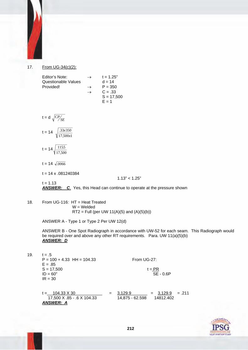
212
17. From UG-34(c)(2): Editor’s Note: → t = 1.25” Questionable Values d = 14 Provided! → P = 350 → C = .33 S = 17,500 E = 1 t = d CP
SE
t = 14 .,
33 35017 500 1
xx
t = 14 115517 500
.,
t = 14 .0066 t = 14 x .081240384 1.13” < 1.25” t = 1.13 ANSWER: C. Yes, this Head can continue to operate at the pressure shown 18. From UG-116: HT = Heat Treated W = Welded RT2 = Full (per UW 11(A)(5) and (A)(5)(b)) ANSWER A - Type 1 or Type 2 Per UW 12(d)
ANSWER B - One Spot Radiograph in accordance with UW-52 for each seam. This Radiograph would be required over and above any other RT requirements. Para. UW 11(a)(5)(b)
ANSWER: D 19. t = .5 P = 100 + 4.33 HH = 104.33 From UG-27: E = .85 S = 17,500 t = PR ID = 60" SE - 0.6P IR = 30 t = 104.33 X 30 = 3,129.9 = 3,129.9 = .211 17,500 X .85 - .6 X 104.33 14,875 - 62.598 14812.402 ANSWER: A

213
20. t = .5 P = 100 + 4.33 HH = 104.33 From UG - 32: E = 1.0 S = 17,500 t = PD ID = 60 2SE - 0.2P IR = 30 t = 104.33 X 60 = 6,259.8 = 6,259.8 = .179 2 X 17,500 X 1.0 - .2 X 104.33 35,000 - 20,866 34,979.134 ANSWER: C 21. t = .5 P = 100 + 4.33 HH = 104.33 From UG-32(f) S = 17,500 E = .85 t = PL L = 30" 2SE - 0.2P ID = 60" t = 104.33 X 30 = 3,129.9 = 3,129.9 = .105" 2 X 17,500 X .85 - .2 X 104.33 29,750 - 20.866 29,729.134 ANSWER: D 22. Shell Heads t = .375 - .250 = .125 t = .375" - .250 = .125 ID = 96" P = ? IR = 48" S = 12,100 S = 12,100 L = ICR = OD of skirt = 96.75" - .500 = 96.25 P = ? E = 1.0 E = 1.0 Shell: From UG-27 Heads: From UG-32
Shell: P = 12 100 1 12548 6 125, .
. .x xx+
Heads: P = 12 100 1 125885 96 25 1 125
, .. . . .
x xx x+
P = 1512 548 075
..
P = 1512 585301
..
P = 31.46 psig P = 17.731 Answer = 17.731 psig ANSWER: C

214
23. t = ? From UG-34 t = d CP SE/ D = 24 P = 250 t = 24 .17 X 250 S = 17,500 17,500 X 1 E = 1.0 C = .17 t = 24 42.5 17,500 t = 24 .0024285 t= 24 X .04592 t= 1.182" ANSWER ANSWER: A 24. t = ? From UG-34 d = 24 D =36 t = d ZCP SE/ S = 17,500 E = 1.0 Z = 3.4 - 2.4 X 24 Z = 1.8 36 C = .17 P = 250 Z = 3.4 - 1.6 Z = 1.8 t = 24 1.8 X .17 X 250 17,500 X 1 t = 24 76.5 17,500 t = 24 X .0661 t = 1.586 ANSWER ANSWER: B

215
25. d = 16 + 0.375 – 0.290 = 0.085 0.085 x 2 = 0.170 = 16 + 0.170 = 16.170 tr = .890 trn = .290 tn = .375 t = 1.0 From UG-36 A = 16.170 x .890 x 1 + 0 A = 14.39 ← A 1 = 16.170 X (1-.890) - 0 A 1 = 1.77 ← or A 1 = 2(1.375)(.11) = .302 A 2 = 5(.085) x 1 = .425 or A 2 = 5(.085) x .375 = .159 ← A 3 = 0 A 41 = .5 2 = .25 ← A 43 = 0 A 1 = 1.77 + A 2 = .159 + A 3 = 0 + A 41 = .25 + A 43 = 0 __________ 2.169 < 14.39 Yes need repad ANSWER: B 26. Parallel = 16’ or 8 + .375” + 1” Larger value - use 16” Perpendicular = 2.5 x 1 or 2.5 x .375 + 0 Use smaller value - use .9375 ANSWER: D

216
27. 1. Set Nomenclature and compute “tr” and “trn”: d = 18 tr = .287 trn = .103 tn = .280" t = .350 f = 1.0 E1 = 1.0 fr1 = fr4 = 1.0 te = .375 Dp = 24
tr = 200 2547500 1 6 200
xx x−.
tr = 5000
17 380,
tr = .287 trn = 200 9
17 500 1 6 200x
x x, .−
trn = 180017380
trn = .103
2.Compute “A”: A = 18 X .287 X 1 + 0 A = 5.166 3.Compute A1: A1 = 18 (1 X .350 - 1 X .287) - 0 A1 = 1.13 OR USE LARGER VALUE A1 = 2 (.350 + .280)(.350 - .287) -0 = 2 X .63 X .063 - 0 = .079 4.Compute A2: A2 = 5(.280 - .103) X 1 X .350 A2 = .309 OR USE SMALLER VALUE A2 = 2(.280 - .103) X (2.5 X .280 + .375) X 1 = .885 X 1.075 A2 = .380
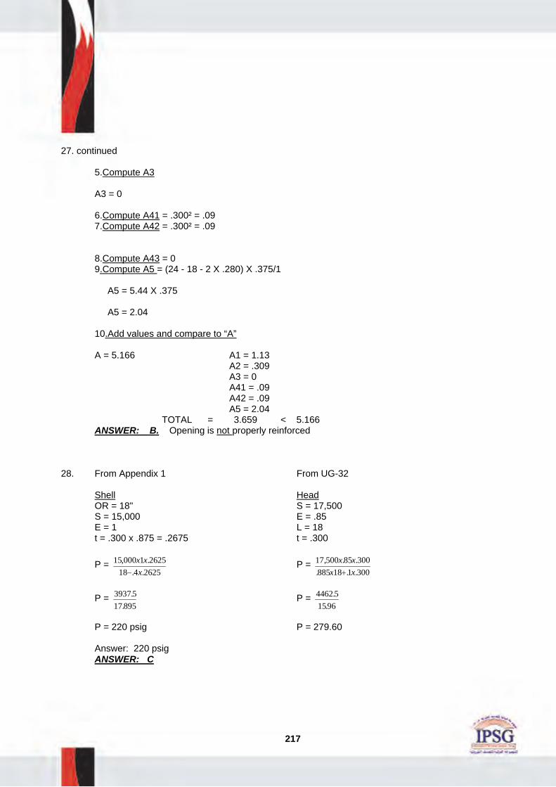
217
27. continued 5.Compute A3 A3 = 0 6.Compute A41 = .300² = .09 7.Compute A42 = .300² = .09 8.Compute A43 = 0 9.Compute A5 = (24 - 18 - 2 X .280) X .375/1 A5 = 5.44 X .375 A5 = 2.04 10.Add values and compare to “A” A = 5.166 A1 = 1.13 A2 = .309 A3 = 0 A41 = .09 A42 = .09 A5 = 2.04 TOTAL = 3.659 < 5.166 ANSWER: B. Opening is not properly reinforced 28. From Appendix 1 From UG-32 Shell Head OR = 18" S = 17,500 S = 15,000 E = .85 E = 1 L = 18 t = .300 x .875 = .2675 t = .300
P = 15 000 1 262518 4 2625, .
. .x xx−
P = 17 500 85 300885 18 1 300
, . .. . .
x xx x+
P = 3937 517 895
..
P = 4462 51596
..
P = 220 psig P = 279.60 Answer: 220 psig ANSWER: C

218
29. UG-99 Stress value of SA516 70 @ 70° = 17,500 = 2.6 @ 900° = 6,500 OR Stress value of SA 240 type 304 18,800 @ 70° = 1.27 use lowest 14,700 @ 900° value 1.3 X 1000 X 1.27 = 1,651 + HH 8.66 1,659.66 psig on bottom head ANSWER: D 30. From UG-28 From Fig. G = .002 (Factor A) From Fig. CS-2 = 11,800 (Factor B) DO = 24" t = .500 From UG-28 = Pa = 4B L = 48" 3(Do/t) Dot = 48 L/Do =2 = 4 X 11,800 = 47,200 = 372.77 Temp - 500 °F 3 X 48 144 Yield = 40,000 Pa = 327.77 psig ANSWER: A 31. SA 516 GR 70 is Curve “D” material Curve D 3.0" thick material is good for +10° per UGS-66(figure) + 10°F < 30°F, which is vessel rating Answer: No, does not require impact tests ANSWER: B
32. LTCR = . .637 5099−
LTCR = .014” Year
STCR = . .607 5093−
STCR = .030” Year
RL = . ..
509 411030− = 3.26 years
ANSWER: C

219
33. t = 80 X 12 16,800 X .85 - .6 X 80 1. .067" 2. 12" t = 960 3. 10YEARS 14.280 - 48 t = .067 Corrosion Rate = .008 per year Avg. = .283 - .067 = .216 Corrosion Allowance = .216 Remaining Life = 27 years - default to 10 years per API 510 ANSWER: A 34. A. Metal Loss = .250 B. Corrosion Rate = .0625 per year C. Corrosion Allowance = .125 D. Remaining Life = 2 yrs E. Inspection Interval = 2 yrs per API 510 35. From UG-27 t = ? P = 300 R = 40 E = 1 S = 12,100 t = 300 40
12 100 1 6 300x
x x, .−
t = 12 00012 100 180
,, −
t = 12 000
11 920,,
t = 1.006” required ANSWER: B

220
36. From Appendix 1 P = 600 + HH HH = 25 x .433 = 10.825 P = 610.825 E = .80 R o = 35 S = 15,000 t = 610825 35
15 000 80 4 610825.
, . . .x
x x+
t = 21378875
12 000 244 33.
, .+
t = 2137887512244 33
..
t = 1.746” ANSWER: D 37. From UG-32 P = ? t = .250 D = 45 S = 13,800 E = 1.0
P = 2 13 800 1 25045 2 250
x x xx
, .. .+
P = 69004505.
P = 153.16 psig ANSWER: B

221
38. From UG-32 P = ? t = .375” S = 14,500 L = 80.75 (L= O.D. @ skirt) E = .85
P = 14 500 85 375885 80 75 1 375
, . .. . . .
x xx x+
P = 462187572 463 0375
.. .+
P = 64 PSI ANSWER: C 39. From UG-27 P = ? t = .375 X .875 = .328 S = 15,000 E = 1.0 R = 12
P = 15 000 1 32812 6 328, .
. .x xx+
P = 492012196.
P = 403 psi ANSWER: A 40. From UW-16(b) tc = 1/4” or .7t min (smaller) t min = 3/4” or .500”/1.00” smaller - use .500 .7 x .500 = .350” or .250” - use .250” throat .250 x 1.414 = .353” leg ANSWER: C

222
41. From Fig. UW-16.1 Sketch (I) t 1 = .125 t 2 = .125 t 1 + t 2 = .250” t min = 3/4” or .350/.500” (smaller) t min = .350” 1.25 x .350” = .4375” required, .250” actual t 1 or t 2 not less than smaller of .250” or (.7 x .350) = .245” → .125 < .245 ANSWER: B 42. From UG-37 d = 10 tr = .490 t = .750 tn = .280 trn = .160 A = 10 x .490 = 4.9 A 1 = 10(.750 - .490) = 2.6 or 2(.750 + .280)(.75 - .49) = .53 A 2 = 5(.280 - .160).750 = .45 0r 5(.280 - .160).280 = .168 A 3 =0 A 41 = (.75 x 1.414). 2 = 1.124 A 43 = 0 2.6 + .168 + 1.124 = 3.892” 4.9” required > 3.892” actual Reinforcement is required. ANSWER: A

223
43. From UG-99 P = 350 HH = 21.65 St/SD = 1.09
1.3 x MAWP x StSD
⎛⎝⎜
⎞⎠⎟
+ H.H. =
H.H. = 50 x .433 = 21.65 SA 516 70 @ 750°F = 14,800 SA285 A @ 750°F = 10.300 SA53 B @ 750°F = 13,000 @ 70°F = 17,500 @ 70°F = 11,300 @ 70°F = 15,000 17,500
14 800, = 1.18 11 300
10 300,,
= 1.09 15 00013 000
,,
= 1.15
Use lowest ratio - use 1.09 1.3 x 350 x 1.09 + 21.65 = 517.6 or 518 psig ANSWER: C 44. From UG-100
1.1 x MAWP x StSD
P = 200
StSD
= 1.05
SA 515-65 @ 700°F = 15,500 SA 240 T 304 @ 700°F = 16,800 @ 70°F = 16,300 @ 70°F = 18,000 16 300
15 500,,
= 1.05 18 00016 800
,,
= 1.07
1.1 x 200 x 1.05 = 231 ANSWER: A

224
45. From UG-34 d = 20 C = .17 P = 300 S = 17,500 E = 1
t = 20 .,
17 30017 500 1
xx
t = 20 .002914286 t = 1.07 ANSWER: D 46. From UG-34 t = ? C = .33 d = 30 E = .85 S = 15,000 P = 375
t = 30 ., .33 375
15 000 85x
x
t = 30 1237512750
.
t = 30 x .098518437 t = 2.955” ANSWER: C 47. From UG -28 and External Pressure Charts: D o =48” t = .500” L = 84” y = 28,000 T = 600°F D o /t = 96 L/ D o =1.75

225
47.continued From Fig. G (External Pressure Charts): Factor A = .0008 From Fig. CS-1 (External Pressure Charts): Factor B = 7,000 From UG-28 Pa = 4 x 7000 = 28000 = 97.2 psi 3 x 96 288 ANSWER: A 48. From UG-20(f) and UCS-66:
• Not exempt per UG-20(f) • From UCS-66 - SA 662 Grade A - Curve C @ -30°F (.375”) = -50°F
SA 182 GR. 21 (Norm) - Curve C @ -30°F (.375”) = -50°F SA 516 - 70 - Curve B @ -30°F (.375”) = -20°F ANSWER: D 49. From UG-20(f) - not exempted @ -40°F
From UCS-66 SA 516-70 - Curve B @ .500” thick = -7°F > -40°F. Vessel requires impact testing ANSWER: A 50. A. .753 - .500 = .253” B. .253”/5 = .050” per year C. .500” - .350” = .150” D. .150”/.050” = 3 E. 2 years per API 510 51. From UG-27 tr = ? P = 150 S = 17,500 E = 1.0 R = 40 t = 150 40
17 500 1 6 150x
x x, .−
t = 600017410

226
51.continued t = .344” 1.0” - .344” = .656 .656/.125 = 5.24 years ANSWER: A
52. From UG-99 1.3 x MAWP x StSD
+ H.H.
H.H. = 150 x .433 = 64.95 or 65
1.3 x 150 x 1 + 65 = 260 psi ANSWER: D 53. From UG-32 P = 150 S = 17,500 E = 1.0 D = 60 + (1/4”) = 60.25 t = 150 60 25
2 17 500 1 2 150x
x x x.
, .−
t = 9037 535000 30
.−
t = .258” ANSWER: B 54. A. E = 1.0, UW-11(a)(5)(b) and UW-12(d) B. Category B, UW-3 C. Type 2, UW-12 Table 55. Top Head Bottom Head Shell #1 Shell #2 Nozzle #1 Nozzle #2
. ..
300 12501− . .
.270 125
006− . .
.270 125
003− . .
.200 125
015− . .
.150 125
023− . .
.230 125
004−
17.5 years 24.16 years 48.33 years 5 years 1 year 26.85 years

227
56. From API 510 - C/R = .012” per year x 2 = .144 metal loss at next inspection (twice). .788 - .144 = .688” remaining thickness at next inspection. From UG-27 -
P = 16 800 85 6882375 0 6 688
, . .. . .
X Xx+
= 9824 6424162
..
= 406.6 psi
P = 406.6 - Pressure or Inspection Interval is acceptable for conditions indicated. ANSWER: A 57. From API 510 Para. 7.2.11 - 75/60 = 1.25, 1.25 x (.195) = .243” ANSWER: D
58. From API 510 – C/R = . .407 3705− = .007” per year
.007 x 10 x 2 = .14” metal loss at next inspection (twice). .370 - .14 = .23” remaining thickness at next inspection.
From UG-27 - P = 17 100 90 2336 0 6 23, . .
. .x x
x+ = 3539 7
36138.
. = 97.9 or 98 psi
ANSWER: A