anfis controlled plug-in hybrid electric...
TRANSCRIPT

International Journal of Science, Engineering and Technology Research (IJSETR)
Volume 6, Issue 11, November 2017, ISSN: 2278 -7798
1492 All Rights Reserved © 2017 IJSETR
ANFIS CONTROLLED PLUG-IN HYBRID ELECTRIC VEHICLE
1G.Varshith
2B.Pavan Kumar Reddy
3B.Kavya Sree Reddy
1Graduate in Electrical & Electronics Engineering, Sree Vidyanikethan Engineering College
2Post Graduate in Power Electronics & Electrical Drives
3Graduate in Electrical & Electronics Engineering, National Institute of Technology, Puducherry
Abstract
Hybrid Electric vehicle (HEV) technology gives a
viable answer for accomplishing higher fuel
economy and better exhibitions with diminished
green house gas emissions. For Electric vehicle
applications, Switched reluctance motor (SRM) is
the best reasonable one of all the accessible motors.
To increase the driving miles of the electric vehicles,
a photovoltaic (PV) panel is mounted alongside on-
board battery bank. A tri-port converter with
Adaptive Neuro Fuzzy Inference controller (ANFIS)
is proposed in this paper to control the energy flow
between the PV panel, battery and SRM drive. Six
operational modes are introduced, four of which are
produced for driving modes and rest two for stop on-
board charging. In driving modes, the Perturb and
watch system is utilized so as to get greatest power
from the PV panel. In standstill charging modes, a
matrix associated charging topology is created with
no outside equipment. A multi area charging control
procedure is utilized adversary viable use of vitality
if there should be an occurrence of battery charging
from PV panel straightforwardly. The proposed tri
port technology with Adaptive Neuro Fuzzy
Inference controller (ANFIS) is developed in
MATLAB/SIMULINKenvironment and the
results are proven to be successful in producing
reduced harmonic distortion and have the
capability to make better market for electric
vehicle in the nearby future.
Index Terms - Electric Vehicles, Photovoltaic (PV), Switched Reluctance Motors (SRMs), Tri-
Port Converter, Perturb and Observe Technique,
Adaptive Neuro fuzzy Inference Controller.
I. INTRODUCTION
Electric vehicles have taken a significant
leap forward, by advances in motor drives,
power converters, batteries andenergy
management systems [1]-[4]. Be that as it may, due to thelimitation of current battery
technologies, the driving miles is moderately
short that limits the wide utilization of EVs [5]-[7]. In terms of motor drives, high-performance
permanent-magnet (PM) machines are generally
utilized while rare-earth materials are required in
large quantities, restricting the wide utilization of EVs. Keeping in mind the end goal to defeat
these issues, a photovoltaic panel and a switched
reluctance motor (SRM) are introduced with give power supply and motor drive, respectively.
Firstly, by including the PV panel on top of the
EV, a sustainable energy source isachieved. Nowadays, a typical passenger car has a surface
enough to install a 250-W PV panel. Second, a
SRM needs no rare-earth PMs and is additionally
robust so it gets increasing attention in EV applications. While PV panels have low power
density for traction drives, they can be used to
charge batteries the greater part of time. For the most part, the PV-fed EV has a comparable
structure to the hybrid electrical vehicle, whose
internal combustion engine(ICE) is supplanted
by the PV panel. The PV-fed EV system is outlined in Fig. 1. Its key components include an
off-board charging station, a PV, batteries and
power converters. In order to decrease the energy conversion processes, one approach is to upgrade
the motor to include some on-board charging
functions. For example, paper designs a 20-kW split-phase PM motor for EV charging, yet it
endures from high harmonic contents in the back
electromotive drive (EMF). Another solution
depends on a traditional SRM. Paper achieves on-board charging and power factor correction in

International Journal of Science, Engineering and Technology Research (IJSETR)
Volume 6, Issue 11, November 2017, ISSN: 2278 -7798
1493 All Rights Reserved © 2017 IJSETR
a 2.3-kW SRM by utilizing machine windings as
the input filter inductor. The concept of modular structure of driving topology is proposed in
paper. Based on intelligent power modules
(IPM), a four-phase half bridge converter is
utilized to achieve driving and grid-charging. In spite of the fact that modularization supports
mass production, the utilization of half/full
bridge topology reduces the system reliability (e.g. shoot-through issues). Paper builds up a
basic topology for plug-in hybrid electrical
vehicle (HEV) that supports flexible energy flow. In any case, for grid charging, the grid
should be associated with the generator rectifier
that builds the energy conversion process and
decreases the charging efficiency. In any case, a powerful topology and control strategy for PV-
fed EVs is not yet developed. Since the PV has
different characteristics to ICEs, the maximum power point tracking (MPPT) and solar energy
utilization are the unique factors for the PV-fed
EVs.
Fig. 1 PV-fed hybrid electrical vehicle.
In order to achieve low cost and flexible energy
flow modes, a low cost tri-port converter is
proposed in this paper to arrange the PV panel,
SRM and battery. Six operational modes are developed to support flexible control of energy
flow.
II. TOPOLOGY AND OPERATIONAL
MODES
A. Proposed topology and working modes The proposed Tri-port topology has three
energy terminals, PV, battery and SRM. They are
linked by a power converter which comprises of
four switching devices (S0~S3), four diodes (D0~D3) and two relays, as appeared in Fig. 2
[26]. By controlling relays J1 and J2, the six
operation modes are upheld, as appeared in Fig. 3; the corresponding relay activities are
delineated in Table I. In mode 1, PV is the
energy source to drive the SRM and to charge
the battery. In mode 2, the PV and battery are both the energy sources to drive the SRM. In
mode 3, the PV is the source and the battery is
idle. In mode 4, the battery is the driving source and the PV is idle. In mode 5, the battery is
charged by a single-phase grid while both the PV
and SRM are idle. In mode 6, the battery is charged by the PV and the SRM is idle.
Fig. 2. The proposed Tri-port topology for
PV-powered SRM drive.
Fig. 3. Six operation modes of the
proposed Tri-port topology.
International Journal of Science, Engineering and Technology Research (IJSETR)
Volume 6, Issue 11, November 2017, ISSN: 2278 -7798
1494 All Rights Reserved © 2017 IJSETR
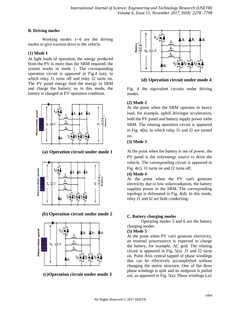
B. Driving modes
Working modes 1~4 are the driving
modes to give traction drive to the vehicle.
(1) Mode 1
At light loads of operation, the energy produced
from the PV is more than the SRM required; the system works in mode 1. The corresponding
operation circuit is appeared in Fig.4 (an), in
which relay J1 turns off and relay J2 turns on.
The PV panel energy feed the energy to SRM and charge the battery; so in this mode, the
battery is charged in EV operation condition.
(a) Operation circuit under mode 1
(b) Operation circuit under mode 2
(c) Operation circuit under mode 3
(d) Operation circuit under mode 4
Fig. 4 the equivalent circuits under driving
modes.
(2) Mode 2
At the point when the SRM operates in heavy
load, for example, uphill drivingor acceleration,
both the PV panel and battery supply power tothe
SRM. The relating operation circuit is appeared
in Fig. 4(b), in which relay J1 and J2 are turned
on.
(3) Mode 3
At the point when the battery is out of power, the
PV panel is the onlyenergy source to drive the
vehicle. The corresponding circuit is appeared in
Fig. 4(c). J1 turns on and J2 turns off.
(4) Mode 4 At the point when the PV can't generate
electricity due to low solarirradiation, the battery
supplies power to the SRM. The corresponding topology is delineated in Fig. 4(d). In this mode,
relay J1 and J2 are both conducting.
C. Battery charging modes
Operating modes 5 and 6 are the battery charging modes.
(5) Mode 5
At the point when PV can't generate electricity, an external powersource is expected to charge
the battery, for example, AC grid. The relating
circuit is appeared in Fig. 5(a). J1 and J2 turns
on. Point Anis central tapped of phase windings that can be effectively accomplished without
changing the motor structure. One of the three
phase windings is split and its midpoint is pulled out, as appeared in Fig. 5(a). Phase windings La1

International Journal of Science, Engineering and Technology Research (IJSETR)
Volume 6, Issue 11, November 2017, ISSN: 2278 -7798
1495 All Rights Reserved © 2017 IJSETR
and La2 are employed as inputfilter inductors.
These inductors are a part of the drive circuit to form an AC-DC rectifier for grid charging.
(6) Mode 6
At the point when the EV is stopped under
the sun, the PV can charge the battery. J1
turns off; J2 turns on. The relating charging
circuit is appeared in Fig. 5(b).
(a) Grid charging mode
(b) PV source charging mode
Fig. 5 Equivalent circuits of charging
condition modes.
III. CONTROL STRATEGY UNDER
DIFFERENT MODES
In order to make the best utilization of sun oriented energy for driving the EV, a control
strategy under various modes is planned.
A. Single source driving mode As indicated by the distinction in the
power sources, there are PV-driving; battery-
driving and PV and battery parallel fed source. In a heavy load condition, the PV power can’t
support the EV, mode 2 can be adopted to
support enough energy and make full utilization
of solar energy. Fig. 6(a) demonstrates the equivalent power source; the corresponding PV
panel working points is represented in Fig. 6(b).
Since the PV is paralleled with the battery, the
PV panel voltage is clamped to the battery
voltage UB. In mode 2, there are three working states: winding excitation, energy recycling and
freewheeling states, as appeared in Fig. 7. Modes
3 and 4 have comparable working states to mode
2. The difference is that the PV is the only source in mode 3 while the battery is the only source in
mode 4.
(a) Compound power source
(b) Working point of the PV
Fig. 6 Power supply at mode 2.
(a) Winding excitation state

International Journal of Science, Engineering and Technology Research (IJSETR)
Volume 6, Issue 11, November 2017, ISSN: 2278 -7798
1496 All Rights Reserved © 2017 IJSETR
(b) Energy recycling state
(c) Freewheeling state
Fig. 7 Working states at mode 2.
Neglecting the voltage drop over the power
switches and diodes, the phase voltage is given by
(1)
where Uin is the DC-link voltage, k is phase a, b,
or c, Rk is the phase resistance, ik is the phase current, Lk is the phase inductance, θr is the rotor
position, ψ(ik, θr) is the phase flux linkage
depending upon the phase current and rotor
position, and ωr is the angular speed.
The third term in Eq. 1 is the back electromotive
force (EMF) voltage by
(2)
Consequently, the phase voltage is found by
(3)
In the excitation area, turning on S0 and S1 will
induce a current in phase a winding, as show in
Fig. 7(a). Phase a winding is subjected to the positive DC bus voltage.
(4)
At the point when S0 is off and S1 is on, the phase current is in a freewheeling state in a zero
voltage loop, as appeared in Fig. 7(c), the phase
voltage is zero.
(5)
In the demagnetization region, S0 and S1 are
both turned off; what's more, the phase current
will flow back to the power supply, as appear in
Fig. 7(b). In this state, the phase winding is
subjected to the negative DC bus voltage, and the
phase voltage is
(6)
In single source driving mode, the voltage-PWM
control is utilized as the fundamental plan, as showed in Fig. 8. As per the given speed ω*, the
voltage-PWM control is activated at speed
control.
Fig. 8. SRM control strategy under single
source driving mode.

International Journal of Science, Engineering and Technology Research (IJSETR)
Volume 6, Issue 11, November 2017, ISSN: 2278 -7798
1497 All Rights Reserved © 2017 IJSETR
B. Driving-charging hybrid control
strategy
In the driving-charging hybrid control,
the PV is the driving source and the battery is
charged by the freewheeling current, as
represented in drive mode 1. There are two
control targets: maximum power point tracking
(MPPT) of the PV panel and speed control of the
SRM. The dual-source condition is switched
from a PV-driving mode. Firstly, the motor
speed is controlled at a given speed in mode 3.
At that point, J2 is turned on and J1 is off to
switch to mode 1. By controlling the turn-off
point, the maximum power of PV panel can be
tracked. There are three steady working states for
the double source (mode 1), as appeared in Fig.
9. In Fig. 9(a), S0 and S1 conduct, the PV panel
charges the SRM winding to drive the motor; In
Fig. 9(b), S0 and S1 turn off; and the battery is
charged with freewheeling current of the phase
winding. Fig. 9(c) appears a freewheeling state.
(a) Winding exciting state
(b) Battery charging state
(c).Freewheeling state
Fig. 9 Mode 1 working states.
Fig.10 is the control strategy under driving-charging mode. In Fig.10, θon is the turn on angle
of SRM; θoff is the turn-off angle of SRM. By
changing turn-on angle, the speed of SRM can be controlled; the maximum power point tracking of
PV panel can be achieved by adjusting turn-off
angle, which can control the charging current to
the battery.
Fig. 10. Control strategy under driving-
charging mode (mode 1)
C. Grid-charging control system
The proposed topology also supports the
single-phase grid charging. There are four fundamental charging states and S0 is
dependably turned off. At the point when the
grid instantaneous voltage is more than zero, the two working states are exhibited in Fig. 11(a)
and (b). In Fig. 11(a), S1 and S2 conduct, the
grid voltage charges the phase winding La2, the
relating condition can be communicated as Eq.7; In Fig. 11(b), S1 turns off and S2 conducts, the
grid is associated in series with phase winding to
charges the battery, the relating condition can be
communicated as Eq. 8. .
(7)
(8)

International Journal of Science, Engineering and Technology Research (IJSETR)
Volume 6, Issue 11, November 2017, ISSN: 2278 -7798
1498 All Rights Reserved © 2017 IJSETR
At the point when the grid instantaneous voltage
is below zero, the two working states are introduced in Fig. 11(c) and (d). In Fig. 11(c), S1
and S2 conduct, the grid voltage charges the
phase winding La1 and La2, the comparing
condition can be communicated as Eq. (9); In Fig. 11(d), S1 continues conducing and S2 turns
off, the grid is associated in series with phase
winding La1 and La2 to charges the battery, the relating condition can be communicated as Eq.
10.
(9)
(10)
(a) Grid charging state 1 (Ugrid>0)
(b) Grid charging state 2 (Ugrid>0)
(c) Grid charging state 3 (Ugrid<0)
(d) Grid charging state 4 (Ugrid<0)
Fig.11 Mode 5 charging states .
In Fig. 12, Ugrid is the grid voltage; by the phase lock loop (PLL), the phase data can be got;
Iref_grid is the given amplitude of the grid
current. Combining sinθ and Iref_grid, the instantaneous grid current reference iref_grid can
be figured. In this mode, when Ugrid> 0, the
inductance is La2; when Ugrid< 0, the
inductance is paralleled La1 and La2; so in order to adopt the change in the inductance, hysteresis
control is employed to acknowledge grid current
regulation. Besides, hysteresis control has great loop performance, global stability and small
phase lag that makes grid connected control
stable
Fig. 12 Grid-connected charging control
(Mode 5).
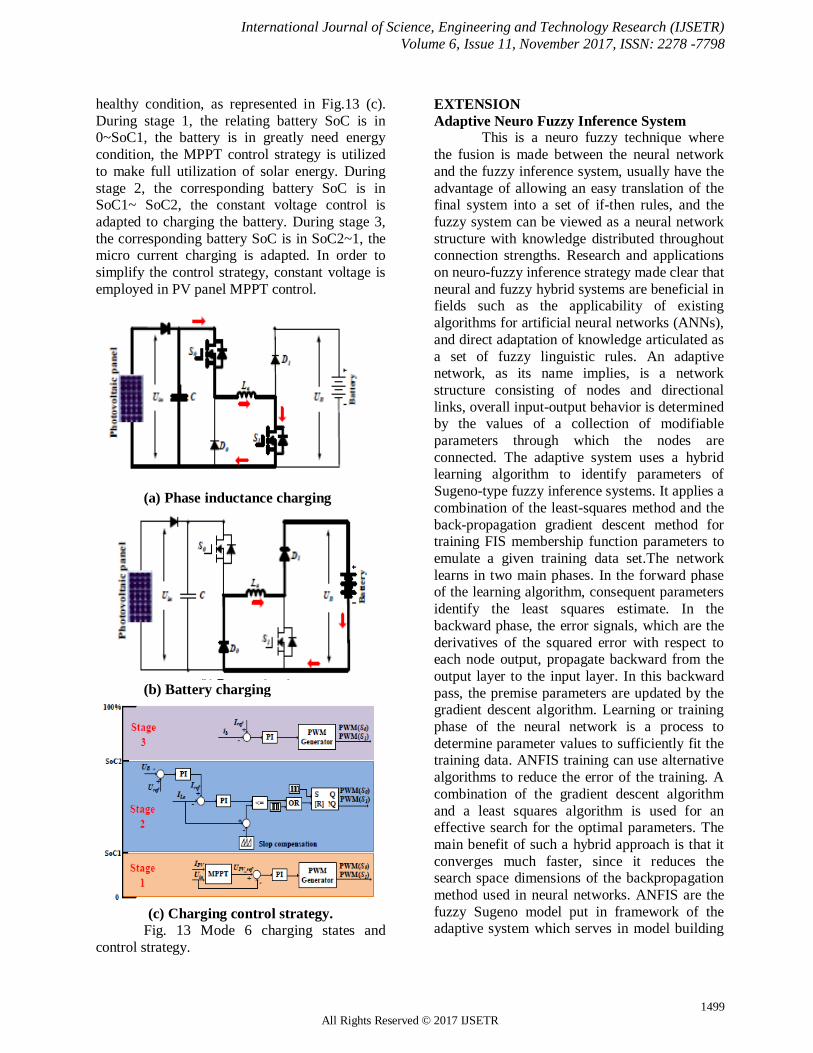
D. PV-fed charging control system
In this mode, the PV panel charges the
battery specifically by the driving topology. The
phase windings are employed as inductor; what's more, the driving topology can be worked as
interleaved Buckboost charging topology. For
one phase, there are two states, as appeared in
Fig. 13(a) and (b). Whenever S0 and S1 turn on, the PV panel charges phase inductance; when S0
and S1 turns off, the phase inductance discharges
energy to battery. According to the state-of-charging (SoC), there are three stages to make
full utilize of solar energy and keep up battery
International Journal of Science, Engineering and Technology Research (IJSETR)
Volume 6, Issue 11, November 2017, ISSN: 2278 -7798
1499 All Rights Reserved © 2017 IJSETR
healthy condition, as represented in Fig.13 (c).
During stage 1, the relating battery SoC is in 0~SoC1, the battery is in greatly need energy
condition, the MPPT control strategy is utilized
to make full utilization of solar energy. During
stage 2, the corresponding battery SoC is in SoC1~ SoC2, the constant voltage control is
adapted to charging the battery. During stage 3,
the corresponding battery SoC is in SoC2~1, the micro current charging is adapted. In order to
simplify the control strategy, constant voltage is
employed in PV panel MPPT control.
(a) Phase inductance charging
(b) Battery charging
(c) Charging control strategy.
Fig. 13 Mode 6 charging states and
control strategy.
EXTENSION
Adaptive Neuro Fuzzy Inference System This is a neuro fuzzy technique where
the fusion is made between the neural network
and the fuzzy inference system, usually have the
advantage of allowing an easy translation of the final system into a set of if-then rules, and the
fuzzy system can be viewed as a neural network
structure with knowledge distributed throughout connection strengths. Research and applications
on neuro-fuzzy inference strategy made clear that
neural and fuzzy hybrid systems are beneficial in fields such as the applicability of existing
algorithms for artificial neural networks (ANNs),
and direct adaptation of knowledge articulated as
a set of fuzzy linguistic rules. An adaptive network, as its name implies, is a network
structure consisting of nodes and directional
links, overall input-output behavior is determined by the values of a collection of modifiable
parameters through which the nodes are
connected. The adaptive system uses a hybrid learning algorithm to identify parameters of
Sugeno-type fuzzy inference systems. It applies a
combination of the least-squares method and the
back-propagation gradient descent method for training FIS membership function parameters to
emulate a given training data set.The network
learns in two main phases. In the forward phase of the learning algorithm, consequent parameters
identify the least squares estimate. In the
backward phase, the error signals, which are the
derivatives of the squared error with respect to each node output, propagate backward from the
output layer to the input layer. In this backward
pass, the premise parameters are updated by the gradient descent algorithm. Learning or training
phase of the neural network is a process to
determine parameter values to sufficiently fit the training data. ANFIS training can use alternative
algorithms to reduce the error of the training. A
combination of the gradient descent algorithm
and a least squares algorithm is used for an effective search for the optimal parameters. The
main benefit of such a hybrid approach is that it
converges much faster, since it reduces the search space dimensions of the backpropagation
method used in neural networks. ANFIS are the
fuzzy Sugeno model put in framework of the adaptive system which serves in model building
International Journal of Science, Engineering and Technology Research (IJSETR)
Volume 6, Issue 11, November 2017, ISSN: 2278 -7798
1500 All Rights Reserved © 2017 IJSETR
and validation of developed model to facilitate
training and adaptation.
Fig. 14 Block diagram of the ANFIS
control scheme
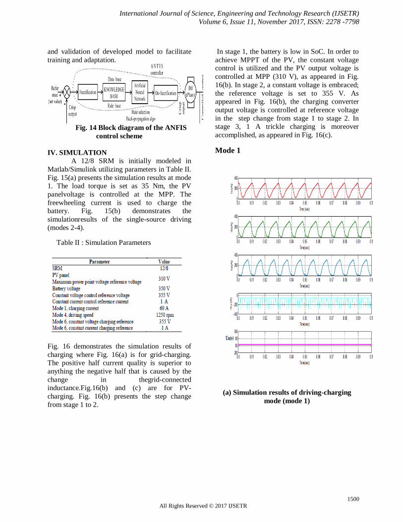
IV. SIMULATION
A 12/8 SRM is initially modeled in
Matlab/Simulink utilizing parameters in Table II.
Fig. 15(a) presents the simulation results at mode 1. The load torque is set as 35 Nm, the PV
panelvoltage is controlled at the MPP. The
freewheeling current is used to charge the battery. Fig. 15(b) demonstrates the
simulationresults of the single-source driving
(modes 2-4).
Table II : Simulation Parameters
Fig. 16 demonstrates the simulation results of
charging where Fig. 16(a) is for grid-charging. The positive half current quality is superior to
anything the negative half that is caused by the
change in thegrid-connected inductance.Fig.16(b) and (c) are for PV-
charging. Fig. 16(b) presents the step change
from stage 1 to 2.
In stage 1, the battery is low in SoC. In order to
achieve MPPT of the PV, the constant voltage control is utilized and the PV output voltage is
controlled at MPP (310 V), as appeared in Fig.
16(b). In stage 2, a constant voltage is embraced;
the reference voltage is set to 355 V. As appeared in Fig. 16(b), the charging converter
output voltage is controlled at reference voltage
in the step change from stage 1 to stage 2. In stage 3, 1 A trickle charging is moreover
accomplished, as appeared in Fig. 16(c).
Mode 1
(a) Simulation results of driving-charging
mode (mode 1)

International Journal of Science, Engineering and Technology Research (IJSETR)
Volume 6, Issue 11, November 2017, ISSN: 2278 -7798
1501 All Rights Reserved © 2017 IJSETR
Mode3
(b) Simulation results of single source driving
mode (modes 3)
Fig. 15 Simulation results for driving
conditions at modes 1, 3 and 4.
Mode 5
Mode6_Stage1
(b) PV charging mode 6 (stage 1)

International Journal of Science, Engineering and Technology Research (IJSETR)
Volume 6, Issue 11, November 2017, ISSN: 2278 -7798
1502 All Rights Reserved © 2017 IJSETR
Mode6_Stage2
(c) PV charging mode 6 (stage 2)
Mode6_Stage3
(d)PV charging mode 6 (stage 3)
Fig. 16 simulation results for charging modes.
Table III: THD values for Proposed and
Extension methods.
VI. CONCLUSION
In order to handle the range anxiety of
utilizing EVs and decrease the system cost, a mix of the PV panel and SRM is proposed as the EV
driving system.
The main contributions of this paper are:
(i) A Tri-port converter is utilized to associate
the PV panel, battery and SRM.
(ii) Six working modes are produced to accompli
sh adaptable energy stream for controlling the driving, charging and hybrid (i.e., mix of both
driving and charging) modes.
THD in % Existing
Method
THD in % Extension
Method
Mode 1:
Ia= 41.43, Ib =38.12,
Ic=64.58
Mode 1:
Ia= 25.72, Ib =19.82,
Ic=27.12
Mode 2:
Ia= 43, Ib =31.01,
Ic=71.52
Mode 2:
Ia= 26.66 , Ib =17.68 ,
Ic=30.04
Mode 3:
ILa= 82.66, ILb =33.68,
ILc=43.47
Mode 3:
ILa= 51.25, ILb =17.51,
ILc=18.26
Mode 4:
ILa= 64.68, ILb =34.25,
ILc=41.87
Mode 4:
ILa= 40.1, ILb =17.81,
ILc=17.58
Mode 5:
Ugrid =
0.004535,Igrid =0.00486
4
Mode 5:
Ugrid =
0.004535,Igrid =0.0048
64
Mode 6:stage 1
Ia= 11.5
Mode 6:stage 1
Ia= 4.091
Mode 6:stage 2
ILa= 2.377
Mode 6:stage 2
ILa= 0.9985
Mode 6:stage 1
Ia= 2.429,Ib=2.632
Mode 6:stage 3
Ia= 2.546,Ib=1.608

International Journal of Science, Engineering and Technology Research (IJSETR)
Volume 6, Issue 11, November 2017, ISSN: 2278 -7798
1503 All Rights Reserved © 2017 IJSETR
(iii) An exceptional charging topology is
proposed such that the vehicle can be charged from the grid with no outside power electronic
gadgets
(iv) Photo Voltaic encouraged battery charging
control game plan is created alongside irritate
and watch MPPT to propel the usage of sunlight
based energy.
(v) ANFIS controller is fused to control the
general operations and to lessen the aggregate consonant mutilations.
Since PV-fed EVs are a greener and more economical innovation than conventional ICE
vehicles, this work will give feasible solution to
reducing the total costs and CO2emissions of
electrified vehicles. Moreover, the proposed innovation may likewise be connected to
comparable applications, such asfuel cell
powered EVs. Fuel cells have a considerably higher power density and are hence more
qualified for EV applications.
REFERENCES
[1] A. Emadi, L. Young-Joo, K. Rajashekara,
“Power electronics and motor drives in electric,
hybrid electric, and plug-in hybrid electric vehicles,” IEEE Trans. Ind. Electron., vol. 55,
no. 6, pp. 2237-2245, Jun. 2008.
[2] B. l. K. Bose, “Global energy scenario and
impact of power electronics in 21st century,” IEEE Trans. Ind. Electron., vol. 60, no. 7, pp.
2638-2651, Jul. 2013.
[3] J. de Santiago, H. Bernhoff, B. Ekergård, S.
Eriksson, S. Ferhatovic, R. Waters, and M. Leijon,“Electrical motor drivelines in
commercial all-electric vehicles: a review,” IEEE
Trans. Veh. Technol., vol. 61, no. 2, pp. 475-484, Feb. 2012.
[4] Z. Amjadi, S. S. Williamson, “Power-
electronics-based solutions for plug-in hybrid
electric vehicle energy storage and management
systems,” IEEE Trans. Ind. Electron., vol. 57, no. 2, pp. 608-616, Feb. 2010.
[5] A. Kuperman, U. Levy, J. Goren, A.
Zafransky, and A. Savernin, “Battery charger for
electric vehicle traction battery switch station,”
IEEE Trans. Ind. Electron., vol. 60, no. 12, pp.
5391-5399, Dec. 2013.
Authors Biography:
Mr.G.Varshith from
Tirupathi, Andhra Pradesh
who has a zeal in research
participated in various
activites since childhood. He
is a Graduate in the Stream
of Electrical &
Electronics Engineering from
Sree Vidyanikethan Engineering College –
An Autonomous Institute affiliated to JNTU
Ananthapur.
Mr. B.Pavan Kumar Reddy
from Tirupathi, Andhra Pradesh completed his Graduation in the
stream of Electrical and
Electronics Engineering (EEE) from Sree Vidyanikethan
Engineering College in 2014. He
gained Practical knowledge by working as Maintenance Engineer at Amara Raja Batteries
Limited for a 15 Months and recently completed his
masters in Power Electronics and Electrical Drives
specialization from VEMU Institute of Technology – An ISO 2015:9001 certified institute affiliated to
JNTU Ananthapur.
Miss B.Kavya Sree Reddy from
Tirupathi, Andhra Pradesh had
shown her merit in many exams
conducted by various institutes
& stood top in them. Presently
pursuing her graduation in the
stream of Electrical & Electronics Engineering
from National Institute of Technology, Puducherr
y(NITPY).