alleviation of power fluctuations in wecs by different...
TRANSCRIPT

International Journal of Science, Engineering and Technology Research (IJSETR), Volume 4, Issue 1, January 2015
215
ISSN: 2278 – 7798 All Rights Reserved © 2015 IJSETR
Abstract—With worldwide increasing shares of electricity generated by wind energy conversion system (WECS) and their influence on the mains stability and contribution to reliable energy supply becomes more and more relevant. This paper compares the performance of different control methods for Wind energy converters, regarding their electrical power-output fluctuation at different wind conditions. The results shows the different types of mitigation methods for power fluctuations and their
corresponding results.
Index Terms— Bi-directional dc–dc converter,
Current source inverter, Dual inverter, Energy storage, Electric double-layer capacitor, Non-integer voltage ratio, Space vector modulation, Wind energy, Wind power generation.
I. INTRODUCTION
In an attempt to prevent the realization of fears about
the global warming, renewable energy sources has
experienced a huge face lift to generate the electricity.
However, the generated power from the renewable source
is always fluctuated due to an environmental status. In
order to prop up renewable energy and reimburse the
fluctuating power, an energy storage system is effective
one. Among that Wind power is the fastest growing
renewable energy source due to its improving
technologies and economical competitiveness. Generally,
the availability of wind energy supply cannot be
controlled like energy conversion from fossil fuels;
because, wind energy underlies a stochastic fluctuating
behavior. These fluctuations cause dynamic power
oscillations in the wind energy converter’s (WEC) power
drain. In particular, at locations with highly turbulent
Manuscript received Jan, 2015.
Anitha.N, Electrical and Electronics Engineering, Kumaraguru
College of Technology, (e-mail: [email protected]). Coimbatore, India.
Narmatha Lakshmi.S, Electrical and Electronics Engineering,
Kumaraguru College of Technology, Coimbatore, India, (e-mail: [email protected]).
Geethanjali.S, Electrical and Electronics Engineering, Kumaraguru
College of Technology, Coimbatore, India, (e-mail: [email protected]).
wind characteristics, critical load peaks might occur in the
WEC plant. They propagate from the wind rotor to the
connected electrical grid and cause premature damage in
mechanical components, thermal overloads in electrical
components, as well as voltage variations in the mains
power supply. Their grid impact increases with rising
connected power of single plants or wind parks [1].
Fig.1. General configuration of a variable-speed WEC
In principle, variable-speed WECs provide the
technical possibility to reduce the cumulative load in the
power drain and the influence on the mains power supply
grid. Therefore, specially designed automatic controls
and operation management are required to run the
appliance. The automatic controls are reference variable
controls, which set the system to the optimal operating
point. The main task of the operation management is to
force a power or rotor speed set point for the momentarily
operation condition. For the owner of WECs or wind
parks, the foremost interest is to sell as much energy as
possible regardless on their grid influence. At the same
time, the grid operator prefers a smooth power delivery to
keep the grid influence at a low level itself. Just in recent
years, more regulations have been passed to control the
grid influence from WEC’s.
In this paper two different methods are compared in
regard of their influence on the reduction of power
Alleviation of Power Fluctuations in WECS by
Different Control Methods
Anitha.N, Geethanjali.S , Narmatha Lakshmi.S

International Journal of Science, Engineering and Technology Research (IJSETR), Volume 4, Issue 1, January 2015
216
ISSN: 2278 – 7798 All Rights Reserved © 2015 IJSETR
fluctuation of the WEC’s. The control methods
considered in this investigation are direct integration of
battery energy storage systems , Electric double-layer
capacitor applied for energy storage system. These
control methods are described in Section III. Foremost,
the following section gives a short overview of the system
characteristics of WEC’s.
II. WIND ENERGY CONVERSION SYSTEM
The wind rotor converts the air mass’s kinetic energy
into mechanical (rotating) energy. The drive shaft
transfers this rotating energy to the electrical generator.
Most WECs system uses gear boxes to match the
operating speed of the wind rotor and the generator. The
electrical energy is then fed into the electrical grid. The
generator can be directly connected to the mains power
supply, or power converter systems can provide the
coupling of the generator and the electrical grid (Fig.
1)[1].
In addition, the application-specific requirements are
maximum energy yield, low influence on the grid, and
low strain/stress in the power drain. The air mass’s kinetic
energy has a specific power Pwind that is characterized
by the air mass density ρA, the surface area of the wind
flow AR, and the wind speed w. It can be described by the
following formula:
Pwind= ½ ρAAƦω3
(1)
Keep in mind the cubic influence of the wind speed on the
wind power.
To gain the maximum energy yield, the wind rotor has
to operate at highest efficiency. The aerodynamic
efficiency is expressed by the cP coefficient, which
determines the amount of power extracted (PRotor) from
the wind crossing the rotor area
CP= PRotor
PWind (2)
According to Betz, the maximum cP value is cP,Betz
=0.59. The efficiency of wind rotors strongly depends on
the airfoil angle of incidence. To take into account the
rotational speed of the wind rotor and the wind speed, the
resulting angle of incidence is indicated by λ. λ is called
the tip speed ratio and describes the relation of the wind
rotor tip speed to the wind Speed ,
λ=2ΠRnR
𝜔 (3)
where R is the rotor radius and nR is the rotor speed.
In order to gain advantage of this special
characteristic, the WEC must be able to operate at
variable speed [2]. This demands a special structure of the
generator grid coupling. The main task is the decoupling
of the generator rotational speed from the grid voltage
frequency. In Fig. 1, general configuration of a variable
speed WEC’s structure is shown, where a dc link
connects the generator to the grid.
III. CONTROL METHODS FOR WECs
A. Direct Integration of Battery Energy Storage Systems
(BESS) for WECs
A direct integration method, presents a new direct
integration scheme for BESS with the use of grid-side
inverter. It utilizes the popular dual inverter topology, as
shown in Fig.2, where two 2-level inverters are cascaded
through a coupling transformer. The two inverters are
named as the main inverter and the auxiliary inverter in
line with their modes of operation. A battery bank is
directly connected to the dc link of the auxiliary inverter
without interfacing dc–dc converter. Unlike the simple
direct connection topology, this system facilitates full
controllability over charging/ discharging currents and
voltage of the battery.
The main inverter operates at the fundamental
frequency producing square wave outputs. Harmonics of
the square wave output are compensated by the
high-speed auxiliary inverter. This particular frequency
splitting arrangement can reduce switching losses as well
as device ratings of the main inverter. Another advantage
of this system is its ability to produce up to 13 voltage
levels in the phase voltage waveform whereas the
traditional 2-level inverter can produce only five levels
[3] & [4].
Fig.2. Experimental setup used to verify the linear
relationship between main inverter dc-link voltage and
battery power.
Extensive research has been done on modulation and
control of the aforementioned dual inverter topology,
especially for motor drive applications [5]-[8]. They all
have considered cases where fixed-integer dc-link voltage
ratios are present. A pulse width modulation (PWM)
scheme for this dual inverter is explained in [9] for 1:1
and 1:2 voltage ratios. Although a power sharing
controller is proposed in for dynamically varying dc-link
voltages, it also assumes identical dc-link voltage
variations thus making the ratio to be 1:1. A hierarchical
International Journal of Science, Engineering and Technology Research (IJSETR), Volume 4, Issue 1, January 2015
217
ISSN: 2278 – 7798 All Rights Reserved © 2015 IJSETR
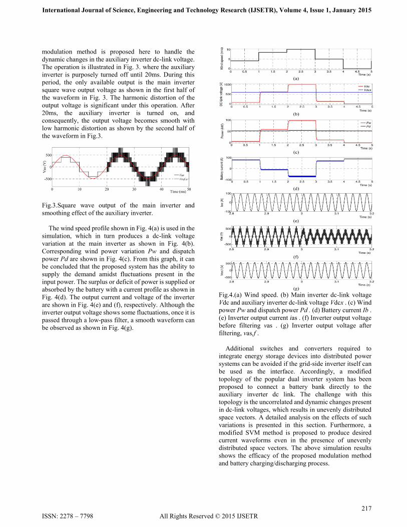
modulation method is proposed here to handle the
dynamic changes in the auxiliary inverter dc-link voltage.
The operation is illustrated in Fig. 3. where the auxiliary
inverter is purposely turned off until 20ms. During this
period, the only available output is the main inverter
square wave output voltage as shown in the first half of
the waveform in Fig. 3. The harmonic distortion of the
output voltage is significant under this operation. After
20ms, the auxiliary inverter is turned on, and
consequently, the output voltage becomes smooth with
low harmonic distortion as shown by the second half of
the waveform in Fig.3.
Fig.3.Square wave output of the main inverter and
smoothing effect of the auxiliary inverter.
The wind speed profile shown in Fig. 4(a) is used in the
simulation, which in turn produces a dc-link voltage
variation at the main inverter as shown in Fig. 4(b).
Corresponding wind power variation Pw and dispatch
power Pd are shown in Fig. 4(c). From this graph, it can
be concluded that the proposed system has the ability to
supply the demand amidst fluctuations present in the
input power. The surplus or deficit of power is supplied or
absorbed by the battery with a current profile as shown in
Fig. 4(d). The output current and voltage of the inverter
are shown in Fig. 4(e) and (f), respectively. Although the
inverter output voltage shows some fluctuations, once it is
passed through a low-pass filter, a smooth waveform can
be observed as shown in Fig. 4(g).
Fig.4.(a) Wind speed. (b) Main inverter dc-link voltage
Vdc and auxiliary inverter dc-link voltage Vdcx . (c) Wind
power Pw and dispatch power Pd . (d) Battery current Ib .
(e) Inverter output current ias . (f) Inverter output voltage
before filtering vas . (g) Inverter output voltage after
filtering, vas,f .
Additional switches and converters required to
integrate energy storage devices into distributed power
systems can be avoided if the grid-side inverter itself can
be used as the interface. Accordingly, a modified
topology of the popular dual inverter system has been
proposed to connect a battery bank directly to the
auxiliary inverter dc link. The challenge with this
topology is the uncorrelated and dynamic changes present
in dc-link voltages, which results in unevenly distributed
space vectors. A detailed analysis on the effects of such
variations is presented in this section. Furthermore, a
modified SVM method is proposed to produce desired
current waveforms even in the presence of unevenly
distributed space vectors. The above simulation results
shows the efficacy of the proposed modulation method
and battery charging/discharging process.

International Journal of Science, Engineering and Technology Research (IJSETR), Volume 4, Issue 1, January 2015
218
ISSN: 2278 – 7798 All Rights Reserved © 2015 IJSETR
B. Electric double-layer capacitor applied for energy
storage system
In recent years, an energy capacitor system (ECaSS)
connected an electric double-layer capacitor (EDLC) with
power electronics devices have been developed as energy
storage system [10]-[12] and applied in power
system[13]-[15]. An EDLC is a safer one and has a longer
service life than the secondary battery, and requires
virtually no maintenance, but having the following
disadvantages: the dielectric voltage-withstand level of a
EDLC-cell is 3 V or lower and high internal-resistive loss
is directly proportional to squared current. To overcome
these issues, though parallel-monitor limiting the
charging voltage is attached to each EDLC-cell, the price
brings on accordingly expensive. Also, a voltage-source
inverter (VSI) has been widely used for ECaSS. However,
VSI becomes increasingly difficult to regulate an output
power due to the voltage drop at terminal of EDLC-bank.
In this section the current-source ECaSS (CS-ECS) using
a current-source inverter (CSI) is used to resolve an issues
of ECaSS using VSI. CS-ECS has the several merits. For
example, the output regulation is possible even if a
decrease or a fluctuation in dc-voltage arises as stored
power discharges. Also, high internal-resistive loss of
EDLC-cell can be reduced by a bi-directional dc-dc
converter, regulating dc current, since EDLC-bank is
connected to ac-feeder through bi-directional dc-dc
converter.
Fig.5.(a) Circuit configuration of current source ECS. (b)
Pulse gate signals.
The circuit configuration and pulse gate signals for
CS-ECS is shown in Fig. 5. The CS-ECS consists of a
multilevel CSI (connected to two full-bridge inverter),
bi-directional dc-dc converter (four-quadrant dc-dc
converter: FQ dc-dc converter), and EDLC-bank. The CSI
is utilized to reduce harmonic components of ac-current.
Pulse gate signals (12 pulses) for the CSI are show in Fig.
5(b). In order to balance the shunt currents (idc1 and idc2)
of dc-current idc, pulse gate signals in
the period of 120◦ are alternately supplied to the
respectively arm devices (e.g., U-arm upper devices Up1
and Up2). As shown in Fig. 5(b), this procedure is
repeated periodically. Referring concurrently to Figs. 1(a)
and 2, EDLC-bank is stored with an electric energy
(charging mode) when a polarity of dc-voltage vdc is
positive, and discharging mode when the polarity is
negative, because the polarity of dc-current idc is always
positive. Fig. 6(a) shows a diagram of operating principle
for FQ dc–dc converter.
Fig.6(a).Operating quadrant of current-source inverter.

International Journal of Science, Engineering and Technology Research (IJSETR), Volume 4, Issue 1, January 2015
219
ISSN: 2278 – 7798 All Rights Reserved © 2015 IJSETR
Fig.6(b). Conceptual diagram of active and reactive power
control.
Conceptual diagram for active and reactive power control
can be expressed by d-q axes reference coordinate frame,
as shown in Fig. . In Fig.6(b). α is the phase and In is the
root mean square of ac-current. Since dc-current idc is
proportional to In in the Fig.6(b). the active and reactive
power (pe and qe) are controlled by α and idc.
Fig. 7. Simulation results of wind turbulence and EDLC-cell failure. (a) Wind speed, mechanical input torque and rotor speed.
(b) Tie-line power and system frequency. (c) WTG terminal d-q axes voltage. (d) Active and reactive output power of
CS-ECS. (e) DC-side quantities and stored power of CS-ECS.
International Journal of Science, Engineering and Technology Research (IJSETR), Volume 4, Issue 1, January 2015
220
All Rights Reserved © 2012 IJSETR
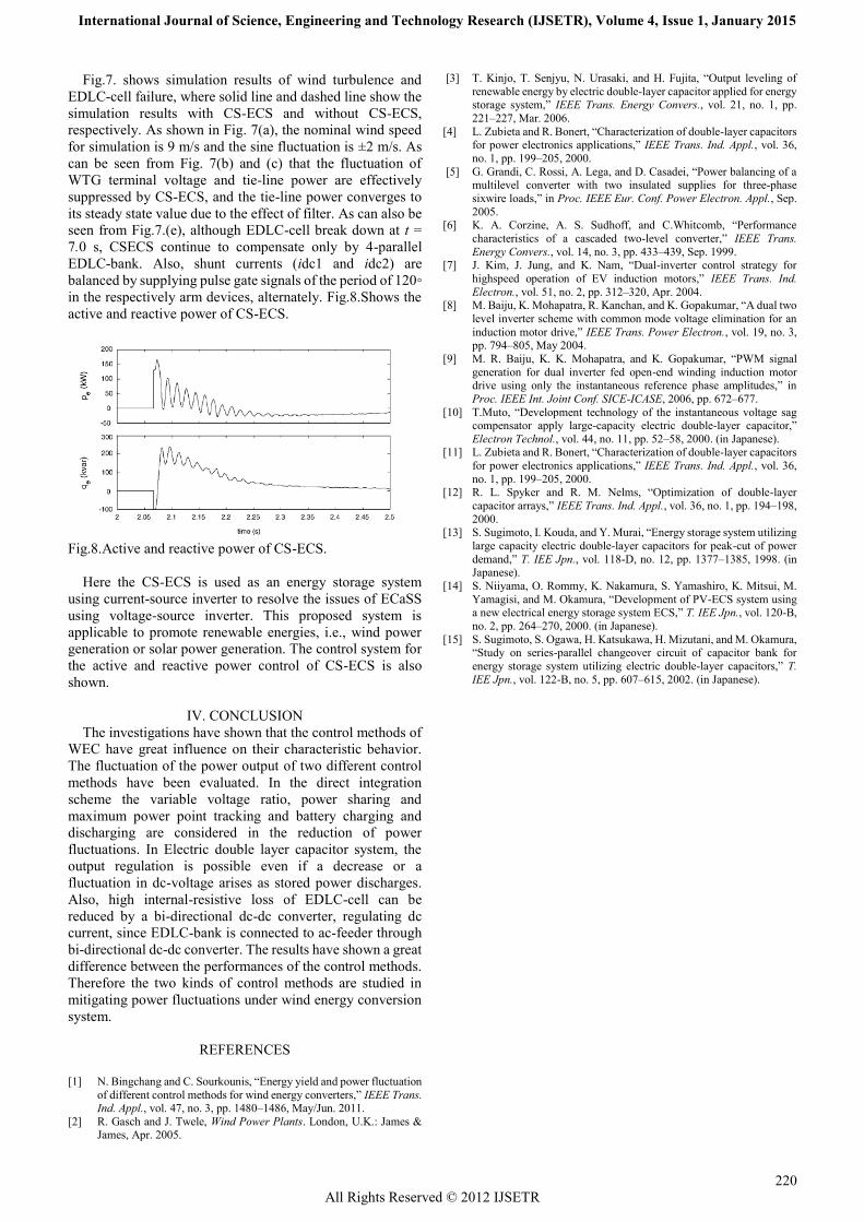
Fig.7. shows simulation results of wind turbulence and
EDLC-cell failure, where solid line and dashed line show the
simulation results with CS-ECS and without CS-ECS,
respectively. As shown in Fig. 7(a), the nominal wind speed
for simulation is 9 m/s and the sine fluctuation is ±2 m/s. As
can be seen from Fig. 7(b) and (c) that the fluctuation of
WTG terminal voltage and tie-line power are effectively
suppressed by CS-ECS, and the tie-line power converges to
its steady state value due to the effect of filter. As can also be
seen from Fig.7.(e), although EDLC-cell break down at t =
7.0 s, CSECS continue to compensate only by 4-parallel
EDLC-bank. Also, shunt currents (idc1 and idc2) are
balanced by supplying pulse gate signals of the period of 120◦
in the respectively arm devices, alternately. Fig.8.Shows the
active and reactive power of CS-ECS.
Fig.8.Active and reactive power of CS-ECS.
Here the CS-ECS is used as an energy storage system
using current-source inverter to resolve the issues of ECaSS
using voltage-source inverter. This proposed system is
applicable to promote renewable energies, i.e., wind power
generation or solar power generation. The control system for
the active and reactive power control of CS-ECS is also
shown.
IV. CONCLUSION
The investigations have shown that the control methods of
WEC have great influence on their characteristic behavior.
The fluctuation of the power output of two different control
methods have been evaluated. In the direct integration
scheme the variable voltage ratio, power sharing and
maximum power point tracking and battery charging and
discharging are considered in the reduction of power
fluctuations. In Electric double layer capacitor system, the
output regulation is possible even if a decrease or a
fluctuation in dc-voltage arises as stored power discharges.
Also, high internal-resistive loss of EDLC-cell can be
reduced by a bi-directional dc-dc converter, regulating dc
current, since EDLC-bank is connected to ac-feeder through
bi-directional dc-dc converter. The results have shown a great
difference between the performances of the control methods.
Therefore the two kinds of control methods are studied in
mitigating power fluctuations under wind energy conversion
system.
REFERENCES
[1] N. Bingchang and C. Sourkounis, ―Energy yield and power fluctuation
of different control methods for wind energy converters,‖ IEEE Trans. Ind. Appl., vol. 47, no. 3, pp. 1480–1486, May/Jun. 2011.
[2] R. Gasch and J. Twele, Wind Power Plants. London, U.K.: James & James, Apr. 2005.
[3] T. Kinjo, T. Senjyu, N. Urasaki, and H. Fujita, ―Output leveling of
renewable energy by electric double-layer capacitor applied for energy storage system,‖ IEEE Trans. Energy Convers., vol. 21, no. 1, pp.
221–227, Mar. 2006.
[4] L. Zubieta and R. Bonert, ―Characterization of double-layer capacitors for power electronics applications,‖ IEEE Trans. Ind. Appl., vol. 36,
no. 1, pp. 199–205, 2000.
[5] G. Grandi, C. Rossi, A. Lega, and D. Casadei, ―Power balancing of a multilevel converter with two insulated supplies for three-phase
sixwire loads,‖ in Proc. IEEE Eur. Conf. Power Electron. Appl., Sep.
2005. [6] K. A. Corzine, A. S. Sudhoff, and C.Whitcomb, ―Performance
characteristics of a cascaded two-level converter,‖ IEEE Trans.
Energy Convers., vol. 14, no. 3, pp. 433–439, Sep. 1999. [7] J. Kim, J. Jung, and K. Nam, ―Dual-inverter control strategy for
highspeed operation of EV induction motors,‖ IEEE Trans. Ind.
Electron., vol. 51, no. 2, pp. 312–320, Apr. 2004. [8] M. Baiju, K. Mohapatra, R. Kanchan, and K. Gopakumar, ―A dual two
level inverter scheme with common mode voltage elimination for an
induction motor drive,‖ IEEE Trans. Power Electron., vol. 19, no. 3, pp. 794–805, May 2004.
[9] M. R. Baiju, K. K. Mohapatra, and K. Gopakumar, ―PWM signal
generation for dual inverter fed open-end winding induction motor drive using only the instantaneous reference phase amplitudes,‖ in
Proc. IEEE Int. Joint Conf. SICE-ICASE, 2006, pp. 672–677.
[10] T.Muto, ―Development technology of the instantaneous voltage sag compensator apply large-capacity electric double-layer capacitor,‖
Electron Technol., vol. 44, no. 11, pp. 52–58, 2000. (in Japanese). [11] L. Zubieta and R. Bonert, ―Characterization of double-layer capacitors
for power electronics applications,‖ IEEE Trans. Ind. Appl., vol. 36,
no. 1, pp. 199–205, 2000. [12] R. L. Spyker and R. M. Nelms, ―Optimization of double-layer
capacitor arrays,‖ IEEE Trans. Ind. Appl., vol. 36, no. 1, pp. 194–198,
2000. [13] S. Sugimoto, I. Kouda, and Y. Murai, ―Energy storage system utilizing
large capacity electric double-layer capacitors for peak-cut of power
demand,‖ T. IEE Jpn., vol. 118-D, no. 12, pp. 1377–1385, 1998. (in Japanese).
[14] S. Niiyama, O. Rommy, K. Nakamura, S. Yamashiro, K. Mitsui, M.
Yamagisi, and M. Okamura, ―Development of PV-ECS system using a new electrical energy storage system ECS,‖ T. IEE Jpn., vol. 120-B,
no. 2, pp. 264–270, 2000. (in Japanese).
[15] S. Sugimoto, S. Ogawa, H. Katsukawa, H. Mizutani, and M. Okamura, ―Study on series-parallel changeover circuit of capacitor bank for
energy storage system utilizing electric double-layer capacitors,‖ T.
IEE Jpn., vol. 122-B, no. 5, pp. 607–615, 2002. (in Japanese).