analog inputs and outputs -...
TRANSCRIPT

61
Analog Inputs and Outputs
PLCs must also work with continuous or analog signals. Typicalanalog signals are 0 - 10 VDC or 4 - 20 mA. Analog signals areused to represent changing values such as speed, temperature,weight, and level. A PLC cannot process these signals in ananalog form. The PLC must convert the analog signal into adigital representation. An expansion module, capable ofconverting the analog signal, must be used. The S7-200 analogmodules convert standard voltage and current analog valuesinto a 12-bit digital representation. The digital values aretransferred to the PLC for use in register or word locations.
In addition, analog modules are available for use withthermocouple and RTD type sensors used in to achieve a highlevel of accuracy in temperature measurement.
62
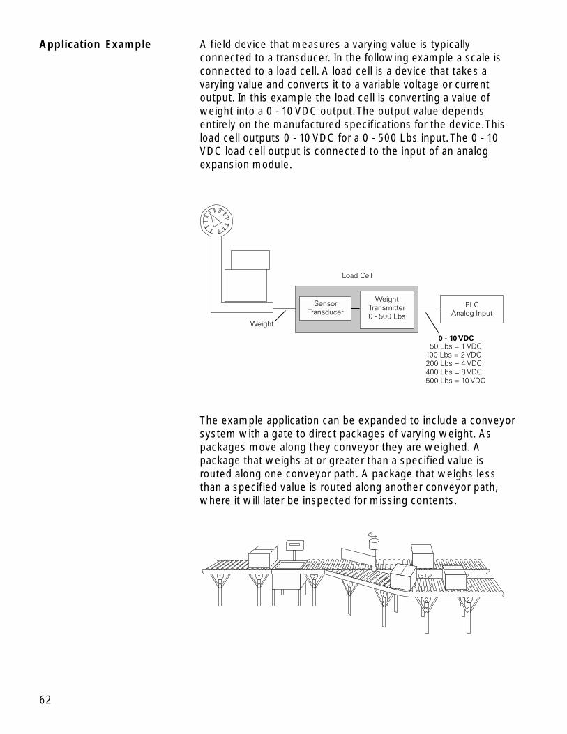
Application Example A field device that measures a varying value is typicallyconnected to a transducer. In the following example a scale isconnected to a load cell. A load cell is a device that takes avarying value and converts it to a variable voltage or currentoutput. In this example the load cell is converting a value ofweight into a 0 - 10 VDC output. The output value dependsentirely on the manufactured specifications for the device. Thisload cell outputs 0 - 10 VDC for a 0 - 500 Lbs input. The 0 - 10VDC load cell output is connected to the input of an analogexpansion module.
The example application can be expanded to include a conveyorsystem with a gate to direct packages of varying weight. Aspackages move along they conveyor they are weighed. Apackage that weighs at or greater than a specified value isrouted along one conveyor path. A package that weighs lessthan a specified value is routed along another conveyor path,where it will later be inspected for missing contents.

63
Analog Outputs Analog outputs are used in applications requiring controlcapability of field devices which respond to continuous voltageor current levels. Analog outputs may be used as a variablereference for control valves, chart recorders, electric motordrives, analog meters, and pressure transducers. Like analoginputs, analog outputs are generally connected to a controllingdevice through a transducer. The transducer takes the voltagesignal and, depending on the requirement, amplifies, reduces,or changes it into another signal which controls the device. Inthe following example a 0 - 10 VDC signal controls a 0 - 500 Lbs.scale analog meter.
64
Timers
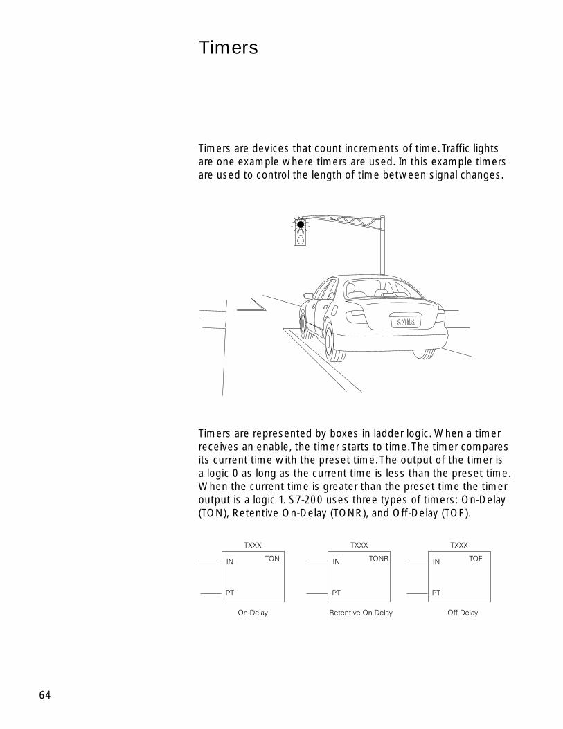
Timers are devices that count increments of time. Traffic lightsare one example where timers are used. In this example timersare used to control the length of time between signal changes.
Timers are represented by boxes in ladder logic. When a timerreceives an enable, the timer starts to time. The timer comparesits current time with the preset time. The output of the timer isa logic 0 as long as the current time is less than the preset time.When the current time is greater than the preset time the timeroutput is a logic 1. S7-200 uses three types of timers: On-Delay(TON), Retentive On-Delay (TONR), and Off-Delay (TOF).

65
S7-200 Timers S7-200 timers are provided with resolutions of 1 millisecond, 10milliseconds, and 100 milliseconds. The maximum value ofthese timers is 32.767 seconds, 327.67 seconds, and 3276.7seconds, respectively. By adding program elements, logic canbe programmed for much greater time intervals.
Hard-Wired Timing Circuit Timers used with PLCs can be compared to timing circuits usedin hard-wired control line diagrams. In the following example, anormally open (NO) switch (S1) is used with a timer (TR1). Forthis example the timer has been set for 5 seconds. When S1 isclosed, TR1 begins timing. When 5 seconds have elapsed, TR1will close its associated normally open TR1 contacts,illuminating pilot light PL1. When S1 is open, deenergizing TR1,the TR1 contacts open, immediately extinguishing PL1. This typeof timer is referred to as ON delay. ON delay indicates that oncea timer receives an enable signal, a predetermined amount oftime (set by the timer) must pass before the timer’s contactschange state.
On-Delay (TON) When the On-Delay timer (TON) receives an enable (logic 1) atits input (IN), a predetermined amount of time (preset time - PT)passes before the timer bit (T-bit) turns on. The T-bit is a logicfunction internal to the timer and is not shown on the symbol.The timer resets to the starting time when the enabling inputgoes to a logic 0.
66
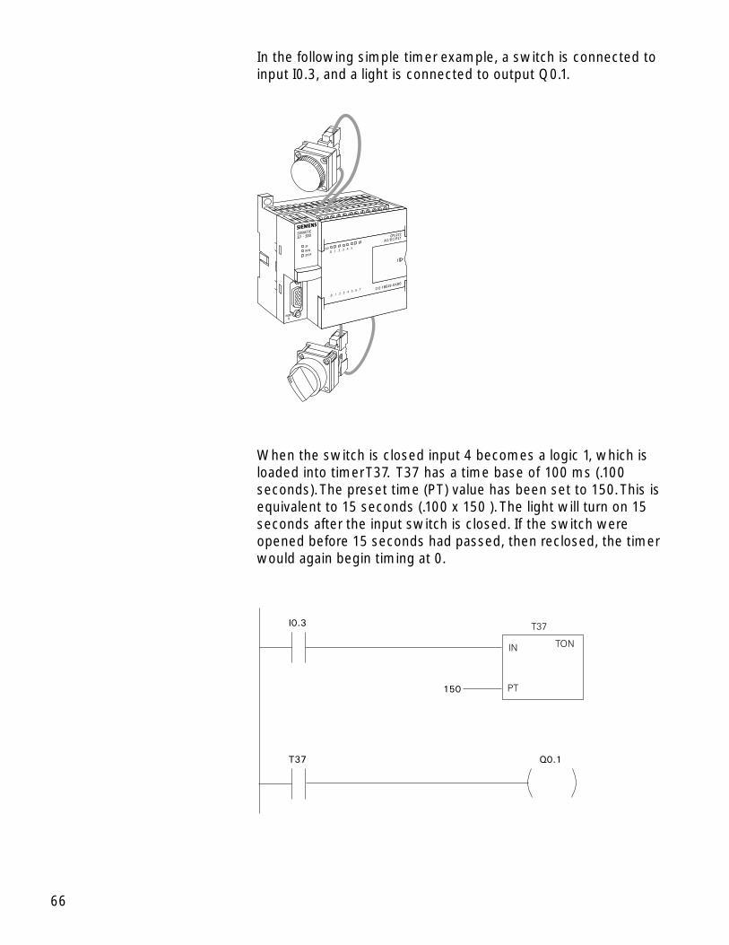
In the following simple timer example, a switch is connected toinput I0.3, and a light is connected to output Q0.1.
When the switch is closed input 4 becomes a logic 1, which isloaded into timer T37. T37 has a time base of 100 ms (.100seconds). The preset time (PT) value has been set to 150. This isequivalent to 15 seconds (.100 x 150 ). The light will turn on 15seconds after the input switch is closed. If the switch wereopened before 15 seconds had passed, then reclosed, the timerwould again begin timing at 0.
T37
150
I0.3
Q0.1
TON
T37
IN
PT
67
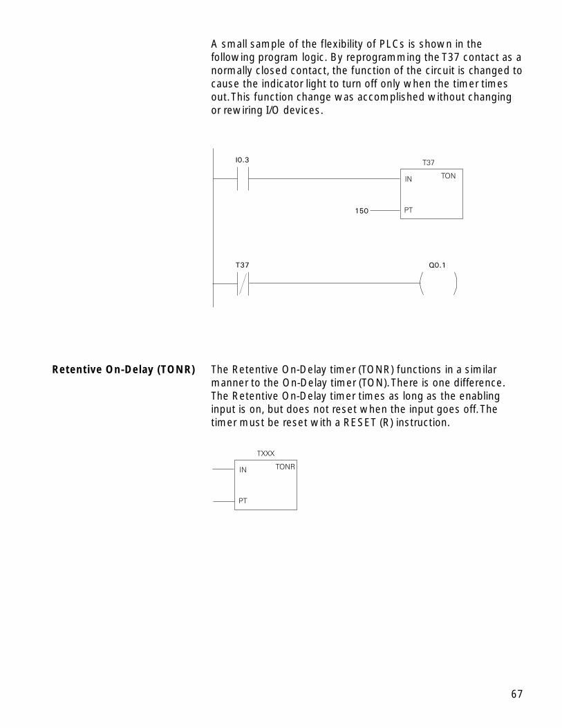
A small sample of the flexibility of PLCs is shown in thefollowing program logic. By reprogramming the T37 contact as anormally closed contact, the function of the circuit is changed tocause the indicator light to turn off only when the timer timesout. This function change was accomplished without changingor rewiring I/O devices.
T37
150
I0.3
Q0.1
TON
T37
IN
PT
Retentive On-Delay (TONR) The Retentive On-Delay timer (TONR) functions in a similarmanner to the On-Delay timer (TON). There is one difference.The Retentive On-Delay timer times as long as the enablinginput is on, but does not reset when the input goes off. Thetimer must be reset with a RESET (R) instruction.

68
The same example used with the On-Delay timer will be usedwith the Retentive On-Delay timer. When the switch is closed atinput I0.3, timer T5 (Retentive timer) begins timing. If, forexample, after 10 seconds input I0.3 is opened the timer stops.When input I0.3 is closed the timer will begin timing at 10seconds. The light will turn on 5 seconds after input I0.3 hasbeen closed the second time. A RESET (R) instruction can beadded. Here a pushbutton is connected to input I0.2. If after 10seconds input I0.3 were opened, T5 can be reset bymomentarily closing input I0.2. T5 will be reset to 0 and begintiming from 0 when input I0.3 is closed again.
T5
T5
150
I0.3
I0.2
Q0.1
R
TONR
T5
IN
PT
Off-Delay (TOF) The Off-Delay timer is used to delay an output off for a fixedperiod of time after the input turns off. When the enabling bitturns on the timer bit turns on immediately and the value is setto 0. When the input turns off, the timer counts until the presettime has elapsed before the timer bit turns off.
TOF
TXXX
IN
PT

69
S7-200 Timers The S7-200s have 256 timers. The specific T number chosen forthe timer determines its time base and whether it is TON,TONR, or TOF.
Timer Example In the following example a tank will be filled with twochemicals, mixed, and then drained. When the Start Button ispressed at input I0.0, the program starts pump 1 controlled byoutput Q0.0. Pump 1 runs for 5 seconds, filling the tank withthe first chemical, then shuts off. The program then starts pump2, controlled by output Q0.1. Pump 2 runs for 3 seconds fillingthe tank with the second chemical. After 3 seconds pump 2shuts off. The program starts the mixer motor, connected tooutput Q0.2 and mixes the two chemicals for 60 seconds. Theprogram then opens the drain valve controlled by output Q0.3,and starts pump 3 controlled by output Q0.4. Pump 3 shuts offafter 8 seconds and the process stops. A manual Stop switch isalso provided at input I0.1.
Timer Type Resolution Maximum Value Timer Number1 ms 32.767 seconds T0, T6410 ms 327.67 seconds T1-T4, T65-T68100 ms 3276.7 seconds T5-T31, T69-T951 ms 32.767 seconds T32, T9610 ms 327.67 seconds T33-T36, T97-T100100 ms 3276.7 seconds T37-T63, T101-T255
TONR
TON, TOF

70
Review 51. Analog signals are converted into a ____________
format by the PLC.
2. Three types of timers available in the S7-200 are On-Delay, ____________ On-Delay, and ____________-Delay.
3. The maximum time available on a 100 millisecond timebase timer is ____________ seconds.
4. A count of 25 on a 10 millisecond time base timerrepresents a time of __________ milliseconds.
5. There are ____________ timers in the S7-200.
71
Counters
Counters used in PLCs serve the same function as mechanicalcounters. Counters compare an accumulated value to a presetvalue to control circuit functions. Control applications thatcommonly use counters include the following:
• Count to a preset value and cause an event to occur
• Cause an event to occur until the count reaches a presetvalue
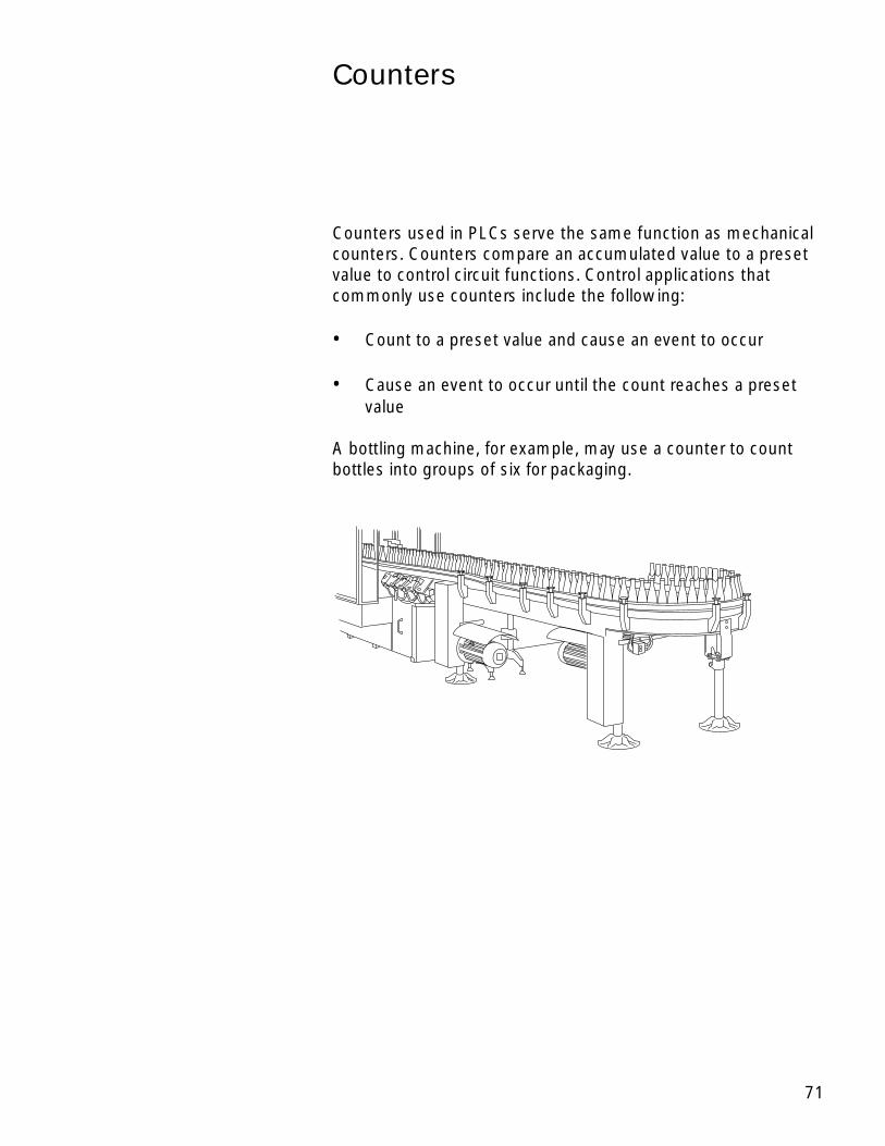
A bottling machine, for example, may use a counter to countbottles into groups of six for packaging.

72
Counters are represented by boxes in ladder logic. Countersincrement/decrement one count each time the input transitionsfrom off (logic 0) to on (logic 1). The counters are reset when aRESET instruction is executed. S7-200 uses three types ofcounters: up counter (CTU), down counter (CTD), and up/downcounter (CTUD).
Count Up/DownCount Up Count Down
PV PV
R LD
PV
CU CDCD
CU
R
CTU CTD CTUD
XXX XXX XXX
S7-200 Counters There are 256 counters in the S7-200, numbered C0 throughC255. The same number cannot be assigned to more than onecounter. For example, if an up counter is assigned number 45, adown counter cannot also be assigned number 45. Themaximum count value of a counter is ±32,767.
Up Counter The up counter counts up from a current value to a preset value(PV). Input CU is the count input. Each time CU transitions froma logic 0 to a logic 1 the counter increments by a count of 1.Input R is the reset. A preset count value is stored in PV input. Ifthe current count is equal to or greater than the preset valuestored in PV, the output bit (Q) turns on (not shown).
PV
R
CU
CTU
XXX

73
Down Counter The down counter counts down from the preset value (PV) eachtime CD transitions from a logic 0 to a logic 1. When the currentvalue is equal to zero the counter output bit (Q) turns on (notshown). The counter resets and loads the current value with thepreset value (PV) when the load input (LD) is enabled.
PV
LD
CD
CTD
XXX
Up/Down Counter The up/down counter counts up or down from the preset valueeach time either CD or CU transitions from a logic 0 to a logic 1.When the current value is equal to the preset value, the outputQU turns on. When the current value (CV) is equal to zero, theoutput QD turns on. The counter loads the current value (CV)with the preset value (PV) when the load input (LD) is enabled.Similarly, the counter resets and loads the current value (CV)with zero when the reset (R) is enabled. The counter stopscounting when it reaches preset or zero.
PV
LD
CD
CU
R
CTUD
XXX
Counter Example A counter might be used to keep track of the number ofvehicles in a parking lot. As vehicles enter the lot through anentrance gate, the counter counts up. As vehicles exit the lotthrough an exit gate, the counter counts down. When the lot isfull a sign at the entrance gate turns on indicating the lot is full.
74
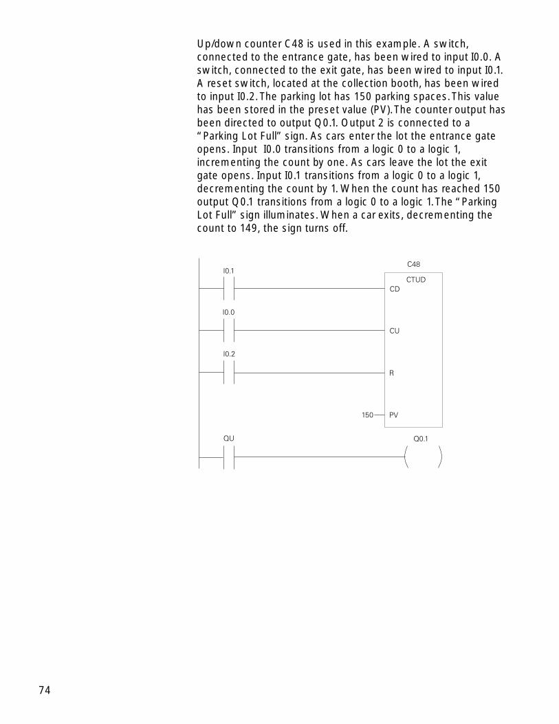
Up/down counter C48 is used in this example. A switch,connected to the entrance gate, has been wired to input I0.0. Aswitch, connected to the exit gate, has been wired to input I0.1.A reset switch, located at the collection booth, has been wiredto input I0.2. The parking lot has 150 parking spaces. This valuehas been stored in the preset value (PV). The counter output hasbeen directed to output Q0.1. Output 2 is connected to a“Parking Lot Full” sign. As cars enter the lot the entrance gateopens. Input I0.0 transitions from a logic 0 to a logic 1,incrementing the count by one. As cars leave the lot the exitgate opens. Input I0.1 transitions from a logic 0 to a logic 1,decrementing the count by 1. When the count has reached 150output Q0.1 transitions from a logic 0 to a logic 1. The “ParkingLot Full” sign illuminates. When a car exits, decrementing thecount to 149, the sign turns off.

75
High-Speed Instructions
As discussed earlier, PLCs have a scan time. The scan timedepends on the size of the program, the number of I/Os, andthe amount of communication required. Events may occur in anapplication that require a response from the PLC before thescan cycle is complete. For these applications high-speedinstructions can be used.
High-Speed Counters High-speed counters are represented by boxes in ladder logic.The S7-221 and S7-222 supports four high-speed counters(HSC0, HSC3, HSC4, HSC5). The CPU 224 and CPU 226supports six high-speed counters (HSC0, HSC1, HSC2, HSC3,HSC4, HSC5).
76
Definition Boxes and The high-speed counter definition boxes are used to assignHigh-Speed Counters a mode to the counter. High-speed counters can be defined by
the definition box to operate in any of the twelve availablemodes. It should be noted that not all counters can operate in allof the available modes. Refer to the S7-ProgrammableController System Manual for definitions available for eachcounter. Each counter has dedicated inputs for clocks, directioncontrol, reset, and start where these functions are supported.The maximum clock input frequency is 20 kHz. For the two-phase counters, both clocks may be run at 20 kHz. In quadraturemode, 1x or 4x counting rates can be selected. At 1x rate themaximum counting frequency is 20 kHz. At 4x rate themaximum counting frequency is 80 kHz.
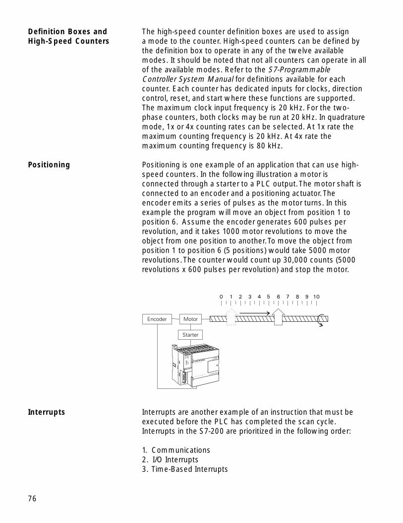
Positioning Positioning is one example of an application that can use high-speed counters. In the following illustration a motor isconnected through a starter to a PLC output. The motor shaft isconnected to an encoder and a positioning actuator. Theencoder emits a series of pulses as the motor turns. In thisexample the program will move an object from position 1 toposition 6. Assume the encoder generates 600 pulses perrevolution, and it takes 1000 motor revolutions to move theobject from one position to another. To move the object fromposition 1 to position 6 (5 positions) would take 5000 motorrevolutions. The counter would count up 30,000 counts (5000revolutions x 600 pulses per revolution) and stop the motor.
Interrupts Interrupts are another example of an instruction that must beexecuted before the PLC has completed the scan cycle.Interrupts in the S7-200 are prioritized in the following order:
1. Communications2. I/O Interrupts3. Time-Based Interrupts
77
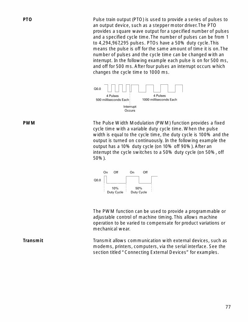
PTO Pulse train output (PTO) is used to provide a series of pulses toan output device, such as a stepper motor driver. The PTOprovides a square wave output for a specified number of pulsesand a specified cycle time. The number of pulses can be from 1to 4,294,967,295 pulses. PTOs have a 50% duty cycle. Thismeans the pulse is off for the same amount of time it is on. Thenumber of pulses and the cycle time can be changed with aninterrupt. In the following example each pulse is on for 500 ms,and off for 500 ms. After four pulses an interrupt occurs whichchanges the cycle time to 1000 ms.
Q0.0
4 Pulses500 milliseconds Each
4 Pulses1000 milliseconds Each
InterruptOccurs
PWM The Pulse Width Modulation (PWM) function provides a fixedcycle time with a variable duty cycle time. When the pulsewidth is equal to the cycle time, the duty cycle is 100% and theoutput is turned on continuously. In the following example theoutput has a 10% duty cycle (on 10% off 90%). After aninterrupt the cycle switches to a 50% duty cycle (on 50%, off50%).
Q0.0
On OnOff Off
10%Duty Cycle
50%Duty Cycle
The PWM function can be used to provide a programmable oradjustable control of machine timing. This allows machineoperation to be varied to compensate for product variations ormechanical wear.
Transmit Transmit allows communication with external devices, such asmodems, printers, computers, via the serial interface. See thesection titled “Connecting External Devices” for examples.

78
Network Communications
Information flow between intelligent devices such as PLCs,computers, variable speed drives, actuators, and sensors isoften accomplished through a local area network (LAN). LANsare used in office, manufacturing, and industrial areas.
In the past, these networks were often proprietary systemsdesigned to a specific vendor’s standards. Siemens has been aleader in pushing the trend to open systems based uponinternational standards developed through industryassociations. PROFIBUS-DP and Actuator Sensor Interface(AS-i) are examples of these open networks.
The PROFIBUS-DP EM 277 module allows connection ofthe S7-200 CPU to a PROFIBUS-DP network as a slave. TheCP 243-2 Communication Processor allows communicationbetween AS-i devices and an S7-200.
79
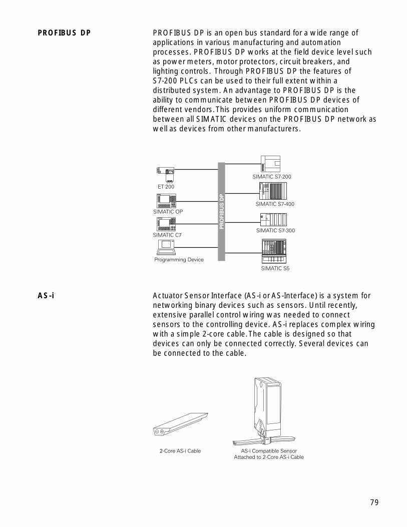
PROFIBUS DP PROFIBUS DP is an open bus standard for a wide range ofapplications in various manufacturing and automationprocesses. PROFIBUS DP works at the field device level suchas power meters, motor protectors, circuit breakers, andlighting controls. Through PROFIBUS DP the features ofS7-200 PLCs can be used to their full extent within adistributed system. An advantage to PROFIBUS DP is theability to communicate between PROFIBUS DP devices ofdifferent vendors. This provides uniform communicationbetween all SIMATIC devices on the PROFIBUS DP network aswell as devices from other manufacturers.
AS-i Actuator Sensor Interface (AS-i or AS-Interface) is a system fornetworking binary devices such as sensors. Until recently,extensive parallel control wiring was needed to connectsensors to the controlling device. AS-i replaces complex wiringwith a simple 2-core cable. The cable is designed so thatdevices can only be connected correctly. Several devices canbe connected to the cable.

80
PLCs, for example, use I/O modules to receive inputs frombinary devices such as sensors. Binary outputs are used to turnon or off a process as the result of an input.
Web Site For more information and sales support on the S7-200 visit ourweb site at http://www.siemens.com/s7-200.
Review 61. The S7-200 supports ____________ counters.
2. Three types of counters used in S7-200 are____________ , ____________ , and ____________ .
3. Counters can count to a maximum of ____________ .
4. Events that require an action from the PLC before thescan cycle is complete are controlled by ________________________ instructions.
5. Depending on the counter, there are up to ____________modes available on high-speed counters.
6. The ____________ allows communication between AS-idevices and an S7-200.
81
Review Answers
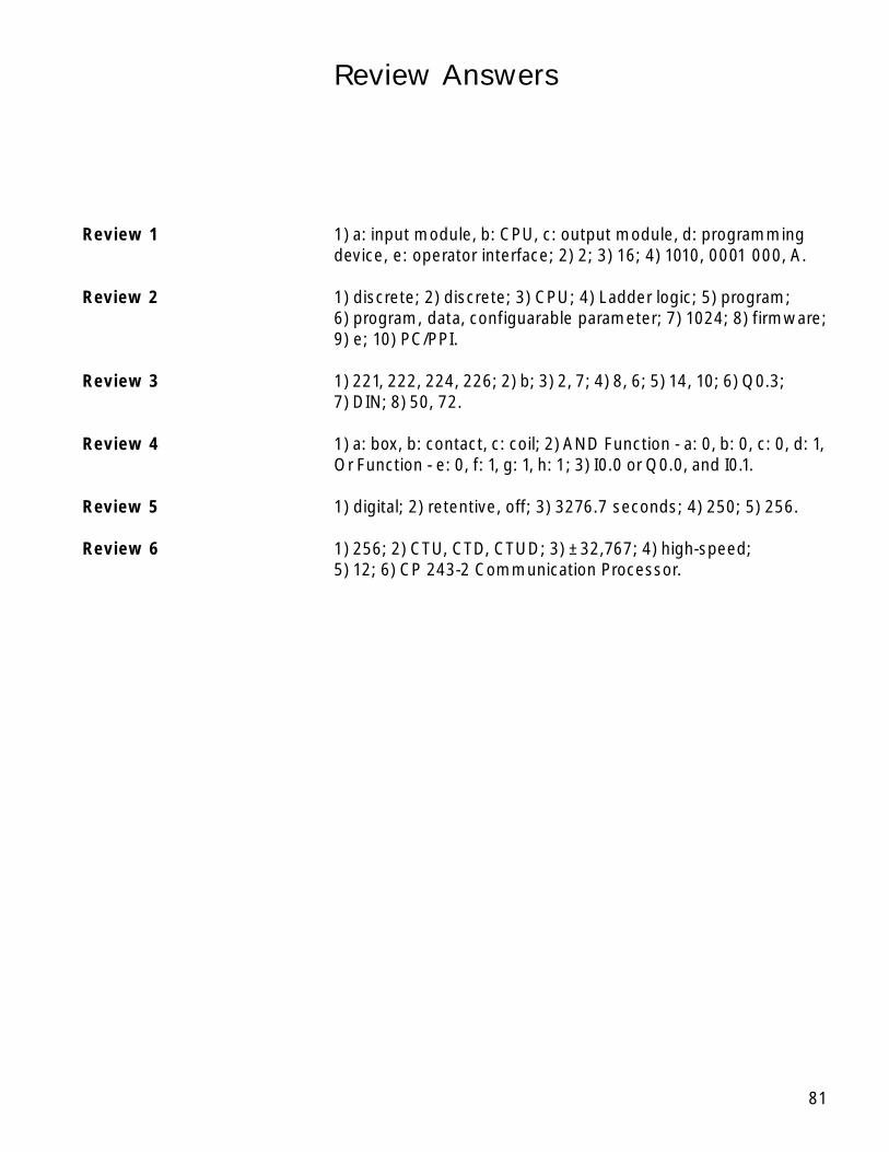
Review 1 1) a: input module, b: CPU, c: output module, d: programmingdevice, e: operator interface; 2) 2; 3) 16; 4) 1010, 0001 000, A.
Review 2 1) discrete; 2) discrete; 3) CPU; 4) Ladder logic; 5) program;6) program, data, configuarable parameter; 7) 1024; 8) firmware;9) e; 10) PC/PPI.
Review 3 1) 221, 222, 224, 226; 2) b; 3) 2, 7; 4) 8, 6; 5) 14, 10; 6) Q0.3;7) DIN; 8) 50, 72.
Review 4 1) a: box, b: contact, c: coil; 2) AND Function - a: 0, b: 0, c: 0, d: 1,Or Function - e: 0, f: 1, g: 1, h: 1; 3) I0.0 or Q0.0, and I0.1.
Review 5 1) digital; 2) retentive, off; 3) 3276.7 seconds; 4) 250; 5) 256.
Review 6 1) 256; 2) CTU, CTD, CTUD; 3) ±32,767; 4) high-speed;5) 12; 6) CP 243-2 Communication Processor.

82
Final Exam
The final exam is intended to be a learning tool. The book maybe used during the exam. A tear-out answer sheet is provided.After completing the test, mail the answer sheet in for grading.A grade of 70% or better is passing. Upon successfulcompletion of the test a certificate will be issued.
1. The component of a PLC that makes decisions andexecutes control instructions based on the input signals isthe ____________ .
a. CPU b. Input modulec. Programming device d. Operator interface
2. One byte is made up of ____________ .
a. 2 bits b. 8 bitsc. 16 bits d. 32 bits
3. The binary equivalent of a decimal 5 is ____________ .
a. 11 b. 100c. 101 d. 111
4. An input that is either On or Off is a/an ____________ input.
a. analog b. discretec. high-speed d. normally open
5. A programming language that uses symbols resemblingelements used in hard-wired control line diagrams isreferred to as a ____________ .
a. ladder logic diagram b. statement listc. network d. PLC scan
Questions
83
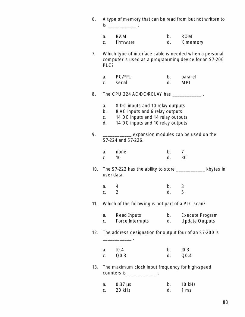
6. A type of memory that can be read from but not written tois ____________ .
a. RAM b. ROMc. firmware d. K memory
7. Which type of interface cable is needed when a personalcomputer is used as a programming device for an S7-200PLC?
a. PC/PPI b. parallelc. serial d. MPI
8. The CPU 224 AC/DC/RELAY has ____________ .
a. 8 DC inputs and 10 relay outputsb. 8 AC inputs and 6 relay outputsc. 14 DC inputs and 14 relay outputsd. 14 DC inputs and 10 relay outputs
9. ____________ expansion modules can be used on theS7-224 and S7-226.
a. none b. 7c. 10 d. 30
10. The S7-222 has the ability to store ____________ kbytes inuser data.
a. 4 b. 8c. 2 d. 5
11. Which of the following is not part of a PLC scan?
a. Read Inputs b. Execute Programc. Force Interrupts d. Update Outputs
12. The address designation for output four of an S7-200 is____________ .
a. I0.4 b. I0.3c. Q0.3 d. Q0.4
13. The maximum clock input frequency for high-speedcounters is ____________ .
a. 0.37 µs b. 10 kHzc. 20 kHz d. 1 ms

84
14. The maximum value of an S7-200 timer with a resolution of1 millisecond is ____________ seconds.
a. 3.2767 b. 32.767c. 327.67 d. 3276.7
15. An S7-200 timer with a time base of 100 ms can count to amaximum value of ____________ seconds.
a. 3.2767 b. 32.767c. 327.67 d. 3276.7
16. The time base of TON 32 of is ____________ ms.
a. .1 b. 10c. 1 d. 100
17. The maximum count of an S7-200 up counter is____________ .
a. 32,767 b. 65,534c. 98,301 d. 1,000,000
18. A/An ____________ is used to assign a mode to a high-speed counter.
a. toggle switch b. interruptc. PLC scan d. definition box
19. ____________ instructions allows communication withexternal devices, such as modems, printers, andcomputers.
a. Transmit b. Interruptc. High-speed counters d. High-speed outputs
20. ____________ is used to temporarily override the input oroutput status in order to test and debug the program.
a. Transmit b. Forcingc. Interrupt d. PLC scan