a+ guide to hardware: managing, maintaining, and troubleshooting, 5e chapter 6 supporting hard...
TRANSCRIPT
A+ Guide to Hardware: Managing, Maintaining, and
Troubleshooting, 5e
Chapter 6Supporting Hard Drives
A+ Guide to Hardware modified by Dr. Feda AlShahwan 2
Objectives
• Learn about the technologies used inside a hard drive and how data is organized on the drive
• Learn how a computer communicates with a hard drive
• Learn how hard drives can work together in a RAID array
• Learn about floppy drives
• Learn how to select and install a hard drive
• Learn how to solve hard drive problems
A+ Guide to Hardware modified by Dr. Feda AlShahwan 3
Inside a Hard Drive
• The hard disk drive is a nonvolatile secondary storage unit. That means that it does not loose its stored data when turned off.
• Installed inside a drive bay and there is no access to the HDD from the front panel as it is unnecessary.
A+ Guide to Hardware modified by Dr. Feda AlShahwan 4
Inside a Hard Drive• Hard drives are different in :
– Hardware technologies inside the drive• Solid state or magnetic or hybrid
– Data organization inside a hard drive
– Hard disk drive (HDD) or hard drive sizes• 2.5" size for laptop computers• 3.5" size for desktops• 1.8" size for low-end laptops, other equipment
– Encoding method that determines how data is written to and read from the hard disk drive.• MFM (Modified Frequency Modulation)• RLL (Run Length Limited)
– Interface type
A+ Guide to Hardware modified by Dr. Feda AlShahwan 5
Solid State, Magnetic, and Hybrid Drives
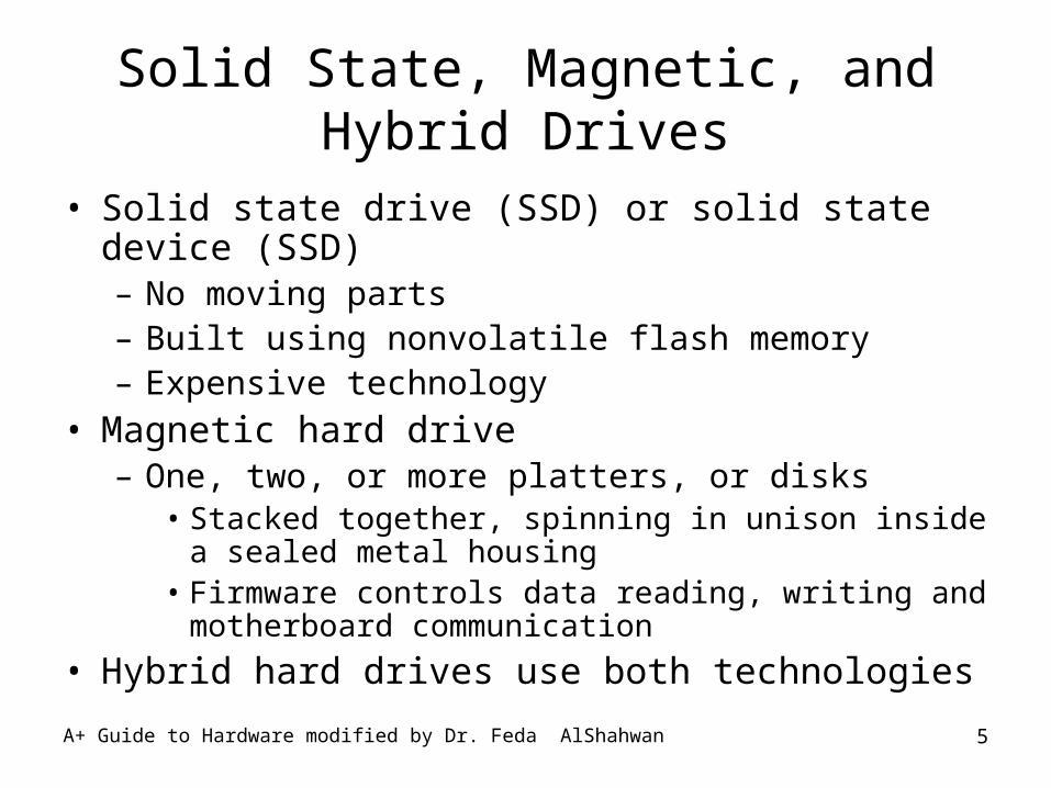
• Solid state drive (SSD) or solid state device (SSD)– No moving parts– Built using nonvolatile flash memory– Expensive technology
• Magnetic hard drive– One, two, or more platters, or disks
• Stacked together, spinning in unison inside a sealed metal housing
• Firmware controls data reading, writing and motherboard communication
• Hybrid hard drives use both technologies
A+ Guide to Hardware modified by Dr. Feda AlShahwan 6
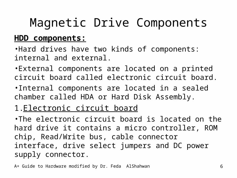
Magnetic Drive ComponentsHDD components:•Hard drives have two kinds of components: internal and external. •External components are located on a printed circuit board called electronic circuit board.•Internal components are located in a sealed chamber called HDA or Hard Disk Assembly.
1.Electronic circuit board•The electronic circuit board is located on the hard drive it contains a micro controller, ROM chip, Read/Write bus, cable connector interface, drive select jumpers and DC power supply connector.
A+ Guide to Hardware modified by Dr. Feda AlShahwan 7
Magnetic Drive Components
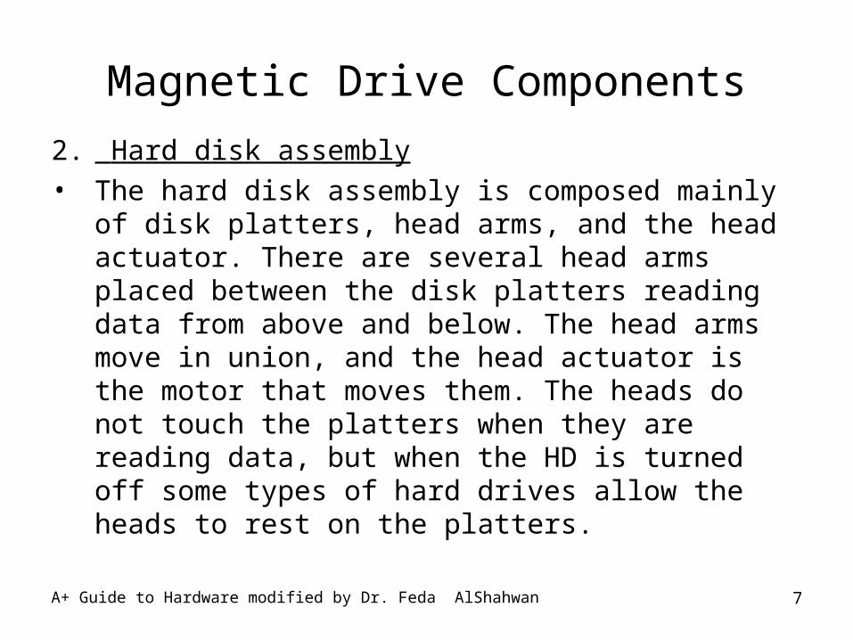
2. Hard disk assembly
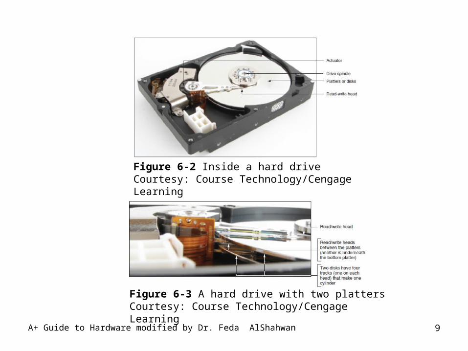
• The hard disk assembly is composed mainly of disk platters, head arms, and the head actuator. There are several head arms placed between the disk platters reading data from above and below. The head arms move in union, and the head actuator is the motor that moves them. The heads do not touch the platters when they are reading data, but when the HD is turned off some types of hard drives allow the heads to rest on the platters.
A+ Guide to Hardware modified by Dr. Feda AlShahwan 8
A+ Guide to Hardware modified by Dr. Feda AlShahwan 9
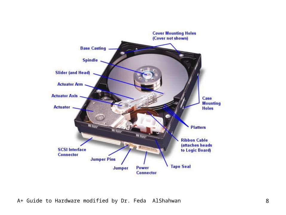
Figure 6-2 Inside a hard driveCourtesy: Course Technology/Cengage Learning
Figure 6-3 A hard drive with two plattersCourtesy: Course Technology/Cengage Learning
A+ Guide to Hardware modified by Dr. Feda AlShahwan 10
How Data Is Organized On a Hard Drive
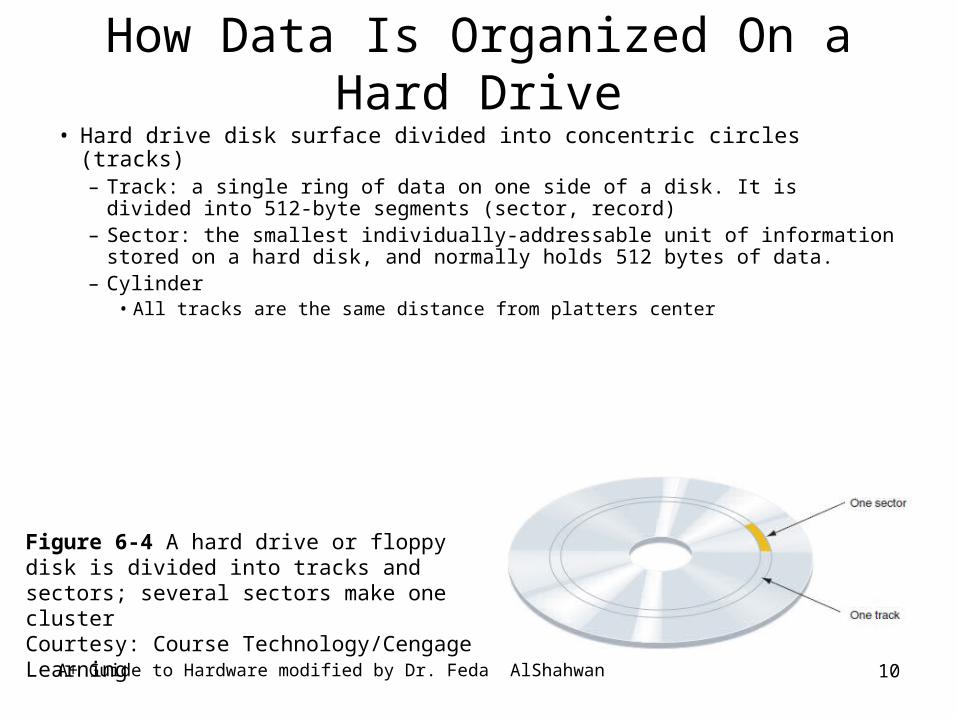
• Hard drive disk surface divided into concentric circles (tracks)– Track: a single ring of data on one side of a disk. It is divided into
512-byte segments (sector, record)– Sector: the smallest individually-addressable unit of information
stored on a hard disk, and normally holds 512 bytes of data.– Cylinder
• All tracks are the same distance from platters center
Figure 6-4 A hard drive or floppy disk is divided into tracks and sectors; several sectors make one clusterCourtesy: Course Technology/Cengage Learning
A+ Guide to Hardware modified by Dr. Feda AlShahwan 11
How Data Is Organized On a Hard Drive (cont’d.)
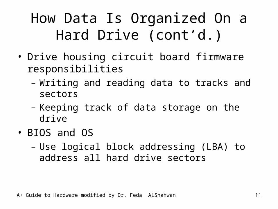
• Drive housing circuit board firmware responsibilities– Writing and reading data to tracks and sectors– Keeping track of data storage on the drive
• BIOS and OS– Use logical block addressing (LBA) to address all
hard drive sectors
A+ Guide to Hardware modified by Dr. Feda AlShahwan 12
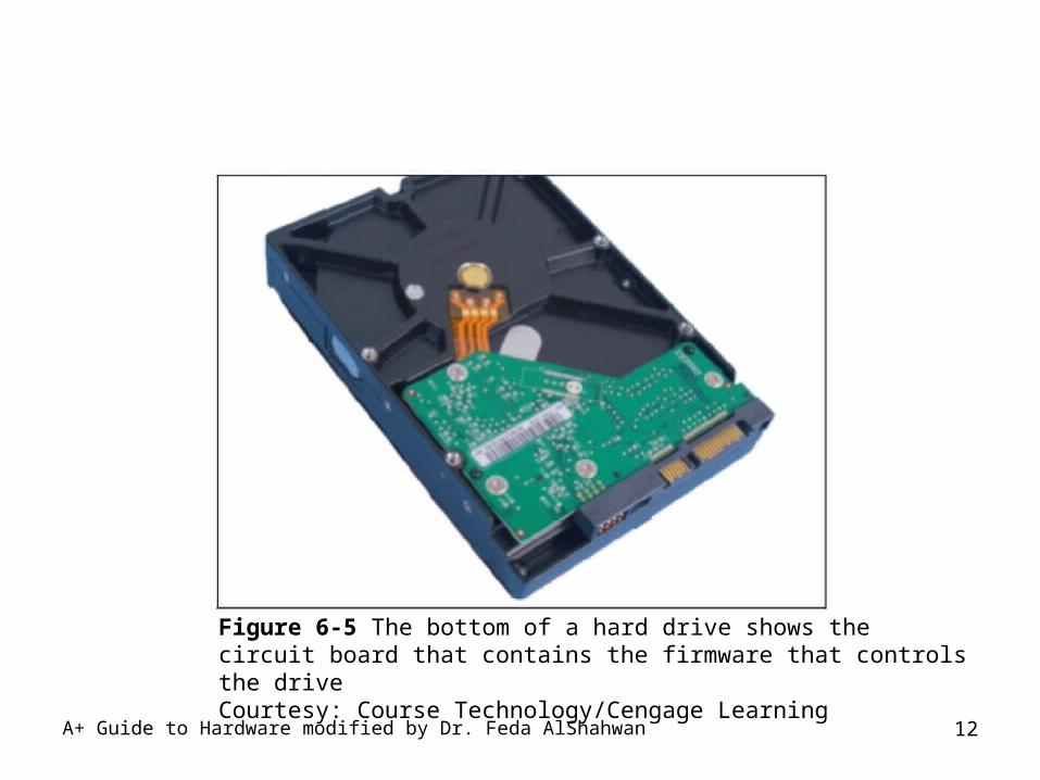
Figure 6-5 The bottom of a hard drive shows the circuit board that contains the firmware that controls the driveCourtesy: Course Technology/Cengage Learning
A+ Guide to Hardware modified by Dr. Feda AlShahwan 13
How Data Is Organized On a Hard Drive (cont’d.)
• Hard drive installation– Windows initializes and identifies drive as a basic disk
• Writes Master Boot Record (MBR)– High-level formatting performed
• Specifies partition size and file system used– Partition can be primary or extended
• Extended can be divided into one or more logical drives– File system
• Overall structure OS uses to name, store, organize files on a drive
A+ Guide to Hardware modified by Dr. Feda AlShahwan 14
How Data Is Organized On a Hard Drive (cont’d.)
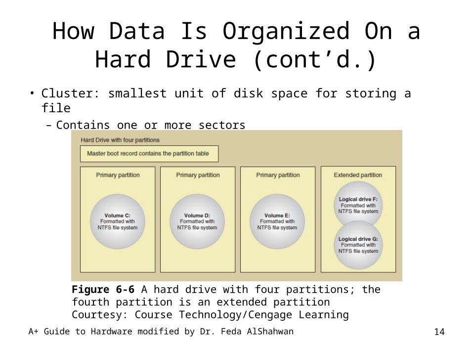
• Cluster: smallest unit of disk space for storing a file– Contains one or more sectors
Figure 6-6 A hard drive with four partitions; the fourth partition is an extended partitionCourtesy: Course Technology/Cengage Learning
A+ Guide to Hardware modified by Dr. Feda AlShahwan 15
How Data Is Organized On a Hard Drive (cont’d.)
• Primary and extended partition creation– When drive or OS is first installed– After existing partition becomes corrupted
• Disk Management tool
• File system choices– Windows XP
• FAT32, NTFS• exFAT if Service Packs 2 & 3 installed with download
– Windows Vista with Service Pack 1 or later• FAT32, NTFS, exFAT
A+ Guide to Hardware modified by Dr. Feda AlShahwan 16
Hard Drive Interface Standards
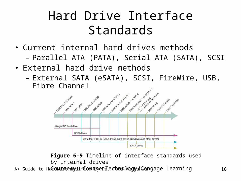
• Current internal hard drives methods– Parallel ATA (PATA), Serial ATA (SATA), SCSI
• External hard drive methods– External SATA (eSATA), SCSI, FireWire, USB, Fibre
Channel
Figure 6-9 Timeline of interface standards used by internal drivesCourtesy: Course Technology/Cengage Learning
A+ Guide to Hardware modified by Dr. Feda AlShahwan 17
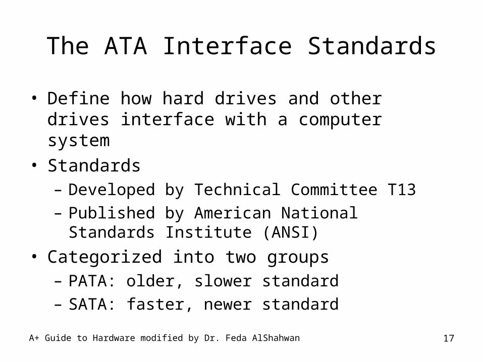
The ATA Interface Standards
• Define how hard drives and other drives interface with a computer system
• Standards– Developed by Technical Committee T13– Published by American National Standards Institute
(ANSI)
• Categorized into two groups– PATA: older, slower standard– SATA: faster, newer standard
A+ Guide to Hardware modified by Dr. Feda AlShahwan 18
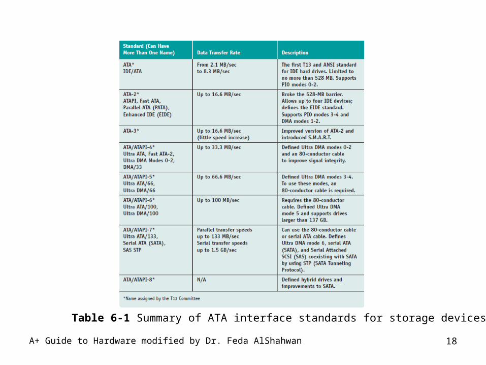
Table 6-1 Summary of ATA interface standards for storage devices
A+ Guide to Hardware modified by Dr. Feda AlShahwan 19
The ATA Interface Standards (cont’d.)
• Parallel ATA or EIDE drive standards or Integrated Drive Electronics (IDE)– Allows one or two IDE connectors on a motherboard
• Each use 40-pin data cable– Advanced Technology Attachment Packet Interface
• Required by EIDE drives (e.g., CD or DVD)
• Types of PATA ribbon cables– Older cable
• 40 pins and 40 wires– 80-conductor IDE cable
• 40 pins and 80 wires– Maximum recommended length of either is 18 inches
A+ Guide to Hardware modified by Dr. Feda AlShahwan 20
The ATA Interface Standards (cont’d.)
• Transferring data between hard drive and memory– Direct memory access (DMA)
• Transfers data directly from drive to memory without involving the CPU
• Seven DMA modes– Programmed Input/Output (PIO) mode
• Involves the CPU, slower than DMA mode• Five PIO modes used by hard drives
– Ultra DMA• Data transferred twice for each clock beat, at the
beginning and again at the end
A+ Guide to Hardware modified by Dr. Feda AlShahwan 21
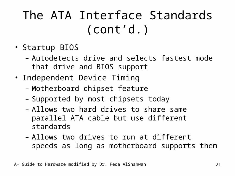
The ATA Interface Standards (cont’d.)
• Startup BIOS – Autodetects drive and selects fastest mode that drive
and BIOS support
• Independent Device Timing– Motherboard chipset feature– Supported by most chipsets today– Allows two hard drives to share same parallel ATA
cable but use different standards– Allows two drives to run at different speeds as long as
motherboard supports them
A+ Guide to Hardware modified by Dr. Feda AlShahwan 22
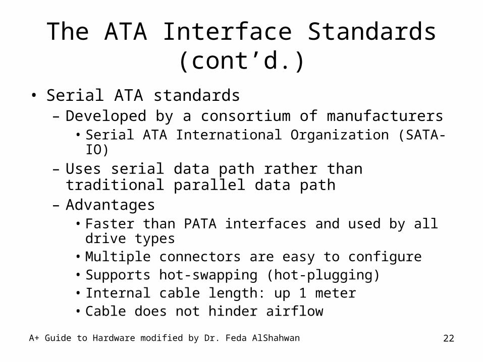
The ATA Interface Standards (cont’d.)
• Serial ATA standards– Developed by a consortium of manufacturers
• Serial ATA International Organization (SATA-IO)– Uses serial data path rather than traditional parallel
data path– Advantages
• Faster than PATA interfaces and used by all drive types• Multiple connectors are easy to configure• Supports hot-swapping (hot-plugging)• Internal cable length: up 1 meter• Cable does not hinder airflow
A+ Guide to Hardware modified by Dr. Feda AlShahwan 23
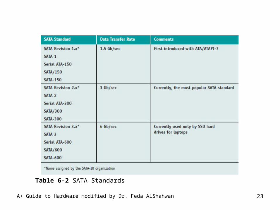
Table 6-2 SATA Standards
A+ Guide to Hardware modified by Dr. Feda AlShahwan 24
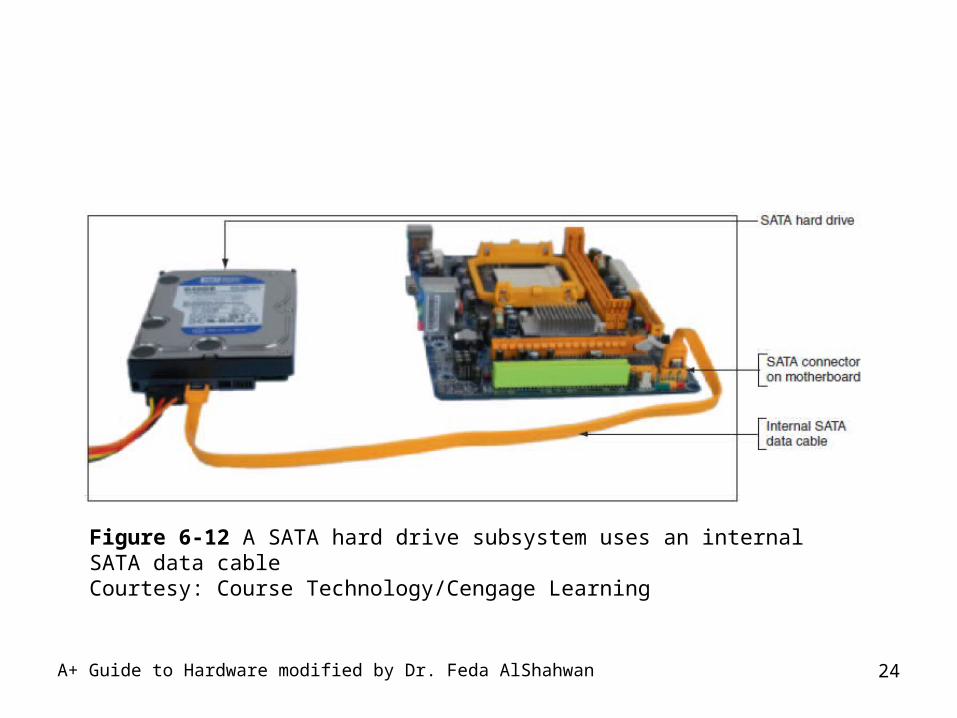
Figure 6-12 A SATA hard drive subsystem uses an internal SATA data cableCourtesy: Course Technology/Cengage Learning
A+ Guide to Hardware modified by Dr. Feda AlShahwan 25
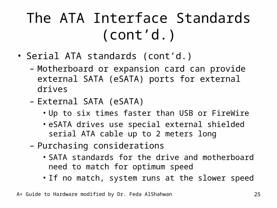
The ATA Interface Standards (cont’d.)
• Serial ATA standards (cont’d.)– Motherboard or expansion card can provide external
SATA (eSATA) ports for external drives– External SATA (eSATA)
• Up to six times faster than USB or FireWire
• eSATA drives use special external shielded serial ATA cable up to 2 meters long
– Purchasing considerations• SATA standards for the drive and motherboard need to
match for optimum speed
• If no match, system runs at the slower speed
A+ Guide to Hardware modified by Dr. Feda AlShahwan 26
SCSI Technology
• Small Computer System Interface standards – System bus to peripheral device communication– Support either 7 or 15 devices (standard dependent) – Provides better performance than ATA standards
• SCSI subsystem– SCSI controller types: embedded or host adapter– Host adapter supports internal and external devices– Daisy chain: combination of host adapter and devices– Each device on bus assigned SCSI ID (0 - 15)– A physical device can embed multiple logical devices
A+ Guide to Hardware modified by Dr. Feda AlShahwan 27
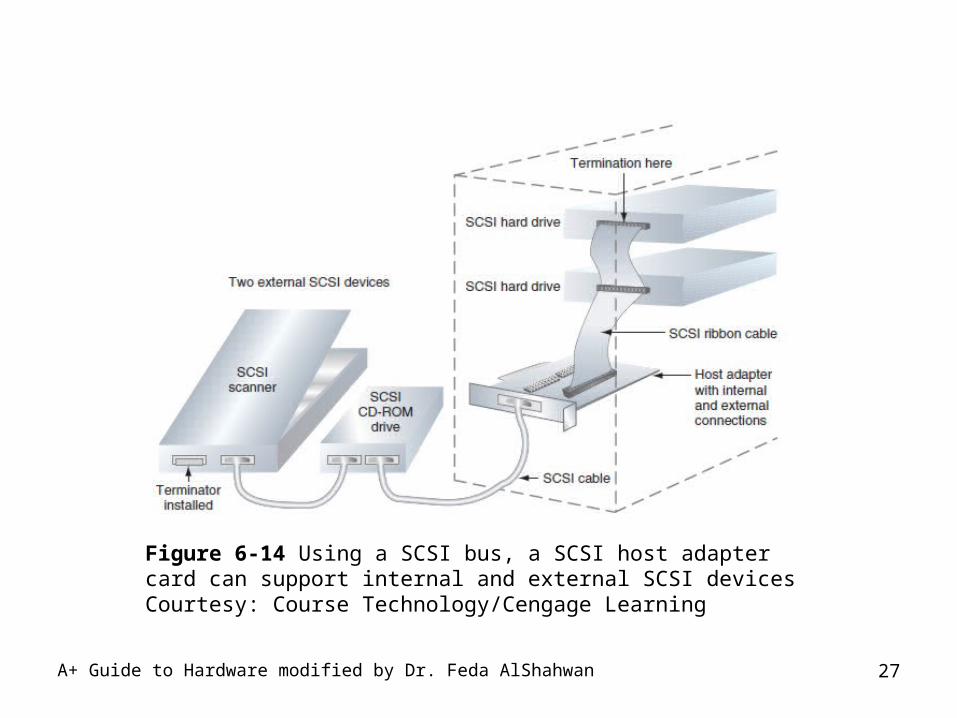
Figure 6-14 Using a SCSI bus, a SCSI host adapter card can support internal and external SCSI devicesCourtesy: Course Technology/Cengage Learning
A+ Guide to Hardware modified by Dr. Feda AlShahwan 28
SCSI Technology (cont’d.)
• Terminating resistor– Plugged into last device at end of the chain– Reduces electrical noise or interference on the cable
• Various SCSI standards– SCSI-1, SCSI-2, and SCSI-3
• Also known as regular SCSI, Fast SCSI, Ultra SCSI– Serial attached SCSI (SAS)
• Allows for more than 15 devices on single chain• Uses smaller, longer, round cables• Uses smaller hard drive form factors, larger capacities• Compatible with serial ATA
A+ Guide to Hardware modified by Dr. Feda AlShahwan 29
SCSI Technology (cont’d.)
• Fibre channel SCSI technology
• Advantages– Connects up to 126 devices on a single Fibre
Channel bus– Faster than other SCSI implementations when more
than five hard drives strung together
• Disadvantage– Expensive and has too much overhead
• Except when used in high-end server solutions
A+ Guide to Hardware modified by Dr. Feda AlShahwan 30
RAID: Hard Drives Working Together
• Two or more hard drives work together as an array of drives– Improves fault tolerance– Improves performance
• Most common RAID levels– RAID 0, RAID 1, RAID 5
• Spanning or JBOD (Just a Bunch of Disks)– Two hard drives configured as a single volume
• RAID is accomplished using hardware or software
A+ Guide to Hardware modified by Dr. Feda AlShahwan 31
About Floppy Drives
• Floppy disk drive (FDD)– Holds only 1.44 MB of data– Some still used today– Advantages
• Useful when recovering from a failed BIOS update
• Inexpensive and easy for transferring small amounts of data
A+ Guide to Hardware modified by Dr. Feda AlShahwan 32
Floppy Drive Hardware
• Past floppy drives sizes: 5 ¼” and 3 ½” – 3 ½” floppy disk format
• High density (1.44 MB), extra-high density (2.88 MB), double density (720 K)
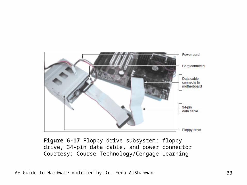
– Floppy drive subsystem• Floppy drive, ribbon cable, power cable, connections
• Today’s floppy drive cables have a connector at each end to accommodate a single drive
• Older cables have an extra connector or two in the middle of the cable for a second floppy drive
A+ Guide to Hardware modified by Dr. Feda AlShahwan 33
Figure 6-17 Floppy drive subsystem: floppy drive, 34-pin data cable, and power connectorCourtesy: Course Technology/Cengage Learning
A+ Guide to Hardware modified by Dr. Feda AlShahwan 34
Floppy Drive File System
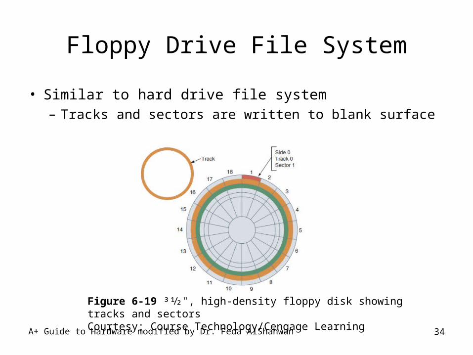
• Similar to hard drive file system– Tracks and sectors are written to blank surface
Figure 6-19 31⁄2", high-density floppy disk showing tracks and sectorsCourtesy: Course Technology/Cengage Learning
A+ Guide to Hardware modified by Dr. Feda AlShahwan 35
Floppy Drive File System (cont’d.)
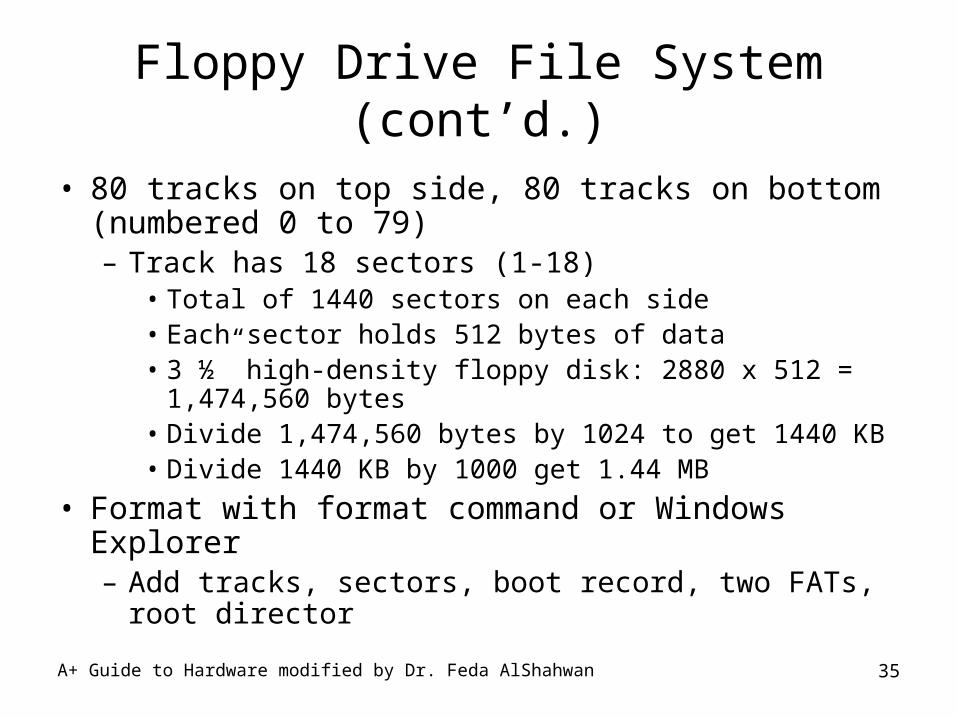
• 80 tracks on top side, 80 tracks on bottom (numbered 0 to 79)– Track has 18 sectors (1-18)
• Total of 1440 sectors on each side• Each sector holds 512 bytes of data• 3 ½” high-density floppy disk: 2880 x 512 = 1,474,560
bytes• Divide 1,474,560 bytes by 1024 to get 1440 KB• Divide 1440 KB by 1000 get 1.44 MB
• Format with format command or Windows Explorer – Add tracks, sectors, boot record, two FATs, root
director
A+ Guide to Hardware modified by Dr. Feda AlShahwan 36
How to Select and Install Hard Drives and Floppy Drives
• Topics covered– Selecting a hard drive– Installation details for serial ATA drive, parallel ATA
drive– How to install hard drive in a bay too wide for drive– How to set up a RAID system– How to install a floppy drive
A+ Guide to Hardware modified by Dr. Feda AlShahwan 37
Selecting a Hard Drive
• Hard drive must match OS and motherboard
• BIOS uses autodetection to prepare the device – Drive capacity and configuration selected– Best possible ATA standard becomes part of
configuration
• Selected device may not be supported by BIOS – Troubleshooting tasks (if device not recognized)
• Flash the BIOS
• Replace controller card
• Replace motherboard
A+ Guide to Hardware modified by Dr. Feda AlShahwan 38
Selecting a Hard Drive (cont’d.)
• Considerations:– Drive capacity– Spindle speed– Interface standard– Cache or buffer size– Average seek time (time to fetch data)– Hybrid drive– Manufacturer warranty (keep receipt)– Price range
A+ Guide to Hardware modified by Dr. Feda AlShahwan 39
Steps to Install a Serial ATA Drive
• Step 1: Prepare for installation
• Step 2: Install the drive– Turn off the computer and unplug it– Decide which bay will hold the drive– Slide drive in the bay and secure it (both sides)– Use correct motherboard serial ATA connector– Connect a SATA or 4-pin power connector from the
power supply to the drive– Check all connections and power up the system– Verify drive recognized correctly
A+ Guide to Hardware modified by Dr. Feda AlShahwan 40
Steps to Install a Serial ATA Drive (cont’d.)
• Step 3: Use Windows to partition and format the drive– Boot from Windows setup CD or DVD
• Follow directions on the screen to install Windows on the new drive
– If installing a second hard drive with Windows installed on first drive use Windows to partition and format the second drive
A+ Guide to Hardware modified by Dr. Feda AlShahwan 41
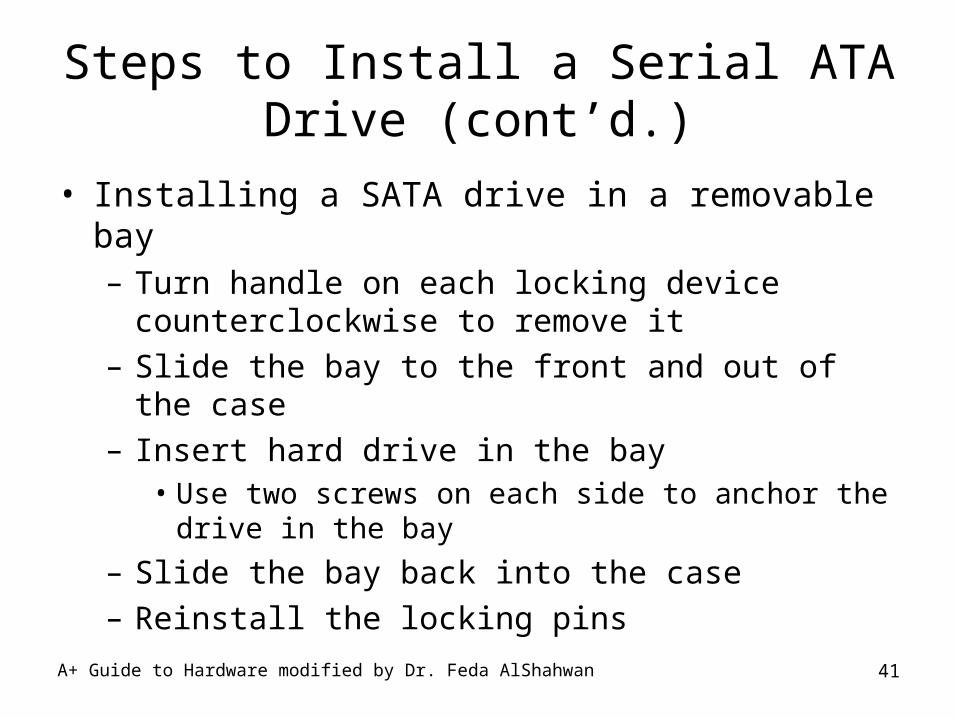
Steps to Install a Serial ATA Drive (cont’d.)
• Installing a SATA drive in a removable bay– Turn handle on each locking device counterclockwise
to remove it– Slide the bay to the front and out of the case– Insert hard drive in the bay
• Use two screws on each side to anchor the drive in the bay
– Slide the bay back into the case– Reinstall the locking pins
A+ Guide to Hardware modified by Dr. Feda AlShahwan 42
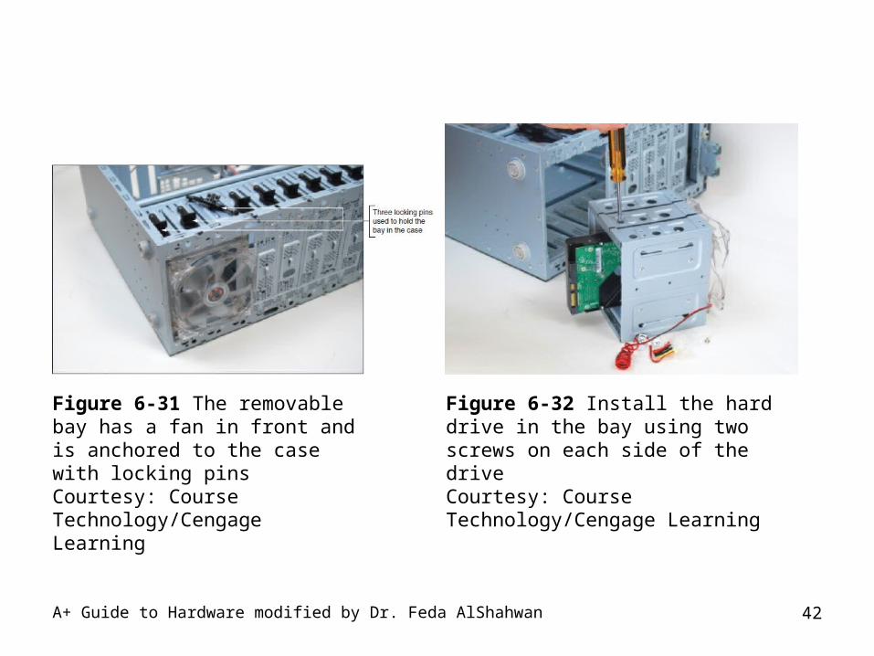
Figure 6-31 The removable bay has a fan in front and is anchored to the case with locking pinsCourtesy: Course Technology/Cengage Learning
Figure 6-32 Install the hard drive in the bay using two screws on each side of the driveCourtesy: Course Technology/Cengage Learning
A+ Guide to Hardware modified by Dr. Feda AlShahwan 43
Steps to Configure and Install a Parallel ATA Drive
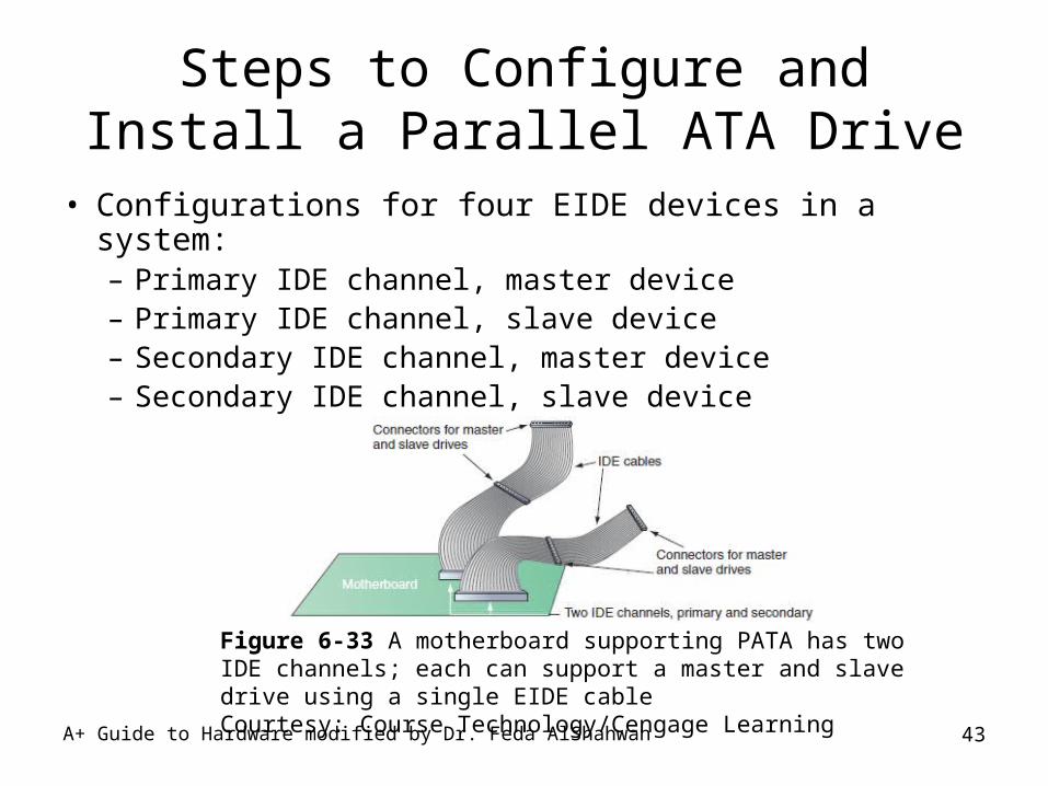
• Configurations for four EIDE devices in a system:– Primary IDE channel, master device– Primary IDE channel, slave device– Secondary IDE channel, master device– Secondary IDE channel, slave device
Figure 6-33 A motherboard supporting PATA has two IDE channels; each can support a master and slave drive using a single EIDE cableCourtesy: Course Technology/Cengage Learning
A+ Guide to Hardware modified by Dr. Feda AlShahwan 44
Steps to Configure and Install a Parallel ATA Drive (cont’d.)
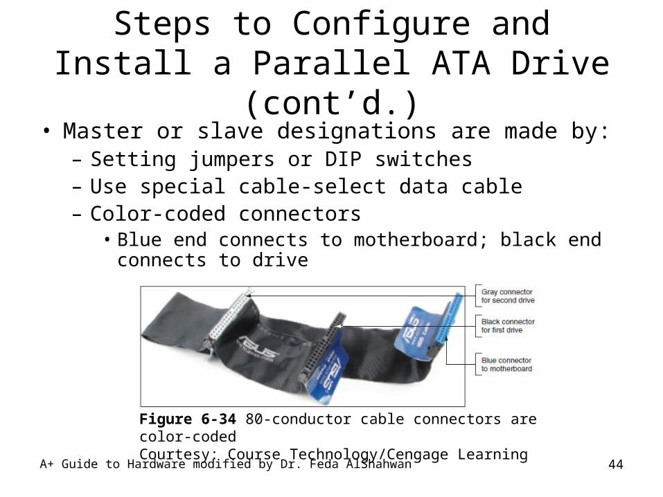
• Master or slave designations are made by:– Setting jumpers or DIP switches – Use special cable-select data cable– Color-coded connectors
• Blue end connects to motherboard; black end connects to drive
Figure 6-34 80-conductor cable connectors are color-codedCourtesy: Course Technology/Cengage Learning
A+ Guide to Hardware modified by Dr. Feda AlShahwan 45
Steps to Configure and Install a Parallel ATA Drive (cont’d.)
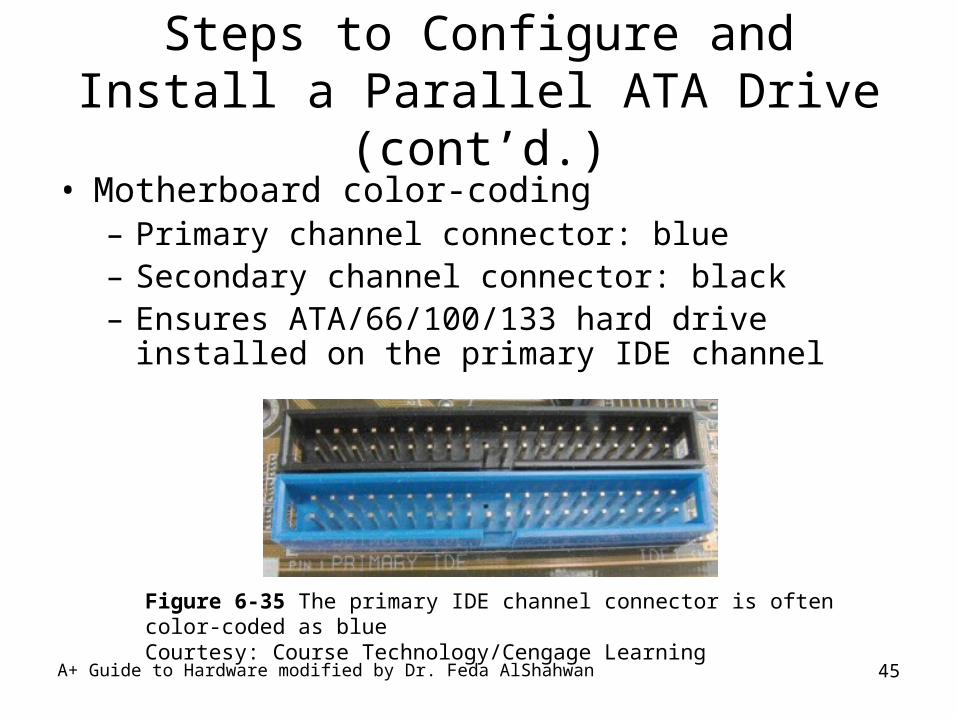
• Motherboard color-coding– Primary channel connector: blue– Secondary channel connector: black– Ensures ATA/66/100/133 hard drive installed on the
primary IDE channel
Figure 6-35 The primary IDE channel connector is often color-coded as blueCourtesy: Course Technology/Cengage Learning
A+ Guide to Hardware modified by Dr. Feda AlShahwan 46
Steps to Configure and Install a Parallel ATA Drive (cont’d.)
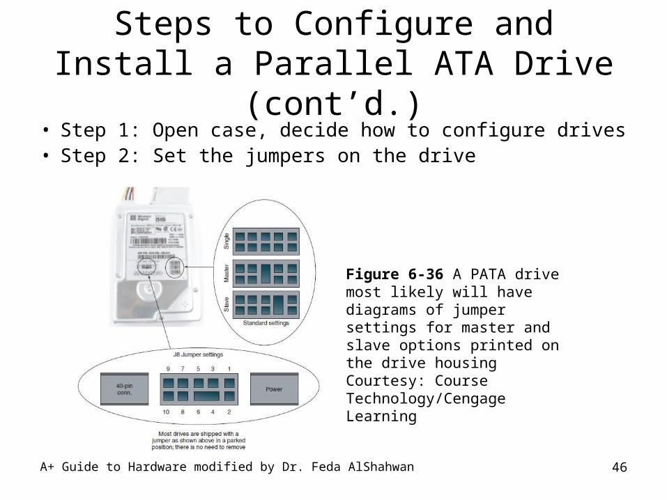
• Step 1: Open case, decide how to configure drives• Step 2: Set the jumpers on the drive
Figure 6-36 A PATA drive most likely will have diagrams of jumper settings for master and slave options printed on the drive housingCourtesy: Course Technology/Cengage Learning
A+ Guide to Hardware modified by Dr. Feda AlShahwan 47
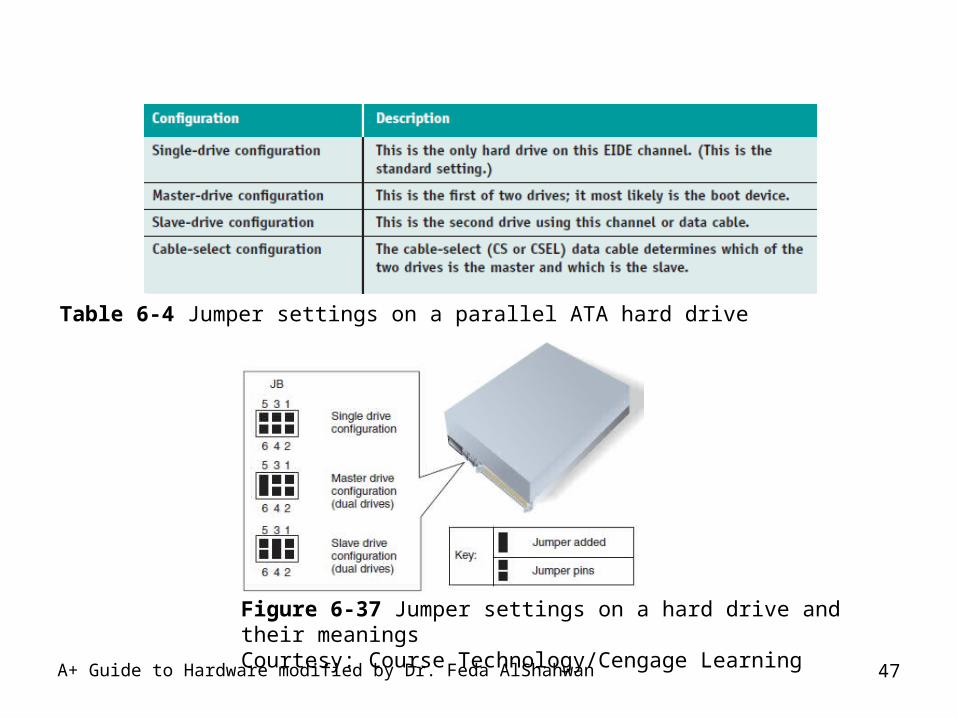
Table 6-4 Jumper settings on a parallel ATA hard drive
Figure 6-37 Jumper settings on a hard drive and their meaningsCourtesy: Course Technology/Cengage Learning
A+ Guide to Hardware modified by Dr. Feda AlShahwan 48
Steps to Configure and Install a Parallel ATA Drive (cont’d.)
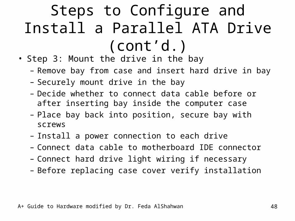
• Step 3: Mount the drive in the bay– Remove bay from case and insert hard drive in bay– Securely mount drive in the bay– Decide whether to connect data cable before or after
inserting bay inside the computer case– Place bay back into position, secure bay with screws– Install a power connection to each drive– Connect data cable to motherboard IDE connector– Connect hard drive light wiring if necessary– Before replacing case cover verify installation

A+ Guide to Hardware modified by Dr. Feda AlShahwan 49
Installing a Hard Drive in a Wide Bay
• Use universal bay kit to securely fit drive into the bay
Figure 6-45 Use the universal bay kit to make the drive fit the bayCourtesy: Course Technology/Cengage Learning
Figure 6-46 Hard drive installed in a wide bay using a universal bay kit adapterCourtesy: Course Technology/Cengage Learning
A+ Guide to Hardware modified by Dr. Feda AlShahwan 50
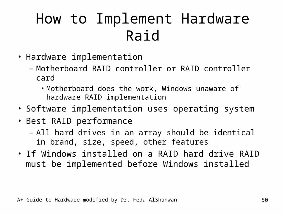
How to Implement Hardware Raid
• Hardware implementation– Motherboard RAID controller or RAID controller card
• Motherboard does the work, Windows unaware of hardware RAID implementation
• Software implementation uses operating system
• Best RAID performance– All hard drives in an array should be identical in
brand, size, speed, other features
• If Windows installed on a RAID hard drive RAID must be implemented before Windows installed
A+ Guide to Hardware modified by Dr. Feda AlShahwan 51
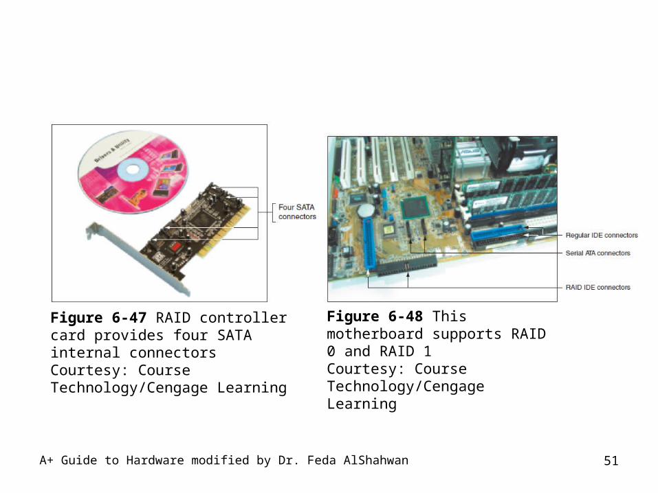
Figure 6-47 RAID controller card provides four SATA internal connectorsCourtesy: Course Technology/Cengage Learning
Figure 6-48 This motherboard supports RAID 0 and RAID 1Courtesy: Course Technology/Cengage Learning
A+ Guide to Hardware modified by Dr. Feda AlShahwan 52
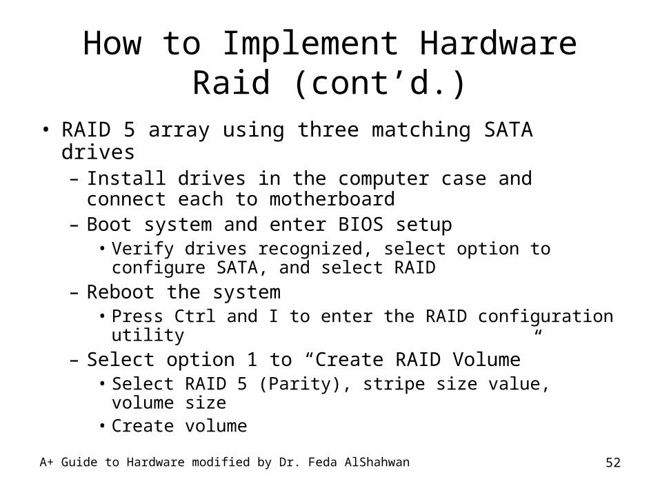
How to Implement Hardware Raid (cont’d.)
• RAID 5 array using three matching SATA drives– Install drives in the computer case and connect each
to motherboard– Boot system and enter BIOS setup
• Verify drives recognized, select option to configure SATA, and select RAID
– Reboot the system• Press Ctrl and I to enter the RAID configuration utility
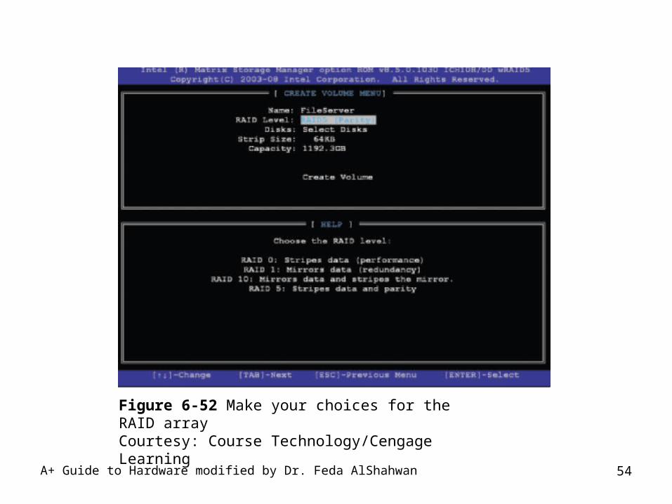
– Select option 1 to “Create RAID Volume”• Select RAID 5 (Parity), stripe size value, volume size• Create volume
A+ Guide to Hardware modified by Dr. Feda AlShahwan 53
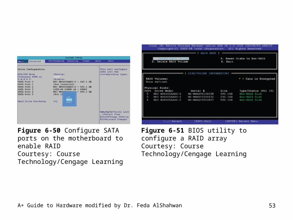
Figure 6-50 Configure SATA ports on the motherboard to enable RAIDCourtesy: Course Technology/Cengage Learning
Figure 6-51 BIOS utility to configure a RAID arrayCourtesy: Course Technology/Cengage Learning
A+ Guide to Hardware modified by Dr. Feda AlShahwan 54
Figure 6-52 Make your choices for the RAID arrayCourtesy: Course Technology/Cengage Learning
A+ Guide to Hardware modified by Dr. Feda AlShahwan 55
How to Implement Hardware Raid (cont’d.)
• RAID 5 array using three matching SATA drives (cont’d.)– Install Windows
• Boot from Windows setup CD or DVD• Windows XP: press F6 and insert the RAID driver CD• Vista: proceed as normal
– Disk Management window• Displays a single drive• BIOS manages RAID array without OS’s awareness
– SAN• Network with primary purpose of providing large
amounts of data storage

A+ Guide to Hardware modified by Dr. Feda AlShahwan 56
Figure 6-53 Vista Disk Management sees the RAID array as a single 500 GB hard driveCourtesy: Course Technology/Cengage Learning
Hard Drive Specifications
Hard disk specifications:The hard drive’s is measured by:•Storage capacity: it is the total formatted storage ability measured in GB or even Terabytes (i.e., 300 GB)•Data transfer rate( Throughput): amount of data transferred from the read/write heads to the CPU measured in MBps (i.e., 133 MBps)•Seek time: Time it takes for the head to move to the rght track is the seek time typically 8 to 4 ms
A+ Guide to Hardware modified by Dr. Feda AlShahwan 57
Hard Drive Specifications
• Rotational latency time: Average time to locate a specific sector on the drive. The rotational delay is the time required for the addressed area of the disk (or cylinder) to rotate into a position where it is accessible by the read/write head and measured in ms.
• Average access Time: The summations of average seek time and the latency.
• ACCESS TIME = SEEK TIME (Time to move to the cylinder) + ROTATIONAL LATENCY TIME (Time to wait for sector)
A+ Guide to Hardware modified by Dr. Feda AlShahwan 58
Hard Drive Specifications• Interleave (Rotational Speed): Is the average number
of revolutions per minute (i.e., 7200 rpm). How many revolutions the platters will rotate under the read/write heads per minute. Measured in RPM. Range between 4,200rpm to 15,000rpm. Standard IDE hard disk drive being 7,200 rpm while SCSI hard disk drives being 10,000rpm and now 15,000rpm.
• Arial Density: Measured in bytes/sq. inch. Refers to how densely packed the information is on the hard disk drives platters is. Higher densities give greater storage per size and reduce time to get the data.
A+ Guide to Hardware modified by Dr. Feda AlShahwan 59
Hard Drive Specifications
• MTBF: Mean Time Between Failures, measured in hours, is meant to represent the average amount of time that will pass between random failures on a drive of a given type. It is usually in the range of 300,000 to 1,200,000 hours for modern drives today (with the range increasing every few years) and is specified for almost every drive. The higher the better. IDE hard disk drives tend to be lower than SCSI hard disk drives.
• Platter: it is the circular disks on which the magnetic data are stored. Actual disk of a hard disk drive and drives can and do have more than one platter.
A+ Guide to Hardware modified by Dr. Feda AlShahwan 60
A+ Guide to Hardware modified by Dr. Feda AlShahwan 61
Steps to Install a Floppy Drive
• Turn off the computer, unplug power cord, press power button, and remove cover
• Unplug power cable and data cable from old drive• Unscrew and dismount drive• Slide new drive into the bay
– Screw new drive down with the same screws• Connect floppy drive data cable to motherboard• Connect data cable and power cord to the drive• Replace cover, turn on computer, and enter BIOS
setup to verify installation
A+ Guide to Hardware modified by Dr. Feda AlShahwan 62
Troubleshooting Hard Drives
• Problems:– With hard drive installations– Occurring after the installation with hard drives and
floppy drives– With booting the PC
• Caused by hard drive hardware
A+ Guide to Hardware modified by Dr. Feda AlShahwan 63
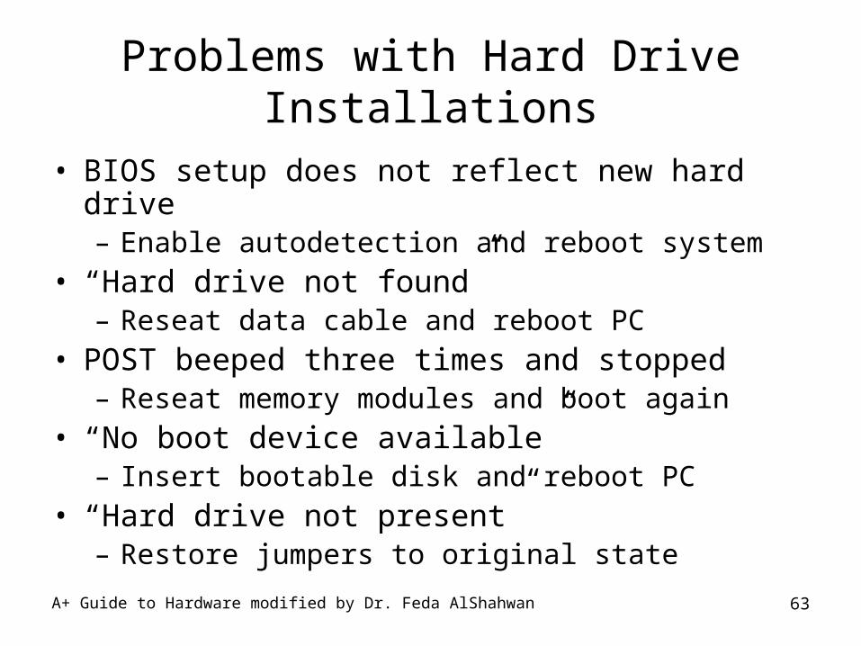
Problems with Hard Drive Installations
• BIOS setup does not reflect new hard drive– Enable autodetection and reboot system
• “Hard drive not found”– Reseat data cable and reboot PC
• POST beeped three times and stopped– Reseat memory modules and boot again
• “No boot device available”– Insert bootable disk and reboot PC
• “Hard drive not present”– Restore jumpers to original state
A+ Guide to Hardware modified by Dr. Feda AlShahwan 64
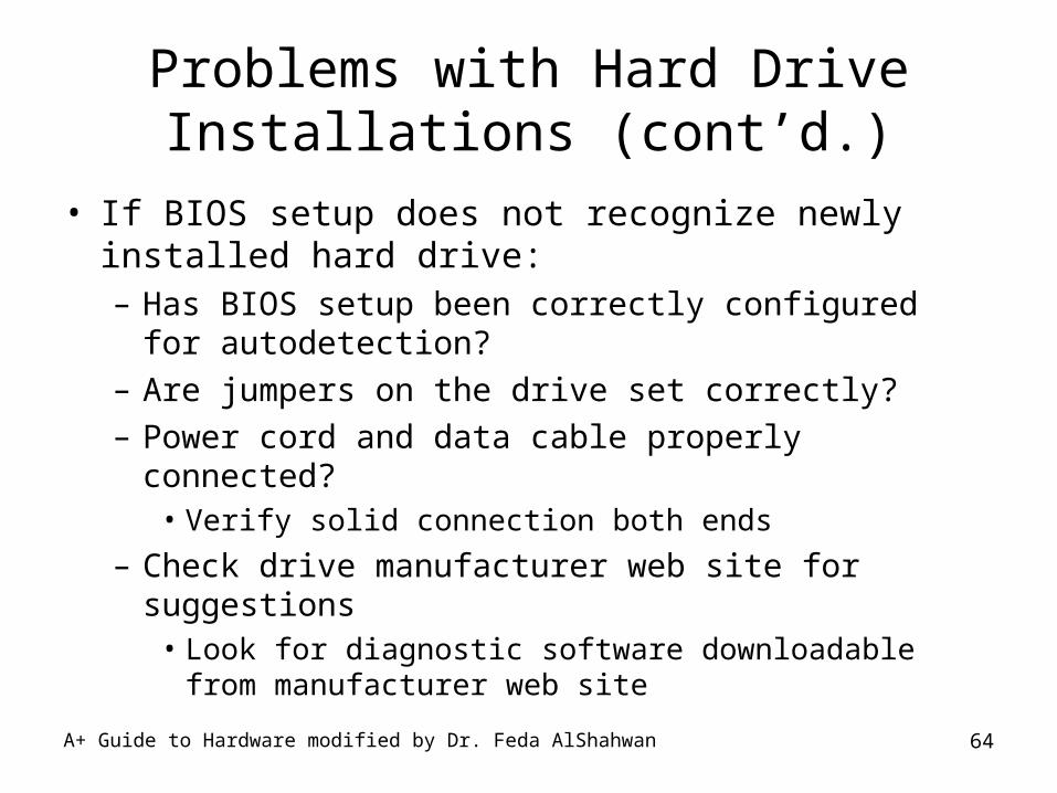
Problems with Hard Drive Installations (cont’d.)
• If BIOS setup does not recognize newly installed hard drive:– Has BIOS setup been correctly configured for
autodetection?– Are jumpers on the drive set correctly?– Power cord and data cable properly connected?
• Verify solid connection both ends
– Check drive manufacturer web site for suggestions• Look for diagnostic software downloadable from
manufacturer web site
A+ Guide to Hardware modified by Dr. Feda AlShahwan 65
How to Approach a Hard Drive Problem after the Installation
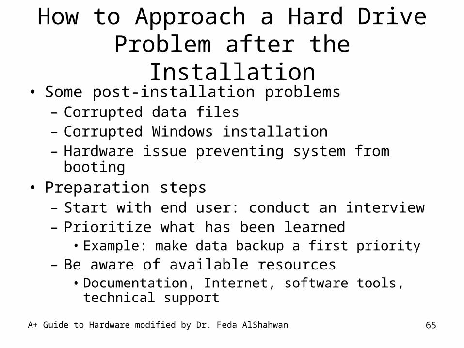
• Some post-installation problems – Corrupted data files– Corrupted Windows installation– Hardware issue preventing system from booting
• Preparation steps– Start with end user: conduct an interview– Prioritize what has been learned
• Example: make data backup a first priority– Be aware of available resources
• Documentation, Internet, software tools, technical support
A+ Guide to Hardware modified by Dr. Feda AlShahwan 66
Boot Problems Caused By Hard Drive Hardware
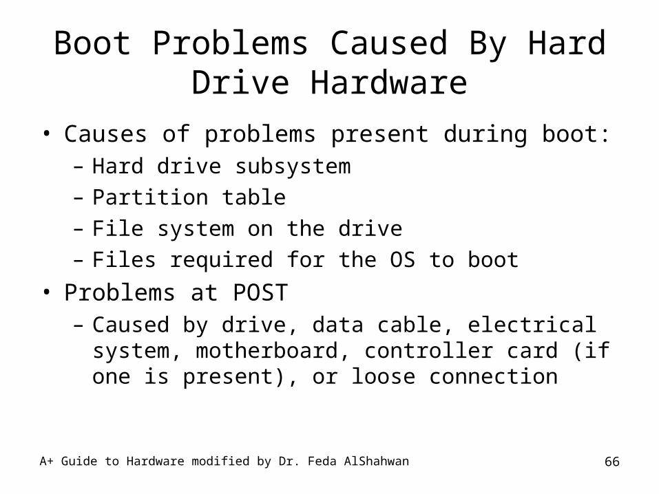
• Causes of problems present during boot:– Hard drive subsystem– Partition table – File system on the drive – Files required for the OS to boot
• Problems at POST – Caused by drive, data cable, electrical system,
motherboard, controller card (if one is present), or loose connection
A+ Guide to Hardware modified by Dr. Feda AlShahwan 67
Boot Problems Caused By Hard Drive Hardware (cont’d.)
• Problems at POST, checks:– BIOS manufacturer website for error code explanation– BIOS utility RAID utility– BIOS setup: ability to disable block mode– Remove and reattach all drive cables
• Check for correct pin-1 orientation
– Remove and reseat controller card– Check drive jumper settings– Inspect drive for damage– Determine if the hard drive is spinning
A+ Guide to Hardware modified by Dr. Feda AlShahwan 68
Boot Problems Caused By Hard Drive Hardware (cont’d.)
• Problems at POST, checks (cont’d.):– Check cable for frayed edges or other damage– Check the installation manual– Be sure power cable, drive data cable connections
are good– Check BIOS setup for errors in the hard drive
configuration– Try booting from another media– Check drive manufacturer Web site for diagnostic
software– Create a boot CD with hard drive diagnostic software

A+ Guide to Hardware modified by Dr. Feda AlShahwan 69
Boot Problems Caused By Hard Drive Hardware (cont’d.)
• Problems at POST, checks (cont’d.):– Exchange three field replaceable units
• Data cable, adapter card (optional), hard drive
– If hard drive refuses to work but its light stays • Problem might be a faulty controller
– Sometimes older drives refuse to spin at POST
A+ Guide to Hardware modified by Dr. Feda AlShahwan 70
Boot Problems Caused By Hard Drive Hardware (cont’d.)
• Bumps are bad – A scratched surface may cause a hard drive crash– Data may be recovered, even if drive is inaccessible
• Invalid drive or drive specification– System BIOS cannot read partition table information– Boot from recovery CD and check partition table
• Bad sector errors– Problem due to fading tracks and sectors
• Replace the drive
A+ Guide to Hardware modified by Dr. Feda AlShahwan 71
Boot Problems Caused By Hard Drive Hardware (cont’d.)
• Solid state drives– No concerns with bumping the drive while it is in use– May or may not need formatting– If drive gives errors:
• Try using manufacturer diagnostic software
• Check manufacturer Web site support section for troubleshooting tips
– SATA and PATA connections and BIOS settings for solid state drives
• Look and work the same as for other drives
A+ Guide to Hardware modified by Dr. Feda AlShahwan 72
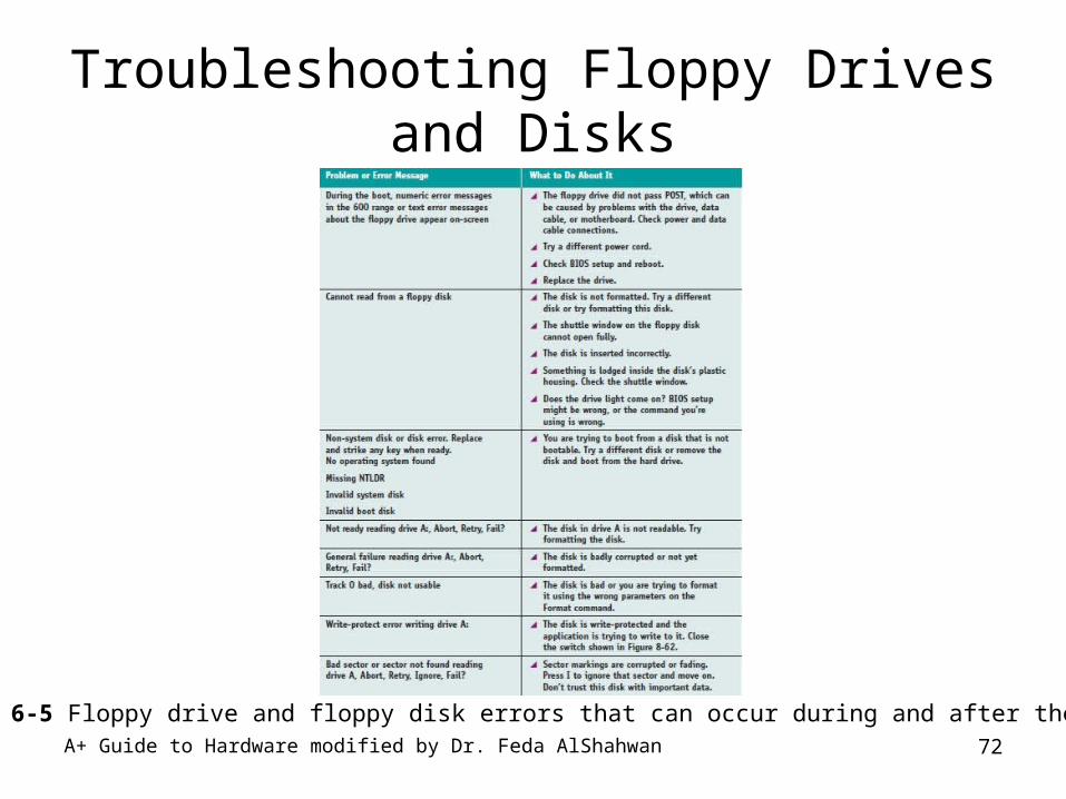
Troubleshooting Floppy Drives and Disks
Table 6-5 Floppy drive and floppy disk errors that can occur during and after the boot

A+ Guide to Hardware modified by Dr. Feda AlShahwan 73
Periodic Maintenance of HDDScanDisk:•ScanDisk is a Windows®9x utility that checks your hard drive for physical damage and also fixes file system errors, such as cross-linked folders, damaged or invalid file names and disassociated file names. In Windows®XP®, the utility is called Check Disk.
Accessing ScanDisk•To access ScanDisk, click Start > Programs > Accessories >System Tools > ScanDisk. Select the drive that you want to scan (usually C:) and choose the type of test.
A+ Guide to Hardware modified by Dr. Feda AlShahwan 74
Periodic Maintenance of HDD
The test types are: •Standard - inspects the drive for lost chains/clusters (The drive's map, which tells it where to find files can't find the pointer (directions) to the file.) This test typically takes only a few mintues. •Thorough - does the same test as the Standard test, and, in addition, checks the drive for bad sectors. When ScanDisk finds a bad sector, it will mark the sector as bad, avoid using it and move data to a good spot on the drive. You will have to observe the process and follow the instructions on the screen. The Thorough test takes considerably longer to complete than the Standard test.
A+ Guide to Hardware modified by Dr. Feda AlShahwan 75
Periodic Maintenance of HDDBefore running ScanDisk•ScanDisk will repeatedly restart, never finishing the hard drive scan, if there is any disk activity on the drive that it is checking. First, close all open programs before running ScanDisk. Don't forget to turn your screen saver, if any, off. Temporarily disable anti-virus software. Unplug network connections, if any, by physically removing the RJ-45 connector from the network interface card. Next, check for programs running in the background by bringing up Task Monitor (simultaneously press <Ctrl> <Alt> <Del> keys), click the Applications tab and close (End Task) all programs, except Explorer and Systray. Now access ScanDisk and run the utility. An alternative to using Task Manager to close programs is to start your computer in Safe Mode. Disable your screen saver, if any. Start or restart your computer and as it starts to boot immediately tap the <F8> or <Ctrl> key until you see an options screen. Choose Safe Mode and hit the <Enter> key. Click OK when the dialog box appears advising you that Windows® is operating in Safe Mode. Don't be alarmed if your desktop looks different from the normal desktop. (In Safe Mode, Windows® loads a minimal set of drivers, including a Standard VGA driver that sets your screen resolution to 640 x 480 pixels with low (8-bit) color.) Now access ScanDisk.
A+ Guide to Hardware modified by Dr. Feda AlShahwan 76
Periodic Maintenance of HDDRunning Check Disk from Windows Explorer
To run Check Disk: •Click Start and select a My Computer window for the drive that you want to examine (usually C). •Right click the icon for the drive that you want to check (again, usually C) > select Properties and on the Tools tab click Check Now. •Unless you just want to see a report of file system errors (no action taken to correct errors), put a check in one of the following options:
– Automatically Fix File System Errors. This option is straightforward. If it is not selected, file system errors are reported, but not fixed.
– Scan For And Attempt Recovery Of Bad Sectors. In addition to automatically repairing file system errors, selecting this option causes the utility to perform a thorough check of the entire drive, locate bad sectors and try to recover data stored in bad sectors. If you select this option, you may find that it takes the utility quite a few hours to complete its work.
A+ Guide to Hardware modified by Dr. Feda AlShahwan 77
Periodic Maintenance of HDD• Click the Start button.
• If the drive that you want to fix is the system drive, there will be open files on the drive. You will see a dialog box announcing that the utility needs exclusive access to operate and can't gain that access unless you re-start your computer. Click Yes.
• XP will re-start in character mode, meaning that you can't do anything other than run the utility. Unless you strike any key within ten seconds of seeing the restricted boot messsage, Check Disk will run.
• After Check Disk has finished, you will either see Disk Check Complete (no errors) or a list of errors and repairs.
A+ Guide to Hardware modified by Dr. Feda AlShahwan 78
Periodic Maintenance of HDD• Running Check Disk from command prompt
• To run Check Disk from the command prompt: Start > Run > type cmd and hit the <Enter> key. At the command prompt, type chkdsk, then <Enter>. This command does not fix or repair. If you want to fix, repair or both fix and repair, you must use a switch for the chddsk command. If you use a switch, the disk must be locked and the command with a switch or switches will be run when you re-start the computer. The two most commonly used switches are:
• /F - fixes errors.
• /R - marks bad sectors and tries to recover data.
A+ Guide to Hardware modified by Dr. Feda AlShahwan 79
Periodic Maintenance of HDD• Frequency• It is recommended that you run ScanDisk/Check Disk
every 30 days. • Using ScanDisk/Check Disk and Disk Defragmenter• Run ScanDisk/Check Disk first, followed by Disk
Defragmenter.
A+ Guide to Hardware modified by Dr. Feda AlShahwan 80
Periodic Maintenance of HDDDisk Defragmenter:•Disk Defragmenter is a utility included in all versions of Windows® after Windows® 95®. Data is written to open spaces on the hard disk. If the open space is not sufficient to contain all the data, another open space will be found and the balance of the data will be written there. If the contents of a file are written to several sectors on the hard drive, it will take longer to open the file. Since data is constantly being written to and deleted from the hard drive, gaps that impair performance develop. Disk Defragmenter is designed to reorganize the data on your hard drive so that your computer runs faster and more efficiently.
A+ Guide to Hardware modified by Dr. Feda AlShahwan 81
Periodic Maintenance of HDDAccessing Disk Defragmenter:•To access Disk Defragmeter, click Start > Programs > Accessories >System Tools > Disk Defragmenter.
Before running Disk Defragmeter•Before running Disk Defragmenter, follow the procedures listed in the 'Before running ScanDisk' instructions.•Free space•You must have at least 15% free space on you hard drive to successfully run Disk Defragmenter. If you have insufficient free space, try running the Disk Cleanup utility.
A+ Guide to Hardware modified by Dr. Feda AlShahwan 82
Periodic Maintenance of HDDTime to complete process•While the time depends on the size of your hard disk and speed of your processor, it will typically take several hours (or more) for the hard disk to be defragmented. During the defragmentaion process, you cannot use your computer for any other applications.
Frequency•It is recommended that you run Disk Defragmenter every 30 days.
A+ Guide to Hardware modified by Dr. Feda AlShahwan 83
Summary
• Hardware technologies inside the drive– Solid state or magnetic
• Hard drive disk surface divided into concentric circles (tracks)– Track divided into 512-byte segments (sector, record)
• Current internal hard drives methods– Parallel ATA (PATA), Serial ATA (SATA), SCSI
• External hard drive methods– External SATA (eSATA), SCSI, FireWire, USB, Fibre
Channel
A+ Guide to Hardware modified by Dr. Feda AlShahwan 84
Summary (cont’d.)
• RAID: two or more hard drives work together as an array of drives– Improves fault tolerance and performance
• Floppy disk drive (FDD) holds only 1.44 MB of data– Useful when recovering from a failed BIOS update– Inexpensive, easy transfer of small data amounts
• Hard drive must match OS and motherboard– BIOS uses autodetection to prepare the device
• Installing a hard drive– Usually not difficult, keep a cool head