160n turbine engine - jet modellers association of ireland manual.pdf · feedback as our brief, ......
TRANSCRIPT
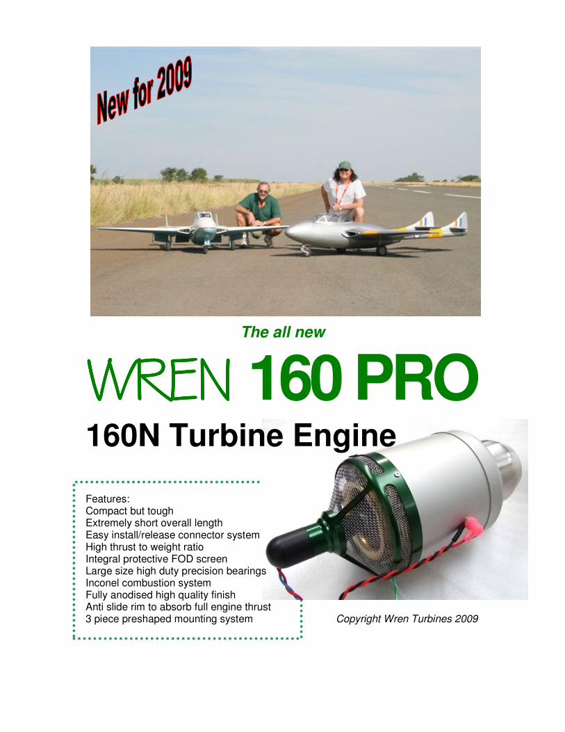
The all new
WREN WREN WREN WREN 160 PRO 160N Turbine Engine
Features: Compact but tough Extremely short overall length Easy install/release connector system High thrust to weight ratio Integral protective FOD screen Large size high duty precision bearings Inconel combustion system Fully anodised high quality finish Anti slide rim to absorb full engine thrust 3 piece preshaped mounting system Copyright Wren Turbines 2009
Wren 160PRO TurboJet Engine Page 1
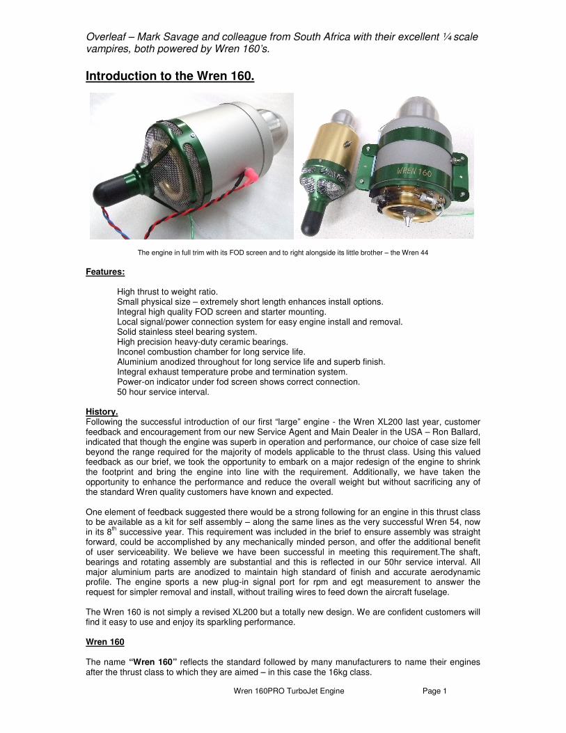
Overleaf – Mark Savage and colleague from South Africa with their excellent ¼ scale vampires, both powered by Wren 160’s.
Introduction to the Wren 160.
The engine in full trim with its FOD screen and to right alongside its little brother – the Wren 44
Features:
High thrust to weight ratio. Small physical size – extremely short length enhances install options. Integral high quality FOD screen and starter mounting. Local signal/power connection system for easy engine install and removal. Solid stainless steel bearing system. High precision heavy-duty ceramic bearings. Inconel combustion chamber for long service life. Aluminium anodized throughout for long service life and superb finish. Integral exhaust temperature probe and termination system. Power-on indicator under fod screen shows correct connection. 50 hour service interval.
History. Following the successful introduction of our first “large” engine - the Wren XL200 last year, customer feedback and encouragement from our new Service Agent and Main Dealer in the USA – Ron Ballard, indicated that though the engine was superb in operation and performance, our choice of case size fell beyond the range required for the majority of models applicable to the thrust class. Using this valued feedback as our brief, we took the opportunity to embark on a major redesign of the engine to shrink the footprint and bring the engine into line with the requirement. Additionally, we have taken the opportunity to enhance the performance and reduce the overall weight but without sacrificing any of the standard Wren quality customers have known and expected. One element of feedback suggested there would be a strong following for an engine in this thrust class to be available as a kit for self assembly – along the same lines as the very successful Wren 54, now in its 8
th successive year. This requirement was included in the brief to ensure assembly was straight
forward, could be accomplished by any mechanically minded person, and offer the additional benefit of user serviceability. We believe we have been successful in meeting this requirement.The shaft, bearings and rotating assembly are substantial and this is reflected in our 50hr service interval. All major aluminium parts are anodized to maintain high standard of finish and accurate aerodynamic profile. The engine sports a new plug-in signal port for rpm and egt measurement to answer the request for simpler removal and install, without trailing wires to feed down the aircraft fuselage. The Wren 160 is not simply a revised XL200 but a totally new design. We are confident customers will find it easy to use and enjoy its sparkling performance. Wren 160 The name “Wren 160” reflects the standard followed by many manufacturers to name their engines after the thrust class to which they are aimed – in this case the 16kg class.
Wren 160PRO TurboJet Engine Page 2
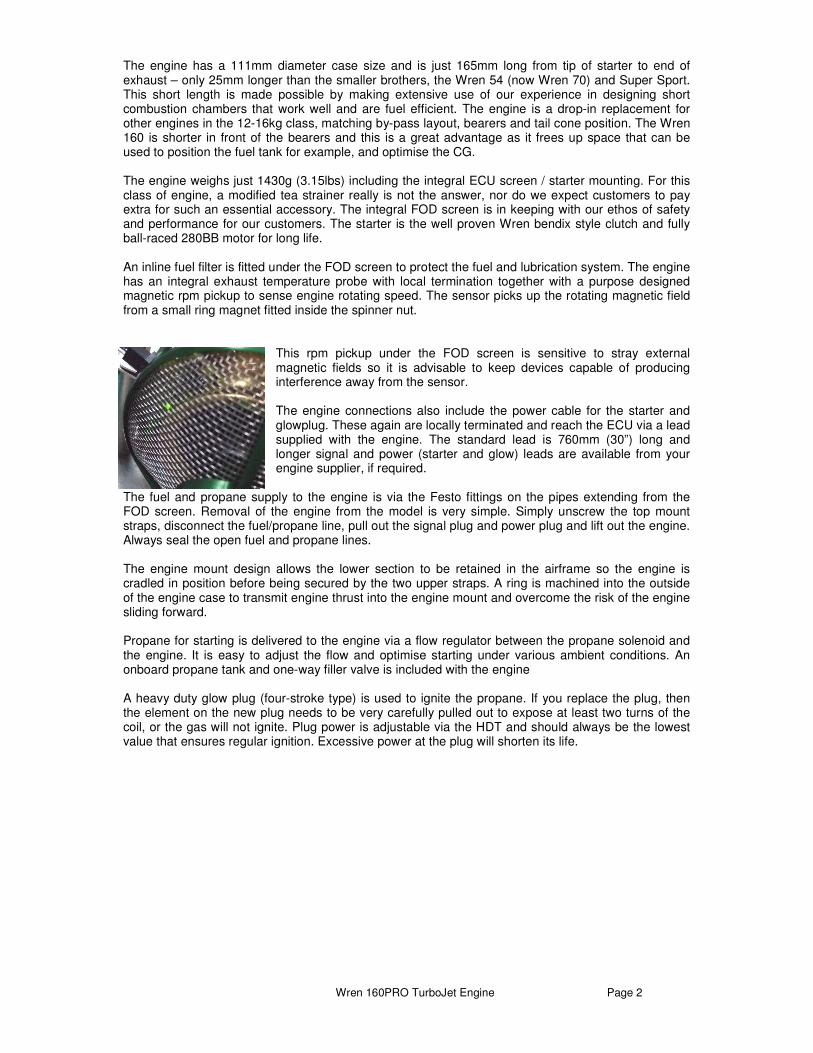
The engine has a 111mm diameter case size and is just 165mm long from tip of starter to end of exhaust – only 25mm longer than the smaller brothers, the Wren 54 (now Wren 70) and Super Sport. This short length is made possible by making extensive use of our experience in designing short combustion chambers that work well and are fuel efficient. The engine is a drop-in replacement for other engines in the 12-16kg class, matching by-pass layout, bearers and tail cone position. The Wren 160 is shorter in front of the bearers and this is a great advantage as it frees up space that can be used to position the fuel tank for example, and optimise the CG. The engine weighs just 1430g (3.15lbs) including the integral ECU screen / starter mounting. For this class of engine, a modified tea strainer really is not the answer, nor do we expect customers to pay extra for such an essential accessory. The integral FOD screen is in keeping with our ethos of safety and performance for our customers. The starter is the well proven Wren bendix style clutch and fully ball-raced 280BB motor for long life. An inline fuel filter is fitted under the FOD screen to protect the fuel and lubrication system. The engine has an integral exhaust temperature probe with local termination together with a purpose designed magnetic rpm pickup to sense engine rotating speed. The sensor picks up the rotating magnetic field from a small ring magnet fitted inside the spinner nut.
This rpm pickup under the FOD screen is sensitive to stray external magnetic fields so it is advisable to keep devices capable of producing interference away from the sensor. The engine connections also include the power cable for the starter and glowplug. These again are locally terminated and reach the ECU via a lead supplied with the engine. The standard lead is 760mm (30”) long and longer signal and power (starter and glow) leads are available from your engine supplier, if required.
The fuel and propane supply to the engine is via the Festo fittings on the pipes extending from the FOD screen. Removal of the engine from the model is very simple. Simply unscrew the top mount straps, disconnect the fuel/propane line, pull out the signal plug and power plug and lift out the engine. Always seal the open fuel and propane lines. The engine mount design allows the lower section to be retained in the airframe so the engine is cradled in position before being secured by the two upper straps. A ring is machined into the outside of the engine case to transmit engine thrust into the engine mount and overcome the risk of the engine sliding forward. Propane for starting is delivered to the engine via a flow regulator between the propane solenoid and the engine. It is easy to adjust the flow and optimise starting under various ambient conditions. An onboard propane tank and one-way filler valve is included with the engine A heavy duty glow plug (four-stroke type) is used to ignite the propane. If you replace the plug, then the element on the new plug needs to be very carefully pulled out to expose at least two turns of the coil, or the gas will not ignite. Plug power is adjustable via the HDT and should always be the lowest value that ensures regular ignition. Excessive power at the plug will shorten its life.

Wren 160PRO TurboJet Engine Page 3
Safety Notes. Wren Turbines are active members of BMFA (British Model Flying Association) and fully endorse the BMFA code of practice for operating gas turbines. The BMFA also provides insurance cover for modellers in the UK. This Code of Practice may be accessed from the Gas Turbine Builders Association (GTBA) website on www.gtba.co.uk The GTBA is the BMFA advisory body for model gas turbines. Failsafe. Please read carefully the notes on setting the failsafe on your radio to ensure safe operation in event of interference or loss of signal. It is advised always to have a CO
2 or similar gas-type fire extinguisher with you when running the
engine – you never know when an emergency will strike and it is best to be prepared. If you need to extinguish an onboard fire you should point the extinguisher into the front of the engine and not in through the turbine end as this may simply blow the flame into the model. Always ensure, when running a gas turbine that you keep spectators at least 10m (30ft) clear of the area to the side and rear of the engine as you would a propeller engine, as although a broken turbine is extremely rare it is still technically possible and it is better to be safe. When running the engine you should stand slightly in front and to one side of the engine, and not to the side for the reason above. Always wear ear defenders when running the engine as gas turbines have a high intensity noise level close to the engine that can impair your hearing in time. Never try to improve/speed up the starting of the engine by spraying ignition agents into the engine – a dangerous flashback fire may result and you will in any case never improve the starting this way. This engine is not a toy and can cause bodily harm to you or others if misused. It is your responsibility as owner, to ensure safe, careful and considerate operation of your engine at all times, and in accordance with the manufacturers instructions. If you sell or give away this engine, please pass these instructions to the new owner. This engine must only be run firmly attached to a secure and sturdy engine test stand or model installation where the model is suitably restrained. The thrust generated is considerable and mountings must be sufficient to withstand such forces. Use appropriate screws and lock-nuts. The engine must never be run held in the hand or clamped in a vice. This engine is an internal combustion gas turbine engine which generates large quantities of heat – ensure the mountings and installation are appropriate for operation at these elevated temperatures. During operation and for a time afterwards there are parts of the engine which are hot enough to cause serious burns – do not touch any part of the engine until it has cooled to room temperature. Always operate your engine in open air away from confined spaces as the engine exhaust contains gases which can cause asphyxiation and nuisance from smells. The exhaust gases are very hot (over 650’C) on leaving the engine and can cause burns to skin or damage to objects close to it – keep exhausts clear of anything which is affected by such heat. This engine must not be used near flammable gases, liquid or materials.
Wren 160PRO TurboJet Engine Page 4
Always keep a CO2 fire extinguisher close by when operating this engine. Turbine fuel is poisonous. Keep it away from the mouth and eyes and from contact with skin. Always store it in a marked container and out of reach to children. Turbine fuel has a relatively high flash-point but in certain circumstances (ie if allowed to contact hot surfaces) can be highly flammable or even explosive. Keep it away from heat and sources of combustion. The starting gas is highly flammable and must be used with extreme care. Maintain canister and fittings in good leak-proof condition. Protect from sunlight and prevent exposure to temperatures exceeding 50’C. Keep out of reach of children. Discard used canisters in a safe place and do not puncture or incinerate, even when empty. Avoid deliberate inhalation. Ensure gas only is supplied the engine, liquid gas must not be allowed to pass into the engine. Gas supply must be disconnected until ready for immediate use. Gas is heavier than air and can fill a model if allowed to leak unchecked, and become a potential explosion hazard. Turbine oil can be are hazardous to health and must not be allowed to come into contact with skin, mouth, eyes or through ingestion, accidental or otherwise. Take care when decanting and ensure any spillage is wiped away immediately and clean any affected area with warm soapy water. Wash hands and any affected part immediately after any contact. Turbine oil can discolour or affect certain paint finishes as may be used. Take precautions to prevent spillage. Do not discard or allow any spillage to run into drains. If removing the glow-plug to test it, keep fingers or bare skin away from possible burn from the glowing element – use a metal tool or appropriate insulation. As operator, it is your responsibility to ensure any spectators (especially small children) or helpers are kept well away from the engine whilst it is operating. The safest position to operate the engine is directly in front. The area inline and to the rear of the turbine is the most dangerous area and you must keep well clear of this. Keep all spectators away from the side and rear of the engine to a distance of at least 10mtrs (30ft) radius, as shown. If operating from a pit area take special care as safety distances are often difficult to maintain. Consider the high engine noise level when spectators are around and do not use high throttle levels in these circumstances. Keep all helpers close by and brief them fully on their duties before starting the engine. One helper should carry out the role of fireman. Ensure they are aware of what to do in event of emergency and where to position the extinguisher if required. Do not attempt to alter the starting characteristics of the engine by spraying ignition agents into the intake, as might be used for gasoline and diesel engines. A dangerous fire and flashback may result.
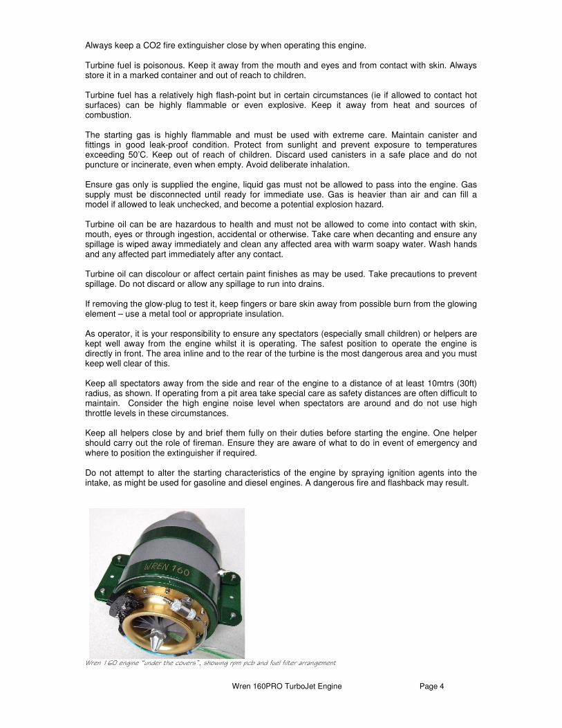
Wren 160 engine “under the covers”, showing rpm pcb and fuel filter arrangement

Wren 160PRO TurboJet Engine Page 5
Wren 160PRO package contents The engine package contains the following: This Operators Manual Wren 160 engine 3 piece engine mounting ProJET “Hornet-111” ecu ProJET Data Terminal Input/Output board Fuel pump c/w mounting Propane valve c/w restrictor, push-on nipple input, 3mm quick release output One-way filling valve Onboard propane tank Fuel (kero) valve – push-on nipple input, 3mm quick release fitting output 3-core engine to ecu power cable LiPo battery Battery to ecu cable 0.3m 1m clear 3mm pipe 1m green 3mm pipe 0.3m Tygon 0.3m green 4mm 0.3m clear 4mm Signal cable 0.3m, ecu to I/O board Signal cable 1m, engine to ecu Signal cable, 0.5m, I/O board to Data Terminal (Spare/additional cables and pipes available on request) Setting Up. A 2-cell LiPo battery pack is supplied with the engine. Always disconnect the battery from the ECU before charging. Charging with battery connected to ECU can destroy the ECU and this will not be covered by the warranty. Charge the pack with a charger especially set up for LiPo batteries. Chargers for any other batteries MUST NOT be used and can cause the battery to explode. A larger capacity pack can be substituted if required. After the flying session is finished, disconnect the battery to prevent it from damage caused by deep discharging. Fuel. The engine is designed to run on Jet A or Jet A1 or paraffin such as is available at airfields and DIY stores or at filling stations from the pump. A system of decanting the fuel safely into the fuel tank must be arranged. Do not use open-top fuel tanks which could fall over or be unstable when filled. When decanting fuel, take precautions to ensure no solid particles or water droplets are carried over into your fuel tank – use an effective filter system. Note that it is common for water to collect in the bottom of fuel containers – ensure this cannot be sucked into the fuel system, by regular visual checks. If necessary, drain the contents and discard the water residue in a safe and responsible manner. Note that jet fuels and oils should not be allowed to come into skin contact so wear suitable gloves and take extra care when handling. Oil. To this fuel must be added 5% oil, ie a mixture of around 20:1 fuel to oil. Suitable oils are turbine oils such as Mobil JetOil, Aeroshell 500/550 and Exxon 2380. Other oils specifically for use in turbine engines and which will mix readily with the fuel and stay mixed, may also be used, for example 2 stroke motor cycle oil has been used very successfully.

Wren 160PRO TurboJet Engine Page 6
Setting up the engine. The engine and its accessories have already been set up and run at least three times so experienced modellers may proceed and install the engine directly to their airplane. Pay heed to the notes on intake requirements and mounting. For less experienced modellers it is suggested to set the engine up on a test-stand and to familiarise themselves with starting and running the engine before installing in a model. A three-piece mounting strap is supplied and this should be strongly attached to a pair of timber battens screwed to a base-board. The two top straps must fit securely on the engine to prevent the casing sliding. Note there is a ridge formed into the rear of the case of the engine which the strap locates against and which the engine thrust pushes against. The various components can be temporarily secured to the baseboard, but be careful not to allow any cables or pipes to run close to the engine intake where they might be sucked against the FOD screen. Remember, this engine produces 16kg (35lbs) of thrust and it can push over the test stand unless it is very secure. Setting up in the model Intake considerations. The Wren 160 consumes a considerable volume of air and the intake area must be large enough. The mass flow of the engine is 0.365kg/sec - just over 280ltrs per second and all this must pass through the intake and exhaust system. The minimum size for a square inlet is 113mm x 113mm or 4-1/2” x 4-1/2”. A single circular opening would need to be 127mm (just over 5”) diameter to have the same area. This inlet area can be achieved through a number of openings but need to be uncluttered and free of internal restrictions especially in the immediate area of the engine intake grille.
If a Wren tailpipe is fitted then you must leave a gap of 25 to 30mm between the end of the engine exhaust nozzle and start of the tailpipe bellmouth. This ensures adequate secondary air can be induced into the tailpipe and enable a small increase in throughput to be achieved without causing restriction in the airflow of the engine. Too small a gap can cause reduced thrust, excessive running temperature and unstable running. Where the engine is exposed- on a KingCat for example- parts of the airframe may need to be protected from heat damage. Temporary protection may be required during starting.
Wren 160PRO TurboJet Engine Page 7
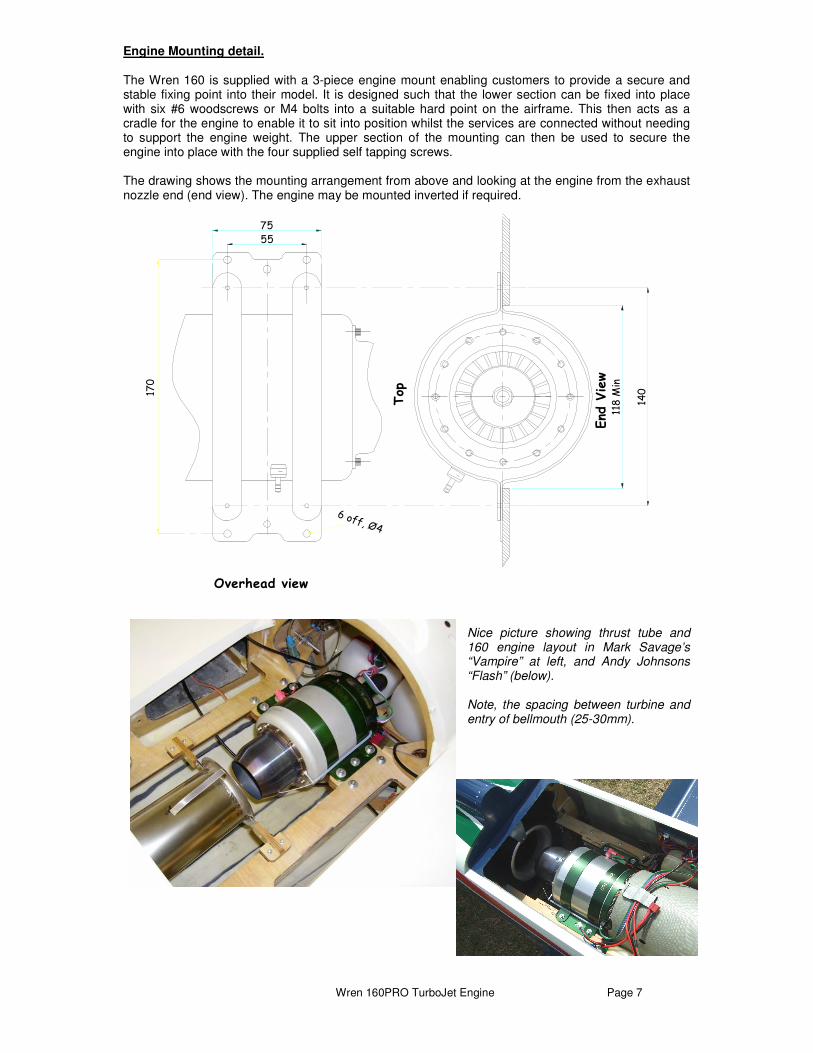
Engine Mounting detail. The Wren 160 is supplied with a 3-piece engine mount enabling customers to provide a secure and stable fixing point into their model. It is designed such that the lower section can be fixed into place with six #6 woodscrews or M4 bolts into a suitable hard point on the airframe. This then acts as a cradle for the engine to enable it to sit into position whilst the services are connected without needing to support the engine weight. The upper section of the mounting can then be used to secure the engine into place with the four supplied self tapping screws. The drawing shows the mounting arrangement from above and looking at the engine from the exhaust nozzle end (end view). The engine may be mounted inverted if required.
Nice picture showing thrust tube and 160 engine layout in Mark Savage’s “Vampire” at left, and Andy Johnsons “Flash” (below). Note, the spacing between turbine and entry of bellmouth (25-30mm).
55
118 M
in
140
6 off, Ø4
Top
Overhead viewEnd
View
75
170
Wren 160PRO TurboJet Engine Page 8
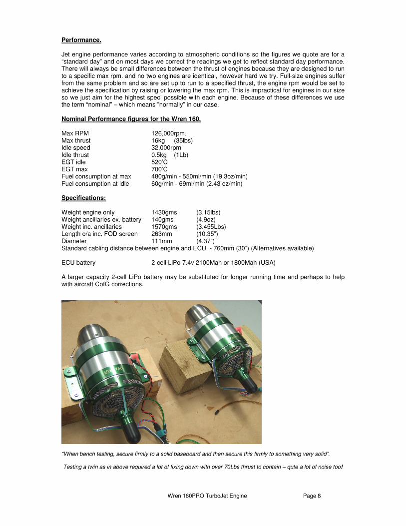
Performance. Jet engine performance varies according to atmospheric conditions so the figures we quote are for a “standard day” and on most days we correct the readings we get to reflect standard day performance. There will always be small differences between the thrust of engines because they are designed to run to a specific max rpm. and no two engines are identical, however hard we try. Full-size engines suffer from the same problem and so are set up to run to a specified thrust, the engine rpm would be set to achieve the specification by raising or lowering the max rpm. This is impractical for engines in our size so we just aim for the highest spec’ possible with each engine. Because of these differences we use the term “nominal” – which means ”normally” in our case. Nominal Performance figures for the Wren 160. Max RPM 126,000rpm. Max thrust 16kg (35lbs) Idle speed 32,000rpm Idle thrust 0.5kg (1Lb) EGT idle 520’C EGT max 700’C Fuel consumption at max 480g/min - 550ml/min (19.3oz/min) Fuel consumption at idle 60g/min - 69ml/min (2.43 oz/min) Specifications: Weight engine only 1430gms (3.15lbs) Weight ancillaries ex. battery 140gms (4.9oz) Weight inc. ancillaries 1570gms (3.455Lbs) Length o/a inc. FOD screen 263mm (10.35”) Diameter 111mm (4.37”) Standard cabling distance between engine and ECU - 760mm (30”) (Alternatives available) ECU battery 2-cell LiPo 7.4v 2100Mah or 1800Mah (USA) A larger capacity 2-cell LiPo battery may be substituted for longer running time and perhaps to help with aircraft CofG corrections.
“When bench testing, secure firmly to a solid baseboard and then secure this firmly to something very solid”. Testing a twin as in above required a lot of fixing down with over 70Lbs thrust to contain – qute a lot of noise too!
Wren 160PRO TurboJet Engine Page 9
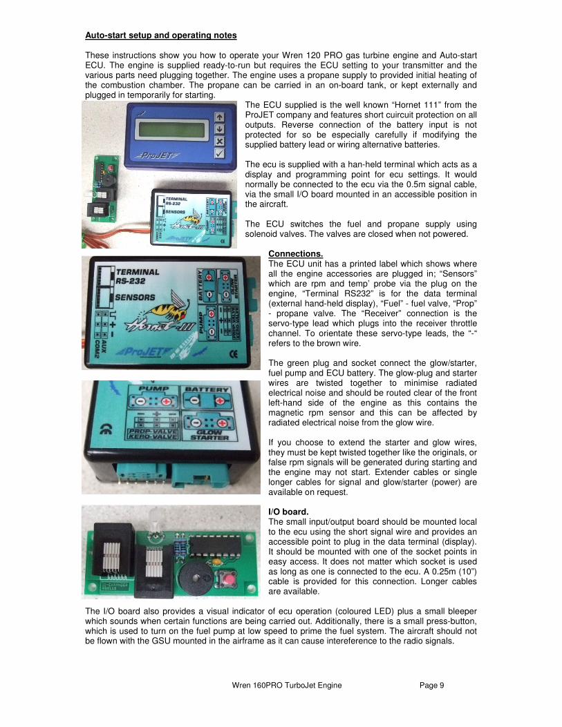
Auto-start setup and operating notes These instructions show you how to operate your Wren 120 PRO gas turbine engine and Auto-start ECU. The engine is supplied ready-to-run but requires the ECU setting to your transmitter and the various parts need plugging together. The engine uses a propane supply to provided initial heating of the combustion chamber. The propane can be carried in an on-board tank, or kept externally and plugged in temporarily for starting.
The ECU supplied is the well known “Hornet 111” from the ProJET company and features short cuircuit protection on all outputs. Reverse connection of the battery input is not protected for so be especially carefully if modifying the supplied battery lead or wiring alternative batteries. The ecu is supplied with a han-held terminal which acts as a display and programming point for ecu settings. It would normally be connected to the ecu via the 0.5m signal cable, via the small I/O board mounted in an accessible position in the aircraft. The ECU switches the fuel and propane supply using solenoid valves. The valves are closed when not powered.
Connections. The ECU unit has a printed label which shows where all the engine accessories are plugged in; “Sensors” which are rpm and temp’ probe via the plug on the engine, “Terminal RS232” is for the data terminal (external hand-held display), “Fuel” - fuel valve, “Prop” - propane valve. The “Receiver” connection is the servo-type lead which plugs into the receiver throttle channel. To orientate these servo-type leads, the “-“ refers to the brown wire. The green plug and socket connect the glow/starter, fuel pump and ECU battery. The glow-plug and starter wires are twisted together to minimise radiated electrical noise and should be routed clear of the front left-hand side of the engine as this contains the magnetic rpm sensor and this can be affected by radiated electrical noise from the glow wire. If you choose to extend the starter and glow wires, they must be kept twisted together like the originals, or false rpm signals will be generated during starting and the engine may not start. Extender cables or single longer cables for signal and glow/starter (power) are available on request. I/O board. The small input/output board should be mounted local to the ecu using the short signal wire and provides an accessible point to plug in the data terminal (display). It should be mounted with one of the socket points in easy access. It does not matter which socket is used as long as one is connected to the ecu. A 0.25m (10”) cable is provided for this connection. Longer cables are available.
The I/O board also provides a visual indicator of ecu operation (coloured LED) plus a small bleeper which sounds when certain functions are being carried out. Additionally, there is a small press-button, which is used to turn on the fuel pump at low speed to prime the fuel system. The aircraft should not be flown with the GSU mounted in the airframe as it can cause intereference to the radio signals.
Wren 160PRO TurboJet Engine Page 10
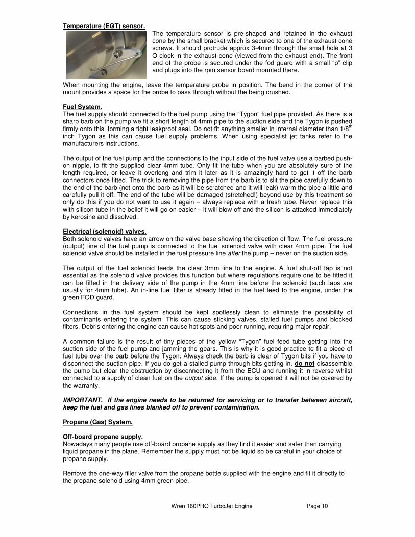
Temperature (EGT) sensor. The temperature sensor is pre-shaped and retained in the exhaust cone by the small bracket which is secured to one of the exhaust cone screws. It should protrude approx 3-4mm through the small hole at 3 O-clock in the exhaust cone (viewed from the exhaust end). The front end of the probe is secured under the fod guard with a small “p” clip and plugs into the rpm sensor board mounted there.
When mounting the engine, leave the temperature probe in position. The bend in the corner of the mount provides a space for the probe to pass through without the being crushed. Fuel System. The fuel supply should connected to the fuel pump using the “Tygon” fuel pipe provided. As there is a sharp barb on the pump we fit a short length of 4mm pipe to the suction side and the Tygon is pushed firmly onto this, forming a tight leakproof seal. Do not fit anything smaller in internal diameter than 1/8
th
inch Tygon as this can cause fuel supply problems. When using specialist jet tanks refer to the manufacturers instructions. The output of the fuel pump and the connections to the input side of the fuel valve use a barbed push-on nipple, to fit the supplied clear 4mm tube. Only fit the tube when you are absolutely sure of the length required, or leave it overlong and trim it later as it is amazingly hard to get it off the barb connectors once fitted. The trick to removing the pipe from the barb is to slit the pipe carefully down to the end of the barb (not onto the barb as it will be scratched and it will leak) warm the pipe a little and carefully pull it off. The end of the tube will be damaged (stretched!) beyond use by this treatment so only do this if you do not want to use it again – always replace with a fresh tube. Never replace this with silicon tube in the belief it will go on easier – it will blow off and the silicon is attacked immediately by kerosine and dissolved. Electrical (solenoid) valves. Both solenoid valves have an arrow on the valve base showing the direction of flow. The fuel pressure (output) line of the fuel pump is connected to the fuel solenoid valve with clear 4mm pipe. The fuel solenoid valve should be installed in the fuel pressure line after the pump – never on the suction side. The output of the fuel solenoid feeds the clear 3mm line to the engine. A fuel shut-off tap is not essential as the solenoid valve provides this function but where regulations require one to be fitted it can be fitted in the delivery side of the pump in the 4mm line before the solenoid (such taps are usually for 4mm tube). An in-line fuel filter is already fitted in the fuel feed to the engine, under the green FOD guard. Connections in the fuel system should be kept spotlessly clean to eliminate the possibility of contaminants entering the system. This can cause sticking valves, stalled fuel pumps and blocked filters. Debris entering the engine can cause hot spots and poor running, requiring major repair. A common failure is the result of tiny pieces of the yellow “Tygon” fuel feed tube getting into the suction side of the fuel pump and jamming the gears. This is why it is good practice to fit a piece of fuel tube over the barb before the Tygon. Always check the barb is clear of Tygon bits if you have to disconnect the suction pipe. If you do get a stalled pump through bits getting in, do not disassemble the pump but clear the obstruction by disconnecting it from the ECU and running it in reverse whilst connected to a supply of clean fuel on the output side. If the pump is opened it will not be covered by the warranty. IMPORTANT. If the engine needs to be returned for servicing or to transfer between aircraft, keep the fuel and gas lines blanked off to prevent contamination. Propane (Gas) System. Off-board propane supply. Nowadays many people use off-board propane supply as they find it easier and safer than carrying liquid propane in the plane. Remember the supply must not be liquid so be careful in your choice of propane supply. Remove the one-way filler valve from the propane bottle supplied with the engine and fit it directly to the propane solenoid using 4mm green pipe.
Wren 160PRO TurboJet Engine Page 11
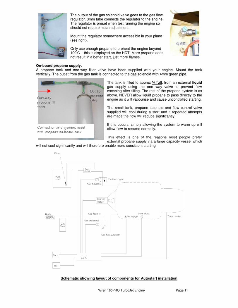
The output of the gas solenoid valve goes to the gas flow regulator. 3mm tube connects the regulator to the engine. The regulator is preset when test running the engine so should not require much adjustment. Mount the regulator somewhere accessible in your plane (see right). Only use enough propane to preheat the engine beyond 100’C – this is displayed on the HDT. More propane does not result in a better start, just more flames.
On-board propane supply. A propane tank and one-way filler valve have been supplied with your engine. Mount the tank vertically. The outlet from the gas tank is connected to the gas solenoid with 4mm green pipe.
The tank is filled to approx ¼ full, from an external liquid gas supply using the one way valve to prevent flow escaping after filling. The rest of the propane system is as above. NEVER allow liquid propane to pass directly to the engine as it will vapourise and cause uncontrolled starting. The small tank, propane solenoid and flow control valve supplied will cool during a start and if repeated attempts are made the flow will reduce significantly. If this occurs, simply allowing the system to warm up will allow flow to resume normally. This effect is one of the reasons most people prefer external propane supply via a large capacity vessel which
will not cool significantly and will therefore enable more consistent starting.
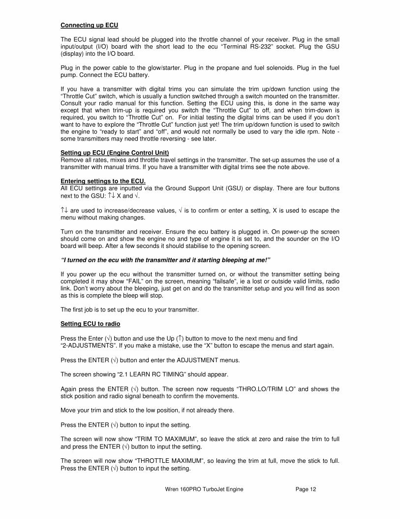
Schematic showing layout of components for Autostart installation
Fuel Solenoid
Gas feed in
Gas Solenoid
E.C.U
Fuelpump
Rx
Batt.
RPM pickup
Gas
Quick releasecoupling
Filter
Fueltank
Glow plug
Startermotor
Fuel to engine
Temp. probe
Tank
Gas flow adjuster
One-way propane fill valve
Out to propane valve
Connection arrangement used with propane on-board tank.
Wren 160PRO TurboJet Engine Page 12
Connecting up ECU The ECU signal lead should be plugged into the throttle channel of your receiver. Plug in the small input/output (I/O) board with the short lead to the ecu “Terminal RS-232” socket. Plug the GSU (display) into the I/O board. Plug in the power cable to the glow/starter. Plug in the propane and fuel solenoids. Plug in the fuel pump. Connect the ECU battery. If you have a transmitter with digital trims you can simulate the trim up/down function using the “Throttle Cut” switch, which is usually a function switched through a switch mounted on the transmitter. Consult your radio manual for this function. Setting the ECU using this, is done in the same way except that when trim-up is required you switch the “Throttle Cut” to off, and when trim-down is required, you switch to “Throttle Cut” on. For initial testing the digital trims can be used if you don’t want to have to explore the “Throttle Cut” function just yet! The trim up/down function is used to switch the engine to “ready to start” and “off”, and would not normally be used to vary the idle rpm. Note - some transmitters may need throttle reversing - see later. Setting up ECU (Engine Control Unit) Remove all rates, mixes and throttle travel settings in the transmitter. The set-up assumes the use of a transmitter with manual trims. If you have a transmitter with digital trims see the note above. Entering settings to the ECU. All ECU settings are inputted via the Ground Support Unit (GSU) or display. There are four buttons
next to the GSU: ↑↓ X and √.
↑↓ are used to increase/decrease values, √ is to confirm or enter a setting, X is used to escape the menu without making changes. Turn on the transmitter and receiver. Ensure the ecu battery is plugged in. On power-up the screen should come on and show the engine no and type of engine it is set to, and the sounder on the I/O board will beep. After a few seconds it should stabilise to the opening screen. “I turned on the ecu with the transmitter and it starting bleeping at me!” If you power up the ecu without the transmitter turned on, or without the transmitter setting being completed it may show “FAIL” on the screen, meaning “failsafe”, ie a lost or outside valid limits, radio link. Don’t worry about the bleeping, just get on and do the transmitter setup and you will find as soon as this is complete the bleep will stop. The first job is to set up the ecu to your transmitter. Setting ECU to radio
Press the Enter (√) button and use the Up (↑) button to move to the next menu and find “2-ADJUSTMENTS”. If you make a mistake, use the “X” button to escape the menus and start again.
Press the ENTER (√) button and enter the ADJUSTMENT menus. The screen showing “2.1 LEARN RC TIMING” should appear.
Again press the ENTER (√) button. The screen now requests “THRO.LO/TRIM LO” and shows the stick position and radio signal beneath to confirm the movements. Move your trim and stick to the low position, if not already there.
Press the ENTER (√) button to input the setting. The screen will now show “TRIM TO MAXIMUM”, so leave the stick at zero and raise the trim to full
and press the ENTER (√) button to input the setting. The screen will now show “THROTTLE MAXIMUM”, so leaving the trim at full, move the stick to full.
Press the ENTER (√) button to input the setting.

Wren 160PRO TurboJet Engine Page 13
If you then see a screen showing !!!ADJUSTMENT FAULTY!!! then either the transmitter was not turned on or you need to reverse the throttle sense (common on Futaba transmitters). If the setup was done correctly the screen will revert to “2.1 LEARN RC TIMING” and you have been successful. This completes your radio set-up. It should only need doing again if the radio settings are changed or installation moved to another radio. Filling the On-board propane tank. The propane required is from a propane gas canister available from hardware stores (screw-top variety) and will ideally be 30% propane 70% butane, the higher propane mix means less is needed and quicker (hotter) starting. Other suitable types are those sold for the “Taymar” and similar blowtorches but check carefully the propane content. Ensure all the pipework to the engine is complete before attempting to fill the gas tank. Do your propane filling outside in open air away from sources of ignition, no smoking etc. Connect the gas canister to the one-way valve and invert the cylinder so the valve is at the bottom, and open the valve. Liquid gas will be seen to travel down the tube to the tank. Disconnect the tank when the flow ceases. The tank does not need to be any more than about 1/3
rd full for several successful starts. Do
not attempt to fill more than this as it is unnecessary and will not aid gas supply. To confirm all is connected correctly, check the operation of the starter and propane system. This can only be done once the engine is properly installed and plumbing completed. Testing should be done outside in the open air away from flammables as we are generating a flame here. Turn off the receiver, wait a few seconds and then turn back on again (this is how you reset the ECU). The screwdown valve is preset to 2-1/2 to 3-1/2 out, so leave it there for the test. With the throttle stick down, raise your trim to full-up and confirm the display changes from “–OFF to 0%”. If you are using an external propane supply (off-board gas-only supply), connect the supply and open the propane tap. Trial starting. Raise the throttle stick to full. Then lower the stick to off and within two seconds raise it back to full again. You will hear a little bleep from the small I/O board to indicate the process. This is the signal for the ECU to start the engine. Don’t worry that the engine will rev up to max, it will not, it will only go for a start. The starter will kick in and spin the engine up, the gas valve will open and the gas should light with a gentle “plop”. When this happens the temperature on the ECU display should be seen to rise fairly quickly and the starter will start to accelerate the engine. As soon as you see/hear this, lower the stick and trim trim back to zero to terminate the start sequence. The ECU will then spin the engine back up without the gas on to clear the engine (showing “cooling” on the display. If the gas does not light easily adjust the screw-down valve setting. You will quickly find a setting that works best. Less gas rather than more usually works best but you will need to experiment. Remember you are not adding any lubricant to the engine by spinning it up on gas so don’t do this more that a few times or the bearings will dry out. After each trial to do a second start you simply need to return the trim to off and then back up to enable a subsequent start using the throttle stick. If the gas does not turn on and the display shows only “COOLING” it usually because the battery is
becoming discharged and the voltage has dropped too low. To check this, use the UP button (↑) and move to the screen showing the battery symbol and the voltage. Once you have this, initiate a start in the normal way and watch the voltage. If it drops below 6V (setting for 2-cell LiPo’s) then it is discharged and needs recharging. The ecu will not allow a start to go ahead if the battery is insufficient to complete a run.

Wren 160PRO TurboJet Engine Page 14
Failsafe function. The ecu checks the incoming throttle channel pulses from the receiver to ensure they are between the limits set when the transmitter setup was carried out. If a signal arrives outside this range or is corrupted the failsafe function is enabled. The failsafe function will stop the engine in the event of loss of radio link or continued radio interference that masks the normal signal, but will allow the engine to continue to operate in the case of short glitches. The system works with PCM, PPM and IPD systems. VERY IMPORTANT - The radio must be set to shut the engine off in event of loss of valid signal. If the receiver is set to “hold” the failsafe in the ecu will not be able to work. Operation is as follows: The ecu will tolerate loss or corrupted radio signal for up to 0.5 sec’s. If loss or corrupted signal continues beyond 0.5 seconds the ecu will command the engine to go to 10% thrust. If the error condition continues for a further 1.5 seconds the ecu will shut the engine off. This system allows the engine to fly through minor interruptions of signal or glitches, thus avoiding the engine shutting off unnecessarily, while maintaining the safety of automatic shutdown in cases of loss or corruption of radio link.
IMPORTANT - ALWAYS PROGRAMME THE RECEIVER FAILSAFE TO SHUT OFF THE ENGINE. NEVER FLY A TURBINE AIRCRAFT WITH THE FAILSAFE SET TO “HOLD”.
Andy Johnsons Wren 160 powered “Flash” – fantastic combination!
Wren 160PRO TurboJet Engine Page 15
Running the engine. Once you have done a few practice gas light-ups you can connect up your fuel tank and prepare for a proper engine run. Secure your test stand or aircraft firmly. Position it in a suitable place in a well ventilated area, preferably outside and clear of any likely hazards. Refill the propane tank if it is getting low. Check all leads and pipes are in the correct position and properly connected. Ensure your fire extinguisher is in position and you are ready. Priming the fuel system - new installation. When the fuel system is first installed the fuel lines will be empty. To prime the lines up to the engine, connect the ecu battery and turn on the radio. When the screen has settled, press the small button on the small I/O board and the pump will turn on at low speed and the fuel solenoid will open. Watch for the fuel travelling up the line to the engine and release the button when it reaches the engine. Do not continue the prime beyond this point as the engine may be flooded with excess fuel. Once the lines are fuelled there is no need to repeat the priming process again. Check the danger area is clear of onlookers before making an engine start. The small led on the I/O board will change from green to orange when you raise the trim and stick to full , indicating it is ready for a start. Initiate the start in the normal way (lower stick to zero and then back up to full). As soon as the gas has lit and the starter is starting to accelerate the engine you should see fuel travelling up the clear fuel line to the engine. If the fuel line was empty the start may terminate. In this case simply lower the trim and then try again. If it does the same again, restart but increase the gas supply slightly. As soon as the engine is spinning up and fuel has arrived in the engine the note will change and a small flame may appear from the exhaust but this is normal. The engine should accelerate up past 20,000rpm where you will hear the starter dis-engage, the engine should continue to accelerate up to idle at 32,000rpm. During starting the green led on the ECU will blink to show the fuel pump is speeding up and “fuelramp” will show on the display. When the engine has reached idle and stabilised the led will change to red. Do not touch the throttle stick while the start is under way as the ECU will terminate the start sequence. If you want to terminate the start sequence, simply lower the stick and trim to zero and the start will cease. The engine will stop hot however and it will automatically go into cooling mode and cool the engine to 80’C. Calibration. When the engine has reached idle it will pause for a few seconds and then continue accellerating up to the “calibration” rpm (set to 65,000rpm). It needs to do this every time the engine is started to allow the ecu to verify the fuel pump voltage requirements. While this accelleration is proceeding you can lower the stick to idle and wait for the calibration to complete. You will not have stick control until calibration has completed. You will hear the engine rev up to the calibration point and then once this is reached it will return to idle and you will then have control of the engine and the engine should respond to stick movements by increasing and decreasing the rpms. Whilst the engine is idling the rpm may initially be slightly unstable initially but this will settle out in a few seconds. Throttle response. Once the engine is back at idle you can operate the throttle stick. Over a period of about five seconds, raise the throttle to full and the rpm should increase to close to 126,000rpm. Lower the throttle back to idle and the engine should run back to idle. The ECU needs this cycle to learn the throttle stick position to rpm match and it is good practice to do this at the beginning of all engine runs. You can now explore the response time of the engine. Note the stick position relates directly to the engine thrust, 1/2 stick = 1/2 thrust, 3/4 stick = ¾ thrust and so on. If you find you need a more gentle response, if you enter the first SETUP menu, there is a setting for throttle response; fast, medium and slow. The default is FAST. Shutting down. When you are ready to shut down, throttle to around 40,000rpm for about five seconds and lower stick and trim to zero to stop the engine. As the engine comes to a stop the starter will kick in to spin the engine gently for the cool-down cycle until the engine has cooled to 80’C. Wait until the cooldown is completed. The receiver and transmitter can now be turned off. If this is the last run for a while or the day, disconnect the ecu battery.

Wren 160PRO TurboJet Engine Page 16
Care and Maintenance The engine, like most mechanical machines will appreciate being kept clean and dry. Keep the intake clear from ingress of grass, fluff and all the other small bits the engine will “find” from around itself while running. The engine has no consumable parts in the accepted sense of the word, however the rotor bearings will eventually wear and become noisy. We recommend a service interval of 50 hrs. Be careful to ensure your ECU battery is kept well charged in order that the engine is always started briskly and properly cooled down after a run. After flying is completed, disconnect the ECU battery from the ECU. Failing to do this will cause the battery to discharge beyond the level to which it can be recovered. If this occurs the only option is a replacement battery. Warranty will not cover a deep discharged battery. General check-points: Ensure that the ECU battery has sufficient charge before flying. Note the amount of charge required after a flight/run to recharge the battery and take this away from the battery capacity. Example if a previously fully charged battery requires 650ma to recharge and battery capacity = 2100mAh, 2100-650 = 1450. This would indicate it should be safe to make a second flight but then the battery would require recharging. Always aim to leave at least 500mAh reserve. If in doubt, charge before each flight. LiPo’s do not mind this and it will not harm their capacity. If don’t want to charge at the flying field then fit a larger capacity battery or get a second battery which you can swap in after flight(s). Keep the rpm pickup clear of stray magnetic sources such as fuel pump, solenoid valves, glow plug wire, or servos, as the magnetic field generated can upset the rpm reading. Note, the glow and starter wires are deliberately twisted tightly together to minimise stray interference. Do not straighten them out in the belief this will “neaten” your installation. If you replace the glow plug, the last two turns of the element must be pulled out by about 1.5mm to ensure prompt gas ignition. Do not fly with the display unit attached to the ECU as this is a potential source of interference. You must set-up the ECU with your radio before it will operate correctly, so do this first. Note - to
confirm and enter each setting you need to press the “ENTER” (√) button on the display. Propane/Butane gas mixtures work well in temperate climates. Beware of using too much gas in the belief this will ignite more easily. 100 % Propane can be used instead, but the pressure is very much higher and more care should be taken. We recommend you set-up and confirm the operation of your Auto-start installation on the test-stand, before installing into your model. This is particularly important if this is your first turbine. The ecu is pre-programmed to suit all Wren 160 engines. The settings have been found suitable for most Wren 160 installations. The only adjustment to running you may wish to employ is to change the acceleration/decelleration rate to allow for hot conditions where the acceleration may not be as smooth as before. This setting is held in the no.1 (SETUP) menu. Enter this and proceed to 1.3 ACC/DEC TIMING. This is normally set to FAST. You can change to MEDIUM or SLOW. Each setting is 10% slower than the previous setting. This should solve the problem. Remember the engine has already been run and the ECU adjusted to optimum conditions with the fuel pump supplied – it should therefore only require setting to your radio and it should then run perfectly. Please do this before making any adjustments as in our experience unnecessary adjustment of the ECU settings will only add problems to an otherwise perfect set-up. Exhaust temp. At all times the temp should remain well below the value set in the main menu (usually 800’C). If the engine goes over this value the ECU will reduce the fuel pump power until the overheat has passed. It is quite normal to have very short term high temp spikes of a couple of seconds, but longer than this can result in overheating of the engine and the ECU may shut the engine down, and the cause should be investigated.

Wren 160PRO TurboJet Engine Page 17
Starter propane. Problems lighting the propane are mostly related to plug element exposure, ensure the element is pulled clear so the gas can really “see” the element. It needs to glow bright yellow for good ignition, so adjust the “glow power” setting in the main menu as required. Note – only change the setting when you have fitted a fresh charged battery or you may accidentally overpower it. Propane supply must be gas vapour – not liquid. Propane/Butane mixtures work best in all climates. Normally less propane is the secret - too much will be harder to light and tends to flame out of the exhaust when it finally does ignite. GlowPlug power setting. The power setting for the glowplup is normally set to 1.4V and is contained in the 2-ADJUSTMENTS menu. If the plug is replaced with a similar plug the setting will probably be ok but if changed for a different type the setting may need to be altered. Always set lower for a nother plug and increase to achieve the power needed for a yellow glow. Do not overpower the plug in the belief it will help starting. To see or change the glow power setting, enter 2-ADJUSTMENTS menu and proceed to 2.2
“ADJUSTMENT GLOW PLUG”. To change the setting use the ↑↓ buttons to increase/decrease power
as required. Once happy with the setting press the ENTER (√) button to store the new value.
Wren 160PRO TurboJet Engine Page 18
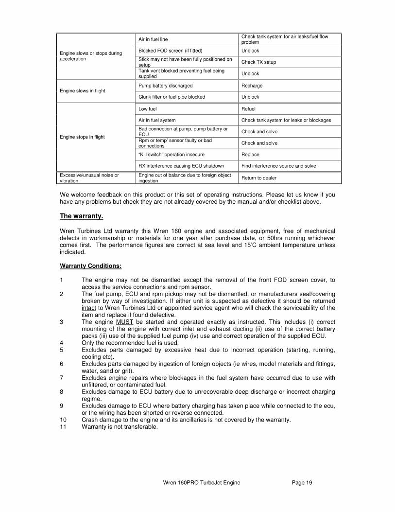
Problems Checklist. If something does not quite work how it should, work through the following checklist to isolate the fault and provide a cure or the appropriate action as required:
Symptom Problem Action
RX not switched on or RX battery discharged
Verify connection and charge if necessary
Display not connected properly Ensure that display is connected and that the plug ‘clicks’ into place
Display malfunction Contact Wren
No reading on ECU display unit (ecu battery should be plugged in)
ECU problem Contact Wren
Thermocouple not connected to ECU
Verify connection
ECU problem Contact Wren
Temp’’ reading incorrect or “0”
Thermocouple failure Contact Wren
Rpm sensor plug inserted incorrectly
Ensure connector fully inserted into the ECU
Rpm sensor lead broken/chafed Contact Wren and remove source of chafing
Rpm sensor malfunction Contact Wren
No rpm indicated when engine is spun
ECU problem Contact Wren
Propane bottle empty/low/ very cold Check flow by sound/smell, replace or warm as necessary
Poor glow at plug Check battery voltage
Plug blown Replace plug
ECU battery low Charge
Glow element not exposed Tease out with pin
Propane will not ignite
Glow power insufficient Increase by Glow Power slightly
SymptomSymptomSymptomSymptom ProblemProblemProblemProblem ActionActionActionAction
Pump not connected Check wiring
See “Starting the engine” Fuel pump not running
Pump jammed with foreign object Investigate operation
Insufficient gas supply Increase flow/renew can No or little temp’ rise on propane lit Temp’ probe not inserted into
exhaust cone Insert 3mm
Fuel not reaching tank pick-up Check clunk for blockage. Ensure fuel like is not kinked
Pump fault Contact Dealer Pump runs but no fuel delivered
Fuel solenoid not opening Check wiring to ECU
Insufficient revs on starter motor Recharge ECU battery Clutch slipping Replace O-ring No or little rpm increase
as fuel enters Air in fuel line
Air will disappear after several seconds
Trim down/shut off fuel & gas immediately
Residual fuel in engine Remove fuel solenoid plug and start “dry” for 10 seconds to clear
There was air in fuel system Restart
Insufficient revs on starter Recharge ECU battery
Starter motor burnt out/inoperative Dealer replacement ECU settings changed from defaults Return to defaults
Excessive flaming
Engine malfunction Return to dealer
Normal problem until ECU settles down Engine overshoots at idle Air in fuel line causes late but rapid start-up ECU will correct itself and settle down
“Overtemp’” is detected by ECU and shutdown if temp’ has run over 800’C due to long hot start, low start battery or air in fuel line.
Cool off and restart Engine slows or is stopped during start
Wild rpm reading Interference to rpm pickup by electromagnetic device sited too close, find and move.
Wren 160PRO TurboJet Engine Page 19
We welcome feedback on this product or this set of operating instructions. Please let us know if you have any problems but check they are not already covered by the manual and/or checklist above.
The warranty. Wren Turbines Ltd warranty this Wren 160 engine and associated equipment, free of mechanical defects in workmanship or materials for one year after purchase date, or 50hrs running whichever comes first. The performance figures are correct at sea level and 15’C ambient temperature unless indicated. Warranty Conditions: 1 The engine may not be dismantled except the removal of the front FOD screen cover, to
access the service connections and rpm sensor. 2 The fuel pump, ECU and rpm pickup may not be dismantled, or manufacturers seal/covering
broken by way of investigation. If either unit is suspected as defective it should be returned intact to Wren Turbines Ltd or appointed service agent who will check the serviceability of the item and replace if found defective.
3 The engine MUST be started and operated exactly as instructed. This includes (i) correct mounting of the engine with correct inlet and exhaust ducting (ii) use of the correct battery packs (iii) use of the supplied fuel pump (iv) use and correct operation of the supplied ECU.
4 Only the recommended fuel is used. 5 Excludes parts damaged by excessive heat due to incorrect operation (starting, running,
cooling etc). 6 Excludes parts damaged by ingestion of foreign objects (ie wires, model materials and fittings,
water, sand or grit). 7 Excludes engine repairs where blockages in the fuel system have occurred due to use with
unfiltered, or contaminated fuel. 8 Excludes damage to ECU battery due to unrecoverable deep discharge or incorrect charging
regime. 9 Excludes damage to ECU where battery charging has taken place while connected to the ecu,
or the wiring has been shorted or reverse connected. 10 Crash damage to the engine and its ancillaries is not covered by the warranty. 11 Warranty is not transferable.
Air in fuel line Check tank system for air leaks/fuel flow problem
Blocked FOD screen (if fitted) Unblock
Stick may not have been fully positioned on setup
Check TX setup
Engine slows or stops during acceleration
Tank vent blocked preventing fuel being supplied
Unblock
Pump battery discharged Recharge Engine slows in flight
Clunk filter or fuel pipe blocked Unblock
Low fuel Refuel
Air in fuel system Check tank system for leaks or blockages
Bad connection at pump, pump battery or ECU
Check and solve
Rpm or temp’ sensor faulty or bad connections
Check and solve
“Kill switch” operation insecure Replace
Engine stops in flight
RX interference causing ECU shutdown Find interference source and solve
Excessive/unusual noise or vibration
Engine out of balance due to foreign object ingestion
Return to dealer
Wren 160PRO TurboJet Engine Page 20
Repair. Damage or defective operation covered under the warranty terms will be repaired and tested at no cost to the original owner (other than post and packing). Repairs not covered under the terms of the warranty will be carried out by Wren Turbines Ltd, or their appointed agents, after agreement of costs. Before returning the engine or ancillary equipment for service or repair, please contact Wren Turbines Ltd or Wren Turbines USA in the USA, to agree action and costs. In the USA: Wren Turbines USA 1027 Southampton Drive Decatur Indiana 46733 Ron Ballard. Telephone: 260-724-8936 Cell: 260-701-8936 Website: http://www.wrenturbinesusa.com email: [email protected] Rest of World: Wren Turbines Ltd Unit 19, Century Park Network Centre Manvers Rotherham S63 5DE UK Tel +44 1709 877439 Fax +44 1709 875935 www.wrenturbines.co.uk email [email protected]