wind energy - aerodynamicsesc.fsu.edu/documents/lectures/fall2006/eml4450l21.pdf · sustainable...
TRANSCRIPT

Sustainable Energy Science and Engineering Center
Wind Energy - Aerodynamics

Sustainable Energy Science and Engineering Center
One dimensional momentum theory
Assumptions:
Incompressible, inviscid, steady state flow
Infinite number of blades
Uniform thrust over the rotor area
Non rotating wake
The thrust T (equal and opposite to the force of the wind on the wind turbine) is given by
Source: Wind Energy Explained by J.F Manwell, J.G. McGowan and A.L. Rogers, John Wiley, 2002.
Wind Turbine Aerodynamics
T =
T = U1 ρUA( )1−U4 ρUA( )4
Ý m = ρUA( )1 = ρUA( )4
T = Ý m U1 −U4( )= A2 p2 − p3( )
p1 +12
ρU12 = p2 +
12
ρU22
p3 + 12
ρU32 = p4 + 1
2ρU4
2

Sustainable Energy Science and Engineering Center
One dimensional momentum theory
Using the Bernoulli equation on either side of the rotor and assuming p1 = p4
Where a is the axial induction factor and U1a is referred to as the induced velocity at the rotor. The power output, P is given by
T =12
ρA2 U12 −U4
2( )
U2 =U1 + U4
2
a =U1 −U2
U1
P =12
ρA2 U12 −U4
2( )U2
PPo
= Cp =P
12
ρU 3A
Cpmax imum= 0.5926
(1-a)U1 (1-2a)U1
P =12
ρAU 3 4a(1− a)2
U1 = U;A2 = A
Cp =P
12
ρAU 3= 4a(1− a)2
dCp
da= 0 ⇒ a =
13
Cpmax=
1627
= 0.5926
a < 0.5
Betz Limit

Sustainable Energy Science and Engineering Center
Betz Limit
(2/3) U1 (1/3) U1
Maximum power production:
The axial thrust on the disk at maximum power:
T =12
ρAU12 4a 1− a( )[ ]
CT =T
12
ρAU 2=
89
Overall efficiency: ηoverall =Pout
12
ρAU 3= ηmechCP
Pout =12
ρAU 3(ηmechCP )

Sustainable Energy Science and Engineering Center
Ideal wind turbine with wake rotation
Angular velocity of the rotor : Ω
Angular velocity imparted to the flow stream: ω
Angular induction factor: a` = ω/2Ω
Blade tip speed : λ = ΩR/U
Local Speed ratio: λr = λr/R
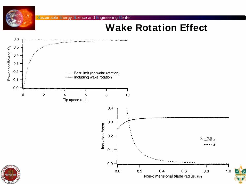
Wake Rotation
When deriving the Betz limit, it was assumed that no rotation was imparted to the flow. Rotating rotor generates angular momentum, which can be related to rotor torque. The flow behind the rotor rotates in the opposite direction to the rotor, in reaction to the torque exerted by the flow on the rotor.

Sustainable Energy Science and Engineering Center
Ω
Ω+ω
p2 − p3 = ρ Ω +12
ω⎛ ⎝ ⎜
⎞ ⎠ ⎟ ωr2
dT = p2 − p3( )dA = ρ Ω +12
ω⎛ ⎝ ⎜
⎞ ⎠ ⎟ ωr2 2πrdr( )
′ a =ω2Ω
angular Induction factor
The induced velocity at the rotor consists of not only the axial component Ua but also a component in the rotor plane rΩa`
Loss of Energy Due to Wake Rotation

Sustainable Energy Science and Engineering Center
dT = 4 ′ a (1+ ′ a ) 12
ρΩ2r22πrdr
Thrust on an annular cross section due to linear momentum:
dT = 4a(1+ a) 12
ρU 22πrdr
Equating the two expressions for thrust gives:
a(1− a)′ a (1+ ′ a )
=Ω2r2
U 2 = λr2
Where λr is the local speed ratio. The tip speed ratio λ defined as the ratio of the blade tip speed to the free stream wind speed is given by
λ =ΩrU
= λrRr
Loss of Energy Due to Wake Rotation

Sustainable Energy Science and Engineering Center
Loss of Energy Due to Wake RotationTorque exerted on the rotor: Q = change in the angular momentum of the wake
The power generated at each element becomes:
The axial angular induction factors determine the magnitude and direction of the airflow at the rotor plane.
The incremental contribution to the power coefficient, dCp from each annular ring is given by:
dQ = d Ý m ωr( )r = ρU22πrdr( )r⎡ ⎤
dP = ΩdQ =12
ρAU 3 8λ2 ′ a 1− a( )λr
3dλr
⎡ ⎣ ⎢
⎤ ⎦ ⎥
dCp =dP
12
ρAU 2
Cp = 8λ2 ′ a (1− a)λr
3
0
λ
∫ dλr
Sustainable Energy Science and Engineering Center
λ = 7.5
Wake Rotation Effect
Sustainable Energy Science and Engineering Center
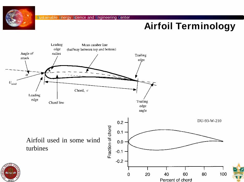
Airfoil Terminology
DU-93-W-210
Airfoil used in some wind turbines

Sustainable Energy Science and Engineering Center
Forces on Airfoil
Important parameter: Reynolds number = UL/ν = 0.5 − 10 x 106
Lift coefficient, l: span of the airfoil
Drag Coefficient
Pitching moment Coefficient, A = lc
Cl =L
l12
ρU 2c
CD =D
l12
ρU 2c
Cm =M
12
ρU 2Ac

Sustainable Energy Science and Engineering Center
Airfoil characteristics
Cl = 2πα
CD=Cdo+(Cl2/πeAR)

Sustainable Energy Science and Engineering Center
DU-93-W-210
DU-93-W-210
S809 airfoil
Aerodynamic Coefficients

Sustainable Energy Science and Engineering Center
Stall Characteristics of Turbine Blade
α=30ºt=261 ms
α=25ºt=217 ms
α=20ºt=174 ms
Sustainable Energy Science and Engineering Center
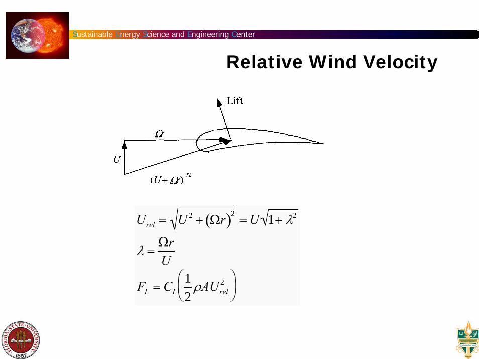
Relative Wind Velocity
Urel = U 2 + Ωr( )2 = U 1+ λ2
λ =ΩrU
FL = CL12
ρAUrel2⎛
⎝ ⎜
⎞ ⎠ ⎟

Sustainable Energy Science and Engineering Center
Burton et al. (2001)
0.0
0.5
1.0
1.5
2.0
2.5
3.0
0.0 20.0 40.0 60.0LFA (deg)
Cn
PARKED, 20 m/sPARKED, 30 m/sROTATING
Source: Pat Moriarty, NREL
Rotation Effect on Cn

Sustainable Energy Science and Engineering Center
Assumptions: no aerodynamic interaction between elements and the forces on the blades are determined solely by the lift and drag characteristics of the airfoil shape of the blade
Wind velocity at the rotor =U(1-a)+(Ωr+ωr/2)
blade section velocity induced angular velocity
Blade Element Theory

Sustainable Energy Science and Engineering Center
If the rotor has n blades, the total normal force on the section at a distance r, from the center is
The differential torque due to tangential force operating at a distance r, from the center is given by
Urel =U 1− a( )
sinφ
dFL = Cl12
ρUrel2 cdr
dFD = Cd12
ρUrel2 cdr
dFN = dFL cosφ + dFD sinφdFT = dFL sinφ − dFD cosφ
dFN = n 12
ρUrel2 Cl cosφ + Cd sinφ( )cdr
dQ = nrdFT = n 12
ρUrel2 Cl sinφ − Cd cosφ( )crdr
Blade Element Theory

Sustainable Energy Science and Engineering Center
The relative velocity can be expressed as a function of free stream velocity and the resulting equations for normal force or thrust and torque can be written as
Where σ` is the local solidity, defined by
dFN = ′ σ πρU 2 1− a( )2
sin2 φCl cosφ + Cd sinφ( )rdr
dQ = ′ σ πρU 2 1− a( )2
sin2 φCl sinφ − Cd cosφ( )r2dr
′ σ =nc
2πr
Blade Element Theory

Sustainable Energy Science and Engineering Center
Blade Element Theory
If we set Cd =0 - a reasonable assumption that simplifies the analysis and introduces negligible errors, we obtain
Cl = 4 sinφcosφ − λr sinφ( )′ σ sinφ + λr cosφ( )
a′ a =
λr
tanφ
a = 1
1+4sin2 φ′ σ Cl cosφ
⎡
⎣ ⎢
⎤
⎦ ⎥
′ a =1
4 cosφ′ σ Cl
−1⎡
⎣ ⎢
⎤
⎦ ⎥

Sustainable Energy Science and Engineering Center
Optimum Performance
Losses are due to tip speed ratio, airfoil drag and tip losses (a function of number of blades).
The maximum achievable power coefficient for turbines with an optimum blade shape with finite number of blades and aerodynamic drag is given by an empirical formula developed from experimental data as follows:
Cpmax=
1627
λ λ +1.32 +
λ − 820
⎛ ⎝ ⎜
⎞ ⎠ ⎟
n23
2⎡
⎣
⎢ ⎢ ⎢ ⎢
⎤
⎦
⎥ ⎥ ⎥ ⎥
−1
−0.57λ2
Cl
Cd
λ +1
2n⎛ ⎝ ⎜
⎞ ⎠ ⎟
Cl
Cd
= 25 − ∞
n =1− 3λ = 4 − 20
for

Sustainable Energy Science and Engineering Center
Optimal Performance

Sustainable Energy Science and Engineering Center
OrientationOrientation: Horizontal axis wind turbines or vertical axis wind turbines
The basic theoretical advantages of a vertical axis machine are:- You may place the generator, gearbox etc. on the ground, and you may not need a tower for the machine. - You do not need a yaw mechanism to turn the rotor against the wind. The basic disadvantages are: - Wind speeds are very low close to ground level, so although youmay save a tower, your wind speeds will be very low on the lowerpart of your rotor. - The overall efficiency of the vertical axis machines is not impressive. - The machine is not self-starting (This is only a minor inconvenience for a grid connected turbine, however, since you may use the generator as a motor drawing current from the grid to to start the machine). - The machine may need guy wires to hold it up, but guy wires areimpractical in heavily farmed areas.

Sustainable Energy Science and Engineering Center
Orientation: Upwind or downwind machines
Upwind: rotor facing the wind - most wind turbines have this design
Needs a yaw mechanism to keep the rotor facing the wind.
Downwind machine: rotor placed on the lee side of the machine and is built without a yaw mechanism. Rotor passes through wind shade of the tower giving raise to fluctuation in the wind.
Orientation

Sustainable Energy Science and Engineering Center
Number of Blades
Three bladed concept: better stability properties
Two bladed concept: cost & weight; higher rotational speed to yield the same energy output
one bladed concept

Sustainable Energy Science and Engineering Center
Wind Turbine Components
1. Rotor blades
2. The hub - attached to the low speed shaft of the turbine
3. Gear box (1-50)
4. Electrical generator
5. Hydraulic system
6. Low speed shaft (20~30 rpm)
7. High speed shaft (~1500 rpm)
8. Yaw mechanism
9. Electronic controller
10. Anemometer
11. Cooling unit

Sustainable Energy Science and Engineering Center
NoiseNoise: Mechanical noise and aerodynamic noise
Mechanical noise: metal components moving (e.g.: gear box), better engineering practices will mitigate this problem by avoiding resonance phenomena and sound insulation.
1Aerodynamic noise: Sound pressure levels will increase with fifth power of the blade speed relative to the surrounding air. The major sources of the noise are: trailing edge, blade tip and unsteady separation on the blade
Minimum distance: 7 rotor diameters

Sustainable Energy Science and Engineering Center
Environment
Environment: Landscape and turbines
Aesthetically pleasing layout
Simple geometrical pattern: turbines placed equidistantly in a straight line

Sustainable Energy Science and Engineering Center
BirdsBirds often collide with high voltage overhead lines, masts, poles, and windows of buildings. They are also killed by cars in the traffic. Birds are seldom bothered by wind turbines, however. Radar studies from Tjaereborg in the western part of Denmark, where a 2 megawatt wind turbine with 60 m rotor diameter is installed, show that birds - by day or night - tend to change their flight route some 100-200 m before the turbine and pass above the turbine at a safe distance. In Denmark there are several examples of birds (falcons) nesting in cages mounted on wind turbine towers. The only known site with bird collision problems is located in the Altamont Pass in California. Even there, collisions are not common, but they are of extra concern because the species involved are protected by law. A study from the Danish Ministry of the Environment says that power lines, including power lines leading to wind farms, are a much greater danger to birds than the wind turbines themselves. Some birds get accustomed to wind turbines very quickly, others take a somewhat longer time. The possibilities of erecting wind farms next to bird sanctuaries therefore depend on the species in question. Migratory routes of birds will usually be taken into account when sitting wind farms, although bird studies from Yukon, Canada, show that migratory birds do not collide with wind turbines (Canadian Wind Energy Association Conference, 1997).

Sustainable Energy Science and Engineering Center
8 11
According to Leslie Evans Ogden, “The U.S. Fish and Wildlife Services (FWS) estimates that at least 4 million to 5 million birds are killed annually in communication tower collisions in the United States…Add this to the estimated 98 million birds killed annually by collisions with glass windows, especially those of tall office buildings, and it becomes clear that tall structures pose a very real threat to bird populations.
Birds and Wind Turbines
On the other hand, a comprehensive review of communication tower kill literature published between 1995 and March 2000, commissioned by the U.S. FWS (which includes a section on wind turbine collisions), revealed that less than 100 avian fatalities involving wind turbines in the U.S. have been reported in that time period (excepting the installation at Altamont Pass). The highly publicized bird kills at Altamont Pass in California are the only significant (large number) kills involving wind turbines reported at any installation to date.
Birds

Sustainable Energy Science and Engineering Center
Birds
Wind farms pose low risk to birds*
Migrating birds are unlikely to be seriously affected by offshore wind farms, according to a study.
Scientists found that birds simply fly around the farm, or between the turbines; less than 1% are in danger of colliding with the giant structures.
The research project involved one of Denmark's two large offshore wind farms, Nysted in the Baltic Sea, which contains 72 turbines each measuring 69m to the top of the nacelle or hub. It started operating in 2003.
* BBC NEWS:http://news.bbc.co.uk/go/pr/fr/-/2/hi/science/nature/4072756.stmPublished: 2005/06/08 10:13:42 GMT

Sustainable Energy Science and Engineering Center
Economics
Economies of Scale As you move from a 150 kW machine to a 600 kW machine, prices will roughly triple, rather than quadruple. The reason is, that there are economies of scale up to a certain point, e.g. the amount of manpower involved in building a 150 kW machine is not very different from what is required to build a 600 kW machine. E.g. the safety features, and the amount of electronics required to run a small or a large machine is roughly the same. There may also be (some) economies of scale in operating wind parks rater than individual turbines, although such economies tend to be rather limited.

Sustainable Energy Science and Engineering Center
Off shore costs:
$1.7M/1Mw
Economics
Sustainable Energy Science and Engineering Center
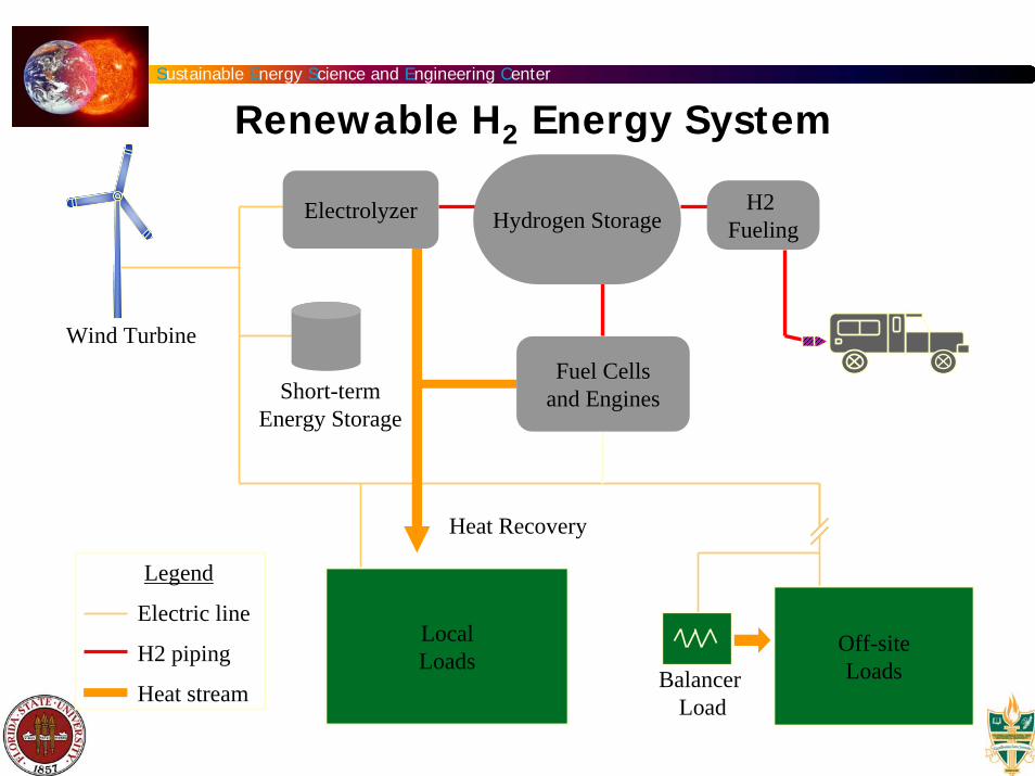
Wind Turbine
Short-term Energy Storage
BalancerLoad
Heat Recovery
Electric line
H2 piping
Heat stream
Legend
Off-siteLoads
Hydrogen StorageH2
FuelingElectrolyzer
LocalLoads
Fuel Cells and Engines
Renewable H2 Energy System