wellington inner city bypass: integrated design of trench ...€¦ · the soil nailed walls...
TRANSCRIPT

Wellington Inner City Bypass: Integrated Design of Trench Section Brabhaharan
1
Wellington Inner City Bypass: Integrated Design of Trench Section for Whole of Life Performance
P Brabhaharan, Principal, Geotechnical Engineering & Risk,
& K Atkinson, Principal Projects Engineer, Opus International Consultants
SYNOPSIS The Wellington Inner City Bypass is a lifeline urban arterial road that incorporates a trench structure depressed up to 8 m depth. The integrated design using a combination of a concrete trough with steel props and soil nailed walls provide for resilience in earthquakes, robustness against variable ground conditions, sustainability of the environment and durability in Wellington’s maritime environment. The structures were designed to perform in major earthquakes. The economical design was based on a performance based design approach, allowing limited displacement in large earthquakes, rather than a traditional safety factor approach. The solutions adopted also embraced sustainability principles, by reinforcing the existing poor ground (soil nailing), and resisting the large earthquake loads through passive soil resistance on the opposite side and friction on the base (trough structure), rather than build massive retaining walls to support the trench. It also allows groundwater flow below the structure, minimising environmental effects and any settlement effects on the built environment. Whole of life performance was ensured for a 100 year design life, by double corrosion protecting the vulnerable steel nails used for soil nailing, and with details such as plugs through the facing to allow for flushing maintenance of sub-horizontal drainage holes. INTRODUCTION The Wellington Inner City Bypass project involved the construction of a 1.2 km long state highway arterial road system between the Terrace Tunnel and the Basin Reserve in Wellington, with 900 m of new road and the upgrade of 300 m of existing road, see Figure 1. The project included relocation and restoration of 19 heritage buildings, construction of major retaining walls, a major storm water culvert and the provision of pedestrian and cycling routes. The project is a partnership between Transit New Zealand, the state highway authority, and Wellington City Council. Opus International Consultants were the consultants for the project, and were responsible for early development of the scheme, investigation, design and construction management. Construction was carried out between November 2004 and April 2007. The main contractor for construction was Fulton Hogan, with sub-contractor New Zealand Civil & Construction carrying out the soil nailing works.

Wellington Inner City Bypass: Integrated Design of Trench Section Brabhaharan
2
A 450 m long section of the route immediately south of the Terrace Tunnel is depressed up to 8 m below the surrounding area, with the northbound carriageway formed in a new trench. This section has required most of the heavy civil engineering construction and earthquake design, and is the subject of this paper.
Figure 1 Wellington Inner City Bypass showing Northbound Carriageway Route
Figure 1 - Wellington Inner City Bypass showing Northbound Carriageway Route
THE SCHEME The project involved the construction of an arterial road system, with a pair of two-lane one-way roads to facilitate improved access through the Te Aro section of the city, see Figure 1. Brabhaharan et al (2006) provide a more detailed description of the scheme. It comprises: a two lane northbound road from the Basin Reserve, comprising the widening of
Buckle Street, and a new road from Taranaki Street to the Terrace Tunnel; and
re-assigning Vivian Street as a two-lane one-way southbound road from the Terrace Tunnel off-ramp to Cambridge / Kent Terrace.
The roads are at-grade except for the 450 m long northbound lanes in a trench north of Willis Street, with grade separation at Vivian Street and Ghuznee Street, and providing access to the existing motorway at the south portal of the Terrace Tunnel. The trench section is shown on Figure 2. This arterial road provides access between the regional airport and hospital in the south, and the northern suburbs of Wellington and the rest of the region to the north, and thus is a key lifeline route that had to be designed to remain functional after hazard events such as a major earthquake.
Vivian St
Willis St
Ghuznee St
Basin
Terrace Tunnel
Mt Victoria Tunnel

Wellington Inner City Bypass: Integrated Design of Trench Section Brabhaharan
3
Figure 2 - Trench Section between the Terrace Tunnel South Portal and the Willis Street Intersection
ENVIRONMENTAL CONDITIONS Ground Conditions The alignment is located at the foot of Wellington’s western hills, where the colluvium / fan deposits meet the alluvium, swamp and marine deposits on the Te Aro flats. The soils are highly variable, and comprise a mixture of sandy silty gravel, gravelly sandy silts and sandy silty gravelly clay with variable clay and silt contents, and with thin (up to 1.5 m thick) layers of clayey silt and clay. The soils are predominantly medium dense to dense. The cohesive clay layers vary from soft to stiff in strength. Weathered greywacke bedrock forms the basement at a depth of 10 m to 30 m. Groundwater Conditions The groundwater regime in the area is complex. The groundwater generally flows from the western hills through the foothills and the flat areas towards the harbour. There is a shallow unconfined aquifer within which the trench was constructed, underlain by partially confined aquifers separated by semi-continuous, low permeability clay and silt layers. Sub-artesian groundwater pressures are present in the deeper soil layers and artesian groundwater pressures in the bedrock. Construction of the trench structures potentially could have led to lowering of groundwater levels in the area. This, together with the presence of compressible clay layers could have led to an increase in effective stress, consequent subsidence of the surrounding area and possible damage to buildings generally founded on shallow foundations. This was a key issue in the development of the design concepts.

Wellington Inner City Bypass: Integrated Design of Trench Section Brabhaharan
4
Seismicity The Bypass is located in Wellington, an area of high seismicity in New Zealand. Wellington Fault is a Class I active fault located about 1.5 km west of the trench section. There are also a number of other major faults in the Wellington Region. The site specific seismicity was assessed, given the importance of the road and the high value of structures proposed. The seismic design parameters derived for the project based on the Bridge Manual (Transit New Zealand, 1999) required the walls retaining the trench to be designed for a peak ground acceleration of 0.6g and 0.7g, depending on the location of the walls, as indicated in Table 1.
Table 1 Seismic Design Parameters
Section of retaining wall Risk factor Return period of design earthquake
Peak ground acceleration for design
Under Ghuznee Street & Vivian Street bridges 1.3 1000 years 0.68g
Other retaining walls 1.15 670 years 0.59g
Also the performance was checked for a Maximum Credible Earthquake (MCE), a magnitude 7.5 earthquake from characteristic rupture of the Wellington to Hutt Valley segment of the Wellington Fault, giving 0.75g peak ground acceleration at the site. The trench structures had to be designed to withstand such large earthquakes. Maritime Environment The bypass is located in Wellington’s maritime environment close to the sea. Therefore the trench structures had to be designed and detailed to withstand corrosion from windborne salt. DEVELOPMENT OF SUSTAINABLE DESIGN CONCEPTS Design Concepts The design for the trench section was developed to suit the environmental conditions discussed above, and to achieve a robust, cost effective and sustainable project. The trench design comprised two components: reinforced concrete trough structure with steel props for the 150 m long central
section, see Figure 3;
soil nailed walls for the sections at both ends of the trough structure, where propping across the road was not feasible because the different heights of the trench walls on either side, or insufficient headroom for traffic, see Figure 4.
The locations of the trough and soil nailed sections are shown on Figure 2.

Wellington Inner City Bypass: Integrated Design of Trench Section Brabhaharan
5
Reinforced Concrete Trough Structure The reinforced concrete trough comprises a concrete trough with about 1 m thick walls and floor, and 760 mm diameter steel pipes propping the opposite sides of the trench walls at the top.
Figure 3 – Reinforced Concrete Trough Structure, underlain by Granular Drainage Blanket
The reinforced concrete trough structure was chosen from a number of alternate solutions considered, because it had the following beneficial features: The robust and continuous trough structure with integral wall stems and floor
would not be affected by the variable ground conditions, and would redistribute earth pressures and perform as an integral structure. This would perform much better than free standing gravity or crib types walls that would be reliant on local soil strength for bearing capacity, overturning and sliding stability.
The wall stems do not penetrate the ground more than the minimum necessary to provide the clearance for traffic, and hence minimises disruption to the groundwater flow across the bypass corridor. Together with a higher permeability drainage blanket, the concept allows groundwater flow across the alignment and minimises any effects on the natural groundwater environment and also the potential for subsidence of buildings and services in the surrounding area due to groundwater drawdown, and an associated increase in effective stresses in the clay layers. This would perform much better than a deep embedded wall (diaphragm wall or secant pile construction), which would have a greater disrupting effect on the groundwater regime.
The large earthquake loads from earth pressures and inertia forces are effectively resisted by transferring the loads through the props and floor slab to the opposite side of the trench and resisted by the inherent passive resistance of the soil on the opposite side. Large earthquake loads will be resisted in friction on the bottom of the floor slab and as limited displacement of the concrete structure as a whole. This would be a more effective concept rather than massive gravity walls to resist the earthquake earth pressures, supplemented by ground anchors.

Wellington Inner City Bypass: Integrated Design of Trench Section Brabhaharan
6
The concrete structure and the steel props with protective surface coating provide good performance in a corrosive environment.
The integral concrete floor provides a good road surface that is not affected by the groundwater pressures in the ground.
Soil Nailed Walls The soil nailed walls comprised 5 m to 14 m long, 25 mm and 32 mm diameter Reid bar soil nails at a horizontal spacing of 1.25 m to 1.5 m, and vertical spacing of about 1 m to 1.5 m, with a 150 mm to 200 mm thick shotcrete facing, see Figure 4. To provide an attractive appearance consistent with the trough structure and the existing Terrace Tunnel approaches, precast concrete facing panels with fluted concrete finish were provided.
Figure 4 – Soil Nailed Walls with Precast Concrete Panels
The soil nailed wall was chosen from a number of alternate solutions considered, because it had the following beneficial features: Sail nailing intrinsically helps to support the steep sides of the trench and make
the sides self supporting by reinforcing the natural ground and providing a thin surface layer of shotcrete to transfer near surface face loads to the soil nails. The soil nail spacing was reduced where weaker ground was encountered, and thus the concept was able to be adapted to suit the ground.
The groundwater was drained to ensure stability of the wall, and this was acceptable, given that soil nailed walls were only used at locations at the ends of the trench, where the groundwater level was naturally low, or the ground was low on the downstream side.
The soil nailed walls were designed using a displacement based design philosophy, where the soil nailed walls will displace as a block in large earthquakes. The displacements were limited to acceptable levels to ensure adequate performance of the walls and ensure that the road will remain open (Brabhaharan, 2007a). Such a performance based design approach provided a cost effective solution.
Wellington Inner City Bypass: Integrated Design of Trench Section Brabhaharan
7
SUSTAINABILITY OF DESIGN A sustainable solution to the design and construction of the bypass and in particular the trench was achieved, because: The project reduces congestion on Wellington city streets and hence reduces
carbon emissions by vehicles.
The concrete trough structure concept together with the displacement based design approach and the carrying of earthquake earth pressures as passive pressures on the opposite side significantly optimised the natural raw materials used by reducing the concrete volumes used compared to the other feasible alternative, using deep embedded walls (diaphragm walls or secant pile walls). This led to some 40% reduction in the concrete quantities and associated savings in cement, aggregate and steel quantities.
The soil nailing concept of reinforcing the natural ground, together with the displacement based earthquake design approach, instead of the feasible alternative of an anchored soldier pile wall, led to large (over 50%) savings in cement and aggregate used, and associated reinforcement steel, allowing for the steel nails used.
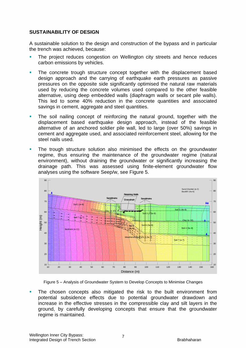
The trough structure solution also minimised the effects on the groundwater regime, thus ensuring the maintenance of the groundwater regime (natural environment), without draining the groundwater or significantly increasing the drainage path. This was assessed using finite-element groundwater flow analyses using the software Seep/w, see Figure 5.
Figure 5 – Analysis of Groundwater System to Develop Concepts to Minimise Changes
The chosen concepts also mitigated the risk to the built environment from potential subsidence effects due to potential groundwater drawdown and increase in the effective stresses in the compressible clay and silt layers in the ground, by carefully developing concepts that ensure that the groundwater regime is maintained.
Sanddrains SanddrainsCrossdrain
Retaining Walls
Clay (e-10)
Weathered Bedrock (1.5e-7)
Soil 1 (e-8)
Soil 3 (7.5e-8)
Soil 4 (5e-8)
Soil 5 (4e-8)
Bedrock (e-11)
Sanddrains Sanddrains
Clay (e-10)
Soil 6 (5e-8)
Crossdrain
Retaining Walls
Soil 7 (e-7)
Soil 8(5e-9)
Soil 7 (e-7)
Sand blanket (e-2)Backfi ll (4e-6)
Distance (m)10 20 30 40 50 60 70 80 90 100 110 120 130 140 150 160
10
20
30
40
50
60
70
80
90
Hei
ght (
m)
10
20
30
40
50
60
70
80
90

Wellington Inner City Bypass: Integrated Design of Trench Section Brabhaharan
8
MEASURES TO ENSURE LONG-TERM PERFORMANCE Appropriate design measures were developed and constructed to ensure long-term performance. These included: The trough structure was designed for the high groundwater conditions, to ensure
the groundwater regime is maintained as discussed above. Subsoil drains were provided behind the walls to prevent groundwater pressures exceeding design levels, either due to exceptionally wet weather or due to any breakage of services such as water mains.
The reinforced concrete trough was also designed to be watertight without movement joints and water stops. Watertightness is achieved by providing reinforcement complying with the requirements of AS 3735 ‘Concrete Structures for Retaining Liquids’ for fully restrained cast in situ concrete, including across all construction joints. This level of reinforcement limits design crack widths to no more than 0.1 mm. This is to ensure the durability of the concrete structure with groundwater pressures outside.
The vulnerable steel Reid bars used as soil nails were double corrosion protected by grouting in the bar in a corrugated plastic sheath, to provide a long life even in Wellington’s maritime environment. Double corrosion protection is achieved by the plastic sheath and the pre-grout under factory conditions, with the corrugated sheath ensuring that any cracking is distributed and are micro-cracks (Figure 6). The outer grout into the ground is not relied upon for corrosion protection.
Figure 6 – Double corrosion Protected Soil Nails Pre-grouted in Sheath for Installation
The reinforcement used in the shotcrete for the facing of the soil nailed walls was galvanised to provide durability.
Where the bedrock is shallow, artesian pressure relief wells were drilled into the rock to relieve the artesian pressures, and prevent instability of the excavation and reduce water pressures below the road surface. The wells were designed with an outflow to the stormwater system, and with head details and size that allow access for pumps to be lowered down the wells so that the wells can be flushed out by pumping, facilitating future maintenance to ensure the functioning of the wells.
Wellington Inner City Bypass: Integrated Design of Trench Section Brabhaharan
9
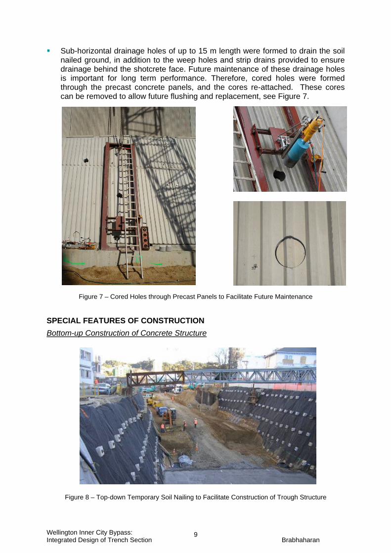
Sub-horizontal drainage holes of up to 15 m length were formed to drain the soil nailed ground, in addition to the weep holes and strip drains provided to ensure drainage behind the shotcrete face. Future maintenance of these drainage holes is important for long term performance. Therefore, cored holes were formed through the precast concrete panels, and the cores re-attached. These cores can be removed to allow future flushing and replacement, see Figure 7.
Figure 7 – Cored Holes through Precast Panels to Facilitate Future Maintenance
SPECIAL FEATURES OF CONSTRUCTION Bottom-up Construction of Concrete Structure
Figure 8 – Top-down Temporary Soil Nailing to Facilitate Construction of Trough Structure

Wellington Inner City Bypass: Integrated Design of Trench Section Brabhaharan
10
As excavation advanced downwards in stages, top-down excavation stability was achieved by installing temporary screw soil nails and drilled and grouted soil nails, see Figure 8. A drainage blanket was placed at the bottom of the excavation, to allow drainage across the alignment, and then the reinforced concrete trough structure was constructed bottom-up, see Figure 9.
Figure 9 – Bottom-Up Construction of Reinforced Concrete Trough Structure
The temporary screw nails were removed wherever possible as the completed structure was backfilled, see Figure 10.
Figure 10 – Completion of Reinforced Concrete Trough Structure
Top-down Construction of Soil Nailed Walls One of the key features of the soil nailed walls was that they were able to be constructed top-down, with excavation in stages and support of the excavation using soil nails and shotcrete facing, see Figure 11. This ensured the stability of the excavation at all times, given the weak ground conditions and the close proximity of local roads and services as well as the existing Ghuznee Street overbridge.

Wellington Inner City Bypass: Integrated Design of Trench Section Brabhaharan
11
Figure 11 - Top-down Construction of Soil Nailed Wall, and Post Grouting Trials and Testing of Nails
Post-grouting of Soil Nails Construction of the soil nails in the poor and variable ground conditions required testing of the soil nails during the design and construction stages (Figure 11), and incorporation of special features such as post-grouting (Brabhaharan, 2007b). Post-grouting comprised pressure grouting the ground-grout interface: by breaking the primary grout with water pressure through post-grout tubes, and then pressure grouting through these tubes and the cracked primary grout.
Post-grouting was used for the soil nails: to ensure that the soil nail holes are completely filled with ground to achieve a
good soil-grout bond capacity in the variable soils, without water testing, pre-grouting, re-drilling and grouting-in soil nails, which is a slow and difficult process.
to enhance ground-grout bond capacity of soil nails in poor ground conditions. Post-grouting achieved a significant increase in the ground-grout bond capacity (Brabhaharan, 2007b), ensuring the feasibility of soil nailing in the poor ground. CONCLUSIONS The Wellington Inner City Bypass provided an integrated sustainable solution to the difficult ground, groundwater and seismic conditions in an urban environment. This case study demonstrates that sustainable solutions can be achieved through integrated consideration of issues, in this case by minimising the disruption to the groundwater regime; and by using the inherent ground strength - its passive resistance to resist earthquake loads on the trough structure, and by reinforcing the natural ground using soil nails (rather than constructing massive or deep walls to achieve the support of high trench walls in poor ground). Such solutions are not only more sustainable by minimising the use of scarce resources, the carbon footprint and effects on the natural and built environments, but are also cost effective. We should be willing to develop innovative solutions, such as use of post-grouting in poor and variable ground, to achieve these outcomes.

Wellington Inner City Bypass: Integrated Design of Trench Section Brabhaharan
12
The case study also demonstrates how whole of life performance can be built into design and construction, by careful attention to seismic design (such as the use of displacement based design), durability and detailing to facilitate future maintenance. Figures 12 and 13 show the completed trench structure for the bypass.
Figure 12 – Completed Trench Structure
Figure 13 – Completed Reinforced Concrete Trough Structure
ACKNOWLEDGEMENTS We acknowledge New Zealand Transport Agency’s permission to publish this paper. REFERENCES Brabhaharan, P (2007a). Performance-based Earthquake Design and Construction
of the Wellington Inner City Bypass, Wellington. NZ Society for Earthquake Engineering Annual Conference. 30 March - 1 April 2007. Palmerston North.
Brabhaharan, P (2007b). Innovation in Soil Nail Design and Construction in New Zealand. 10th Australia-NZ Conf on Geomechanics. Brisbane. October 2007.
Brabhaharan, P, Atkinson, K, Taylor-Koolen, T & Fulton, R (2006). Trench Design & Construction for the Wellington Inner City Bypass. New Zealand Concrete Industry Conference’06. Christchurch 2006. 28 September to 1 October 2006.
Transit New Zealand (1999). Bridge Manual.