uber-bot proposal - gahzelle.files.wordpress.com · this proposal is for the design of an uber-bot,...
TRANSCRIPT

UBER-Bot Proposal TEAM #15
ENPH 253, UBC
JUNE 16 TH , 2016
SUBMITTED TO:
Andre Marziali
Bernhard Zender
Jon Nakane
Pamela Rogalski
SUBMITTED BY:
Aashish Karna #32097140
Eileen Ong #42038159
Koosha Rezaiezadeh #15915144

1
EXECUTIVE SUMMARY This proposal is for the design of an UBER-Bot, an autonomous robot that picks up toy
“passengers” and drops them at the designated location. The main objective is to have the
robot compete in time for passengers with another robot on the Playing Surface. The surface
will be approximately 8’ x 16’, with tape paths that allow robots to access di�erent areas of the
surface. In this way, the primary means of navigation is infrared (IR) detection with an added
algorithm to systematically search for passenger locations. Passengers will be placed on IR
Bases that emit the signal in every direction and the Destination Marker is also an IR beacon.
To achieve the objective of the competition, we have come up with a design for an UBER-Bot.
The Overview of Basic Strategy section provides details of the robot behaviour in the Playing
Surface, and therefore includes the expected functionalities in more details. Following
sections of this proposal will elucidate the initial design (broken down into di�erent
components).
Our mechanical design for the chassis includes two main components, the body and the
extending arm. After cost and mechanical considerations, we have come up with one design
for the body and two possible design for the arms. The secondary arm design will only be
pursued if the design for body fails to accurately detect the position the IR beacons while
picking up the toys. In the mechanical aspect, we have made appropriate calculations in
making decisions regarding the material and geometry of each part, as well as in selecting the
required motors to get su�cient torques. The main body will take on a cylindrical shape with
12” diameter and 4” height, and most of the components (all except the arm and some
sensors) will be contained in this space.
For the drive system, we have decided to eliminate the use of H-Bridges in the wheel motors,
due to the lightweight and low moment of inertia of the body. However, in the case that more
thrust force is required, we will allocate space in the design for H-Bridges. This section will
cover the design for each IR detecting system used in the robot. Moreover, we ensured that
there are su�cient analog and digital pins on the TINAH for the robot to function by
incorporating circuits that would reduce the number of inputs and systematic mechanical
design that would reduce the number of motor outputs.
The software aspect will include the tape following, passenger pick-up and drop-o�, collision,
and general navigation functions. These functions will be used depending on the di�erent
states the robot is at during its runtime.
The �nal sections of the document provides an overview of the timeline for the 4-week
construction period. Details of the plan and process, including risk assessments and how to
handle such risks are also described.

2
TABLE of CONTENTS Preface . . . . . . . . . . . . . . . . . . . . . . . . . . . . . . . . . . . . . . . . . . . . . . . . . . . . . . . . . . . . . . . . . . . . . . . . . . 5
Overview of Basic Strategy . . . . . . . . . . . . . . . . . . . . . . . . . . . . . . . . . . . . . . . . . . . . . . . . . . . . . . . . .6
Chassis . . . . . . . . . . . . . . . . . . . . . . . . . . . . . . . . . . . . . . . . . . . . . . . . . . . . . . . . . . . . . . . . . . . . . . . . . . 7
Main Body . . . . . . . . . . . . . . . . . . . . . . . . . . . . . . . . . . . . . . . . . . . . . . . . . . . . . . . . 7
Arm . . . . . . . . . . . . . . . . . . . . . . . . . . . . . . . . . . . . . . . . . . . . . . . . . . . . . . . . . . . . . 8
Ease of Assembly . . . . . . . . . . . . . . . . . . . . . . . . . . . . . . . . . . . . . . . . . . . . . . . . . 9
Flexibility . . . . . . . . . . . . . . . . . . . . . . . . . . . . . . . . . . . . . . . . . . . . . . . . . . . . . . . . 10
Mass . . . . . . . . . . . . . . . . . . . . . . . . . . . . . . . . . . . . . . . . . . . . . . . . . . . . . . . . . . . . 10
Method of Assembly . . . . . . . . . . . . . . . . . . . . . . . . . . . . . . . . . . . . . . . . . . . . . . . 11
Drive and Actuator System . . . . . . . . . . . . . . . . . . . . . . . . . . . . . . . . . . . . . . . . . . . . . . . . . . . . . . . . 12
Driving . . . . . . . . . . . . . . . . . . . . . . . . . . . . . . . . . . . . . . . . . . . . . . . . . . . . . . . . . . 12
Claw . . . . . . . . . . . . . . . . . . . . . . . . . . . . . . . . . . . . . . . . . . . . . . . . . . . . . . . . . . . . 13
Electrical Design . . . . . . . . . . . . . . . . . . . . . . . . . . . . . . . . . . . . . . . . . . . . . . . . . . . . . . . . . . . . . . . . . 15
Input/Output Pins . . . . . . . . . . . . . . . . . . . . . . . . . . . . . . . . . . . . . . . . . . . . . . . . . 15
IR Detectors . . . . . . . . . . . . . . . . . . . . . . . . . . . . . . . . . . . . . . . . . . . . . . . . . . . . . 16
QRD Sensor . . . . . . . . . . . . . . . . . . . . . . . . . . . . . . . . . . . . . . . . . . . . . . . . . . . . . 18
Collision Sensor . . . . . . . . . . . . . . . . . . . . . . . . . . . . . . . . . . . . . . . . . . . . . . . . . . 19
Destination Direction . . . . . . . . . . . . . . . . . . . . . . . . . . . . . . . . . . . . . . . . . . . . . 19
PCBs . . . . . . . . . . . . . . . . . . . . . . . . . . . . . . . . . . . . . . . . . . . . . . . . . . . . . . . . . . . .20
Software Code and Algorithm . . . . . . . . . . . . . . . . . . . . . . . . . . . . . . . . . . . . . . . . . . . . . . . . . . . . . 21
Tape Following . . . . . . . . . . . . . . . . . . . . . . . . . . . . . . . . . . . . . . . . . . . . . . . . . . 21
Collision . . . . . . . . . . . . . . . . . . . . . . . . . . . . . . . . . . . . . . . . . . . . . . . . . . . . . . . . 22
Passenger Pick-up/Drop-o� . . . . . . . . . . . . . . . . . . . . . . . . . . . . . . . . . . . . . . . 23
` Navigating Intersections . . . . . . . . . . . . . . . . . . . . . . . . . . . . . . . . . . . . . . . . . . 24

3
Error Handling/Dealing with “Lost” States . . . . . . . . . . . . . . . . . . . . . . . . . . . 25
Risk Assessment and Contingency Planning . . . . . . . . . . . . . . . . . . . . . . . . . . . . . . . . . . . . . . . 26
Task List, Major Milestones, Team Responsibilities . . . . . . . . . . . . . . . . . . . . . . . . . . . . . . . . . . 27
Task List . . . . . . . . . . . . . . . . . . . . . . . . . . . . . . . . . . . . . . . . . . . . . . . . . . . . . . . . 27
Major Milestones . . . . . . . . . . . . . . . . . . . . . . . . . . . . . . . . . . . . . . . . . . . . . . . . 28
Team Responsibilities . . . . . . . . . . . . . . . . . . . . . . . . . . . . . . . . . . . . . . . . . . . . 28
Document Contribution Summary . . . . . . . . . . . . . . . . . . . . . . . . . . . . . . . . . . . . . . . . . . . . . . . . . 29
Reference/Appendices . . . . . . . . . . . . . . . . . . . . . . . . . . . . . . . . . . . . . . . . . . . . . . . . . . . . . . . . . . 30

4
LIST of TABLES and FIGURES
Figures
Figure 1. Base . . . . . . . . . . . . . . . . . . . . . . . . . . . . . . . . . . . . . . . . . . . . . . . . . . . . . . . . . . . . . . . . . . 7
Figure 2. Complete Chassis . . . . . . . . . . . . . . . . . . . . . . . . . . . . . . . . . . . . . . . . . . . . . . . . . . . . . . 8
Figure 3. Arm . . . . . . . . . . . . . . . . . . . . . . . . . . . . . . . . . . . . . . . . . . . . . . . . . . . . . . . . . . . . . . . . . . . 9
Figure 4. IR Detector Circuit System . . . . . . . . . . . . . . . . . . . . . . . . . . . . . . . . . . . . . . . . . . . . . . . 17
Figure 5. Multiplexer Circuit for Ampli�cation Selection . . . . . . . . . . . . . . . . . . . . . . . . . . . . . . 18
Figure 6. QRD Sensor Diagram . . . . . . . . . . . . . . . . . . . . . . . . . . . . . . . . . . . . . . . . . . . . . . . . . . . 19
Figure 7. Destination Detector Circuit . . . . . . . . . . . . . . . . . . . . . . . . . . . . . . . . . . . . . . . . . . . . . . 20
Figure 8. Tape Following Function State Diagram . . . . . . . . . . . . . . . . . . . . . . . . . . . . . . . . . . . 21
Figure 9. Collision Function State Diagram . . . . . . . . . . . . . . . . . . . . . . . . . . . . . . . . . . . . . . . . . 22
Figure 10. Passenger Pick-up/Drop-o� Function State Diagram . . . . . . . . . . . . . . . . . . . . . . . 23
Figure 11. Intersection Navigation Function State Diagram . . . . . . . . . . . . . . . . . . . . . . . . . . . .24
Tables
Table 1. Main Body Parts . . . . . . . . . . . . . . . . . . . . . . . . . . . . . . . . . . . . . . . . . . . . . . . . . . . . . . . . . 8
Table 2. Arm Parts . . . . . . . . . . . . . . . . . . . . . . . . . . . . . . . . . . . . . . . . . . . . . . . . . . . . . . . . . . . . . . 9
Table 3. Mass of the robot and its components . . . . . . . . . . . . . . . . . . . . . . . . . . . . . . . . . . . . . 10
Table 4. Digital Pins Used . . . . . . . . . . . . . . . . . . . . . . . . . . . . . . . . . . . . . . . . . . . . . . . . . . . . . . . 15
Table 5. Analog Pins Used . . . . . . . . . . . . . . . . . . . . . . . . . . . . . . . . . . . . . . . . . . . . . . . . . . . . . . 15
Table 6. Servo Output Pins Used . . . . . . . . . . . . . . . . . . . . . . . . . . . . . . . . . . . . . . . . . . . . . . . . 15
Table 7. Motor Output Pins Used . . . . . . . . . . . . . . . . . . . . . . . . . . . . . . . . . . . . . . . . . . . . . . . . . 16
Table 8. Destination Detector Logic Gate Truth Table . . . . . . . . . . . . . . . . . . . . . . . . . . . . . . . 20
Table 9. Circuits and Respective Space Allocations . . . . . . . . . . . . . . . . . . . . . . . . . . . . . . . . .20
Table 10. Risk Assessment and Contingency Planning . . . . . . . . . . . . . . . . . . . . . . . . . . . . . . .26
Table 11. Team Responsibilities . . . . . . . . . . . . . . . . . . . . . . . . . . . . . . . . . . . . . . . . . . . . . . . . . . . 28
Table 12. Document Contribution Summary . . . . . . . . . . . . . . . . . . . . . . . . . . . . . . . . . . . . . . . . 29

5
PREFACE The authors of this proposal are three 2 nd year Engineering Physics students in the University
of British Columbia.
We would like to thank Dr. Nakane, Dr. Marziali, and Dr. Zender for sharing their technical
knowledge during our design and process. As well, Prof. Rogalski for her tremendous help
during the writing process of this proposal.
Each section of this proposal was written separately by each author (refer to pg. 13: Document
Contribution Summary), then reviewed altogether.
This proposal contains no con�dential material and can be re-printed without permission.

6
OVERVIEW of BASIC STRATEGY ● STARTING OFF
○ Tape-following will direct the robot
○ Goes at a constant speed of approximately 1.0 m/s
○ Passenger-searching mode active (during both intersections and tape
following)
● PASSENGER-SEARCHING MODE
○ Tape-following directs the robot
○ IR detector on the front searching for passengers
○ At intersections, go in the path with the direction of highest IR level detected. If
none is detected, go on a random path
○ When IR detector in the arm detects a signal that is higher than threshold level,
stop robot and reposition for passenger pick-up
● PASSENGER PICK-UP
○ Tape-following is on; in case of collision, it records the last error, but does not
control wheel torque
○ Lower claw until passenger pushes on sensor, then close claws
○ Switch to destination searching mode
○ Retract claw then depart
● DESTINATION-SEARCHING MODE
○ Tape following guides the robot
○ IR sensors on tower search for destination beacon
○ At intersections, go in the path with direction of highest IR level detected.
○ When IR detector signal is higher than threshold level, stop robot and
reposition for passenger drop-o�
● PASSENGER DROP-OFF
○ Tape-following is on; in case of collision, it records the last error, but does not
control wheel torque
○ Lower claw to maximum extension distance, then open claws to drop
passenger
○ Retract claw then depart
● COLLISION
○ Stop moving
○ Reverse, full power, for a really short time
○ Immediately turn 180° if still on tape
○ If not, use last error to �nd tape
○ Continue tape following once tape found

7
CHASSIS
MAIN BODY
The chassis consists of 2 �at boards with circular edge faces on the fore and aft of the robot,
and straight edges on the sides. The bottom board, also known as the base, houses the
drivetrain. Motors, along with wheel mounts and the batteries will be placed on the base. All
circuit components for the drivetrain as well as the QRD sensors will be located here too. The
motors will be placed in mounts, which will be bolted onto the board using brackets. The
motors and the mounts can be glued on as well. The batteries and the PCBs will be held in
place using velcro straps.
The second board will be connected to the base using the body spacers. The rest of the
body, including the the arm and claw, will be housed on this board. The TINAH will also rest
here, held in place with 4 screws.
For the main body, we decided to use a wooden board rather than sheet metal base to
reduce deformations due to shear force and to make our design as light as possible.
The entire robot will not exceed the 12” limit (including the wheels and bumpers), as shown in
the following diagram:
Figure 1. Base

8
Figure 2. Complete Chassis
The following table lists each part of the main body:
Table 1. Main Body Parts
Part Material/Production Quantity
Base Wood board + sheet metal, laser cutter + water jet 2
Arm support walls Acrylic, laser cutter 2
Ball bearings To be purchased 4
Ball bearing mounts Plastic, laser cutter 4
Motor mounts steel , water jet 2
Spacers Plastic, machined 6
Axle Steel, machined 2
Wheel gears To be purchased (5:1) 2
Main wheel Acrylic or plastic + rubber/friction rims 2
Caster wheel To be purchased 2
Bumper Sheet metal, water jet + rolling machine 2
Bumper spring Light spring, to be purchased 4
Bumper hinge To be purchased 4
ARM
The design for our arm will allow extension and retraction of a claw that will hold the
passenger. This is so that the arm extends out only when picking up or dropping o� the
passenger and there will be no parts overhanging the main body, as stated in the rules of the

9
competition. To do so, we have decided to build a cart that is attached to bearing drawer rails.
This cart has an attached claw and will be driven up and down the rail by a pulley system and
a motor. The following diagram provides a visual for our design:
Figure 3. Arm
A further assessment of the forces on the arm resulted in the following selection for material
and geometry for each part:
Table 2. Arm Parts
Part Material/Production Quantity
String Twine 1
Pulley Plastic, to be purchased 2
Claw Acrylic, laser cutter 6
Claw Gears Acrylic, laser cutter 6
Other Gears To be purchased or made
Cart Acrylic, laser cutter 1
Drawer slide To be purchased 2
Sensor mount Steel, machined 1

10
EASE of ASSEMBLY
● For easy removal, the TINAH will be secured using 4 screws at the top layer of the
body and the battery will be strapped down to the exposed lower back of the robot
using velcro.
● All fasteners can easily be removed without causing any damage to the component or
chassis itself (eg. no components glued to chassis, use screws instead)
FLEXIBILITY
● The arm is a completely separate piece from the body so that it can be made and
tested before mounted onto the body. Any major changes to the arm will not a�ect the
main body design.
● We allow adjustments for more space (eg. to mount PCBs) by adding spacers between
the two layers of the robot.
● The size of motors used can be increased in case a more powerful one is required
● Wheel and axle mounts can easily be adjusted in case a larger wheel is required
● For the PCBs, we added a large tolerance for the size estimation.
● The height of IR sensors can easily be adjusted by adding spacers.
● Both the pulley and claw system can �t other gear ratios if a larger one is needed.
MASS
Table 3. Mass of the Robot and its components
Component Approximate Mass
Arm supports 560 g
Cart 190 g
Main Body (including motors, TINAH, etc) 2200 g
Total Mass of Robot 2950 g
11
METHOD of ASSEMBLY
We will divide the chassis production process into two parts, the body and the crane, done
simultaneously. For the body, there will also be two parts, the lower (base) and upper (roof)
which are completely separate from each other.
BASE
1. Motors are mounted to the base using screws and nuts.
2. The axle and bearing mounts will be easily movable to match the gear ratio to the
motor.
3. PCBs are then secured using plastic screws, with a layer of sponge between the PCBs
and chassis to eliminate stress on the components.
4. Spacers are placed along the edge of the base.
5. Hinges are used to attach the bumpers to the base, with collision sensors mounted
behind them.
ROOF
1. For the upper part, the TINAH is screwed down to the roof.
2. The crane supports and motor will be mounted on either sides of the TINAH after the
arm assembly and testing are done.
CRANE
1. The cart along with the claw and gears will be assembled �rst.
2. Each slider is screwed to the supporting walls diagonally.
3. One side of the cart will be secured to one slider and the other side will be loosely
attached to the other slider
4. The destination IR sensor will be mounted last, on top of the walls using brackets

12
DRIVE and ACTUATOR SYSTEM
DRIVING
For driving, the robot will use two Geared Barber Coleman motors. Each motor will be
connected to a wheel of diameter 8 cm. We will be using a gear ratio of 5 : 1. The wheels are
positioned in the center opposite sides of the robot. For steering, the motors for each wheel
will provide di�erent power, causing each wheel to rotate at a di�erent speed. This enables
the robot to steer with agility. The positioning of the motors also allow the robot to rotate 180 0
on the spot.
Since it is hard to measure the friction on the gears in the motors, it is di�cult to approximate
the maximum rpm of the motor. As a result, we based our calculations of maximum torque on
the initial acceleration and velocity of the robot starting from rest. Approximating the mass of
the robot and using reasonable values for velocity and acceleration gives us:

13
Furthermore, we also approximated the maximum torque required to turn the robot. We
calculated the maximum torque needed to turn the robot on the spot at a speed of 2 rev/s:
By using the calculations shown, we conclude that the gear ratio and the motor types chosen
are ideal for our robot.

14
CLAW
The picking up mechanism consists of two claws connected to the arm. The claws close
towards each other and mesh, causing the passenger to be caught. Based on the calculation
below, the force obtained from the servo motor (HK15138) controlling the claw would be
approximately 6.36 N, which is su�cient for picking up a toy passenger.
The claw and its servo motor will be mounted onto drawer rails. A motor attached to a system
of pulley will be programmed to extend and retract the rails. We calculated the torque
required to pull up the claw system to be 19N.mm. So a small ungeared motor is more than
su�cient.

15
ELECTRICAL DESIGN
INPUT/OUTPUT PINS
Table 4. Digital Signal
Sensor Description Pins on TINAH Total Pins
QRD Tape following sensors D0-D1 2
QRD intersection detectors D2-D5 4
Claw sensor (micro-switch) D8-D9 2
Angle of the destination D6-D7 2
Collision sensors D10-D11 2
Table 5. Analog Signal
Sensor Description Pins on TINAH Total Pins
IR detectors (side) to accurately locate the passenger A0-A2 3
IR detectors (front) to decide on the intersection A3-A5 3
IR destination detectors A6-A7 2
Table 6. Servo Outputs
Sensor Description Pins on TINAH Total Pins
Claw 1 1

16
Table 7. Motor Outputs
Sensor Description Pins on TINAH Total Pins
Tape following motor M0-M1 2
Arm motor M2 1
IR destination detector motor M3 1
IR DETECTORS
We will use OP805s for detecting IR to locate the toy passengers, decide on which direction
to choose in an intersection, and �nd the destination.
● 3 OP805s will be positioned at the front of the robot pointing to the left, right, and
front to detect the incoming IR from the beacons in order to decide what path to take
at an intersection. The value of each of these sensors needs to go through DC
�ltering, a small ampli�cation(x2), AC �ltering, a higher ampli�cation(around x300 - this
number will be optimized in the testing phase), and peak detection.
● Another 3 OP805s will be used to locate the passenger beacons, 2 at the side of the
robot that has the claw and one in the opposite side. These sensors should also pass
all the �ltering in order to get a dc peak value. Moreover, since the side that has the
claw needs to be accurately positioned in front of the toy, we will use the di�erence in
the peak values of two IR sensors next to each other as an indicator of how far we are
from the center of the toy. These three sensors need lesser ampli�cations(around x30)
which will also be optimized during the testing phase.
● Similar to the system used for locating the toys accurately in front of the claw, we will
use the �lter output of two IR sensors positioned on a tower to �nd the relative angle
and the distant of the robot from the destination. The values of these sensor should
pass through the �lters and ampli�ers and peak detector as well. However, since the
distant of the robot from the destination beacon varies a lot( from 20” to around 150”),
we will need to use multiple ampli�ers with di�erent ampli�cations in order to get a
value that is readable for TINAH.

17
The circuits used for IR detections are as follows:
Figure 4. IR Detector Circuit Diagram
otal Amplif ication R1 R2 T = 2 /

18
Figure 5. Using a multiplexer for di�erent ampli�cations In the diagram below A1, A2, and A3 are the ampli�ed peak output of the IR detectors, where A1 > A2 > A3.
QRD SENSORS
QRD1114 are re�ective object sensors that consist of an infrared emitting diode and an NPN
phototransistor. The output values of the QRD change when objects of di�erent re�ectivities
are placed in the front of the sensor.
The robot will utilize 6 of these sensors to help navigate the competition surface. The output
of the QRDs will be compared against a threshold using comparators, before being input into
the digital section of the TINAH.

19
Figure 6. QRD Sensor Circuit Diagram
COLLISION SENSORS
The collision sensors are small mirco-switches or sub-microswitches that give a digital output
when the switch is pressed (activated). These sensors are used to detect contacts between
the robot and the external environment. There will be 4 of these sensors used in the robot: 2
placed behind the bumpers (front and back), 1 on the claw to detect if the toy has been
grabbed properly, and 1 to stop the motor when the claw has been fully retracted.
DESTINATION DIRECTION
The destination beacon is detected using two OP-805 sensors mounted atop of a
potentiometer on a tower. The range of the potentiometer is split into 4 sections/quadrants (
V 0 → V 1 , V 1 → V 2 , V 2 → V 3 , V 3 → V 4 ). The sensors read the IR and the software takes the
di�erence of the two. Based on the inputs, the software repositions the sensors so that they
are facing the destination beacon.
Once the beacon is located, the value of the potentiometer is read. This value is compared to
the boundaries of the 4 quadrants and the comparisons produce a 2-bit digital value. This
value can then be looked up in a truth table that has 4 entries that corresponding to the 4
di�erent quadrants. These 2-bit values go through a series of logic gates, the output of which
is used by the program to instruct the robot on which direction to turn in at the next
intersection.

20
Figure 7: Destination Detector Circuit Diagram
Table 8. Destination Detector Logic Gate Truth Table
Voltage D2 D1
V 0 → V 1 0 0
V 1 → V 2 0 1
V 2 → V 3 1 1
V 3 → V 4 1 0
PCBs
In the design, All PCBs will be secured to the base by a strap, with sponge padding in
between to prevent any damage to the circuits. The ground for each PCB will be connected to
the TINAH ground.
Table 9. Circuits and Respective Space Allocations
Circuit(s) PCB Size Quantity Location in Robot Wiring
QRDs + Collision Sensors
5 cm x 8 cm 1 Lower front Ribbon cable to TINAH, Solid core to QRDs
6 IR detector circuits 5 cm x 24 cm 1 Lower front to center
Shielded wire to sensors, Ribbon cable to TINAH
ADC for Destination Detector
5 cm x 4 cm 1 Upper front Solid core to TINAH and potentiometer
H-Bridge (tentative) 5 cm x 8 cm 2 Lower back, beside battery
Shielded wire to TINAH and motors

21
SOFTWARE CODE and ALGORITHM
OVERVIEW
The code that will be uploaded to the robot involves 4 major components, each of which are
described in detail below. These 4 components will be used in conjunction with each other,
allowing the robot to carry out speci�c tasks with ease. The major components will be backed
up with extra code to be able to handle any error states.
TAPE FOLLOWING
Our robot uses this function to manoeuvre itself through the arena. The robot moves along
the paths by following the tape that is used to mark the pathways.
The values from the two QRD sensors are used as inputs into this function. These input values
are then compared to preset threshold values and using this comparison, the robot makes
necessary changes to its output in order to correct its motion on the path.
The changes in the output are as a result of the PID system incorporated into the function.
The PID system makes calculations based on how far o� the robot is from its desired path.
A basic outline of the function is shown below:
Figure 8. Tape Following Function State Diagrams

22
The ‘hard’ and ‘soft’ steering refers to how the error values are changed on the PID system.
“Soft” is de�ned as a small increase and “hard” is de�ned as a large increase, in error value.
“Left” and “right” correspond to negative and positive error values respectively.
COLLISION
During the competition, collisions with another robot or the curb may occur. To avoid the robot
being trapped in such situations, a collision prevention algorithm is built into our program.
With the help of two bumpers (fore and aft) connected to micro-switches, the robot will be
able to work its way out of any collision.
The values from the micro-switches are digital inputs. If the switches were activated, the robot
will stop its driver motors. It will then accelerate at full power for a really short time, in the
direction opposite to the switch that was activated, before turning a 180° on its spot until it
�nds the tape again.
Figure 9. Collision Function State Diagram
23
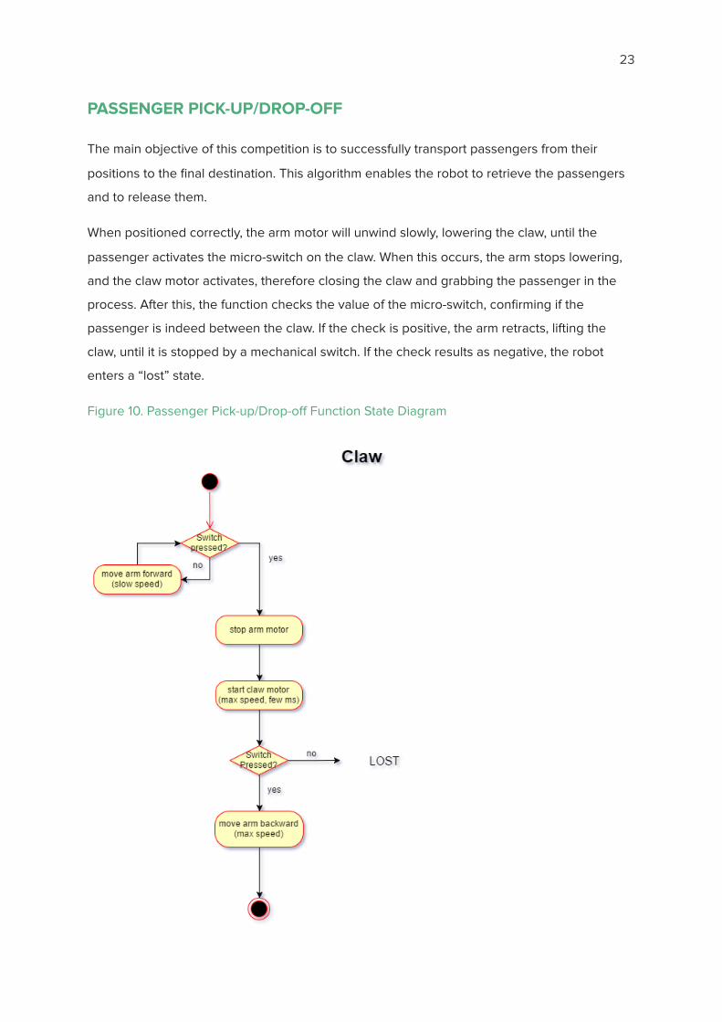
PASSENGER PICK-UP/DROP-OFF
The main objective of this competition is to successfully transport passengers from their
positions to the �nal destination. This algorithm enables the robot to retrieve the passengers
and to release them.
When positioned correctly, the arm motor will unwind slowly, lowering the claw, until the
passenger activates the micro-switch on the claw. When this occurs, the arm stops lowering,
and the claw motor activates, therefore closing the claw and grabbing the passenger in the
process. After this, the function checks the value of the micro-switch, con�rming if the
passenger is indeed between the claw. If the check is positive, the arm retracts, lifting the
claw, until it is stopped by a mechanical switch. If the check results as negative, the robot
enters a “lost” state.
Figure 10. Passenger Pick-up/Drop-o� Function State Diagram

24
NAVIGATING INTERSECTIONS
The competition arena involves multiple intersections and our robot has to make decisions on
which way to go. This function allows our robot to select the best possible path to take when
presented with an intersection.
The function uses the input from the two tape-follower QRDs and four extra QRDs positioned
on the diagonals of the tape-follower QRDs. When the robot reaches an intersection, the two
QRDs on the top diagonal provide values regarding the availability of tape paths. The function
sets �ags for left and right if the respective paths exist and are detected by the sensors. The
two tape-follower QRDs indicate the presence of a path straight ahead and sets its respective
�ag. When either of the two QRDs on the rear diagonal detect the tape, the function performs
a multiplication of the path �ags that were initially with the readings from the forward IR
detectors. Based on this calculation, the robot turns towards the direction of an existing path
with the highest detected IR level.
If no clear di�erence can be made between the directions (eg no IR on all sides), then the
function allows the robot to randomly choose the direction it wants to continue in.
Figure 11. Intersection Navigation Function State Diagram

25
ERROR HANDLING / DEALING WITH “LOST” STATE
As described in the various functions above, there could be a possibility that the robot enters
a state in which it does not know what to do next. To avoid these scenarios, the software will
contain algorithm on appropriately dealing with “lost” states.
For picking up/ dropping o� passengers, it can be possible for the switch on the claw to be
deactivated even after the claw has closed. This would mean that either the passenger has
slipped out, or was not caught in the �rst place. To deal with this, the robot will open its claw,
retract it back without anything, and restart the passenger searching process. Another
possible solution involves retracting the claw in whatever state the claw may be, so that if the
passenger was grasped by the claw, but the switch contact had become loose, the robot
would still end up taking the passenger.
For movement, the tape following process combined with the intersection detecting process
ensures the robot always stays on the competition surface. If at all, during the testing phase,
the robot does tend to veer o� the surface and over the edge, installing an ultrasonic sensor
at the front would help resolve the issue. The ultrasonic sensor will indicate if the robot is still
on the surface or peeking over the edge.
With respect to dead ends on the competition surface, the robot should be able to turn
around 180 o at the end of a taped path. If the tape path continues till the curb, the robot will
collide with the curb, enabling the ‘Collision’ function, making it turn around and back where it
came from.

26
RISK ASSESSMENT and CONTINGENCY PLANNING Table 10. Risk Assessment and Contingency Planning
Risk Condition Probability of
Occurrence
Impact to Project Changes to Work Plan
Expected Date of Risk
Decision
First arm design requires too high a positioning accuracy
25% May not be able to pick passengers 100% of the time.
Use second arm design
July 8th
IR signal range may be too large to have only 2 ampli�cation options
25% Final beacon cannot be detected, causing the robot to lose itself
Add another ampli�cation to the circuit.
July 6th
Passengers slip out of the claw
25% Passengers will not be picked. Challenge cannot be completed
Use alternative claw design
Tape following cannot �nd intersections in time
20% Will not be able to make necessary turns, thereby unable to �nish the challenge on time.
Use a hard-coded graph of the Playing Surface
Robot goes over the edge
10% Possible damage of robot, perhaps destruction.
Make changes in algorithm / PID of tape follower. Add ultrasonic sensor
Magnetic �eld generated by motors interferes with sensors
10% Sensors may go haywire. Robot cannot complete any task
Add �lters to circuit. Use shielded / twisted wires
Micro-switch on claw does not detect the passenger
10% Passengers will not be picked. Passengers can possibly be knocked o� the support as well
Improve the contact surface on the switch ensuring passenger is always detected. Change detection method?

27
TASK LIST
1. Build/Buy wheels, axles and gears
2. Select appropriate motors and servo motors, QRDs, IR sensors
3. Design and build the claw system (mechanical + electrical)
4. Write code for claw movement and IR detection
5. Test the isolated claw system and check for accuracy & e�ectiveness
6. Suggest and incorporate any changes required (change claw design if required)
Above tasks must be completed by Major Milestone day
7. Build wooden base
8. Solder PCBs for tape following
9. Assemble body, write code for tape following and test tape follower with chassis
10. Test if motors can drive robot (if H-Bridges are required)
11. Add H-bridges if necessary, then re-test
12. Add collision bumpers and check functionality
13. Assemble IR sensors (for passengers and destination) onto the chassis and test for
decision-making and travelling
14. Assemble claw and test the entire robot’s functionality

28
MAJOR MILESTONES
Detect passenger
Build all components of the passenger beacon detection circuit and write code to make it
work. Test the functionality of the sensors on the claws and check if they detect passengers
accurately. Ensure the values being sent to the TINAH are correct. If not, make changes to
design as necessary
Detect destination beacon
Build all components of the destination detection circuit and write code to make it work. Test
the sensors which will be looking for the destination beacon and ensure it follows and
repositions itself to always track the beacon. Check if the values (ampli�cations) returned to
the TINAH are correct and match the truth table as speci�ed. If not working, make changes to
design as needed.
Pick up and drop o� passenger successfully
Build the arm with its supporting walls (1 st design) and test its functioning (connect to TINAH
and run only pick-up functionality). If not successful, make necessary adjustments, or pursue
2 nd design, then re-test arm operation.
TEAM RESPONSIBILITIES Table 11. Team Responsibilities
Member Tasks Timeline
Aashish 1) Build electrical components for claw 2) Build electrical components for chassis 3) Code functions
1) Complete by Major Milestone Day
Eileen 1) Designing + building claw 2) Test working of claw and assess any
risks. Bring forth and work on changes needed
3) Code functions
1) Complete by Major Milestone Day
Koosha 1) Designing + building claw 2) Designing + building chassis 3) Build electrical components
1) Complete by Major Milestone Day

29
DOCUMENT CONTRIBUTION SUMMARY Table 12. Document Contribution Summary
Document Section Draft Writers Editors Comments
Executive Summary Eileen Koosha
Preface Eileen Koosha
Overview of Basic Strategy
Eileen Aashish
Chassis Koosha, Eileen Koosha, Eileen
Drive and Actuator System
Koosha, Aashish, Eileen
Koosha, Aashish, Eileen
Electrical Design Koosha, Aashish Aashish
Software Code and Algorithm
Aashish, Koosha Eileen
Risk Assessment and Contingency Planning
Eileen, Aashish Aashish
Major Milestones, Task List, Team Responsibilities
Eileen, Aashish Koosha
References Eileen Eileen

30
REFERENCES http://hyperphysics.phy-astr.gsu.edu/hbase/electronic/opampvar6.html
http://projectlab.engphys.ubc.ca/enph-253-2016/proposals-2016/
Hard copies of previous design proposals for the competition
Shayan Rezaiezadeh (4th year Engineering Physics)