transverse electrodes for improved dna hybridization in microchannels
TRANSCRIPT

Transverse Electrodes for ImprovedDNA Hybridization in Microchannels
Siddhartha Das and Suman ChakrabortyDept. of Mechanical Engineering, Indian Institute of Technology, Kharagpur Kharagpur 721302, India
DOI 10.1002/aic.11144Published online March 19, 2007 in Wiley InterScience (www.interscience.wiley.com).
The present study examines the modality, in which localized transverse electric fieldscan be successfully employed, to augment the rate of DNA hybridization at the capturingprobes that are located further downstream relative to the inlet section of a rectangularmicrochannel. This is in accordance with an enhanced strength of convective transportthat can be achieved, on account of increments in the wall zeta potential at the trans-verse electrode locations. In the present model, the overall convective transport, whichis an implicit function of the magnitude and the location of the transverse electrical fieldbeing employed, is essentially coupled with the surface kinetics of the bare silica walland also the kinetics that are involved in the dual mechanisms of DNA hybridization.Parameters that govern the overall transport phenomena, such as the pH of the inletbuffer, the length of the transverse electrodes, and the voltages at which these electrodesare maintained are critically examined, in an effort to obtain an optimized wall pH dis-tribution, which in turn can ensure favorable DNA hybridization rates at the capturingprobe locations. Practical constraints associated with the upper limits of the strength ofthe transverse electrical fields that can be employed are also critically analyzed, so asto ensure that an optimized rate of DNA hybridization can be achieved from the bio-microfluidic arrangement, without incurring any adverse effects associated with theoverheating of the DNA molecules leading to their thermal denaturation. � 2007 Ameri-
can Institute of Chemical Engineers AIChE J, 53: 1086–1099, 2007
Keywords: electro-osmosis, microchannel, DNA hybridization, surface kinetics
Introduction
Research investigations on DNA hybridization in presenceof microfluidic transport have attracted serious attention overrecent times, primarily motivated by an ever-increasingnecessity of optimizing the hybridization performance, intune with the stringent biotechnological demands. Startingfrom the pioneering efforts of Chan et al.,1 several research-ers have come up with reaction-diffusion models of DNAhybridization in microfluidic channels. In this respect, the re-ceptor–ligand model of Axelrod and Wang2 and the dualmechanism based hybridization model of Zeng et al.3 need
special mention. Erickson et al.4 proposed a comprehensivemodel of dynamic solid-phase oligonucleotide hybridizationkinetics, based on an approach that accounted for both thedirect hybridization from the bulk phase and hybridizationafter an initial nonspecific adsorption stage. Das et al.,5 in amore recent study, have extended the earlier models to incor-porate the effects of electro-osmotic transport on the DNAhybridization mechanisms. Utilization of electrokinetic bodyforces in such bio-microfluidic applications has primarilybeen motivated by the possibility of building efficient flowcontrol devices, without involving any moving components.Irrespective of the details of the flow actuation mechanisms,it also needs to be mentioned in this context that in principle,the DNA hybridization rates could be significantly enhancedby arranging for more efficient mixing mechanisms in theassociated fluidic systems. This is because of the fact that a
Correspondence concerning this article should be addressed to S. Chakrabortyat [email protected].
� 2007 American Institute of Chemical Engineers
AIChE JournalMay 2007 Vol. 53, No. 51086

better mixing ensures faster reaction kinetics in reactivemicrofluidic systems. Micromixing augmentation mecha-nisms, such as the use of pulsatile flows,6–8 serpentinechannels,9,10 creation of slanted wells at the floor of thechannel,11 presence of surface inhomogenities,12 surface pat-terning,13 inhomogeneous zeta potential14 etc, can thereforebe potentially explored to achieve faster DNA hybridizationkinetics in microchannels. Such arrangements, in effect, canovercome the technological constraints associated with thestringent limitations in employing large pressure gradientsand/or electric fields under practical operating conditions,leading to an optimized DNA hybridization performance,consistent with the chosen bio-microfluidic configuration.
It is well known that the axial variations in the wall zetapotential, established on account of local pH gradients, canbe utilized to modulate electro-osmotic transport in micro-channels to a significant extent in many of the biomicroflui-dic applications.15,16 However this effect is yet to be wellexploited to obtain favorable DNA hybridization patterns.Fundamentally, localized variations in the wall zeta potentialcan alter the number of hydrogen ions that can be adsorbedat the channel walls, thereby altering the electrical potentialdistribution in the vicinity. Utilizing this basic principle, sev-eral techniques, including the popular method of isoelectricfocusing,17 have been successfully employed by the researchcommunity, for the purpose of separation of analytes on thebasis of their respective isoelectric points, as a consequenceof the development of transverse potential gradients estab-lished across a pair of surface electrodes.18 In a pioneeringstudy, Molloy and Leighton demonstrated the effectivenessof employing transverse electric fields to perform binary os-cillatory cross flow electrophoresis.19 Amongst the other im-portant studies in related applications, the investigations ofChan and Chauhan on the employment of transverse electro-des for performing cyclic EFFF20 and the use of EFFF forsize-based separation of DNA molecules21 also worth specialmention. However, in case of DNA transport, systematic the-oretical guidelines are yet to be put forward, so as to exploita deliberate generation of pH gradients through a designedconfiguration of transverse electrode pairs, in an effort toaugment the rate of hybridization in electrokinetically drivenmicrofluidic systems. Such attempts, in reality, can bear sig-nificant consequences, leading towards a maximization ofDNA hybridization rates, within the constraints of a maxi-mum permissible potential gradient that can be imposed onthe microfluidic system.
The aim of the present work is to theoretically demonstratehow a strong local pH gradient, obtained by employing apair of transverse electrodes, can be effectively utilized toachieve a faster rate of DNA hybridization in a microchan-nel. The conceptual system design is exercised by avoidingany direct interference between the positioning of transverseelectrodes and surface DNA probes on the microchannelwalls, so as to provide a technological feasibility to the entirearrangement. In other words, the DNA probes are consideredto be located sufficiently downstream or upstream to thetransverse electrodes. The model, in essence, couples the sur-face kinetics, as modified by the presence of the transverseelectrodes, with the bulk transport of momentum, heat, ionicspecies, and DNA macromolecules, from the fundamentalphysico-chemical principles. Based on the mathematical
model, simulation experiments are undertaken, so as todepict the influence of the significant system parameters,such as the pH of the buffer solution at the inlet, voltages atthe transverse electrodes, and the electrode dimensions, onthe resultant DNA hybridization rates. An upper limit of theextent to which the transverse electric fields can be exploitedto augment the rate of DNA hybridization is also established,so as to constrain the associated Joule heating effects withinpermissible standards, to avoid a further thermal denaturationof the double stranded (hybridized) DNA macromolecules.To establish the afore-mentioned basic principles from a fun-damental mathematical perspective, a relatively simple con-figuration is chosen, which assumes only a pair of capturingDNA probes, positioned symmetrically on both sides of acentral electrode located on the bottom wall of a parallelplate microchannel, with another electrode of the same lengthbeing located on the upper wall, at the same axial location.For more involved designs, this arrangement can be consid-ered as a repeating monoblock, the number of which dependson the desired complexity of the system chosen, in accord-ance with the DNA hybridization rates sought. Underlyingprinciples of this simple model, therefore, can be conven-iently extended to obtain favorable hybridization patterns inmore complicated situations as well, in which there are pro-visions to employ larger numbers of DNA probes and match-ing transverse electrode pairs in the microfluidic system.
Mathematical Modeling
We consider electro-osmotic transport of an ionic solutionof water through a parallel plate microchannel, made of baresilica, of length L0, height H, and width w, with w � H anda subsequent hybridization of transported ss-DNA moleculeswith their complementary pairs that are immobilized at thetwo different probe locations along the bottom wall ofthe channel. A potential gradient is applied along the axis ofthe channel, which provides the necessary driving force forelectrokinetic transport. The magnitude of this potential gra-dient is ascertained by assigning a specified potential, f0,(given in Table 1) at the channel inlet and a zero potential atthe channel exit. Typically, f0 is so chosen that the axialelectric field becomes of the order of 105 V/m, as a commontechnological practice. In addition to this axial field, a localtransverse electric field is applied by maintaining two trans-verse electrodes at different voltages, the transverse fieldbeing confined over a limited portion of the channel lengthonly. The magnitude of this transverse field is varied in therange of 105–106 V/m, by altering the cross-electrode poten-tials. The effects of variations of the transverse potential gra-dients on the DNA hybridization are illustrated later in thisarticle. We assume that in the hybridization channel no bub-bles are being generated due to the electrochemical reactionon these transverse electrodes We consider the two DNAhybridization probes to be located at equal distances on ei-ther side of the transverse electrode. The entire arrangementis schematically represented in Figure 1. In effect, the DNAmolecules are transported by the combined actions of theelectro-osmotic and the electrophoretic migration mecha-nisms in the axial as well as in the transverse directions.Because of a negative charge on the DNA molecules, theelectrophoretic influences on those effectively oppose their
AIChE Journal May 2007 Vol. 53, No. 5 Published on behalf of the AIChE DOI 10.1002/aic 1087

electro-osmotic migration. However, the electro-osmotic mo-bility of the DNA molecules being greater than their electro-phoretic mobility, this retarding effect gets effectively over-weighed, and the DNA molecules move in the directionof electro-osmotic transport. This aspect is further elucidatedthrough the numerical simulation predictions, as discussedlater.
Convection–diffusion transport equations
The governing transport equations, under these circumstan-ces, can be described as follows.
Continuity Equation.
qrqtþr � ðr~VÞ ¼ 0 (1)
X-Momentum Equation.
qqtðruÞ þ r � ðr~VuÞ ¼ � qp
qxþr � ðmruÞ � re
qfqxþ qc
qx
8>: 9>;(2)
where re is the net electric charge density, f is the potentialdistribution due to an externally imposed electric field and cis the surface potential distribution.
Y-Momentum Equation.
qqtðrnÞ þ r � ðr~VnÞ ¼ � qp
qyþr � ðmrnÞ � re
qfqyþ qc
qy
8>>: 9>>;(3)
In both Eqs. 2 and 3, the dynamic viscosity, m, is a func-tion of temperature, given as22
Figure 1. The flow configuration.
Table 1. Summary of Boundary Conditions
Governing Equation Inlet (x ¼ 0) Outlet (x ¼ L0) Bottom Wall (y ¼ 0) Top Wall (y ¼ H)
Poisson-Boltzmann eq. (Eq. 5) c ¼ 0 qcqx ¼ 0 c ¼ z (zeta Potential) c ¼ z (zeta Potential)
Fluid flow eqs. (eq. 1–3) u ¼ uin quqx ¼ 0n ¼ 0
u ¼ 0n ¼ 0
u ¼ 0n ¼ 0
Energy conservation eq. (Eq. 13) T ¼ T? qTqx ¼ 0 �k qT
qy ¼ q00 �k qTqy ¼ q00
Conservation equation forconcentration of the cations (Eq. 8)
cHþ ¼ ðcHþ ÞintercMnþ ¼ ðcMnþ Þinter
qcHþqx¼ 0
qcMnþ
qx¼ 0
cHþ ¼ cfilmHþ exp � eckBT
� �
cMnþ ¼ cfilmMnþ exp � neckBT
� � cHþ ¼ cfilmHþ exp � eckBT
� �
cMnþ ¼ cfilmMnþ exp � neckBT
� �
Conservation eq. for concentrationof anions (Eq. 8)
cOH� ¼ ðcOH� ÞinletcXn� ¼ ðcXn�Þinlet
qcOH�qx¼ 0
qcXn�
qx¼ 0
cOH� ¼ cfilmOH� expeckBT
� �
cXn� ¼ cfilmXn� expneckBT
� � cOH� ¼ cfilmOH� expeckBT
� �
cXn� ¼ cfilmXn� expneckBT
� �
Conservation eq. for DNAconcentration (Eq. 8)
cDNA ¼ ðcDNAÞinlet qcDNAqx ¼ 0 qcDNA
qy ¼ 0 qcDNAqy ¼ 0
1088 DOI 10.1002/aic Published on behalf of the AIChE May 2007 Vol. 53, No. 5 AIChE Journal

m ¼ 2:761� 10�6 exp1713
T
� �(4)
where T is in K and m is in Pa s.Distribution of the net electric charge density, re, appear-
ing in the momentum conservation equations, can be ascer-tained by solving the Poisson–Boltzmann equation for sur-face potential distribution as
r � ðercÞ ¼ � ree0
(5)
where c denotes the electric double layer (EDL) potential, e0is the permittivity of free space, and e is the dielectric con-stant of the electrolyte, which is a function of temperature,given as22
e ¼ 305:7 exp � T
219
8>: 9>; (6)
where T is in K. In Eq. 5, re, is described as
re ¼ 103Na eXNi¼1
zici (7)
Here zi and ci are the valency and the concentration of theith ionic species, respectively, Na is the Avogadro numberand N is the total number of ionic species in the solution.The concentration of the ith ionic species is governed by thespecies-conservation equation, given by
qðrciÞqtþr�ðr~VciÞ¼r�ðrDirciÞþr�ðrmep;icirfÞþrRi
(8)
In Eq. 8, Ri is the term responsible for any reaction thatthe ionic species may undergo in the solution. The term mep,irepresents the electrophoretic mobility of the ith species,which depends on the nature of species being transported.For the ss-DNA molecules, mep,i is given by23
mep;i ¼ ½f ðkaiÞ=ð1þ kaiÞ�ezioH;i; (8a)
In Eq. 8a, k is the inverse of the Debye length, zi is thevalence of the ith type of the ss-DNA molecule (which canbe obtained through Eq. 11, as described subsequently), ai isits Stokes radius, oH,i is its hydrodynamic mobility (whichcan be expressed as oH;i ¼ 1
6pmaiand f ðkaiÞ is the Henry’s f-
function. However, for the other ionic species, the electro-phoretic mobility can be more simply expressed as
mep;i ¼ ezioH;i (8b)
In the present model, we consider simple ionic species inthe solution, with the following constituents: Hþ, OH�, Mnþ,Xn�, where Xn� is the anion corresponding to the added me-tallic cation, Mnþ. The other kind of ionic species that mightbe expected to be present in the solution will include tracesof some phosphates or sulfates, which are routinely added toalter certain properties of the solution, such as its conductiv-ity. However, these components are present in much smaller
amounts when compared with Mnþ or Xn�, and hence, theeffects of their presence are neglected in the present study.We also consider that only a single type of ss-DNA mole-cules is being transported. While considering transport of thess-DNA species, the diffusion coefficient Di, appearing inEq. 8 represents a generalized diffusion coefficient, which isthe liquid phase diffusion coefficient (D3) in the bulk fluidand surface phase diffusion coefficient (D2) at the nonspecificadsorption sites (It can be noted here that DNA hybridizationcan take place directly from the bulk phase (3D hybridiza-tion) or along the wall surface (2D hybridization) after aninitial nonspecific adsorption step.). By borrowing analogyfrom diffusion transport of polymeric chains, the diffusioncoefficients for DNA molecules can be expressed as thefunctions of the size and concentration of the ss-DNA mole-cules, along with the ionic strength of the solution. Typically,one can employ certain well-established scaling relationshipfor this purpose, for example24
Di
Di;0¼ exp �acvRd� �
(9)
where Di is the effective diffusion coefficient of a DNA mac-romolecule of radius R and concentration c, and Di,0 is thecorresponding diffusion coefficient for c ¼ 0. Experimentson a wide range of polymer systems, both biological andsynthetic,25–27 have shown that such scaling laws canadequately describe the diffusion of a polymer over a widerange of solution concentrations. From a series of investiga-tions, it has been revealed that the parameter v, as appearingin Eq. 9, typically falls in the range of 0.5–1.0, with thelower and the upper limits signifying the relative contribu-tions of hydrodynamic and direct interactions, respectively.The parameter d varies from 0 to 1, depending upon thepolymer system. The parameter a is a function of the ionicstrength of the solution given as a ; Ib, where I is the ionicstrength and b is a function of the nature of the polymer so-lution. In the present study, we estimate the earlier parame-ters by considering a total of 10 nucleotide units of ss-DNAmolecules with a hydrodynamic radius of around 1 nm, byreferring to the scaling estimates developed by Dwyer andBloomfield.24 Diffusivities of the other ionic species, how-ever, can be estimated in a more straightforward manner as
Di ¼ oH;ikBT (9a)
It also needs to be noted here that an accurate solution ofthe species conservation equation (Eq. 8) not only requires aphysically-consistent specification of the diffusion coeffi-cients, but also necessitates a correct specification of theelectro-osmotic mobilities of the ionic species, which in turndepend on the respective charges of the ionic species beingtransported. For that purpose, it can be noted that unlike thesimple ionic species, charges of the ss-DNA molecules donot remain constant for all values of the buffer pH. A quanti-tative description of the electrostatic characteristics of a ss-DNA molecule, as a function of the buffer pH, can bederived from the ionization of the phosphodiester linkages(resulting in one negative charge per nucleotide) and alsofrom ionization of bases (making the charge on the DNAbase-dependent) in an aqueous solution. A phosphodiester is
AIChE Journal May 2007 Vol. 53, No. 5 Published on behalf of the AIChE DOI 10.1002/aic 1089

a strong acid whose pK is around 1. Nucleotides which makeup the DNA molecules can be of four types differing only inthe nitrogenous base: Adenine, Thymine, Cytosine and Gua-nine. Adenine (A), and Cytosine (C) bases can be found asneutral or positive forms, whereas thymine (T) is neutral ornegative, and guanine (G) can exist in all the three states.28
The ionization of these bases can be represented as
Adenine: ½AHþ� !KA ½A� þ ½Hþ� KA ¼ 10�3:5 (10a)
Cytosine: ½CHþ� !KC ½C� þ ½Hþ� KC ¼ 10�4:2 (10b)
Thymine: ½TH� !KT ½T�� þ ½Hþ� KT ¼ 10�9:2 (10c)
Guanine: ½GHþ2 � !KG1 ½GH� þ ½Hþ� KG1
¼ 10�2:1 (10d)
½GH� !KG2 ½G�� þ ½Hþ� KG2¼ 10�9:2 (10e)
Now, assuming the probability of presence of each basetype (A, T, C, G) to be 25% per nucleotide, the average netcharge per nucleotide, C/Nnu, may be estimated as28
C=Nnu � � 1
1þ ½Hþ�=Kph
þ 0:251
1þ KA=½Hþ�þ 0:25
1
1þ KC=½Hþ� � 0:251
1þ ½Hþ�=KT
þ 0:25½Hþ�2 � KG1KG2
KG1KG2 � KG1½Hþ� þ ½Hþ�2ð11Þ
where Kph (¼10�1) corresponds to the ionization of the phos-phodiester groups. The valency term zi appearing in thespecies conservation equation for the ss-DNA molecule isidentical to the average net charge per nucleotide C/Nnu andis thus given by Eq. (11).
It can be noted here that an accurate modeling of the sec-ond term in the right hand side of Eq. 8 not only demands aconsistent description of the electro-osmotic mobilities of theconstituents, but also requires a specification of the distribu-tion of the potential field, f, which can be obtained by con-sidering the charge conservation in the liquid, in accordancewith the requirement of r I ¼ 0. This finally leads to a dif-ferential equation governing the distribution of f as
r � ðsrfÞ ¼ �r ~i D (12)
where iD is the diffusion current density and s is the electri-cal conductivity, given as23
s ¼ 103Na e2
"XMp
i¼1
f ðkaiÞ1þ kai
z2ioH;ici þXN�2
i¼MPþ1z2ioH;ici
þ oH;HþcHþ þ oH;OH�Kw
cHþ
#ð12aÞ
In Eq. 12a, Kw is the dissociation constant for water. Inthe earlier formulation, we assume that in totality there areMP types of different ss-DNA molecules in the solution, and(N-2-MP) types of ionic species, other than the Hþ and OH�
ions. For the present model, MP ¼ 1 and N ¼ 5.
Thermal energy conservation equation
Since various physico-chemical characteristics pertinent tothe present model are very much temperature sensitive, a so-lution of the energy equation also turns out to be necessary.The earlier equation can be cast in the following generalform:
qqtðrCPTÞ þ r � ðrCP
~VTÞ ¼ r � ðkrTÞ þ jþ q�
(13)
where k is the thermal conductivity of the electrolyte solu-tion, which is a function of temperature, given as22
k ¼ 0:6þ 2:5� 10�5T (14)
where T is in K and k is in W/m2 K. In Eq. 13, j is the vol-umetric heat generation due to viscous dissipation, given as
j ¼ 2m� quqx
�2þ� qnqy
�2� �þ m
quqyþ qnqy
� �2
(15)
Further, q is the volumetric heat generation due to Jouleeffects, which, according to Ohm’s law, can be given as
q� ¼ I2
s(16)
where I is the electrical current density and s is the electricalconductivity. It can be noted here that the electrical currentdensity includes two specific contributions, one due to theapplied electric field imposed on the conducting solution(s~E), and the other due to the net charge density movingwith the fluid flow ðre V
!Þ. Therefore, the electrical currentdensity, I
!, can expressed as
~I ¼ re~V þ s~E (17)
Using Eqs. 16 and 17, one can obtain an expression for qas
q� ¼ ðre
~V þ s~EÞ � ðre~V þ s~EÞs
(18)
Coupling of transport modeling with DNAhybridization kinetics
The model of species (DNA) transport adopted here isbased on two basic mechanisms of hybridization, namely,direct (specific) hybridization from the bulk phase to the sur-face-bound probes, and by indirect (nonspecific) hybridiza-tion, in which the target is initially nonspecifically adsorbedon the surface and then diffuses along the surface beforereaching an available target probe molecule. Details of these
1090 DOI 10.1002/aic Published on behalf of the AIChE May 2007 Vol. 53, No. 5 AIChE Journal

mechanisms are outlined in Erickson et al.,4 and are notrepeated here for the sake of brevity. However, a summaryof the pertinent formulation is presented here, for the sake ofcompleteness. Effectively, we implement the hybridizationboundary conditions at the bottom wall by invoking thegeneric source term, Ri, appearing in Eq. 8 such that, for thebulk phase, Ri ¼ 0, and for the reactive bottom wall (wherethe capturing probes are attached)
Ri ¼ � qc2;sqtþ qc2;ns
q
� �(19)
where, c2;s and c2;ns are the surface-phase concentration ofspecifically and nonspecifically adsorbed target molecules,respectively. Along the nonreacting surfaces, however, Ri ¼0. The terms appearing in Eq. 19 can further be expressed asa set of coupled two-dimensional kinetic equations as
qc2;sqt¼ ½k13c3;mðc2;s;max � c2;sÞ � k�13 c2;s�
þ ½k12c2;nsðc2;s;max � c2;sÞ � k�12 c2;s� ð20Þ
and
qc2;nsqt¼ ½kac3;mðc2;ns;max � c2;nsÞ � kdc2;ns�
� ½k12c2;nsðc2;s;max � c2;sÞ � k�12 c2;s� ð21Þ
where, c2;s;max is the maximum concentration of the hybri-dized targets (equivalent to the local concentration of the sur-face bound probes available for hybridization), c2;ns;max is themaximum concentration of the nonspecifically adsorbed mol-ecules, c3;m is the bulk-phase concentration of the targets insurface film, k13 is the kinetic association constant for directhybridization (from solution phase), k�13 is the kinetic disso-ciation constant for direct hybridization (from solutionphase), k12 is the kinetic association constant for indirecthybridization of the nonspecifically adsorbed targets (fromsurface phase), k�12 is the kinetic dissociation constant forindirect hybridization of the nonspecifically adsorbed targets(from surface phase), ka is the kinetic association constantfor nonspecific adsorption of the targets to the surface, andkd is the kinetic dissociation constant for nonspecific adsorp-tion of the targets to the surface. It is to be noted here thatthe values of k�12 and k�13 may differ from one another, sincethey denote dissociation constants from two different phases,i.e., the surface and the solution phases, respectively. Physi-cally, Eq. 20 describes that the rate of change in surface con-centration of hybridized species is a combination of the rateof change of targets getting hybridized directly from the bulkphase and the rate of targets getting hybridized after an ini-tial nonspecific adsorption. Equation 21 implies that the rateof change in surface concentration of nonspecificallyadsorbed targets is increased by the rate of adsorption fromthe bulk phase, but is decreased by the rate at which the non-specifically adsorbed targets become hybridized. For detailedcalculation of the kinetic constants appearing in Eqs. 20 and21, Erickson et al.4 can be referred to.
The boundary conditions consistent with various conserva-tion equations described as earlier are summarized in Table 1.
Dependence of zeta potential on the surface kinetics
At the surface of the bare silica walls, the following reac-tions take place.
(1)
SiOH !K1SiO� þ Hþ; (22)
where K1 is the equilibrium constant for the earlier reaction,given as28
K1 ¼ ½SiO��½Hþ�½SiOH� ¼ 10�6 (22a)
(2)
SiOHþ2 !K
SiO� þ 2Hþ (23)
where K is the equilibrium constant for the earlier reaction,given as28
K ¼ ½SiO��½Hþ�2
½SiOHþ2 �¼ 10�2pzc (23a)
Here, ‘pzc’ or the point of zero charge, which is the pH atwhich the surface density of the positive charges is equal tothe surface density of the negative charges.29 A standardpractice for measuring the pzc for a given surface is to calcu-late the pH of a water drop at which the drop makes thelargest wetting angle with the concerned surface.28 A typicalexperimentally measured value29,30 for pzc for a bare silicasurface is 3, which gives K ¼ 10�6.
(3)
SiOHþ2 !K2
SiOHþ Hþ (24)
where K2 is the equilibrium constant for the earlier reaction,given as28
K2 ¼ ½SiOH�½Hþ�
½SiOHþ2 �¼ K
K1
¼ 1 (24a)
(4) Like the other ionic species, the metallic ions presentin the solution also give rise to a certain chemical reaction,as31
Mnþ þ SiO� !KMMnþSiO� (25)
where KM is the equilibrium constant for the earlier reaction,given as
KM ¼ ½MnþSiO��
½Mnþ�½SiO�� (25a)
The value of KM depends on the specific nature of the me-tallic ion. Higher the value of KM, greater is the protonationof free silanol groups by these cations, and larger is the low-ering of the zeta potential and the consequent electro-osmoticforce (EOF). It needs to be noted here that although the me-tallic cations protonate the silanol group and thereby reducethe wall zeta potential, a presence of excess of such ions inthe bulk provides the necessary driving force for the electro-kinetic flow to take place. Accordingly, the presence of such
AIChE Journal May 2007 Vol. 53, No. 5 Published on behalf of the AIChE DOI 10.1002/aic 1091

metallic ions is virtually indispensable for an efficient con-vective transport to take place in the buffer solution.
For an effective estimation of the concentration of theSiO� group appearing in the afore-mentioned reactions, wefirst note that the surface site density, g, can be given as
g ¼ NAð½SiO�� þ ½SiOH� þ ½SiOHþ2 � þ ½MnþSiO��Þ (26)
where NA is the Avogadro number. A typical value of g forglass walls is around 4.5 sites/nm2.28 Combining Eqs. 22a,23a, and 24a, along with Eq. 26, we get
½SiO�� ¼ g
NA 1þ ½Hþ�K1þ ½Hþ�2K1K2
þ KM½Mnþ�� � (27)
Again, the surface charge per unit area is given as
sSi ¼ NA eð½SiO�� � ½SiOHþ2 �Þ (28)
(where e is the electronic charge), which can be expressed(using Eqs. 22a, 23a, and 24a) as
sSi ¼ NA e½SiO�� 1� ½Hþ�2
K1K2
!(29)
Combining Eqs. 27 and 29, we get
sSi ¼ g e1� ½Hþ�2K1K2
1þ ½Hþ�K1þ ½Hþ�2K1K2
þ KM½Mnþ�
0@
1A (30)
The net charge density, stotal, which can be consideredapproximately same as sSi, determines the effective zetapotential as32
z ¼ 2kBT
esin h�1 sSi
500pee0RTð½Hþ�Surface þ ½Mnþ�SurfaceÞ� �1=2 !
(31)
The parameters ½Hþ�Surface and ½Mnþ�Surface, as appearing inEq. 31, can be described through Boltzmann partitioning as31
½Hþ�Surface ¼ ½Hþ�Film exp � eckBT
� �(32)
½Mnþ�Surface ¼ ½Mnþ�Film exp � neckBT
� �(33)
where ½Hþ�Film and ½Mnþ�Film are the bulk hydrogen ion andmetallic ion concentrations, respectively, in a thin film adja-cent to the channel surface. Eqs. 32 and 33, in effect, sufficeas the necessary boundary conditions at the channel walls forthe species conservation equations for the hydrogen and themetallic ions, respectively.
Effect of transverse electrodes on theoverall transport phenomena
Apart from creating a local body force along the y-direc-tion, the localized electrical potential gradient produced by
the transverse electrodes also induces a ‘field effect,’ whichmodifies the local wall zeta potential. For a quantitativeassessment of the same, the transverse electrodes can beassumed to constitute a parallel plate capacitor, which iscompletely filled with a dielectric material. Therefore, con-sidering the electric field between the parallel plates, a Gaus-sian surface can be imagined around the interface of thedielectric and each plate. Consequently, when Gauss’ law isapplied, the total charge enclosed by the Gaussian surfaceincludes both the free and the induced charges, which even-tually affects the surface zeta potential.33 This effect isknown as the ‘field effect,’ and the resultant zeta potential isgiven by33
zfield effect ¼ VTCT
CDiffuse
(34)
where VT is the potential of the nearest transverse electrodeand CT is the total capacitance of the system. In Eq. 34,CDiffuse is the capacitance of the diffused EDL formed at thewall, which, for a unit channel width can be estimated as33
CDiffuse ¼ 7:23� 10�3 cos h½ð19:46 V�1Þz�L0 (34a)
with z the wall zeta potential, L0 is the channel length (incentimeters), and CDiffuse is given in the units of Faraday.Assuming the capacitance of the diffuse layer, CDiffuse, andthe capacitance of the silica channel walls, Cwall
(Cwall ¼ esilica L0
twall, where esilica is the permittivity of silica and
twall is the thickness of the silica channel walls, width of thechannel being taken as unity) to be in series, we can obtainan expression governing the net capacitance, CT, as
1
CT
¼ 1
CDiffuse
þ 1
Cwall
(35)
Substituting the earlier expression for CT in Eq. 34, anestimation of the local zfield effect can be obtained, which,physically is the zeta potential that is induced over and abovethe nominal value of wall zeta potential, due to an ionizationof the silica wall surface and the resultant charge distributionwithin the EDL. Accordingly, the overall zeta potential at thelocation of transverse electrodes is given as
zoverall ¼ zwall þ zfield effect (36)
Effectively, it can be inferred from Eq. 36 that an axialgradient of the zeta potential (and a consequent variation ofthe local pH field) is induced along the channel walls,because of a selective placement of the transverse electrodeson the same. Such a nonuniform zeta potential, in turn,ensures a nonuniform body force at different channel cross-sections, resulting in dissimilar flow patterns at differentaxial locations of the channel.34 In general, it is expectedthat an augmented rate of electro-osmotic transport, onaccount of enhanced zeta potential values at the transverseelectrode locations, may be responsible for an augmentedrate of DNA hybridization at the probe locations in furtherdownstream sections, a direct quantification of which hap-pens to be the central focus of attention behind this study.
1092 DOI 10.1002/aic Published on behalf of the AIChE May 2007 Vol. 53, No. 5 AIChE Journal

Results and Discussions
To obtain a quantitative prediction from the present model,we investigate the case of electro-osmotic flow of a KClionic solution, with an inlet buffer pH of 4 and a uniforminlet velocity profile (uin). The transverse electrodes are eachtaken to be of length L0/5, and are maintained at þ15 V (topelectrode) and þ20 V (bottom electrode). The other relevantproblem data are listed in Table 2.
Figure 2a gives the variation of the wall pH (at the bottomwall) along the channel length, for the afore-mentioned case.From the plot it is evident that there is a significant deviationof the wall pH when compared with the inlet buffer pH, overthat section of the channel length where the transverse elec-trodes are placed. Such significant changes in the pH cannotbe induced by means of a mere convective transport. Thiscan be attributed to the short-ranged electrostatic forces ofattraction, by which the positively charged hydrogen ionsremain bound to the negatively charged silica ions of thewall, which effectively happen to be too strong to be dis-rupted by the flow field alone. However, the presence oflocalized transverse electric fields, as in the present case,modifies the Hþ ion distribution within the Stern layer,thereby altering the wall zeta potential in the vicinity. This isclearly manifested by the variation of wall zeta potentialalong the channel length, which is depicted in Figure 2b, forthe bottom wall. This variation in the local zeta potentialbears a significant consequence in modifying the relativeionic distribution at the top and the bottom walls of the chan-nel, which effectively govern the local velocity variations in
vicinity of the transverse electrodes. At the channel sectionswhere there are no transverse electrodes, the identical valuesof the zeta potential at the two walls effectively ensure thatthe velocity profile has a plug-like shape, which is typical toany fully developed electro-osmotic flow. However, for thesections containing the transverse electrodes, the wall zetapotential does not remain the same for the top and the bot-tom walls (Figure 3), because of the fact that the top andbottom electrodes are maintained at different voltages.Unequal voltages at the top and the bottom electrodes ensurethat the ‘field effect’ attenuates the zeta potential to differentextents at the two walls. The consequence of this becomesevident in the variations of the ionic concentration distribu-tions at the top and the bottom channel walls (Figure 4). Atthe locations where there are no electrodes, the distributionof a particular type of ion (either anion or cation) remainsidentical at both the top and the bottom walls, leading to thetypical plug-like and symmetrically-shaped electro-osmoticvelocity profiles (Figure 5). However, at the channel sections
Table 2. Simulation Data
Parameter Value
L0 1.0 � 10�2 mLP 1.0 � 10�4 mLD 2.0 � 10�3 mH 50 � 10�6 me0 8.854 � 10�12 (C/VM)e 1.6 � 10�19 Cf0 5000 Vuinitial 2.0 m/saDNA (Stokes radius for DNA) 1 nmKW 10�14
T? 300 Kr 998 kg/m3
kB 1.38 � 10�23 J/KZKþ þ1ZCl� �1aKþ (radius of potassium ion) 1.33 AaCl� (radius of chlorine ion) 1.67 Aq@ �10 W/m2
(CDNA)inlet 1.0 � 10�6 MC3,m 1.9 � 10�7 MC2,s,max 2.0 � 10�7/mol/m2
C2,ns,max 1.98 � 10�7/mol/m2
k3�1 1 � 106 (1/Ms)k3�1 0.49 (1/s)k2
1 1 � 106 m/Msk2�1 0.51 (1/s)
ka 9 � 103 (1/Ms)kd 0.3 (1/s)D3,0 1.3 � 10�10 m2/sD2,0 5.0 � 10�13 m2/stwall 20 � 10�6 meSilica (Dielectric constant for silica) 4.3
Figure 2. (a) Variation of the bottom wall pH with theaxial position for the case in which the inletbuffer pH is 4.0, lengths of the transverseelectrodes are L0/5, and the electrodes aremaintained at þ15 V (top electrode) and þ20V (bottom electrode); (b) variation of the bot-tom wall zeta potential with the axial positionfor the case in which the inlet buffer pH is4.0, lengths of the transverse electrodes areL0/5, and the electrodes are maintained atþ15 V (top electrode) and þ20 V (bottomelectrode).
AIChE Journal May 2007 Vol. 53, No. 5 Published on behalf of the AIChE DOI 10.1002/aic 1093

containing the transverse electrodes, the zeta potential at thebottom wall is observed to be more than that at the top wall,corresponding to the buffer-electrode arrangements employedin the present study. This leads to the development of a pref-
erential excess charge density gradient that is directed fromthe top wall towards the bottom wall. The combination ofthis charge density gradient and the transverse electric fieldcreates a transverse electro-osmotic body force, resulting in atransverse component of the electro-osmotic velocity beingdirected towards the bottom electrodes.
Effects on DNA hybridization
The present section discusses the influence of various elec-trical and flow parameters on the rate of DNA hybridization,consistent with the specific configuration employed in thisstudy. The transverse velocity components being imparted bythe cross-electrodes, indeed, play a pivotal role in dictatingthe rate of DNA hybridization in the microfluidic channel, asgoverned by the important system parameters. For illustratingthis aspect, Figure 6 is plotted, which depicts the velocityfields within the microchannel, for an inlet buffer pH of 4.0,transverse electrode length of L0/5, and the voltages of thetop and the bottom electrodes as þ15 V and þ20 V, respec-tively. From Figure 6, it is evident that at sections upstreamto the transverse electrodes, the velocity field is predomi-nantly axial. On contrary, a significant transverse component(downward) velocity is imparted because of the effect of thepresence of cross-electrodes in the further downstream sec-tions. The net effect is an enhanced advective transport ofthe DNA molecules towards the bottom wall probe (Probe 2)that is located immediately downstream to the section con-taining the transverse electrodes. This ensures that despitethe surface adsorption of the ssDNA molecules at theupstream probe location (Probe 1), considerable rates ofmigration of the ssDNA molecules from the buffer solutionto the downstream probe location (Probe 2) can effectivelybe maintained. Thus, with the present configuration, the rateof DNA hybridization at the location of the Probe 2 is sub-
Figure 3. Variation of the wall zeta potential (f) with theaxial position for the case in which the inletbuffer pH is 4.0, lengths of the transverseelectrodes are L0/5, and the electrodes aremaintained at þ15 V (top electrode) and þ20V (bottom electrode).
Here the upper plate is the top wall and the lower plate thebottom wall of the channel.
Figure 4. Variation of the ionic distribution for the posi-tive (Kþ) and negative ions (Cl�) at the chan-nel top and bottom walls with the axial posi-tion, for the case in which the inlet buffer pHis 4.0, lengths of the transverse electrodesare L0/5, and the electrodes are maintainedat þ15 V (top electrode) and þ20 V (bottomelectrode).
Here the upper plate forms the top wall and the lower plateforms the bottom wall of the channel.
Figure 5. Comparison of the velocity profiles at differ-ent axial locations for the case in which theinlet buffer pH is 4.0, lengths of the trans-verse electrodes are L0/5, and the electrodesare maintained at þ15 V (top electrode) andþ20 V (bottom electrode).
1094 DOI 10.1002/aic Published on behalf of the AIChE May 2007 Vol. 53, No. 5 AIChE Journal
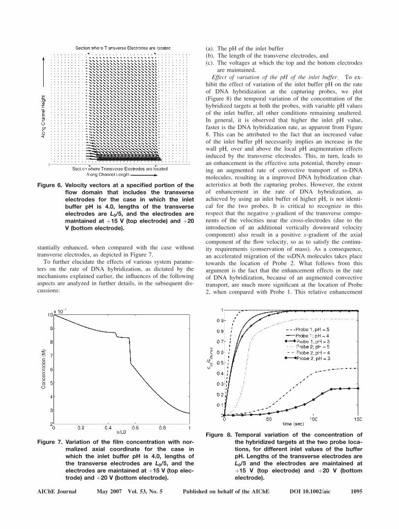
stantially enhanced, when compared with the case withouttransverse electrodes, as depicted in Figure 7.
To further elucidate the effects of various system parame-ters on the rate of DNA hybridization, as dictated by themechanisms explained earlier, the influences of the followingaspects are analyzed in further details, in the subsequent dis-cussions:
(a). The pH of the inlet buffer(b). The length of the transverse electrodes, and(c). The voltages at which the top and the bottom electrodes
are maintained.Effect of variation of the pH of the inlet buffer. To ex-
hibit the effect of variation of the inlet buffer pH on the rateof DNA hybridization at the capturing probes, we plot(Figure 8) the temporal variation of the concentration of thehybridized targets at both the probes, with variable pH valuesof the inlet buffer, all other conditions remaining unaltered.In general, it is observed that higher the inlet pH value,faster is the DNA hybridization rate, as apparent from Figure8. This can be attributed to the fact that an increased valueof the inlet buffer pH necessarily implies an increase in thewall pH, over and above the local pH augmentation effectsinduced by the transverse electrodes. This, in turn, leads toan enhancement in the effective zeta potential, thereby ensur-ing an augmented rate of convective transport of ss-DNAmolecules, resulting in a improved DNA hybridization char-acteristics at both the capturing probes. However, the extentof enhancement in the rate of DNA hybridization, asachieved by using an inlet buffer of higher pH, is not identi-cal for the two probes. It is critical to recognize in thisrespect that the negative y-gradient of the transverse compo-nents of the velocities near the cross-electrodes (due to theintroduction of an additional vertically downward velocitycomponent) also result in a positive x-gradient of the axialcomponent of the flow velocity, so as to satisfy the continu-ity requirements (conservation of mass). As a consequence,an accelerated migration of the ssDNA molecules takes placetowards the location of Probe 2. What follows from thisargument is the fact that the enhancement effects in the rateof DNA hybridization, because of an augmented convectivetransport, are much more significant at the location of Probe2, when compared with Probe 1. This relative enhancement
Figure 7. Variation of the film concentration with nor-malized axial coordinate for the case inwhich the inlet buffer pH is 4.0, lengths ofthe transverse electrodes are L0/5, and theelectrodes are maintained at þ15 V (top elec-trode) and þ20 V (bottom electrode).
Figure 8. Temporal variation of the concentration ofthe hybridized targets at the two probe loca-tions, for different inlet values of the bufferpH. Lengths of the transverse electrodes areL0/5 and the electrodes are maintained atþ15 V (top electrode) and þ20 V (bottomelectrode).
Figure 6. Velocity vectors at a specified portion of theflow domain that includes the transverseelectrodes for the case in which the inletbuffer pH is 4.0, lengths of the transverseelectrodes are L0/5, and the electrodes aremaintained at þ15 V (top electrode) and þ20V (bottom electrode).
AIChE Journal May 2007 Vol. 53, No. 5 Published on behalf of the AIChE DOI 10.1002/aic 1095

is only possible because of the local increments in the mag-nitudes of the wall zeta potentials, on account of the trans-verse electrode effects.
Effect of the Variation of the Length of the TransverseElectrodes. To analyze the effects of variation of the lengthof the transverse electrodes on the rate of DNA hybridizationat the probes, we plot Figure 9, which depicts the temporalvariation of the concentration of the hybridized targets fordifferent lengths of the transverse electrodes (i.e., differentvalues of LE), keeping all other conditions unaltered. Byaltering the lengths of the transverse electrodes, the portionof the channel length over which the zeta potential is modi-fied due to the ‘field effect’ is effectively varied. From Fig-ure 9, it is evident that the rate of DNA hybridization atProbe 1, as indicated by the temporal variation of the con-centration of the hybridized targets at that location, is insen-sitive to the changes in lengths of the transverse electrodes,because of the fact that the Probe 1 is located upstream rela-tive to the transverse electrodes, and therefore carries no in-formation of alteration of the wall zeta potential by virtue oftheir presence. At the location of Probe 2, however, influenceof upstream transverse electrodes can be strongly felt. Ingeneral, it is revealed that longer the transverse electrodes,longer is the portion of the channel over which the ‘fieldeffect,’ causing an enhanced localized axial transport and aneffective ‘push’ towards the bottom wall leading to destruc-tion of depletion layer, on account of enhanced zeta poten-tial, is felt. The result is the improvement in the rate of DNAhybridization at Probe 2. However, it needs to be remem-bered at this point that the length of transverse electrodescannot be indiscriminately increased so as to exploit a maxi-mum advantage of the consequent augmentation in the rateof convective transport, mainly because of the technologicalconstraints associated with the placement of the DNA probesdevoid of any direct interference with the wall electrodes.
Effect of the Variation of the Voltages of the TransverseElectrodes. To exhibit the effect of the variation of voltagesat the transverse electrodes on the rate of DNA hybridization,we plot Figure 10, which depicts the temporal variation ofthe concentration of the hybridized targets at the two probelocations, for different values of the transverse electrode vol-tages, all other conditions remaining unaltered. To demon-strate these aspects, following three cases are considered: (a)Case A: no transverse electrode, (b) Case B: þ15V andþ20V at the top and the bottom electrodes, respectively, (c)Case C: þ15V and þ65V at the top and the bottom electro-des, respectively. In each of three cases, the buffer pH istaken to be 4 and the transverse electrodes for Cases B andC are taken to be of length L0/5. As expected, the hybridiza-tion pattern at Probe 1 is insensitive to the variationsamongst the three different cases, since the Probe 1 islocated upstream to the transverse electrodes. However, atthe location of Probe 2, effects of voltages of the transverseelectrodes are strongly felt. Higher the electrode potentials,more significant is the corresponding enhancement in thewall zeta potential, and stronger is the augmentation in therate of electrokinetic convective transport and the effectivedownward ‘push,’ leading to a richer supply of DNA mole-cules to the downstream probe location (i.e., Probe 2),thereby ensuring improved hybridization rates. As a result,for higher values of the transverse electrode voltages, anearly uniform rate of DNA hybridization can effectively beachieved at the different capturing probe locations, therebyvirtually nullifying the counteracting effects of a continuousremoval of the ss-DNA molecules from the bulk because ofthe specific and nonspecific hybridization effects at the fur-
Figure 9. Temporal variation of the concentration ofthe hybridized targets at the two capturingprobe locations, for different values of thetransverse electrodes lengths.
The electrodes are maintained at þ15 V (top electrode)and þ20 V (bottom electrode), and the inlet buffer pH istaken to be 4.
Figure 10. Temporal variation of the concentration ofthe hybridized targets at the two capturingprobe locations, for the following cases,Case A: no transverse electrodes; Case B:the transverse electrodes are maintained atþ20 V (the bottom electrode) and þ15 V(top electrode); and Case C: the transverseelectrodes are maintained at þ65 V (thebottom electrode) and þ15 V (top elec-trode).
Lengths of the transverse electrodes are L0/5 and the inletbuffer pH is taken to be 4.
1096 DOI 10.1002/aic Published on behalf of the AIChE May 2007 Vol. 53, No. 5 AIChE Journal

ther upstream sections. Such a uniform concentration distribu-tion is often useful for the cases, in which one employs a sin-gle nucleic acid hybridization system, to accomplish multiplediagnostic purposes. However, it needs to be remembered herethat the transverse electrode voltages cannot be incremented atwill, in an effort to obtain the favorable effects mentioned asearlier. This is because of the fact that the resultant electricfield needs to be constrained within stringent limits in practice,so as to ensure that the associated Joule heating effects are notstrong enough to result in a denaturation of the thermallylabile DNA samples. We present a critical assessment of thisaspect in the subsequent subsection.
Other than the effects of these three significant operatingparameters mentioned as earlier, it is important to recognizehere that the channel height is also intuitively expected tobear significant consequences on the rate of DNA hybridiza-tion. However, it has already been demonstrated in the litera-ture that the effect of the channel height on the rate of DNAhybridization becomes important35 only if the transport ispredominantly pressure-driven, since in such a case the ve-locity variations are strongly dependent on the transversecoordinates. On the other hand, for a pure electro-osmoticflow field, as considered in this study, the axial velocity com-ponents remain virtually uniform over the channel cross sec-tions, provided that the channel dimensions are large enough(typically of the order of 1 mm or more) to ensure nonover-lapped EDL fields, so that the channel height does not play acritical role in influencing the rate of DNA hybridizationunder these conditions. However, in case of nanochannels,such effects can be of critical importance in determining thenet rate of macromolecular transport and hybridization. Forinstance, in case of nanochannels, the net rate of macromo-lecular transport may be significantly reduced because of ahindered diffusive transport originated out of the confinementeffects. Narrower the channel, stronger becomes this effect.However, since the present study is only confined to the elec-tro-osmotically-driven DNA hybridization in microfluidicchannels, analysis of the height-dependent macromoleculartransport in nanochannels falls beyond the present scope, andaccordingly, is not discussed here.
Limitations in Employing Transverse Electric Fields forEnhancing the Rate DNA Hybridization. ‘Melting’ or‘denaturation’ of DNA is characterized by the separation oftwo DNA strands from an existing hybridized state. Thissplitting occurs at the melting temperature, Tm, defined asthe temperature at which 50% of the oligonucleotides andtheir perfect complements are in duplex. To avoid problemslike inappropriate duplex formation, primer mismatch etc.,the hybridization is typically carried out 58 � 108C belowTm. Hence it is important that the temperature rise due toJoule heating during hybridization is not more than around58C. This, in turn, imposes serious restraints to the upperlimit of the electric field that can be employed to actuate theelectrokinetic flows in the DNA hybridization assays. Toassess this issue critically, it is imperative to obtain the tem-perature distributions along the channel bottom wall, for theCases A, B, and C mentioned in the previous subsection,which are depicted in Figures 11a–c. For Case A (no trans-verse electrodes), the maximum temperature rise is found tobe well within the permissible limits prescribed earlier,thereby avoiding any thermal denaturation of the hybridized
DNA samples. So far as the Case B is concerned, it isrevealed that the axial temperature profile along the bottomwall, at a given instant of time, exhibits the trend of an ab-rupt rise near the locations of placement of the transverseelectrodes. However, for this case too, the maximum temper-ature rise at any portion of the channel wall is safely withinthe permissible limits to avoid DNA melting. Therefore, so
Figure 11. Temporal variation of temperature along thebottom wall of the channel in the axial direc-tion, for (a) Case A, (b) Case B, and (c) Case C.
Detailed particulars of these three cases are mentioned inthe caption of Figure 7.
AIChE Journal May 2007 Vol. 53, No. 5 Published on behalf of the AIChE DOI 10.1002/aic 1097

far as the DNA hybridization is concerned, the arrangementfor Case B (with transverse electrodes) turns out to be morefavorable than the same employed for Case A (without trans-verse electrodes). However, for Case C, it is found that thelocalized temperature rise on account of the placement oftransverse electrodes turns out to be in the tune of 358C(refer to Figure 11c), which is much above the safe permissi-ble limit of about 58C. This can be attributed to the existenceof much stronger localized transverse potential gradients inCase C, when compared with that for the Cases A and B.For a physical assessment of the prevailing situation, a scal-ing argument in favor of such behaviour can be put forward,by noting that the maximum temperature rise, DT, can beestimated as
DT � sðE2x þ E2
yÞDtrCp
(37)
where Dt is the time elapsed. In the earlier expression,Ey � DVT
H , where DVT is the potential difference between thetransverse electrodes. Clearly, DVT for Case C (i.e., 40 V)turns out to be much higher than that for Case B (i.e., 5 V),resulting in much greater temperature increments in the for-mer case than the later. As a consequence, although the rateof DNA hybridization is clearly more favorable in Case Cthan in Case B, the former case does not offer with a techno-logically viable option for augmenting the hybridization per-formance in a DNA assay.
Conclusions
The present model discusses a novel approach to ensure afaster rate of DNA hybridization, by creating a localized pHgradient on employment of local transverse electric fieldsover selected portions of the channel length. Arrangement ofsuch transverse electrodes is primarily motivated because ofthe following reason. A progressive depletion of the ss-DNAmolecules from the bulk (owing to nonspecific adsorptionand 3D hybridization at the probes that are located at furtherupstream sections), during their transport through the micro-channel, is likely to result in a reduced rate of DNA hybrid-ization at channel sections that are located further down-stream. However, on employment of transverse electrodepairs, localized enhancements in the wall zeta potential canbe achieved, which in turn, can promote a stronger convec-tive transport, and accordingly, a faster rate of DNA hybrid-ization can be achieved at capturing probes that are locatedfurther downstream relative to the channel inlet section.However, strength of the transverse electric field cannot beselected at will, but needs to be constrained within permissi-ble limits, so as to ensure that no further thermal denatura-tion of the hybridized DNA molecules takes place. The pres-ent model provides with a scientific guideline for solution ofthe resultant optimization problem, so as to achieve the fast-est rate of DNA hybridization without violating the upperlimits of temperature rise that can be allowed in practice.
Literature Cited
1. Chan V, Graves DJ, McKenzie SE. The biophysics of DNA hybridiza-tion with immobilized oligonucleotide probes. Biophys J. 1995;69:2243–2255.
2. Axelrod D, Wang MD. Reduction-of-dimensionality kinetics at reac-tion-limited cell surface receptors. Biophys J. 1994;66:588–600.
3. Zeng J, Almadidy A, Watterson J, Krull UJ. Interfacial hybridizationkinetics of oligonucleotides immobilized onto fused silica surfaces.Sens Actuators B. 2003;90:68–75.
4. Erickson D, Li D, Krull UJ. Modelling of DNA hybridizationkinetics for spatially resolved biochips. Anal Biochem. 2003;317:186–200.
5. Das S, Das T, Chakraborty S. Modeling of coupled momentum, heatand solute Transport during DNA hybridization in a microchannel inpresence of electro-osmotic effects and axial pressure gradients.Microfluidics Nanofluidics. 2006;2:37–49.
6. Hitt DL, McGarry M. Numerical simulations of laminar mixing sur-faces in pulsatile microchannel flows. Math Comput Simul. 2004;65:399–416.
7. Glasgow I, Aubry N. Enhancement of microfluidic mixing usingtime pulsing. Lab Chip. 2003;3:114–120.
8. Glasgow I, Batton J, Aubry N. Electroosmotic mixing in microchan-nels. Lab Chip. 2004;4:558–562.
9. Liu RH, Stremler MA, Sharp KV, Olsen MG, Santiago JG, AdrianRJ, Aref H, Beebe DJ. Passive mixing in a three-dimensional ser-pentine microchannel. J Microelectromech Syst. 2000;9:190–207.
10. Xia HM, Wan SYM, Shu C, Chew YT. Chaotic micromixers usingtwo-layer crossing channels to exhibit fast mixing at low Reynoldsnumbers. Lab Chip. 2005;5:748–755.
11. Johnson TJ, Ross D, Locascio LE. Rapid microfluidic mixing. AnalChem. 2002;74:45–51.
12. Ajdari A. Generation of transverse fluid currents and forces by anelectric field: electro-osmosis on charge-modulated and undulatedsurfaces. Phy Rev E. 1996;53:4996–5005.
13. Kuksenok O, Yeomans JM, Balazs AC. Using patterned substratesto promote mixing in microchannels. Phys Rev E. 2002;65:031502.
14. Zhang J, He G, Liu F. Electro-osmotic flow and mixing in heteroge-neous microchannels. Phys Rev E. 2006;73:056305.
15. Tseng WL, Hsieh MM, Wang SJ, Chang HT. Effect of ionicstrength, pH and polymer concentration on the separation of DNAfragments in the presence of electroosmotic flow. J Chromatogr A.2000;894:219–230.
16. Peng XY, Li PCH. A three-dimensional flow control concept forsingle-cell experiments on a microchip. II. Fluorescein Diacetatemetabolism and calcium mobilization in a single yeast cell asstimulated by glucose and pH changes. Anal Chem. 2004;76:5282–5292.
17. Righetti P, Bossi A. Isoelectric focusing of proteins and peptides ingel slabs and in capillaries. Anal Chim Acta. 1998;372:1–19.
18. Lee GB, Fu LM, Lee CY, Yang RJ. Dispersion control in microflui-dic chips by localized z potential variation using the field effect.Electrophoresis. 2004;25:1879–1887.
19. Molloy RF, Leighton DT Jr. Binary oscillatory cross-flow elec-trophoresis: theory and experiments. J Pharm Sci. 1998;87:1270–1281.
20. Chen Z, Chauhan A. Taylor dispersion in cyclic electric field-flowfractionation. Phys Fluid. 2006;18:067105–067116.
21. Chen Z, Chauhan A. DNA separation by EFFF in a microchannel.J Colloid Interface Science. 2005;285:834–844.
22. Tang GY, Yang C, Chai JC, Gong HQ. Joule heating effect on elec-troosmotic flow and mass species transport in a microcapillary. Int.J. Heat Mass Trans. 2004;47:215–227.
23. Sonuart TL, Baygents JC. Electrically-driven fluid motion in chan-nelswith streamwise gradients of the electrical conductivity. ColloidSurf A. 2001;195:59–75.
24. Dwyer JD, Bloomfield VA. Brownian dynamics simulation of probediffusion in DNA: effects of probe size, charge and DNA concentra-tion. Biophys Chem. 1995;57:55–64.
25. Phillies GDJ. Universal scaling equation for self-diffusion by macro-molecules in solution. Macromolecules. 1986;19:2367–2376.
26. Tracy MA, Pecora R. Macromolecular synthesis, characterizationand dynamics of a rod/sphere composite Liquid. Macromolecules.1992;25:337–354.
27. Wattenbarger MR, Bloomfield VA, Bu Z, Russo P. Tracer diffusionof proteins in DNA solutions. Macromolecules. 1992;25:5263–5265.
28. Carre A, Lacarriere V, Birch W. Molecular interactions betweenDNA and an aminated glass substrate. J Colloid Interface Sci.2003;260:49–55.
1098 DOI 10.1002/aic Published on behalf of the AIChE May 2007 Vol. 53, No. 5 AIChE Journal

29. Parks GA. Isoelectric points of solid oxides solid hydroxides andaqueous hydroxo complex systems. Chem Rev. 1965;65:177–198.
30. Carre A, Roger F, Varinot C. Study of acid/base properties of oxide, oxideglass and glass-ceramic surfaces. J Colloid Interface Sci. 1992;154:174–183.
31. Kirby BJ, Hasselbrink EF. Jr. The z potential of microfluidic sub-strates. I. Theory, experimental techniques, and effects on separa-tions. Electrophoresis. 2004;25:187–202.
32. Hayes MA, Ewing AG. Electroosmotic flow control and monitoringwith an applied radial voltage for capillary zone electrophoresis.Anal Chem. 1992;64:512–516.
33. Lee CS, McManigill D, Wu CT, Patel B. Factors affecting directcontrol of electroosmosis using an external electric field in capillaryelectrophoresis. Anal Chem. 1991;63:1519–1523.
34. Wu HY, Liu CH. A novel electrokinetic micromixer. Sens ActuatorsA. 2005;118:107–115.
35. Kim JH, Marafie A, Jia X, Zoval JV, Madou M. Characterization ofDNA hybridization kinetics in a microfluidic flow channel. SensActuators B. 2006;113:281–289.
Manuscript received July 6, 2006, and revision received Jan. 16, 2007.
AIChE Journal May 2007 Vol. 53, No. 5 Published on behalf of the AIChE DOI 10.1002/aic 1099