catalytic reforming of dimethyl ether in microchannels
TRANSCRIPT

Contents lists available at ScienceDirect
Catalysis Today
journal homepage: www.elsevier.com/locate/cattod
Catalytic reforming of dimethyl ether in microchannels
Cristian Ledesmaa, Eduardo Lópeza,b, Trifon Trifonovc, Ángel Rodríguezd, Jordi Llorcaa,c,e,⁎
a Institute of Energy Technologies, Universitat Politècnica de Catalunya, EEBE, Eduard Maristany 16, 08019 Barcelona, Spainb Planta Piloto de Ingeniería Química, UNS, CONICET, Camino La Carrindanga km 7, 8000 Bahía Blanca, Argentinac Barcelona Research Center in Multiscale Science and Engineering, Universitat Politècnica de Catalunya, EEBE, Eduard Maristany 16, 08019 Barcelona, Spaind Department of Electronic Engineering, Universitat Politècnica de Catalunya, Campus Nord, Jordi Girona 1-3, 08034 Barcelona, Spaine Department of Chemical Engineering, Universitat Politècnica de Catalunya, EEBE, Eduard Maristany 16, 08019 Barcelona, Spain
A R T I C L E I N F O
Keywords:HydrogenDimethyl etherSteam reformingAutothermal reformingMicroreactorMicromonolith
A B S T R A C T
The steam reforming and oxidative steam reforming of dimethyl ether (DME) were tested at 573–773 K over aCuZn/ZrO2 catalyst in microreactors with three different types of channels: ceramic square channels with sidelengths of 900 and 400 μm, and silicon microchannels of 2 μm of diameter. The channels were first coated withZrOCl2 (ceramic channels) or Zr(i-PrO)4 (silicon microchannels) and calcined at 773 K for 2 h to obtain ahomogeneous and well-adhered ZrO2 layer, as determined by SEM, and then Cu and Zn (Cu:Zn= 1:1M, 20 wt%total metal) were co-impregnated. Operation at highly reduced residence time (10−3 s) while achieving hy-drogen yields similar to those recorded over the ceramic channels was possible for the silicon microchannels dueto the three orders of magnitude increased contact area. In addition, the amount of catalyst used for coating thesilicon microchannels was two orders of magnitude lower with respect to the conventional ceramic channels.Outstanding specific hydrogen production rates of 0.9 LN of H2 per min and cm3 of reactor volume were achievedas well as stable operation for 80 h, which demonstrates the feasibility of using on-site, on-demand hydrogengeneration from DME for portable fuel cell applications.
1. Introduction
Dimethyl ether (DME) can be used as a high-density hydrogencarrier facilitating the operation of fuel reformers for feeding low-temperature fuel cells in portable applications due to its low evapora-tion temperature and its corrosion-safe and easy handling character.The reforming of DME represents an excellent way to feed fuel cells insmall environments because DME can be easily stored in liquid form atlow pressure (≥0.51MPa bar at 298 K) and then transformed into gasby a simple pressure relief valve, thus avoiding the need of investingenergy for evaporation, as it occurs with other common liquids used foron-board hydrogen generation such as methanol, ethanol, gasoline ordiesel [1,2]. In addition, DME can be obtained from almost any car-bonaceous feedstock by first generating synthesis gas and then allowingsynthesis gas to react over a catalyst [3]. Given the absence of CeCbonds in DME, which can only be cleaved at high temperatures, thecatalytic reforming of DME can be carried out at moderate tempera-tures (573–873 K). Different catalytic reforming technologies can beapplied to generate hydrogen from DME (Eq. (1)), being steam re-forming (n=0) and oxidative steam reforming (0 < n < 3) the mostappropriate to optimize a trade-off between energy input, hydrogen
yield, operation simplicity, and catalyst stability [4–7].
CH3OCH3+ (3-n) H2O+n/2 O2→ (6-n) H2+ 2 CO2 (1)
The catalytic reforming of DME at moderate temperature consists oftwo consecutive reactions; first, DME is hydrolyzed to methanol over anacid catalyst, and then methanol is subsequently transformed into amixture of H2 and COx over a metal function with the participation ofthe water gas shift reaction (WGS). Acidity of the catalyst is supplied bythe support, usually γ-Al2O3, ZrO2, WO3/ZrO2 and zeolites such as ZSM-5 [8–23], but also tungstosilicoheteropolyacids, Ga2O3/TiO2 and Mo2C[24–26], whereas the metal function is usually based on Cu (normallyCuZn or Cu/CeO2) [27–39] or Pd (Pd or PdZn) [40–43], although theuse of other metals such as Ni, Pt, Rh, Ru and Au [44–53] and spineloxides such as CuFe2O4 have also been described in the literature[54–65]. A proper balance between the metallic and the acid functionsis required to guarantee a high hydrogen yield and catalyst stability.Not only the acid amount, but also the acid strength and the type ofacid-site definitely affect the steam reforming and hydrolysis activity[10,33,37]. The most used metal for DME steam reforming is copper (asit is the most used for methanol reforming). The interaction of Cu withthe support and the distribution of copper species (Cu metal vs. Cu+)
https://doi.org/10.1016/j.cattod.2018.03.011Received 16 January 2018; Received in revised form 3 March 2018; Accepted 8 March 2018
⁎ Corresponding author at: Institute of Energy Technologies, Universitat Politècnica de Catalunya, EEBE, Eduard Maristany 16, 08019 Barcelona, Spain.E-mail address: [email protected] (J. Llorca).
Catalysis Today xxx (xxxx) xxx–xxx
0920-5861/ © 2018 Elsevier B.V. All rights reserved.
Please cite this article as: Ledesma, C., Catalysis Today (2018), https://doi.org/10.1016/j.cattod.2018.03.011

play a determinant role for DME reforming [30,66]. Since Cu nano-particles tend to sinter under DME reforming conditions Zn is usuallyadded to ensure a robust catalyst [16,30,35–37,46,66–68]. Also, theaddition of alkaline elements and alkaline earth metal oxides in thecatalyst formulation has been described to have a positive effect, eitherby modifying the acidity of the support and thus suppressing the for-mation of undesired hydrocarbons, or by changing the reducibility ofthe metal function of the catalyst [18,37,53].
For a portable, on-demand fuel reformer, the advantage of oxidativesteam reforming over steam reforming is the energy balance of thesystem. Whereas steam reforming is an endothermic process(ΔH°∼ 124 kJ/mol), oxidative steam reforming can be carried outunder autothermal conditions at the expense of hydrogen yield[4,41,50,55,68]. Both the catalytic steam reforming and catalytic oxi-dative steam reforming of DME have been widely described in the lit-erature. Most of these studies have been addressed towards the for-mulation of active, selective and stable catalysts and, for practicalreasons, powdered catalysts have been generally used. As an additionalstep in catalyst implementation for real applications a few works havebeen carried out over catalytic cordierite honeycombs[21,41,42,66–72] as well as microreactors and foams [27,73–78]. Herewe extend these studies towards process intensification in DME fuelreformers by using catalytic microstructures containing channels withsmaller dimensions. In particular, we study the catalytic performance ofcordierite honeycombs with channels of side lengths of 900 and 400 μmand silicon microhoneycombs with microchannels of only 2 μm indiameter coated with CuZn/ZrO2. Lowering the dimensions of the mi-crochannels has a strong effect on the geometric surface area exposed toreactants, which in turn has a dramatic effect on the yield of hydrogenobtained calculated on a volumetric basis [79,80]. Moreover, mass andheat transfer are enhanced and less amount of catalyst is required whendecreasing the diameter of the microchannels, in particular for the si-licon microhoneycombs.
2. Experimental methods
2.1. Preparation of the catalytic structures
2.1.1. Conventional catalytic honeycombsConventional cordierite honeycomb structures of 400 and 900 cpsi
(cells per square inch) with square channels with side lengths of 900and 400 μm, respectively, were first washcoated with an aqueous so-lution of ZrOCl2·8 H2O at 353 K under continuous axial rotation andcalcined in air at 773 K for 2 h to obtain a well-adhered layer of ZrO2
[68]. Then, Cu and Zn were incorporated by a single-step incipientwetness impregnation from an ethanolic solution of Cu(NO3)2·3H2Oand Zn(NO3)2·6H2O (Cu:Zn= 1:1M, 20 wt% total metal) at roomtemperature. The resulting catalytic honeycombs were calcined in air at773 K for 5 h. The acidity values calculated from NH3-TPD were0.8 mmolNH3/gcatalyst. A catalyst loss below 5wt% was measured duringadherence tests in ultrasounds at 40 kHz for 30min. Honeycombswashcoated only with the ZrO2 support were used to conduct blankexperiments.
2.1.2. Silicon catalytic microhoneycombsSilicon microhoneycombs were prepared over< 100>n-type si-
licon wafers, with a resistivity of 2–6Ω cm. The channels were manu-factured by photoassisted electrochemical etching and subsequentopening of the pores from the back side following the methodologydescribed in [81]. Previously, the wafer surface was prestructured bylithography and etched with tetramethylammonium hydroxide (TMAH)to create a square array of inverted pyramids pointing toward the bulkof the wafer and defining the positions of channel growth. The elec-trochemical etching was carried out at 288 K at a constant anodic po-tential of 2 V in 5 wt% HF solution using an array of LEDs with an 880-nm peak emission wavelength. After the electrochemical etching, thewafers were oxidized in O2 at 1373 K for 30min, the oxide layer on thebackside was removed, and the remaining backside silicon was etchedoff in 25 wt% TMAH solution at 358 K until the pore tips were reached.The resulting structures were silicon wafers with a thickness of 0.2mm
Fig. 1. A) Cordierite honeycomb piece of 900 cpsi (photograph and scheme) coated with CuZn/ZrO2 catalyst. B) Stainless steel microreactor used to test the catalytic cordieritehoneycomb structures. C) and D) SEM images of the microchannels of the silicon micromonoliths prepared in this work.
C. Ledesma et al. Catalysis Today xxx (xxxx) xxx–xxx
2

and with straight microchannels of 2 μm in diameter arranged in asquare lattice with a periodicity of 3 μm (Fig. 1C and D), which meansca. 107 microchannels/cm2 and an open frontal area of 35%. An in-significant pressure drop of less than 0.01 bar was measured with ni-trogen flowing at 100mL/min and room temperature. Subsequently,the microchannels were first filled with Zr(i-PrO)4 by applying a pres-sure gradient of ca. 100 kPa and calcined at 773 K for 2 h to obtain ahomogeneous and well-adhered ZrO2 layer onto the microchannelswalls, and then Cu and Zn (Cu:Zn= 1:1M) were co-impregnated fol-lowing the same procedure explained above for the conventional cat-alytic honeycombs. This methodology is based on previous studieswhere catalytic layers of Co/ZnO, RhPd/CeO2 and Au/TiO2 were suc-cessfully deposited in silicon microchannels of 3–4 μm in diameter toperform the reforming of ethanol [81–83] and the preferential oxida-tion of carbon monoxide [84].
2.2. Characterization techniques
Powder X-ray diffraction (XRD) was carried out with a Bruker D8instrument equipped with a Cu target at a step width of 0.02° and bycounting 1 s at each step. Scanning electron microscopy (SEM) imageswere recorded at 5 kV using a Neon40 Crossbeam Station (Zeiss) in-strument equipped with a field emission source. Microstructural char-acterization by high-resolution transmission electron microscopy(HRTEM) was carried out at 200 kV with a JEOL JEM-2010F electronmicroscope equipped with a field emission gun. X-ray photoelectronspectroscopy (XPS) was performed with a SPECS system using an Al X-ray source (150W) and a 9-channel Phoibos detector at a pressure
below 10−6 Pa. Quantification was carried out using Shirley baselinesand Gaussian–Lorentzian lineshapes.
2.3. Catalytic tests
The cordierite honeycombs were cut into pieces of 20mmwidth× 23mm long×2mm height to fit into the microreactor usedfor the experiments (Fig. 1A). The microreactor was built in stainlesssteel and contained a reaction chamber equipped with two collectorsfor a proper gas distribution (Fig. 1B). Four heating cartridges wereallocated alternately for a homogeneous temperature distribution and athermocouple was placed at the center of the housing block (Fig. 1B).The silicon microhoneycomb wafer was cut with a laser into a diskmeasuring 8mm in diameter and glued with epoxy into a stainless steelwasher, which was sealed into a stainless steel tubular reactor andplaced inside a furnace. The flowrates of DME and O2 were adjustedwith mass flow controllers and H2O was dosed using a HPLC KnauerSmartline 100 pump. The effluent of the reactor was monitored on linewith an Agilent 3000A micro-GC equipped with PLOT U, Stabilwax and5 Å Molsieve columns for a complete analysis. Carbon balance closurecalculations were always within experimental error (5%). The catalyticdevices were first activated with a 10% H2/Ar mixture at 573 K for 2 h.Then the reaction mixture for DME steam reforming was introduced atthis temperature, with a DME:H2O molar ratio of 1:6 (S/C= 3). Thereaction was followed from 573 to 773 K at atmospheric pressure.Oxidative steam reforming was performed at 773 K using a S/C ratio of3 and a O2/DME ratio of 0.5. DME conversion (%) is defined asDMEconv= 100nDME,conv/2nDME,in, where nDME,conv represents the
Fig. 2. A) Low-magnification TEM image and XRD pattern of the ZrO2 support particles (■ tetragonal ZrO2, ● monoclinic ZrO2). B) HRTEM image of the support particles showing thecharacteristic lattice fringes of ZrO2. C) and D) HRTEM images of the CuZn/ZrO2 catalyst showing the occurrence of CuO and ZnO nanoparticles.
C. Ledesma et al. Catalysis Today xxx (xxxx) xxx–xxx
3

moles of DME converted measured as the sum of moles of CO2, CO, CH4
and CH3OH at the reactor outlet and nDME,in represents the moles ofDME at the reactor inlet. Selectivity to species i (%) is calculated as themoles of i divided by the total moles of products (H2, CO2, CO, CH4 andCH3OH), Si= 100ni/∑nT. Yield to species i (%) is calculated asYi=DMEconvSi/100.
3. Results and discussion
3.1. Characterization of the catalytic structures
The ZrO2 support and the CuZn/ZrO2 catalyst deposited on thecatalytic cordierite honeycombs walls were characterized by XRD, TEMand XPS after ripping some powder off the walls. A representative, low-magnification TEM image of the ZrO2 support particles is shown inFig. 2A. The sample is constituted by crystalline elongated platelets ofabout 40–100 nm in length. The XRD pattern (Fig. 2A) indicates thatmost of the support particles are tetragonal ZrO2, with a minor con-tribution of monoclinic ZrO2. This is in accordance with the calcinationtemperature used during the synthesis [66]. A high resolution TEMimage of the ZrO2 support particles is shown in Fig. 2B. The plateletsshow well-defined lattice fringes according to their crystalline nature,with crystallographic planes at 3.0 and 2.6 Å, which correspond well tothe (101) and (110) planes of tetragonal ZrO2. Fig. 2C and D showrepresentative TEM images of the CuZn/ZrO2 catalyst prepared by co-impregnating the corresponding Cu and Zn nitrates over the preformedZrO2 support particles. In addition to the elongated platelets of the ZrO2
support, the occurrence of much smaller nanoparticles of about 6–8 nmis clearly seen. An accurate analysis of their lattice fringes observedunder HRTEM reveals that they correspond to an intimate mixture ofCuO and ZnO nanoparticles. All the nanoparticles analyzed show latticefringes corresponding to CuO or ZnO. As an example, the crystal-lographic planes at 1.8 Å of the nanoparticle shown in Fig. 2D are as-cribed to the (202) planes of CuO, and those at 2.8 Å are ascribed to the(100) crystallographic planes of ZnO. It should be highlighted that theCuO and ZnO phases appear well mixed and in a narrow size dis-tribution. The XPS surface analysis of the CuZn/ZrO2 catalyst shows aCu/Zn atomic ratio of 0.87 and a (Cu+Zn)/Zr atomic ratio of 0.41,thus indicating an excellent and homogeneous distribution of both Cuand Zn, in accordance to the HRTEM results.
The characterization of the CuZn/ZrO2 catalyst inside the siliconmicrochannels was challenging given the small dimensions of the mi-crochannels and the low catalyst loading. For a proper characterization,one of the as-prepared catalytic silicon microhoneycombs was cut andthe vertical cross sections of the catalytic microchannels exposed werestudied by SEM. Fig. 3 shows a representative view of the catalytic layeron the silicon microchannels. The same area is shown recorded bysecondary electrons (Fig. 3A) and backscattered electrons (Fig. 3B). Ontop the silicon structure a well-developed layer of SiO2 of about 200 nmin thickness is observed (which was the result of the oxidation treat-ment at 1373 K for 30min during the preparation of the silicon mi-crochannels, as explained in Section 2.1.2) and, on top of it, a layer ofthe ZrO2 porous support of about 80–100 nm in thickness is recognized.The homogeneity and constant thickness of the ZrO2 support layer areremarkable. In addition, spherical particles are clearly visible on theZrO2 layer; their EDX analyses show the common occurrence of Cu andZn in all of them. Therefore, it can be assumed that similar catalystarchitectures are present in the CuZn/ZrO2 catalytic layers of the cor-dierite honeycombs and of the silicon microchannels.
3.2. DME steam reforming and oxidative steam reforming
The steam reforming of DME was carried out over the three types ofcatalytic channels at a constant S/C value of 3 at 573, 623, 673, 723and 773 K and atmospheric pressure. The data reported here corre-sponds to steady-state values after 1 h of reaction; no deactivation was
observed for any experimental condition assayed. Fig. 4 shows the DMEconversion, product selectivity and product yield obtained at eachtemperature with the cordierite honeycomb structures of 900 cpsi withsquare channels with side length of 400 μm coated with the bare ZrO2
support (blank experiment) and with the CuZn/ZrO2 catalyst. In bothcases, the conversion of DME increased with temperature, as expectedfrom a thermodynamic point of view taking into account the en-dothermic character of the process. The main product obtained over theZrO2 support was methanol, in accordance to the first step of the re-action (the hydrolysis of dimethyl ether) and the acidic character ofZrO2. At high temperature, partial steam reforming of methanol into H2
and CO2 was observed, particularly at 723 and 773 K. In contrast, thereaction over the CuZn/ZrO2 catalyst yielded exclusively the reformingproducts at temperatures higher than 673 K (methanol was observed asan intermediate product only at lower temperature). This fact demon-strates the high activity of the CuZn phase for the steam reforming ofmethanol. At high temperatures, 723 and 773 K, minor amounts of COare measured in addition to the main products H2 and CO2. This isexplained taking into account the water gas shift equilibrium:H2O+CO⇄H2+CO2. In addition, traces of CH4 are also measured,probably as a result of the hydrogenation of COx.
Exactly the same trends were observed for the cordierite honeycomb
Fig. 3. SEM images recorded using secondary (A) and backscattered (B) electrons of thevertical cross section of an individual microchannel in the silicon microhoneycomb (seethe scheme shown in the inset in B). In addition to the Si walls of the silicon structure,layers of SiO2 and ZrO2 are clearly identified as well as Cu-Zn nanoparticles anchored onthe ZrO2 support.
Fig. 4. Product yield obtained with a 900 cpsi cordierite honeycomb loaded with ZrO2
and CuZn/ZrO2 under DME steam reforming conditions at different temperatures. S/C= 3, ƬSTP∼ 0.5 s, GHSV∼ 5·103 h−1. DME conversion corresponds to the height of thebar and product selectivity is represented by the area of each product inside each bar.
C. Ledesma et al. Catalysis Today xxx (xxxx) xxx–xxx
4
structures of 400 cpsi with square channels with side length of 900 μmin accordance to previous studies [68] and for the silicon micro-monoliths coated with the CuZn/ZrO2 catalyst. However, given thedifferences in their channel dimensions, the spatial conditions testedwere different; in particular, the contact time (ƬSTP) varied from 1msup to 1 s and the gas hourly space velocity (GHSV) varied from ap-proximately 103 to 105 h−1. Fig. 5 shows the production of hydrogen(NmL/min) under different DME load values for the three differentchannel geometries recorded at 773 K. It is remarkable that the hy-drogen production values adjust well to a straight line through theorigin, which means that the three channel geometries tested behavesimilarly in the range studied. This is a meaningful result which in-dicates that process intensification is plausible, even if the contact timeis varied by several orders of magnitude. Therefore, an accurate com-parison between the three channel geometries is not straightforwardand, for that reason, a specific volumetric normalized parameter will beused here, which is defined as the amount of hydrogen generated peramount of DME in the feed (valid in the range used of 0–5mLDME,g/min) for a given reactor volume: mLH2,g/(mLDME,g cm3
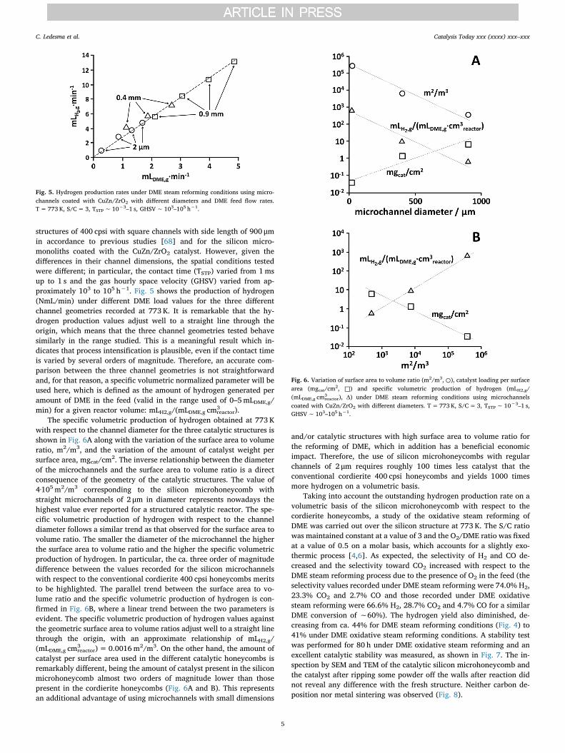
reactor).The specific volumetric production of hydrogen obtained at 773 K
with respect to the channel diameter for the three catalytic structures isshown in Fig. 6A along with the variation of the surface area to volumeratio, m2/m3, and the variation of the amount of catalyst weight persurface area, mgcat/cm2. The inverse relationship between the diameterof the microchannels and the surface area to volume ratio is a directconsequence of the geometry of the catalytic structures. The value of4·105 m2/m3 corresponding to the silicon microhoneycomb withstraight microchannels of 2 μm in diameter represents nowadays thehighest value ever reported for a structured catalytic reactor. The spe-cific volumetric production of hydrogen with respect to the channeldiameter follows a similar trend as that observed for the surface area tovolume ratio. The smaller the diameter of the microchannel the higherthe surface area to volume ratio and the higher the specific volumetricproduction of hydrogen. In particular, the ca. three order of magnitudedifference between the values recorded for the silicon microchannelswith respect to the conventional cordierite 400 cpsi honeycombs meritsto be highlighted. The parallel trend between the surface area to vo-lume ratio and the specific volumetric production of hydrogen is con-firmed in Fig. 6B, where a linear trend between the two parameters isevident. The specific volumetric production of hydrogen values againstthe geometric surface area to volume ratios adjust well to a straight linethrough the origin, with an approximate relationship of mLH2,g/(mLDME,g cm3
reactor)= 0.0016m2/m3. On the other hand, the amount ofcatalyst per surface area used in the different catalytic honeycombs isremarkably different, being the amount of catalyst present in the siliconmicrohoneycomb almost two orders of magnitude lower than thosepresent in the cordierite honeycombs (Fig. 6A and B). This representsan additional advantage of using microchannels with small dimensions
and/or catalytic structures with high surface area to volume ratio forthe reforming of DME, which in addition has a beneficial economicimpact. Therefore, the use of silicon microhoneycombs with regularchannels of 2 μm requires roughly 100 times less catalyst that theconventional cordierite 400 cpsi honeycombs and yields 1000 timesmore hydrogen on a volumetric basis.
Taking into account the outstanding hydrogen production rate on avolumetric basis of the silicon microhoneycomb with respect to thecordierite honeycombs, a study of the oxidative steam reforming ofDME was carried out over the silicon structure at 773 K. The S/C ratiowas maintained constant at a value of 3 and the O2/DME ratio was fixedat a value of 0.5 on a molar basis, which accounts for a slightly exo-thermic process [4,6]. As expected, the selectivity of H2 and CO de-creased and the selectivity toward CO2 increased with respect to theDME steam reforming process due to the presence of O2 in the feed (theselectivity values recorded under DME steam reforming were 74.0% H2,23.3% CO2 and 2.7% CO and those recorded under DME oxidativesteam reforming were 66.6% H2, 28.7% CO2 and 4.7% CO for a similarDME conversion of ∼60%). The hydrogen yield also diminished, de-creasing from ca. 44% for DME steam reforming conditions (Fig. 4) to41% under DME oxidative steam reforming conditions. A stability testwas performed for 80 h under DME oxidative steam reforming and anexcellent catalytic stability was measured, as shown in Fig. 7. The in-spection by SEM and TEM of the catalytic silicon microhoneycomb andthe catalyst after ripping some powder off the walls after reaction didnot reveal any difference with the fresh structure. Neither carbon de-position nor metal sintering was observed (Fig. 8).
Fig. 5. Hydrogen production rates under DME steam reforming conditions using micro-channels coated with CuZn/ZrO2 with different diameters and DME feed flow rates.T= 773 K, S/C=3, ƬSTP∼ 10−3–1 s, GHSV∼ 103–105 h−1.
Fig. 6. Variation of surface area to volume ratio (m2/m3, ○), catalyst loading per surfacearea (mgcat/cm2, □) and specific volumetric production of hydrogen (mLH2,g/(mLDME,g cm3
reactor), Δ) under DME steam reforming conditions using microchannelscoated with CuZn/ZrO2 with different diameters. T= 773 K, S/C=3, ƬSTP∼ 10−3–1 s,GHSV∼ 103–105 h−1.
C. Ledesma et al. Catalysis Today xxx (xxxx) xxx–xxx
5

4. Conclusions
Catalytic wall honeycombs consisting of ceramic cordierite channelswith side lengths of 900 and 400 μm and silicon disks containing ca. 107
microchannels of 2 μm of diameter per cm2 have been successfullycoated with a homogeneous layer of CuZn/ZrO2 catalyst by a two-stepprocess. First, a support layer of ZrO2 has been adhered onto thechannels walls, and then Cu and Zn have been co-impregnated. A thincatalyst layer of 80–100 nm in thickness has been grafted onto the si-licon microchannels, which has resulted in a two order of magnitudeless amount of catalyst per surface area with respect to the conventionalcordierite honeycombs (0.03 vs. 1.5–6mgcatalyst/cm2, respectively).Besides, given the small dimension of the silicon microchannels, the
surface area to volume ratio of the silicon disks has exceeded in variousorders of magnitude that of the conventional cordierite honeycombs(4·105 vs. 5·102–8·103m2/m3, respectively). As a direct consequence ofboth factors, the catalytic silicon microstructures have performed muchbetter in terms of specific hydrogen production rates in the steam re-forming of DME at 573–773 K (S/C=3, GHSV=103–105 h−1), withremarkable specific hydrogen production rates of 0.9 LN of H2 per minand cm3 of reactor volume. To improve the energy balance of thesystem, the oxidative steam reforming of DME has been also tested at773 K with O2/DME=0.5 over the silicon microchannels. It should bementioned that the energetic cost of preheating and evaporating thesurplus water used in our experiments (S/C= 3) should be consideredin conjunction with the conclusions arising from the reaction perfor-mance for the final selection of the optimum operational S/C value. Theimplementation of catalytic silicon microchannels for on-site, on-de-mand hydrogen generation from DME steam reforming and oxidativesteam reforming processes appears promising for portable fuel cellapplications.
Acknowledgments
This work has been funded by MINECO/FEDER project ENE2015-63969-R. JL is a Serra Húnter Fellow and is grateful to ICREA Academiaprogram. We are grateful to Pau Solano for technical assistance.
References
[1] D. Li, X. Li, J. Gong, Chem. Rev. 116 (2016) 11529–11653.[2] Z. Azizi, M. Rezaeimanesh, T. Tohidian, M.R. Rahimpour, Chem. Eng. Process. 82
(2014) 150–172.[3] J. Sun, G. Yang, Y. Yoneyama, N. Tsubaki, ACS Catal. 4 (2014) 3346–3356.[4] K. Faungnawakij, N. Viriya-Empikul, W. Tanthapanichakoon, Int. J. Hydrogen
Energy 36 (2011) 5865–5874.[5] T.A. Semelsberger, R.L. Borup, J. Power Sources 152 (2005) 87–96.[6] T.A. Semelsberger, R.L. Borup, J. Power Sources 155 (2006) 340–352.[7] K. Faungnawakij, R. Kikuchi, K. Eguchi, J. Power Sources 164 (2007) 73–79.[8] K. Takeishi, H. Suzuki, Appl. Catal. A: Gen. 260 (2004) 111–117.[9] T. Nishiguchi, K. Oka, T. Matsumoto, H. Kanai, K. Utani, S. Imamura, Appl. Catal. A:
Gen. 301 (2006) 66–74.[10] K. Faungnawakij, Y. Tanaka, N. Shimoda, T. Fukunaga, S. Kawashima, R. Kikuchi,
K. Eguchi, Appl. Catal. A: Gen. 304 (2006) 40–48.[11] T. Kawabata, H. Matsuoka, T. Shishido, D. Li, Y. Tian, T. Sano, K. Takehira, Appl.
Catal. A: Gen. 308 (2006) 82–90.[12] K. Oka, T. Nishiguchi, H. Kanai, K. Utani, S. Imamura, Appl. Catal. A: Gen. 309
(2006) 187–191.[13] T.A. Semelsberger, K.C. Ott, R.L. Borup, H.L. Greene, Appl. Catal. A: Gen. 309
(2006) 210–223.[14] K. Faungnawakij, R. Kikuchi, T. Matsui, T. Fukunaga, K. Eguchi, Appl. Catal. A:
Gen. 333 (2007) 114–121.[15] A.G. Gayubo, J. Vicente, J. Ereña, L. Oar-Arteta, M.J. Azkoiti, M. Olazar, J. Bilbao,
Appl. Catal. A: Gen. 483 (2014) 76–84.[16] Z. Sun, M. Meng, L. Zhang, Y. Zha, X. Zhou, Z. Jiang, S. Zhang, Y. Huang, Int. J.
Hydrogen Energy 37 (2012) 18860–18869.[17] J. Ereña, J. Vicente, A.T. Aguayo, A.G. Gayubo, M. Olazar, J. Bilbao, Int. J.
Hydrogen Energy 38 (2013) 10019–10028.[18] J. Vicente, A.G. Gayubo, J. Ereña, A.T. Aguayo, M. Olazar, J. Bilbao, Appl. Catal. B:
Environ. 130–131 (2013) 73–83.[19] X. Long, Q. Zhang, Z.T. Liu, P. Qi, J. Lu, Z.W. Liu, Appl. Catal. B: Environ. 134–135
(2013) 381–388.[20] D. Feng, Y. Wang, D. Wang, J. Wang, Chem. Eng. J. 146 (2009) 477–485.[21] C. Ledesma, J. Llorca, Chem. Eng. J. 154 (2009) 281–286.[22] J. Li, Q.J. Zhang, X. Long, P. Qi, Z.T. Liu, Z.W. Liu, Chem. Eng. J. 187 (2012)
299–305.[23] S. Zhou, K. Ma, Y. Tian, M. Meng, T. Ding, Y. Zha, T. Zhang, X. Li, RSC Adv. 6
(2016) 52411–52420.[24] V.V. Galvita, G.L. Semin, V.D. Belyaev, T.M. Yurieva, V.A. Sobyanin, Appl. Catal. A:
Gen. 216 (2001) 85–90.[25] T. Mathewa, Y. Yamada, A. Ueda, H. Shioyama, T. Kobayashi, C.S. Gopinath, Appl.
Catal. A: Gen. 300 (2006) 58–66.[26] F. Solymosi, R. Barthos, A. Kecskeméti, Appl. Catal. A: Gen. 350 (2008) 30–37.[27] R. Kousar, D.H. Kim, B.Y. Yu, H.P. Ha, S.H. Kim, J.Y. Byun, Appl. Catal. A: Gen.
423–424 (2012) 176–184.[28] S. Park, B. Choi, H. Kim, Y.J. Lee, Appl. Catal. A: Gen. 437–438 (2012) 173–183.[29] K. Takeishi, Y. Akaike, Appl. Catal. A: Gen. 510 (2016) 20–26.[30] X. Wang, K. Ma, L. Guo, Y. Tian, Q. Cheng, X. Bai, J. Huang, T. Ding, X. Li, Appl.
Catal. A: Gen. 540 (2017) 37–46.[31] X. Zhou, M. Meng, Z. Sun, Q. Li, Z. Jiang, Chem. Eng. J. 174 (2011) 400–407.
Fig. 7. Product selectivity and DME conversion during a stability test of the silicon mi-crohoneycomb loaded with CuZn/ZrO2 under DME oxidative steam reforming conditions.T= 773 K, S/C=3, O2/DME=0.5, ƬSTP∼ 1ms, GHSV∼ 105 h−1.
Fig. 8. SEM (A) and TEM (B) images of the catalytic silicon microhoneycomb loaded withthe CuZn/ZrO2 catalyst after a stability test under DME oxidative steam reforming con-ditions for 80 h.
C. Ledesma et al. Catalysis Today xxx (xxxx) xxx–xxx
6

[32] S.D. Badmaev, P.V. Snytnikov, Int. J. Hydrogen Energy 33 (2008) 3026–3030.[33] X. Wang, X. Pan, R. Lin, S. Kou, W. Zou, J.X. Ma, Int. J. Hydrogen Energy 35 (2010)
4060–4068.[34] P.V. Snytnikov, S.D. Badmaev, G.G. Volkova, D.I. Potemkin, M.M. Zyryanova,
V.D. Belyaev, V.A. Sobyanin, Int. J. Hydrogen Energy 37 (2012) 16388–16396.[35] L. Oar-Arteta, A. Remiro, J. Vicente, A.T. Aguayo, J. Bilbao, A.G. Gayubo, Fuel
Process. Technol. 126 (2014) 145–154.[36] L. Zhang, M. Meng, S. Zhou, Z. Sun, J. Zhang, Y. Xie, T. Hu, J. Power Sources 232
(2013) 286–296.[37] J. Ereña, J. Vicente, A.T. Aguayo, M. Olazar, J. Bilbao, A.G. Gayubo, Appl. Catal. B:
Environ. 142–143 (2013) 315–322.[38] Y. Zang, X. Dong, C. Wang, Chem. Eng. J. 313 (2017) 1583–1592.[39] S. Park, H. Kim, B. Choi, Catal. Today 164 (2011) 240–245.[40] H. Yoshida, N. Iwasa, H. Akamatsu, M. Arai, Int. J. Hydrogen Energy 40 (2015)
5624–5627.[41] M. Nilsson, K. Jansson, P. Jozsa, L.J. Pettersson, Appl. Catal. B: Environ. 86 (2009)
18–26.[42] C. Ledesma, U.S. Ozkan, J. Llorca, Appl. Catal. B: Environ. 101 (2011) 690–697.[43] E. Ramos, L. Davin, I. Angurell, C. Ledesma, J. Llorca, ChemCatChem 7 (2015)
2179–2187.[44] Q. Zhang, X. Li, K. Fujimoto, K. Asami, Appl. Catal. A: Gen. 288 (2005) 169–174.[45] N. Laosiripojana, S. Assabumrungrat, Appl. Catal. A: Gen. 320 (2007) 105–113.[46] T. Fukunaga, N. Ryumon, S. Shimazu, Appl. Catal. A: Gen. 348 (2008) 193–200.[47] A. Gazsi, I. Ugrai, F. Solymosi, Appl. Catal. A: Gen. 391 (2011) 360–366.[48] Y. Yamada, T. Mathew, A. Ueda, H. Shioyama, T. Kobayashi, Appl. Surf. Sci. 252
(2006) 2593–2597.[49] C. Herrera, M.A. Larrubia, P. Kowalik, I.S. Pieta, L.J. Alemany, Int. J. Hydrogen
Energy 41 (2016) 19781–19788.[50] S. Choi, J. Bae, J. Power Sources 307 (2016) 351–357.[51] Q. Zhang, F. Du, X. He, Z.T. Liu, Z.W. Liu, Y. Zhou, Catal. Today 146 (2009) 50–56.[52] O. Mihai, A. Fathali, X. Auvray, L. Olsson, Appl. Catal. B: Environ. 160–161 (2014)
480–491.[53] J. Li, Q. Zhang, Y. Zhao, P. Qi, C. Shao, React. Kinet. Mech. Catal. 122 (2017)
1193–1202.[54] K. Faungnawakij, N. Shimoda, T. Fukunaga, R. Kikuchi, K. Eguchi, Appl. Catal. A:
Gen. 341 (2008) 139–145.[55] K. Faungnawakij, N. Viriya-Empikul, Appl. Catal. A: Gen. 382 (2010) 21–27.[56] K. Faungnawakij, R. Kikuchi, T. Fukunaga, K. Eguchi, Catal. Today 138 (2008)
157–161.[57] K. Faungnawakij, Y. Tanaka, N. Shimoda, T. Fukunaga, R. Kikuchi, K. Eguchi, Appl.
Catal. B: Environ. 74 (2007) 144–151.[58] K. Eguchi, N. Shimoda, K. Faungnawakij, T. Matsui, R. Kikuchi, S. Kawashima,
Appl. Catal. B: Environ. 80 (2008) 156–167.
[59] K. Faungnawakij, N. Shimoda, T. Fukunaga, R. Kikuchi, K. Eguchi, Appl. Catal. B:Environ. 92 (2009) 341–350.
[60] K. Faungnawakija, N. Shimoda, N. Viriya-Empikul, R. Kikuchi, K. Eguchi, Appl.Catal. B: Environ. 97 (2010) 21–27.
[61] L. Oar-Arteta, A. Remiro, A.T. Aguayo, J. Bilbao, A.G. Gayubo, Ind. Eng. Chem. Res.54 (2015) 9722–9732.
[62] L. Oar-Arteta, A.T. Aguayo, A. Remiro, J. Bilbao, A.G. Gayubo, Ind. Eng. Chem. Res.54 (2015) 11285–11294.
[63] L. Oar-Arteta, A. Remiro, F. Epron, N. Bion, A.T. Aguayo, J. Bilbao, A.G. Gayubo,Ind. Eng. Chem. Res. 55 (2016) 3546–3555.
[64] L. Oar-Arteta, A. Remiro, A.T. Aguayo, M. Olazar, J. Bilbao, A.G. Gayubo, RSC Adv.6 (2016) 52411–52420.
[65] K. Faungnawakij, R. Kikuchi, T. Fukunaga, K. Eguchi, J. Phys. Chem. C 113 (2009)18455–18458.
[66] C. Ledesma, J. Llorca, J. Phys. Chem. C 115 (2011) 11624–11632.[67] M. Nilsson, L.J. Pettersson, B. Lindström, Energy Fuel 20 (2006) 2164–2169.[68] C. Ledesma, J. Llorca, Fuel 104 (2013) 711–716.[69] S. Park, H. Kim, B. Choi, J. Ind. Eng. Chem. 16 (2010) 734–740.[70] M. Nilsson, P. Jozsa, L.J. Pettersson, Appl. Catal. B: Environ. 76 (2007) 42–50.[71] S. Park, B. Choi, B.S. Oh, Int. J. Hydrogen Energy 36 (2011) 6422–6432.[72] S. Jung, B. Choi, S. Park, D.W. Lee, Y.B. Kim, Int. J. Hydrogen Energy 42 (2017)
13463–13476.[73] M. Yang, Y. Men, S. Li, G. Chen, Appl. Catal. A: Gen. 433–434 (2012) 26–34.[74] M. Yang, Y. Men, S. Li, G. Chen, Int. J. Hydrogen Energy 37 (2012) 8360–8369.[75] C.F. Yan, W. Ye, C.Q. Guo, S.L. Huang, W.B. Li, W.M. Luo, Int. J. Hydrogen Energy
39 (2014) 18642–18649.[76] C. Yan, H. Hai, R. Hu, C. Guo, S. Huang, W. Li, Y. Wen, Int. J. Hydrogen Energy 39
(2014) 18625–18631.[77] C. Yan, H. Hai, C. Guo, W. Li, S. Huang, H. Chen, Int. J. Hydrogen Energy 39 (2014)
10409–10416.[78] D.H. Kim, S.H. Kim, J.Y. Byun, Chem. Eng. J. 280 (2015) 468–474.[79] I. Uriz, G. Arzamendi, E. López, J. Llorca, L.M. Gandía, Chem. Eng. J. 167 (2011)
603–609.[80] A. Casanovas, M. Domínguez, C. Ledesma, E. López, J. Llorca, Catal. Today 143
(2009) 32–37.[81] J. Llorca, A. Casanovas, T. Trifonov, A. Rodríguez, R. Alcubilla, J. Catal. 255 (2008)
228–233.[82] N.J. Divins, E. López, A. Rodríguez, D. Vega, J. Llorca, Chem. Eng. Process. Process
Intensif. 64 (2013) 31–37.[83] E. López, A. Irigoyen, T. Trifonov, A. Rodríguez, J. Llorca, Int. J. Hydrogen Energy
35 (2010) 3472–3479.[84] N.J. Divins, E. López, M. Roig, T. Trifonov, A. Rodríguez, F. González de Rivera,
L.I. Rodríguez, M. Seco, O. Rossell, J. Llorca, Chem. Eng. J. 167 (2011) 597–602.
C. Ledesma et al. Catalysis Today xxx (xxxx) xxx–xxx
7