transformation of grafcet-based control specifications into an
TRANSCRIPT

Master’s Thesis
Max Schürenberg
Transformation of GRAFCET-Based ControlSpecifications Into an IEC 61131-3
Implementation
July 30, 2015
supervised by:Prof. Dr. Sybille SchuppProf. Dr. Alexander FayDr. Frank Schumacher
Hamburg University of Technology (TUHH)Technische Universität Hamburg-HarburgInstitute for Software Systems21073 Hamburg


Statutory Declaration
I, Max Schürenberg, declare that I have authored this thesis independently, that I havenot made use of any aid other than those sources / resources acknowledged in this thesis.Neither this thesis, nor any other similar work, has been previously submitted to anyexamination board.
Hamburg, 29.07.2015
Max Schürenberg
iii


Contents
Contents
1. Introduction 11.1. Related Work . . . . . . . . . . . . . . . . . . . . . . . . . . . . . . . . . . 21.2. Outline . . . . . . . . . . . . . . . . . . . . . . . . . . . . . . . . . . . . . 3
2. Background 52.1. Grafcet . . . . . . . . . . . . . . . . . . . . . . . . . . . . . . . . . . . . . 5
2.1.1. General Aspects of Grafcet . . . . . . . . . . . . . . . . . . . . . . 52.1.2. Hierarchical Concepts in Grafcet . . . . . . . . . . . . . . . . . . . 82.1.3. Formal Definitions of Grafcet . . . . . . . . . . . . . . . . . . . . . 12
2.2. IEC 61131-3 . . . . . . . . . . . . . . . . . . . . . . . . . . . . . . . . . . . 142.2.1. General PLC Functionality and Program Structuring . . . . . . . . 152.2.2. IEC 61131-3 Languages . . . . . . . . . . . . . . . . . . . . . . . . 162.2.3. Object-Oriented Extensions . . . . . . . . . . . . . . . . . . . . . . 19
3. Concept Development for the Transformation 213.1. General Program Structure . . . . . . . . . . . . . . . . . . . . . . . . . . 213.2. Choice of IEC 61131-3 Programming Language . . . . . . . . . . . . . . . 22
3.2.1. Analysis of Sequential Function Charts as a Target Language . . . 233.2.2. Analysis of Structured Text as Target Language . . . . . . . . . . 30
4. Transformation Concept 334.1. Grafcet Interpretation Algorithm . . . . . . . . . . . . . . . . . . . . . . . 334.2. Resulting Transformation Concept . . . . . . . . . . . . . . . . . . . . . . 38
4.2.1. Transformation Procedure . . . . . . . . . . . . . . . . . . . . . . . 43
5. Prototypical Implementation of Transformation Concept 455.1. Tool Support . . . . . . . . . . . . . . . . . . . . . . . . . . . . . . . . . . 45
5.1.1. IEC 61131-3 Software Development Environment . . . . . . . . . . 455.1.2. PLCopenXML . . . . . . . . . . . . . . . . . . . . . . . . . . . . . 465.1.3. Microsoft Visio Grafcet Editor . . . . . . . . . . . . . . . . . . . . 495.1.4. Read-Module of Transformation Program . . . . . . . . . . . . . . 49
5.2. Implementation of Converter Class . . . . . . . . . . . . . . . . . . . . . . 505.3. Implementation of PLCopenXMLWriter Class . . . . . . . . . . . . . . . . 535.4. Test and Outlook . . . . . . . . . . . . . . . . . . . . . . . . . . . . . . . . 54
5.4.1. Events and Timed Grafcets . . . . . . . . . . . . . . . . . . . . . . 55
6. Conclusion 576.1. Future Work . . . . . . . . . . . . . . . . . . . . . . . . . . . . . . . . . . 58
6.1.1. Possibility of Bidirectional Transformation . . . . . . . . . . . . . . 59
A. Appendix 63
v


List of Figures
List of Figures
1.1. Waterfall Model According to [40] . . . . . . . . . . . . . . . . . . . . . . 1
2.1. Structure of a Basic Grafcet . . . . . . . . . . . . . . . . . . . . . . . . . . 62.2. Example of Transient State Evolution . . . . . . . . . . . . . . . . . . . . 82.3. Grafcet with Macrostep . . . . . . . . . . . . . . . . . . . . . . . . . . . . 92.4. Grafcet with Enclosing Step / Enclosed Grafcets . . . . . . . . . . . . . . 102.5. Grafcet with Forcing Order / Forced Grafcet . . . . . . . . . . . . . . . . 112.6. Cyclic and Periodic Program Execution in a PLC [12] . . . . . . . . . . . 162.7. Ladder Diagram Mini-Example . . . . . . . . . . . . . . . . . . . . . . . . 172.8. Function Block Diagram Mini-Example . . . . . . . . . . . . . . . . . . . 182.9. Sequential Function Charts Mini-Example . . . . . . . . . . . . . . . . . . 182.10. Overview of Inheritance and Interface Implementation [20, p. 119] . . . . 19
3.1. Simple Example for the Transformation of Forcing . . . . . . . . . . . . . 253.2. Extended Example for the Transformation of Forcing - Grafcet . . . . . . 263.3. Extended Example for the Transformation of Forcing - SFC . . . . . . . . 273.4. Example of the Implementation of the Grafcet in Figure 2.3 in SFC . . . 283.5. Simple Example of the Transformation of Enclosure - SFC . . . . . . . . . 29
4.1. Examples for the Modeling of Concurrent Transitions . . . . . . . . . . . 374.2. Example for Concurrent Actions . . . . . . . . . . . . . . . . . . . . . . . 384.3. Process Steps of Transformation Concept . . . . . . . . . . . . . . . . . . 43
5.1. Tools and File Formats used During Transformation . . . . . . . . . . . . 455.2. PLCopenXML Representation of an IEC 61131-3 POU . . . . . . . . . . . 475.3. Comparison of Function-Block Implementation in Codesys and According
to IEC 61131-3 . . . . . . . . . . . . . . . . . . . . . . . . . . . . . . . . . 485.4. Simplified UML-Diagram of Internal Object Model . . . . . . . . . . . . . 505.5. Simplified UML-Diagram of Extensions to the Internal Object Model . . . 515.6. Activity Diagram of Transformation Program . . . . . . . . . . . . . . . . 525.7. Test Case Concept for the Combination of Hierarchical Elements . . . . . 545.8. Example of the Usage of Edge Detection Function Blocks . . . . . . . . . 56
A.1. Activity Diagram of Transformation Program - Subchart Process Steps . . 71A.2. Activity Diagram of Transformation Program - Subchart Process Actions 72A.3. Extended Example of a Grafcet . . . . . . . . . . . . . . . . . . . . . . . . 73A.4. Transformed IEC 61131-3 Control Program of the Grafcet in Figure A.3
after Codesys Import . . . . . . . . . . . . . . . . . . . . . . . . . . . . . . 75
vii


1. Introduction
The worksteps involved in software development and systems engineering typically in-clude the evaluation of the problem / environment, the definition of requirements, atechnical analysis of the requirements, the design and development of the system fol-lowed by deployment and maintenance. These worksteps are referred to as systemsdevelopment lifecycle (SDLC) [40]. There are numerous models how to arrange thesestages, mainly characterized by a linear process (e.g., waterfall model) or iterative pro-cess (e.g., spiral model). Figure 1.1 shows an illustration of the SDLC according tothe waterfall model. Today’s development of industrial automation systems is typically
Figure 1.1.: Waterfall Model According to [40]
based on a set of requirements defined in natural language. These requirements aredirectly implemented in a programming language for the target architecture. Referringto the waterfall model, that means that requirement specification and analysis are typ-ically merged into one step and undertaken by an automation engineer. The designand development are merged into yet another single step done by a technician or fieldengineer (control practitioners). This procedure might save a lot of documentation andcoordination effort, but it is subject to human interpretation and thus very error prone.The terms used in natural language are undefined, and the expression of relationshipsdefined by the requirements are difficult to quantify because the author often infers rela-tionships that are implicit with the language [23]. In desktop application development,the paradigm model-driven development (MDD) is a significant improvement to over-come these issues [45]. The set of requirements is expressed using unambiguous modelsbefore the actual implementation of the algorithms (analysis stage). The Unified Mod-eling Language (UML)[31] is an example for such a model. Furthermore, if the modelis subject to a computer-interpretable formal specification, it can be used to automateother tasks in software development, e.g., program code or test case generation.As automation systems become increasingly complex, maturing from stand-alone
1
1. Introduction
single-purpose functions to integrated parts of a fully digitized supply-chain [6], the useof model-based design is a logical and necessary step. Although widely accepted amongresearchers [48] [15] [45], most approaches towards MDD still lack industry acceptance.One main reason, among others, is that the models used in software engineering (e.g.,UML) are usually not familiar to control practitioners. In the field of industrial controlsystems, Programmable Logic Controllers (PLC) are subject to the international indus-try standard IEC 61131-3 and are de-facto standard as a control hardware. The IEC61131-3 offers five programming languages that include graphical languages to structurethe control flow. However, their degree of abstraction is relatively low and not suitableto be used as a model language themselves.Recent work on the introduction of MDD in automation solution development suggests
to use Grafcet as a basic principle [43]. Grafcet is a standardized graphical specifica-tion language for the design of a controller’s dynamic behavior. Since it is part of thecurriculum of German control practitioners, [30], its usage is of particular interest andwould overcome the obstacle mentioned above. The Grafcet standard itself states:
This specification language should also serve as a communication means be-tween designers and users of automated systems. [18, p. 7]
With the possibility of hierarchical structuring, Grafcet offers a high level of abstrac-tion while still being close to the implementation. As such, it can serve as a conve-nient way of documenting the control part of an automation system. Still, control logicspecified in Grafcet requires the manual implementation in one of the IEC 61131-3 lan-guages. At the author’s institute the research efforts aim at completely removing allmanual impact from this process by developing an automated transformation of Grafcetspecifications into an IEC 61131-3 implementation. Referring to the waterfall model,the interface between the design and development stage shall ideally be supported by a‘one-click-solution’. At the current stage, a transformation algorithm has been developedthat transfers a Grafcet into an equivalent control interpreted Petri net [11] and trans-forms it into the IEC 61131-3 programming language Sequential Function Charts. Thedisadvantage of that transformation algorithm is the necessity to normalize a Grafcet,i.e., replace all hierarchical elements by equivalent basic constructs [42]. The possibilityof hierarchical structuring is one of the main powers of Grafcet, so a different transfor-mation approach is desirable. The aim of this thesis is to find a transformation algorithmof a Grafcet specification into an IEC 61131-3 implementation that preserves the initialhierarchical structure.
1.1. Related Work
The context of this thesis can be described as a further development of the work on [42]by Schumacher. The author aims at an automated approach to generate an IEC 61131-3implementation from a Grafcet specification. Control interpreted Petri nets (CIPN)[11]serve as a formal basis for the transformation. CIPN do not include the definition of hier-archical elements. Using an approach called normalization, the hierarchical elements in
2

1.2. Outline
Grafcet are transformed into corresponding constructs consisting only of basic elements.The result is one single Grafcet chart that can be transformed to an equivalent IEC61131-3 control program in the Sequential Function Chart language (SFC) using trans-formation rules. One main power of Grafcet is the possibility to hierarchically structurea control program. This facilitates the modeling of concurrent behavior and increasesreadability of the specification. The drawback of the transformation approach is thatthe hierarchical structure is removed, resulting in relatively large and hard-to-read SFCcontrol programs. The latter is the main motivation for further considerations as to if itis possible to find a transformation approach that preserves the hierarchical structure.This, in turn, resulted in the project definition for this thesis. Our work also containsthe development of a prototype that shall serve as a proof-of-concept for our transfor-mation approach. This prototype is based on the tool chain used and developed in [42].Our tool chain is partly the result of a number of other theses, i.e., the development ofa Grafcet editor [41] and the transformation of the data from that editor to a Grafcetmeta-model [34].An important aspect of the transformation is to understand the semantics of both
Grafcet and the IEC 61131-3 language of choice. Bauer dedicates her dissertation [5] tothe development of a unifying semantics of Sequential Function Charts, which also playa key role in this thesis.Numerous approaches exist to translate Grafcet into a formal model and / or a control
program. In [39], Provost et al. translate a basic Grafcet specification into Mealy ma-chines, [8] is an earlier work that describes the Grafcet semantics with transition systems.The authors of [7] aim at using Grafcet for the specification of C-programmed micro-controllers with an automated approach of translating a Grafcet into equivalent C-code.Apart from the representation of Grafcet elements in corresponding C-code fragments, akey aspect of [7] is to find a way of implementing a Grafcet specification on a sequentialsingle CPU system. This results in the definition of a Grafcet interpretation algorithm.The resulting algorithm does not include hierarchical elements and may also lead to falseexecution of initial actions. However, the overall structure of their considerations is inclose relation to this thesis.In [11], David and Alla deal with control interpreted Petri nets and include an inter-
pretation algorithm. In the appendix the authors state that CIPN can be interpreted asa Grafcet and vice versa. For future work they suggest to use their CIPN interpretationalgorithm, extend it by the notion of hierarchical elements and use it for the transfor-mation of Grafcet into an IEC 61131-3 implementation. This is exactly what we havedone in this thesis.
1.2. Outline
This work is organized as follows: In the chapter Background, we give an overview ofthe characteristics of Grafcet and the content of the IEC 61131-3, as this thesis buildson these two bodies of knowledge. In Concept Development for the Transformation, weanalyze the available IEC 61131-3 programming languages for their suitability to be a
3

1. Introduction
target language of the transformation. We also include a discussion of possible programstructures of the transformed IEC 61131-3 implementation. This chapter forms a basisfor the Transformation Concept. We develop an interpretation algorithm for Grafcet anddefine transformation rules that map a specific set of IEC 61131-3 code fragments to eachelement of Grafcet. Our work also includes the implementation of the transformationrules as a proof of concept which we explain in the chapter Prototypical Implementationof Transformation Concept. Ending with the Conclusion, the thesis also provides asummary as well as hints for future work.
4

2. Background
To fully understand the challenges and limiting factors of the transformation of Grafcetinto an IEC 61131-3 implementation, it is important to have a solid understanding ofboth Grafcet and the content of the IEC 61131-3. Section 2.1 explains the structureand dynamic behavior of Grafcet and defines a formal definition that is the basis of thetransformation program. Section 2.2 contains the most important aspects of the IEC61131-3 industrial standard, including a brief overview of its programming languages.
2.1. Grafcet
Grafcet is a standardized graphical specification language used to describe the behav-ior of logical control systems. Its origins trace back to the 1970s, when the advent ofProgrammable Logic Controllers (PLCs) introduced software-based control logic thatreplaced the physical wiring of relay systems [22]. The first programming languagesincluded assembler-like languages as well as graphical means of virtually designing thehardware wiring of the system. Instruction List and Ladder Diagram are remnants ofsuch languages in today’s PLC programming standard IEC 61131-3 (see section 2.2). In1977, the French Association Francaise pour la Cybernétique Economique et Technique(AFCET) aimed at reducing the learning curve for PLC users and finding a specificationlanguage that reflects the control flow rather than a particular implementation technol-ogy. The resulting specification language was inspired by Petri nets [11] and calledGraphe Fonctionnel de Commande Etape Transition (GRAFCET)[10]. It was first rec-ognized as the international norm IEC 848 in 1988 [19]. Its current version is edition 3from 2013, now under the number IEC 60848 [18]. The author of [42] gives an overviewof the historical development and the contributions to the norm.
2.1.1. General Aspects of Grafcet
A Grafcet describes the control part of a sequential and concurrent automation system.In essence, this control part indicates how the output variables of a system dependon its input variables and its internal state. Grafcet is a step-transition system muchlike Petri nets. The representation of a control part in Grafcet distinguishes betweenthe structure, which characterizes possible states of the automation system, and theinterpretation, which defines the actual input / output relations and possible systemstate evolutions.
Structure
The structure of a Grafcet is characterized by two disjunct sets of nodes: steps, graphi-cally represented by squares, and transitions, represented by horizontal bold lines. Thesenodes are alternately connected by directed links, i.e., two steps or two transitions cannot be directly connected with each other. Steps and transitions each have unique names
5
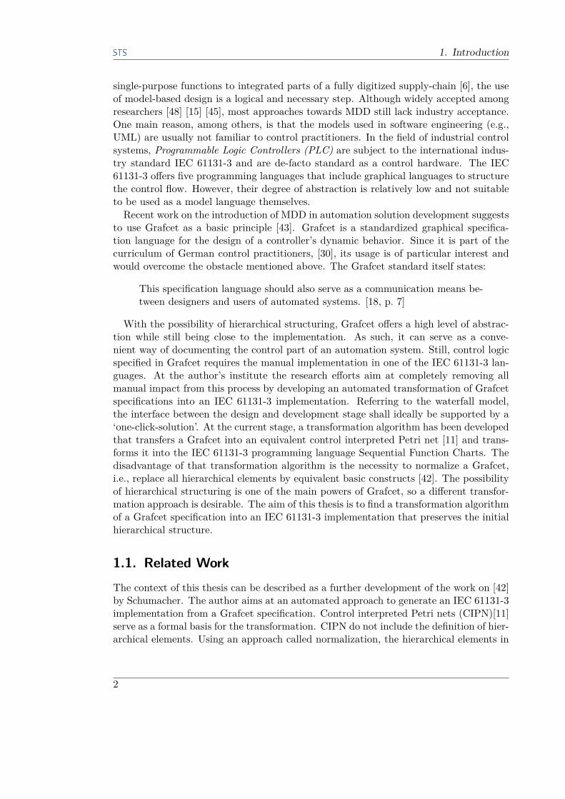
2. Background
to enable their unambiguous identification. In the example in figure 2.1, the numbers inthe step symbols are the step names, while the values inside brackets next to the transi-tions are the transition names. If more than one step precedes or succeeds a transition,a horizontal double line called synchronization is used. A step can be either active orinactive, which is indicated by the boolean step activity variable that returns true if thestep is active and false otherwise. An active step is marked with a token in the Grafcetchart. The set of all active steps at any given time instant is called the situation of theGrafcet. Referring to the example again, the situation at the current time m is sit(m)= [21,24]. The situation on initialization of the Grafcet is given by the set of initialsteps, denoted by steps with a double frame. In the example, this means sit(init) =[21,22]. Further Grafcet syntax elements are explained in the following sections.
Figure 2.1.: Structure of a Basic Grafcet
Interpretation
The interpretation of a Grafcet requires elements that relate the system’s inputs andoutputs to the internal state evolution. These elements are transition conditions andactions. Each transition has an associated transition condition, written next to thetransition symbol, which is a logical expression consisting of input and internal variables.A transition condition evaluates to true or false, depending on the logical combinationof its variables. A transition condition can also contain events, denoted by an up-arrowfor the rising and a down-arrow for the falling edge of a signal. For example, thetransition condition t1 = ↑a evaluates to true if the signal a changes its value fromfalse to true. t1 is set back to false immediately after occurrence of the event. Thetransition conditions determine the evolution of the system as described in the nextsection.Actions define the manipulation of output and internal variables by the Grafcet de-
pending on the current situation. An action is represented by a rectangle that is con-nected to a step by a horizontal line. This indicates the logical connection between the
6

2.1. Grafcet
execution of the action and the activity of the corresponding step, e.g., execution onlywhile the step is active. There are two kinds of actions: A continuous action indicatesthat an output signal has a true value when the corresponding step is active. Globally,the value of an output signal is determined by an OR operation on all correspondingcontinuous actions. This means that these signals are false if no assigned action is ac-tive. Stored actions set an internal or output variable to a dedicated value on activation/ deactivation of the corresponding step. The variable maintains this value until anotherstored action resets it. A stored action is marked by an arrow at the left edge of theaction symbol. The Grafcet in figure 2.2 contains both continuous and stored actions.On activation of step 4, the value of k is set to 5. It will keep this value until the nextactivation of step 5, when k is set back to 1. The variable signal1 is only true whilestep 5 is active and false otherwise. The same applies to signal2 and step 6.
Dynamic Behavior
The dynamic behavior of a Grafcet, i.e., the evolution from one active situation to thenext, is given by five evolution rules [18, p. 14].
Rule 1 The initial situation, chosen by the designer, is the situation at the initial time.
Rule 2 A transition is said to be enabled when all immediately preceding steps linked tothis transition are active. The clearing of a transition occurs when the transitionis enabled and when its associated transition-condition is true.
Rule 3 The clearing of a transition simultaneously provokes the activation of all theimmediate succeeding steps and the deactivation of all the immediate precedingsteps.
Rule 4 All transitions which can be cleared simultaneously are simultaneously cleared.
Rule 5 If during the operation an active step is simultaneously activated and deacti-vated, it remains active.
In this work, clearing and firing of a transition are synonymous.Particular attention has to be put on the combination of rule 3 and 4. If several subse-
quent transitions are all enabled on occurrence of an event, they all clear simultaneously.The next situation is called stable situation and is given by the set of steps that hasbeen activated by the last transition. All intermediate steps are part of an unstable sit-uation, which has only virtually been activated and deactivated. This behavior is calledtransient evolution. During transient evolution, continuous actions that belong to stepsof an unstable situation are not executed. In contrast, all stored actions are executed,no matter if their steps belong to a stable or unstable situation.
Example 2.1.1. Consider figure 2.2. Assume that in the current situation sit(m) =[3], the boolean variables e and f are true, while the boolean variables d and g arefalse. This means that only transitions t12 and t13 are enabled. The stored actionassociated to step 3 assigns the value 1 to k. If the variable d changes its value from
7

2. Background
Figure 2.2.: Example of Transient State Evolution
false to true, the next situation at timestep m+1 is sit(m+1) = [6], and the steps 4and 5 were ‘skipped’. Nevertheless, k has changed its value from 1 to 5 because of thestored action associated to step 4. At the stable situation sit(m+1), signal2 is true.The variable signal1, however, has never been true because the continuous action waspart of the unstable situation.
The evolution rules guarantee deterministic behavior[10] and allow for a simulationof the control program as a token play. Yet, if the Grafcet shall be interpreted on asequential process such as a CPU in a PLC, additional information on the orders ofrule 2, 3, and 4 is needed. A possible implementation of such an order is the basis ofsection 4.1.
2.1.2. Hierarchical Concepts in Grafcet
To improve readability of the dynamic behavior of complex automated systems and allowthe modeling of concurrent entities, the IEC 60848 offers three different ways of struc-turing a Grafcet and introducing hierarchy levels to the specification. Grafcet allowsthe composition of several Grafcets, so-called partial-Grafcets into one global Grafcet.In the application domain, these partial-Grafcets could represent the different operat-ing modes of the automated system, while the global Grafcet represents the high-levelcontrol-flow. The control-flow between the several Grafcets is realized by the differentmeans of hierarchical structuring. The IEC 60848 has evolved over time and did notcontain the possibility for hierarchical structuring in its early versions. The followingdescriptions of Grafcet-elements follow the latest version of the IEC 60848 [18].
8

2.1. Grafcet
Macrosteps
A macrostep serves as a placeholder of a part of the specification and allows the compo-sition and decomposition of a Grafcet. It is represented graphically by the step symbolwith two additional horizontal lines at the top and bottom and the prefix M in its name.Because of its placeholder function, no action should be associated to a macrostep. Thedetailed part of the specification that is replaced by the macrostep is called expan-sion of the macrostep and is specified in a separate partial-Grafcet. An expansion of amacrostep has to consist of one entry step with prefix E and one exit step with prefixS (abbreviation for French: Entrée/Sortie). A macrostep expansion can only belong toone macrostep, though this macrostep can be used several times in the Grafcet. If morethan one instance of a macrostep can be simultaneously active, the implementation re-quires several copies of the expansion respectively. The entry step becomes active oncethe macrostep becomes active, too. The expansion is then executed and the macrostepremains active until the exit step of the expansion is reached. The succeeding transitionof the macrostep can not be enabled until the exit step of the expansion becomes active.It is possible to use a macrostep without a corresponding expansion. In that case, themacrostep behaves like a normal step.
Figure 2.3.: Grafcet with Macrostep
Example 2.1.2. Figure 2.3 shows an example of the usage of macrosteps in a Grafcet.The Grafcet on the left represents the high level of an automated process that makesuse of the macrostep M2. The right partial-Grafcet is the expansion of the macrostepM2. The suffix of the entry step E and the exit step S and the label on the frame of thepartial-Grafcet are distinct references to the macrostep M2. In the current situation ofthe example, a value change of the variable a from false to true leads to the firing oftransition t1, which deactivates step 1 and activates M2 and thus E2. The macrostepexpansion is now active. The transition t2 cannot be enabled until step S2 becomesactive, e.g., by successive clearing of transition t20 and t22. When S2 is active and b istrue, transition t2 can clear and deactivate S2 and thus M2.
Macrosteps offer a way to ease modeling and improve the understanding of a Grafcet.
9

2. Background
High-level systems can be specified by using empty macrosteps in the beginning. Inlater stages of the engineering process, functionality can be added by specifying thecorresponding macrostep expansions.
Enclosing Steps
Enclosing steps offer a way of implementing a hierarchical structure between autonomouspartial-Grafcets. The activation of an enclosing step of a higher-level partial-Grafcetsimultaneously activates specific steps of a lower-level partial-Grafcet, referred to aspartial-Grafcet of enclosing steps or enclosed partial-Grafcet. The partial-Grafcet ofenclosing steps follows the five evolution rules until the enclosing step gets deactivatedagain. The enclosing step is represented by a step-symbol with a diagonal line in eachof its corners. The steps of the enclosed partial-Grafcet that are activated with theenclosing step are marked with an asterisk next to the step-symbol. A partial-Grafcetof enclosing steps contains a distinct reference to its enclosing step. The deactivation ofan enclosing step leads to the deactivation of all steps of the partial-Grafcet of enclosingsteps. The relation of an enclosing step to partial-Grafcets of enclosing steps is 1:n.
Figure 2.4.: Grafcet with Enclosing Step / Enclosed Grafcets
Example 2.1.3. In figure 2.4, the left partial-Grafcet GMain represents the highesthierarchy level. The activation of step 2 leads to the activation of the steps 22 and 32of the two enclosed Grafcets GWeighing and GMixing. The labels on their frames showthe names and the reference to the enclosing step 2. All three partial-Grafcets operateunder the evolution rules until the clearing of transition t2. This deactivates step 2 andthus all steps of GWeighing and GMixing.
Forcing Orders
Forcing orders are another way of controlling lower-level partial-Grafcets from high-levelcharts. They offer the possibility of forcing a partial-Grafcet to a specific situation. Forc-
10

2.1. Grafcet
ing orders are embedded in a double rectangle and associated to steps with a horizontalline. Table 2.1 shows the syntax of forcing orders. The forcing order is termed internal
G38,9,11 Forcing the partial-Grafcet G3 into the situationwhere only the steps 8,9,11 are active
G4INIT Forcing of G4 into the initial situationG5* Forcing the current situation of G5
G6 Forcing G6 to the empty situation (no step is active)
Table 2.1.: Syntax for Forcing Orders in Grafcet
order and has priority over the evolution rules. That means that a forced Grafcet can-not evolve until the forcing order has finished, i.e., the associated steps get deactivated.The forced Grafcet is said to be frozen. If the forcing order is not active, the Grafcetcontinues to operate under the evolution rules. The relation of forcing orders to forcedGrafcets is m:1, which means that a forced Grafcet can be forced from several differentforcing orders, as long as these orders are not active at the same time. A step can havemore than one forcing order. A forcing order has the same dynamic properties as acontinuous action, thus it is not executed when its step is part of an unstable situation.
Figure 2.5.: Grafcet with Forcing Order / Forced Grafcet
Example 2.1.4. Figure 2.5 illustrates the case where a partial-Grafcet is forced to aspecific situation. Both Grafcets are in their initial situation and apply the evolutionrules in parallel, e.g., the clearing of transition t20 deactivates step 20 and activates thesteps 21 and 22 of G1. Clearing transition t1 activates step 2, which enables the forcing
11

2. Background
Property Macrostep Enclosure Forcing OrderBehavior of subchart onactivation of hierarchicalelement
Activates entrystep E*
Activates en-closed steps
Activates forcedsituation
Behavior of subchart ondeactivation of hierarchicalelement
Deactivates allsteps
Deactivates allsteps
Continues evolu-tion under evo-lution rules
Behavior of main chartwhile hierarchical elementis active
Macrostep staysactive until exitstep of expan-sion is reached
Continues evolu-tion under evo-lution rules
Continues evolu-tion under evo-lution rules
Table 2.2.: Dynamic Properties of Hierarchical Elements in Grafcet
order associated to the step. At the same time, the Grafcet G1 is forced to the situationwhere only the steps 21 and 24 are active. This forcing just activates and deactivatesthe necessary steps, ignoring the current situation of the forced Grafcet. As long as step2 remains active, G1 remains frozen. Once step 2 gets deactivated, G1 continues normalevolution, starting from the forced situation.
Summary of Dynamic Behavior for Hierarchical Elements
The basis for the transformation rules for translating Grafcet elements into IEC-61131-3-structures is the dynamic behavior. Ensuring a correct transformation means ensuringequivalent dynamic behavior. Each of the structure presented in this chapter has adifferent impact on the evolution of the high- and low-level partial-Grafcets. The com-parison of these properties in table 2.2 allows distinguishing the hierarchical structuresof Grafcet.
2.1.3. Formal Definitions of Grafcet
To be able to transform Grafcet into an IEC 61131-3 implementation, or in fact into anyother representation, it is necessary to have a formal background of the Grafcet syntax.On that basis, a transformation algorithm is able to identify the Grafcet elements andtransform them. We developed the following definitions, based on [38] and extendedby the notions of enclosures and forcing orders. We shall use these definitions for thedevelopment of a Grafcet interpretation algorithm for sequential systems in section 4.1,as well as for the construction of a prototypical transformation program in section 5.2.
Definition 2.1.1. A Grafcet G is a 4-tuple (IG, OG, CG, SInitG) where• IG is the non-empty set of logic inputs• OG is the non-empty set of logic outputs• CG is the set of Grafcet charts
12

2.1. Grafcet
• SInitG is the set of initial steps
As table 2.2 illustrates, macrostep expansions and enclosed partial-Grafcets are differentfrom other charts in the way that they contain a set of ‘special steps’. Thus, the chartsset is divided into the set CC of classical charts, the set CM of macrostep expansioncharts, and the set CE of enclosed partial-Grafcets.
Definition 2.1.2. A classical chart c ∈ CC is defined by a 4-tuple (m,S, T,A) where• m is the name of the chart• S is the non-empty set of steps s of c• T is the set of transitions t of c• A is the set of actions a of c
Definition 2.1.3. A macrostep expansion chart cm ∈ CM is defined by a 6-tuple(m, sI , sO, Soth, T, A) where• m is the macro-step name• sI is the input step of the expansion• sO is the output step of the expansion• Soth is the set of other steps s of cm• T is the set of transitions t of cm• A is the set of actions a of cm
Definition 2.1.4. An enclosed partial-Grafcet (or partial-Grafcet of enclosed steps)enc ∈ CE is defined by a 5-tuple (xm,Senc, Soth, T, A) where• xm is the name of the enclosure• Senc is the non-empty set of enclosed steps sx in enc• Soth is the set of other steps s in enc• T is the set of transitions t of enc• A is the set of actions a of enc
Definition 2.1.5. The step sets are divided into the sets of normal steps Ss, the sets ofmacrosteps Sm and the sets of enclosures Se. All steps s ∈ (Ss ∪ Sm ∪ Se) are 3-tuples(m,x, t) where• m is the name of s• x is a boolean variable indicating if s is active or not• t is a timer variable indicating the active duration of s
Let S(cm) be the set of all steps of the macrostep expansion chart cm (S(cm) = sI , sO∪Soth), S(enc) be the set of all steps of the enclosed partial-Grafcet enc (S(enc) = Senc ∪Soth) and SG be the set of all steps s of the Grafcet.
Definition 2.1.6. A transition t ∈ T of a chart c is defined by a 3-tuple (SB, SA,ECond(IG,SG)) where• SB is the set of immediate predecessor steps of t (before)• SA is the set of immediate successor steps of t (after)• ECond(IG,SG) is a transition condition. It is a boolean expression of inputs and step
activity variables
13

2. Background
Let TG be the set of all transitions t of a Grafcet.
The set of actions A is divided into the set AS of stored actions with a set of associatedoutputs OS , the set AC of continuous actions with outputs OC and the set AF of forcingorders. The union of OS and OG forms the output set OG of a Grafcet OG = OS ∪OC .Let AG be the set of all actions a of a Grafcet. Let AGS , AGC and AGF be the sets ofall stored actions aS , all continuous actions aC and all forcing orders aF of a Grafcetaccordingly.
Definition 2.1.7. A continuous action aC ∈ AC of a chart c is defined by a 3-tuple(s, o, ECond(IG,SG)) where• s is the step to which the action is connected• o is the output which is manipulated by the action• ECond(IG,SG) is a continuous action condition, consisting of a boolean expressionon inputs and step activity variables
Definition 2.1.8. A stored action aS ∈ AS of a chart c is defined by a 4-tuple(s, o, val, inst) where• s is the step to which the action is connected• o is the output which is allocated by the action• val is the value that is assigned to the output• inst is the instant when the allocation is done:inst ∈ StepActivation, StepDeactivation
Definition 2.1.9. A forcing order aF ∈ AF of a chart c is a 4-tuple (s, c, op, sit) where• s is the step to which the action is connected• c is the forced partial-Grafcet from the set of classical charts, c ∈ CC
• op is the kind of forcing operation: op ∈ Spec, Init, Current, Empty, whereSpec is a specific situation of the forced partial-Grafcet, Init the initial situation,Current the current situation and Empty the empty situation where no step isactive• sit is the set of steps s ∈ S of the forced partial-Grafcet that marks the forcedsituation
2.2. IEC 61131-3
The IEC 61131-3 is a part of the IEC 61131 international standard. The IEC 61131consists of 8 different parts that deal with different aspects and requirements of PLCsystems. The third part, i.e., the IEC 61131-3, serves as a standard for PLC program-ming. The most current edition is the third revision of the norm and has been releasedin 2013 [20]. Compared to its predecessor, it includes a major new aspect regarding theobject-oriented programming of PLC systems. Since the norm has been developed bythe International Electrotechnical Commission with the contribution of major PLC ven-dors and automation research institutions, it is widely accepted and de-facto standard
14
2.2. IEC 61131-3
within the automation industry[49]. Its compliance is controlled by a consortium withstrong industry background, the PLCopen committee (see section 5.1.2 on page 46).The IEC 61131-3 describes five different languages that can be used to program a PLC.
These include two textual languages (Instruction List (IL) and Structured Text (ST)),as well as three graphical languages (Function Block Diagram (FBD), Ladder Diagram(LD), and Sequential Function Charts (SFC)). The general means of structuring a PLCprogram as well as the language-independent elements like variables are also part of thestandard.
2.2.1. General PLC Functionality and Program Structuring
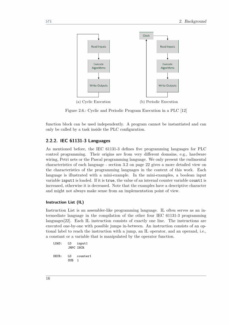
The core of a PLC is a signal processing unit, where the execution of a control programconnects input signals and internal variables to output signals or other internal variables.The processing part of a PLC typically works in a cyclic or periodic way, as illustratedin figure 2.6. After reading the inputs, the control program is executed and the outputsare written after its termination. This principle originates from the initial hard-wiringof control logic in early automation control systems.According to the IEC 61131-3 standard, a PLC system itself is called a configuration. It
may consist of one or more CPUs, which are referred to as resources. A resource consistsof a set of global variables and of task declarations that assign run-time properties to theactual control program elements described below. These run-time properties include thecycle time in which the associated program elements are called and a priority flag thatcompares the priority of the associated element to other elements running concurrently.The function of the latter is implementation-dependent. Systems may either implementpreemptive scheduling, i.e., a task with lower priority is interrupted immediately, ornon-preemptive scheduling, i.e., the resource waits for termination of the task with lowerpriority until tasks with higher priority may start [22]. This behavior is an importantconsideration in section 3.1.A PLC control program consists of a collection of functionally independent software
units, called program organization unit (POU). The norm defines three different typesof POUs, which have different characteristics: functions, function blocks, and programs.A function can have an arbitrary number of input values and exactly one output value.
The property of a function is that it always gives the same result for the same inputvalues, regardless of the system’s state. As such, it does not have any internal memory,is not allowed to read any global variables and can only call other POUs of type function.An example of a function is the provision of a standard mathematical operation, e.g.,root(x, y).Programs and function blocks used to have only minor differences until the introduc-
tion of object-oriented extensions for function blocks in the latest edition of the IEC61131-3. Both POUs can have an arbitrary number of input and output values and cansave local data over several invocations, i.e., have internal memory. The main differencebetween programs and function blocks is that function blocks have to be instantiatedto be called by other function blocks and programs. Each instance represents its owncopy of the POU in the PLC memory, which means that several instances of the same
15
2. Background
(a) Cyclic Execution (b) Periodic Execution
Figure 2.6.: Cyclic and Periodic Program Execution in a PLC [12]
function block can be used independently. A program cannot be instantiated and canonly be called by a task inside the PLC configuration.
2.2.2. IEC 61131-3 Languages
As mentioned before, the IEC 61131-3 defines five programming languages for PLCcontrol programming. Their origins are from very different domains, e.g., hardwarewiring, Petri nets or the Pascal programming language. We only present the rudimentalcharacteristics of each language - section 3.2 on page 22 gives a more detailed view onthe characteristics of the programming languages in the context of this work. Eachlanguage is illustrated with a mini-example. In the mini-examples, a boolean inputvariable input1 is loaded. If it is true, the value of an internal counter variable count1 isincreased, otherwise it is decreased. Note that the examples have a descriptive characterand might not always make sense from an implementation point of view.
Instruction List (IL)
Instruction List is an assembler-like programming language. IL often serves as an in-termediate language in the compilation of the other four IEC 61131-3 programminglanguages[22]. Each IL instruction consists of exactly one line. The instructions areexecuted one-by-one with possible jumps in-between. An instruction consists of an op-tional label to reach the instruction with a jump, an IL operator, and an operand, i.e.,a constant or a variable that is manipulated by the operator function.
LOAD: LD input1JMPC INCR
DECR: LD counter1SUB 1
16

2.2. IEC 61131-3
ST counter1JMP END
INCR: LD counter1ADD 1ST counter1
END: RET
Listing 2.1: Instruction List Mini-Example
Structured Text (ST)
Structured Text is a Pascal-like high-level programming language. As such, it includesloops, mathematical functions, iteration, and conditional execution. Its higher abstrac-tion level compared to IL offers better readability and more intuitive programming totoday’s users that are usually familiar with at least one C-like language. The downsideof compiled ST code is that it is usually slower than a direct implementation in IL.However, this issue can be neglected on modern PLC systems because of fast executiontimes.
IF input1 THENcounter1 := counter1 + 1;
ELSEcounter1 := counter1 - 1;
END_IF;
Listing 2.2: Structured Text Mini-Example
Ladder Diagram (LD)
Ladder Diagram is a graphical language based on electromechanical relay systems. Twovertical lines representing power rails are connected by rungs which embed graphicalsymbols that correspond to contacts, coils and function blocks. The left power rail hasthe logic state 1, leading to a logical flow from left to right. The resulting LD networkis executed from top to bottom.
Figure 2.7.: Ladder Diagram Mini-Example
17

2. Background
Function Block Diagram (FBD)
Function Block Diagram is a graphical language that reflects the basic idea of function-oriented sequence chains. FBD is a network graphic, where rectangular boxes thatrepresent an operation on their input variables are connected by horizontal and verticallines that represent data flow and can pass any IEC 61131-3 variable type. A FBD di-agram is usually evaluated top-to-bottom, although vendor-dependent implementations(e.g., via the assignment of sequence numbers) are possible. It is possible to directlytransform a LD control program into a FBD representation because both languagesshare the element wiring concept.
Figure 2.8.: Function Block Diagram Mini-Example
Sequential Function Charts (SFC)
Sequential Function Charts are mainly used to describe the control flow of a program.SFC is a classical Petri-net like step / transition system that is said to be based onGrafcet [22]. The entire program is broken down into smaller units and the control flowbetween them is controlled via conditional transition firings. The use of SFC facilitatesthe design of parallel processes. The small units themselves are usually programmedwith the other four languages or using SFC again.
Figure 2.9.: Sequential Function Charts Mini-Example
18

2.2. IEC 61131-3
2.2.3. Object-Oriented Extensions
A major change in the current and third revision of the IEC 61131-3 is the introductionof object-oriented programming extensions. While in desktop application developmentthe use of object-oriented programming (OOP) with languages like C++ and Java iscommon, the approach is relatively new to the world of PLC programming. Neverthe-less, the introduction of OOP to the IEC 61131-3 received great endorsement, offeringimproved reusability [49], the usage of software product lines for control programs [32],and an extensive usage of UML class diagrams [31] in IEC 61131-3 development [50].The new language elements include:
• A fourth POU of type class, which follows the class concept of the known OOPlanguages. A class includes methods and an internal and external data structure.A class can implement an interface with method prototypes. Subclasses can inheritfrom a parent class and extend or overwrite its methods and data structure. Touse a class inside a program, it has to be instantiated (i.e., an object has to becreated).
• An interface that serves as an abstraction for a class or a function block.
• Object-oriented extensions of function blocks, i.e., the inclusion of methods andthe possibility to implement interfaces and inherit and extend from other functionblocks.
Figure 2.10 shows how these new language elements interact. Early drafts of the new
Figure 2.10.: Overview of Inheritance and Interface Implementation [20, p. 119]
revision focused primarily on object-oriented extensions for function blocks. The conceptof function block instantiation already follows the principle of a class definition andobject instantiation in OOP [49]. A first PLC development tool that included suchobject-oriented extensions was Codesys V3 (see section 5.1.1 on page 45), which alsoserved as a reference implementation during the standardization process of the new IEC61131-3 revision [50]. Until today, there is yet no other tool that implements any of thenew OOP language elements. Furthermore, Codesys has not been expanded to the new
19

2. Background
POU type class. In our work, we will thus focus on the object-oriented extensions forfunction blocks, even if a class-implementation seems equivalent or even superior.Before the introduction of these extensions, a function block was limited to only one
procedural operation. If a function block had to perform different tasks, e.g., initializa-tion and different modes of operation, it had to be called with a specific set of input valuesthat could be used inside the function block for a case-selection. With the introductionof methods, these different tasks can be separated. Apart from the obvious advantage ofbetter structuring, it also significantly improves readability because a task can (ideally)be clearly identified by the name of its method. This is particularly interesting for ourtransformation concept, which we will point out in section 3.2.2.For a discussion of the benefits and use-cases for the other new OOP language elements
of the IEC 61131-3, refer to the sources cited in this section. We will point out somepotentials for our concept in the outlook section 6.1.
20

3. Concept Development for theTransformation
The general aim of this thesis is to transform a Grafcet specification into an IEC 61131-3implementation. The latter term ‘IEC 61131-3 implementation’ is very vague and needsto be specified before a transformation concept can be developed. First thoughts need toconsider a target architecture. The concept of configurations, tasks and POUs offers agreat number of possible ways to structure a control program hierarchically. Section 3.1discusses possible implementations. Furthermore, it is neither possible nor intended tosimply translate one IEC 61131-3 language into another [35]. Thus, a transformationconcept needs to focus on one specific target language. A discussion of possible targetlanguages and a final decision is given in section 3.2.
3.1. General Program StructureThe final transformation concept is based on some general considerations regarding thestructure of the control program on the PLC.One decision that has to be made is the choice of the target configuration. For the
sake of simplicity, we decided to use a simple configuration with only one resource. Sucha program will also run on more advanced systems, which is not the case in the contraryway. Keeping the property of forced Grafcets that ‘run in parallel to the main Grafcet’ inmind, a first idea was to exploit the possibility of assigning program elements to differenttasks that run concurrently with different priorities. The program elements in the taskscould exchange information and start / stop each other via global variables becausethese are declared on resource level. However, the system-dependent difference betweenpreemptive and non-preemptive scheduling does not allow for a universal transformationapproach. Such a concept would always be limited to a certain type of PLC.The above considerations lead to a target architecture of one configuration with one
resource that includes only one task that controls only one main program.For the overall aim to keep the hierarchical structure with partial-Grafcets, we have
to encapsulate the transformed IEC 61131-3 implementation of each partial-Grafcet intoits own POU. The decision for a POU type can be done by exclusion:• A POU of type function is not applicable because it cannot save state information,
which is the most essential part of Grafcet.
• A program can only be called by its task, but not by any other POU. Becausepartial-Grafcets exchange information via the implicit links of hierarchical ele-ments, the resulting POUs need to be able to call each other. A workaround withthe usage of different tasks and global communication variables has been consideredimpractical above, so programs are not applicable either.
• The remaining POUs of type function block and class both suit the needs of thetransformation very well. They can save state information and are able to call each
21

3. Concept Development for the Transformation
other. With the provision of dedicated methods, these POUs are able to commu-nicate with each other in a convenient way. The usage of global communicationvariables is not necessary.
Section 2.2.3 on page 19 points out that, although part of the norm, the POU class hasnot yet been implemented in any software development environment. We thus opted forfunction blocks as the IEC 61131-3 counterpart for a partial-Grafcet.
3.2. Choice of IEC 61131-3 Programming Language
For the successful transformation of a hierarchical Grafcet into an IEC 61131-3 imple-mentation, the choice of the appropriate IEC 61131-3 programming language is crucial.We define the following quality measures that have to be met to ensure practicabilityand acceptance of the transformation concept:
Similarity The most obvious point of the transformation is that the transformed codeshall show the same dynamic behavior on a PLC as one would expect from theGrafcet. This point could also be called ‘equivalence’, but due to the differences inthe event-based Grafcet and the cyclic-sequential PLC, similarity is a more preciseexpression.
Portability Although the IEC 61131-3 defines a global standard for the programmingof PLC-systems, it still leaves room for interpretation and thus leads to vendor-dependent implementations. The transformation algorithm shall avoid such am-biguous structures to ensure that the produced code can run on any IEC 61131-3software development environment.
Readability As mentioned in section 1, the specification of the control algorithm on theone hand and the implementation and maintenance of the control program on theother hand are typically done by different users with a different background. It iscommon practice that minor changes are done directly in the code. The producedcode has to be easily readable without knowledge of the transformation algorithm.Ideally, the control flow of the automated system can be directly seen from thecontrol program.
Maintainability Small changes to the control flow (e.g., different actor trigger, additionalchecks etc.) shall also result in only small changes in the code. Implicit relationsbetween signals and variables should be avoided.
A transformation approach that helps to ensure some of these quality metrics hasbeen established by Frey [14] and picked up by Schumacher [42]: One-to-one correspon-dence is an approach which implies that a Grafcet-element shall have a direct corre-spondence in its IEC 61131-3 implementation. The one-to-one correspondence allows aneasy reinterpretation of the produced code, avoids implicit relations between variablesand ensures that the user knows where to find parts of the code he needs to be changed.
22

3.2. Choice of IEC 61131-3 Programming Language
Furthermore, this approach is a good foundation for future improvements in the do-main of model-based-development with Grafcet, e.g., bi-directional transformation (seesection 6.1).Section 2.2.2 gives a brief overview of the available IEC 61131-3 languages. This work
only considers Sequential Function Charts and Structured Text as target languages forthe transformation. The remaining languages were omitted due to the following reasons:
Instruction List The transformation of Signal Interpreted Petri Nets (SIPN) to an IEC61131-3 implementation in [14] uses IL as a target language without further rea-soning for this choice. However, the most recent version of the IEC 61131-3 normstates that as an assembler-like language, IL is outdated. It will not be includedin the next version of the norm [20]. The transformation should not be based ona language that is considered ‘deprecated’ [20, p. 195].
Ladder Diagram Due to the fact that LD is based on the wiring of relais inside a con-troller, it is ‘far away’ from an abstract control-flow language like Grafcet. A LDimplementation would most likely not fulfill the readability quality metric.
Function Block Diagram To effectively model a control-flow given in Grafcet, a FBDimplementation would have to model states and transitions as function blocks andconnect them. Such an implementation would look similar to an SFC implemen-tation, so SFC could be used straightaway.
3.2.1. Analysis of Sequential Function Charts as a Target Language
Before the analysis of the potentials of SFC as a target language, this section gives abrief description of the functionality of SFC. For a detailed introduction, refer to [22] ordirectly to the IEC 61131-3 [20].The structure of a SFC is based on steps and transitions, two disjoint sets of knots that
are connected by directed arcs. A step consists of two properties that indicate its activity(∗.X) and the time that has passed since the last activation of the step (∗.T ). Each stepcan be associated to a set of actions. Actions can either set a boolean variable or executea procedure that can be written in any of the IEC 61131-3 languages. The dynamicexecution of an action depends on its qualifier. For this work, the most importantqualifiers are the S-qualifier for a stored execution of an action and the N-qualifier thatactivates the corresponding action for the active duration of the corresponding step.Each transition has an associated boolean transition condition. The dynamic behaviorof an SFC underlies a set of evolution rules, similar to those of Grafcet and Petri nets.The initial state is marked by an initial step. The succeeding states are reached bysequential firing of transitions. A transition fires if all its preceding steps are active andits transition condition evaluates to true. Actions are executed when their correspondingstep is active. Due to the cyclic nature of PLCs, these SFC execution characteristicsfollow a certain execution order that is repeated in each scan cycle. This major differenceto the event-based Grafcet evaluation is picked up later in this section.
23

3. Concept Development for the Transformation
Most work related to the transformation of specification languages to an IEC 61131-3 implementation focuses on SFC as a target implementation language. Katzke et al.examine the transformation of UML and suggest SFC because of its capability to directlymodel discrete and batch processes [24]. Klein et al. analyze the transformation of aSIPN model into an SFC implementation program [26]. The authors use model checkingtechniques to validate the SIPN model, transform it into SFC and validate it again.They justify the choice of SFC with the syntactic similarity to SIPN, but also mentionmajor differences that have to be considered in the context of this work as well:
• SFC does not have transient states. A state is always active for at least one PLCcycle.
• There can be only one initial step in an SFC.
These restrictions apply to Grafcet as well, because transient states and multiple initialsteps are also included in Grafcet. In the validation process of the SFC using the modelchecker SMV, a property that has been validated on the SIPN does not hold on thegenerated SFC. This is due to the lack of transient state behaviour. A transformationapproach that gives respect to this property would be desirable.According to [5] and [22], the SFC language is based on the Grafcet norm IEC 60848
[18]. Because of their syntactical similarity, the two are often mixed up, especially inthe anglophone application domain (e.g., [46], [13]). However, Grafcet and SFC aredifferent in their dynamic behaviour, mostly because of the sequential character of SFC.The Grafcet norm itself explicitly mentions the important semantic differences in theappendix:
IEC 60848 and IEC 61131-3 each have a specific domain of application:a behaviour specification language (GRAFCET – GRAphe Fonctionnel deCommande Etape Transition) independent of any specific technology of im-plementation, for IEC 60848, and a specific programming language (SFC– Sequential Function Chart), for IEC 61131-3. GRAFCET of IEC 60848is used by a grafcet chart to describe/specify the behaviour of system, asviewed from "outside" of the system, while the SFC language of IEC 61131-3is used to describe (part of) the implemented software structure "inside" ofthe system. [18, p. 52]
and further
If the two languages were both used to describe a control system, the twodescriptions (two different document kinds) would in a given case look graph-ically similar. However, they would not have the same meaning, not even ifthey were graphically identical. This would just indicate that the structureof the software program, described in a software diagram, behaves in a waysuch that it can be described with a graphically similar grafcet chart. Theproperties of the underlying elements associated with the graphical elementrepresentations are nevertheless different in the two cases. [18, p. 52]
24

3.2. Choice of IEC 61131-3 Programming Language
Apart from the known semantic differences between Grafcet and SFC, the lack of hier-archical elements in SFC is another issue when choosing the appropriate target language.There is yet no known effort to transform Grafcet including its hierarchical elements toSFC. David and Alla suggest to transform CIPN into SFC, but limit the scope of theinterpretation algorithm to basic Grafcets without abbreviations (i.e., hierarchical ele-ments) [11]. Schumacher includes hierarchical elements in the Grafcet specification, butmerges all partial-Grafcets into one remaining Grafcet (i.e., normalization of all Grafcets)before the transformation [42]. The reason why hierarchical elements are not included isthat the syntactical similarity between Grafcet and SFC is limited to elements of a basicGrafcet. There is no element in SFC that resembles the hierarchical elements macrostep,enclosure and forcing order. That means that their behavior has to be modeled withbasic elements. The impact of all hierarchical elements on the dynamic behavior of aGrafcet can be traced back to the introduction of implicit links and conditions. Whentrying to model the hierarchical elements of Grafcet in SFC, these implicit links need tobe uncovered and explicitly modeled.We shall demonstrate on a number of examples that the implementation of such ad-
ditional links can be awkward to handle and to some extent defeats the quality measurereadability.
(a) Forcing in Grafcet (b) Similar Behavior in SFC
Figure 3.1.: Simple Example for the Transformation of Forcing
Forcing Orders in SFC
In the case of a forcing order, explicit models for the implicit links are:
1. Additional transitions from every step to the forced steps with transition conditionforcing step == 1 to bring the partial-Grafcet to the forced situation.
2. Additional condition NOT forcing step == 1 for each existing transition so thatthe Grafcet does not evolve while the forcing order is active.
25

3. Concept Development for the Transformation
3. In the case of a parallel branch: A synchronization and transition from everypossible combination of steps that can be active at the same time to the forcedsteps. This is due to the fact that a step cannot be activated twice, so two activesteps that link to the same step need to be synchronized.
Example 3.2.1. Consider the Grafcet in figure 3.1a on the previous page. From anycurrent situation sit(t), the forced Grafcet G1 evolves to the situation sit(t+1) =S5 on activation of step S2 in GMain. An SFC that shall show similar behavior needsto have corresponding additional transitions and links. The partial-Grafcet G1 will stayin the situation sit(t+x) = S5 during the time x that S2 is active. Even whentransition t13 is fireable, the active forcing order suppresses its firing. All transitionsin the corresponding SFC need to be extended so that they will not fire while theforcing order is active. Figure 3.1b shows such a SFC implementation that preserves thehierarchical structuring of the corresponding Grafcet and implements the implicit links.
Figure 3.2.: Extended Example for the Transformation of Forcing - Grafcet
Example 3.2.1 is still easy to read because there are only a few additional links thatare easy to handle. However, if the Grafcet contains parallel branches, the number ofimplicit transitions increases greatly because of the necessity of combining all steps ofparallel branches:
Example 3.2.2. The partial-Grafcet G1 in figure 3.2 will evolve from any situationsit(t) to the situation sit(t+1) = S20 on activation of step S2 in GMain. Consid-ering the shown current situation sit(t) = 21, 24, this means that in an SFC thesetwo steps have to be synchronized and linked to step S20. The necessary transition hasthe condition GMAIN.S2.X to indicate that the forcing order is active. Such an additionalsynchronization needs to be implemented for all possible situations where two steps canbe active at once, i.e., sit(t) = 21, 22, sit(t) = 21, 24, sit(t) = 23, 22
26

3.2. Choice of IEC 61131-3 Programming Language
Figure 3.3.: Extended Example for the Transformation of Forcing - SFC
and sit(t) = 23, 24. The SFC in figure 3.3 contains all necessary additional ele-ments to model the Grafcet’s behavior.
Comparing the original Grafcet in figure 3.2 to the corresponding SFC in figure 3.3,it becomes apparent that already quite simple Grafcets result in relatively complicatedSFC implementations. Furthermore, while the given SFC is already difficult to read, them:1 relation of forcing orders to forced Grafcets leads to additional complexity. If G1was forced by another forcing order in GMain (i.e., a forcing order associated to step S1),a second set of additional transitions and transition conditions would have to be addedto the chart.The example of a forcing order underlines why the correct implementation of transient
state behavior is important when modeling a Grafcet with hierarchical elements. Theforcing order has the same properties as a continuous action, which means that if itlinks to a state that is only traversed during transient state evolution, the correspondingforced Grafcet is unaffected and continues normal evolution. In SFC however, eachstep is active for at least one cycle. That means that even if the forced Grafcet willnot "freeze", it will evolve to the forced situation and continue evolution from there.Before considering forcing orders, simply ignoring transient states meant that signals incontinuous actions emitted a very short pulse during one cycle, which could probablybe without effect on a real world plant. In our case, ignoring transient state evolutionwould mean severe differences in dynamic behavior.
Macrosteps in SFC
To model the implicit links of a macrostep in SFC, one needs to add:
• A link from the transition preceding the macrostep to the entry-step of the macrostep
27

3. Concept Development for the Transformation
expansion, which turns the transition into a divergent synchronization.
• A link from the exit-step of the macrostep expansion to the transition succeedingthe macrostep, which turns the transition into a divergent synchronization.
Modeling these links with the macrostep and its expansion in two different functionblocks requires a workaround. The function block has to be called as an action withqualifier N to make sure the function block is only active while the corresponding stepis active. To model the first link, the exit- and the entry-step of the expansion have tobe connected via a transition with condition "macrostep not active". The final actionevaluation will fire that transition once the macrostep is left and bring the function blockback to its desired initial state before it is deactivated. Adding an additional condition"exit step of expansion active" to the transition succeeding the macrostep models thesecond link. Figure 3.4 shows such a possible SFC implementation of the Grafcet infigure 2.3 on page 9.
Figure 3.4.: Example of the Implementation of the Grafcet in Figure 2.3 in SFC
Enclosures in SFC
The set of implicit links of an enclosure results in the following SFC elements:
• Activation / deactivation of the enclosed Grafcet together with activation / deac-tivation of the enclosure.
• Additional transitions from every step to the enclosed steps with condition "enclo-sure not active".
• Additional transition conditions "enclosure active" to ensure mutual exclusivity ofconcurrent transitions.
In analogy to the Macrostep model, the second link is needed to bring the function blockback to the situation determined by the set of enclosed steps on deactivation of the en-closure. This way, the function block is already in the right state when the corresponding
28

3.2. Choice of IEC 61131-3 Programming Language
enclosure gets activated again. The SFC in figure 3.5 is an implementation of the enclo-sure example in figure 2.4 on page 10. While this still looks easy to handle because of a
Figure 3.5.: Simple Example of the Transformation of Enclosure - SFC
relatively small number of additional elements, Grafcets with parallel branches requirethe same approach that is needed in the modeling of a forced Grafcet. All possiblecombinations of steps that can be active at the same time need to by synchronized andthen linked to the set of enclosed steps.
Further relevant characteristics of SFC
Another issue of SFC is the lack of a formal semantics, which results in vendor-dependentbehavior. This has been discussed in great detail in [5], which also gives a basis for aformal semantics. The current version of the IEC 61131-3 does not include this formalsemantics, so the vendor-dependent issues remain:
• The order in which simultaneously fireable transitions are fired is defined by apriority rule. However, the exact implementation of this rule is not defined, sosome tools might evaluate such transitions "from left to right", others might use adifferent approach.
• It is not defined if transitions are evaluated and fired before actions are executed,or if the reverse order is applied. If the value of an action or transition conditionis subject to the activity of a certain step in the chart (as in the case of modelinga forcing order), the evaluation order can influence the dynamic behavior.
• The priorities of a parent SFC and its nested SFCs (i.e., an action that is modeledin SFC) are not defined. Furthermore, it is vendor-dependent if a nested SFCremains in its current state when its deactivated, or if it starts with its initial stepon its next activation.
The second point is also the subject of [16]. Hellgren et al. analyze the SFC executionorder defined by the PLCopen committee ([35], also see section 5.1.2), two European
29

3. Concept Development for the Transformation
and one Japanese system vendors and encounter three different algorithms being used.We discuss the different characteristics of possible evaluation algorithms in section 4.1.
Summary
The aim of this thesis is to find a suitable way to transform the hierarchical elementsof Grafcet into an IEC implementation while preserving the hierarchical structure. Thissection shows that using SFC, it is in principle possible to keep the structure of acollection of partial-Grafcets and transform them separately into function blocks. Adiscussion of the quality metrics defined in the beginning of this chapter shows why wedid not choose SFC as a target language and favored an implementation in StructuredText:
Similarity The lack of transient states is a major difference to the dynamic behaviorof Grafcet. This can, for example, lead to undesired behavior of forcing orders.To overcome this, it would be necessary to limit the Grafcet design in a way thattransient evolution cannot happen (e.g., mutually exclusive succeeding transitions).
Portability The different execution orders and transition evaluation priorities of thedifferent vendors make it impossible to guarantee that the transformed code willbehave the same on any hardware. This quality metrics is violated.
Readability The SFC in figure 3.3 on page 27 is a good example of how the usageof SFC violates this quality metrics. The additional elements needed to modelimplicit links of hierarchical element lead to confusing and hard-to-read SFCs.
Maintainability Minor modifications include the variation of transitions conditions andactions. The transformation does not add redundancy or hidden links betweenactions or transitions, so if the user finds the transition or actions he wants tochange, it can easily be done. This quality metrics is met.
3.2.2. Analysis of Structured Text as Target LanguageStructured Text programs consist of a number of statements that are evaluated fromtop-to-bottom during program execution. Statements include variable assignments, dif-ferent kinds of selections (IF, CASE) and different kinds of loops (FOR, WHILE, REPEAT).Statements can also consist of function block or method calls. These are all principleswell known from languages like C and PASCAL. Again, for further reference see [22] ordirectly the IEC 61131-3 [20].Although [14] uses Instruction List for transforming signal interpreted Petri nets to
IEC 61131-3, which we did not consider for our work, the general approach is verypromising. Places, which correspond to steps in Grafcet, are modeled as boolean vari-ables that indicate whether a place is marked or unmarked. The program constantlyevaluates all transitions as to if they are enabled and fireable. If so, the boolean variablefor the preceding step is deactivated and the succeeding step activated. This textualimplementation of a sequencer is a quite basic approach in PLC programming. Using
30

3.2. Choice of IEC 61131-3 Programming Language
the same concept, an implementation of a sequencer in Ladder Diagram is possible [16].In essence, such an implementation is a textual description of the Grafcet’s dynamicbehavior and enables the explicit modeling of the systems execution, which is implicitin SFC and cannot be altered.Such an implementation in Structured Text requires the definition of a Grafcet inter-
pretation algorithm for sequential systems. The development of this algorithm is part ofthis work in section 4.1. With the object-oriented features of function blocks introducedin section 2.2.3, each function block that represents a partial-Grafcet provides a standardset of methods that correspond to the steps of such an algorithm. Dedicated methodsto alter a function block’s state from the outside simplify the modeling of implicit linksof hierarchical structures severely. Using this approach, an additional POU would beneeded that instantiates all function blocks and implements the interpretation algorithmvia calling the specific methods of each function block.The author of [14] suggests three different ways to take care of transient state evolution.
In a direct modeling approach, a boolean variable δ is defined that is set to false beforethe evaluation of transitions. If a transition fires, δ is set to true. This cycle executesuntil δ remains false during the transition evaluation, which indicates that a stable statehas been reached. Two alternative concepts deal with the fact that the ordering of thetransition code segments influences the code execution. The pseudo-code segment inlisting 3.1 illustrates this behavior.
1 //Transition 02 IF transition0 enabled AND Place0 marked THEN3 unmark Place04 mark Place15 END IF67 //Transition 18 IF transition1 enabled AND Place1 marked THEN9 unmark Place1
10 mark Place211 END IF
Listing 3.1: Pseudo-code for state evolution after [14]
Assuming that transition0 and transition1 are true and Place0 marked, we wouldsee transient behavior in the given order. After code execution, Place2 is marked andPlace1 seems to be skipped. However, when we change the evaluation order, we evaluatetransition 1 first. This evaluates to false because Place1 is not marked. Afterwards,we evaluate transition 0 which unmarks Place0 and marks Place1. In this case, aftercode execution, we see that Place1 is marked. Using a simulative respectively analyticaldetermination approach, a code segment ordering that ensures transient behavior can becomputed. In this work, we shall use the direct modeling approach to keep the programsimple.Textual source code written in Structured Text or Instruction List can be compiled
and executed on any type of PLC. The execution does not depend on any vendor-specificinterpretations.
31

3. Concept Development for the Transformation
The discussion of the quality metrics shows why we favored Structured Text as a targetlanguage for the transformation. Some of the discussed advantages are introduced insection 4.2.
Similarity The possibility of implementing transient behavior is a big step towards be-havioral similarity between Grafcet and the PLC implementation. Furthermore, wecan directly implement a Grafcet interpretation algorithm for sequential systemsand influence the evaluation order of elements.
Portability A Structured Text control program can run on any type of PLC. Thereare still some limitations regarding the portability, but these result mostly fromdifferent implementation stages of new IEC 61131-3 elements and data exchangeformats (see section 5.1.2).
Readability Naturally, a control program written in a textual language requires morework to understand the program than a simple graphical representation. However,the implicit links and additional elements needed to model hierarchical behaviorare separated from the standard set of methods. The initial Grafcet can easily bederived analyzing only a subset of the Structured Text program, which we discussin section 6.1.1 on page 59.
Maintainability To change a transition condition or an action’s output behavior, onlyone line in one method needs to be changed. This quality metrics is met.
32

4. Transformation Concept
With a concept for a program structure and the choice for a target language for thetransformation approach, the next step is to find a representation of Grafcet elements inStructured Text to be able to derive an IEC 61131-3 program with equivalent dynamicbehavior. Section 4.1 is a discussion of how to interpret the evolution rules of Grafcet ona sequential machine. The succeeding section contains the actual transformation conceptand shows how any Grafcet can be transformed into an IEC 61131-3 representation usingthis concept.
4.1. Grafcet Interpretation AlgorithmThe attempt to find a formal definition of Grafcet in [42] results in an interpretation asa control interpreted Petri net. This approach is based on [11], where a discussion of thesimilarity of Grafcet and CIPN together with the Algebra of Events results in the twofollowing statements:
• If a control interpreted PN is interpreted as a Grafcet, it has exactlythe same behavior.• If a Grafcet is interpreted as a control interpreted PN, it has exactlythe same behavior. [11, p. 357]
The authors give an interpretation algorithm for a CIPN and explicitly state that thisalgorithm could be a basis for transforming Grafcet into an IEC 61131-3 implementation.The algorithm gives respect to transient evolution and includes an evolution cycle thattries to find a stable marking.However, they also underline that the CIPN interpretation algorithm is limited to a
basic Grafcet, i.e., a Grafcet without the hierarchical elements. We use this interpretationalgorithm and extend it by the notion of the hierarchical elements macrostep, enclosureand forcing order. The resulting algorithm (listing 1 on page 35) is the basis for theimplementation of Grafcet in an IEC 61131-3 code environment.Experimenting with different possible implementations for the execution algorithm, we
came across some interesting properties related to the execution order of the differentsteps. It turns out that these properties apply to all execution models of step / transitionsystems and are discussed in greater detail in [16] on the example of SFCs. There aretwo main aspects of the execution of Grafcet. One is the evolution model, i.e., thefiring of transitions and activation / deactivation of corresponding steps. The other isthe activity model, i.e., the execution of actions. Concerning the evolution model, [16][16] differentiate between the deferred transit evolution model (DTE) and the immediatetransit evolution model (ITE). In the DTE, all transition conditions are evaluated first,afterwards all transitions that were marked fireable fire one by one. The ITE evaluates atransition condition and immediately fires a transitions if it is fireable before it continueswith the evaluation of the next transition. To model the behavior of Grafcet that all
33

4. Transformation Concept
transitions that are fireable fire at the same time, we need to use the DTE. Otherwise,the firing of a transition t1 could remove the token from a predecessor step of anothertransition t2. Thus, this transition would not be able to fire anymore, although it wassupposed to fire together with t1. Unlike [16], we also consider transient evolution forour algorithm. During transient evolution, the transitions only "see" that step activityvariables change, while all other variables remain unchanged. This is due to the factthat such an evolution has theoretically no duration in Grafcet. To achieve transientevolution, we need to distinguish between the set of enabled transitions EnTrans = t ∈TG | t.ECond == true and fireable transitions FireTrans = t ∈ EnTrans∧∀s ∈ t.SB |s.x == true. Transitions are marked as enabled before an evolution cycle. During theevolution cycle, only the fireability of transitions is updated.The activity models can be distinguished in a deferred action activity model (DAA) and
an immediate action activity model (IAA). In correspondence to the evolution models,the actions in the DAA are executed after all transitions have fired and all steps areactivated / deactivated. In the IAA, the execution of an action is directly linked to theactivation / deactivation of a step. Since continuous actions in Grafcet are only executedonce a stable marking has been reached, using the IAA for continuous actions, however,is not possible. In the evolution cycle, a stable marking has to be found first. On thatbasis, the continuous actions can be executed one by one afterwards. For stored actions,both approaches are possible when using the DTE model. For the sake of simplicity, wedecided to use the DAA model for both stored and continuous actions.Note that these models and the resulting algorithms only consider the order of the
different execution steps of a Grafcet interpretation. They do not include any informationon the order in which the several sets of elements are evaluated (e.g., the order in whichtransitions are checked for fireability). We further discuss this order in section 4.2.On a PLC implementation, the algorithm step 13 marks the end of a scan cycle. At
this point, the outputs are written into the output register and the input values of allsignals are read and updated.We added the steps 5, 6, 9 and 11 to the existing algorithm and modified the steps 3
and 8 so that the notion of events is not necessary in the algorithm anymore, becausethe execution on a PLC is triggered by the scan cycle. An assumption underlying thehandling of macrostep expansions is that the transition preceding a macrostep can onlyfire when the exit-step of the expansion is active. This can be achieved by includingthe exit-step of the expansion to the set of preceding steps of the transition. Extendingthe transition condition with a respective statement is not an option, since this onlyaffects the enabling, but not the fireability of the transition. Though, this means that amacrostep expansion cannot be traversed entirely during transient evolution. The samebehavior without this assumption can also be achieved via manipulating the transitioncondition on activation of the entry step and exit step, similar to the forcing activities.This has in fact been done in the transformation prototype.The presented algorithm requires some restrictions on the design of the Grafcet. These
restrictions result from the difference of event-based Grafcet theory to sequential-cyclicreal-world PLC programming.
34

4.1. Grafcet Interpretation Algorithm
Algorithm 1 Grafcet Interpretation Algorithm1: Initialization: Activate all initial steps, execute the corresponding stored actions.
for all (s ∈ SInitG)s.x = true
end forfor all (a ∈ AGS | a.inst == StepActivation ∧ inst(a.s.x) == a.inst)
a.o = a.valend for
2: Compute the set of enabled transitions, i.e., all transitions where the transitioncondition evaluates to true:EnTrans = t ∈ TG | t.ECond == true.
3: Compute the set of fireable transitions, i.e., all enabled transitions where all prede-cessor steps are active:FireTrans = t ∈ EnTrans ∧ ∀s ∈ t.SB | s.x == true
4: Fire all fireable transitions:for all (t ∈ FireTrans)
for all (s ∈ t.SB)s.x = false
end forfor all (s ∈ t.SA)
s.x = trueend for
end for5: Activate the entry-step of all macrostep expansions that have been inactive before
and where the corresponding macrostep is active now. Deactivate the exit step ofall macrostep expansions where the corresponding macrostep is unactive now.for all (c ∈ CM )
if (c.m.x == true ∧ ∀s ∈ S(cm) | s.x == false)c.sI = true
end ifif (c.m.x == false ∧ c.sO == true)
c.sO = falseend if
end for6: Activate the enclosed steps of all enclosed partial-Grafcets that have been unactive
before and where the enclosure is active now. Deactivate all steps of all enclosedpartial-Grafcet where the corresponding enclosure is unactive.for all (c ∈ CE)
if (c.xm.x == true ∧ ∀s ∈ S(enc) | s.x == false)for all (sx ∈ s.Senc)
sx.x = trueend for
end ifif (c.xm.x == false)
35
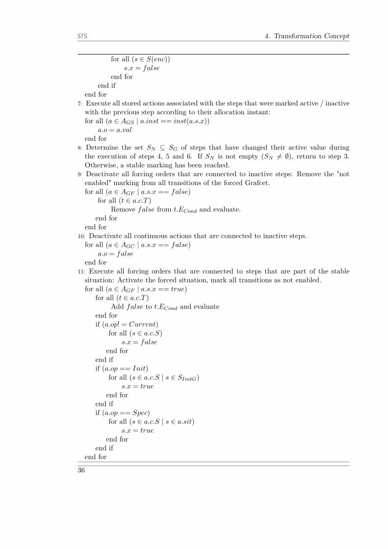
4. Transformation Concept
for all (s ∈ S(enc))s.x = false
end forend if
end for7: Execute all stored actions associated with the steps that were marked active / inactivewith the previous step according to their allocation instant:for all (a ∈ AGS | a.inst == inst(a.s.x))
a.o = a.valend for
8: Determine the set SN ⊆ SG of steps that have changed their active value duringthe execution of steps 4, 5 and 6. If SN is not empty (SN 6= ∅), return to step 3.Otherwise, a stable marking has been reached.
9: Deactivate all forcing orders that are connected to inactive steps: Remove the "notenabled" marking from all transitions of the forced Grafcet.for all (a ∈ AGF | a.s.x == false)
for all (t ∈ a.c.T )Remove false from t.ECond and evaluate.
end forend for
10: Deactivate all continuous actions that are connected to inactive steps.for all (a ∈ AGC | a.s.x == false)
a.o = falseend for
11: Execute all forcing orders that are connected to steps that are part of the stablesituation: Activate the forced situation, mark all transitions as not enabled.for all (a ∈ AGF | a.s.x == true)
for all (t ∈ a.c.T )Add false to t.ECond and evaluate
end forif (a.op! = Current)
for all (s ∈ a.c.S)s.x = false
end forend ifif (a.op == Init)
for all (s ∈ a.c.S | s ∈ SInitG)s.x = true
end forend ifif (a.op == Spec)
for all (s ∈ a.c.S | s ∈ a.sit)s.x = true
end forend if
end for
36

4.1. Grafcet Interpretation Algorithm
12: Execute all continuous actions that are connected to steps that are part of the stablesituation.for all (a ∈ AGC | a.s.x == false)
a.o = a.ECond
end for13: Return to step 2.
The most important aspect is the necessity of mutually exclusive concurrent transi-tions. Consider figure 4.1a. The Grafcet norm states that ‘Exclusive activation of aselected sequence is not guaranteed from the structure. The designer should ensure thatthe timing, logical or mechanical aspects of the transition-conditions are mutually exclu-sive.’[18, p. 33]. For the given figure, this means that when step 20 is active and signala becomes 1, both transition t1 and t2 fire and the steps 21 and 22 become active. Theinterpretation algorithm would yield the same result. According to the above quote, thisis in line with the norm, although not desired. If the designer intends such a "tokensplit", he shall use a synchronization as in figure 4.1d. In the case of figure 4.1b, one
(a) (b) (c) (d)
Figure 4.1.: Examples for the Modeling of Concurrent Transitions
has to distinguish between the Grafcet theory and the way the interpretation algorithmworks. According to the Algebra of Events, two independent signals can never occur atthe same time. For the example, this means that if signal a and b are independent, t1and t2 will never fire simultaneously and the behavior is well-defined. Given the imple-mentation of the interpretation algorithm on a PLC, however, it could happen that thesignals a and b change their value not at the same time, but during the same scan cycle.During step 2 and 3 of the algorithm, both transitions t1 and t2 would be marked asfireable and then fired in step 4, resulting in the situation where steps 21 and 22 areactive. To avoid such behavior, the following requirement has to be met:
Definition 4.1.1. The transition conditions of concurrent transitions have to be de-signed mutually exclusive to avoid unexpected token splits. (figure 4.1c)
Another important remark on the design of a Grafcet concerns conflicts in the allo-cation of signals. In figure 4.2 on the next page, the firing of transition t1 leads to theactivation of steps 30 and 31 and thus a conflict in the value of k. The norm has no ruleof how to handle such conflicts and states that ‘the designer shall ensure that two con-tradictory allocations cannot occur simultaneously’[18, p. 19]. In the intpretation as aCIPN, this case is covered as well. A CIPN has to be safe to be interpreted as a Grafcet.
37

4. Transformation Concept
One property of a safe CIPN is that for every pair of operations that can be active atthe same time, these operations need to be strongly compatible. This means that thesets of variables manipulated by operation OI needs to be disconnected from the setsof variables manipulated by operation OJ . Our interpretation algorithm however would
Figure 4.2.: Example for Concurrent Actions
not recognize such a conflict. All actions are executed one by one after one evolutioncycle. The output value of k would be determined by the last action that manipulatedthat value and thus depend on the execution order. In the case of our implementation(top-to-bottom, left-to-right execution), k would be 10. This can be desired, but thebehavior of a control program should be explicit, so that the following design restrictionapplies:
Definition 4.1.2. For every pair of stored actions that can be active at the same time,the sets of variables they manipulate need to be disjoint.
For continuous actions, such conflicts are not possible. The outputs of continuousactions are true if a corresponding action is active and false otherwise. If severalcontinuous actions try to manipulate the same output, it simply is true.Especially in the case of hierarchically structured Grafcets, the design restriction re-
garding stored actions seems very difficult to achieve. Theoretically, the designer has tocheck every possible system state, i.e., every possible situation over all partial-Grafcets,to ensure that no conflicts occur. ‘State explosion’ with extension of the program bymore and more partial-Grafcets comes to mind. Yet, in a real world control program,different hierarchically structured partial-Grafcets have different control tasks and thususually operate on a different set of signals and variables. This facilitates the handlingof the given restriction. In section 6.1, we give a brief outline on how static code analysiscan help in meeting the design restrictions.
4.2. Resulting Transformation ConceptFollowing the approach of implementing the Grafcet interpretation algorithm presentedin section 3.2.2, we need a boolean variable for every step and transition. To modelthe dynamic behavior according to the Grafcet interpretation algorithm for sequentialsystems, a standard set of methods represents each step of the algorithm. Table 4.1shows a mapping of these methods to the algorithm steps with a short comment on thefunctionality.
38
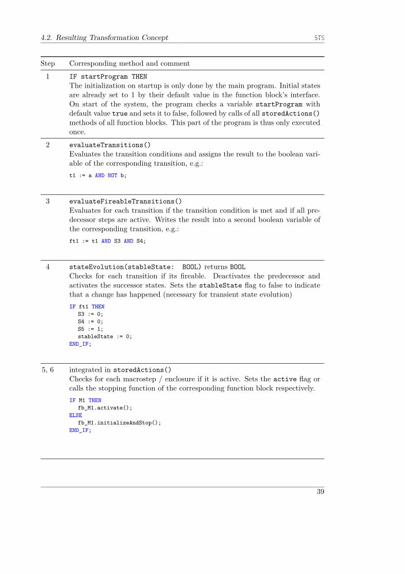
4.2. Resulting Transformation Concept
Step Corresponding method and comment
1 IF startProgram THENThe initialization on startup is only done by the main program. Initial statesare already set to 1 by their default value in the function block’s interface.On start of the system, the program checks a variable startProgram withdefault value true and sets it to false, followed by calls of all storedActions()methods of all function blocks. This part of the program is thus only executedonce.
2 evaluateTransitions()Evaluates the transition conditions and assigns the result to the boolean vari-able of the corresponding transition, e.g.:t1 := a AND NOT b;
3 evaluateFireableTransitions()Evaluates for each transition if the transition condition is met and if all pre-decessor steps are active. Writes the result into a second boolean variable ofthe corresponding transition, e.g.:ft1 := t1 AND S3 AND S4;
4 stateEvolution(stableState: BOOL) returns BOOLChecks for each transition if its fireable. Deactivates the predecessor andactivates the successor states. Sets the stableState flag to false to indicatethat a change has happened (necessary for transient state evolution)IF ft1 THEN
S3 := 0;S4 := 0;S5 := 1;stableState := 0;
END_IF;
5, 6 integrated in storedActions()Checks for each macrostep / enclosure if it is active. Sets the active flag orcalls the stopping function of the corresponding function block respectively.IF M1 THEN
fb_M1.activate();ELSE
fb_M1.initializeAndStop();END_IF;
39

4. Transformation Concept
Step Corresponding method and comment
7 storedActions()Checks for each step if its active and executes the corresponding stored action,e.g.:IF S5 THEN
output1 := 5;END_IF;
8 WHILE stableState := FALSE DOThe main program calls all stateEvolution functions of all function blocksrepeatedly in a while-loop. The stableState flag variable is the input andoutput parameter. The exit condition of the while-loop is that stableStateremains unchanged during one loop.
9 integrated in pullDownSignals()Removes the forcedFlag from forced Grafcets when the corresponding stepis not active anymore:IF NOT S5 THEN
fb_G1.setForcedFlag(FALSE);END_IF;
10 pullDownSignals()Sets all outputs of continuous actions to 0, e.g.: output10 := 0;
11 integrated in continuousActions()Carries out all necessary actions to move a forced partial-Grafcet to the forcedsituation and sets the forcedFlag to true to keep it there. For example, theforcing of a specific situation yields:IF S2 THEN
fb_G1.deactivateAllSteps();fb_G1.setForcedFlag(TRUE);fb_G1.activateStepS7();fb_G1.activateStepS8();
END_IF;
12 continuousActions()Checks for each state if its active and sets the output of the correspondingcontinuous action to true.IF S5 THEN
output10 := true;END_IF;
40

4.2. Resulting Transformation Concept
Step Corresponding method and comment
13 EOF programThe end of a program marks the end of a scan cycle.
Table 4.1.: List of methods corresponding to the steps of the Grafcet interpretation al-gorithm in section 4.1
This implementation includes some variations of the initial Grafcet interpretationalgorithm. For performance reasons, we changed the way how macrostep expansionsand enclosed partial-Grafcets are activated/deactivated (steps 5,6). In the algorithm, theentry-step / enclosed steps are activated on activation of their parent steps. Accordingly,all steps are deactivated on deactivation of their parent steps. Given the structure ofthe main program that calls all methods, this would mean that each if-statement of eachmethod would be evaluated, although the function block is not active. The results wouldbe correct since all if-statements would detect inactive steps, but the performance of theprogram might suffer. We improved this by introducing an active flag for macrostepexpansions and enclosed partial-Grafcets, which is set / unset together with the parentelement. The methods for state evolution and action execution are only executed underthe condition that the active flag is set.The same principle applies to the execution of fording orders. Once a forcing order
is active, it sets a forcedFlag within the forced function block. An active forcedFlagprevents the execution of the state evolution function. Setting all transitions to ‘notfireable’ would yield the same behavior but require more computations.All output variables of continuous actions are set to 0 in each cycle and then reset to
1 if a corresponding continuous action is executed. This is to ensure correct behaviorwhen macrosteps are traversed in a single transient evolution step. This variation doesnot affect the system behavior because the state of the variables is intermediate duringa scan cycle and only written to the actual output at the end of such a cycle.Furthermore, we merged the activation and deactivation of macrosteps and enclosures
into the method for stored actions and the forcing orders into the method for continuousactions. This decision is rather intuitive because it simplifies the program structure.The necessity of additional methods to model implicit links depends on the type of
partial-Grafcet. For the different types, these additional methods are:
Classical chart. A classical chart can always be a forced Grafcet and thus needs toprovide corresponding methods:
• activateStateS*(): Necessary to activate steps of a forced situation. Since aforced Grafcet does not know about its possible forced situations, this method hasto be provided for every step.• activateInitSituation(): Necessary to activate the initial situation (not knownfrom the outside)
41

4. Transformation Concept
• deactivateAllSteps(): First step in bringing the function block to the forcedsituation.• get/set forcedflag: Getter and setter for the forcedflag that prevents transi-
tions from firing.
Macrostep expansion:
• activate(): Sets the active flag to true.• initializeAndStop(): Activates the entry step and sets the active flag to falseso that no transitions fire and no actions execute anymore.• getFinishedFlag(): Returns true if the exit step of the macrostep expansion isactive. This function has to be part of the fireability condition that succeeds themacrostep.
Enclosed partial-Grafcet
• activate(): Sets the active flag to true.• initializeAndStop(): Activates all enclosed steps and sets the active flag tofalse so that no transitions fire and no actions execute anymore.
This method-oriented approach requires a coordinator that repeatedly calls the meth-ods of the several function blocks, i.e., a Structured Text representation of the Grafcetinterpretation algorithm. We shall refer to this program as the main program in thecontext of this work. Listing 4.9 shows a main program that coordinates one simplepartial-Grafcet G1.IF startProgram THEN
startProgram := FALSE;fb_G1.storedActions();
END_IF;
fb_G1.evaluateTransitions();
globStableState := FALSE;WHILE globStableState = FALSE DO
globStableState := TRUE;fb_G1.evaluateFireableTransitions();globStableState := fb_G1.stateEvolution(stableState := globStableState);fb_G1.storedActions();
END_WHILE;fb_G1.pullDownSignals();fb_G1.continuousActions();
Listing 4.9: Example of the Main Program in Structured Text
On the implementation level, the main program is the POU that is linked to the PLCtask manager.An important aspect of the transformation concept is the evaluation order of methods
and elements. Since the PLC works in a sequential way and executes the programline-by-line, the evaluation of Grafcet elements depends on their position in the source
42

4.2. Resulting Transformation Concept
code. When the design restrictions presented in section 4.1 are met, the evaluation orderdoes not have an effect on the dynamic behavior of the Grafcet. Nevertheless, we haveto define an execution order that follows a defined rule to ensure transparent programbehavior. An obvious approach would be to evaluate the elements according to theirposition on the chart, e.g., from top to bottom and from left to right. For the example infigure 4.1b and the step evaluateTransitions, this means that the line that evaluatesthe transition condition of t1 is put above the line for t2. The Grafcet syntax itself doesnot include information about the position of elements. This information needs to bedirectly derived from the editor. The activation of steps of a forced situation dependson the ordering of steps in the forcing order, which is evaluated from left to right. Theexecution order is also important for the main program. The order in which the methodsof the different function blocks are called has to follow a certain principle. We simplyused the internal ordering of charts in the Grafcet editor, since the syntax does notinclude any priority measure as well. We pick up this aspect in section 6.1 where wediscuss how the ordering can be improved.
4.2.1. Transformation Procedure
As described in the introduction, the general objective of the transformation is to createa separate POU, i.e., a function block, for each partial-Grafcet. Irrespective of the typeof Grafcet chart, each function block consists of the set of basic methods in table 4.1.In addition to that, each function block has to provide the additional set of methodsdepending on its type. We refer to a function block that includes a set of methods withempty bodies as a shell. In appendix A.1.2, we show the shells for the different types ofpartial-Grafcets.
Figure 4.3.: Process Steps of Transformation Concept
Our aim is to develop a one-to-one correspondence transformation approach. We limitthis one-to-one correspondence to a unidirectional transformation from Grafcet to IEC61131-3 for this work, although the final concept can also be applied to a bidirectional
43
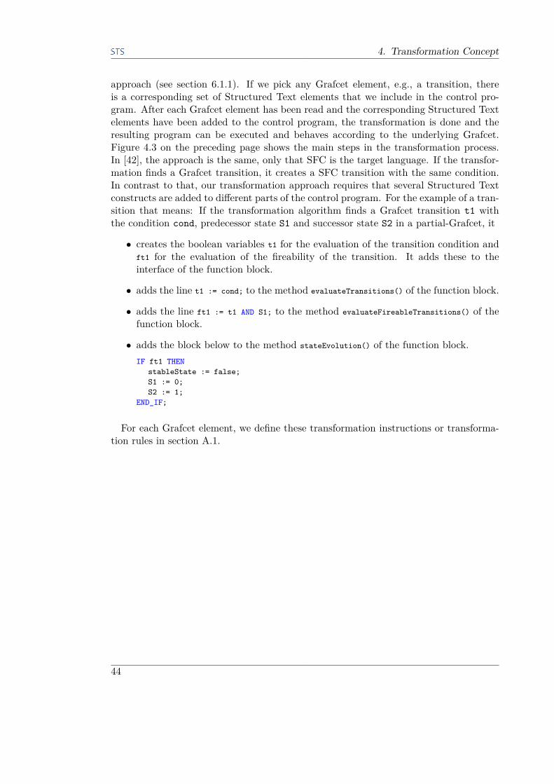
4. Transformation Concept
approach (see section 6.1.1). If we pick any Grafcet element, e.g., a transition, thereis a corresponding set of Structured Text elements that we include in the control pro-gram. After each Grafcet element has been read and the corresponding Structured Textelements have been added to the control program, the transformation is done and theresulting program can be executed and behaves according to the underlying Grafcet.Figure 4.3 on the preceding page shows the main steps in the transformation process.In [42], the approach is the same, only that SFC is the target language. If the transfor-mation finds a Grafcet transition, it creates a SFC transition with the same condition.In contrast to that, our transformation approach requires that several Structured Textconstructs are added to different parts of the control program. For the example of a tran-sition that means: If the transformation algorithm finds a Grafcet transition t1 withthe condition cond, predecessor state S1 and successor state S2 in a partial-Grafcet, it
• creates the boolean variables t1 for the evaluation of the transition condition andft1 for the evaluation of the fireability of the transition. It adds these to theinterface of the function block.
• adds the line t1 := cond; to the method evaluateTransitions() of the function block.
• adds the line ft1 := t1 AND S1; to the method evaluateFireableTransitions() of thefunction block.
• adds the block below to the method stateEvolution() of the function block.IF ft1 THEN
stableState := false;S1 := 0;S2 := 1;
END_IF;
For each Grafcet element, we define these transformation instructions or transforma-tion rules in section A.1.
44

5. Prototypical Implementation ofTransformation Concept
The work on this thesis includes the development of a prototypical transformation pro-gram that shall serve as a proof-of-concept for the preceding considerations. Section 5.1gives an overview about the tool landscape we choose to embed the transformationprogram. The actual implementation is explained in section 5.2. The basis of the trans-formation program are the code shells for function blocks and the transformation rulesin section A.1. This chapter closes with a discussion about the transformation program’scapabilities (section 5.4). This includes the description of test scenarios we chose to testboth the transformation program and the execution algorithm for correctness. We alsodiscuss the features of Grafcet that have not yet been added to the program and thatare part of future implementations.Figure 5.1 is an extension to the process diagram in figure 4.3 and shows the different
tools and file formats used during the transformation process.
Figure 5.1.: Tools and File Formats used During Transformation
5.1. Tool SupportPart of the work of Schumacher in [42] was the development of a Grafcet-editor basedon Microsoft Visio (MS Visio) and a prototype for a transformation program writtenin C#. Both programs serve as a basis for the transformation program that has beendeveloped during the work on this thesis. This section gives a brief overview of theirfunctionality. For a more detailed explanation, refer to [42] and [41].
5.1.1. IEC 61131-3 Software Development Environment
In the field of automation software development tools, well-established programmingtools include the following: STEP7 by Siemens [44], Codesys by 3S-Software [1], Multi-prog by Phoenix Contact Software [33] or Control Build by Dassault Systèmes [9]. TheIEC 61131-3 is a standard that harmonizes the design of industrial control programs. Assuch, a transformation program that chooses one of the defined programming languagesas a target for the implementation should be able to produce code that runs on any
45

5. Prototypical Implementation of Transformation Concept
IEC 61131-3 software development environment. However, the tools differ slightly fromanother. None of the above tools offers full support for the latest version of the IEC61131-3. Codesys 3.5 offers an implementation of object-oriented extensions for func-tion blocks, but does not include the new POU-type Class. Furthermore, these object-oriented extensions have been in place since 2007 [47], six years before the correspondingnorm introduced these features. That explains why the syntax of object-oriented func-tion blocks in Codesys differs slightly from the norm, as we will explain in the nextsection. The current releases of Multiprog and Control Build do not support any ofthe new features at all. On that basis, we chose Codesys as a target software develop-ment environment. The next section explains how the choice of an input interface forthe transformed control program leads to further need for tailoring the transformationprogram to Codesys.
5.1.2. PLCopenXML
To integrate the automatically generated ST-code into the IEC 61131-3 software de-velopment environment, we need a comprehensive and preferably standardized andvendor-independent interface. PLCopenXML is a data exchange format provided bythe PLCopen organization which meets these requirements. PLCopen is a vendor- andproduct-independent worldwide association, whose prime mission is to develop and pro-mote the use of international standards in the field of industrial automation [36]. Acore activity of PLCopen is the certification of IEC 61131-3 compliant programmingsystems. However, the certification itself includes several levels (Base Level, Confor-mity Level, Reusability Level), that guarantee conformance with the norm to a certaindegree, but still leave space for vendor- and tool-specific implementations. As the PLC-manufacturers are keen on keeping a unique selling proposition and thus a competitiveadvantage in the market, these vendor-specific modifications are common practice. Assuch, it is not possible to simply use a set of standardized project files that can be usedand compiled by several different software development tools. To be able to exchangeprograms, libraries, and projects regardless of such often minor implementation differ-ences, the PLCopen organization decided on XML (eXtended Markup Language) as theappropriate data language and founded a workgroup named TC6 for XML. The resultof the workgroup’s effort was a first version of an XML schema published in 2005 asversion 1.01. The current version has the number 2.0 and was published in 2008 [37].More recent efforts on data exchange formats in the automation domain include the workon AutomationML, an initiative started in 2006 by an industry consortium and researchinstitutes [2]. AutomationML does not intend to be a completely new data format, butto combine existing data formats into one convenient tool. These existing tools includeCAEX[21] as a top-level format for storing the plant topology and communication in-formation, COLLADA[25] for geometry and kinematics and PLCopenXML for behaviorand sequencing descriptions. AutomationML has successfully been certified as the inter-national standard IEC 62714-2 "Engineering data exchange format for use in industrialautomation systems engineering - Automation markup language - Part 2: Role classlibraries" in 2015 [17]. The very recent certification date together with the overall aim
46

5.1. Tool Support
of AutomationML and the industry impact of the involved parties (i.e., Daimler, ABB,KUKA, Rockwell, Siemens among others) allow for the conclusion that AutomationMLhas the potential to become the data exchange format of choice for future automationsoftware development tools. However, all known engineering tools do not yet support theusage of AutomationML with dedicated import / export functionality. We thus focusedon PLCopenXML as a target format for the transformation algorithm.The PLCopenXML schema maps the structure of an IEC 61131-3 program or POU
into a corresponding XML-tree. Figure 5.2 shows the structure of a POU in PLCopenXML.It consists of a set of attributes like name and type of POU, an interface that containsthe declaration of all variables and a body. If SFC is used, a POU has an additional setof actions and transitions. This structure is following the current standard of software
Figure 5.2.: PLCopenXML Representation of an IEC 61131-3 POU
development tools rather than strictly following the norm. For the declaration of simplefunction blocks in the ST language, the IEC 61131-3 suggests one coherent code blockthat includes a variable declaration block in the beginning, followed by the functionblock’s body. The norm does not explicitly mention a split of a POU into an interfaceand a body. Yet, in all known IEC 61131-3 software development tools, the declarationpart and the body are two different entities in two different editor windows.The current version of PLCopenXML is based on the second edition of the IEC 61131-3
from 2003, so there is no support for the new object-oriented features that were intro-duced in the latest edition. As we mentioned before, Codesys 3.5 does provide theobject-oriented extensions for function-blocks. However, the structure of the implemen-tation differs from the norm, which claims:
47
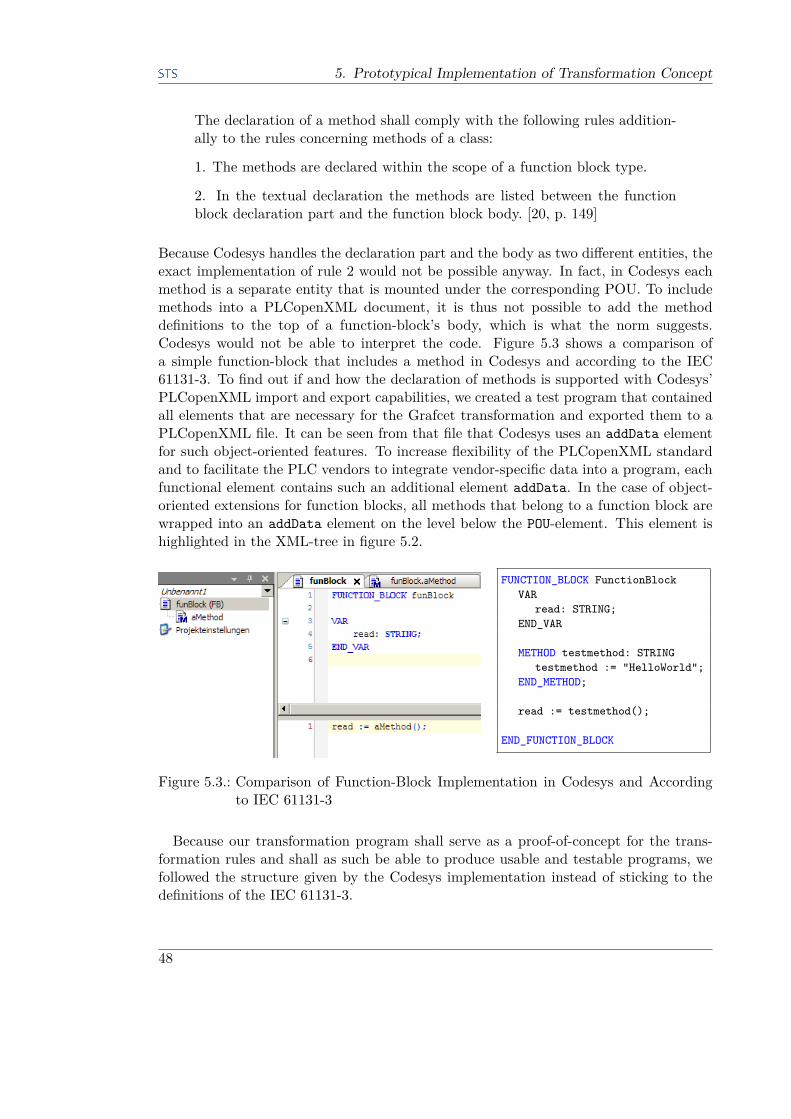
5. Prototypical Implementation of Transformation Concept
The declaration of a method shall comply with the following rules addition-ally to the rules concerning methods of a class:
1. The methods are declared within the scope of a function block type.
2. In the textual declaration the methods are listed between the functionblock declaration part and the function block body. [20, p. 149]
Because Codesys handles the declaration part and the body as two different entities, theexact implementation of rule 2 would not be possible anyway. In fact, in Codesys eachmethod is a separate entity that is mounted under the corresponding POU. To includemethods into a PLCopenXML document, it is thus not possible to add the methoddefinitions to the top of a function-block’s body, which is what the norm suggests.Codesys would not be able to interpret the code. Figure 5.3 shows a comparison ofa simple function-block that includes a method in Codesys and according to the IEC61131-3. To find out if and how the declaration of methods is supported with Codesys’PLCopenXML import and export capabilities, we created a test program that containedall elements that are necessary for the Grafcet transformation and exported them to aPLCopenXML file. It can be seen from that file that Codesys uses an addData elementfor such object-oriented features. To increase flexibility of the PLCopenXML standardand to facilitate the PLC vendors to integrate vendor-specific data into a program, eachfunctional element contains such an additional element addData. In the case of object-oriented extensions for function blocks, all methods that belong to a function block arewrapped into an addData element on the level below the POU-element. This element ishighlighted in the XML-tree in figure 5.2.
FUNCTION_BLOCK FunctionBlockVAR
read: STRING;END_VAR
METHOD testmethod: STRINGtestmethod := "HelloWorld";
END_METHOD;
read := testmethod();
END_FUNCTION_BLOCK
Figure 5.3.: Comparison of Function-Block Implementation in Codesys and Accordingto IEC 61131-3
Because our transformation program shall serve as a proof-of-concept for the trans-formation rules and shall as such be able to produce usable and testable programs, wefollowed the structure given by the Codesys implementation instead of sticking to thedefinitions of the IEC 61131-3.
48

5.1. Tool Support
5.1.3. Microsoft Visio Grafcet EditorAll known Grafcet editors use proprietary file formats to store the information aboutthe designed Grafcet charts. A new editor had to be designed that stores the Grafcetinformation in an open file format. MS Visio is a tool for the design of graphs, networksand maps that offers the implementation of custom shape libraries and allows extensivemodifications via its Visual Basic for Applications (VBA) module. Furthermore, it ispossible to save a MS Visio document in the XML file format .vdx (Visio XML Format).With a custom shape library that covers all elements defined in the Grafcet specification(refer to section 2.1 on page 5), MS Visio can be used to design Grafcet charts. Thecurrent implementation of the shape library has a few restrictions:
• The forcing of a partial Grafcet allows the forcing of a maximum of three steps.
• An enclosure can only enclose one partial Grafcet, thus leading to a 1:1 relation ofenclosures to enclosed partial-Grafcets instead of 1:n.
In this work, MS Visio with the integrated Grafcet shape library is referred to as Grafceteditor. The editor strictly follows the naming convention of steps and partial Grafcets ac-cording to the norm [18]. This is particularly important for our transformation program,which uses these names to distinguish between the different types of partial-Grafcets.A partial-Grafcet with the name X2/* is an enclosed partial-Grafcet that belongs tothe enclosing step 2. A partial-Grafcet with the name M* is a macrostep expansion ofthe macrostep with name *. If neither of these properties is met, the partial-Grafcetis a classical chart. A consistency check warns the user if elements are not properlyconnected and if all connected Grafcets actually exist. This consistency check is purelysyntactical. It is possible to design and export erroneous and/or incomplete Grafcets.The user has to make sure that the Grafcet is correct. A static analysis of Grafcet couldbe done using the exported Grafcet information and is part of ongoing research (seesection 6.1).
5.1.4. Read-Module of Transformation ProgramThe decision for C# as an implementation language for the transformation programresults mainly from the fact that C# is used in the author’s institute to teach object-oriented programming to students. Thus all involved programmers had a commonground in C# programming experience. With Visual Studio [29] and .NET [28], Mi-crosoft provides a powerful framework for the development of C# applications. Thestructure of the transformation program is based on a Grafcet-based internal object-model. The class XMLReader takes the Visio XML file as a stream, identifies the typeof element and creates the corresponding object in the internal object model. The rootelement document of this object model contains a container (i.e., a List in this case)of page objects, where each page represents a partial-Grafcet. All information aboutGrafcet-elements and their links is stored in specific lists and objects inside such a page-object. Figure 5.4 on the next page shows a simplified UML diagram of the internalobject model. The transformation process consists of three main steps, represented by
49

5. Prototypical Implementation of Transformation Concept
Figure 5.4.: Simplified UML-Diagram of Internal Object Model
three classes. The XMLReader class reads the Visio XML file according to the abovedescription. The class XMLConverter connects all objects using the unique VisioID ofeach element. Furthermore, it carries out the normalization of hierarchical elementsinto one single Grafcet. The last task is the preparation of all objects so that they candirectly be transferred into PLCopenXML elements without further conversion duringthe transformation. The class PLCopenXMLWriter then takes all relevant lists of state,transition and action objects and creates the corresponding XML-elements.To implement our transformation algorithm, we extended the internal object model
that is based on Grafcet by an additional object model that serves as a representation foran IEC 61131-3 function-block. A functionBlock objects contains an interface with allinput-, output- and internal variables and a list of assigned methods. Figure 5.5 on thefacing page shows the extensions we made to the internal object model in a simplifiedUML-diagram. The XMLReader class did not need any modifications. The Converterand PLCopenXMLWriter class were replaced by our own implementation.
5.2. Implementation of Converter ClassWe created a class named Preprocessor for the transformation of the Grafcet elementsinto their corresponding Structured Text code fragments according to the transformationrules in section A.1.While the declaration of variables in PLCopenXML is done with separate XML-
elements, a method’s body consists of only one string. To create and fill the methodsof each function block with the code fragments of Grafcet elements, we make extensive
50

5.2. Implementation of Converter Class
Figure 5.5.: Simplified UML-Diagram of Extensions to the Internal Object Model
use of string concatenation. This is particularly important because we need to makesure that we stick to the evaluation order defined in section 4.2. For our program, thatmeans the order in which we add code fragments to the body member of a method objectdetermines the evaluation order on the PLC.The object model uses Lists for object collections, e.g., a list of transition objects
inside a page object. We use the foreach loop to iterate through these lists and read andprocess Grafcet elements. To ensure that we stick to the evaluation order, we use LINQ(ref. to section 5.3) to sort the list elements according to their position on the chart. TheGrafcet syntax itself only contains information about the connection of elements, butnot about their position since such data is not important for the execution of Grafcet.To implement something like a "from top to bottom from left to right" evaluation order,we need to be tool-specific and use the anchor points of the Visio shapes on the chart.This information is stored in the internal object model and can be used to sort thelist. For the example of the list of transitions in a page, listing 5.1 is the correspondinginstruction that sorts the list from top to bottom and from left to right.
List<Transition> sortedTransitionList = functionBlock.Page.TransitionList.OrderBy(x => x.Position.y).ThenBy(x => x.Position.x).ToList();
functionBlock.Page.TransitionList = sortedTransitionList;
Listing 5.1: Example of the sorting of transition objects according to their position
An important requirement for the correct functioning of this sorting strategy is thealignment of elements in the editor:
• Concurrent transitions that succeed the same step need to be horizontally aligned.
• Multiple actions for the same step need to be vertically aligned.
51

5. Prototypical Implementation of Transformation Concept
The UML-activity diagram in figure 5.6 shows the transformation process of the controlprogram. It is based on the formal Grafcet definitions in section 2.1.3 on page 12 andthe transformation rules depicted in section A.1 on page 63. The subcharts for thetransformation of steps and actions are added in the appendix.
Figure 5.6.: Activity Diagram of Transformation Program - Subcharts in Appendix
A great deal of complexity in the program arises from the difference of variable dec-larations. The Grafcet norm does not require any separate variable declaration. A newvariable can just be introduced and used. The type of the variable has to be derivedfrom its usage (e.g., a signal in a continuous action is a bool). Furthermore, the Grafcet
52

5.3. Implementation of PLCopenXMLWriter Class
standard does not provide any definition about the available variable types and theirsemantics. When referring to the type of a variable, the standard uses the expressionsboolean and numeric with no further explanation. We thus assume that the designerof a Grafcet uses the variable types and their semantics of the target implementation,i.e., the IEC 61131-3 for our work. The MS Visio editor was extended by the possibil-ity to declare IEC 61131-3 compliant variables in a separate file and use them in theGrafcet. The IEC 61131-3 requires the declaration of variables for each function blockseparately. Global variables can be declared in a separate entity, but need to be declaredas VAR_EXTERNAL if they are used in a function block. The variable file applies to allpartial-Grafcets, so the program still needs to identify the variables used in the specificpartial-Grafcet. The current implementation extracts all variables from transition con-ditions and actions during the transformation process, extracts the variable type fromthe variable file, and adds the variables to the variable list of the function block (secondto last step in figure 5.6). Future work on the editor or even on the Grafcet standarditself should consider including variable declarations for each partial-Grafcet. Whenconstructing a control program, the designer should be aware of the available signalsanyway. A variable declaration part (e.g., an additional element) could even simplifythe design of a Grafcet because all available signals and variables are visible on the chart.
5.3. Implementation of PLCopenXMLWriter ClassTo construct the PLCopenXML file, the function block objects of the internal objectmodel need to be transferred into the corresponding XML-structure. With the LanguageIntegrated Query (LINQ)[27], the Microsoft .NET framework provides a convenient dataquery language that can be used to read and manipulate XML files. The usage of LINQin the context of automation is discussed in great detail in [4]. Since the structure ofthe function block and method objects is already very similar to the PLCopenXMLstructure, the transformation is straightforward. Each XML element is described by anew instance of the XStreamingElement class. Listing 5.2 shows an example of howa method without parameters and return values is transformed into a correspondingPLCopenXML structure.new XElement(ppx + "addData",from method in functionBlock.MethodListwhere !method.InputVars.Any() && method.ReturnType == nullselect new XElement(ppx + "data",
new XAttribute("name", codesys.ToString() + "method"),new XAttribute("handleUnknown", "implementation"),new XElement(ppx + "Method",
new XAttribute("name", method.Name),new XElement(ppx + "interface"),new XElement(ppx + "body",
new XElement(ppx + "ST",new XElement(xhtml + "xhtml",
method.Body)
)
53

5. Prototypical Implementation of Transformation Concept
),new XElement(ppx + "addData")
))
Listing 5.2: Example of the Construction of a PLCopenXML Element for a Method
5.4. Test and OutlookThe work on this thesis includes the development of the transformation concept ofGrafcet charts into Structured Text function blocks and the development of a programthat does this transformation automatically. The test of the program follows two maingoals:
• Simulate the produced IEC 61131-3 Structured Text code and check the dynamicbehavior against the Grafcet specification (check if the concept is right).
• Check if the transformation program fulfills the transformation rules (check if thetransformation is done right).
Figure 5.7.: Test Case Concept for the Combination of Hierarchical Elements
Since all Grafcet elements are read and transformed separately, checking the correctapplication of the transformation rules means finding a test suite that contains a com-bination of Grafcet elements such that each transformation rule is applied at least once.The transformation rules are independent from each other, so if this test succeeds, thesecond test goal can be considered achieved. Referring to the UML activity diagram infigure 5.6, the aim is to find a test suite so that the transformation program traverseseach branch of the diagram at least once. The transformation rules for some elementsdepend on the type of partial-Grafcet to which they belong. Thus, a comprehensivetest suite needs to contain a combination of all these elements in all types of partial-Grafcets. We used a set of 9 test cases that include a two-level hierarchical structuringof partial-Grafcets. These test cases consist of each possible combination of the hierar-chical elements macrostep, forcing order and enclosure. The graph in figure 5.7 showsthe three test cases with a forcing order at the highest level. All tests were successful,i.e., all transformation rules were applied correctly.
54

5.4. Test and Outlook
The only manual task that needs to be done in the transformation process is the cre-ation of a configuration inside Codesys. Codesys offers an integrated Soft-PLC, namedCodesys Win Control V3, that emulates an industrial controller under Windows. Aconfiguration that makes use of this Soft-PLC is the default setting in Codesys. Us-ing this configuration, it was possible to read the Visio-XML files, transform them intoPLCopenXML files and import these into the Codesys software development. The re-sulting control programs can be executed without any further manual modifications.To validate the dynamic behavior of the transformed code, we used these simulation
capabilities and the same set of test cases and focused on the following aspects:
• Transient state evolution during one execution cycle
• Evaluation of stored actions and skipping of continuous actions during one execu-tion cycle
• Correct activation / deactivation of partial-Grafcets with their corresponding hi-erarchical elements
• Correct state of the program on start of the application
The integrated debugger enables the user to watch the values of all variables, forcevariables to specified values and execute the program for only one PLC cycle. We usedthese tools to bring the program to a specific state (i.e., to a specific Grafcet situation),select an input image and execute one cycle. We compared the resulting state of theprogram and the output image to the Grafcet situation we calculated for the given inputs.All tests we made for the current implementation scope of the program were successful,i.e., the state of the program was equal to the Grafcet situation we calculated.Appendix A.3 contains yet another example for a Grafcet with hierarchical elements
(i.e., a macrostep and an enclosure). It also contains a description of the calculateddynamic behavior and shows the program structure of the transformed IEC 61131-3program in Codesys.
5.4.1. Events and Timed GrafcetsThe current version of the program and the evaluation algorithm do neither includeevents nor time constraints. When introducing these timed properties, the differentnature of Grafcet and PLC program evaluation has to be considered again. While inGrafcet, the event ↑a occurs when the signal a actually changes its value from 0 to 1,the PLC interprets the same event when a has changed its value at some point betweentwo scan cycles. This can lead to a time difference of a maximum of two cycle duration.The same difference applies for timed actions and constraints. If a timed signal expiresjust after its value has been evaluated, it will stay active for the duration of one programcycle until its evaluation is done again.With these differences in mind, [42] shows that it is generally possible to extend the
program by event handling and timed variables. The IEC 61131-3 offers standard func-tion blocks for reoccurring tasks like edge detection and time delays. For the detection
55

5. Prototypical Implementation of Transformation Concept
of rising and falling edges of events, the R_TRIG and F_TRIG function blocks can be used.They take the signal in question as input and store its value in an internal flag. At thebeginning of each cycle, the new value of the signal is compared to its old one and the re-sult of the comparison is written to the function block’s output Q. John and Tiegelkampmention explicitly that this means that only edges that occur at intervals of at least oneprogram cycle can be detected [22]. Figure 5.8 shows how a function block for rising edge
// VARR_TRIG_INST: R_TRIG;a : BOOL;t1 : BOOL;
// evaluateTransitionsR_TRIG_INST(CLK := a);t1 := R_TRIG_INST.Q;
Figure 5.8.: Example of the Usage of Edge Detection Function Blocks
detection is implemented according to the transformation rules. The function block’sinput has to be set to the variable / signal a, which could be done anywhere and onlyonce. The output signal of R_TRIG_INST then determines the transition condition. Fortimed variables, the TON and TOF function blocks offer on- and off-delays for variables.These are used in the same way as the edge detection function blocks.The implementation of events and timed variables is planned and was left out of the
scope of this thesis mostly because of the complexity of extracting variables and theirtypes from signals and actions.
56

6. Conclusion
While it is common practice in desktop application development, the use of model-driven engineering is still at a very early stage in the domain of automation solutiondevelopment. Current research is still at the stage of finding appropriate modelinglanguages and use-case scenarios.Recent works suggest to use Grafcet, a graphical specification language for the control
part of automation systems, to be used as a specification model. The main power ofGrafcet is, aside its graphical and thus intuitive way of designing automation controlprograms, the possibility of structuring a complex control task into smaller units (i.e.,partial-Grafcets) that synchronize each other with the use of hierarchical elements. To beable to execute a control program that has been specified in Grafcet on a PLC, it needsto be interpreted as a control program in one of the programming languages defined inthe IEC 61131-3 industrial norm. The IEC 61131-3 contains Sequential Function Charts,a programming language that is said to be based on Grafcet. Most previous efforts tofind a systematic transformation approach of Grafcet specifications into IEC 61131-3implementations focus on a transformation into SFC. However, the SFC syntax doesnot provide equivalent elements for the hierarchical elements of Grafcet. The resultingtransformations either ignore hierarchy, or they transform all hierarchical elements intoone single Grafcet before the transformation.The aim of this thesis was to find a transformation approach of Grafcet specifications
into an IEC 61131-3 implementation that could preserve the hierarchical structure ofthe Grafcet. In section 3, we analyzed the potentials of the IEC 61131-3 programminglanguages as a target language for the transformation. Next to the rather obvious choiceof SFC, we also found the usage of Structured Text to be a promising approach. Wedefined four quality metrics that a transformed program shall meet and used these fora detailed analysis of both languages with a focus on the implementation of hierarchicalelements. This analysis revealed that the modeling of Grafcet’s hierarchical elementswith SFC results in very complex charts. Furthermore, the semantics and dynamicbehavior of SFC are difficult to adapt to Grafcet’s dynamic behavior and are furthermorevendor-dependent. We favored an approach in Structured Text, where the dynamicbehavior of Grafcet can be encapsulated in corresponding methods.On that basis, we developed a Grafcet interpretation algorithm for sequential systems
in section 4. Grafcet is a parallel language synchronized on external events. On occur-rence of an external event, the state of a Grafcet evolves immediately and all necessaryactions are executed simultaneously. A PLC in contrast works in a sequential way andis executed in cycles. That means that a PLC program evolves in each new cycle, whileall necessary actions are executed one-by-one. Thus, to be able to interpret a Grafcetspecification on a PLC, such an interpretation algorithm is necessary. With the algo-rithm in place, we defined transformation rules that translate each Grafcet element intoa corresponding set of Structured Text code fragments. The resulting control programpreserves the hierarchical structure of partial-Grafcets with the use of corresponding IEC61131-3 function blocks.
57

6. Conclusion
To be able to test the developed transformation concept, we built a prototypical trans-formation program in section 5. The prototype was built on top of an existing programfor the transformation of Grafcet into SFC without hierarchical elements. The programmakes use of a Grafcet editor based on Microsoft Visio and outputs the transformed IEC61131-3 Structured Text program using the PLCopenXML file format. We were ableto import this file into the widely used automation software development environmentCodesys, where we could test the program on a Soft-PLC. In a first iteration, we tested ifthe program implements all transition rules correctly. Secondly, we defined a set of testcases to check the dynamic behavior of the transformed IEC 61131-3 control programagainst the manually computed behavior of the corresponding Grafcet. All tests weresuccessful.
6.1. Future Work
The validation of the current transformation concept has been done with a series of teststhat focused on a number of dynamic properties, but were selected rather intuitively. Itis desirable to undertake a structured test approach to be able to have a qualitative andquantitative measure about the concept’s correctness. Another interesting approach interms of concept validation would be the use of model checking techniques on the basisof the interpretation of Grafcet as a control interpreted Petri net as in [26].Future work on the implementation scope of the prototype should focus on the in-
tegration of events and timed properties as in section 5.4.1. Another important aspectis the evaluation order of Grafcet elements in the transformed Structured Text code.Currently, the elements of a partial-Grafcet are evaluated according to their positionon the chart, while the order of the partial-Grafcets themselves is determined by theircorresponding VisioID which is related to their creation timestamp. Especially the latteris a rather implicit property and not obvious to the designer. It would be desirable tobe able to define an explicit ordering within the Grafcet editor, e.g., by introducing apriority measure.One main advantage of model-driven engineering using formal methods is the possi-
bility to use static code analysis, i.e., applying mathematical methods to the model tocheck for general safety properties (e.g., deadlocks, unbounded loops) and user-definedconstraints and properties. The translation of Grafcet into CIPN in [42] enables theusage of existing CIPN static code analysis tools. These could be used to check if thedesign requirements that we defined in section 4.1 are met before a transformation isundertaken.Currently, all tests of the transformed IEC 61131-3 implementation are done in Codesys.
Some aspects of the transformation, i.e., the structure of the PLCopenXML file, aretailored to that tool. It can be assumed that new releases of other control software de-velopment environments will include the object-oriented extensions of function blocks ofthe new IEC 61131-3 and also implement a PLCopenXML import / export functionality.Changing the structure of the resulting PLCopenXML file of the prototype is easy toachieve, since only one class needs to be altered / extended. Thus, the transformation
58

6.1. Future Work
prototype should be extended to support all new releases of other software developmentenvironments.In the long term, the transformation concept could even be the basis of an integrated
Grafcet editor within the PLC development environments. Since Grafcet is part of thecurriculum of technicians in Germany, it is desirable to adopt Grafcet into an integratedengineering process.An interesting extension of the transformation program would be the backwards trans-
formation of the IEC 61131-3 program back into a Grafcet representation, as we describein section 6.1.1.
6.1.1. Possibility of Bidirectional Transformation
One of the biggest advantages of the Structured Text approach over most of the otherdiscussed ways to transform Grafcet into an IEC 61131-3 implementation is the possibil-ity of a bi-directional transformation approach, while preserving the original structureof the Grafcet. The process of transforming an existing implementation back to a spec-ification model is called reverse engineering and is part of ongoing research because ofthe wide use of different and sometimes even ancient programming languages in theautomation domain [3]. The necessity for such a backwards transformation results fromthe fact that minor changes to the control program are usually done directly in the codeby technicians. These changes typically include additional transition conditions or thechange of output values, caused by forgotten or failed actors and sensors in the plant.When the original model is used as a basis for the development of other or additionalcontrol programs, it is important that such small modifications are updated in the modelas well. An automated transformation approach facilitates these updates and preventsthe need for manual comparison of current program and original model. Referring to thewaterfall model in the introduction (figure 1.1 on page 1), a bidirectional transformationapproach enables the system model (i.e., the Grafcet specification) to conduct the SLDCalong all stages, including deployment and maintenance.Transforming a state machine back into a Grafcet is a straightforward task. The
easiest way would be to interpret each state as a step, each transition function as atransition condition and each output as a continuous action. However, constructing theoriginal Grafcet with the hierarchical structure from a state machine is not possible.The normalization approach in [42] makes it very difficult to transform the SFC imple-
mentation back to Grafcet. The transformed implementation does not include informa-tion about the number of partial-Grafcets that have been merged into one global Grafcet.This means that one does not know how many elements need to be extracted from theglobal Grafcet in order to gain the previous hierarchical structure of the underlyingGrafcet before the transformation. While the beginning and end of Macrostep expan-sions are still identifiable via the unique names of the entry- and exit-step, remodelingenclosed and forced Grafcets out of the global Grafcet is a very difficult task.For the Structured Text approach, only the interfaces and some methods need to be
evaluated to construct the original Grafcet. The following list is an informal descriptionthat could be the basis of a transformation algorithm. It anticipates the naming of ele-
59

6. Conclusion
ments from the prototypical transformation program in section 5.2.
For each function block...
1. create a partial-Grafcet with the name of the function block.
2. read the interface. Create a step for each variable that starts with a capital S, Mor E. Create a transition variable for each variable that starts with a capital T.
3. read the method "evaluateTransitions" line by line. find the transition with nameleft-hand-side of the expression, add the right-hand-side as its transition condition.
4. read the method "stateEvolution" if-statement per if-statement. Find the transitionwith name if-condition. Add all steps that are set to 0 as preceding and all stepsthat are set to 1 as succeeding to the transition.
5. read the method "continuousActions" if-statement per if-statement. Create a con-tinuous action. Link the action to the step with name if-condition. Compare thebody to transformation rules 12 to 15. If one of the rules applies, change the ac-tion into the respective forcing order. Else, add the body of the if-statement tothe action’s body.
6. read the method "storedActions" if-statement per if-statement. If the body lookslike transition rule 4 or 5 and the if-condition contains a capital M, find the cor-responding step with name if-condition and change it into a macrostep. If thebody looks like transition rule 4 or 5 and the body contains a capital S, find thecorresponding step with name if-condition and change it into an enclosure. In allother cases, create a stored action and link it to the step with name if-conditionand add the body of the if-statement to the action’s body.
7. If the function block’s name contains a capital X (i.e., it is an enclosed Grafcet),read the method "initializeAndStop" line per line. Mark all steps that are set to 1with an asterisk in the Grafcet.
The order of the lines and if-statements in the respective method is determined by theposition of these elements in the Grafcet. If the information about this order is extractedduring the backwards transformation, even the relative position of concurrent transitionsand multiple actions can be restored.It has to be noted that direct changes to the code only make sense for minor modifi-
cations like additional transformation conditions and changes in actions. Other changeslike the introduction of new steps require modifications in different parts in the code,which is very error-prone. For example, the introduction of a new initial step in aforced Grafcet requires the introduction of a new method and a new variable, and themodification of two methods. In this case, it would make sense to use the automatedtransformation of the implementation back to a Grafcet, make the change in the Grafcetand transform it back to an implementation.
60

Appendices
61


A. Appendix
A.1. Transformation RulesAs described in section 3.2, the transformation is based on one-to-one correspondenceof Grafcet-elements to Structured Text code fragments. The following table representsthese transformation rules. After initializing and creating the code shells (see appendixA.1.2), each Grafcet-element is analyzed and the corresponding code fragments are addedto the specific position in the shell which is tagged in green. The transformation rulesof certain Grafcet elements depend on the type of their partial-Grafcet. A basic set oftransformation rules applies to all types of partial-Grafcets and is given in appendix A.1.The transformation rules given in the following tables apply in addition to the set ofbasic rules. If a transformation rule for an element differs from the set of basic rules, itis marked with &overwrite. Note that the IEC 61131-3 suggests to write Structured Textconstructs in capital letters, which has not been done here for the sake of readability.
A.1.1. Transformation of Grafcet Elements
Nr. Grafcet Element Representation in IEC 61131-31
Step S1: bool; // VAR
2InitialStep
S1: bool := true; // VAR------------------public method activateState1
S1 := 1;end_method
3Macrostep
M2: bool; // VAR------------------if M2 then // storedActions
fb_M2.activate();else
fb_M2.initializeAndStop();end_if;
4Enclosure
S8 : bool; // VAR------------------if S8 then // storedActions
fb_X8.activate();else
fb_X8.initializeAndStop();end_if;
63

A. Appendix
Nr. Grafcet Element Representation in IEC 61131-3
5Initial
Enclosure
S9 : bool := true;------------------if S9 then // storedActions
fb_X9.activate();else
fb_X9.initializeAndStop();end_if;
6Transition
T22: bool; // VARFT22: bool;------------------T22 := cond; // evaluateTransitions------------------FT22 := T22 and S22;// evaluateFireableTransitions------------------if FT22 then // stateEvolution
stableState := false;S22 := 0;S23 := 1;
end_if;
7Synchroni-
zation
T10: bool; // VARFT10: bool;------------------T10 := 1; // evaluateTransitions------------------FT10 := T10 and S1 and S2;// evaluateFireableTransitions------------------if FT10 then // stateEvolution
stableState := false;S1 := 0;S2 := 0;S3 := 1;S4 := 1;S5 := 1;
end_if;
8Transition
afterMacrostep
T22: bool; // VAR------------------T22 := cond; // evaluateTransitions------------------FT22 := T22 and S22 and fb_M2.GetFinishedFlag();// evaluateFireableTransitions------------------// stateEvolutionif FT22 then
stableState := false;M2 := 0;S24 := 1;
end_if;
64

A.1. Transformation Rules
Nr. Grafcet Element Representation in IEC 61131-3
9Continuous
Action
signal_1 := 0; // pullDownSignals------------------if S1 then // continuousActions
signal_1 := 1;end_if;
10ContinuousAction withCondition
signal_1 := 0; // pullDownSignals------------------if S1 then // continuousActions
signal_1 := 1 and d;end_if;
11StoredAction
if S1 then // storedActionsk := k + 1;
end_if;
12ForcingSpecificSituation
if S1 then // continuousActionsfb_G2.deactivateAllSteps();fb_G2.setForcedFlag(TRUE);fb_G2.activateStateS21();fb_G2.activateStateS23();
end_if;
13ForcingEmpty
Situation
if S1 then // continuousActionsfb_G2.deactivateAllSteps();fb_G2.setForcedFlag(TRUE);
end_if;
14ForcingCurrentSituation
if S1 then // continuousActionsfb_G2.setForcedFlag(TRUE);
end_if;
15ForcingInitial
Situation
if S1 then // continuousActionsfb_G2.deactivateAllSteps();fb_G2.setForcedFlag(TRUE);fb_G2.activateInitSituation();
end_if;
Table A.1.: Basic Transformation Rules
Nr. Grafcet Element Representation in IEC 61131-3
16Step
public method activateStateS1S1 := 1;
end_method------------------S1 := 0; // deactivateAllSteps
65

A. Appendix
Nr. Grafcet Element Representation in IEC 61131-3
17InitialStep
public method activateStateS1S1 := 1;
end_method------------------S1 := 0; // deactivateAllSteps------------------S1 := 1; // activateInitSituation
18Macrostep
public method activateStateM2M2 := 1;
end_method------------------M2 := 0; // deactivateAllSteps
19Enclosure
public method activateStateS8S8 := 1;
end_method------------------S8 := 0; // deactivateAllSteps
20Initial
Enclosure
public method activateStateS9S9 := 1;
end_method------------------S9 := 0; // deactivateAllSteps------------------S9 := 1; // activateInitSituation
Table A.2.: Additional Transformation Rules in a Classical Chart
Nr. Grafcet Element Representation in IEC 61131-321Step S1 := 0; // initializeAndStop
22InitialStep
S1 := 0; // initializeAndStop
23Macrostep M2 := 0; // initializeAndStop
24Enclosure S8 := 0; // initializeAndStop
25Initial
EnclosureS9 := 0; // initializeAndStop
26EnclosedStep
S11 : bool; // VAR------------------S11 := 1; // initializeAndStop
66

A.1. Transformation Rules
Nr. Grafcet Element Representation in IEC 61131-3
27EnclosedInitialStep
S11 : bool := true; // VAR------------------S11 := 1; // initializeAndStop
Table A.3.: Additional Transformation Rules in an Enclosed Grafcet
Nr. Grafcet Element Representation in IEC 61131-328
Entry Step E1 : bool := true; // VAR &overwrite
Table A.4.: Additional Transformation Rules in a Macrostep Expansion
A.1.2. Code Shell for Partial GrafcetsEach partial-Grafcet is transformed into one function block. Depending on the natureof the partial-Grafcet (i.e., classical, enclosed, macrostep expansion), the correspondingfunction block has to offer a number of methods which are filled during the transfor-mation. In this work, the structure of a function block with empty methods is calledshell.
67

A. Appendix
function_block functionBlockNAME //replace NAME by name of partial Grafcetvar_external
// input/output signals// globally declared
end_var_externalvar
// put steps here// put transitions here// internal triggersfinishedFlag: bool;active: bool;
end_var
// communication methodspublic method initializeAndStop: voidif active then
pullDownSignals();S* := 0 ;E* := 1;active:= false;finishedFlag:= false;
end_if;end_method
public method activate: voidactive:= true;
end_method
public method getFinishedFlag: boolgetFinishedFlag := finishedFlag;
end_method
// transition conditionspublic method evaluateTransitions: void
// put content hereend_method
// firing conditionspublic method evaluateFireableTransitions: void
// put content hereend_method
// transient state evolutionpublic method stateEvolution: bool
var_inputstableState: bool;
end_varif active then
// put content hereend_if;
stateEvolution := stableState;end_method
// continuous action evaluationpublic method pullDownSignals: void
// put content hereend_methodpublic method continuousActions: voidif active then
// put content hereend_if;end_method
// stored action evaluationpublic method storedActions: voidif active then
if S* thenfinishedFlag := 1;
end_if;// put content here
end_if;end_method
end_function_block
Listing A.29: Shell for a Macrostep Expansion
68

A.1. Transformation Rules
function_block functionBlockForcingvar_external
// input/output signals// globally declared
end_varvar
// put steps here// put transitions here// internal triggersforcedFlag: bool := false;
end_var
// communication methodspublic method deactivateAllSteps: void
// deactivate all steps hereend_method
public method activateInitSituation: void// set all initial steps to true here
end_method
public method setForcedFlag: voidvar_input
flag: bool;end_varforcedflag := flag;
end_method
public method getForcedFlag: boolgetForcedFlag := forcedFlag;
end_method
// transition conditionspublic method evaluateTransitions: void
//put content hereend_method
// firing conditionspublic method evaluateFireableTransitions: void
// put content hereend_method
// transient state evolutionpublic method stateEvolution: boolvar_input
stableState: bool;end_varif not forcedFlag then
//put content hereend_if;
stateEvolution := stableState;end_method
// continuous action evaluationpublic method pullDownSignals: void
//put content hereend_methodpublic method continuousActions: void
//put content hereend_method
// stored action evaluationpublic method storedActions: void
//put content hereend_method
end_function_block
Listing A.30: Shell for a Classical Chart
69

A. Appendix
function_block functionBlockEnclosurevar_external
// input/output signals// globally declared
end_varvar
// put steps here// put transitions here// internal triggersactive: bool := false;
end_var
// communication methodspublic method initializeAndStop: voidif active then
// deactivate all steps herepullDownSignals();// activate all enclosed steps hereactive := false;
end_if;end_method
public method activate: voidactive := true;
end_method
// transition conditionspublic method evaluateTransitions: void
//put content hereend_method
// firing conditionspublic method evaluateFireableTransitions: void
// put content hereend_method
// transient state evolutionpublic method stateEvolution: bool
var_inputstableState: bool;
end_var
if active then//put content here
end_if;stateEvolution := stableState;
end_method
// continuous action evaluationpublic method pullDownSignals: void
// put content hereend_methodpublic method continuousActions: voidif active then
// put content hereend_if;end_method
// stored action evaluationpublic method storedActions: voidif active then
// put content hereend_if;end_method
end_function_block
Listing A.31: Shell for an Enclosed Grafcet
70

A.2. Activity Diagrams of Transformation Program
A.2. Activity Diagrams of Transformation Program
Figure A.1.: Activity Diagram of Transformation Program - Subchart Process Steps
71

A. Appendix
Figure A.2.: Activity Diagram of Transformation Program - Subchart Process Actions
72

A.3. Extended Example of the Transformation
A.3. Extended Example of the TransformationExample A.3.1. Consider the Grafcet in figure A.3. The main Grafcet GMain includesa macrostep and an enclosure, with M1 and X3/G2 as the corresponding partial-Grafcets.Figure A.4 on page 75 shows a screenshot of the IEC 61131-3 control program in Codesysafter the transformation of the Grafcet and the import of the PLCopenXML file. Ta-ble A.5 on the following page shows the test cases we used to compare the dynamicbehavior of the IEC 61131-3 program to the results we computed for the Grafcet.
(a) Classical Chart GMain (b) Enclosed partial-Grafcet X3/G2
(c) Macrostep Expansion M1
Figure A.3.: Extended Example of a Grafcet
The initial situation is given by the initial step 1 in GMain and arbitrary chosen defaultvalues for the numeric input variables INT1, INT2 and the numeric output variable AO_2.All other boolean input and output signals are false by default (Cycle 0).
73

A. Appendix
Cycle Active Inputs INT1 INT2 Active Steps Active Outputs AO_2
0 - 3 6 1 - 01 DI_1 3 6 2 ,M1, 12 DO_14 02 DI_2, DI_15 3 6 3 ,M1, S1, 7 - 33 DI_10 3 6 3 ,M1, S1, 8 - 34 DI_11 3 6 3 ,M1, S1, 6 - 15 DI_3 3 6 4 - 1
Table A.5.: Grafcet Evolution Example
In Cycle 1, transient behavior can be observed. The activation of the input DI_1leads to the firing of transition t1 and the activation of the steps 2 and M1. The latteractivates the macrostep expansion and thus step E1. Because transition t22 is fireable,it fires immediately, deactivates step E1 and activates step 12. Step E1 has thus beenpart of an unstable situation.In the following, we only give short comments on the dynamic behavior of the Grafcet.
Comprehensive information can be derived from table A.5.In Cycle 2, the activation of the enclosure 3 activates the corresponding partial-Grafcet
with the enclosed step 7. The stored action associated to step 7 sets AO_2 to 3. Thedeactivation of step 12 also deactivates the output DO_14 of the corresponding continuousaction.While cycle 3 is a normal evolution step, cycle 4 leads to transient evolution again.
When transition t15 fires, transition t11 will fire immediately afterwords because it hasbeen enabled all the time. The resulting activation of step 6 leads to the execution ofthe corresponding stored action which sets AO_2 to 1.In cycle 5, transition t3 can fire because step 3 and M1 are enabled and the macrostep
expansion of M1 has reached the exit step S1. After the firing, all steps of the enclosedpartial-Grafcet X3/G2 and the macrostep expansion M1 are inactive. Nevertheless, theoutputs that have been manipulated by stored actions in one of these partial-Grafcetsbefore keep their current value.
The test cases with the input sequence of table A.5 resulted in the same dynamicbehavior of the transformed IEC 61131-3 implementation as it was computed in thetable.
74

A.3. Extended Example of the Transformation
Figure A.4.: Transformed IEC 61131-3 Control Program of the Grafcet in Figure A.3after Codesys Import
75


A.3. Extended Example of the Transformation
Glossary
CIPN Control Interpreted Petri NetConfiguration PLC systemFBD Function Block DiagramIEC International Electrotechnical CommissionIL Instruction ListLD Ladder DiagramMDD Model-Driven DevelopmentOOP Object-Oriented ProgrammingPLC Programmable Logic ControllerPOU Program Organization UnitResource Processing unit inside a configurationSDLC Systems Development LifecycleSFC Sequential Function ChartsShell Function block that includes a set of empty methodsSIPN Signal Interpreted Petri NetsST Structured TextTask Assigns runtime properties to POUsUML Unified Modeling Language
77


Bibliography
Bibliography
[1] 3S-Smart Software Solutions. CODESYS – industrial IEC 61131-3 PLC program-ming. 2015-03-10. url: http://www.codesys.com/ (visited on 06/13/2015).
[2] AutomationML e. V. AutomationML - About. url: https://www.automationml.org/o.red.c/organisation.html (visited on 06/13/2015).
[3] Mohammed Bani Younis. Re-engineering approach for PLC programs based onformal methods. Berichte aus der Automatisierungstechnik. Aachen: Shaker, 2006.isbn: 3832256741.
[4] Mike Barth and Alexander Fay. ‘Efficient use of data exchange formats in engi-neering projects by means of language integrated queries — Engineers LINQ toXML’. In: IECON 2010 - 36th Annual Conference of IEEE Industrial Electronics,pp. 1335–1340. doi: 10.1109/IECON.2010.5675490.
[5] Nanette Bauer et al. ‘A Unifying Semantics for Sequential Function Charts’. In:Integration of Software Specification Techniques for Applications in Engineering.Ed. by David Hutchison et al. Vol. 3147. Lecture Notes in Computer Science.Berlin, Heidelberg: Springer Berlin Heidelberg, 2004, pp. 400–418. isbn: 978-3-540-23135-6.
[6] Thomas Bauernhansl, Michael ten Hompel, and Birgit Vogel-Heuser. Industrie 4.0in Produktion, Automatisierung und Logistik: Anwendung · Technologien · Migra-tion. Dordrecht: Springer, 2014. isbn: 3658046821.
[7] Oriol Bayó–Puxan et al. ‘A GRAFCET–compiler methodology for C–programmedmicrocontrollers’. In: Assembly Automation 28.1 (2008), pp. 55–60. issn: 0144-5154. doi: 10.1108/01445150810849019.
[8] D. L’Her, P. Le Parc, and L. Marcé. ‘Modeling And Proving Grafcets With Tran-sition Systems’. In: In 2nd AMAST workshop on Real-Time Systems and Project‘Models and Proofs. 1995.
[9] Dassault Systèmes. ControlBuild. url: http://www.3ds.com/products-services/catia/capabilities/embedded-systems/controlbuild/ (visited on 06/13/2015).
[10] René David. ‘Grafcet: a powerful tool for specification of logic controllers’. In:IEEE Transactions on Control Systems Technology 3.3 (1995), pp. 253–268. doi:10.1109/87.406973.
[11] René David and Hassane Alla. Discrete, continuous, and hybrid Petri Nets. 2nded. Berlin, London: Springer, 2010. isbn: 978-3-642-10668-2. url: http://site.ebrary.com/lib/alltitles/docDetail.action?docID=10430267.
[12] Deutsches Institut für Normung e.V. Speicherprogrammierbare Steuerungen – DINEN 61131-3 Beiblatt 1 - Leitlinien für die Anwendung und Implementierung vonProgrammiersprachen für Speicherprogrammierbare Steuerungen. 2005-04.
79
Bibliography
[13] Famic Technologies Inc. - Automation StudioTM Professional Edition - Modules -Sequential Function Chart/GRAFCET. 1.05.2015. url: http://www.famictech.com/pro/sequential-function-chart-grafcet.html (visited on 05/19/2015).
[14] Georg Frey. Design and formal analysis of petri net based logic control algorithms:Univ., Diss.–Kaiserslautern, 2002. Berichte aus der Automatisierungstechnik. Aachen:Shaker, 2002. isbn: 3832200436.
[15] Andreas David Friedrich. Anwendbarkeit von Methoden und Werkzeugen des kon-ventionellen Softwareengineering zur Modellierung und Programmierung von Steuerungssys-temen. Vol. 2. Embedded Systems. Kassel: Kassel Univ. Press, 2009. isbn: 3899587308.
[16] Anders Hellgren, Martin Fabian, and Bengt Lennartson. ‘On the execution of se-quential function charts’. In: Control Engineering Practice 13.10 (2005), pp. 1283–1293. issn: 09670661. doi: 10.1016/j.conengprac.2004.11.011.
[17] International Electrotechnical Commission. Engineering data exchange format foruse in industrial automation systems engineering - Automation markup language- Part 2: Role class libraries - IEC 62714-2:2015. 2015-03.
[18] International Electrotechnical Commission. GRAFCET specification language forsequential function charts - IEC 60848:2013. Geneva, 2013-02.
[19] International Electrotechnical Commission. Preparation of Function Charts forControl Systems - IEC 848:1988. 1988.
[20] International Electrotechnical Commission. Programmable controllers - Part 3:Programming languages - IEC 61131-3:2013. Genève, 2013-02.
[21] International Electrotechnical Commission. Representation of process control en-gineering - Requests in P&I diagrams and data exchange between P&ID tools andPCE-CAE tools - IEC 62424:2008. 2008-08.
[22] Karl-Heinz John and Michael Tiegelkamp. IEC 61131-3: Programming industrialautomation systems: Concepts and programming languages, requirements for pro-gramming systems, decision-making aids. 2nd ed. Berlin and New York: Springer,2010. isbn: 9783642120145.
[23] Timothy L. Johnson. ‘Improving automation software dependability - A role forformal methods?’ In: Control Engineering Practice 15.11 (2007), pp. 1403–1415.issn: 09670661. doi: 10.1016/j.conengprac.2006.07.005.
[24] Uwe Katzke, Birgit Vogel-Heuser, and Andreas Wannagat. ‘Möglichkeiten derDarstellung von Zustandsautomaten in der IEC 61131-3’. In: pp. 125–133. doi:10.1007/3-540-29595-X_12.
[25] Khronos Group. COLLADA - 3D Asset Exchange Schema. url: https://www.khronos.org/collada/ (visited on 06/13/2015).
80

Bibliography
[26] Stephane Klein et al. ‘Controller design for an FMS using Signal Interpreted PetriNets and SFC: Validation of both descriptions via model-checking’. In: Ameri-can Control Conference, 2002. Proceedings of the 2002. Vol. 5. 2002, pp. 4141–4146. isbn: 0-7803-7298-0. doi: 10 . 1109 / ACC . 2002 . 1024579. url: http : / /ieeexplore.ieee.org/stamp/stamp.jsp?arnumber=1024579.
[27] Microsoft. LINQ (Language-Integrated Query). url: https://msdn.microsoft.com/de-de/library/bb397926.aspx (visited on 07/12/2015).
[28] Microsoft. .NET Framework. url: https : / / msdn . microsoft . com / de - de /vstudio/aa496123.aspx (visited on 07/16/2015).
[29] Microsoft. Visual Studio 2013. url: https://msdn.microsoft.com/de- de/library/dd831853(v=vs.120).aspx (visited on 07/16/2015).
[30] Ministerium für Bildung, Wissenschaft, Weiterbildung und Kultur des LandesRheinland-Pfalz. Lehrplan für das berufliche Gymnasium, Unterrichtsfach Technik,Schwerpunkt Elektrotechnik. 2011-05-20. url: http://berufsbildendeschule.bildung-rp.de/fileadmin/user_upload/bbs/berufsbildendeschule.bildung-rp.de/Lehrplaene/Dokumente/Lehrplan_2010_11/BG_Lehrplan_KomplettTechnik_ET.pdf (visited on 07/13/2015).
[31] Object Management Group. Unified Modeling Languag (UML) Resource Page.url: http://www.uml.org/ (visited on 07/12/2015).
[32] Nikolaos Papakonstantinou, Seppo Sierla, and Kari Koskinen. ‘Object orientedextensions of IEC 61131–3 as an enabling technology of software product lines’. In:Factory Automation (ETFA 2011), pp. 1–8. doi: 10.1109/ETFA.2011.6059113.
[33] PHOENIX CONTACT Software. MULTIPROG 5 - PHOENIX CONTACT Soft-ware - Technology for Automation Leaders. url: https://www.phoenixcontact-software.com/de/iec- 61131- control/programmiersysteme/multiprog- 5(visited on 06/13/2015).
[34] Christian Pingel. ‘Entwicklung eines Softwarewerkzeugs für die Abbildung werkzeugspez-ifischer GRAFCET-Spezifikationsdaten in die Petri Net Markup Language nachISO 15909-2’. Master Thesis. Hamburg: Helmut-Schmidt-Universität, 2012.
[35] PLCopen. Frequently Asked Questions. 2015-06-02. url: http://www.plcopen.org/pages/tc1_standards/faq/#actions%20sfc (visited on 06/11/2015).
[36] PLCopen. PLCopen for efficiency in automation. 2015-04-09. url: http://www.plcopen.org/index.html (visited on 06/13/2015).
[37] PLCopen Technical Committee. 6: XML Formats for IEC 61131-3, Version 2.01- Official Release. 8.05.2009.
[38] Julien Provost, Jean-Marc Roussel, and Jean-Marc Faure. ‘A formal semanticsfor Grafcet specifications’. In: Automation Science and Engineering (CASE), 2011IEEE Conference on. 2011, pp. 488–494. isbn: 978-1-4577-1730-7. doi: 10.1109/CASE.2011.6042457. url: http://ieeexplore.ieee.org/stamp/stamp.jsp?arnumber=6042457.
81

Bibliography
[39] Julien Provost, Jean-Marc Roussel, and Jean-Marc Faure. ‘Translating Grafcetspecifications into Mealy machines for conformance test purposes’. In: ControlEngineering Practice 19.9 (2011), pp. 947–957. issn: 09670661. doi: 10.1016/j.conengprac.2010.10.001.
[40] Nayan B. Ruparelia. ‘Software development lifecycle models’. In: ACM SIGSOFTSoftware Engineering Notes 35.3 (2010), p. 8. issn: 01635948. doi: 10 . 1145 /1764810.1764814.
[41] Sebastian Schröck. ‘Entwicklung eines softwarebasierten Werkzeugs als Grundlagefür die automatische Generierung von Steuerungscode auf Basis einer Steuerungsspez-ifikation mit GRAFCET (IEC 60848)’. Master Thesis. Hamburg: Helmut-Schmidt-Universität, 2011.
[42] Frank Schumacher. Automatische Generierung von IEC 61131-3 Steuerungscodeaus einer GRAFCET-Spezifikation. Als Ms. gedr. Vol. 450. Fortschritt-BerichteVDI : Reihe 20, Rechnerunterstützte Verfahren. Düsseldorf: VDI-Verl., 2013. isbn:9783183450206.
[43] Frank Schumacher and Alexander Fay. ‘Formal representation of GRAFCET toautomatically generate control code’. In: Control Engineering Practice 33 (2014),pp. 84–93. issn: 09670661. doi: 10.1016/j.conengprac.2014.09.008.
[44] Siemens AG. SIMATIC STEP 7 Software - Software für SIMATIC Controller -Siemens. url: http://w3.siemens.com/mcms/simatic-controller-software/de/step7/seiten/default.aspx (visited on 06/13/2015).
[45] Kleanthis Thramboulidis. ‘Towards a Model-Driven IEC 61131-Based Develop-ment Process in Industrial Automation’. In: Journal of Software Engineering andApplications 04.04 (2011), pp. 217–226. issn: 1945-3116. doi: 10.4236/jsea.2011.44024.
[46] Tim Young.An Introduction to Grafcets. url: http://www.plcdev.com/introduction_grafcets (visited on 05/19/2015).
[47] Ulf Schünemann. ‘Programming PLCs with an Object-Oriented Approach’. In: atpinternational 2 (2007), pp. 59–63.
[48] Birgit Vogel-Heuser, Daniel Witsch, and Uwe Katzke. ‘Automatic Code Generationfrom a UML model to IEC 61131-3 and system configuration tools’. In: 2005International Conference on Control and Automation. 26-29 June 2005, pp. 1034–1039. doi: 10.1109/ICCA.2005.1528274.
[49] Bernhard Werner. ‘Object-oriented extensions for IEC 61131-3’. In: IEEE Indus-trial Electronics Magazine 3.4 (2009), pp. 36–39. issn: 1932-4529. doi: 10.1109/MIE.2009.934795.
[50] Daniel Witsch and Birgit Vogel-Heuser. ‘Close integration between UML and IEC61131-3: New possibilities through object-oriented extensions’. In: Emerging Tech-nologies & Factory Automation, 2009. ETFA 2009. IEEE Conference on. 2009,pp. 1–6. isbn: 978-1-4244-2727-7. doi: 10.1109/ETFA.2009.5347155. url: http://ieeexplore.ieee.org/stamp/stamp.jsp?arnumber=5347155.
82