timex model 24 - archive.org
TRANSCRIPT

TIMEX model 24
91/4 by 111/4 lig.
21,08 by 25,35 mm .998 by 830 in.
(j) m ::D < s::-
oO om PJ~ N)> ~z
c )> r

the TIMEX Model 24 Movement
The TIMEX Model 24 is an 11 V4"'x9V4"' movement featuring "V-conic" bearings system and rugged two plate design. The TIMEX Model 24 movement is readily distinguished from other TIMEX models by the round movement plate.
Whereas most watches utilize bridges, TIMEX has constructed the Model 24 movement with full plates to take advantage of the accuracy inherent in this type of design. This accuracy insures complete interchangeability for the escapement and gear train without the need for selective fitting and adjustments which complicate the repair of most watches.
To clean the TIMEX Model 24 it is necessary to remove only the sweep second hand, dial, ratchet wheel and balance. The illustrations on Pages 24.3 through 24.5 show proper procedures. TIMEX has found through long and careful research that the best method of cleaning is with only the above mentioned parts removed. The cleaning fluid, while removing any contamination from the movement will also remove oil from the gear train, pivots and holes.
If .further dismantling is required, removal of the movement plate will expose the gear train and associated ports. Reassembly should start with the dial plate, exercising normal care to insure proper positioning of pivots in their respective holes. The exploded view of the movement on Page 24.2 will guide reassembly.
Cleaning and reoiling instructions for the Model 24 movement are given on Page 24.6.
Reassembly techniques are shown on Page 24.7.
24.1

24.2
the TIMEX model 24 movement (exploded view)
5 100 ~40 111
l,423/l -f~" 437ID~ m, "-
5443 4 52~.,. I ~ ~ ~ 495/2 .1 --tf. -~
I I ~ ........... 4 5 2 fi-1 "'450/ 1 ( '(;') 1 I ~495/2
4 50~ ~ l I 4 98 / J ~ ,---------------- ~ L-----------. ~ I 260
495~ l,.s 1 / ~ lill/el6 I~, ~ "1'
416 I ,a.. I I I
bt 1 Jiifl tr------J 1
l 242 : /: ! L---., • ' 1 r -------
1
r -------- - -1 I I
I I I
I I I I
I L- - 1---------, j_ ~705 l ~ I / 710 l
227 1 1 ~ I
I r--- - J ' • I ! r-------J ~ ::: I '-.,.72 1
1 I r ----------- .. · · I ~ ... .... ~"
------ 210
1 00 Dia l Plate Assembly
1 18 Movement Assembly
180/ I Barrel Complete (with Mainspring)
20 1 I 1 Second Wheel Assembly
210 Third Wheel Assembly
227 Seconds Wheel Assembly
242 Cannon Pinion Assembly
255 Hour Wheel
260 Minute Wheel Assembly
401 / I Winding Stem with Crown
4 l 6 Ratchet Whee l
423/ I Rocking Bar Bushing
437 Rocking Bar
44 3 Setting Lever
450 Set t ing Wheel
450/ I Stem Wind Pinion
452 Wind dnd Set Pinion
495 Ratchet Wheel Washer
495 / 2 Winding Bridge
498 / J Hour Wheel · Washer
705 Escape Whee l Washer
7 1 0 Pa llet Lever Assembly
721 Bala nce Assembly
740 Hairspring Wedge Pin
751 Dial Assembly
8 16 Balance Screw Assembly
850 Hour Hand
851 Minute Hand
852 / 1 Sweep Second Hand
5 100 Pillar Screw
5443 Set Leve r Screw

. I
Disassembly of Movement for Cleaning (model 24)
MINUTE HAND
DIAL HOLE
MOVEMENT
DIAL
TAB
DIAL HOLE
DIAL HOLE
DIAL HOLDER
. DIAL
PLATE.
DIAL HOLE
Removing the Dial and Hands
a) Remove sweep second hand. Do nat remove the minute or hour hand.
b) The dial holder, to which the dial is clamped, is held an the movement by means of three tabs which are bent through dial holes, onto the dial plate.
Note : On some models a dial holder is not used. On these models, three tabs ore formed on the dial and are used in the some manner as those on the dial holder.
c) Once the dial is off the movement, there is no need for further disassembly of the dial assembly for cleaning unless severe contamination is present on the friction and cannon pm1ons. Should further disassembly be necessary, removal of the minute hand will free the friction and cannon pinion assembly. The friction pinion is held in the cannon pinion by a snap fit.
24.3
Disassembly of Movement for Cleaning Cont•d.
V ""''"'T WHEEL WASHf'
I I I
MOVEMENT
SET LEVER
SCREW
24.4
RATCHET WHEEL
/ ASSEMBLY T .. /CROWN a STEM
I
/CROWN a STEM / ASSEMBLY
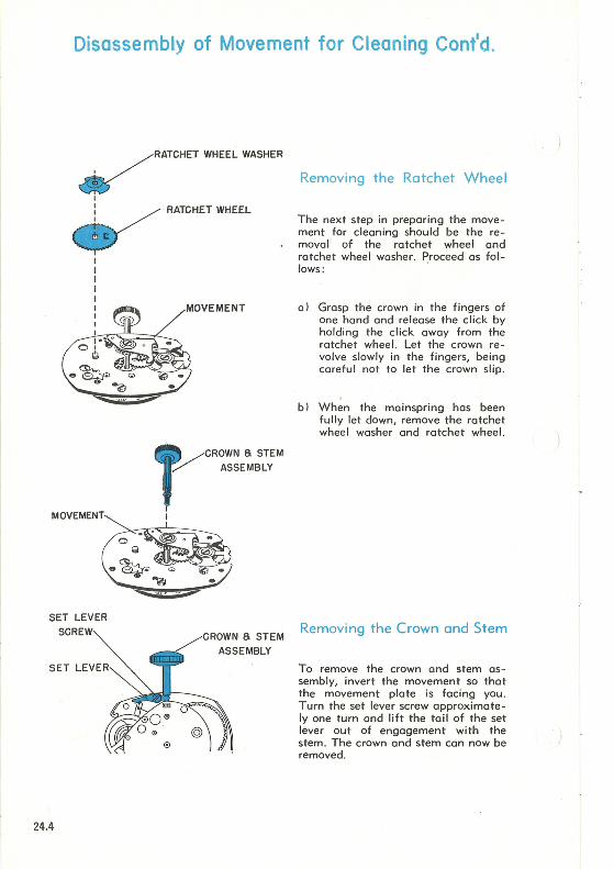
Removing the Ratchet Wheel
The next step in preparing the movement for cleaning should be the removal of the ratchet wheel and ratchet wheel washer. Proceed as fol-lows: .
a) Grasp the crown in the fingers of one hand and release the click by holding the click away from the ratchet wheel. Let the crown revolve slowly in the fingers, being careful not to let the crown slip.
b) When the mainspring has been fully let down, remove the ratchet wheel washer and ratchet wheel.
Removing the Crown and Stem
To remove the crown and stem assembly, invert the movement so 'that the movement plate is facing you . Turn the set lever screw approximately one turn and lift the tail of the set lever out of engagement with the stem. The crown and stem can now be removed .

Disassembly of Movement for Cleaning Cont'd.
BALANCE SCREW ASSEM.
BEARING
HAIRSPRING
r I i
____ j
E PIN
BALANCE ASSEM.
Removing the Balance
Two "V-conic" bearings are used as bearings for the balance staff on the TIMEX Model 24 movement. The bearing on the dial plate is driven into a screw so that fine endshake adjustment is possible.
Removal of the balance assembly should be carried out in the following manner:
a) Remove the hairspring wedge pin, being careful not to distort either the pin or the hairspring .
bl Rotate the balance slowly until the hairspring tail is free of the hairspring wedge pin bracket and the regu Ia tor .
c) Loosen the balance screw assembly (counterclockwise direction) using a suitable screwdriver, until the end of the balance staff is free of the "V -conic" bearing . During the loosening of the screw, only minimum downward pressure should be applied with the screwdriver, as excessive downward pressure could seriously damage the balance staff points.
d) Carefully remove the balance assembly.
24.5

Cleaning the Model 24 Movement
After removal of the balance, and the other parts mentioned in Pages 24.3 through 24.5, the movement is ready to be cleaned.
If a cleaning machine is used, place the movement in the basket with the dial plate down to insure proper drainage of the fluid from the mainspring barrel. It should be well swirled in the cleaning fluid after which two sets of rinsing fluid should be used. The final cleaning fluid must be absolutely clean . After cleaning, the movement should be thoroughly dried.
If a cleaning machine is not available, the same procedure should be followed manually, by re-inserting the stem, grasping the movement firmly around the stem and shaking it in the cleaning and rinsing fluids to insure that the fluid will pass through the entire mechanism.
The balance assembly should be cleaned separately in a small jar to prevent damage to the hairspring.
Only standard watch cleaning solutions should be used throughout .
Lubricating the Model 24 Movement
The· movement should be re-oiled in the normal manner using only high grade watch oils (oil used in factory assembly is Elgin M56bl. The mainspring is permanently lubricated with a solid coating which is not affected by normal cleaning solutions and should, therefore, not be ailed.
The upper pivot of the escape wheel can be oiled through the holes in the minute wheel.
The "V-conic" bearings should b~ oiled no less than 3;4 full before replacing the balance.
Oil both the top and bottom sides of the intermediate wind pinion and wind and set pinions.
24.6

DIAL PLATE
MOVEMENT PLATE
HAIRSPRING
SWEEP SECOND STAFF
Reassembly of the Model 24
CE SCREW
V-CONIC BEARING
SWEEP SECOND HAND
Replace the balance carefully into the movement by tilting the wheel and inserting first, the dial side pivot (hairspring side) then, the movement side pivot into the "V-conic bearing." Adjust the balance screw enough to hold the balance in place. By rotating the balance, insert the hairspring into the regulator slot and hairspring wedge pin bracket. Before repinning the hairspr ing, make certain the impulse pin is within the slot on the fork. Repin the hairspring making sure that the wedge pin is straight and true, as any distortion to the pin could interfere with the normal "breathing" of the hairspring. The endshoke is now finally adjusted using caution to apply only minimum downward pressure to the balance screw as excessive pressure could damage the points of the bo lance staff.
Inspect the hairspring to be certain that it is properly adjusted. As shown by the diagram, the hairspring should be in light permanent contact with the inside edge of the regulator slot. The hairspring should not leave the inside edge of the regulator slot during any port of its amplitude .
When replacing the dial assembly, set the hour and minute hands to 12:00 before bending the tabs on the dial holder to secure the dial. If the minute hand has been removed, replace it on the dial assembly together with the friction and cannon pinions ·before the dial assembly is put on the movement.
Replace the sweep second hand by driving it just below the end of the sweep second staff as shown in the diagram . Be certain the sweep hand is set below the chamfer on the top of the staff.
24.7