remedial action work plan for groundwater former timex...
TRANSCRIPT
REMEDIAL ACTION WORK PLAN FOR GROUNDWATER
FORMER TIMEX FACILITY LITTLE ROCK, ARKANSAS
Prepared for:
Timex Group USA Middlebury, Connecticut
Prepared by:
Weston Solutions, Inc. 45 Constitution Avenue, Suite 100 Concord, New Hampshire 03301
June 10, 2015
Work Order No. 13568.004.002
G:\PROJECTS\13568004\Planning Documents\Groundwater RAWP\Timex Groundwater RAWP 06-9-15.doc 10 June 2015
ii
TABLE OF CONTENTS
Section Page
1. INTRODUCTION.......................................................................................................... 1-1
2. SITE DESCRIPTION AND BACKGROUND ............................................................ 2-1
2.1 HYDROGEOLOGIC SETTING ......................................................................... 2-2
2.1.1 Geology ................................................................................................. 2-3 2.1.2 Hydrogeology ....................................................................................... 2-3
2.2 NATURE AND EXTENT OF GROUNDWATER CONTAMINATION .......... 2-5
2.3 SELECTED REMEDIAL ALTERNATIVE FOR GROUNDWATER .............. 2-6
3. BASIS OF DESIGN ....................................................................................................... 3-1
3.1 TREATMENT AREA ......................................................................................... 3-1
3.2 TREATMENT DEPTH ....................................................................................... 3-2
3.3 OXIDANT SELECTION ..................................................................................... 3-3
3.4 OXIDANT DOSAGE AND VOLUME .............................................................. 3-4
3.5 INJECTION METHOD ....................................................................................... 3-5
3.6 INJECTION SPACING ....................................................................................... 3-6
3.7 INJECTION SEQUENCING ............................................................................... 3-7
4. REMEDIAL ACTION IMPLEMENTATION ........................................................... 4-1
4.1 SITE ACCESS ..................................................................................................... 4-1
4.2 PERMITS ............................................................................................................. 4-2
4.3 SUBSURFACE UTILITIES ................................................................................ 4-2
4.4 SITE CONTROL ................................................................................................. 4-2
4.5 INJECTION POINT INSTALLATION .............................................................. 4-3
4.6 ISCO INJECTIONS ............................................................................................. 4-4
4.6.1 Permanganate Solution ......................................................................... 4-4 4.6.2 Permanganate Storage ........................................................................... 4-4 4.6.3 Utility Water ......................................................................................... 4-5 4.6.4 Mixing and Injection System ................................................................ 4-5 4.6.5 Spill Control Measures ......................................................................... 4-6 4.6.6 Neutralization Solution ......................................................................... 4-7
4.7 HEALTH AND SAFETY .................................................................................... 4-7
4.8 REPORTING ....................................................................................................... 4-8
G:\PROJECTS\13568004\Planning Documents\Groundwater RAWP\Timex Groundwater RAWP 06-9-15.doc 10 June 2015
iii
TABLE OF CONTENTS (Continued)
Section Page
5. SCHEDULE.................................................................................................................... 5-1
6. REFERENCES ............................................................................................................... 6-1
APPENDIX A MATERIAL SAFETY DATA SHEET
G:\PROJECTS\13568004\Planning Documents\Groundwater RAWP\Timex Groundwater RAWP 06-9-15.doc 10 June 2015
iv
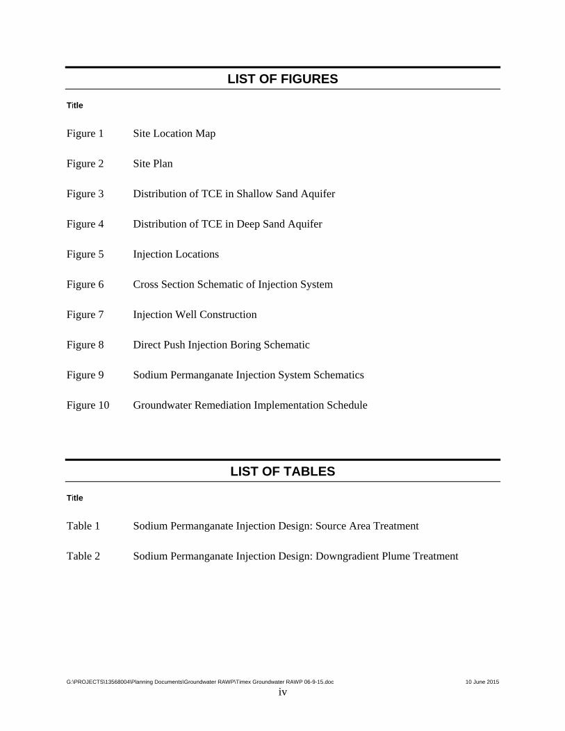
LIST OF FIGURES
Title
Figure 1 Site Location Map
Figure 2 Site Plan
Figure 3 Distribution of TCE in Shallow Sand Aquifer
Figure 4 Distribution of TCE in Deep Sand Aquifer
Figure 5 Injection Locations
Figure 6 Cross Section Schematic of Injection System
Figure 7 Injection Well Construction
Figure 8 Direct Push Injection Boring Schematic
Figure 9 Sodium Permanganate Injection System Schematics
Figure 10 Groundwater Remediation Implementation Schedule
LIST OF TABLES
Title
Table 1 Sodium Permanganate Injection Design: Source Area Treatment
Table 2 Sodium Permanganate Injection Design: Downgradient Plume Treatment
G:\PROJECTS\13568004\Planning Documents\Groundwater RAWP\Timex Groundwater RAWP 06-9-15.doc 10 June 2015
v
LIST OF ACRONYMS
1,1-DCE 1,1-Dichloroethene
1,1,1-TCA 1,1,1-Trichloroethane
ADEQ Arkansas Department of Environmental Quality
Airport Little Rock National Airport
CAO Consent Administrative Order
COPCs contaminants of potential concern
ft feet/foot
ft/day feet per day
ft/year feet per year
FTN FTN Associates, Ltd.
g/kg grams per kilogram
Groundater RAWP Remedial Action Work Plan for Groundwater
ISCO in situ chemical oxidation
MCL Maximum Contaminant Levels
mg/kg milligrams per kilogram
mg/L milligrams per liter
MNA monitored natural attenuation
PCE Tetrachloroethylene
psi pounds per square inch
PVC polyvinyl chloride
RAA Remedial Alternative Analysis
RADD Remedial Action Decision Document
RAL Remedial Action Level
TCE trichloroethylene
Timex Timex Group USA
UIC Underground Injection Control
VOC volatile organic compound
WESTON® Weston Solutions, Inc.
SECTION 1
INTRODUCTION
G:\PROJECTS\13568004\Planning Documents\Groundwater RAWP\Timex Groundwater RAWP 06-9-15.doc 10 June 2015
1-1
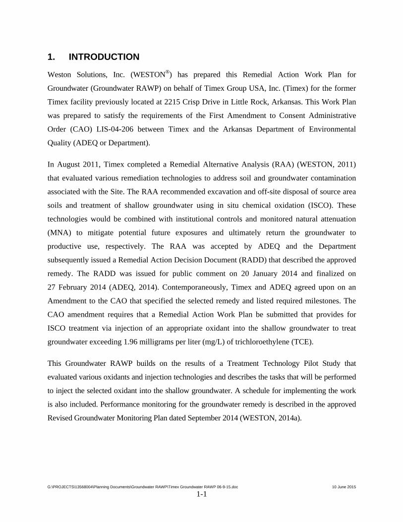
1. INTRODUCTION
Weston Solutions, Inc. (WESTON®) has prepared this Remedial Action Work Plan for
Groundwater (Groundwater RAWP) on behalf of Timex Group USA, Inc. (Timex) for the former
Timex facility previously located at 2215 Crisp Drive in Little Rock, Arkansas. This Work Plan
was prepared to satisfy the requirements of the First Amendment to Consent Administrative
Order (CAO) LIS-04-206 between Timex and the Arkansas Department of Environmental
Quality (ADEQ or Department).
In August 2011, Timex completed a Remedial Alternative Analysis (RAA) (WESTON, 2011)
that evaluated various remediation technologies to address soil and groundwater contamination
associated with the Site. The RAA recommended excavation and off-site disposal of source area
soils and treatment of shallow groundwater using in situ chemical oxidation (ISCO). These
technologies would be combined with institutional controls and monitored natural attenuation
(MNA) to mitigate potential future exposures and ultimately return the groundwater to
productive use, respectively. The RAA was accepted by ADEQ and the Department
subsequently issued a Remedial Action Decision Document (RADD) that described the approved
remedy. The RADD was issued for public comment on 20 January 2014 and finalized on
27 February 2014 (ADEQ, 2014). Contemporaneously, Timex and ADEQ agreed upon on an
Amendment to the CAO that specified the selected remedy and listed required milestones. The
CAO amendment requires that a Remedial Action Work Plan be submitted that provides for
ISCO treatment via injection of an appropriate oxidant into the shallow groundwater to treat
groundwater exceeding 1.96 milligrams per liter (mg/L) of trichloroethylene (TCE).
This Groundwater RAWP builds on the results of a Treatment Technology Pilot Study that
evaluated various oxidants and injection technologies and describes the tasks that will be performed
to inject the selected oxidant into the shallow groundwater. A schedule for implementing the work
is also included. Performance monitoring for the groundwater remedy is described in the approved
Revised Groundwater Monitoring Plan dated September 2014 (WESTON, 2014a).
SECTION 2
SITE DESCRIPTION AND BACKGROUND
G:\PROJECTS\13568004\Planning Documents\Groundwater RAWP\Timex Groundwater RAWP 06-9-15.doc 10 June 2015
2-1
2. SITE DESCRIPTION AND BACKGROUND
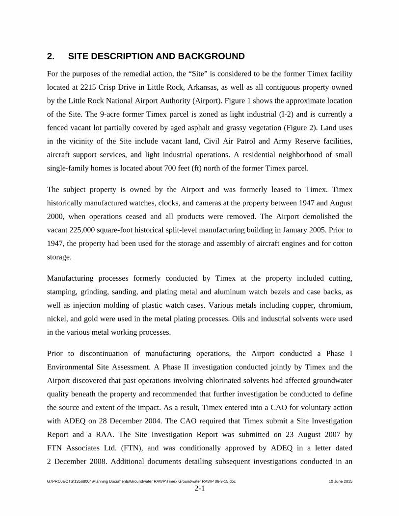
For the purposes of the remedial action, the “Site” is considered to be the former Timex facility
located at 2215 Crisp Drive in Little Rock, Arkansas, as well as all contiguous property owned
by the Little Rock National Airport Authority (Airport). Figure 1 shows the approximate location
of the Site. The 9-acre former Timex parcel is zoned as light industrial (I-2) and is currently a
fenced vacant lot partially covered by aged asphalt and grassy vegetation (Figure 2). Land uses
in the vicinity of the Site include vacant land, Civil Air Patrol and Army Reserve facilities,
aircraft support services, and light industrial operations. A residential neighborhood of small
single-family homes is located about 700 feet (ft) north of the former Timex parcel.
The subject property is owned by the Airport and was formerly leased to Timex. Timex
historically manufactured watches, clocks, and cameras at the property between 1947 and August
2000, when operations ceased and all products were removed. The Airport demolished the
vacant 225,000 square-foot historical split-level manufacturing building in January 2005. Prior to
1947, the property had been used for the storage and assembly of aircraft engines and for cotton
storage.
Manufacturing processes formerly conducted by Timex at the property included cutting,
stamping, grinding, sanding, and plating metal and aluminum watch bezels and case backs, as
well as injection molding of plastic watch cases. Various metals including copper, chromium,
nickel, and gold were used in the metal plating processes. Oils and industrial solvents were used
in the various metal working processes.
Prior to discontinuation of manufacturing operations, the Airport conducted a Phase I
Environmental Site Assessment. A Phase II investigation conducted jointly by Timex and the
Airport discovered that past operations involving chlorinated solvents had affected groundwater
quality beneath the property and recommended that further investigation be conducted to define
the source and extent of the impact. As a result, Timex entered into a CAO for voluntary action
with ADEQ on 28 December 2004. The CAO required that Timex submit a Site Investigation
Report and a RAA. The Site Investigation Report was submitted on 23 August 2007 by
FTN Associates Ltd. (FTN), and was conditionally approved by ADEQ in a letter dated
2 December 2008. Additional documents detailing subsequent investigations conducted in an
G:\PROJECTS\13568004\Planning Documents\Groundwater RAWP\Timex Groundwater RAWP 06-9-15.doc 10 June 2015
2-2
effort to respond to the ADEQ conditions presented in the approval letter have since been
submitted.
Following completion of the site investigation, a RAA was performed to evaluate remedial
options in accordance with the second requirement of the CAO. The RAA recommended a
remedial approach that consisted of a combination of active remediation, institutional controls,
and MNA. The active remediation would consist of excavation and off-site disposal of source
area soils and ISCO treatment of TCE in the shallow aquifer. The RAA describes the remedy
that formed the basis of the RADD that was issued on 27 February 2014.
Following issuance of the RADD and signing of the Amendment to the CAO, Timex
submitted the required planning documents including a Revised Groundwater Monitoring Plan
(WESTON, 2014a), Revised Treatment Technology Pilot Study Work Plan (WESTON, 2014b),
and a Revised Soil Remedial Action Work Plan (WESTON, 2014c). The baseline groundwater
monitoring round specified in the Revised Groundwater Monitoring Plan was conducted in
December 2014, and the results were reported in a Baseline Groundwater Sampling Report dated
February 2015 (WESTON, 2015a). Similarly, the ISCO pilot test was conducted in accordance
with the Revised Treatment Technology Pilot Study Work Plan, and the results were presented in
the Treatment Technology Pilot Study Report dated March 2015 (WESTON, 2015b). The results
of the baseline groundwater sampling and the ISCO pilot test were integral to the design of the
groundwater remedy.
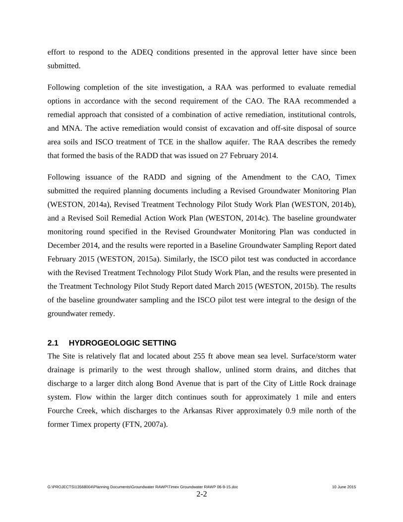
2.1 HYDROGEOLOGIC SETTING
The Site is relatively flat and located about 255 ft above mean sea level. Surface/storm water
drainage is primarily to the west through shallow, unlined storm drains, and ditches that
discharge to a larger ditch along Bond Avenue that is part of the City of Little Rock drainage
system. Flow within the larger ditch continues south for approximately 1 mile and enters
Fourche Creek, which discharges to the Arkansas River approximately 0.9 mile north of the
former Timex property (FTN, 2007a).
G:\PROJECTS\13568004\Planning Documents\Groundwater RAWP\Timex Groundwater RAWP 06-9-15.doc 10 June 2015
2-3
2.1.1 Geology
Regional geology is characterized by 75 to 100 ft of Quaternary alluvium overlying older, more
consolidated, Tertiary deposits of the Wilcox and Midway Groups. The Quaternary alluvium is a
relatively thick sequence of fluvial deposits from the Arkansas and Mississippi Rivers and their
tributaries that is composed primarily of sand, silt, and clay. These deposits make up the Surficial
Alluvial Aquifer System.
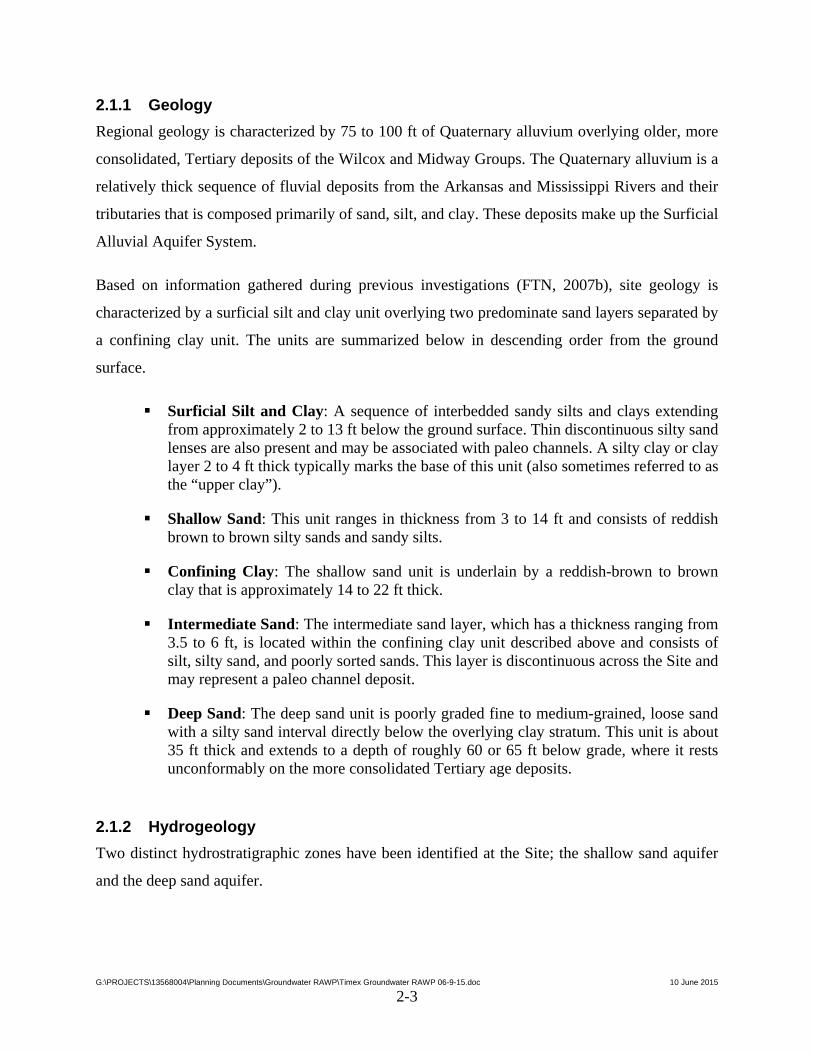
Based on information gathered during previous investigations (FTN, 2007b), site geology is
characterized by a surficial silt and clay unit overlying two predominate sand layers separated by
a confining clay unit. The units are summarized below in descending order from the ground
surface.
Surficial Silt and Clay: A sequence of interbedded sandy silts and clays extending from approximately 2 to 13 ft below the ground surface. Thin discontinuous silty sand lenses are also present and may be associated with paleo channels. A silty clay or clay layer 2 to 4 ft thick typically marks the base of this unit (also sometimes referred to as the “upper clay”).
Shallow Sand: This unit ranges in thickness from 3 to 14 ft and consists of reddish brown to brown silty sands and sandy silts.
Confining Clay: The shallow sand unit is underlain by a reddish-brown to brown clay that is approximately 14 to 22 ft thick.
Intermediate Sand: The intermediate sand layer, which has a thickness ranging from 3.5 to 6 ft, is located within the confining clay unit described above and consists of silt, silty sand, and poorly sorted sands. This layer is discontinuous across the Site and may represent a paleo channel deposit.
Deep Sand: The deep sand unit is poorly graded fine to medium-grained, loose sand with a silty sand interval directly below the overlying clay stratum. This unit is about 35 ft thick and extends to a depth of roughly 60 or 65 ft below grade, where it rests unconformably on the more consolidated Tertiary age deposits.
2.1.2 Hydrogeology
Two distinct hydrostratigraphic zones have been identified at the Site; the shallow sand aquifer
and the deep sand aquifer.
G:\PROJECTS\13568004\Planning Documents\Groundwater RAWP\Timex Groundwater RAWP 06-9-15.doc 10 June 2015
2-4
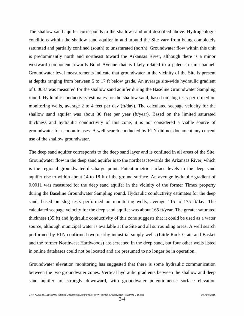
The shallow sand aquifer corresponds to the shallow sand unit described above. Hydrogeologic
conditions within the shallow sand aquifer in and around the Site vary from being completely
saturated and partially confined (south) to unsaturated (north). Groundwater flow within this unit
is predominantly north and northeast toward the Arkansas River, although there is a minor
westward component towards Bond Avenue that is likely related to a paleo stream channel.
Groundwater level measurements indicate that groundwater in the vicinity of the Site is present
at depths ranging from between 5 to 17 ft below grade. An average site-wide hydraulic gradient
of 0.0087 was measured for the shallow sand aquifer during the Baseline Groundwater Sampling
round. Hydraulic conductivity estimates for the shallow sand, based on slug tests performed on
monitoring wells, average 2 to 4 feet per day (ft/day). The calculated seepage velocity for the
shallow sand aquifer was about 30 feet per year (ft/year). Based on the limited saturated
thickness and hydraulic conductivity of this zone, it is not considered a viable source of
groundwater for economic uses. A well search conducted by FTN did not document any current
use of the shallow groundwater.
The deep sand aquifer corresponds to the deep sand layer and is confined in all areas of the Site.
Groundwater flow in the deep sand aquifer is to the northeast towards the Arkansas River, which
is the regional groundwater discharge point. Potentiometric surface levels in the deep sand
aquifer rise to within about 14 to 18 ft of the ground surface. An average hydraulic gradient of
0.0011 was measured for the deep sand aquifer in the vicinity of the former Timex property
during the Baseline Groundwater Sampling round. Hydraulic conductivity estimates for the deep
sand, based on slug tests performed on monitoring wells, average 115 to 175 ft/day. The
calculated seepage velocity for the deep sand aquifer was about 165 ft/year. The greater saturated
thickness (35 ft) and hydraulic conductivity of this zone suggests that it could be used as a water
source, although municipal water is available at the Site and all surrounding areas. A well search
performed by FTN confirmed two nearby industrial supply wells (Little Rock Crate and Basket
and the former Northwest Hardwoods) are screened in the deep sand, but four other wells listed
in online databases could not be located and are presumed to no longer be in operation.
Groundwater elevation monitoring has suggested that there is some hydraulic communication
between the two groundwater zones. Vertical hydraulic gradients between the shallow and deep
sand aquifer are strongly downward, with groundwater potentiometric surface elevation
G:\PROJECTS\13568004\Planning Documents\Groundwater RAWP\Timex Groundwater RAWP 06-9-15.doc 10 June 2015
2-5
differences between the two units ranging from about 6 to 9 ft in the vicinity of the Site. The
vertical gradient remains downward northeast (downgradient) of the former Timex property; but
the differences in potentiometric elevations between the two aquifers decreases as you move
away from the Site (FTN, 2007b).
2.2 NATURE AND EXTENT OF GROUNDWATER CONTAMINATION
Investigation of environmental conditions has been ongoing at the Site for the last 10 years.
Hundreds of samples of various environmental media (including soil, groundwater, surface
water, sediment, and indoor air) have been collected and analyzed for potential site
contaminants. The investigations have shown that some industrial solvents and their breakdown
products are present in the environment as a result of manufacturing operations at the facility.
Some of these compounds have migrated downgradient and extend off the former Timex
property to the west, north, and east. Two suspected source areas were identified: a former
plating room/effluent treatment plant area within the footprint of the former manufacturing
building, and a storm drain located near the northwest corner of the former building. Removal of
contaminated soils exceeding the RADD cleanup goal of 0.78 milligrams per kilogram (mg/kg)
TCE from the two source areas was completed in May 2015, thereby addressing the source of the
groundwater contamination.
The RADD identified the chemicals of potential concern (COPCs) for groundwater at the Site as:
1,1,1-Trichloroethane (1,1,1-TCA) 1,1,2-Trichloroethane 1,1-Dichloroethane 1,2-Dichloroethane 1,1-Dichloroethene (1,1-DCE) Cis-1,2-dichloroethene 1,4-Dioxane Freon 113 Tetrachloroethylene (PCE) TCE Vinyl Chloride Manganese
The COPCs for groundwater were identified based largely on exceedances of the United States
Environmental Protection Agency Maximum Contaminant Levels (MCLs). For those compounds
G:\PROJECTS\13568004\Planning Documents\Groundwater RAWP\Timex Groundwater RAWP 06-9-15.doc 10 June 2015
2-6
that did not have MCLs, the Regional Screening Levels for Tapwater were used. Manganese was
not specifically named as a chemical of concern in the Site Investigation Report (FTN, 2007b)
because it was not released into the environment as a result of former manufacturing operations,
but rather is a naturally-occurring compound that can be mobilized by biodegradation of the
chlorinated solvents that were a result of historical releases at the Site. However, ADEQ has
required that manganese be included as a COPC for groundwater and that concentrations in
groundwater be evaluated during the MNA portion of the remedy.
The most pervasive COPC for groundwater is the industrial solvent TCE and its breakdown
products, including 1,1-DCE. Concentrations of TCE as high as 32 mg/L have been historically
observed in groundwater beneath the Site, although more recent data show that the maximum
TCE concentration has decreased to 12 mg/L as of December 2014 (WESTON, 2015a).
Remediation of impacted soils associated with the western end of the storm drain on the north
side of the former building identified several pipes entering the catch basins near MW-18S from
within the footprint of the former building and these are believed to be the release point for the
TCE contamination into the storm drain. The pipes, catch basins, and impacted portion of the
storm drain were removed in April-May 2015. Figures 3 and 4 show the estimated extent of
volatile organic compound (VOC) contamination in the shallow and deep aquifers, respectively,
based on the results of the baseline groundwater sampling round completed in December 2014.
A small area of 1,1,1-TCA contamination formerly existed in shallow groundwater in the
vicinity of monitoring well MW-10S that was believed to be related to the former plating
room/effluent treatment plant located in the south central portion of the former manufacturing
building. However, since removal of the former Timex building in 2005, 1,1,1-TCA
concentrations in groundwater have decreased and no longer exceed the cleanup criteria
(WESTON, 2015a).
2.3 SELECTED REMEDIAL ALTERNATIVE FOR GROUNDWATER
As mentioned above, Timex completed a comprehensive RAA that screened 24 different
remedial technologies, of which 10 were determined to be potentially applicable to the Site. The
ten applicable technologies were used to develop four remedial action alternatives, which were
G:\PROJECTS\13568004\Planning Documents\Groundwater RAWP\Timex Groundwater RAWP 06-9-15.doc 10 June 2015
2-7
then evaluated against nine performance criteria. Based on this evaluation, ADEQ selected the
approved remedy for the Site that is described in the RADD.
The approved remedy includes the application of institutional controls that will limit use of
properties that lie within the area of the shallow groundwater plume to industrial activities (as
defined therein) and prevent the use of groundwater on-site and off-site within the area affected
by the deep groundwater contamination. Deed restrictions already have been obtained from the
Airport to limit site use to industrial activities and to prevent the use of deep groundwater
on-site. Similarly, an ordinance has been obtained from the City of Little Rock covering the
United States Army Reserve Center adjacent to the Site and limiting its use to industrial
activities and prohibiting the use of groundwater. Deed restrictions also have been obtained
restricting groundwater use for many off-site properties within the area affected by the deep
groundwater contamination, and work is ongoing to obtain either deed restrictions or an
ordinance regarding the remaining properties.
Active groundwater remediation consisting of ISCO treatment of shallow groundwater exceeding
the Remedial Action Level (RAL) of 1.96 mg/L of TCE will be performed to mitigate potential
vapor intrusion risk to on-site future industrial workers.

SECTION 3
BASIS OF DESIGN
G:\PROJECTS\13568004\Planning Documents\Groundwater RAWP\Timex Groundwater RAWP 06-9-15.doc 10 June 2015
3-1
3. BASIS OF DESIGN
The groundwater remedial action will consist of ISCO treatment of shallow groundwater that
exceeds the RAL of 1.96 mg/L of TCE, and MNA for the remaining areas. The MNA monitoring
program was provided in the Revised Groundwater Monitoring Plan (WESTON, 2014a) and
approved by ADEQ. This section provides the engineering design basis for the ISCO treatment.
3.1 TREATMENT AREA
A comprehensive groundwater sampling round was conducted in December 2014 to provide a
baseline condition for design of the ISCO treatment and also for comparison during post-
treatment performance monitoring for the ISCO and MNA remedies (WESTON, 2015a). The
baseline groundwater sampling included all existing monitoring wells at the Site. The TCE
results were plotted on a site map and isoconcentration contours were developed to estimate the
extent of shallow groundwater exceeding the RAL of 1.96 mg/L (see Figure 3). The extent of the
shallow groundwater requiring treatment with ISCO is shown on Figure 5 and corresponds with
the 2,000 micrograms per liter isoconcentration contour shown on Figure 3.
The treatment area has been divided into two zones for the purposes of the ISCO treatment;
source area and downgradient plume. The source area relates to the zone around the former
storm drain where it is believed that TCE may have been released. During removal of the storm
drain, confirmation samples from the bottom of the excavation showed TCE concentrations as
high as 360 mg/kg in the surficial silt and clay layer. These TCE concentrations are related to the
release of TCE to the storm drain (2 to 3 ft below grade) and migration of the TCE downward
through the surficial silt and clay layer to the shallow sand aquifer. The unsaturated soil was
removed during the soil remediation but residual contamination remains in the saturated soil
above the shallow sand aquifer. This residual contamination could act as a continuing source to
groundwater contamination in the underlying shallow sand aquifer. Therefore, ISCO treatment in
the source area will include this layer.
The downgradient plume includes the shallow sand aquifer downgradient of the source area
where TCE exceeds the cleanup goal of 1.96 mg/L. In that zone, TCE is restricted largely to the
shallow sand aquifer itself with only minor penetration of the TCE into the overlying silt and
G:\PROJECTS\13568004\Planning Documents\Groundwater RAWP\Timex Groundwater RAWP 06-9-15.doc 10 June 2015
3-2
clay surficial layer and the underlying confining clay layer via diffusion. Under those conditions,
ISCO treatment of the shallow sand aquifer will be sufficient to treat all of the TCE because the
high permanganate dosage will drive the permanganate into the underlying and overlying
material via diffusion similar to the TCE.
3.2 TREATMENT DEPTH
The RADD requires that the ISCO treatment be conducted on the shallow groundwater aquifer.
Extensive mapping of the various groundwater zones was performed by FTN between 2004 and
2008 (FTN, 2007a,b). Geologic cross-sections were developed based on over 130 soil borings
and 60 monitoring wells, depicting the depth and thickness of the shallow sand aquifer. Those
cross-sections were used to design the depth of the ISCO injection points. The shallow sand is
approximately 7 to 8 ft thick in the vicinity of the former Timex property and is encountered at a
depth of approximately 11 to 12 ft below grade. The shallow sand aquifer thins to the north and
is only 3 to 4 ft thick at the northern end of the treatment area near MW-29S, where it is
encountered at a depth of about 12 to 13 ft.
Because there is some variation in the depth and thickness of the shallow sand across the
treatment area, a conservative thickness of 10 ft was selected for the ISCO treatment. The depth
of the ISCO treatment will vary based on location (see Figure 5). Treatment points east of the
alley between the former Timex property and the Civil Air Patrol will be approximately 2 ft
shallower than those to the west of the alley. This is to take into account a change in grade
between the two areas that is related to a short concrete retaining wall at the edge of the parking
lot, west of the alley. The injection points east of the parking lot will target the 8- to 18-ft
interval while the injection points west and north of the parking lot will target the 10- to 20-ft
interval. Figure 6 is a schematic cross-section of the injection system showing the relative depths
of the injection points in relation to the shallow sand aquifer.
For the ISCO injection wells that will be used to treat the downgradient portion of the plume, a
10-foot (ft) screened section will be used to straddle the shallow sand aquifer. The injected
oxidant will preferentially flow into the sandy material providing maximum treatment of the
target zone via convection but still providing some treatment to the overlying and underlying
finer-grained material via diffusion.
G:\PROJECTS\13568004\Planning Documents\Groundwater RAWP\Timex Groundwater RAWP 06-9-15.doc 10 June 2015
3-3
For the direct-push ISCO borings used to treat the source area, oxidant will be injected into three
different 2-ft intervals. This will facilitate convective flow of oxidant into the overlying and
underlying finer-grained material to provide greater treatment for those soils in the source area
where higher TCE concentrations are present. The injection volumes will be varied such that the
middle zone gets a larger percentage of the total amount for each injection point to offset the
higher permeability in that zone.
3.3 OXIDANT SELECTION
The oxidant selected for this Site is sodium permanganate. Sodium permanganate has the
greatest persistence of all of the common oxidants, often persisting in the subsurface for 1 to
2 years after injection. This is a great advantage because it allows the oxidant more time to
diffuse into finer-grained material and react with the contaminants, which provides more
complete treatment with less chance for rebound. Sodium permanganate is preferred over
potassium permanganate because it is over 10 times more soluble in water, which enables a
stronger solution to be used and minimizes the volume of fluid injected. Sodium permanganate is
very effective at treating chlorinated ethenes such as PCE, TCE, and their breakdown products.
The results of the laboratory treatability test (WESTON, 2015b) showed that TCE was
completely destroyed by the sodium permanganate, even at the lowest dose tested.
A 20% sodium permanganate solution will be used for the injections in the source area and a
10% solution will be used in the downgradient plume. Sodium permanganate is typically
delivered as a 40% solution (which is close to its maximum solubility) to reduce shipping costs.
However, 40% sodium permanganate is slightly viscous and more problematic to handle so it is
routinely diluted on-site with water to create less dilute solutions for injection. Aside from being
easier to handle and less of a safety concern, the density of 20% sodium permanganate is nearly
identical to that of TCE. That means that the 20% solution will tend to follow the same pathways
as the TCE when it was released. This is why 20% is proposed for the source area, where it is
believed the TCE was released. A 10% sodium permanganate solution will be used for the
downgradient plume because it will result in a larger injection volume and mix more fully with
the groundwater, thereby providing better distribution of permanganate between the wider-
spaced injection points in this area.

G:\PROJECTS\13568004\Planning Documents\Groundwater RAWP\Timex Groundwater RAWP 06-9-15.doc 10 June 2015
3-4
3.4 OXIDANT DOSAGE AND VOLUME
The results of the treatability test (WESTON, 2015b) showed that the TCE was fully destroyed
by the lowest dose [2.0 grams per kilogram (g/kg)] evaluated. The treatability test was conducted
using soil and groundwater from the most highly-contaminated area of the Site (vicinity of MW-
18S). This area was confirmed to be the primary release point for TCE during the soil
remediation when a pipe was discovered leading from the former Timex building into the catch
basin located just east of MW-18S. Further, MW-18S has consistently had the highest observed
TCE concentrations in the shallow sand aquifer, up to 17.3 mg/L. Because the treatability test
was conducted using the worst-case soil and groundwater conditions, and the lowest dose of
sodium permanganate tested (2.0 g/kg) fully destroyed the TCE, that dose represents the upper
bound that would be required to achieve the cleanup goal. It is likely that a much lower dose
would be required in downgradient areas where the TCE concentrations are significantly less. To
account for this conservancy, the ISCO injections will be performed as a series of injections
based on a percentage of the upper bound dose.
The dosage calculations are shown in Tables 1 and 2 for the source area and downgradient
plume, respectively. The calculations use the upper bound of 2.0 g/kg as a conservative
assumption for the source area treatment due to the higher TCE concentrations there and a more
reasonable value of 1.0 g/kg for the downgradient plume. It should be noted that both sets of
dosage calculations use a treatment thickness of 10 ft, which is another conservative assumption
given the mapped thickness of the shallow sand aquifer (3 to 8 ft thick) as discussed above. This
is especially true for the downgradient plume area where the advective flow zone is estimated to
be only 3 to 4 ft, and further justifies using the lower dose rate of 1.0 g/kg. Based on the
calculations in Tables 1 and 2, the total estimated volume of sodium permanganate solution
required for maximum treatment would be approximately 420 gallons of 20% solution for each
source area direct push injection boring and approximately 2,580 gallons of 10% solution for
each downgradient injection well. The volume is greater for the downgradient points because a
more dilute solution is being applied and the injection points are spaced further apart and
therefore each point must treat a larger area of the aquifer.
Because the injection volume calculations are based on several conservative assumptions,
including treatment zone thickness, TCE concentration, and unit dose rate; it is most likely that a
G:\PROJECTS\13568004\Planning Documents\Groundwater RAWP\Timex Groundwater RAWP 06-9-15.doc 10 June 2015
3-5
smaller amount of sodium permanganate will be required to achieve the cleanup goals. To
account for this unknown, the ISCO treatment will be performed as a series of smaller injections
rather than a single injection of the full amount. This will allow Timex to customize the amount
of permanganate needed in each area; thereby minimizing the amount of residual permanganate
remaining after treatment is complete. Note that unused permanganate will auto-degrade over
time, but it is a slow process often requiring more than 3 years and adds more manganese to the
aquifer than is necessary.
The initial injection would be 50% of the total estimated volume, so approximately 210 gallons
of 20% solution per source area injection boring and 1,290 gallons of 10% solution per
downgradient injection well. Post-injection monitoring of permanganate concentrations in
groundwater per the Revised Groundwater Monitoring Plan will be used to determine where and
when the second injection would be performed. The volume of permanganate used for the
second injection would be adjusted based on the results of the monitoring, but it is anticipated
that it would be approximately 25% of the total estimated volume. The third injection would be
the final 25%. WESTON’s experience at similar sites is that the area of each subsequent
injection round is smaller than the previous one. The initial 50% volume is typically sufficient to
fully attain the cleanup goal around the edges of the plume, leaving only the center of the plume
requiring additional treatment. Similarly, after the second injection, more of the plume attains the
cleanup goal leaving only a small source area requiring final treatment with a third injection.
Occasionally, a fourth or even fifth injection round is needed to treat recalcitrant locations,
typically right at the release point. But because there is no way to conclusively determine where
those areas are before beginning the treatment, this is the most efficient way to achieve the
cleanup goal without needlessly overdosing the aquifer.
3.5 INJECTION METHOD
A field pilot test was conducted to evaluate three different ISCO injection methods: direct push
drilling equipment, small-diameter injection wells, and standard 2-inch-diameter monitoring
wells (WESTON, 2015b). In general, all three injection methods performed well and were able
to attain favorable injection rates (approximately 7 gallons per minute) with only moderate
backpressure [<75 pounds per square inch (psi)]. The direct push method was found to be more

G:\PROJECTS\13568004\Planning Documents\Groundwater RAWP\Timex Groundwater RAWP 06-9-15.doc 10 June 2015
3-6
capable of injecting oxidant into lower-permeability layers than either the injection wells or the
monitoring wells due to the shorter screen length. As a result, the direct push method provides
more control with regard to injecting the oxidant into specific zones and therefore can provide
better vertical distribution of the oxidant. This is particularly useful for source area treatment
where TCE contamination is more likely to have penetrated into the overlying and underlying
finer-grained material.
The use of longer-screen injection wells is applicable for downgradient applications at this Site
where the TCE is largely confined to the shallow sand aquifer, with only minimal diffusion into
the overlying and underlying finer-grained material. The injection wells and monitoring wells
performed similarly, with no real advantage for one over the other. Both hydraulic and thermal
responses to the test injections were consistently observed at distances of 15 to 20 ft in the more
permeable zones. These observations were based on injection of approximately 70 gallons of
water, so injection of the larger volumes associated with the full-scale remediation would result
in a proportionally larger radius of influence.
A combined approach to oxidant injection will be used at this Site. Direct push injection borings
with three 2-ft-long injection intervals per boring would be used to treat the source area to
provide the best horizontal and vertical distribution of the oxidant. Small-diameter injection
wells (10-ft screen) will be used to create injection barriers to treat downgradient portions of the
plume. These injection wells will be used to apply a larger volume of oxidant into the shallow
sand aquifer and allow the natural groundwater flow to distribute the oxidant downgradient. The
injection wells more easily facilitate future injections than the direct push borings and also
provide additional monitoring points to assess the distribution of oxidant within the aquifer and
VOC monitoring to verify the effectiveness.
3.6 INJECTION SPACING
The direct push injection borings will be installed on a 20-ft grid within the source area. The grid
lines will be off-set by 10 ft to provide better distribution of the oxidant. Subsequent injection
borings will be off-set from the initial borings by 10 ft to provide an even finer spacing in areas
requiring further treatment. The results of the pilot study (WESTON, 2015b) showed excellent
hydraulic and thermal tracer response at a distance of 20 ft based on an injection volume of
G:\PROJECTS\13568004\Planning Documents\Groundwater RAWP\Timex Groundwater RAWP 06-9-15.doc 10 June 2015
3-7
approximately 70 gallons depth interval per location. This compares favorably with the planned
injection volume of 210 gallons per point for the first injection. The fact that subsequent
injections will be off-set from the initial injection will provide a 10-ft effective spacing. Figure 5
shows the layout of the initial injection grid; subsequent grids will be off-set from the one shown
by 10 ft.
For the downgradient plume, existing infrastructure prevents injection on a finely-spaced grid as
is proposed for the source area. The Civil Air Patrol building and Crisp Drive occupy a
significant portion of the downgradient plume. As a result, the approach is to use the small
diameter injection wells to inject a large volume of oxidant and rely on convective groundwater
flow to distribute the oxidant downgradient, beneath the surface infrastructure. The injection
wells will be installed as a series of treatment barriers perpendicular to the main axis of the
plume (see Figure 5). The spacing of points within the barriers is 30 ft, based on the results of the
pilot study that show good hydraulic and thermal response at a minimum of 20 ft for an injection
volume of 70 gallons. The planned initial injection volume for the barrier wells is more than
18 times greater at 1,290 gallons. The injection barriers will be spaced at 60-ft intervals, based
on a conservative seepage velocity of 30 ft per year and an assumed oxidant persistence of
2 years. The 30 ft per year seepage velocity was calculated using the measured hydraulic
gradient (0.0087) and the lowest measured hydraulic conductivity of 2 ft/day. It is likely that the
actual hydraulic conductivity for the shallow sand aquifer in the downgradient area is closer to
the higher end of the range because the thickness of the aquifer is known to be less, yet the
hydraulic gradient does not change. Therefore, the seepage velocity is expected to be at least
60 ft/yr. Oxidant monitoring in accordance with the Revised Groundwater Monitoring Plan will
be used to verify the performance of the injection barriers. Additional oxidant injections or
injection points will be added, if necessary, to achieve the cleanup goal of 1.96 mg/L TCE.
3.7 INJECTION SEQUENCING
The sequence of ISCO injections must be performed properly to avoid pushing contaminated
groundwater out of the treatment zone. Injections in the source area via the direct-push borings
will be performed around the perimeter of the treatment area and working inward. This will
create a barrier of oxidant around the edges of the treatment zone and ensure that contaminated
G:\PROJECTS\13568004\Planning Documents\Groundwater RAWP\Timex Groundwater RAWP 06-9-15.doc 10 June 2015
3-8
groundwater above the RAL cannot be pushed outside the treatment zone without coming into
contact with the oxidant.
For the downgradient plume, the small diameter injection wells will all be installed before
injections in this area are initiated. As with the source area, injections will be conducted into the
perimeter injection wells first, and then working inward. The injections will be performed
starting downgradient and moving southward towards the source area.
SECTION 4
REMEDIAL ACTION IMPLEMENTATION
G:\PROJECTS\13568004\Planning Documents\Groundwater RAWP\Timex Groundwater RAWP 06-9-15.doc 10 June 2015
4-1
4. REMEDIAL ACTION IMPLEMENTATION
The remedy selected for groundwater at the Timex Site is the injection of a chemical oxidant in
shallow groundwater to attain the RAL of 1.96 mg/L TCE. As detailed in the Basis of Design,
the oxidant selected for this Site is sodium permanganate. The estimated maximum dosage
required to treat the groundwater is roughly 167,900 pounds of sodium permanganate. Because
the maximum dosage was calculated using a series of conservative assumptions, the actual
amount of sodium permanganate that will be injected is likely much less than that. To account
for this, the treatment will be conducted in a phased approach consisting of multiple injections.
The initial injection will be 50% of the estimated maximum dose (23,750 gallons of 20% sodium
permanganate in the source area injection borings and approximately 47,700 gallons of 10%
solution in the downgradient plume injection wells). Permanganate and VOC monitoring will
then be conducted in accordance with the approved Revised Groundwater Monitoring Plan
(WESTON, 2014a) and that data will be used to determine the scope and timing of subsequent
injections. It is believed that three injections will be required to achieve the RAL in all areas of
the Site, but it could be fewer or more than that.
The sodium permanganate will be injected into the subsurface using a combination of small
diameter injection wells (in downgradient areas) and direct push injection borings (in the source
area) as show on Figure 5. A total of 150 injection points are planned. The sodium permanganate
will be delivered as a 40% solution and diluted on-site to 20% and 10% solutions using potable
water from a fire hydrant. A trailer-mounted injection pumping system will be used to inject the
permanganate solutions into each injection point. For the initial injection event, approximately
210 gallons of 20% sodium permanganate will be injected into each direct push injection boring
and 1,290 gallons of 10% solution will be injected into each small diameter injection well. The
amount of sodium permanganate needed for subsequent injections and the locations requiring
injections will be determined based on the permanganate and VOC monitoring results.
4.1 SITE ACCESS
All areas where ISCO injections will be performed are located on property owned by the Airport.
Timex has a signed Access Agreement in place with the Airport that includes performance of

G:\PROJECTS\13568004\Planning Documents\Groundwater RAWP\Timex Groundwater RAWP 06-9-15.doc 10 June 2015
4-2
this groundwater remediation work. Timex will coordinate closely with the Airport during all
phases of the groundwater remediation.
4.2 PERMITS
The ISCO injection points are considered Class V injection wells and authorization is required
under the Underground Injection Control (UIC) Permit by Rule to perform the injections.
Authorization under the UIC program was obtained from ADEQ for the pilot study injection of
potable water. Timex will submit a request to modify that authorization to include the full-scale
injections of sodium permanganate once this Groundwater RAWP is approved.
Timex will also notify the City of Little Rock and coordinate with the local fire and police
precincts with regard to the type and amount of chemical that will be stored on-site during the
injections.
4.3 SUBSURFACE UTILITIES
Prior to beginning installation of the small-diameter injection wells or direct-push injection
borings, the planned drilling locations will be marked in the field and Arkansas One Call will be
contacted to mark subsurface utilities. The Airport, Central Arkansas Water, and City of Little
Rock will also be directly contacted and asked to mark out any subsurface utilities that they are
aware of that might not be covered by Arkansas One Call. Further, locations of previously
unknown utilities discovered during the soil remediation work (water and gas lines) will also be
marked in the field.
4.4 SITE CONTROL
The former Timex property is fully contained by a 6-ft security fence. Similarly, the area to the
north of Crisp Drive is fenced. However, the area west of the former Timex property and south
of Crisp Drive, encompassing the Civil Air Patrol building and associated parking lot, are not
fenced. Temporary construction fencing will be employed during injection events to extend the
existing permanent fence across the alley west of the former Timex property and around the
work area to restrict off-hours access.
G:\PROJECTS\13568004\Planning Documents\Groundwater RAWP\Timex Groundwater RAWP 06-9-15.doc 10 June 2015
4-3
It is anticipated that the alley that extends southward from Crisp Drive along the western
boundary of the former Timex property will be closed to public traffic during injections in that
area. Because this is a dead-end alley that is controlled by the Airport and receives almost no
daily traffic, this temporary closure will not adversely impact any local businesses or residents.
The alley was closed for several weeks during the soil remediation without any known impact.
4.5 INJECTION POINT INSTALLATION
The sodium permanganate will be injected into the subsurface using a combination of small
diameter injection wells (in downgradient areas) and direct push injection borings (in the source
area) as shown on Figure 5.
The small diameter injection wells will be constructed as shown on Figure 7 and will be installed
using direct push methods. A total of 37 small diameter injection wells will be installed
(Figure 5). The 2.5-inch-diameter direct-push casing will be pushed to the design depth based on
location (between 18 and 20 ft below grade). A removable steel plug will be deployed on the
drilling rods to keep the casing free of soil as the casing is advanced. Each well point will consist
of 10 ft of 1-inch-diameter, 10-slot polyvinyl chloride (PVC) screen and an appropriate length of
1-inch-diameter riser pipe. The well points will be installed by inserting the 1-inch-diameter
PVC well casing into the direct-push casing and retracting the casing. Filter sand will be added
to a depth of 2 ft above the top of the screen as the casing is removed. A 3-ft-thick layer of fine-
grained bentonite pellets (‘crumble’) will be placed in the borehole annulus above the sand pack
and hydrated in place with potable water. The remainder of the borehole annulus will be filled
with medium bentonite chips. This will help to reduce the potential for daylighting of the
injection water. An appropriate size road box will be installed at the surface to protect the
injection wells. Figure 7 shows a schematic of the small diameter injection wells.
The direct push injection borings will be performed using a 2-ft-long injection tip attached to the
direct-push drilling rods. The injection tip will be advanced to the target depth. Once the target
depth has been reached, a threaded fitting will be attached to the top of the casing such that the
water injection system (pump, flow meter, pressure gauge, flow control valve, etc.) can be
connected. The 20% sodium permanganate solution will then be pumped into the drilling rods
and the rate and back pressure monitored and recorded until the desired volume of oxidant has
G:\PROJECTS\13568004\Planning Documents\Groundwater RAWP\Timex Groundwater RAWP 06-9-15.doc 10 June 2015
4-4
been delivered. The injection system will be disconnected and the injection tip will then be
pushed to the next injection interval. The injection system will be reconnected and the second
interval will be treated. This process will be repeated for the third treatment interval. Figure 8
shows a schematic of the direct push injection borings. Approximately 113 direct push injection
borings will be installed.
4.6 ISCO INJECTIONS
A single location will be used for the storage, mixing, and distribution of the sodium
permanganate for all injection points (direct push injection borings and small diameter injection
wells). The system is described below.
4.6.1 Permanganate Solution
Sodium permanganate solution (40% by weight) will be delivered to the Site in bulk shipments
of 5,000 to 10,000 gallons via tanker truck. Approximately 18,400 gallons of 40% sodium
permanganate will be needed to complete the initial injection round at this Site. In order to
provide a solution with the proper density and viscosity for injection, the permanganate will be
diluted with water to either a 10% or 20% solution prior to injection into the subsurface.
4.6.2 Permanganate Storage
The 40% sodium permanganate solution will be stored in two 8,000-gallon temporary storage
tanks located in the paved parking area at the north end of the former Timex property as shown
on Figure 5. Spill containment consisting of 10-mil polyethylene sheeting with bermed sides, or
equivalent pre-manufactured spill containment devices will be used around both tanks and an
adjacent mixing area where smaller 300-gallon totes will be filled with either 10% or 20%
sodium permanganate solution. The bermed sides will be constructed by wrapping the edges of
the sheeting around and under sandbags or similar to create a berm of at least 1 ft in height. The
containment area will be constructed with a volume at least 10% greater than the volume of the
stored permanganate solution.
G:\PROJECTS\13568004\Planning Documents\Groundwater RAWP\Timex Groundwater RAWP 06-9-15.doc 10 June 2015
4-5
4.6.3 Utility Water
Potable water will be obtained from a fire hydrant located on-site near the permanganate storage
and mixing area. This is the same hydrant that was used to supply water during the Treatment
Technology Pilot Study (WESTON, 2015a). This water will be used for dilution of the
permanganate prior to injection and for equipment decontamination purposes.
4.6.4 Mixing and Injection System
The diluted sodium permanganate solution will be delivered to each injection point using
300-gallon totes. These totes consist of a polyethylene tank contained in a metal framework that
is suitable for transport. The totes will be placed within the designated solution mixing area using
a fork lift, filled, and then transported to each injection location. The solution mixing area will be
within the fixed containment structure around the two 40% sodium permanganate storage tanks
(Figure 5). The containment area for the sodium permanganate solution mixing process will be
surrounded by caution tape during daytime working areas. The mixing area will be cleaned and
secured whenever authorized personnel are not on-site. Signs will be posted at the mixing area,
prohibiting access by unauthorized personnel.
To create the 20% sodium permanganate solution needed for source area injections, 175 gallons
of water from the fire hydrant will be added to a 300-gallon tote inside the bermed permanganate
mixing area. Then, 125 gallons of 40% sodium permanganate will transferred from the
8,000-gallon storage tanks into the tote to create 300 gallons of 20% sodium permanganate
solution. Note that the dilution from 40% to 20% solution is calculated on a weight basis so the
volume of water and 40% solution that must be combined to create a 20% solution is not equal.
The 10% solution for the small-diameter injection wells will be created by adding 230 gallons of
water to a 300-gallon tote and then adding 50 gallons of 40% sodium permanganate for a total of
280 gallons of 10% solution.
The tote containing the dilute solution (10% or 20%) will then be removed from the mixing area
and placed in a portable secondary containment structure on a vehicle (trailer, pickup truck, box
truck, etc.) using the fork lift. The vehicle will then be used to transport the tote to the specific
injection location where the tote will be off-loaded into another portable containment structure.
The tote will be connected to the trailer-mounted injection system, as depicted on Figure 9.
G:\PROJECTS\13568004\Planning Documents\Groundwater RAWP\Timex Groundwater RAWP 06-9-15.doc 10 June 2015
4-6
Chemical absorbent mats will be placed around the base of each injection point and beneath all
fittings and valves to provide containment of any leaks or drips in the injection system.
The injection system will consist of a motor and pump as well as various pressure valves and
flow meters to allow measurement and control of the permanganate injection. The injection
system is depicted in Figure 9. A manifold system may be used to inject permanganate into
multiple injection points at one time.
Once the piping connections between the tote, pump, and injection point are tight, the injection
pump will be activated and permanganate will be pumped into the well. The solution will be
injected at pressures generally less than 75 psi (consistent with those observed during the pilot
study), at a rate specific to each injection point based on the yield of the point. After the correct
volume of sodium permanganate has been pumped into each injection point, the valve will be
closed to that injection point and the lines will be flushed with clean water prior to
disconnecting. The flush water (containing dilute concentrations of permanganate) will be
pumped into the injection point.
Once the tote is empty, a new full tote will be transported from the mixing area and the empty
tote will be returned to the mixing area to be refilled. This process will be repeated until all
injection points have received the prescribed volume of sodium permanganate
4.6.5 Spill Control Measures
As noted above, all handling of permanganate will be conducted in areas with secondary spill
containment. This will minimize the potential for releases of sodium permanganate and help to
ensure public safety during permanganate handling. All transport of sodium permanganate
between the storage/mixing area and the injection points will be in the transport-rated totes
within a vehicle-mounted containment structure. The totes are commonly used to provide safe
over-the-road transport of chemicals, and thus will provide safe containment for sodium
permanganate when it is transported the short distances between the storage/mixing areas to the
injection points. An emergency pump and hose will be maintained on-site to pump large spills
from the storage/mixing area back into the storage tanks or totes, if needed. Smaller spills will be
G:\PROJECTS\13568004\Planning Documents\Groundwater RAWP\Timex Groundwater RAWP 06-9-15.doc 10 June 2015
4-7
cleaned with chemical absorbent pads and/or diluted to less than 6% and neutralized with the
neutralization solution described below.
As a further precaution, the storm water catch basins located near the permanganate storage and
mixing area will be removed from service during the period when permanganate is stored
on-site. This will prevent permanganate from reaching any surface water body in the unlikely
event of a catastrophic failure of the storage tanks and secondary containment structure. Catch
basins will be opened and the permanganate storage area secured during periods of heavy rain to
prevent flooding of the area.
4.6.6 Neutralization Solution
A sodium thiosulfate neutralization solution will be prepared for use in the unlikely event of a
spill outside the containment areas. Prior to neutralization, any spills will be diluted with water to
a maximum of 6% permanganate in order to provide for a safe neutralization reaction. Garden-
type pump sprayers filled with the neutralization solution will be distributed around the areas of
the Site where work is being performed. A quantity of 100 gallons of this solution will be
maintained on-site for immediate use. Additional dry sodium thiosulfate will be maintained
on-site in the event that additional neutralization solution needs to be prepared. For small spills,
equipment cleaning, stain removal, etc., a solution of 30 parts 3% hydrogen peroxide, 40 parts
5% food grade white vinegar, and 30 parts water will be used.
4.7 HEALTH AND SAFETY
A Health and Safety Plan for this Site was developed in accordance with the federal
Occupational Safety and Health Administration under the Occupational Safety and Health Act of
1970, and 29 U.S.C. 651 as amended. A copy of the Health and Safety Plan, including the
Emergency Response and Contingency Plan and the Material Safety Data Sheets will be
maintained on-site.
Sodium permanganate is a strong oxidizer; it will react with acids, bases, reducing agents,
peroxides, combustible organics, metal powders, oil, grease, sulfites, oxalates, and all other
oxidizable inorganic chemicals. It can cause extreme burns to skin, eyes, and internal organs if
exposure occurs. It can also increase the flammability of combustible material and cause
G:\PROJECTS\13568004\Planning Documents\Groundwater RAWP\Timex Groundwater RAWP 06-9-15.doc 10 June 2015
4-8
spontaneous combustion of wood, cloth, and other flammable materials. The Material Safety
Data Sheet for sodium permanganate is included as Appendix A.
The sodium permanganate will be stored in a location away from contact with acids, peroxides,
combustible organics, metals powder, oil, grease, and other chemicals that react adversely. Also,
combustible material (including wood) will be kept separated from sodium permanganate.
Proper personal protective equipment will be used to mitigate exposure for workers handling the
sodium permanganate. This will include Saranex (coated Tyvek) or equivalent chemical-resistant
coveralls, apron as necessary, safety glasses or face shields, nitrile surgical inner gloves, nitrile
outer gloves, and chemical resistant boots or boot covers. An eye wash and emergency shower
will be maintained on-site when permanganate is present to allow immediate flushing of eyes or
skin that comes in contact with the permanganate.
Prior to injecting sodium permanganate or persulfate, all equipment will be inspected and all
couplings will be tested for leaks with a solution containing water only. All couplings will be
wire tied. Prior to disconnecting couplings, the head pressure within the system will be released
and allowed to dissipate.
4.8 REPORTING
The groundwater remediation activities associated with the first injection will be documented in
the Monthly Updates submitted to ADEQ each month. An annual Groundwater Summary Report
will be provided after 1 year of groundwater performance monitoring per the approved Revised
Groundwater Monitoring Plan (WESTON, 2014a). That report will include a description of the
groundwater remediation and monitoring activities, including the volume of permanganate
injected into each point, dates, and photographs. A surveyed site plan will be included that shows
the locations of all injection points. The report will also include groundwater contour maps for
the two hydrostratigraphic units as well as summary tables, trend graphs, and maps presenting
the analytical result. The results will be used to assess the effectiveness of the ISCO treatment
and recommendations for subsequent injections, if necessary, will be provided. The Groundwater
Summary Report will be submitted to ADEQ for review and approval.
SECTION 5
SCHEDULE
G:\PROJECTS\13568004\Planning Documents\Groundwater RAWP\Timex Groundwater RAWP 06-9-15.doc 10 June 2015
5-1
5. SCHEDULE
Once approval of the Groundwater RAWP is obtained from ADEQ and the modified UIC
authorization is received, the remediation activities will be implemented in a phased approach.
The injection and drilling equipment will be mobilized to the Site. The small diameter injection
wells will be installed first, then the initial oxidant injection round will be conducted. The direct-
push injection borings will be conducted first, starting around the perimeter of the treatment area
and working towards the center. Once the direct-push injections have been completed, the
injections into the small diameter injection wells will be conducted. Once all injections have
been completed, the drilling and injection equipment will be demobilized and the permanganate
monitoring will be initiated. The permanganate monitoring will continue in accordance with the
Revised Groundwater Monitoring Plan (WESTON, 2014a) until the data (permanganate levels
and TCE concentrations) suggest that the majority of the permanganate has reacted and a second
injection is warranted. At that time, the drilling and injection equipment will be remobilized to
the Site and the second injection will be performed in the same manner as the first injection. This
process will continue until the cleanup goal of 1.96 mg/L TCE is achieved in all areas of the
shallow sand aquifer. Monthly Updates and Annual Groundwater Summary Reports will be
provided to ADEQ in accordance with the approved Revised Groundwater Monitoring Plan.
The anticipated duration for each task once the remediation has been initiated is provided below:
Planning and Preparation 12 weeks Mobilization 3 weeks Injection Well Installation 3 weeks Direct Push Injections 4 weeks Injection Well Injections 4 weeks Demobilization 2 weeks Permanganate Monitoring 12-24 months Report Preparation 4 weeks
A graphic schedule is included as Figure 10. In total, the initial ISCO injection will be completed
within 8 months of ADEQ approval of this Groundwater RAWP.
SECTION 6
REFERENCES
G:\PROJECTS\13568004\Planning Documents\Groundwater RAWP\Timex Groundwater RAWP 06-9-15.doc 10 June 2015
6-1
6. REFERENCES
ADEQ (Arkansas Department of Environmental Quality). 2014. Response to Comments and Final Decision on the Remedial Action Decision Document (RADD), Former Timex Property, AFIN 60-00120, Little Rock, Pulaski County, Arkansas. February.
FTN (FTN Associates, Ltd). 2004. Field Sampling Plan, Former Timex Facility, Little Rock Arkansas. June.
FTN. 2007a. Additional Investigation Summary Memorandum, Former Timex Facility, Little Rock Arkansas. 6 March.
FTN. 2007b. Site Investigation Report, Former Timex Facility, Little Rock Arkansas. 23 August.
WESTON (Weston Solutions, Inc.). 2011. Remedial Alternatives Analysis, Former Timex Facility, Little Rock, Arkansas. August.
WESTON. 2014a. Revised Groundwater Monitoring Plan, Former Timex Facility, Little Rock, Arkansas. September.
WESTON. 2014b. Revised Treatment Technology Pilot Study Work Plan, Former Timex Facility, Little Rock, Arkansas. September.
WESTON. 2014c. Revised Soil Remedial Action Work Plan, Former Timex Facility, Little Rock, Arkansas. November.
WESTON. 2015a. Baseline Groundwater Sampling Report, Former Timex Facility, Little Rock, Arkansas. February.
WESTON. 2015b. Treatment Technology Pilot Study Report, Former Timex Facility, Little Rock, Arkansas. March.

FIGURES
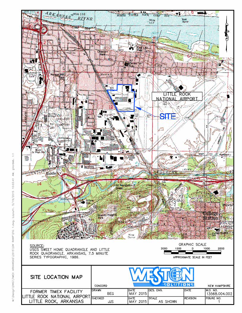
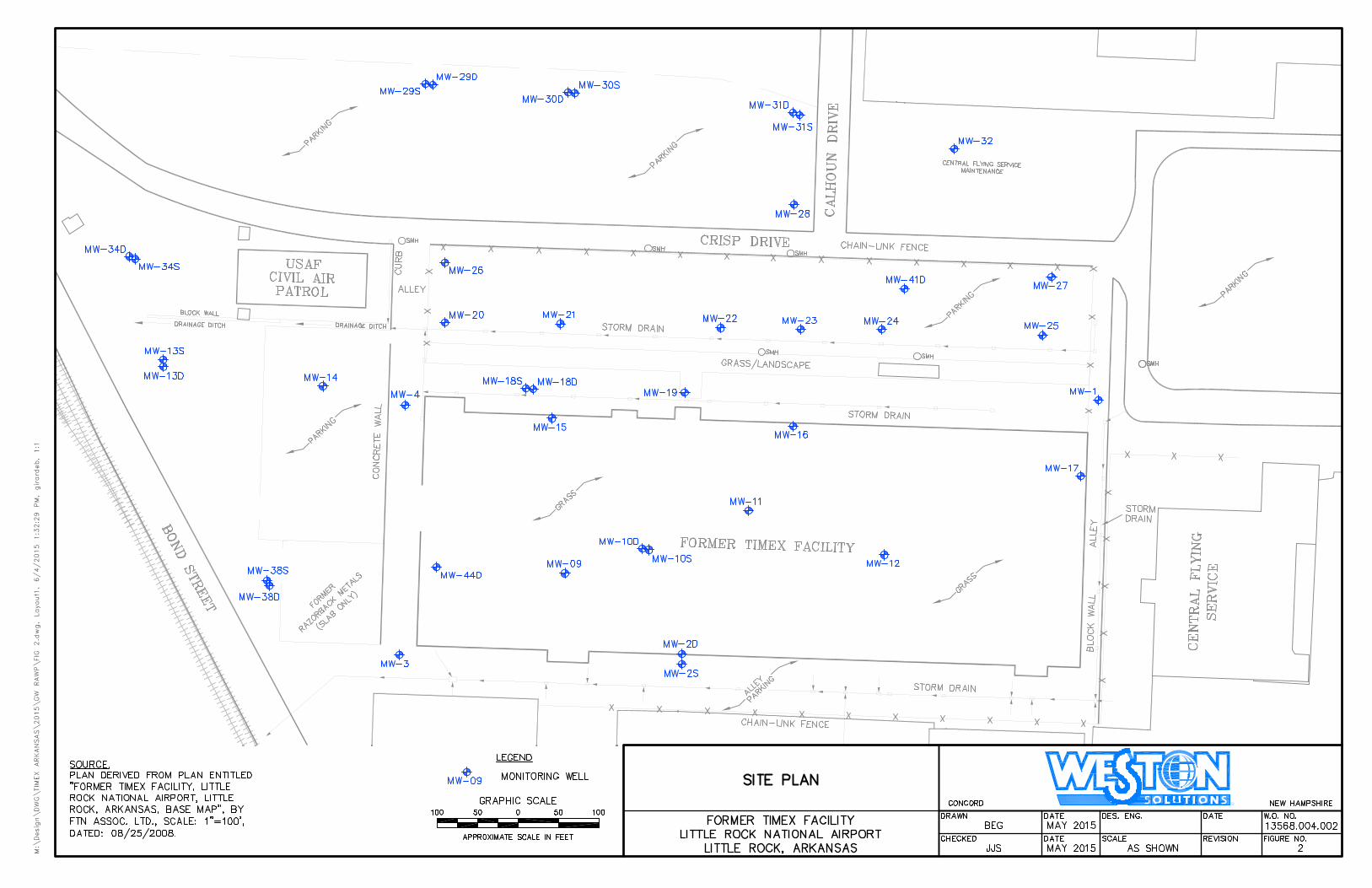
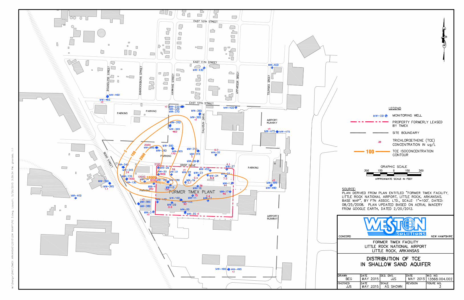
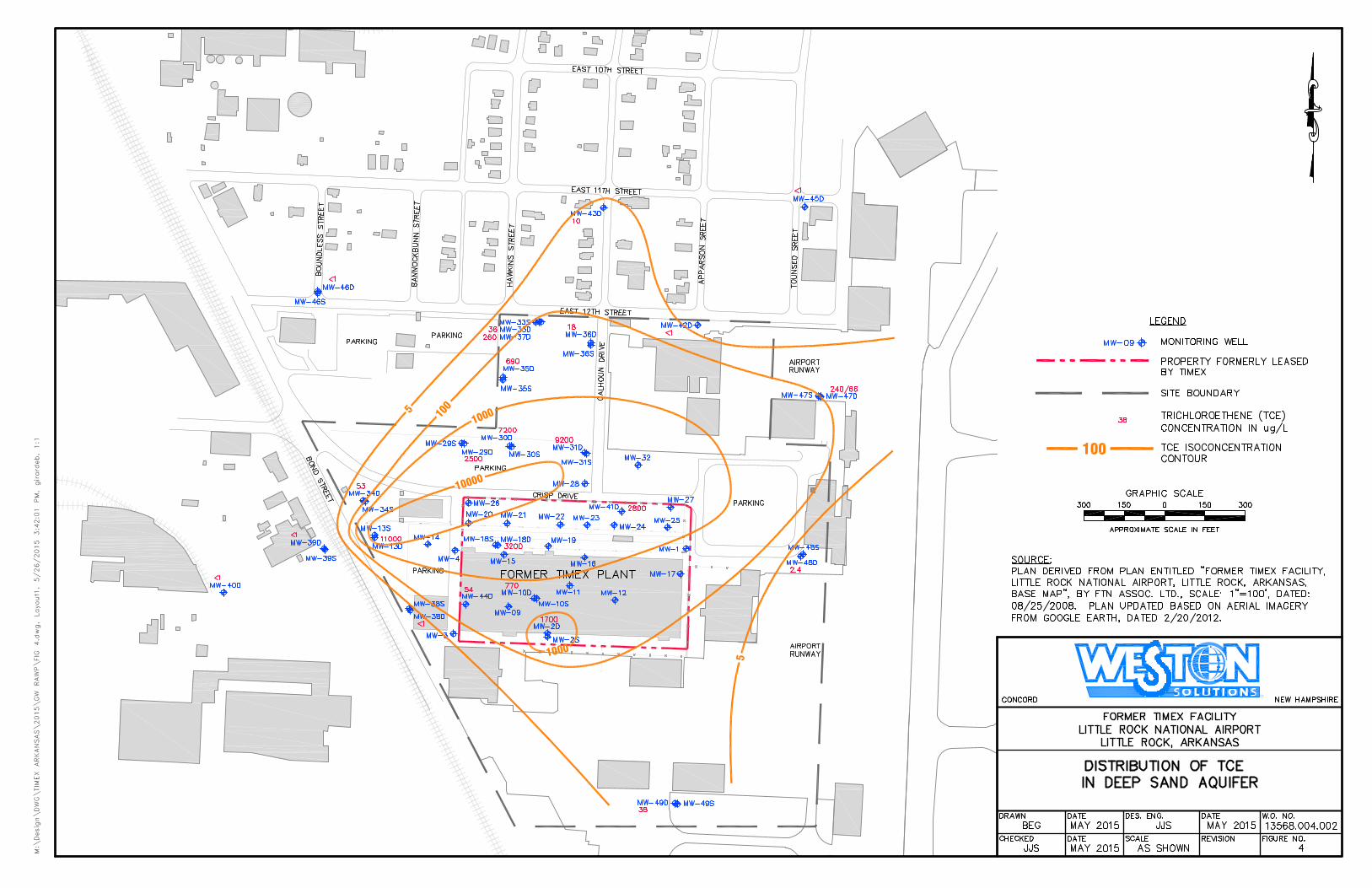
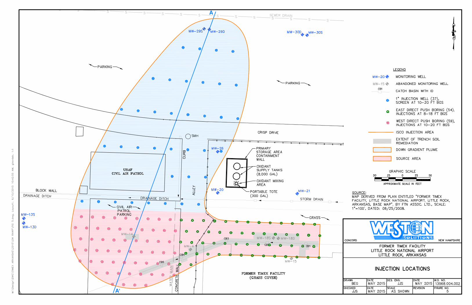
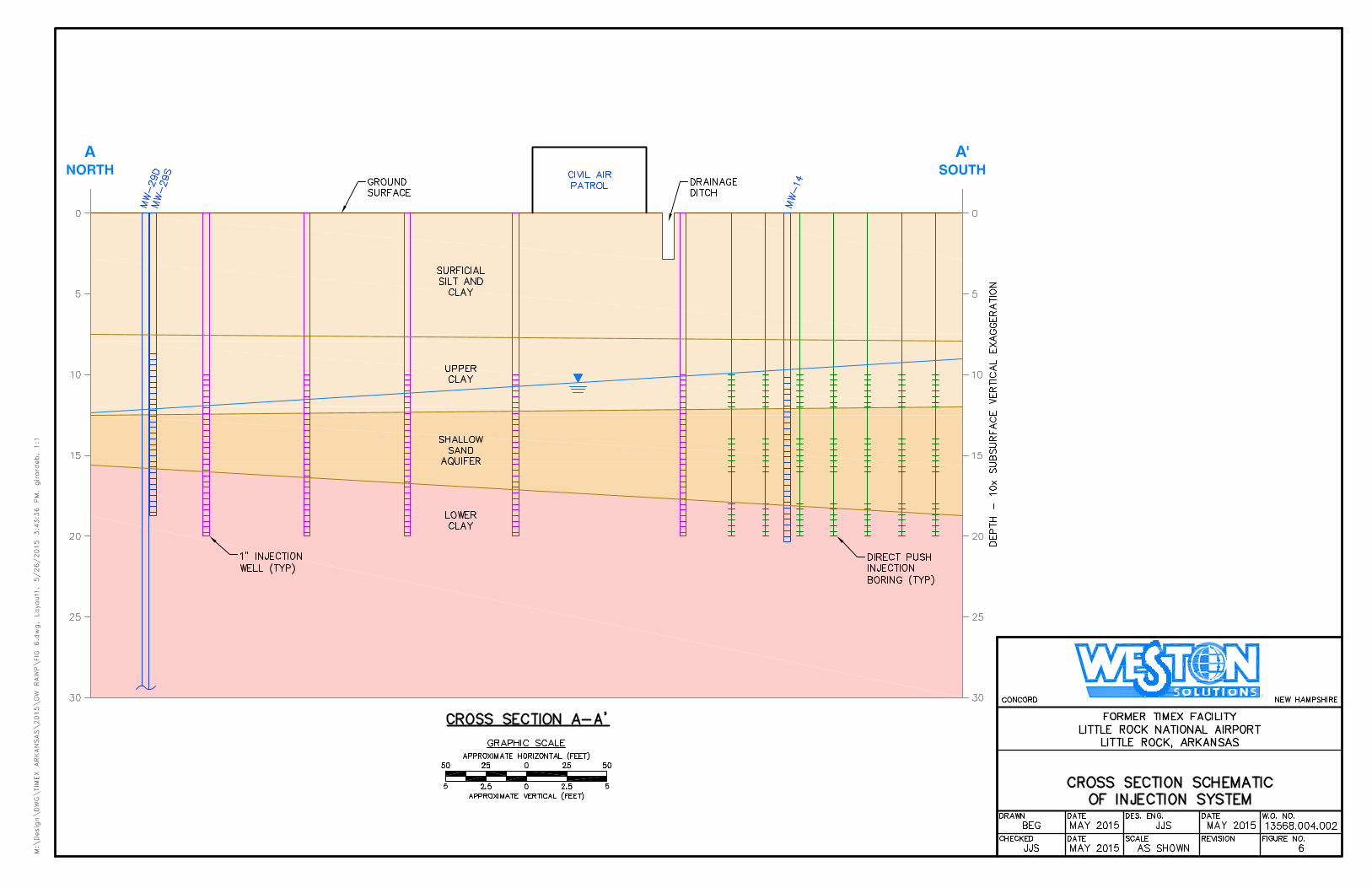
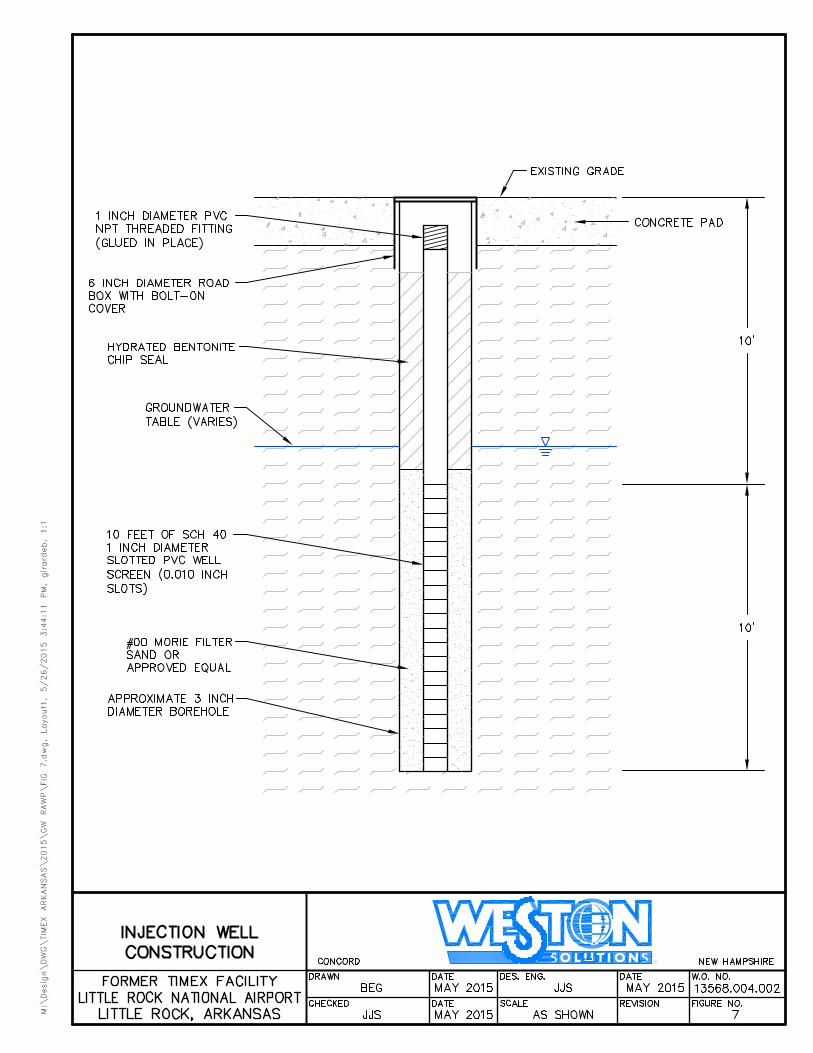
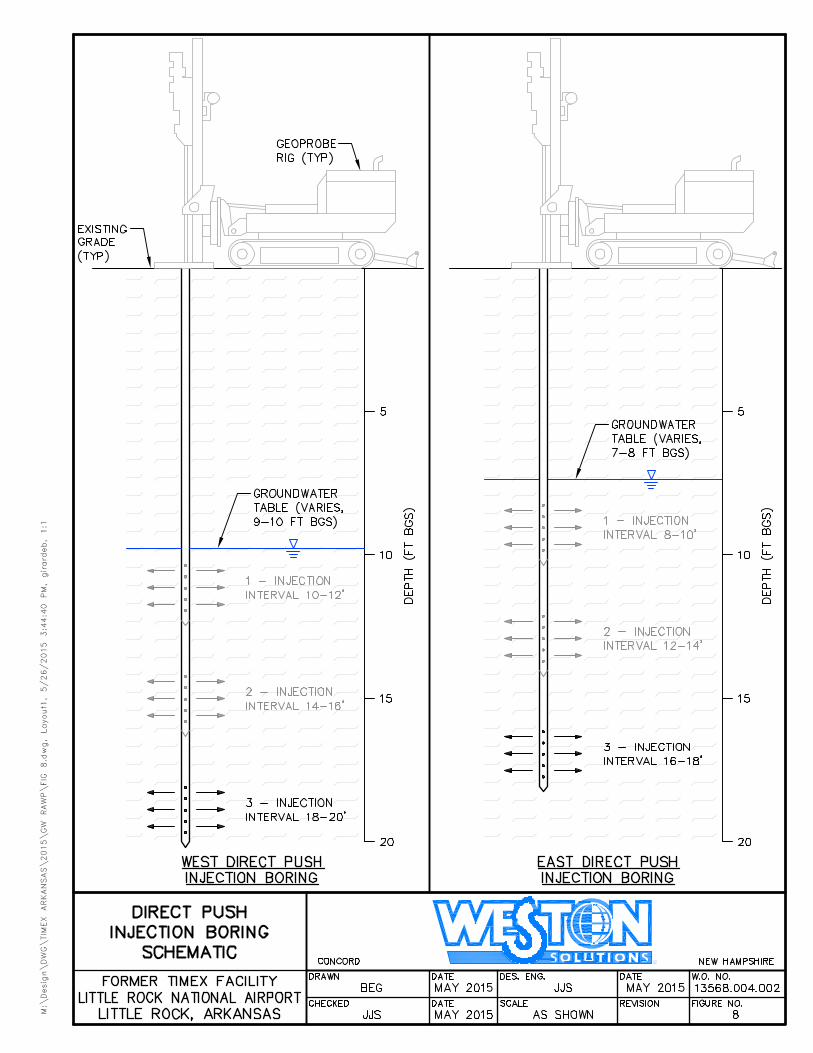
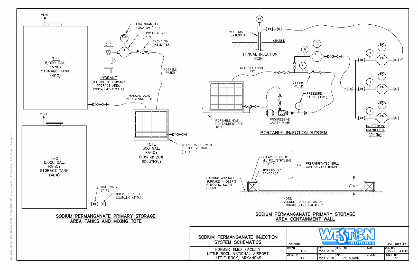
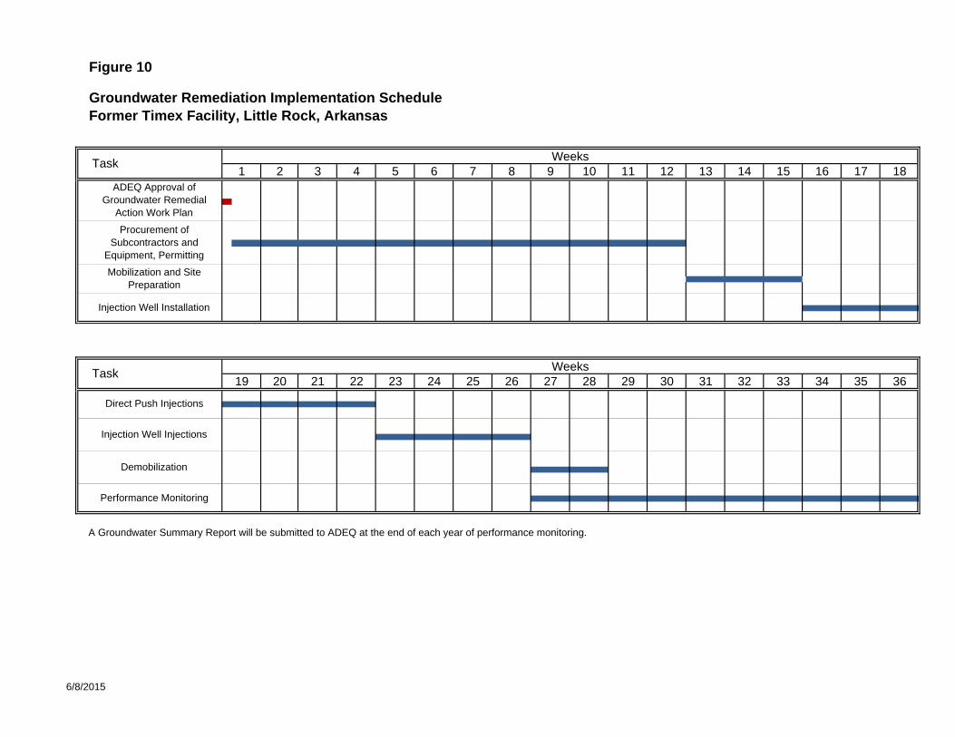
Figure 10
Groundwater Remediation Implementation ScheduleFormer Timex Facility, Little Rock, Arkansas
A Groundwater Summary Report will be submitted to ADEQ at the end of each year of performance monitoring.
4 10 11 183 5 6 157 8 9 171413
Injection Well Installation
Procurement of Subcontractors and
Equipment, Permitting
Mobilization and Site Preparation
ADEQ Approval of Groundwater Remedial
Action Work Plan
161 2 12 Task
Weeks
36Weeks
19 20 21 22 23 24 25 26 32 33 34 3527 28 29 30
Demobilization
Injection Well Injections
Direct Push Injections
Performance Monitoring
Task31
6/8/2015
TABLES

Table 1Sodium Permanganate Injection Design
Source Area Treatment
Line Item Unit Value
1 Permanganate dose from pilot test g NaMnO4/1000g soil 2.0
2 Permanganate dose from pilot test lb NaMnO4/lb soil 0.002
3 Width of treatment zone ft 80
4 Length of treatment zone ft 512
5 Thickness of treatment zone ft 10
6 Volume of treatment zone ft3 409,600
7 Volume of treatment zone yd3 15,170
8 Unit weight of soil tons/yd3 1.50
9 Weight of soil in treatment zone tons 22,756
10 Weight of soil in treatment zone lb 45,511,111
11 Pounds of NaMnO4 per treatment zone lb 91,022
12 NaMnO4 solution strength % 40%
13 Pounds of 40% NaMnO4 solution needed lb 227,556
14 NaMnO4 density lb/gal 11.40
15 Total volume 40% NaMnO4 solution needed gal. 19,961.01
16 Water added to make 20% NaMnO4 solution gal. 27,546.20
17 Total volume 20% NaMnO4 solution to be injected gal. 47,507.21
18* Number of injection points (based on field pilot test) ea 113
19 40% solution needed for each well gal. 177
20 20% solution needed for each well gal. 420
Notes: * The number of injection points is based on the results of the field pilot test which suggested that a spacing of 20 ft is conservative.
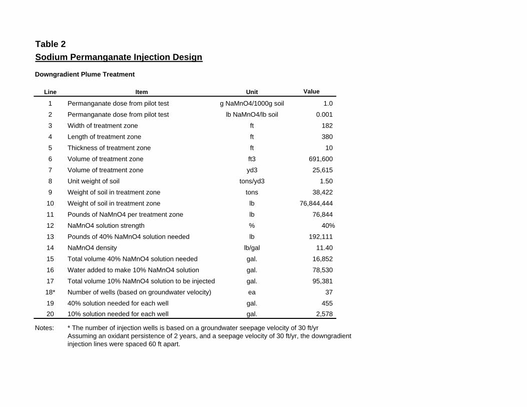
Table 2
Sodium Permanganate Injection Design
Downgradient Plume Treatment
Line Item Unit Value
1 Permanganate dose from pilot test g NaMnO4/1000g soil 1.0
2 Permanganate dose from pilot test lb NaMnO4/lb soil 0.001
3 Width of treatment zone ft 182
4 Length of treatment zone ft 380
5 Thickness of treatment zone ft 10
6 Volume of treatment zone ft3 691,600
7 Volume of treatment zone yd3 25,615
8 Unit weight of soil tons/yd3 1.50
9 Weight of soil in treatment zone tons 38,422
10 Weight of soil in treatment zone lb 76,844,444
11 Pounds of NaMnO4 per treatment zone lb 76,844
12 NaMnO4 solution strength % 40%
13 Pounds of 40% NaMnO4 solution needed lb 192,111
14 NaMnO4 density lb/gal 11.40
15 Total volume 40% NaMnO4 solution needed gal. 16,852
16 Water added to make 10% NaMnO4 solution gal. 78,530
17 Total volume 10% NaMnO4 solution to be injected gal. 95,381
18* Number of wells (based on groundwater velocity) ea 37
19 40% solution needed for each well gal. 455
20 10% solution needed for each well gal. 2,578
Notes: * The number of injection wells is based on a groundwater seepage velocity of 30 ft/yr Assuming an oxidant persistence of 2 years, and a seepage velocity of 30 ft/yr, the downgradient injection lines were spaced 60 ft apart.
APPENDIX A
MATERIAL SAFETY DATA SHEET

LIQUOX® sodium permanganate is a liquid oxidant recommended
for use in Electronics and Fine Chemical Synthesis, that require a
concentrated permanganate solution.
Assay40% minimum as NaMnO
4
pH5.0-8.0
Specific Gravity≥ 1.37
Insolubles≤ 0.005%
Formula NaMnO4
Appearance Deep Purple Solution
Shelf Life This product should be used within one year
of the date of production.
Decomposition may start at 150 °C / 302 °F
• Desmearing/Etchback - Printed circuit board desmearing and etchback.
• Oxidation and Synthesis - Organic chemicals and intermediates manufacture. Oxidizes impurities in organic and inorganic chemicals.
• Concentrated liquid oxidant
• More precise dosing of chemical
• Feed equipment is simplified
• Consistent concentration
• Dust problems are eliminated
• High solubility at room temperature
• Can be used whenever potassium ion cannot be tolerated
PRODUCT SPECIFICATIONS
BENEFITS
SHIPPING CONTAINERS5 gallon (18.9L) Tight Head HDPE Jerrican (UN Specification: 3H1) made of High Density Polyethylene
(HDPE), weighs 3.5 lb (1.6 kg). The net weight is 57 lb (25.7 kg).
The jerrican stands approximately 15.33 in. tall, 10.2 in. wide and
11.4 in. long (38.94 cm tall, 25.91 cm wide, 28.96 cm long).55-gallon (208.2L) HDPE TightHead Drum(UN Specification: UN1H1/Y1.9/150) Made of high-density
polyethylene (HDPE). Weighs 22 lbs (10 kg). The net weight is
550 lbs (249.5 kg). The drum stands approximately 34.5 in. tall, has
an outside diameter of 23.4 in. (89.1 cm tall, OD 59.4 cm).275-gallon (1040-L) IBC (Intermediate Bulk Container)(UN Specification: UN31HA1/Y1.9/100) They are also marked “MX” for multi-trip. IBC weighs 139-lbs (65-kg). The net weight is 3000-lbs (1360-kg). The IBC contains 263-gallons (1000-L) of product. The IBC dimensions are 45.4 in. high, 48 in. long, and 40 in. wide. The IBC has a 2” butterfly valve with NPT threads in bottom sump. (Domestic)
Like any strong oxidant, LIQUOX sodium permanganate should be
handled with care. Protective equipment during handling should
include face shields and/or goggles, rubber or plastic gloves, rubber
or plastic apron. If clothing becomes spotted, wash off
immediately; spontaneous ignition can occur with cloth or paper.
In cases where significant exposure exists, use of the appropriate
NIOSH-MSHA dust or mist respirator or an air supplied respirator
is advised.
The product should be stored in a dry area in closed containers.
Product should be stored above 50°F. Concrete floors are
preferred. Avoid wooden decks. Spillage should be collected and
disposed of properly. Contain and dilute spillage to approximately
6% with water and reduce with sodium thiosulfate, a bisulfite, or
ferrous salt. The bisulfite or ferrous salt may require dilute sulfuric
acid to promote reduction. Neutralize any acid used with sodium
bicarbonate. Deposit sludge in an approved landfill or, where
permitted, drain into sewer with large quantities of water.
As an oxidant, the product itself is non-combustible, but will
accelerate the burning of combustible materials. Therefore,
contact with all combustible materials and/or chemicals must be
avoided. These include, but are not limited to: wood, cloth, organic
chemicals, and charcoal. Avoid contact with acids, peroxides,
sulfites, oxalates, and all other oxidizable inorganic chemicals.
With hydrochloric acid, chlorine is liberated.
HANDLING, STORAGE, AND INCOMPATIBILITYCHEMICAL/PHYSICAL DATA
I N D U S T R I A L®
APPLICATIONS
Copyright 2012rev. 11/13Form LX 1501
The information contained herein is accurate to the best of our knowledge. However, data, safety standards and government regulations are subject to change; and the conditions of handling, use or misuse of the product are beyond our control. Carus Chemical Company makes no warranty, either expressed or implied, including any warranties of merchantability and fitness for a particular purpose. Carus also disclaims all liability for reliance on the completeness or confirming accuracy of any information included herein. Users should satisfy themselves that they are aware of all current data relevant to their particular use(s).
D A T A S H E E T
L I Q U O X ® S O D I U M P E R M A N G A N A T EC A S R e g i s t r y N o . 1 0 1 0 1 - 5 0 - 5
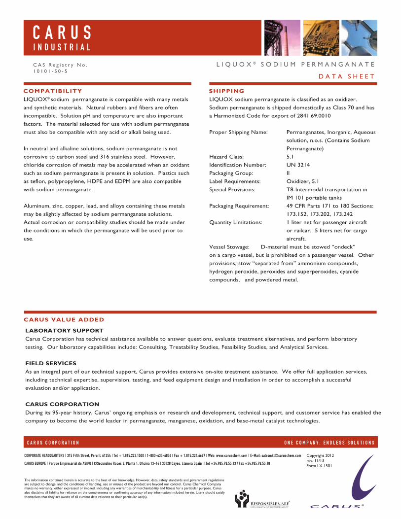
LIQUOX® sodium permanganate is compatible with many metals
and synthetic materials. Natural rubbers and fibers are often
incompatible. Solution pH and temperature are also important
factors. The material selected for use with sodium permanganate
must also be compatible with any acid or alkali being used.
In neutral and alkaline solutions, sodium permanganate is not
corrosive to carbon steel and 316 stainless steel. However,
chloride corrosion of metals may be accelerated when an oxidant
such as sodium permanganate is present in solution. Plastics such
as teflon, polypropylene, HDPE and EDPM are also compatible
with sodium permanganate.
Aluminum, zinc, copper, lead, and alloys containing these metals
may be slightly affected by sodium permanganate solutions.
Actual corrosion or compatibility studies should be made under
the conditions in which the permanganate will be used prior to
use.
LIQUOX sodium permanganate is classified as an oxidizer.
Sodium permanganate is shipped domestically as Class 70 and has
a Harmonized Code for export of 2841.69.0010
Proper Shipping Name: Permanganates, Inorganic, Aqueous
solution, n.o.s. (Contains Sodium
Permanganate)
Hazard Class: 5.1
Identification Number: UN 3214
Packaging Group: II
Label Requirements: Oxidizer, 5.1
Special Provisions: T8-Intermodal transportation in
IM 101 portable tanks
Packaging Requirement: 49 CFR Parts 171 to 180 Sections:
173.152, 173.202, 173.242
Quantity Limitations: 1 liter net for passenger aircraft
or railcar. 5 liters net for cargo
aircraft.
Vessel Stowage: D-material must be stowed “ondeck”
on a cargo vessel, but is prohibited on a passenger vessel. Other
provisions, stow “separated from” ammonium compounds,
hydrogen peroxide, peroxides and superperoxides, cyanide
compounds, and powdered metal.
COMPATIBILITY SHIPPING
CARUS VALUE ADDED
LABORATORY SUPPORTCarus Corporation has technical assistance available to answer questions, evaluate treatment alternatives, and perform laboratory
testing. Our laboratory capabilities include: Consulting, Treatability Studies, Feasibility Studies, and Analytical Services.
FIELD SERVICESAs an integral part of our technical support, Carus provides extensive on-site treatment assistance. We offer full application services,
including technical expertise, supervision, testing, and feed equipment design and installation in order to accomplish a successful
evaluation and/or application.
CARUS CORPORATIONDuring its 95-year history, Carus’ ongoing emphasis on research and development, technical support, and customer service has enabled the
company to become the world leader in permanganate, manganese, oxidation, and base-metal catalyst technologies.
Copyright 2012rev. 11/13Form LX 1501
The information contained herein is accurate to the best of our knowledge. However, data, safety standards and government regulations are subject to change; and the conditions of handling, use or misuse of the product are beyond our control. Carus Chemical Company makes no warranty, either expressed or implied, including any warranties of merchantability and fitness for a particular purpose. Carus also disclaims all liability for reliance on the completeness or confirming accuracy of any information included herein. Users should satisfy themselves that they are aware of all current data relevant to their particular use(s).
D A T A S H E E T
L I Q U O X ® S O D I U M P E R M A N G A N A T EC A S R e g i s t r y N o . 1 0 1 0 1 - 5 0 - 5