the pinnacle – design and construction of large diameter ... · this paper describes the design...
TRANSCRIPT
24 GROUND ENGINEERING November 2015
Technical paper
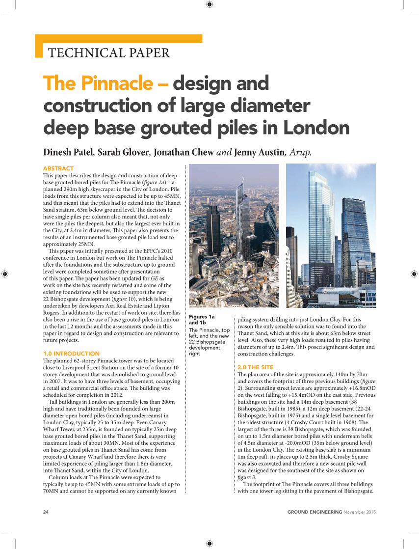
AbstRActThis paper describes the design and construction of deep base grouted bored piles for The pinnacle (figure 1a) – a planned 290m high skyscraper in the city of london. pile loads from this structure were expected to be up to 45Mn, and this meant that the piles had to extend into the Thanet Sand stratum, 63m below ground level. The decision to have single piles per column also meant that, not only were the piles the deepest, but also the largest ever built in the city, at 2.4m in diameter. This paper also presents the results of an instrumented base grouted pile load test to approximately 25Mn.
This paper was initially presented at the eFFc’s 2010 conference in london but work on The pinnacle halted after the foundations and the substructure up to ground level were completed sometime after presentation of this paper. The paper has been updated for GE as work on the site has recently restarted and some of the existing foundations will be used to support the new 22 Bishopsgate development (figure 1b), which is being undertaken by developers axa real estate and lipton rogers. in addition to the restart of work on site, there has also been a rise in the use of base grouted piles in london in the last 12 months and the assessments made in this paper in regard to design and construction are relevant to future projects.
1.0 INtRODUctION The planned 62-storey pinnacle tower was to be located close to liverpool Street Station on the site of a former 10 storey development that was demolished to ground level in 2007. it was to have three levels of basement, occupying a retail and commercial office space. The building was scheduled for completion in 2012.
Tall buildings in london are generally less than 200m high and have traditionally been founded on large diameter open bored piles (including underreams) in london clay, typically 25 to 35m deep. even canary Wharf Tower, at 235m, is founded on typically 25m deep base grouted bored piles in the Thanet Sand, supporting maximum loads of about 30Mn. Most of the experience on base grouted piles in Thanet Sand has come from projects at canary Wharf and therefore there is very limited experience of piling larger than 1.8m diameter, into Thanet Sand, within the city of london.
column loads at The pinnacle were expected to typically be up to 45Mn with some extreme loads of up to 70Mn and cannot be supported on any currently known
Dinesh Patel, Sarah Glover, Jonathan Chew and Jenny Austin, Arup.
the Pinnacle – design and construction of large diameter deep base grouted piles in London
piling system drilling into just london clay. For this reason the only sensible solution was to found into the Thanet Sand, which at this site is about 63m below street level. also, these very high loads resulted in piles having diameters of up to 2.4m. This posed significant design and construction challenges.
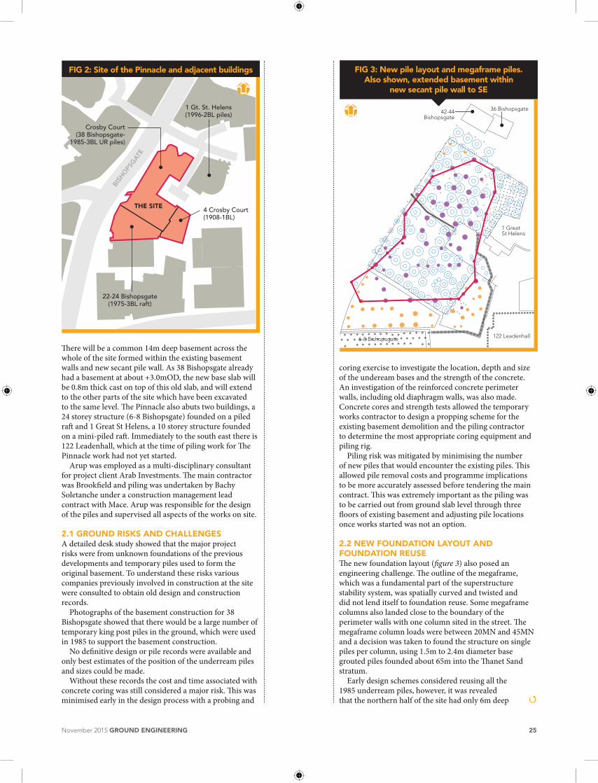
2.0 thE sItEThe plan area of the site is approximately 140m by 70m and covers the footprint of three previous buildings (figure 2). Surrounding street levels are approximately +16.8mOD on the west falling to +15.4mOD on the east side. previous buildings on the site had a 14m deep basement (38 Bishopsgate, built in 1985), a 12m deep basement (22-24 Bishopsgate, built in 1975) and a single level basement for the oldest structure (4 crosby court built in 1908). The largest of the three is 38 Bishopsgate, which was founded on up to 1.5m diameter bored piles with underream bells of 4.5m diameter at -20.0mOD (35m below ground level) in the london clay. The existing base slab is a minimum 1m deep raft, in places up to 2.5m thick. crosby Square was also excavated and therefore a new secant pile wall was designed for the southeast of the site as shown on figure 3.
The footprint of The pinnacle covers all three buildings with one tower leg sitting in the pavement of Bishopsgate.
Figures 1a and 1bThe Pinnacle, top left, and the new 22 Bishopsgate development, right
November 2015 GROUND ENGINEERING 25
There will be a common 14m deep basement across the whole of the site formed within the existing basement walls and new secant pile wall. as 38 Bishopsgate already had a basement at about +3.0mOD, the new base slab will be 0.8m thick cast on top of this old slab, and will extend to the other parts of the site which have been excavated to the same level. The pinnacle also abuts two buildings, a 24 storey structure (6-8 Bishopsgate) founded on a piled raft and 1 Great St helens, a 10 storey structure founded on a mini-piled raft. immediately to the south east there is 122 leadenhall, which at the time of piling work for The pinnacle work had not yet started.
arup was employed as a multi-disciplinary consultant for project client arab investments. The main contractor was Brookfield and piling was undertaken by Bachy Soletanche under a construction management lead contract with Mace. arup was responsible for the design of the piles and supervised all aspects of the works on site.
2.1 GROUND RIsks AND chALLENGEsa detailed desk study showed that the major project risks were from unknown foundations of the previous developments and temporary piles used to form the original basement. To understand these risks various companies previously involved in construction at the site were consulted to obtain old design and construction records.
photographs of the basement construction for 38 Bishopsgate showed that there would be a large number of temporary king post piles in the ground, which were used in 1985 to support the basement construction.
no definitive design or pile records were available and only best estimates of the position of the underream piles and sizes could be made.
Without these records the cost and time associated with concrete coring was still considered a major risk. This was minimised early in the design process with a probing and
FIG 3: New pile layout and megaframe piles.Also shown, extended basement within
new secant pile wall to SE
42-44Bishopsgate
36 Bishopsgate
1 GreatSt Helens
122 Leadenhall6-8 Bishopsgate
coring exercise to investigate the location, depth and size of the undeream bases and the strength of the concrete. an investigation of the reinforced concrete perimeter walls, including old diaphragm walls, was also made. concrete cores and strength tests allowed the temporary works contractor to design a propping scheme for the existing basement demolition and the piling contractor to determine the most appropriate coring equipment and piling rig.
piling risk was mitigated by minimising the number of new piles that would encounter the existing piles. This allowed pile removal costs and programme implications to be more accurately assessed before tendering the main contract. This was extremely important as the piling was to be carried out from ground slab level through three floors of existing basement and adjusting pile locations once works started was not an option.
2.2 NEw FOUNDAtION LAyOUt AND FOUNDAtION REUsEThe new foundation layout (figure 3) also posed an engineering challenge. The outline of the megaframe, which was a fundamental part of the superstructure stability system, was spatially curved and twisted and did not lend itself to foundation reuse. Some megaframe columns also landed close to the boundary of the perimeter walls with one column sited in the street. The megaframe column loads were between 20Mn and 45Mn and a decision was taken to found the structure on single piles per column, using 1.5m to 2.4m diameter base grouted piles founded about 65m into the Thanet Sand stratum.
early design schemes considered reusing all the 1985 underream piles, however, it was revealed that the northern half of the site had only 6m deep Q
FIG 2: Site of the Pinnacle and adjacent buildings
BISH
OPS
GAT
E
THE SITE
1 Gt. St. Helens(1996-2BL piles)
Crosby Court(38 Bishopsgate-
1985-3BL UR piles)
22-24 Bishopsgate(1975-3BL raft)
4 Crosby Court(1908-1BL)

26 GROUND ENGINEERING November 2015
Technical paper
reinforcement cages installed below the trim level of the underream piles. it was found that during basement excavation in 1985, all these piles cracked just below the reinforcement cage and had to be remediated before construction continued by coring and grouting. piles in the southern half were fully reinforced over the shaft and did not suffer from the same problem.
The implication for The pinnacle development was that foundation reuse could only be considered on the southern part of the site as the northern piles were likely to suffer further cracking due to an average short term net unloading of the site of about 200kpa. as a result, a mixture of new large diameter bored piles and minipiles, founded in london clay, were used in the northern half of the site.
2.3 GROUND cONDItIONsThe pinnacle site is underlain by up to 6m of made ground overlying about 3m of brickearth and Terrace Gravels. Underlying these superficial deposits are up to 35m of london clay, 18m of lambeth Group, 11m of Thanet Sand and chalk proved to 2m depth. The clays are underdrained due to the low groundwater table in the lower aquifer of the chalk in central london. a summary of the stratigraphy of the site with undrained shear strength is plotted on figure 4 and the piezometric pore pressure is given in figure 5.
arup’s experience at canary Wharf showed that it was important to understand the mineralogy of the Thanet Sand, as low bearing capacities could occur in sand with high silt/clay content. For this reason, the site investigation at The pinnacle considered profiling of the Thanet Sand as a crucial part of the pile design. This was achieved by
carrying out Ménard pressuremeter tests (figure 6a) and frequent pipette/sieve analysis of the Thanet Sand from high quality rotary cored samples (figure 6b).
The results of these tests show that the upper 7m of the Thanet Sand recorded high limiting pressures (19Mpa) and correspondingly low clay/silt mineralogy of less than 15% (referred to as “clean” sand). The lower 4m of the sand, referred to as “dirty” sand, has a higher mineralogy (> 20%) and limiting pressures reduce to about 11Mpa. These observations are similar to the conclusions made by nicholson et al (2002) in the Thanet Sands at canary Wharf.
From this investigation, the decision was taken to found all the base grouted piles at least 2m below the sand surface at -48.5mOD. The risk of piles not founding into the Thanet Sand, due to varying surface levels across the site, was not considered a major risk as there was a clear marker bed, the pebble Beds of the Upnor Formation, separating the interface between the lambeth Group and the Thanet Sand.
3.0 DEsIGN OF bAsE GROUtED PILEs The first major use of base grouted piles in Thanet Sand was developed for the buildings at canary Wharf, Docklands in the 1980s (Troughton 1989). This form of piling was well suited to these sites as the Thanet Sand was only about 30m below ground with mean effective stresses of 300 to 400kpa. Two methods of pile design evolved on these sites, one based on effective stress design, and the second using self boring and/or Ménard pressuremeter testing as described in more recent works (chapman et al 1999, nicholson et al 2002).
The base grouted piles at canary Wharf did not exceed 1.8m diameter and base grouting was carried out using a maximum of four grouting tube circuits or tube à manchettes (ie using eight grouting tubes) attached to a reinforcement cage. it was also possible to build these piles generally within 12 to 24 hours. Maximum loads on the piles were 32Mn, assuming a working stress of 12.5Mpa.
The early Thanet Sand piles at canary Wharf were constructed under bentonite, but later projects were
FIG 4: Undrained shear strength profile
0
Leve
l (m
OD
)
Red
uced
leve
l (m
OD
)
Undrained shear strength (kPa)
100 200 300 400 500 600-40
-10
-5
0
5
10
-30
-35
-25
-20
-15
-40
-10
0
10
20
-30
-20
BH 01
Cu = 100 + 6.4z
6.5
z
FIG 5: Piezometric pressures
0
Leve
l (m
OD
)
Red
uced
leve
l (m
OD
)
Pore pressure (kPa)
100 200 300 400 500 600-70
-30
-20
-10
0
10
20
-60
-50
-40
-60
-10
0
10
20
-30
-40
-50
-20
BH 01
London Clay
Lambeth Clay
Lambeth Sand
Thanet SandHydrostatic
from -30mOD
Hydrostaticfrom +7.4mOD
Q

November 2015 GROUND ENGINEERING 27
constructed in dry Thanet Sand, as it was dewatered for basement construction. The use of pile drilling augers and digging buckets under bentonite was thought to loosen the Thanet Sand, and base grouting was employed to restore the base stiffness (Yates and O’riordan, 1989).
in the city of london, there is very limited experience of piling up to 65m into saturated Thanet Sand. The Moorhouse development (Yeow et al, 2005) is the closet site to The pinnacle where 1.8m diameter base grouted piles were formed supporting a maximum of 35Mn column loads. pile loads expected at The pinnacle are significantly higher, up to 45Mn, meaning up to 2.4m diameter piles founded 65m below ground were required. Therefore this posed challenges to both the design and construction, which is discussed below.
early workshops with potential piling contractors indicated that piles of this size and depth would take much longer to build compared to Moorhouse, at about four days, and even longer if shaft or base coring of underream piles had to be carried out. as a result there was concern that low shaft frictions may occur in the overlying london clay and lambeth clay strata, compared with piles which typically took 12 to 24 hours to install.
The use of pairs of 1.8m diameter piles per column was considered as an alternative, however, this would have substantially increased shaft and base coring of existing underream piles (some shafts were fully reinforced), required more drilling out of steel king post obstructions, and more pre-drilling of the existing thick base slab. it would also have introduced significant pile caps and hence larger openings in the existing base slab. The construction managers also wanted to start superstructure construction off the pile heads while demolishing the basement top down, therefore large pile caps would have been time consuming to construct and would have delayed this programme. a piled raft solution was also considered but again the perimeter megaframe carried the majority of the structural loads and this frame was not sympathetic to such a foundation solution.
all the piles were base grouted to control total and differential settlement of the structure, mainly because the
piling solution was based on using single piles per column. a non-base grouted solution was considered too risky as it would rely on the driller’s ability to produce 100% of piles with no disturbance. all the piles were also sonically logged to check construction was in accordance with the specification.
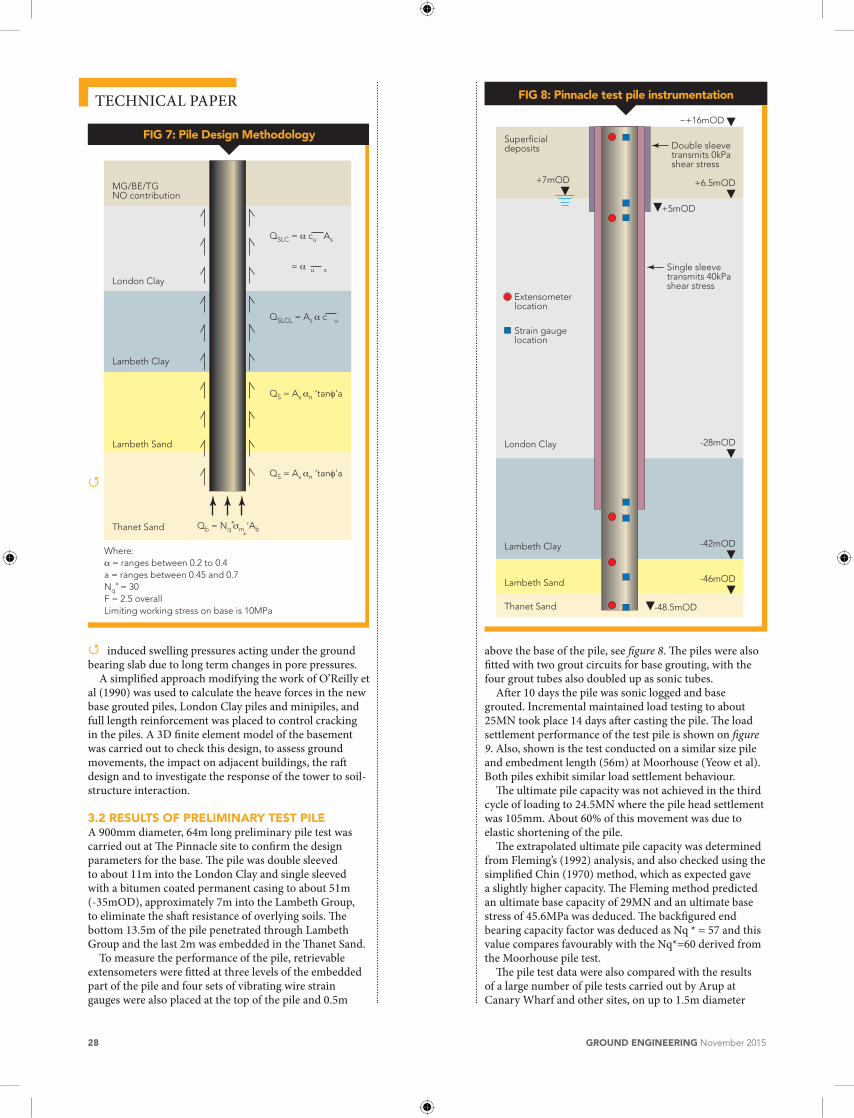
The pile design strategy developed for the project had to consider all these risks and the final design is illustrated in figure 7.
initial design was carried out using experience gained at canary Wharf and Moorhouse, where the end bearing capacity factor nq*, ranged between 30 and 60, from pile testing. at The pinnacle site, the mean effective stress at the pile toe is about 800kpa, and using the lower nq* factor results in an ultimate base stress of about 24Mpa. Thus, piles would be limited by the working stress on the concrete for an overall factor of safety of 2.5. Base grouted piles, which support the megaframe column loads, range between 1.5m and 2.4m diameter. For the largest pile diameters, up to 50% of the working load is carried on the grouted base.
an alternative design approach is to calculate the ultimate base stress from the limiting pressure derived from the Ménard pressuremeter test, using the approach: qb = λ. ρlim where, λ = factor to convert the Ménard limiting pressure to end bearing coefficientρlim = limiting pressure from Ménard pressuremeter
For this design approach, preliminary pile tests would have to be carried out to select an appropriate λ, value.
3.1 hEAvE AND sEttLEmENt AssEssmENts heave forces were generated in all the piles due to demolition of the existing buildings which exert forces of between 80kpa and 260kpa, areas of the site where new basements up to 14m were to be excavated and heave
FIG 6a: Limiting pressures from Menardpressure meter in Thanet Sand
0
Red
uced
leve
l (m
OD
)
Pressure (MPa)5 10 15 20 25
-56
-49
-48
-47
-46
-53
-52
-55
-54
-51
-50
-45Pl = 10MPa Pl = 20MPa
Toe-48.5mODPlim ~ 18MPa for clay/
silt fraction less than 15%
FIG 6b: Clay/silt fraction (%) of Thanet Sand
0
Red
uced
leve
l (m
OD
)
Clay and silt content (%)
20 40 60-56
-49
-48
-47
-46
-53
-52
-55
-54
-51
-50
-45
Toe-48.5mOD
Q
28 GROUND ENGINEERING November 2015
Technical paper
induced swelling pressures acting under the ground bearing slab due to long term changes in pore pressures.
a simplified approach modifying the work of O’reilly et al (1990) was used to calculate the heave forces in the new base grouted piles, london clay piles and minipiles, and full length reinforcement was placed to control cracking in the piles. a 3D finite element model of the basement was carried out to check this design, to assess ground movements, the impact on adjacent buildings, the raft design and to investigate the response of the tower to soil-structure interaction.
3.2 REsULts OF PRELImINARy tEst PILE a 900mm diameter, 64m long preliminary pile test was carried out at The pinnacle site to confirm the design parameters for the base. The pile was double sleeved to about 11m into the london clay and single sleeved with a bitumen coated permanent casing to about 51m (-35mOD), approximately 7m into the lambeth Group, to eliminate the shaft resistance of overlying soils. The bottom 13.5m of the pile penetrated through lambeth Group and the last 2m was embedded in the Thanet Sand.
To measure the performance of the pile, retrievable extensometers were fitted at three levels of the embedded part of the pile and four sets of vibrating wire strain gauges were also placed at the top of the pile and 0.5m
above the base of the pile, see figure 8. The piles were also fitted with two grout circuits for base grouting, with the four grout tubes also doubled up as sonic tubes.
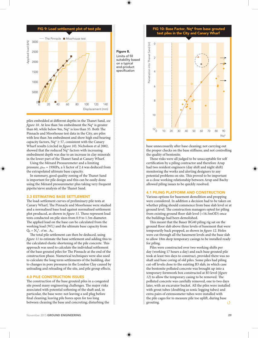
after 10 days the pile was sonic logged and base grouted. incremental maintained load testing to about 25Mn took place 14 days after casting the pile. The load settlement performance of the test pile is shown on figure 9. also, shown is the test conducted on a similar size pile and embedment length (56m) at Moorhouse (Yeow et al). Both piles exhibit similar load settlement behaviour.
The ultimate pile capacity was not achieved in the third cycle of loading to 24.5Mn where the pile head settlement was 105mm. about 60% of this movement was due to elastic shortening of the pile.
The extrapolated ultimate pile capacity was determined from Fleming’s (1992) analysis, and also checked using the simplified chin (1970) method, which as expected gave a slightly higher capacity. The Fleming method predicted an ultimate base capacity of 29Mn and an ultimate base stress of 45.6Mpa was deduced. The backfigured end bearing capacity factor was deduced as nq * = 57 and this value compares favourably with the nq*=60 derived from the Moorhouse pile test.
The pile test data were also compared with the results of a large number of pile tests carried out by arup at canary Wharf and other sites, on up to 1.5m diameter
FIG 7: Pile Design Methodology
London Clay
MG/BE/TGNO contribution
Lambeth Clay
Lambeth Sand
Thanet Sand
Where:α = ranges between 0.2 to 0.4a = ranges between 0.45 and 0.7Nq
∗ = 30F = 2.5 overallLimiting working stress on base is 10MPa
QSLC = α cu As
QSLCL = As α c u
QS = As αn ‘tanφ’a
QS = As αn ‘tanφ’a
Qb = Nq σm ‘Ab
= α u s
∗
∗
FIG 8: Pinnacle test pile instrumentation
London Clay
Superficialdeposits
Lambeth Clay
Lambeth Sand
Thanet Sand
-28mOD
+6.5mOD
~+16mOD
+7mOD
Extensometerlocation
Double sleevetransmits 0kPashear stress
Strain gaugelocation
-42mOD
-46mOD
-48.5mOD
+5mOD
Single sleevetransmits 40kPashear stress
Q
Q
November 2015 GROUND ENGINEERING 29
Figure 8. Limits of fill suitability based on a typical end-product specification
piles embedded at different depths in the Thanet Sand, see figure 10. at less than 5m embedment the nq* is greater than 60, while below 9m, nq* is less than 35. Both The pinnacle and Moorhouse test data in the city, are piles with less than 3m embedment and show high end bearing capacity factors, nq* ≥ 57, consistent with the canary Wharf results (circled in figure 10). nicholson et al 2002, showed that the reduced nq* factors with increasing embedment depth was due to an increase in clay minerals in the lower part of the Thanet Sand at canary Wharf.
Using the Ménard pressuremeter and a limiting pressure, ρlim = 19Mpa, a λ factor of 2.4 was deduced from the extrapolated ultimate base capacity.
in summary, good quality zoning of the Thanet Sand is important for pile design and this can be easily done using the Ménard pressuremeter plus taking very frequent pipette/sieve analysis of the Thanet Sand.
3.3 EstImAtING bAsE sEttLEmENt The load-settlement curves of preliminary pile tests at canary Wharf, The pinnacle and Moorhouse were studied and a normalised base load against normalised settlement plot produced, as shown in figure 11. These represent load tests conducted on pile sizes from 0.9 to 1.5m diameter. The applied load on the base can be calculated from the working load (Wl) and the ultimate base capacity from Qb = nq*. σ'm . ab.
The total pile settlement can then be deduced, using figure 11 to estimate the base settlement and adding this to the calculated elastic shortening of the pile concrete. This approach was used to calculate the individual settlement of the base grouted piles for The pinnacle at the end of the construction phase. numerical techniques were also used to calculate the long term settlements of the building, due to changes in pore pressures in the london clay caused by unloading and reloading of the site, and pile group effects.
4.0 PILE cONstRUctION IssUEsThe construction of the base grouted piles in a congested site posed many engineering challenges. The major risks associated with potential softening of the shaft and, in particular, the base were: not leaving a soil plug before final cleaning; leaving pile bores open for too long between cleaning the base and concreting; disturbing the
base unnecessarily after base cleaning; not carrying out the proper checks on the base stiffness; and not controlling the quality of bentonite.
These risks were all judged to be unacceptable for self certification by a piling contractor and therefore arup had two resident engineers (day shift and night shift) monitoring the works and alerting designers to any potential problems on site. This proved to be important as a close working relationship between arup and Bachy allowed piling issues to be quickly resolved.
4.1 PILING PLAtFORm AND cONstRUctION Various options for basement demolition and propping were considered. in addition a decision had to be taken on whether piling should commence from base slab level or at ground level. The construction managers opted for piling from existing ground floor slab level (+16.5mOD) once the buildings had been demolished.
This meant that the Bauer BG40 piling rig sat on the ground floor slab above three levels of basement that were temporarily back propped, as shown in figure 12. holes were cut through all the basement levels and the base slab to allow 18m deep temporary casings to be installed ready for piling.
piles were constructed over two working shifts per day (working 17 hours a day) and each base grouted pile took at least two days to construct, provided there was no shaft and base coring of old piles. Some piles had piling cut-off levels close to the existing B3 slab, in which case the bentonite polluted concrete was brought up into a temporary formwork box constructed at B3 level (figure 12) to allow the temporary casing to be removed. The polluted concrete was carefully removed, one to two days later, with an excavator bucket. all the piles were installed with grout tubes (doubling as sonic logging tubes) and extra pairs of extensometer tubes were installed with the pile cages for to measure pile toe uplift, during base grouting.
FIG 9: Load settlement plot of test pile
0
Ap
plie
d lo
ad (k
N)
Displacement (mm)
20 40 60 80 100 120 1400
1000
5000
1500
2000
2500
3000The Pinnacle Moorhouse test
FIG 10: Base Factor, Nq* from base groutedtest piles in the City and Canary Wharf
0
Pene
trat
ion
into
Tha
net
Sand
(m)
Nq*
10 20 30 40 50 60 70 80 9012
8
10
6
4
2
0
Q

30 GROUND ENGINEERING November 2015
Technical paper
4.2 tUbE à mANchEttE (tAm) ARRANGEmENtsprevious experience with successful base grouting of piles was for piles up to 1.8m diameter, where four grout circuits (eight tubes total) are used. The maximum grout area potentially covered by these circuits is about 0.6m², and the maximum grout reach is about 0.6m to the pile centre.
To ensure the same coverage of grout area and reach, the 2.1m diameter piles were fitted with six TaMs, and the 2.4m diameter piles with eight TaMs. a second reinforcing cage was avoided by moving four of the outer eight TaMs into the centre of the pile over the bottom 10m. The outer TaM circuits continued to the base and were also used to sonic log each pile before grouting.
The piling contractor tightly controlled the quality of the bentonite through all stages of the piling and table 1 shows the results of these site tests against the specification limits, as given in BS en 1538:2000.
4.3 RANkING systEm FOR bAsE GROUtED PILEs a non-circular flat bladed cleaning bucket was used to cut the final 150mm of the pile base. This special bucket reduced the suctions generated at the base during bucket extraction and it also had holes on the side so that bentonite fluid could runaway.
Following this operation, a 100mm square metal plate attached to a length of fabric tape measure was lowered to the base of the pile to check the base hardness. This was done immediately after base cleaning and after installation of the cage (just prior to concreting). The last measurement was taken to score the base hardness using a ranking system developed specifically for The pinnacle site, see table 2.
Scores were given for an ok, firm or hard base by the resident engineer. in the same way marks for grout pressures, grout take and base uplift (measured with extensometers located at the pile toe), were combined to
tAbLE 1: bs EN 1538:2000 bENtONItE LImIts
Property
Stages
FreshReady
for re-use
Before concre-
tingSite Results
Density (g/ml) <1.10 <1.25 <1.15 1.05 – 1.1
Marsh Value (s)
32 to 50 32 to 60 32 to 50 30-40
Fluid Loss (ml) <30 <50 N/A 14-18
pH 7-11 1-12 N/A As spec
Sand Content N/A N/A <4 0.25 – 2.0
Filter Cake (mm) <3 < 6 N/A <1
After BS EN 1538: 2000 Table1 – Execution of Special Geotechnical Works - DWs
give an overall ranking score. Grout volume was estimated for each pile size and
ranked according to the actual grout take. if the peak grout pressure was less than 30bar on each circuit during the first grouting phase then the pile was to be regrouted, up to a limit of three grouting operations including the initial operation.
a minimum of three hours was allowed between each round of grouting. Using this ranking system a minimum score of seven out of a possible 15 was considered as an acceptable pile.
FIG 11: Normalised base load and settlement plot
0
P bas
e/P u
lt b
ase
Base settlement/D (%)
1 2 3 4 5 60
0.3
0.2
0.1
0.4
0.5
0.6
0.7
HQ contract pile
Definitions:Pbase – load applied on basePult base – ultimate base capacity (Qb)D – Base diameter
HQ4bHQ3A
P152P60
MoorhousePinnacle - extrapolatedP140
P416
FIG 12: Piling from existing basement ground slab
Completedpile
Edge protection
Additional temporaryprops andexisting columns
Minipile rig
Rotary boredpiling rig
Temporary pile casing
Piling platform
Dial gauge
Referencebeam
Base grouting pump
London clay
Existing ground floor slab
Existing B1 slab
Existing B2 slab
ExistingB3 slab
Q
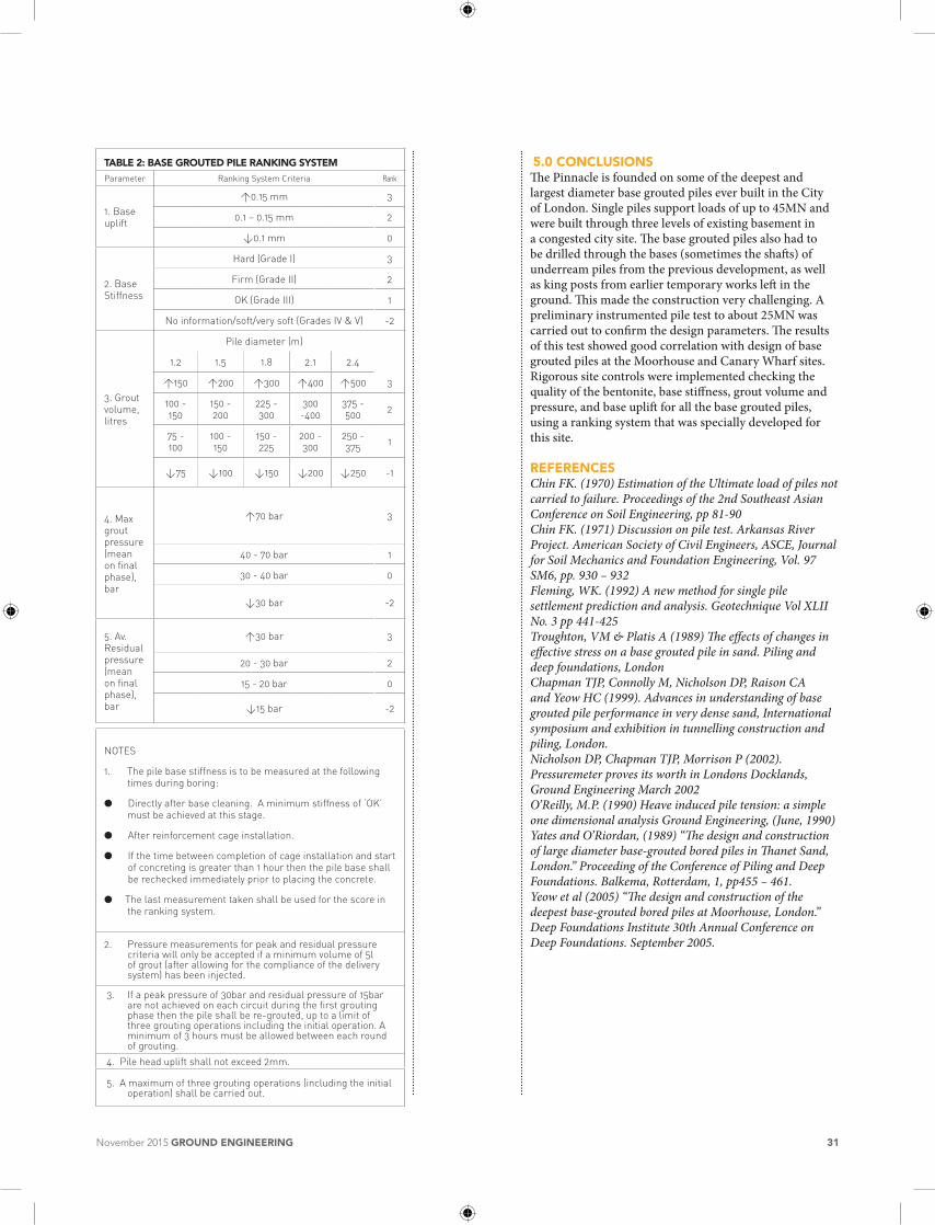
tAbLE 2: bAsE GROUtED PILE RANkING systEm
Parameter Ranking System Criteria Rank
1. Base uplift
>0.15 mm 3
0.1 – 0.15 mm 2
<0.1 mm 0
2. Base Stiffness
Hard (Grade I) 3
Firm (Grade II) 2
OK (Grade III) 1
No information/soft/very soft (Grades IV & V) -2
3. Grout volume, litres
Pile diameter (m)
1.2 1.5 1.8 2.1 2.4
>150 >200 >300 >400 >500 3
100 - 150
150 - 200
225 - 300
300 -400
375 - 500 2
75 - 100
100 - 150
150 - 225
200 - 300
250 - 375 1
<75 <100 <150 <200 <250 -1
4. Max grout pressure (mean on final phase), bar
>70 bar 3
40 - 70 bar 1
30 - 40 bar 0
<30 bar -2
5. Av. Residual pressure (mean on final phase), bar
>30 bar 3
20 - 30 bar 2
15 - 20 bar 0
<15 bar -2
NOTES
1. The pile base stiffness is to be measured at the following times during boring:
● Directly after base cleaning. A minimum stiffness of ‘OK’ must be achieved at this stage.
● After reinforcement cage installation.
● If the time between completion of cage installation and start of concreting is greater than 1 hour then the pile base shall be rechecked immediately prior to placing the concrete.
● The last measurement taken shall be used for the score in the ranking system.
2. Pressure measurements for peak and residual pressure criteria will only be accepted if a minimum volume of 5l of grout (after allowing for the compliance of the delivery system) has been injected.
3. If a peak pressure of 30bar and residual pressure of 15bar are not achieved on each circuit during the first grouting phase then the pile shall be re-grouted, up to a limit of three grouting operations including the initial operation. A minimum of 3 hours must be allowed between each round of grouting.
4. Pile head uplift shall not exceed 2mm.
5. A maximum of three grouting operations (including the initial operation) shall be carried out.
5.0 cONcLUsIONs The pinnacle is founded on some of the deepest and largest diameter base grouted piles ever built in the city of london. Single piles support loads of up to 45Mn and were built through three levels of existing basement in a congested city site. The base grouted piles also had to be drilled through the bases (sometimes the shafts) of underream piles from the previous development, as well as king posts from earlier temporary works left in the ground. This made the construction very challenging. a preliminary instrumented pile test to about 25Mn was carried out to confirm the design parameters. The results of this test showed good correlation with design of base grouted piles at the Moorhouse and canary Wharf sites. rigorous site controls were implemented checking the quality of the bentonite, base stiffness, grout volume and pressure, and base uplift for all the base grouted piles, using a ranking system that was specially developed for this site.
REFERENcEsChin FK. (1970) Estimation of the Ultimate load of piles not carried to failure. Proceedings of the 2nd Southeast Asian Conference on Soil Engineering, pp 81-90Chin FK. (1971) Discussion on pile test. Arkansas River Project. American Society of Civil Engineers, ASCE, Journal for Soil Mechanics and Foundation Engineering, Vol. 97 SM6, pp. 930 – 932Fleming, WK. (1992) A new method for single pile settlement prediction and analysis. Geotechnique Vol XLII No. 3 pp 441-425Troughton, VM & Platis A (1989) The effects of changes in effective stress on a base grouted pile in sand. Piling and deep foundations, London Chapman TJP, Connolly M, Nicholson DP, Raison CA and Yeow HC (1999). Advances in understanding of base grouted pile performance in very dense sand, International symposium and exhibition in tunnelling construction and piling, London. Nicholson DP, Chapman TJP, Morrison P (2002). Pressuremeter proves its worth in Londons Docklands, Ground Engineering March 2002 O’Reilly, M.P. (1990) Heave induced pile tension: a simple one dimensional analysis Ground Engineering, (June, 1990)Yates and O’Riordan, (1989) “The design and construction of large diameter base-grouted bored piles in Thanet Sand, London.” Proceeding of the Conference of Piling and Deep Foundations. Balkema, Rotterdam, 1, pp455 – 461.Yeow et al (2005) “The design and construction of the deepest base-grouted bored piles at Moorhouse, London.” Deep Foundations Institute 30th Annual Conference on Deep Foundations. September 2005.
November 2015 GROUND ENGINEERING 31