the millstone ii steam generator replacement … generator replacement-design of … · 8. after...
TRANSCRIPT
MAXIMUM REACH ENTERPRISES 1853 Wellington Court
Henderson, NV 89014
Ph: 702 547 1564
kent.goodman @ cox.net
www.maximumreach.com
07 June 2012
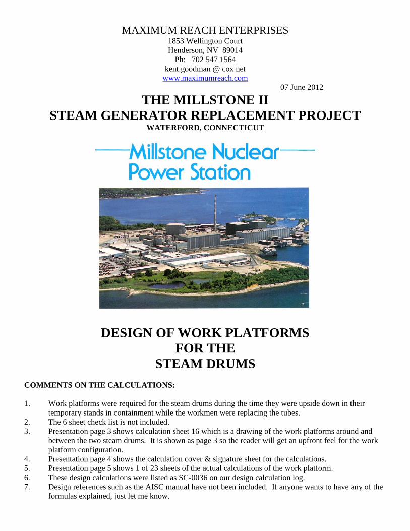
THE MILLSTONE II
STEAM GENERATOR REPLACEMENT PROJECT WATERFORD, CONNECTICUT
DESIGN OF WORK PLATFORMS
FOR THE
STEAM DRUMS
COMMENTS ON THE CALCULATIONS:
1. Work platforms were required for the steam drums during the time they were upside down in their
temporary stands in containment while the workmen were replacing the tubes.
2. The 6 sheet check list is not included.
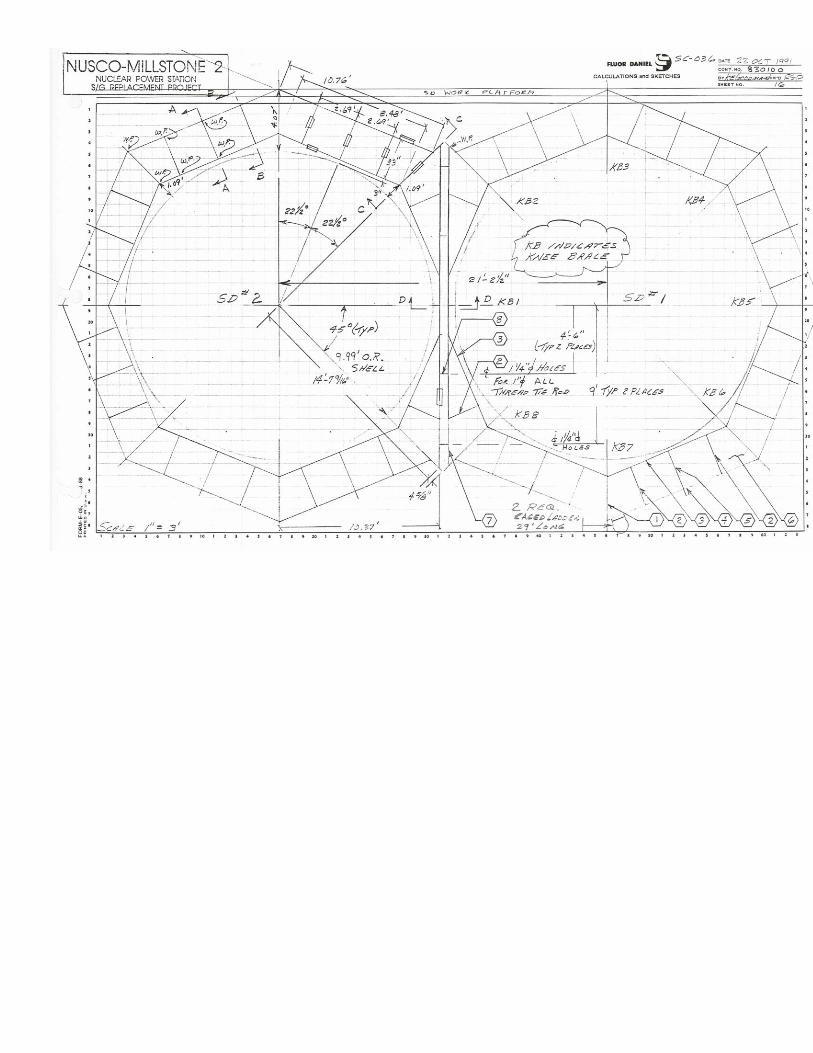
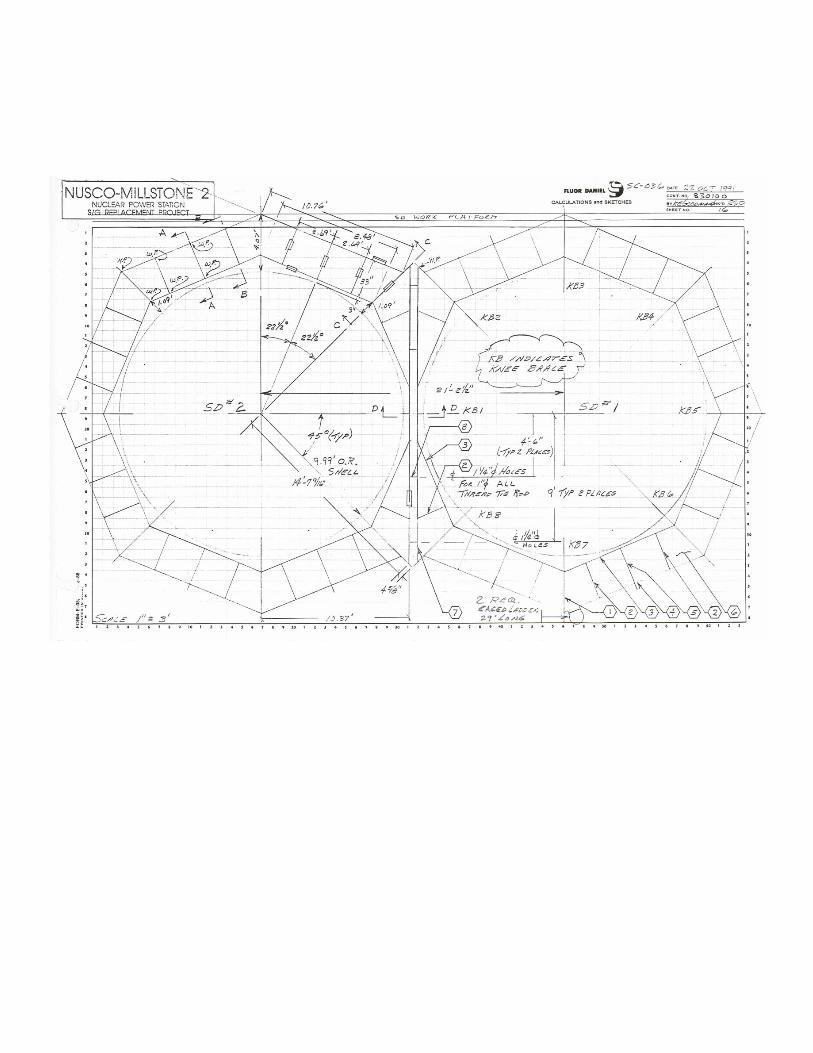
3. Presentation page 3 shows calculation sheet 16 which is a drawing of the work platforms around and
between the two steam drums. It is shown as page 3 so the reader will get an upfront feel for the work
platform configuration.
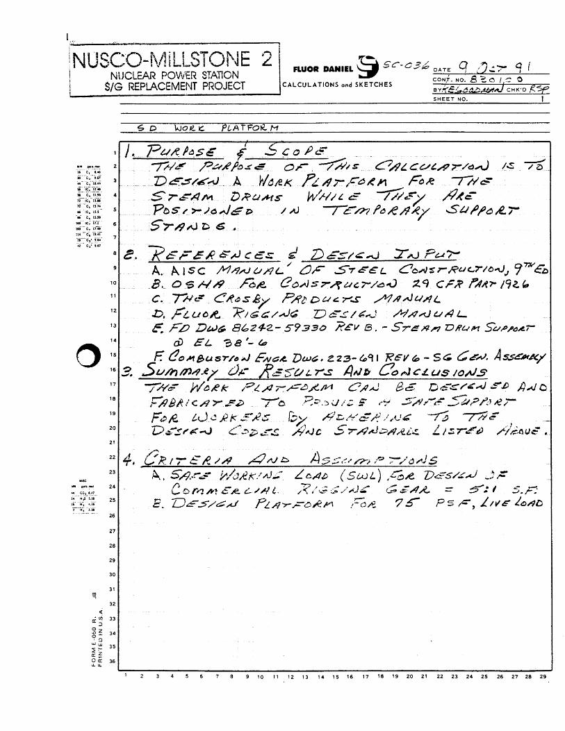
4. Presentation page 4 shows the calculation cover & signature sheet for the calculations.
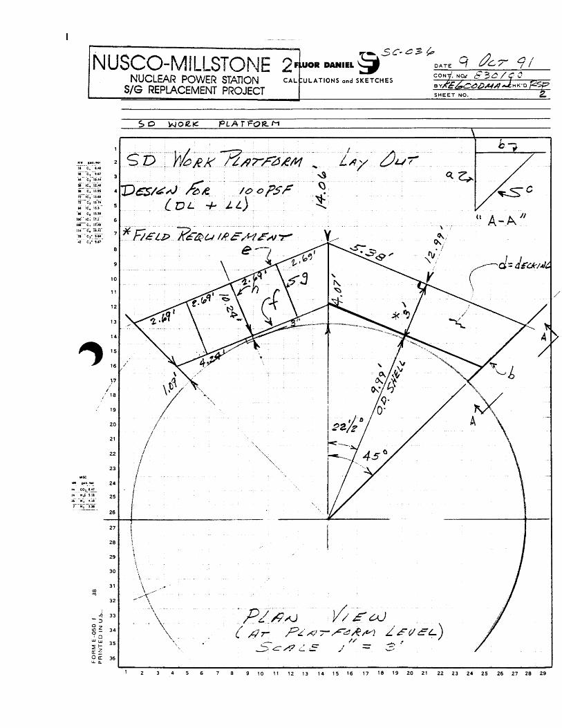
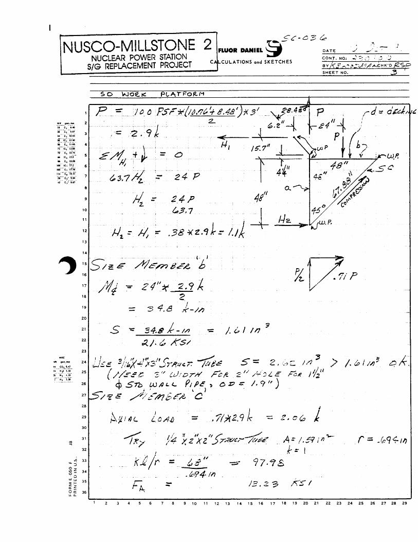
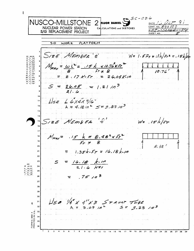
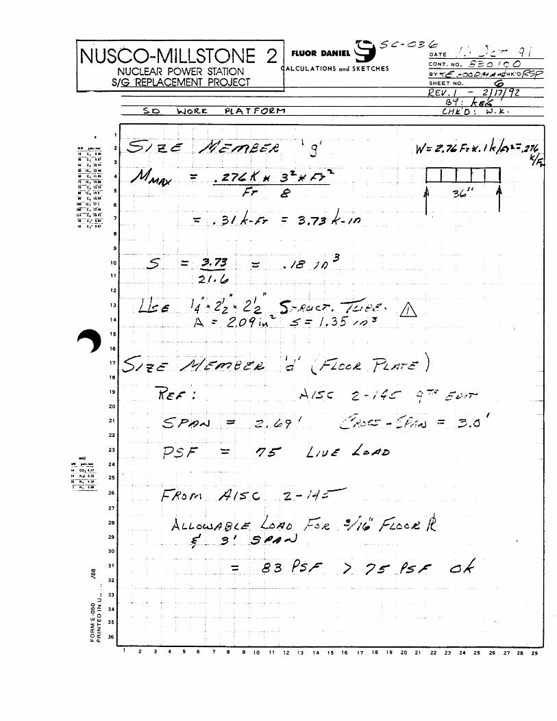
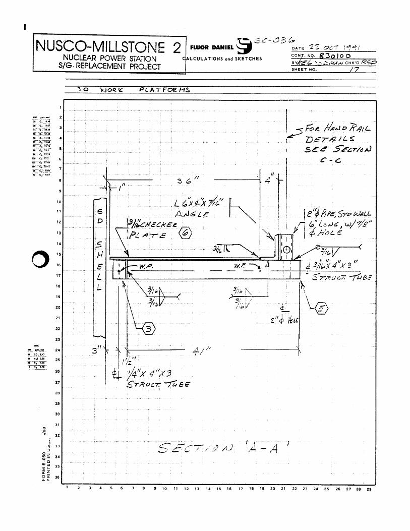
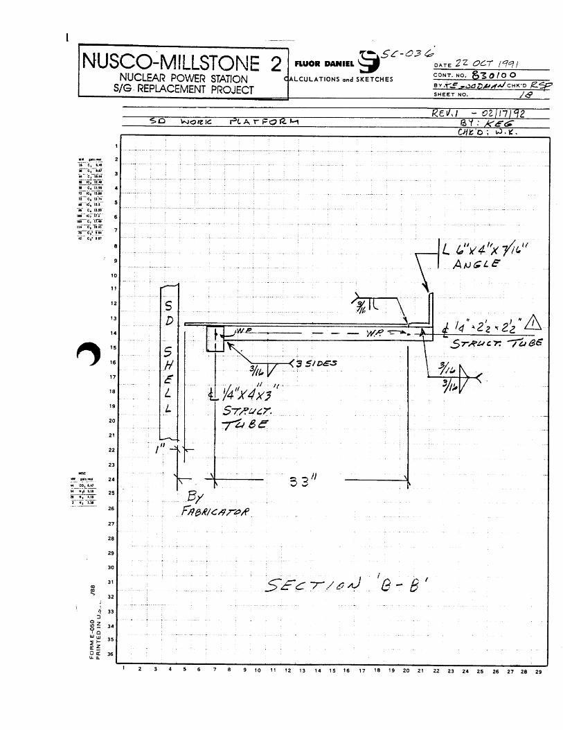
5. Presentation page 5 shows 1 of 23 sheets of the actual calculations of the work platform.
6. These design calculations were listed as SC-0036 on our design calculation log.
7. Design references such as the AISC manual have not been included. If anyone wants to have any of the
formulas explained, just let me know.

8. After sending out the “Scaffold Bracket Design”, Mick Podolski commented that my use of wire rope
for the hand rails would not be acceptable in Australia. He pointed out that hard pipe must be used that
will withstand a lateral force of 121 lbs., plus toe or kick boards must be used. His comments show that
the local codes are different for each country and are continually being updated. A designer must check
to see if his design meets local codes.
You will note that this design called for 3/8” wire rope for the hand rails. This was a 1991 design and
the code probably calls for hard pipe now.
9. The instructions for the fabricator included the following notes:
a. Assemble the two work platforms at the shop just as they would be used in the field, including
the connection steel between them
b. Dis-assemble and package them as Steam Drum 1 and Steam Drum 2 for shipping to the site
c. Package and send the temporary support steel used in the assembly of the work platforms in 9a
above
10. As soon as the fuel pool covers were installed in containment, the work platform steel for steam drum 1
was brought in and assembled on a corner of it using the temporary support steel. As soon as steam
drum 1 was placed in its stand in the inverted position, the work platform was picked off the fuel pool
covers and installed down around it. The process was repeated for the work platform for steam drum 2.
The connecting steel between the work platforms was then installed.
11. Note on sheet 16 that two caged ladders were called for. In retrospect, we should have called for four,
two for workmen going up to the work platform and two for going down. This would have eliminated
any delays in workmen going up or down and the possibility of workmen going down stepping on
someone going up.
12. The elevation of the top of the decking on the work platform relative to the bottom of the cone on the
steam drum was set by the Superintendent’s in charge of replacing the tubes. See the vertical 4.25” on
sheet 3
13. I feel that for every manhour spent in the home office rigging engineering office on a design to make an
operation in the field safer and more efficient, saves one crew manhour or around $2,000 on the average,
depending on the amount of equipment involved. It took about 80 manhours to design, check and make
the drawings for a total cost of say $50/hour*80 hours = $4,000. The cost to fabricate and ship the
platforms to the site at say $3/lb*6,700 lbs*2 platforms = $40,000. In this instance, the work platforms
were required and were used 24 hours per day for 50 days, so the actual benefit or savings was hard to
measure. Was it worth 80 hours*$2,000 =$160,000. I would have to say yes.