palo verde steam generator replacement · palo verde steam generator replacement and power uprate...
TRANSCRIPT

Palo Verde Steam Generator Replacement
And Power Uprate Project
Presentation To The
Nuclear Regulatory Commission
February 21, 2001

Palo Verde Steam Generator Replacement And Power Uprate Project
Project Update
Carl Churchman SGR Project Director
v ý. I y

Agenda
Introduction Project status
Licensing activities
Safety analyses
Risk evaluation
CR habitability Modifications
Weld issues
Future activities
Carl Churchman
Carl Churchman
Dick Bernier
Paul Clifford
Gerry Sowers
Mo Karbassian
Mo Karbassian
Mo Karbassian
Carl Churchman4
"'t kl~
Objectives
+ Provide status of SG replacement and power uprate project
* Overview of RSG transportation
+ Overview of RSG installation
+ Discuss power uprate submittal
+ Proposed Technical Specification changes
ý- % I i'l
Objectives
+ Required plant modifications
+ Control room habitability + RCS piping weld issue
+ Provide an overview of upcoming activities
+ Discuss integrated schedule
j AOj


on L
r.


wI~II-iW~HiMilI 1inIRIiIu17LWFir~m I
711 rý-rrý
QIIIIMý

U
MUM-

RSG Transportation
+ Status of transportation plan
+ Status of permits
+ Status of infrastructure improvements
ý- i ,

Installation Activities
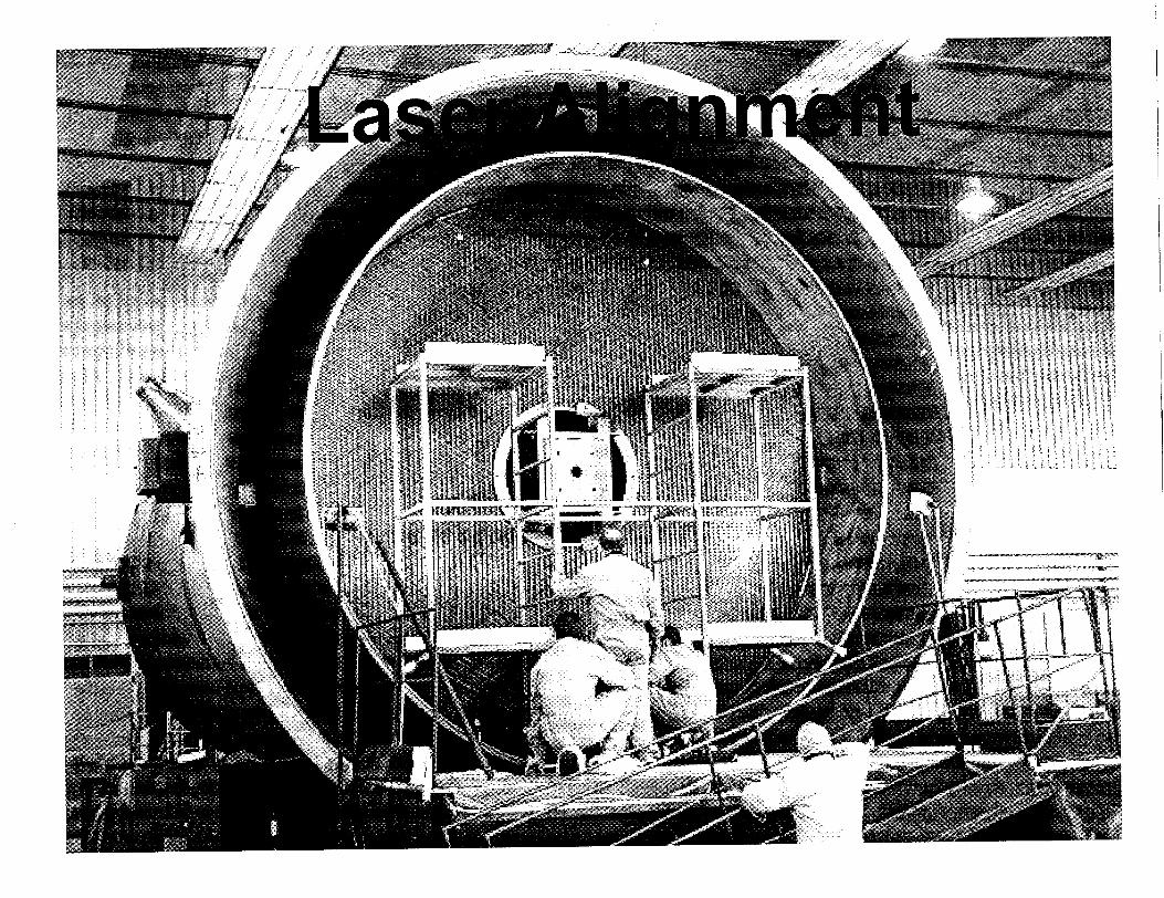
* U2R9 (fall 2000) (Complete) • Laser templating of piping in containment * Design walkdowns in containment
• Polar crane inspections
- No major rework required
* U2C10 (winter 2000 - spring 2002) * Personnel access and north side sally port
ý, I J,/

Installation Activities
* U2R10 (spring 2002) * Remove/relocate interfering commodities from
bioshield wall • Polar crane preparations (based on U2R9
inspection)
* SG2 auxiliary crane supports
,V0j

Installation Activities
SU2C11 (summer 2002 - fall 2003) • Craft access facility
* Outside lift system
• Haul route
e RSG preparations
* U2RII (fall 2003) * Bioshield wall modifications
o Replace steam generators
\1ji

YTFAU tiJFlrlDATi'0 OCDI Af"EiUEL a =• LIrl- -.. -I. -1- r.,ml I LJM
I IG REPLACEMENT CONTRACTOR PROCESSING, OFFICE & BREAK AREA FACILITY (EXISTING)
A 81G REPLACEMENT CONTRACTOR WAREHOUSE FACILITY (EXISTING)
5 REPLACEMENT SIG OFFLOADISTORAGE LOCATION
4 CONTAINMENT ACCESS, CRAFT ASSEMBLY AREA & PODIOUTAGE MANAGEMENT FACILITY
S OLD S/G STORAGE LOCATION
SIG CONTRACTOR SECURITY ACCESS FACILITY
EMERGENCY PERSONNEL HATCH)
® FAB SHOP, WELD TEST SHOP & MOCK-UP FACILITY (EXISTING)
LAYDOWN AREA
CONTRACTOR PARKING AREA
DECONTAMINATION FACILITY
May 9,20001. SECURITY GATE TO BE REWORKED
TO FACILITATE SO MOVEMENT INTO PROTECTED AREA.
2. CONTRACTOR TRUCKISMALL EQUIPMENT ACCESS TO PROTECTED AREA
ý' I I/
Licensing Activities
*Submittal is being reviewed by a crossdisciplinary team including members from another utility
* Final safety analysis results are within criteria defined at the outset of the project
ý k I--, /

Licensing Activities
+ APS will provide submittal to NRC in June 2001
* Request approval in June 2002
+ U2C12 fuel design to commence in September 2002 based on SER from NRC
'div
Technical Specification Changes
+ Definition of rated thermal power
* Low SG pressure reactor trip setpoint
* Low SG pressure MSIS setpoint
* Peak containment pressure
* Operating range for cold leg temperature at 100 percent power
* Allowable power vs. operable MSSVs
*\ kI ,
Safety Analyses
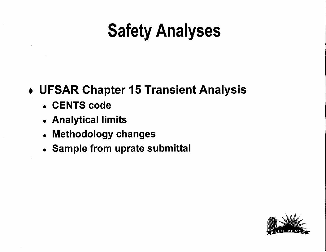
* UFSAR Chapter 15 Transient Analysis • CENTS code * Analytical limits • Methodology changes
• Sample from uprate submittal

Safety Analyses
* CENTS will replace CESEC-III as the primary tool for Chapter 15 non-LOCA transient analysis.
* Implementation of CENTS targeted for Unit 2 Cycle 11 in accordance with GL 83-11 Supplement I guidelines.
+ CENTS will be used to predict global changes in RCS pressure during the CEA ejection event. STRIKIN-II will continue to be used to predict local conditions (i.e. fuel enthalpy and DNBR).
\4j I ,

Safety Analyses
Initial conditions at full power Values Include appropriate uncertainties
Power Inlet temperature Pressurizer pressure RCS mass flow rate Pressurizer level
SG level Axial power distribution
MTC Primary to secondary leakage
= 4070 MWt (3990 + uncertainty) = 548 to 566*F
= 2100 to 2325 psia = 95% to 116% of design = 24% to 59%
= 4% to 92% NR = -0.20 to +0.20 ASI = -0.20 to -4.0 E-4 delta-rho/°F = 720 gpd I SG
,-. ý I "

Safety Analyses SMethodology changes
The following methods/assumptions changes will be applied to both the current plant configuration (Units 1/3) and Unit 2 RSG/uprate
- Dose calculations will assume a decontamination factor of 100 (partition factor of 0.01) for the intact SG
- Post-trip MSLB will employ a more detailed reactivity calculation, including moderator density feedback in the hot channel

Safety Analyses
* Methodology changes (cont.) - Single RCP sheared shaft with LOP will
assume that, at 90 minutes, the operator will re-establish level in the affected SG
- SGTR+LOP will credit EOP-based isolation of affected SG
Safety Analyses
SSample from uprate submittal • Outline and contents of the safety analysis
portion of the submittal is based on a composite of the PVNGS UFSAR and the Farley uprate submittal
Safety Analyses
SSample from uprate submittal (cont.) Inadvertent opening of a SGADV
- Identification of causes and event description
- Acceptance criteria
- Description of analysis
- Input parameters, initial conditions, and assumptions
- Results
- Conclusions

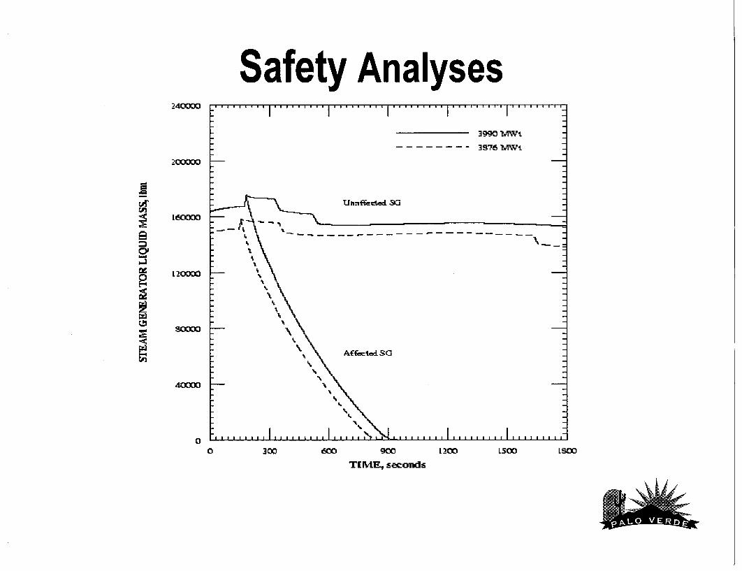
Safety Analyses Table 6.3-8: Sequence of Events for IOSGADV+LOP Event
Time (sec) Event Value
3876 3990 3876 3990 MWt MWt MWt MWt
0.00 0.00 Inadvertent opening of SG#1 ADV ......
0.00 0.00 Hot Channel Minimum DNBR 1.72 1.72
147.9 176.5 SG pressure reaches MSIS/Trip setpoint (psia) 850 915
149.1 177.7 Reactor/Turbine trip ......
Loss of Offsite Power
149.7 178.3 Scram CEAs begin falling ......
151.2 179.7 Minimum DNBR > SAFDL > SAFDL
153.5 182.1 MSIVs Closed ......
352.7 329.3 SG#2 MSSV Bank 1 Open (psia) 1303 1303
Begin Oscillating
463.9 428.3 RCS pressure reaches SIAS setpoint (psia) 1750 1750
919 1005 SG#1 Empties ......
1800 1800 Operators manually close SG#1 ADV ......
1800 1800 Operators initiate cooldown (min) 30 30
\. I ,

Safety Analyses- 3990 SMWt
- -- - - ý - 39.715 - -Lt
L20
T[r4E, seconds
- I - I - I
- I - I - I - I - I - I - I - I - I - I - I - I - I - I - I - I - I
- I - I - I - I
- I - I - I - I
- I'
L 200 1500 LStC
* .1.111.... 11.1....'.'
so
60
40
2 0
-� I I
20
00
\iJI
i . . - - - - . . . . . . . . . . . . . . . . . . . . . . . .
I I I I I
I I
Ow

Safety Analyses 3.10
-- 3990 MWt
2.80 3876 MWt
U
2.50 I
I
S2.20
- 1.90
- I
1.60
1.30
1.00 0 40 80 120 160 200
TIME, sec
ýt t i 'o,
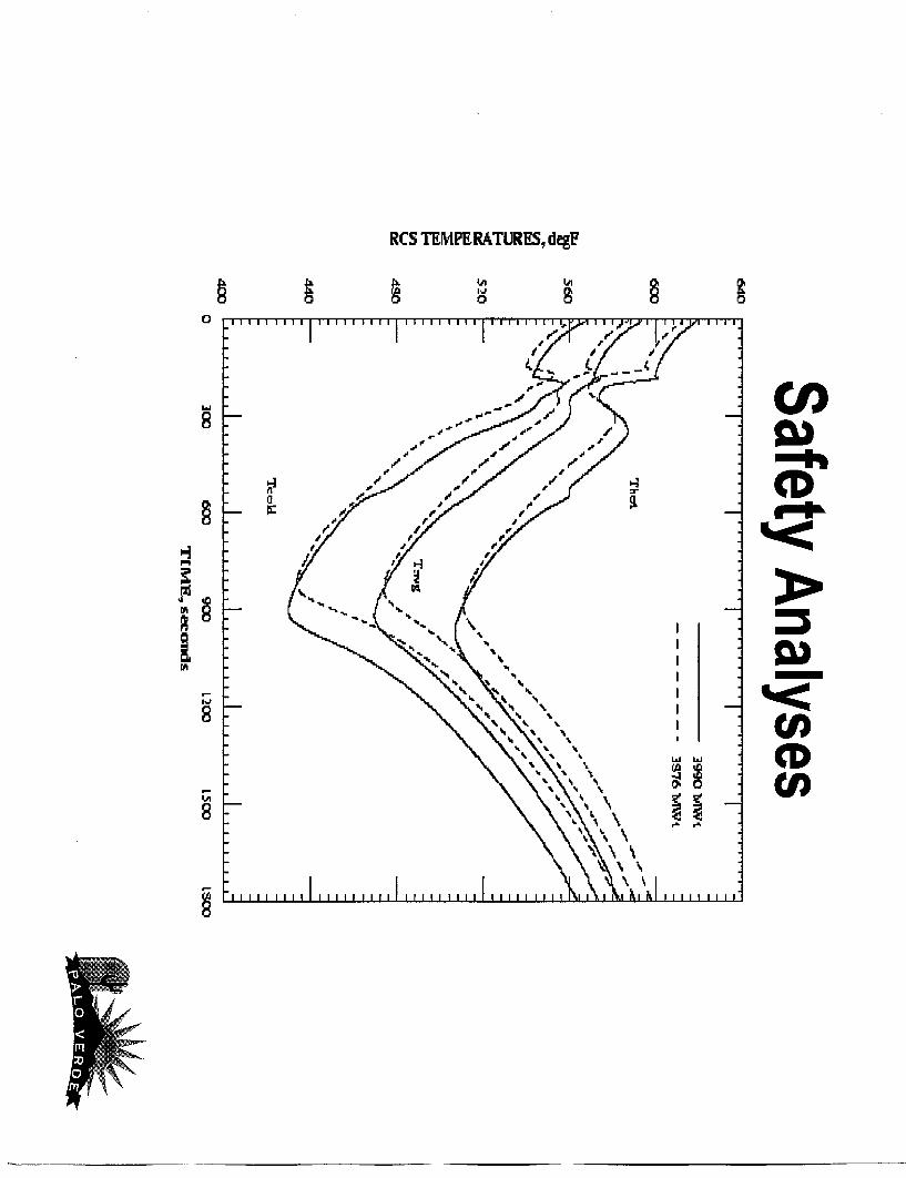
RCS TEMPERATURES., degE
kA L
W In
CI)
Ld WCD

Safety Analyses.. . .. . .. . .. .. .I .. . . .. .
- I - I
- I - I - I - I
- I - I - I - I - I - I - I - I - I - I - I - I
- I - I - I - I- 9' - I - I
3976 IAWi
TKYU L
SCL,±zu
S.,,. SUISISI 55555111515511.1.... ii * a I*l1
SSSIII IS I
300~ 900~ T IPE., s coud s
L 200~
2
0
Sp
-2
4
-6
-S
-LtO
0
v t /

Safety Analyses _2750 . . . . ... . . ..... . . . . . . . . . . . . .1 .. . . . . . . .. I . . . . . . . . .
3990 lX, Wi
- -. . . . . .- .. 38.76 bAWIV L ,.•.." 2500
2250,
L750---------S/
LSOO S
L250 /
L250 . . . . ..l1 , , l 1 I . . . . . . . .. I. . .. . .. . ..
0 300 600O 900 L 200 L500 LSMD
T[ ME, s eonds

Safety Analyses L5.0 ......... .................. ............... ......... ..
Uhmf~ctud Sa
t 250,..,- " 1 p-I
- - 3976 MWtL
750
DI]
500~
250 16
Af.fvtr. dSG C!
0 F ......... I .. . . .I .I .I . . ...... I ........
0 300 60 900 L 200 L500 tLSW
T MIE s onds
Safety Analyses 24C oD . . . .. . . .. . . . . .. . . .. . . . . .. . . .. . . .. . . . I . . . . . . . .. I "T
3990 MW''
- -- - - - - - 3S76 MW-V'
200•00
L -----
-\ . . . . . . .----- -------\
L~IL
0 300 1200 LSOO
T[E MIE., seconds
0//

Safety Analyses
SSample from uprate submittal (cont.) Conclusion
For the IOSGADV+LOP event, all of the acceptance criteria are met. The peak primary and secondary pressures remain below 110 percent of design at all times, thus ensuring the integrity of the RCS and main steam systems. The minimum hot channel DNBR remains above the SAFDL, thus ensuring fuel cladding integrity. Offsite radiological consequences remain within a small fraction of 10 CFR 100 guidelines.
Risk Evaluation
* Submittal will not be made as a risk
informed licensing amendment
* Power uprate is not large and no substantial change in risk expected
* PRA will be updated to reflect changes due to uprate
-. 0

Control Room Habitability
* Revise design/licensing basis for allowable unfiltered in-leakage
+ Validate allowable in-leakage with baseline testing
+ Expect good results from testing due to CR ventilation system design and previous pressure testing
+ PVNGS will have contingency plan ready if test results are unsatisfactory
Required Plant Modifications
SSpray pond temperature monitoring equipment
SRemove containment spray flow orifices and install Annubar flow elements
SChange steam admission to HP turbine from partial arc to full arc
UI
RCS Piping Weld Issue
SPVNGS has reviewed construction records for RCS welds
* Records recovered to date indicate that welds were completed according to procedure
* Structural analysis for the RCS reflects those procedures
Future Activities
* RSG will be moved from Milan to Montfalcone for final welding later this year
* Meeting to discuss power uprate submittal a few weeks after receipt by NRC
* Point of contact for questions on submittal

PVNGS Unit 2 Steam Generator Replacement Project Integrated Level One Schedule for RSG & Power Up
119991997 18 192000 2001 2002_ 2003 12004MARO
Design & Document Phase
100W
Uprate 8a y 4/98 ame8
U2IA0
Falication of RSG's/Ansaldo Enerma smva. In Miln. Italy
Award Eng. Conýtrat/Obtain Infrastructure Pem*s
Finalize Transportatn Route Intervention Modiicalon
APS & CE RSO I Uprale ,Enneering Analysis
Complete NAC qnginering ~uMl
Transport to Shippng Port
Transport to PVNGS
RSG's Arrive At PVNGS #9102
9196 2101 � 9/ni
NRCeEvaluation o of S ittal
%SG& Power Upralie Modiiato EnglnerWng& InstallationIMS 12W0
cs rfif.acmtUprat.Mod Eng 2dJ0 1 7/01
Spray Pond Temp Transmitter Uprate Mod Eng
1/01ttJl•
Signed Installation Phase I Contract With Bechtel
3/99 ii!
CS orifie pe~apmment Uprate Mod Installation 30 5=V02MM 9 5 1203
SP Temp Transmitter Uprate Mod Instalation
Main Transformer Cooling Eng. Main Transformer Cooling Installation 1/0 t Ol M O 601 3WC2 102.. :: Coollng Tower Wind Vane Eng. M 1/0 :12/01,o+ :: MT Throttle Valve
Cooling Tower Wind Vane Installation MT Thottle Valve Mod Eng. Mod Installation 1/02. 51•029/ 2 1/030
Site Preparations for Installation" 9 12103
U2R8 -Laser Piping Templating .4 ::5 9
U2R9 - Design Verification Walkdowns U2R10 - BlO.11ield Wall Mods l9/o0 m11/O0 3 002
Prepare/issue U2R1O DCP's Prepare/issue U2R10 WP's SG Level Transmitter Installation
SG Level Transmltter Design Eng SG Level Transmitter Installation VW-0 MUOMM11101 3weno 5"0
Prepare/issue Const Proc.
2101 8A)1•o MW =, Install Protected Ama Access - North
U2R1 1 - Replace SG's 103 2/O03I
Prepare/issue U2R11 WP's W02 6W3
S1/01 2/0 Prepare/issue U2RI 1 DCP:s
Design/Construct 080 Storage/NSG Storage Facilities
North Anex Remodeling Install Downcomner Blowdown Electrical Modification S101 12 01. . _ 11flg
Contract Awarded To Ansetdo
12/07
u2RtI