tester, diesel injector nozzle model dt … diesel injector nozzle model dt-1300/7008 (kiene diesel...
TRANSCRIPT
T M 9 - 4 9 1 0 - 6 2 3 - 1 4 & P
TECHNICAL MANUAL
OPERATOR’S ORGANIZATIONAL, DIRECT SUPPORTAND GENERAL SUPPORT MAINTENANCE MANUAL
INCLUDING REPAIR PARTS LIST
TESTER, DIESEL INJECTOR NOZZLEM O D E L D T - 1 3 0 0 / 7 0 0 8
(KIENE DIESEL ACCESSORIES, INC.)( N S N 4 9 1 0 - 0 0 - 2 5 5 - 8 6 4 1 )
H E A D Q U A R T E R S , D E P A R T M E N T O F T H E A R M Y

TM 9-4910-623-14&PC1
HEADQUARTERSDepartment of the Army
Washington D. C., 5 September 1995ChangeNo. 1
OPERATORS, ORGANIZATIONAL, DIRECT SUPPORTAND GENERAL SUPPORT MAINTENANCE MANUAL
INCLUDING REPAIR PARTS LISTFOR
TESTER, DIESEL INJECTOR NOZZLEMODEL DT-1300/7008
(KIENE DIESEL ACCESSORIES, INC.)(NSN 4910-O0-255-8641)
TM 9-4910–623-14&P, dated 15 May 1980 is changed as follows:
1. Remove old pages and insert new pages as indicated below.
2. New or changed material is indicated by a vertical bar in the margin of the page. Illustration changesare indicated by a pointing hand adjacent to the illustrations.
Remove Pages Insert Pagesi and ii i and ii1 and 2 1 and 29 thru 15 9 thru 13
3. File this change sheet in back of the publication for reference purposes.
Change 1
By Order of the Secretary of the Army:
DENNIS J. REIMERGeneral, United States Army
Chief of Staff
Official:
Acting Administrative Assistant to theSecretary of the Army
0 0 6 5 8
DISTRIBUTION: To be distributed in accordance with DA Form 12-25-E, block 4942requirements for TM 9–4910–623–14&P.
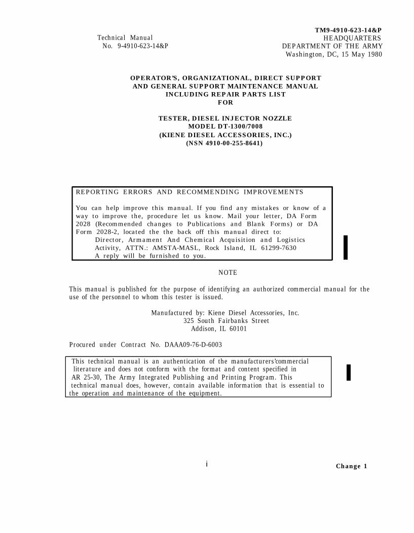
TM9-4910-623-14&PTechnical Manual HEADQUARTERS
No. 9-4910-623-14&P DEPARTMENT OF THE ARMYWashington, DC, 15 May 1980
OPERATOR’S, ORGANIZATIONAL, DIRECT SUPPORTAND GENERAL SUPPORT MAINTENANCE MANUAL
INCLUDING REPAIR PARTS LISTFOR
TESTER, DIESEL INJECTOR NOZZLEMODEL DT-1300/7008
(KIENE DIESEL ACCESSORIES, INC.)(NSN 4910-00-255-8641)
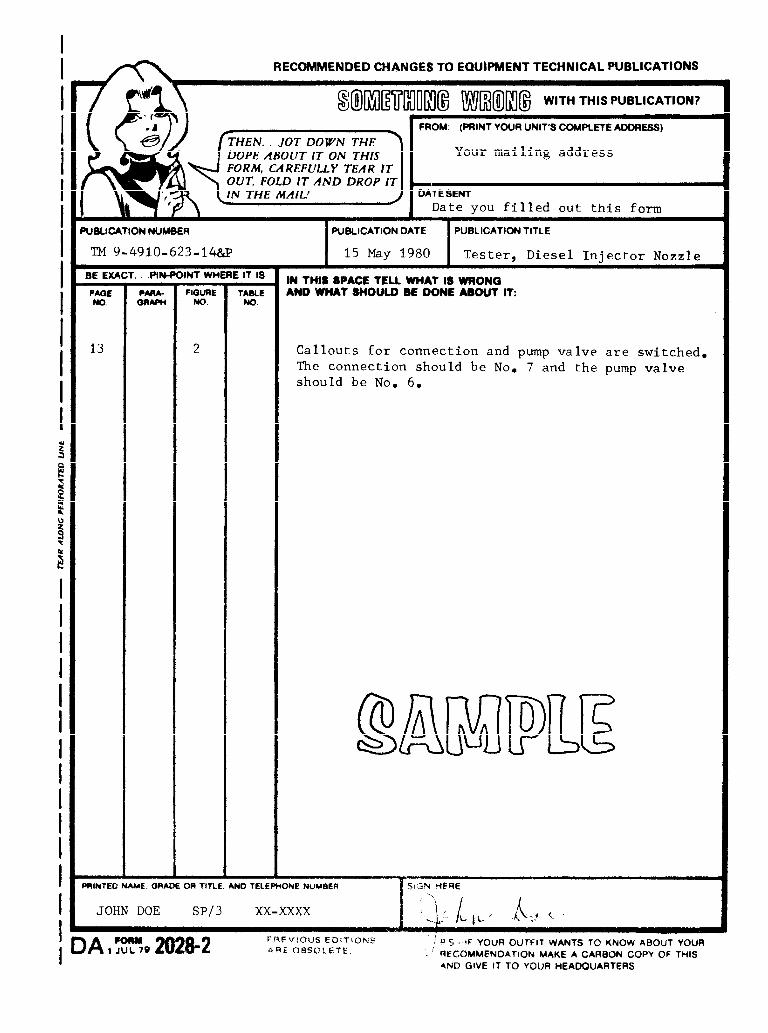
REPORTING ERRORS AND RECOMMENDING IMPROVEMENTS
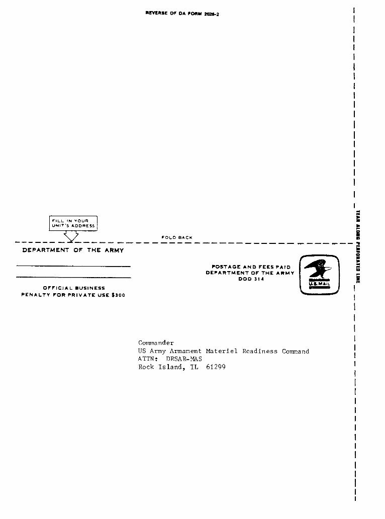
You can help improve this manual. If you find any mistakes or know of away to improve the, procedure let us know. Mail your letter, DA Form2028 (Recommended changes to Publications and Blank Forms) or DAForm 2028-2, located the the back off this manual direct to:
Director, Armament And Chemical Acquisition and LogisticsActivity, ATTN.: AMSTA-MASL, Rock Island, IL 61299-7630A reply will be furnished to you.
NOTE
This manual is published for the purpose of identifying an authorized commercial manual for theuse of the personnel to whom this tester is issued.
Manufactured by: Kiene Diesel Accessories, Inc.325 South Fairbanks Street
Addison, IL 60101
Procured under Contract No. DAAA09-76-D-6003
This technical manual is an authentication of the manufacturers’commercialliterature and does not conform with the format and content specified in
AR 25-30, The Army Integrated Publishing and Printing Program. Thistechnical manual does, however, contain available information that is essential to
the operation and maintenance of the equipment.
i Change 1
TM 9-4910-623-14&P
Section I
II
III.
IV
V
12
Change 1
INTRODUCTION AND DESCRIPTIONIntroductionPurposeDescriptionIdentification of components and accessoriesPREPARATION FOR USE AND TRANSPORTINGPreparation for useTransportingOPERATING CONTROLS AND COMPONENTSOperating controlsMeasuring devices and other componentsTESTINGGeneral procedures for testing fuel injector nozzlesGeneral procedures for leakage testMAINTENANCEReplacement of pressure gageReplacement of filterLubricationTroubleshootingPARTS LISTParts List
ii
Paragraph
1234
56
78
10
11121314
Page
1111
44
46
69
9111212
10
TM 9-4910-623-14 & P
INSTRUCTIONS FOR REQUISITIONING PARTS
NOT IDENTIFIED BY NSN
When requisitioning parts not identified by National Stock Number, it ismandatory that the following information be furnished the supply officer.
1 -
2 -
3 -
4 -
5 -
6 -
7 -
Manufacturer's Federal Supply Code Number - 33559
Manufacturer’s Part Number exactly as listed herein.
Nomenclature exactly as listed herein, including dimensions, ifnecessary.
Manufacturer’s Model Number - Model DT-1300/7008
Manufacturer's Serial Number (End Item)
Any other information such as Type, Frame Number, and ElectricalCharacteristics, if applicable.
If DD Form 1348 is used, fill in all blocks except 4, 5, 6, andRemarks field in accordance with AR 725-50.
Complete Form as Follows:
(a) In blocks 4, 5, 6, list manufacturer’s Federal Supply CodeNumber - 33559 followed by a colon and manufacturer’sPart Number for the repair part.
(b) Complete Remarks field as follows:Noun : (nomenclature of repair part)For: NSN : 4910-00-255-8641Manufacturer: Kiene Diesel Accessories, Inc.
Model: DT-1300/7008Serial: (of end item)
Any other pertinent information such as Frame Number,Type, Dimensions, etc.
iii

TM 9-4910-623-14&P
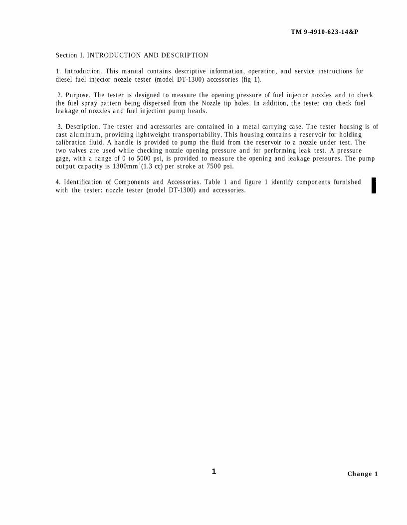
Section I. INTRODUCTION AND DESCRIPTION
1. Introduction. This manual contains descriptive information, operation, and service instructions fordiesel fuel injector nozzle tester (model DT-1300) accessories (fig 1).
2. Purpose. The tester is designed to measure the opening pressure of fuel injector nozzles and to checkthe fuel spray pattern being dispersed from the Nozzle tip holes. In addition, the tester can check fuelleakage of nozzles and fuel injection pump heads.
3. Description. The tester and accessories are contained in a metal carrying case. The tester housing is ofcast aluminum, providing lightweight transportability. This housing contains a reservoir for holdingcalibration fluid. A handle is provided to pump the fluid from the reservoir to a nozzle under test. Thetwo valves are used while checking nozzle opening pressure and for performing leak test. A pressuregage, with a range of 0 to 5000 psi, is provided to measure the opening and leakage pressures. The pumpoutput capacity is 1300mm3 (1.3 cc) per stroke at 7500 psi.
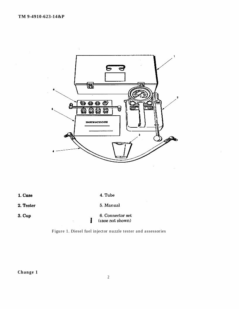
4. Identification of Components and Accessories. Table 1 and figure 1 identify components furnishedwith the tester: nozzle tester (model DT-1300) and accessories.
1 Change 1
TM 9-4910-623-14&P
Figure 1. Diesel fuel injector nuzzle tester and assessories
Change 12
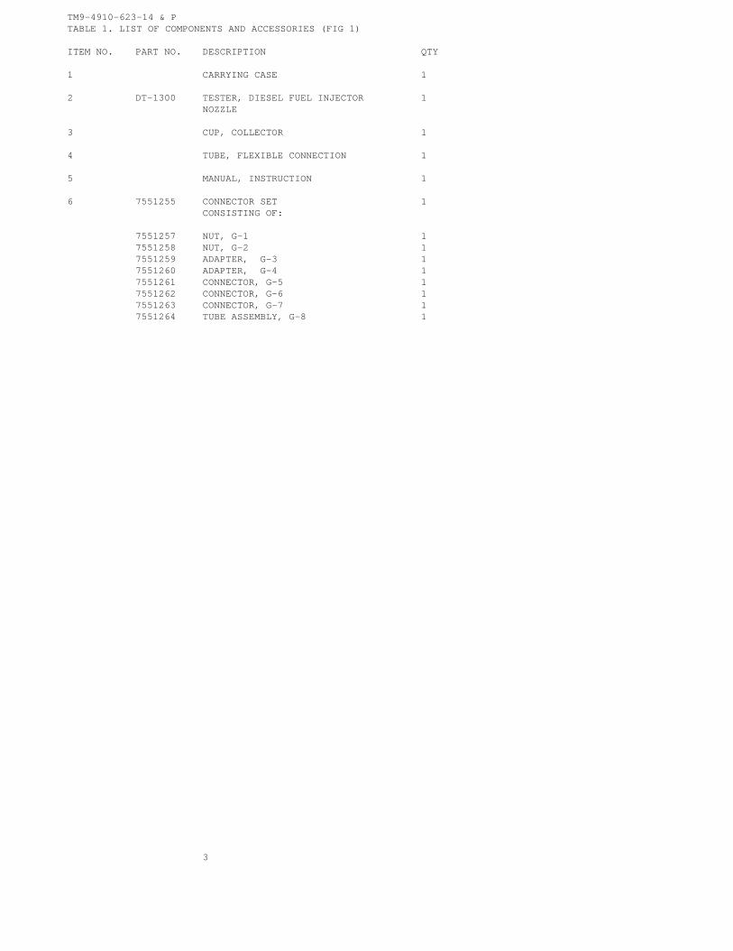
TM9-4910-623-14 & PTABLE 1. LIST OF COMPONENTS AND ACCESSORIES (FIG 1)
ITEM NO. PART NO. DESCRIPTION QTY
1 CARRYING CASE 1
2 DT-1300 TESTER, DIESEL FUEL INJECTOR 1NOZZLE
3 CUP, COLLECTOR 1
4 TUBE, FLEXIBLE CONNECTION 1
5 MANUAL, INSTRUCTION 1
6 7551255 CONNECTOR SET 1CONSISTING OF:
7551257 NUT, G-1 17551258 NUT, G-2 17551259 ADAPTER, G-3 17551260 ADAPTER, G-4 17551261 CONNECTOR, G-5 17551262 CONNECTOR, G-6 17551263 CONNECTOR, G-7 17551264 TUBE ASSEMBLY, G-8 1
3
TM 9-4910-623-14 & PSection II. PREPARATION FOR USE AND TRANSPORTING
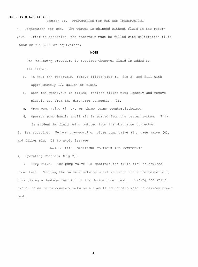
5. Preparation for Use. The tester is shipped without fluid in the reser-
voir. Prior to operation, the reservoir must be filled with calibration fluid
6850-00-974-3738 or equivalent.
a.
b.
c.
d.
The following
the tester.
To fill the
NOTE
procedure is required whenever fluid is added to
reservoir, remove filler plug (1, fig 2) and fill with
approximately 1/2 gallon of fluid.
Once the reservoir is filled, replace filler plug loosely and remove
plastic cap from the discharge connection (2).
Open pump valve (3)
Operate pump handle
is evident by fluid
two or three turns counterclockwise.
until air is purged from the tester system. This
being omitted from the discharge connector.
6. Transporting. Before transporting,
and filler plug (1) to avoid leakage.
Section III. OPERATING
7. Operating Controls (Fig 2).
close pump valve (3), gage valve (4),
CONTROLS AND COMPONENTS
a. Pump Valve. The pump valve (3) controls the fluid flow to devices
under test. Turning the valve clockwise until it seats shuts the tester off,
thus giving a leakage reaction of the device under test. Turning the valve
two or three turns counterclockwise allows fluid to be pumped to devices under
test.
4
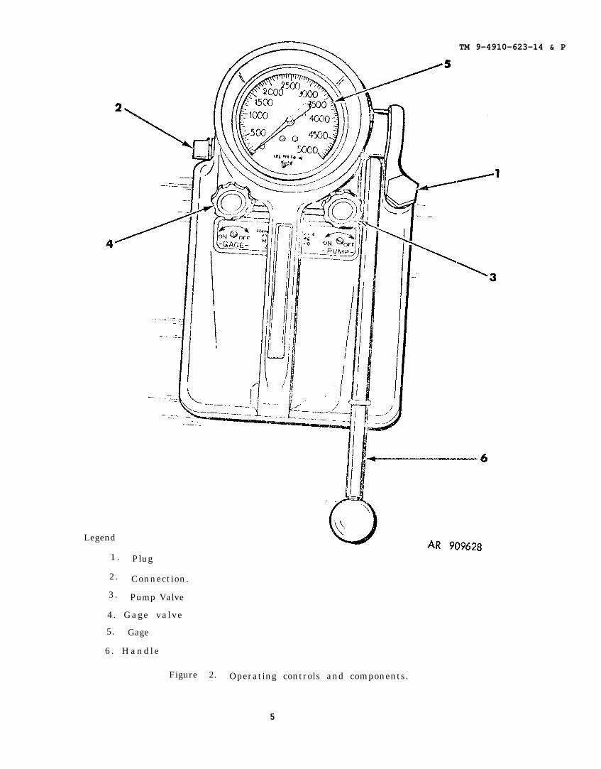
Legend
TM 9-4910-623-14 & P
1 . Plug
2. Connection.
3. Pump Valve
4. Gage valve
5. Gage
6 . Handle
Figure 2. Operating controls and components.
5
TM 9-491O-623-14&P
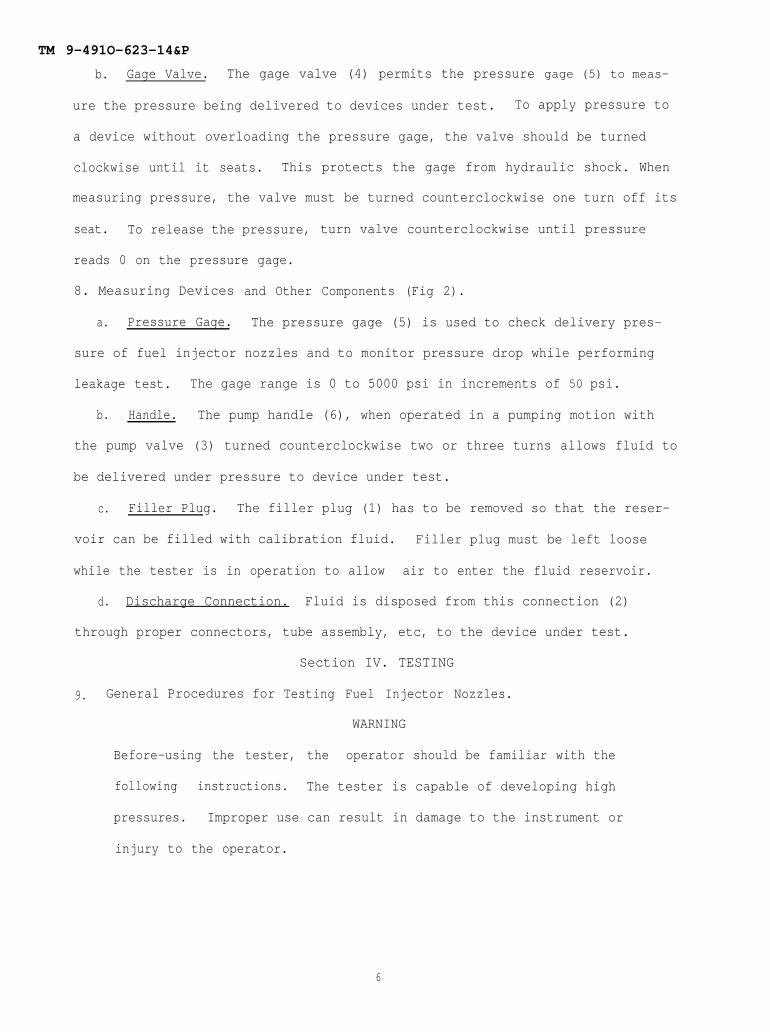
b. Gage Valve. The gage valve (4) permits the pressure gage (5) to meas-
ure the pressure being delivered to devices under test. To apply pressure to
a device without overloading the pressure gage, the valve should be turned
clockwise until it seats. This protects the gage from hydraulic shock. When
measuring pressure, the valve must be turned counterclockwise one turn off its
seat. To release the pressure, turn valve counterclockwise until pressure
reads 0 on the pressure gage.
8. Measuring Devices and Other Components (Fig 2).
a. Pressure Gage. The pressure gage (5) is used to check delivery pres-
sure of fuel injector nozzles and to monitor pressure drop while performing
leakage test. The gage range is 0 to 5000 psi in increments of 50 psi.
b. Handle. The pump handle (6), when operated in a pumping motion with
the pump valve (3) turned counterclockwise two or three turns allows fluid to
be delivered under pressure to device under test.
c. Filler Plug. The filler plug (1) has to be removed so that the reser-
voir can be filled with calibration fluid. Filler plug must be left loose
while the tester is in operation to allow air to enter the fluid reservoir.
d. Discharge Connection. Fluid is disposed from this connection (2)
through proper connectors, tube assembly, etc, to the device under test.
Section IV. TESTING
9. General Procedures for Testing Fuel Injector Nozzles.
WARNING
Before-using the tester, the operator should be familiar with the
following instructions. The tester is capable of developing high
pressures. Improper use can result in damage to the instrument or
injury to the operator.
6
7
TM 9-4910-623-14 & P
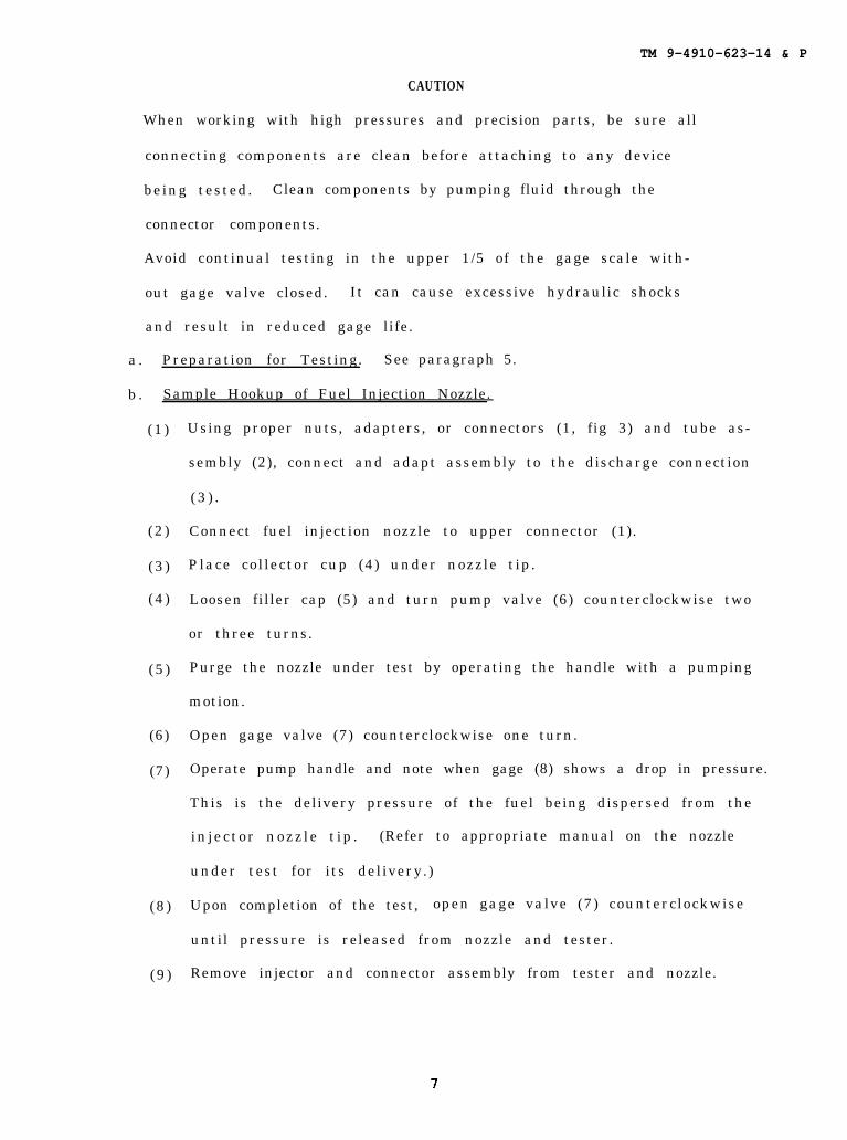
CAUTION
When working with high pressures and precision parts, be sure all
connecting components are clean before attaching to any device
being tested. Clean components by pumping fluid through the
connector components.
Avoid continual testing in the upper 1/5 of the gage scale with-
out gage valve closed. It can cause excessive hydraulic shocks
and result in reduced gage life.
a . Preparation for Testing. See paragraph 5.
b . Sample Hookup of Fuel Injection Nozzle.
(1 )
(2 )
(3 )
(4 )
(5 )
(6)
(7)
(8 )
(9 )
Using proper nuts, adapters, or connectors (1, fig 3) and tube as-
sembly (2), connect and adapt assembly to the discharge connection
( 3 ) .
Connect fuel injection nozzle to upper connector (1).
Place collector cup (4) under nozzle tip.
Loosen filler cap (5) and turn pump valve (6) counterclockwise two
or three turns.
Purge the nozzle under test by operating the handle with a pumping
motion.
Open gage valve (7) counterclockwise one turn.
Operate pump handle and note when gage (8) shows a drop in pressure.
This is the delivery pressure of the fuel being dispersed from the
in jec tor nozz le t ip . (Refer to appropriate manual on the nozzle
under test for its delivery.)
Upon completion of the test, open gage valve (7) counterclockwise
until pressure is released from nozzle and tester.
Remove injector and connector assembly from tester and nozzle.
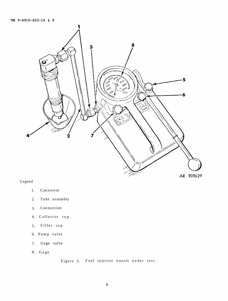
TM 9-4910-623-14 & P
Legend
1 . Connector
2. Tube assembly
3. Connection
4 . Col lec tor cup
5. Fi l ler cap
6. Pump valve
7. Gage valve
8 . Gage
Figure 3. Fuel injector nozzle under test.
8
TM 9-4910-623-14 & P
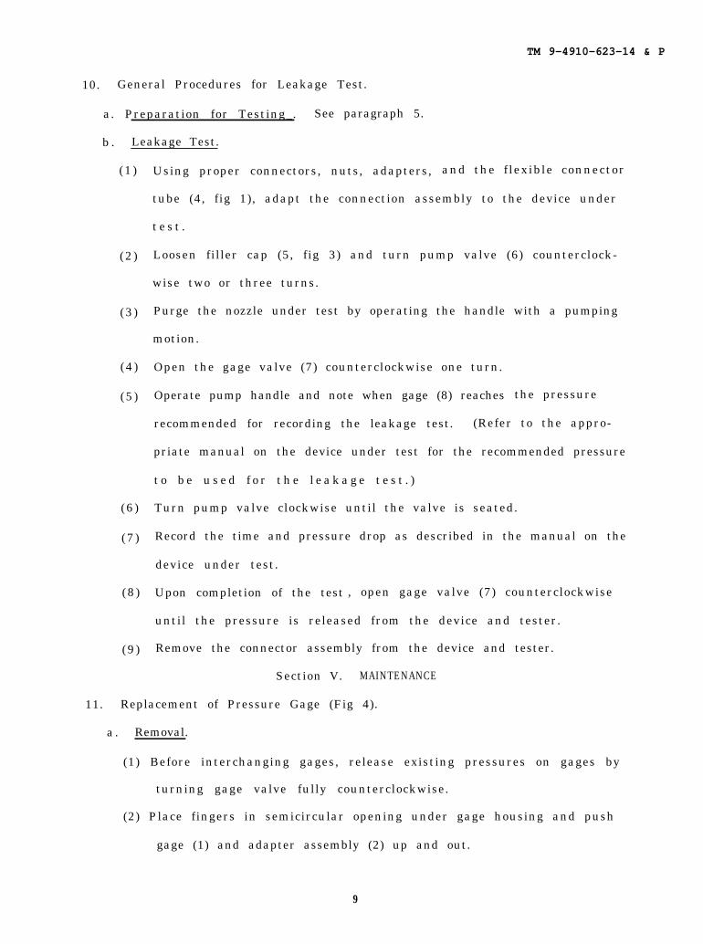
10. General Procedures for Leakage Test.
a. Preparation for Testing_. See paragraph 5.
b . Leakage Test.
(1 )
(2 )
(3 )
(4 )
(5 )
(6 )
(7 )
(8 )
(9 )
Using proper connectors, nuts, adapters, and the f lexible connector
tube (4, fig 1), adapt the connection assembly to the device under
t e s t .
Loosen filler cap (5, fig 3) and turn pump valve (6) counterclock-
wise two or three turns.
Purge the nozzle under test by operating the handle with a pumping
motion.
Open the gage valve (7) counterclockwise one turn.
Operate pump handle and note when gage (8) reaches the pressure
recommended for recording the leakage test. (Refer to the appro-
priate manual on the device under test for the recommended pressure
t o b e u s e d f o r t h e l e a k a g e t e s t . )
Turn pump valve clockwise until the valve is seated.
Record the time and pressure drop as described in the manual on the
device under test.
Upon completion of the test , open gage valve (7) counterclockwise
until the pressure is released from the device and tester.
Remove the connector assembly from the device and tester.
Section V. MAINTENANCE
11. Replacement of Pressure Gage (Fig 4).
a . Removal.
(1) Before interchanging gages, release existing pressures on gages by
turning gage valve fully counterclockwise.
(2) Place fingers in semicircular opening under gage housing and push
gage (1) and adapter assembly (2) up and out.
9
TM 9-4910-623-14&P
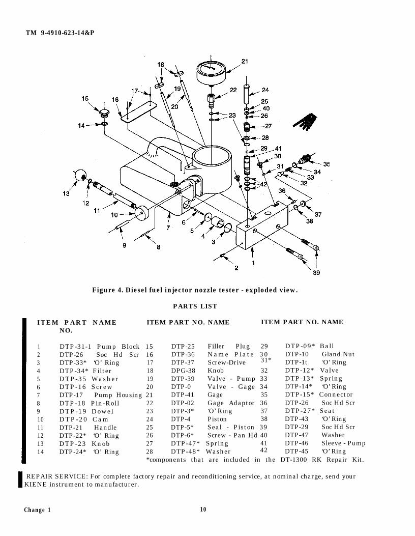
Figure 4. Diesel fuel injector nozzle tester - exploded view.
PARTS LIST
ITEM PART NAME ITEM PART NO. NAME ITEM PART NO. NAMENO.
1234567891011121314
DTP-31-1 Pump Block 15 DTP-25 Filler Plug 29 DTP-09* BallDTP-26 Soc Hd Scr 16 DTP-36 Name Plate 30 DTP-10 Gland NutDTP-33* ‘O’ Ring 17 DTP-37 Screw-Drive 31* DTP-1t ‘O’ RingDTP-34* Filter 18 DPG-38 Knob 32 DTP-12* ValveDTP-35 Washer 19 DTP-39 Valve - Pump 33 DTP-13* SpringDTP-16 Screw 20 DTP-0 Valve - Gage 34 DTP-14* ‘O’ RingDTP-17 Pump Housing 21 DTP-41 Gage 35 DTP-15* ConnectorDTP-18 Pin-Roll 22 DTP-02 Gage Adaptor 36 DTP-26 Soc Hd ScrDTP-19 Dowel 23 DTP-3* ‘O’ Ring 37 DTP-27* SeatDTP-20 Cam 24 DTP-4 Piston 38 DTP-43 ‘O’ RingDTP-21 Handle 25 DTP-5* Seal - Piston 39 DTP-29 Soc Hd ScrDTP-22* ‘O’ Ring 26 DTP-6* Screw - Pan Hd 40 DTP-47 WasherDTP-23 Knob 27 DTP-47* Spring 41 DTP-46 Sleeve - PumpDTP-24* ‘O’ Ring 28 DTP-48* Washer 42 DTP-45 ‘O’ Ring
*components that are included in the DT-1300 RK Repair Kit.
REPAIR SERVICE: For complete factory repair and reconditioning service, at nominal charge, send yourKIENE instrument to manufacturer.
Change 1 10
TM 9-4910-623-14&P
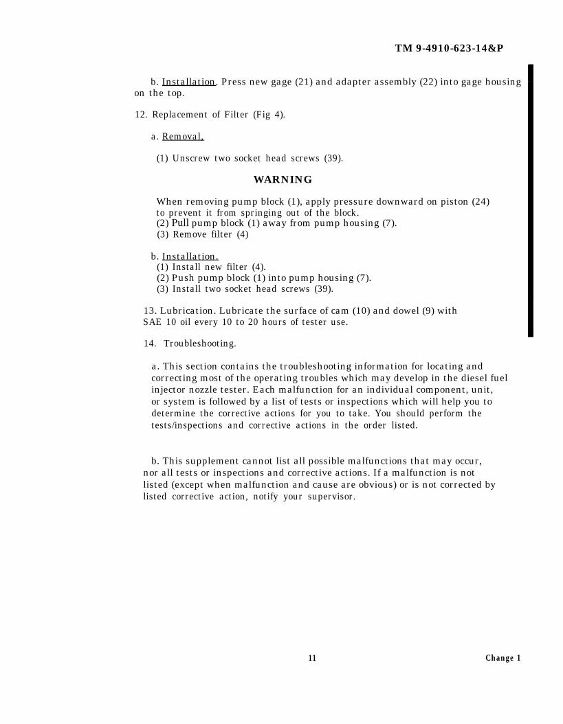
b. Installation. Press new gage (21) and adapter assembly (22) into gage housingon the top.
12. Replacement of Filter (Fig 4).
a. Removal,
(1) Unscrew two socket head screws (39).
WARNING
When removing pump block (1), apply pressure downward on piston (24)to prevent it from springing out of the block.(2) Pull pump block (1) away from pump housing (7).(3) Remove filter (4)
b. Installation.(1) Install new filter (4).(2) Push pump block (1) into pump housing (7).(3) Install two socket head screws (39).
13. Lubrication. Lubricate the surface of cam (10) and dowel (9) withSAE 10 oil every 10 to 20 hours of tester use.
14. Troubleshooting.
a. This section contains the troubleshooting information for locating andcorrecting most of the operating troubles which may develop in the diesel fuelinjector nozzle tester. Each malfunction for an individual component, unit,or system is followed by a list of tests or inspections which will help you todetermine the corrective actions for you to take. You should perform thetests/inspections and corrective actions in the order listed.
b. This supplement cannot list all possible malfunctions that may occur,nor all tests or inspections and corrective actions. If a malfunction is notlisted (except when malfunction and cause are obvious) or is not corrected bylisted corrective action, notify your supervisor.
11 Change 1
TM 9-4910-623-14&P
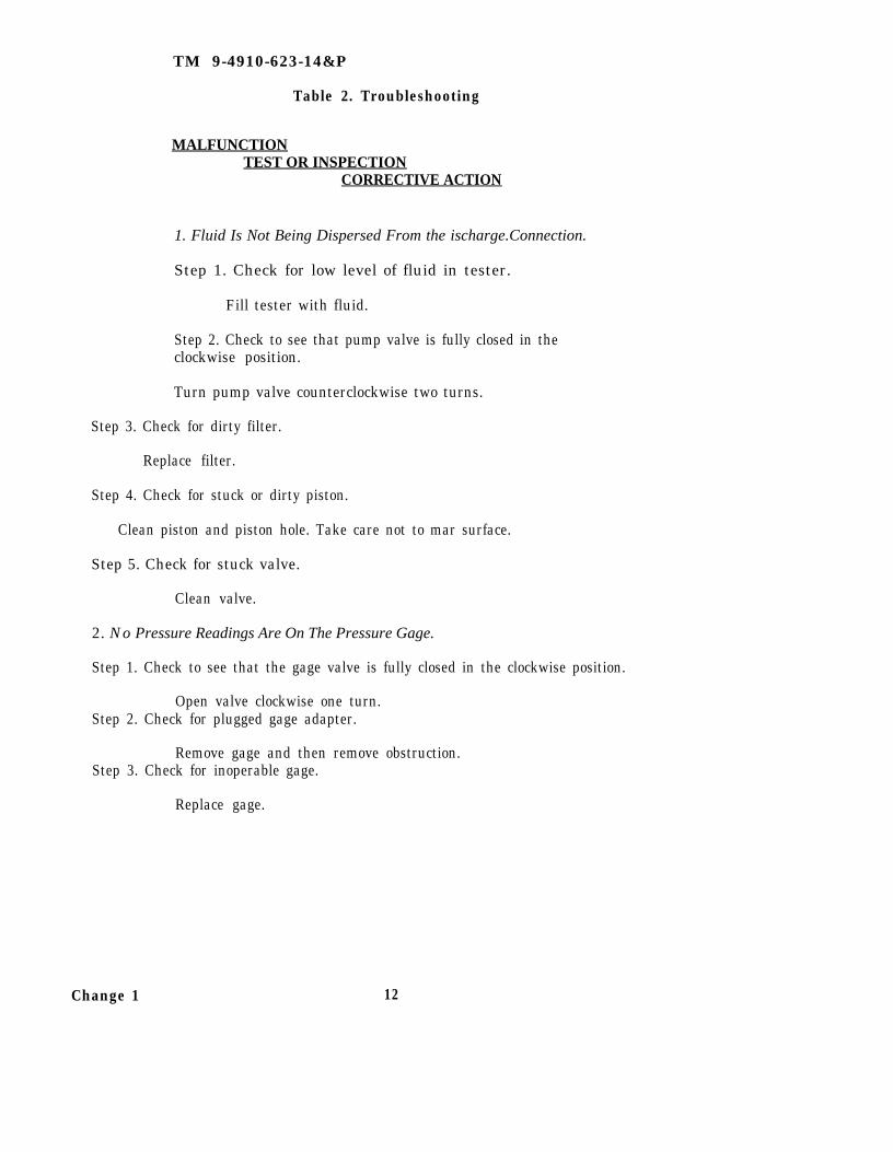
Table 2. Troubleshooting
MALFUNCTIONTEST OR INSPECTION
CORRECTIVE ACTION
1. Fluid Is Not Being Dispersed From the ischarge.Connection.
Step 1. Check for low level of fluid in tester.
Fill tester with fluid.
Step 2. Check to see that pump valve is fully closed in theclockwise position.
Turn pump valve counterclockwise two turns.
Step 3. Check for dirty filter.
Replace filter.
Step 4. Check for stuck or dirty piston.
Clean piston and piston hole. Take care not to mar surface.
Step 5. Check for stuck valve.
Clean valve.
2. No Pressure Readings Are On The Pressure Gage.
Step 1. Check to see that the gage valve is fully closed in the clockwise position.
Open valve clockwise one turn.Step 2. Check for plugged gage adapter.
Remove gage and then remove obstruction.Step 3. Check for inoperable gage.
Replace gage.
Change 1 12
TM 9-4910-623-14&P
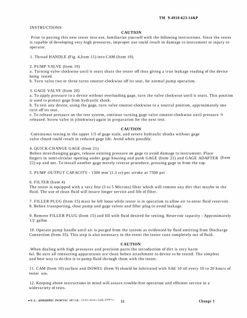
INSTRUCTIONSCAUTION
Prior to putting this new tester into use, familiarize yourself with the following instructions. Since the testeris capable of developing very high pressures, improper use could result in damage to instrument or injury tooperator.
1. Thread HANDLE (Fig. 4,Item 11) into CAM (Item 10).
2. PUMP VALVE (Item 19)a. Turning valve clockwise until it seats shuts the tester off thus giving a true leakage reading of the devicebeing tested.b. Turn valve two or three turns counter-clockwise off its seat, for normal pump operation.
3. GAGE VALVE (Item 20)a. To apply pressure to a device without overloading gage, turn the valve clockwise until it seats. This positionis used to protect gage from hydraulic shock.b. To test any device, using the gage, turn valve counter-clockwise to a neutral position, approximately oneturn off its seat.c. To release pressure on the test system, continue turning gage valve counter-clockwise until pressurereleased. Screw valve in (clockwise) again in preparation for the next test.
CAUTIONContinuous testing in the upper 1/5 of gage scale, and severe hydraulic shocks without gage
valve closed could result in reduced gage life. Avoid when possible.
4. QUICK-CHANGE GAGE (Item 21)Before interchanging gages, release existing pressure on gage to avoid damage to instrument. Placefingers in semi-circular opening under gage housing and push GAGE (Item 21) and GAGE ADAPTER22) up and out. To install another gage merely reverse procedure, pressing gage in from the top.
5. PUMP OUTPUT CAPACITY - 1300 mm3 (1.3 cc) per stroke at 7500 psi
is
(Item
6. FILTER (Item 4)The tester is equipped with a very fine (3 to 5 Microns) filter which will remove any dirt that maybe in thefluid. The use of clean fluid will insure longer service and life of filter.
7. FILLER PLUG (Item 15) must be left loose while tester is in operation to allow air to enter fluid reservoir.8. Before transporting, close pump and gage valves and filler plug to avoid leakage.
9. Remove FILLER PLUG (Item 15) and fill with fluid desired for testing. Reservoir capacity - Approximately1/2 gallon
10. Operate pump handle until air is purged from the system as evidenced by fluid emitting from DischargeConnection (Item 35). This step is also necessary in the event the tester runs completely out of fluid.
CAUTIONWhen dealing with high pressures and precision parts the introduction of dirt is very harm
ful. Be sure all connecting apparatuses are clean before attachment to device to be tested. The simplestand best way to do this is to pump fluid through them with the tester.
11. CAM (Item 10) surface and DOWEL (Item 9) should be lubricated with SAE 10 oil every 10 to 20 hours oftester use.
12. Keeping above instructions in mind will assure trouble-free operation and efficient service in awidevariety of tests.
13 Change 1

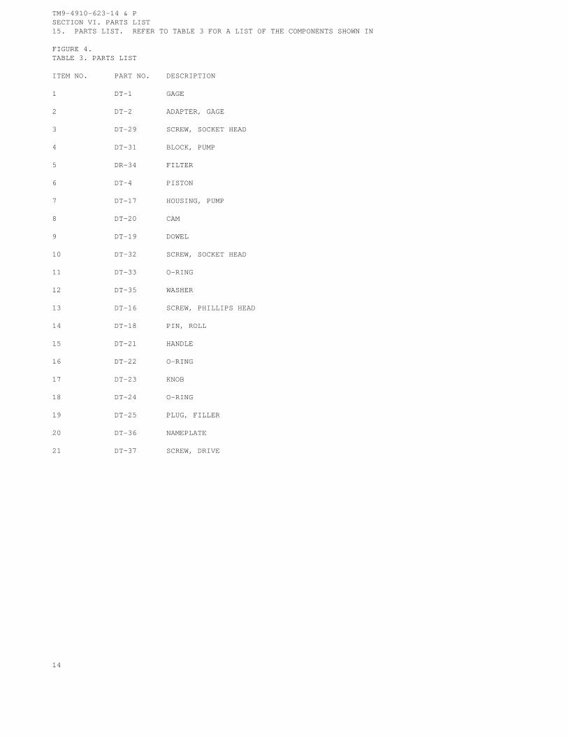
TM9-4910-623-14 & PSECTION VI. PARTS LIST15. PARTS LIST. REFER TO TABLE 3 FOR A LIST OF THE COMPONENTS SHOWN IN
FIGURE 4.TABLE 3. PARTS LIST
ITEM NO. PART NO. DESCRIPTION
1 DT-1 GAGE
2 DT-2 ADAPTER, GAGE
3 DT-29 SCREW, SOCKET HEAD
4 DT-31 BLOCK, PUMP
5 DR-34 FILTER
6 DT-4 PISTON
7 DT-17 HOUSING, PUMP
8 DT-20 CAM
9 DT-19 DOWEL
10 DT-32 SCREW, SOCKET HEAD
11 DT-33 O-RING
12 DT-35 WASHER
13 DT-16 SCREW, PHILLIPS HEAD
14 DT-18 PIN, ROLL
15 DT-21 HANDLE
16 DT-22 O-RING
17 DT-23 KNOB
18 DT-24 O-RING
19 DT-25 PLUG, FILLER
20 DT-36 NAMEPLATE
21 DT-37 SCREW, DRIVE
14
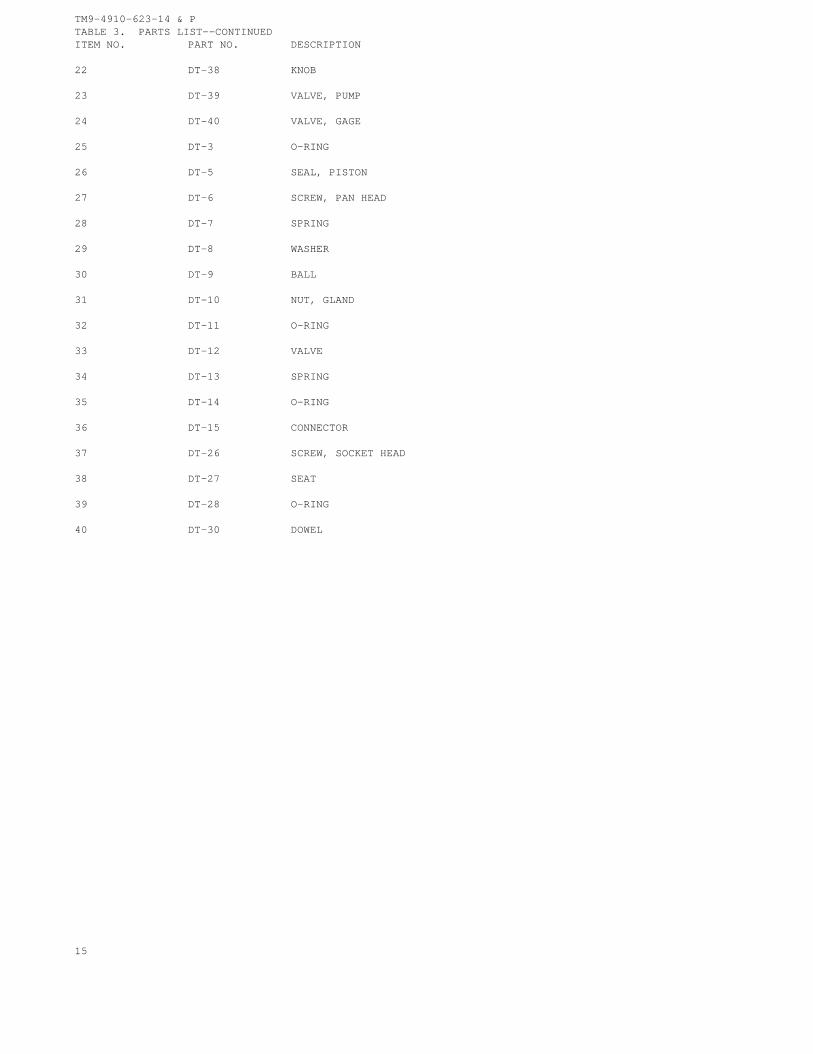
TM9-4910-623-14 & PTABLE 3. PARTS LIST--CONTINUEDITEM NO. PART NO. DESCRIPTION
22 DT-38 KNOB
23 DT-39 VALVE, PUMP
24 DT-40 VALVE, GAGE
25 DT-3 O-RING
26 DT-5 SEAL, PISTON
27 DT-6 SCREW, PAN HEAD
28 DT-7 SPRING
29 DT-8 WASHER
30 DT-9 BALL
31 DT-10 NUT, GLAND
32 DT-11 O-RING
33 DT-12 VALVE
34 DT-13 SPRING
35 DT-14 O-RING
36 DT-15 CONNECTOR
37 DT-26 SCREW, SOCKET HEAD
38 DT-27 SEAT
39 DT-28 O-RING
40 DT-30 DOWEL
15

TM 9-4910-623-14&P
By Order of the Secretary of the Army:
Official:
J.C. PENNINGTONMajor General, United States Army
The Adjutant General
E. C. MEYERGeneral United States Army
Chief of Staff


PIN : 045505-001
TM 9-4910-623-14&9
This fine document...
Was brought to you by me:
Liberated Manuals -- free army and government manuals
Why do I do it? I am tired of sleazy CD-ROM sellers, who take publicly available information, slap “watermarks” and other junk on it, and sell it. Those masters of search engine manipulation make sure that their sites that sell free information, come up first in search engines. They did not create it... They did not even scan it... Why should they get your money? Why are not letting you give those free manuals to your friends?
I am setting this document FREE. This document was made by the US Government and is NOT protected by Copyright. Feel free to share, republish, sell and so on.
I am not asking you for donations, fees or handouts. If you can, please provide a link to liberatedmanuals.com, so that free manuals come up first in search engines:
<A HREF=http://www.liberatedmanuals.com/>Free Military and Government Manuals</A>
– SincerelyIgor Chudovhttp://igor.chudov.com/
– Chicago Machinery Movers