using the g2 injector diesel tester contents … · using the g2 injector diesel tester....
TRANSCRIPT

G2—Powerstroke 6.0L help from Hickok Inc. 1
USING THE G2 INJECTOR DIESEL TESTER
INTRODUCTIONThe G2 Injector Diesel Diagnostic Suite is a stand-alone tool that gives you complete G2 injector diagnostics. It is designed to test both the upper, electrical half of the injector and the lower half, or mechanical side of the injector. It will also test the high pressure oil system and scan for DTC’s. It is the ONLY tool that will test the spool valve delay in these style injectors. This delay is referred to as STICTION.
Stiction occurs when the flat surfaces of the spool valve are commanded to open and are delayed due to sticking. The G2 Injector Tester will test the International VT 365, VT 275, DT 466 as well as the Ford Powerstroke 6.0 and LCF V-6.
There are 4 tests available within the Diagnostic Suite to aid in effectively repairing injector problems on applicable diesel engines.
The G2 Suite works on Ford 6.0 Powerstroke Diesels, Ford and Navistar 4.5L V-6 Low Cab Forward engines and Navistar VT 365 and DT466/570 engines. G2 Suite can also test MaxxForce 5 and MaxxForce DT Engines using the MaxxForce adapter cable.
ACRONYMS USEDPID – Parameter I.D. IDM – Injector Driver Module FICM – Fuel Injector Control Module
ECM – Electronic Control Module PCM – Powertrain Control Modul ICP – Injector Control Pressure
IPR – Injector Control Pressure Regulator HEUI – Hydraulic Electronic Unit Injector G2 – Second Generation Diesel Injector
DLC – Diagnostic Link Connector DTC – Diagnostic Trouble Code MCU – Main Control Unit
CF – Cab Forward LCF – Low Cab Forward ECT – Engine Coolant Temperature
EOT – Engine Oil Temperature VDA – Vehicle Diagnostic Adapter
HOW A G2 INJECTOR WORKSG2 stands for Second Generation Injector. It is a Hydraulic/Electrical injector, often referred to as HEUI. HEUI stands for Hydraulic Electronic Unit Injector.
The lower half of the injector is the fuel delivery component utilizing a plunger and return spring to deliver the fuel. The upper half of the injector is the high-pressure oil delivery component of the injector.
Fuel fills the barrel of the injector and waits for the plunger to drop and inject it into the cylinder. High-pressure oil is fed into the top of the injector through the high-pressure oil rail. The pressure is controlled by the IPR, or Injector Control Pressure Regulator.
There is a sensor on the rail called the ICP, or Injector Control Pressure Sensor. This sensor provides feedback to the PCM to enable proper pressure regulations using the IPR. The IPR is a variable duty cycle solenoid and pressure is controlled by varying the on off time of the solenoid. The longer it is on, the higher the pressure.
The control for the injectors is done through the FICM, or Fuel Injector Control Module as Ford refers to it, and the IDM, or Injector Driver Module as it is referred to by Navistar. MaxxForce vehicles are tested through the PCM 36 pin connector. These modules will set codes if there is an electrical malfunction in the injector such as a short to power or ground, or an open condition. A delay in the opening of the spool valve will not set a code.
CONTENTS
INTRODUCTION 1
ACRONYMS USED 1
HOW A G2 INJECTOR WORKS 1
GETTING STARTED 2
G2 INJECTOR TESTER 3
HOOK Up 4
INTERpRETING THE GRApH 9
DIAGNOSTICS BY SYMpTOM 10
DTC SCAN 11
ICp GRApH 12
CYLINDER KILL 13
DIAGNOSTIC GUIDE QUICK REFERENCE 14
USING G2 IN STAND ALONE MODE (WITHOUT pC AppLICATION) 15
G2—Powerstroke 6.0L help from Hickok Inc. 2
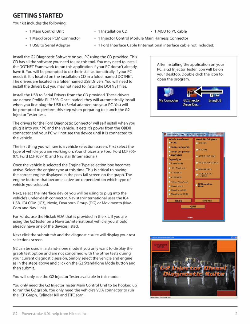
GETTING STARTEDYour kit includes the following:
• 1MainControlUnit • 1InstallationCD • 1MCUtoPCcable
• 1MaxxForcePCMConnector • 1InjectorControlModuleMainHarnessConnector
• 1USBtoSerialAdapter • 1FordInterfaceCable(Internationalinterfacecablenotincluded)
After installing the application on your PC, a G2 Injector Tester Icon will be on your desktop. Double click the icon to open the program.
Install the G2 Diagnostic Software on you PC using the CD provided. This CD has all the software you need to use this tool. You may need to install the DOTNET Framework to run this application if your PC doesn’t already have it. You will be prompted to do the install automatically if your PC needs it. It is located on the installation CD in a folder named DOTNET. ThedriversarelocatedinafoldernamedUSBDrivers.Youwillneedtoinstall the drivers but you may not need to install the DOTNET files.
InstalltheUSBtoSerialDriversfromtheCDprovided.Thesedriversare named Prolific PL 2303. Once loaded, they will automatically install whenyoufirstplugtheUSBtoSerialadapterintoyourPC.Youwillbe prompted to perform this step when preparing to launch the G2 Injector Tester test.
The drivers for the Ford Diagnostic Connector will self install when you plugitintoyourPCandthevehicle.Itgetsit’spowerfromtheOBDIIconnector and your PC will not see the device until it is connected to the vehicle.
The first thing you will see is a vehicle selection screen. First select the typeofvehicleyouareworkingon.YourchoicesareFord,FordLCF(06-07),FordLCF(08-10)andNavistar(International)
Once the vehicle is selected the Engine Type selection box becomes active. Select the engine type at this time. This is critical to having the correct engine displayed in the pass fail screen on the graph. The engine buttons that become active are dependent on which type of vehicle you selected.
Next, select the interface device you will be using to plug into the vehicle’s under-dash connector. Navistar/International uses the IC4 USB,IC4COM(IC3),Nexiq,DearbornGroup(DG)orMovimento(Nav-ComandNav-Link)
For Fords, use the Hickok VDA that is provided in the kit. If you are using the G2 tester on a Navistar/International vehicle, you should already have one of the devices listed.
Next click the submit tab and the diagnostic suite will display your test selections screen.
G2 can be used in a stand-alone mode if you only want to display the graph test option and are not concerned with the other tests during your current diagnostic session. Simply select the vehicle and engine as in the steps above and click on the G2 Standalone Mode button and then submit.
You will only see the G2 Injector Tester available in this mode.
You only need the G2 Injector Tester Main Control Unit to be hooked up to run the G2 graph. You only need the vehicle’s VDA connector to run the ICP Graph, Cylinder Kill and DTC scan.
G2—Powerstroke 6.0L help from Hickok Inc. 3
The following screenshots will display the tests available in the G2 Diagnostic Suite. With each screenshot is the basic diagnostics you will follow to arrive at your conclusions.
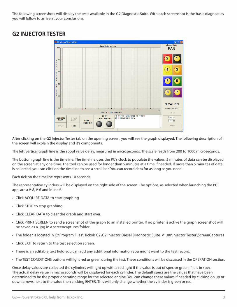
G2 INJECTOR TESTER
After clicking on the G2 Injector Tester tab on the opening screen, you will see the graph displayed. The following description of the screen will explain the display and it’s components.
The left vertical graph line is the spool valve delay, measured in microseconds. The scale reads from 200 to 1000 microseconds.
The bottom graph line is the timeline. The timeline uses the PC’s clock to populate the values. 5 minutes of data can be displayed on the screen at any one time. The tool can be used for longer than 5 minutes at a time if needed. If more than 5 minutes of data is collected, you can click on the timeline to see a scroll bar. You can record data for as long as you need.
Each tick on the timeline represents 10 seconds.
The representative cylinders will be displayed on the right side of the screen. The options, as selected when launching the PC app,areaV-8,V-6andInline6.
• ClickACQUIREDATAtostartgraphing
• ClickSTOPtostopgraphing.
• ClickCLEARDATAtoclearthegraphandstartover.
• ClickPRINTSCREENtosendascreenshotofthegraphtoaninstalledprinter.Ifnoprinterisactivethegraphscreenshotwillbe saved as a .jpg in a screencaptures folder.
• ThefolderislocatedinC:\ProgramFiles\HickokG2\G2InjectorDieselDiagnosticSuiteV1.00\InjectorTester\ScreenCaptures
• ClickEXITtoreturntothetestselectionscreen.
• Thereisaneditabletextfieldyoucanaddanyadditionalinformationyoumightwanttothetestrecord.
• TheTESTCONDITIONSbuttonswilllightredorgreenduringthetest.TheseconditionswillbediscussedintheOPERATIONsection.
Once delay values are collected the cylinders will light up with a red light if the value is out of spec or green if it is in spec. The actual delay value in microseconds will be displayed for each cylinder. The default specs are the values that have been determined to be the proper operating range for the selected engine. You can change these values if needed by clicking on up or down arrows next to the value then clicking ENTER. This will only change whether the cylinder is green or red.
G2—Powerstroke 6.0L help from Hickok Inc. 4
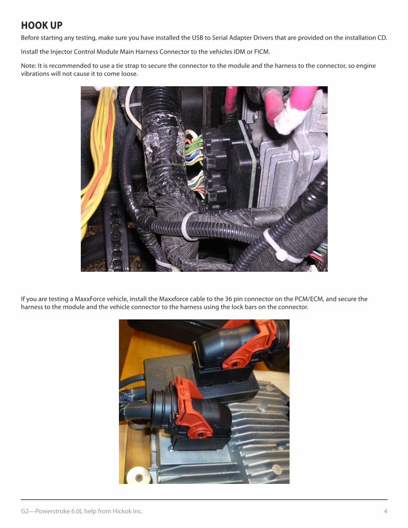
HOOK UpBeforestartinganytesting,makesureyouhaveinstalledtheUSBtoSerialAdapterDriversthatareprovidedontheinstallationCD.
Install the Injector Control Module Main Harness Connector to the vehicles IDM or FICM.
Note: It is recommended to use a tie strap to secure the connector to the module and the harness to the connector, so engine vibrations will not cause it to come loose.
If you are testing a MaxxForce vehicle, install the Maxxforce cable to the 36 pin connector on the PCM/ECM, and secure the harness to the module and the vehicle connector to the harness using the lock bars on the connector.
G2—Powerstroke 6.0L help from Hickok Inc. 5
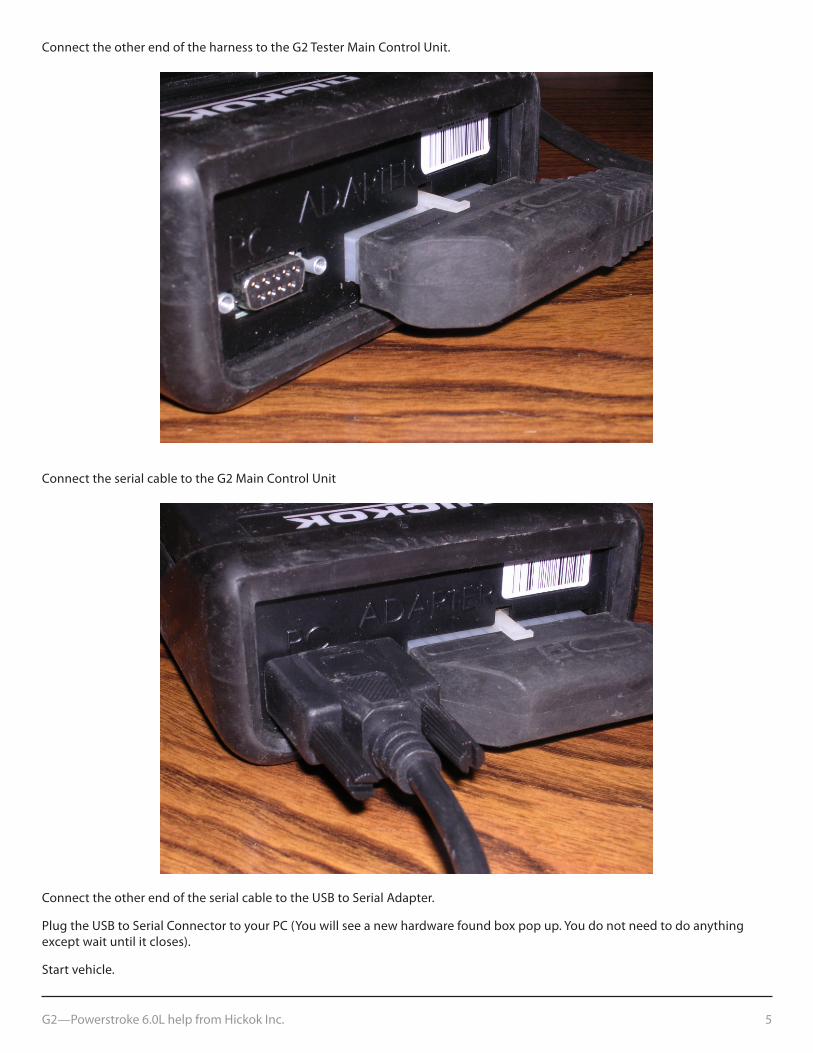
Connect the other end of the harness to the G2 Tester Main Control Unit.
Connect the serial cable to the G2 Main Control Unit
ConnecttheotherendoftheserialcabletotheUSBtoSerialAdapter.
PlugtheUSBtoSerialConnectortoyourPC(Youwillseeanewhardwarefoundboxpopup.Youdonotneedtodoanythingexceptwaituntilitcloses).
Start vehicle.
G2—Powerstroke 6.0L help from Hickok Inc. 6
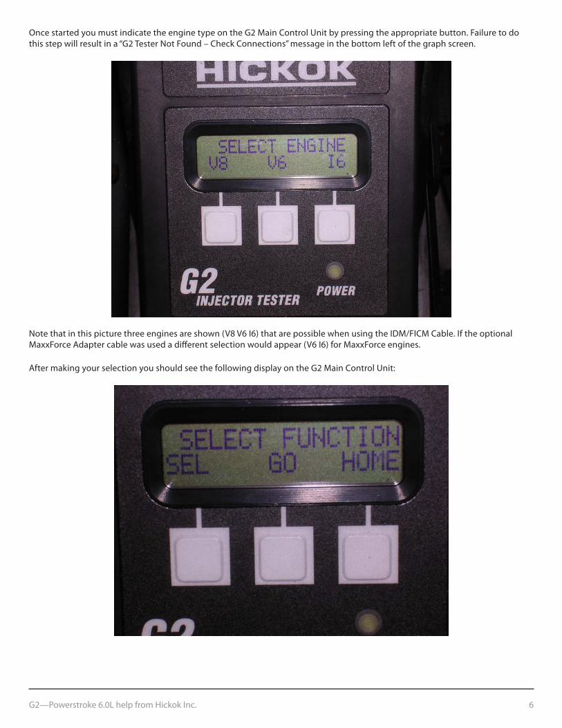
Once started you must indicate the engine type on the G2 Main Control Unit by pressing the appropriate button. Failure to do this step will result in a “G2 Tester Not Found – Check Connections” message in the bottom left of the graph screen.
Notethatinthispicturethreeenginesareshown(V8V6I6)thatarepossiblewhenusingtheIDM/FICMCable.IftheoptionalMaxxForceAdaptercablewasusedadifferentselectionwouldappear(V6I6)forMaxxForceengines.
After making your selection you should see the following display on the G2 Main Control Unit:
G2—Powerstroke 6.0L help from Hickok Inc. 7
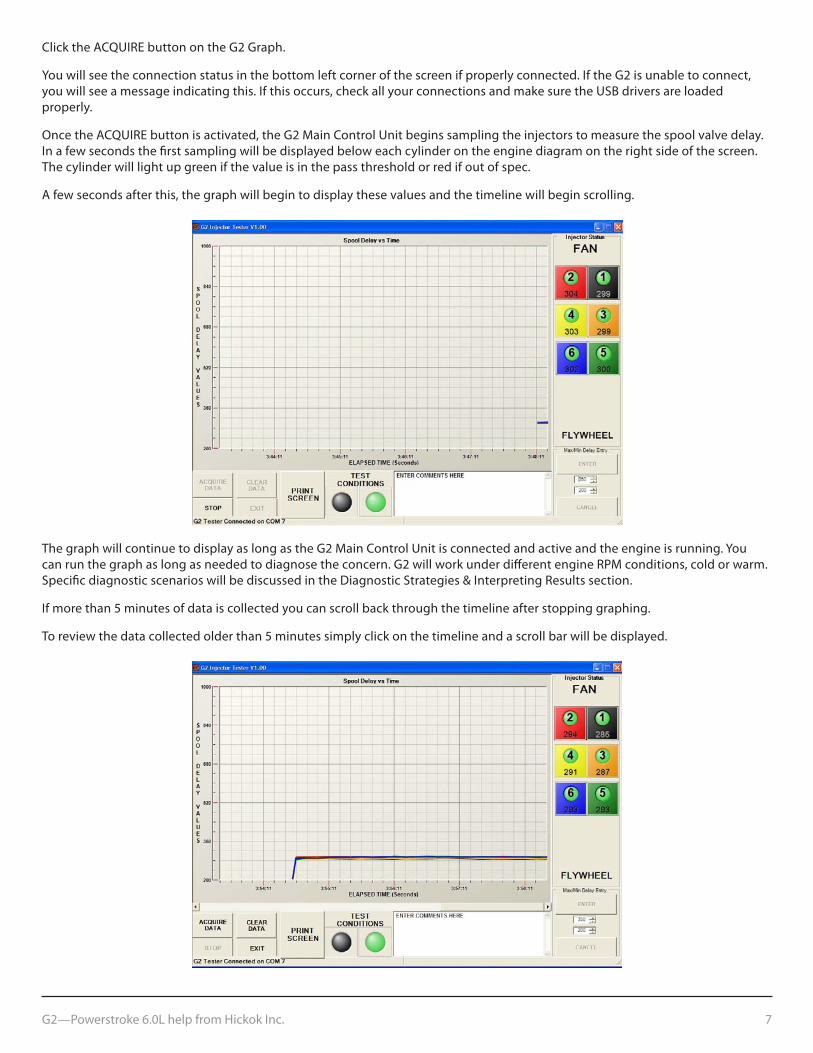
ClicktheACQUIREbuttonontheG2Graph.
You will see the connection status in the bottom left corner of the screen if properly connected. If the G2 is unable to connect, youwillseeamessageindicatingthis.Ifthisoccurs,checkallyourconnectionsandmakesuretheUSBdriversareloadedproperly.
OncetheACQUIREbuttonisactivated,theG2MainControlUnitbeginssamplingtheinjectorstomeasurethespoolvalvedelay.In a few seconds the first sampling will be displayed below each cylinder on the engine diagram on the right side of the screen. The cylinder will light up green if the value is in the pass threshold or red if out of spec.
A few seconds after this, the graph will begin to display these values and the timeline will begin scrolling.
The graph will continue to display as long as the G2 Main Control Unit is connected and active and the engine is running. You can run the graph as long as needed to diagnose the concern. G2 will work under different engine RPM conditions, cold or warm. Specific diagnostic scenarios will be discussed in the Diagnostic Strategies & Interpreting Results section.
If more than 5 minutes of data is collected you can scroll back through the timeline after stopping graphing.
To review the data collected older than 5 minutes simply click on the timeline and a scroll bar will be displayed.
G2—Powerstroke 6.0L help from Hickok Inc. 8
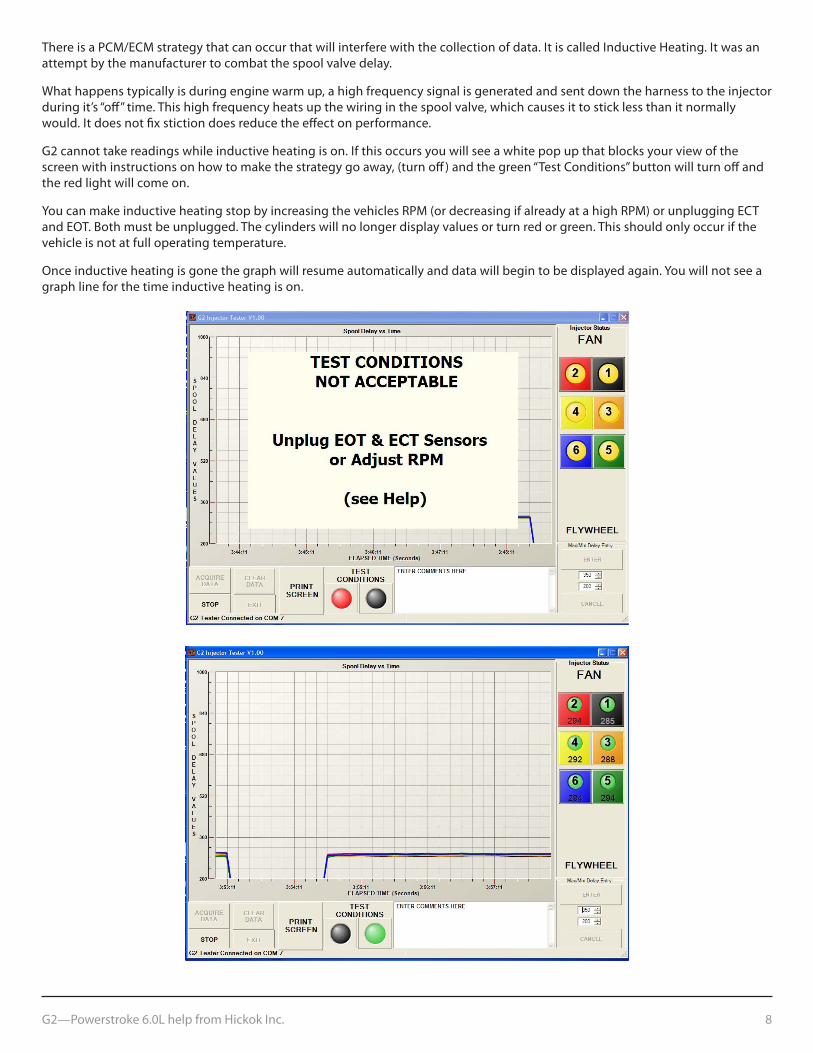
There is a PCM/ECM strategy that can occur that will interfere with the collection of data. It is called Inductive Heating. It was an attempt by the manufacturer to combat the spool valve delay.
Whathappenstypicallyisduringenginewarmup,ahighfrequencysignalisgeneratedandsentdowntheharnesstotheinjectorduringit’s“off”time.Thishighfrequencyheatsupthewiringinthespoolvalve,whichcausesittosticklessthanitnormallywould. It does not fix stiction does reduce the effect on performance.
G2 cannot take readings while inductive heating is on. If this occurs you will see a white pop up that blocks your view of the screenwithinstructionsonhowtomakethestrategygoaway,(turnoff)andthegreen“TestConditions”buttonwillturnoffandthe red light will come on.
YoucanmakeinductiveheatingstopbyincreasingthevehiclesRPM(ordecreasingifalreadyatahighRPM)orunpluggingECTandEOT.Bothmustbeunplugged.Thecylinderswillnolongerdisplayvaluesorturnredorgreen.Thisshouldonlyoccurifthevehicle is not at full operating temperature.
Once inductive heating is gone the graph will resume automatically and data will begin to be displayed again. You will not see a graph line for the time inductive heating is on.
G2—Powerstroke 6.0L help from Hickok Inc. 9
INTERpRETING THE GRApHInterpreting the readings that the G2 Injector Tester returns is key to getting to the root of the problem and repairing your vehicle. The following guide is to help you in the interpretation of the data. Keep in mind that although stiction will be present under any driving condition, the symptoms will vary. Some of the more common symptoms of Stiction are hard start, no start, white smoke and loss of power, typically under load.
Factors other than Stiction can cause or contribute to these symptoms. There are also other tools in the DiagnosticSuitecanhelppinpointiftheinjector(s)are causing the symptom.
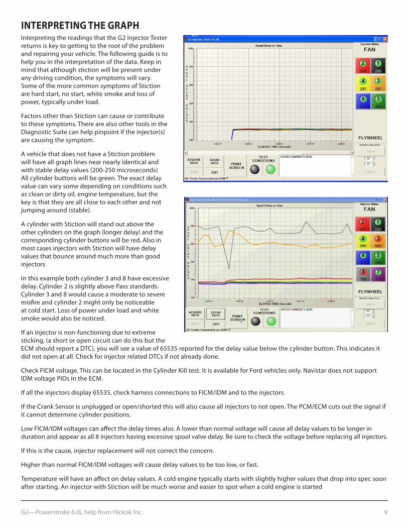
A vehicle that does not have a Stiction problem will have all graph lines near nearly identical and withstabledelayvalues(200-250microseconds)All cylinder buttons will be green. The exact delay value can vary some depending on conditions such as clean or dirty oil, engine temperature, but the key is that they are all close to each other and not jumpingaround(stable).
A cylinder with Stiction will stand out above the othercylindersonthegraph(longerdelay)andthecorresponding cylinder buttons will be red. Also in most cases injectors with Stiction will have delay values that bounce around much more than good injectors
Inthisexamplebothcylinder3and8haveexcessivedelay. Cylinder 2 is slightly above Pass standards. Cylinder3and8wouldcauseamoderatetoseveremisfire and cylinder 2 might only be noticeable at cold start. Loss of power under load and white smoke would also be noticed.
If an injector is non-functioning due to extreme sticking,(ashortoropencircuitcandothisbuttheECMshouldreportaDTC),youwillseeavalueof65535reportedforthedelayvaluebelowthecylinderbutton.Thisindicatesitdid not open at all. Check for injector related DTCs if not already done.
Check FICM voltage. This can be located in the Cylinder Kill test. It is available for Ford vehicles only. Navistar does not support IDM voltage PIDs in the ECM.
If all the injectors display 65535, check harness connections to FICM/IDM and to the injectors.
If the Crank Sensor is unplugged or open/shorted this will also cause all injectors to not open. The PCM/ECM cuts out the signal if it cannot determine cylinder positions.
Low FICM/IDM voltages can affect the delay times also. A lower than normal voltage will cause all delay values to be longer in durationandappearasall8injectorshavingexcessivespoolvalvedelay.Besuretocheckthevoltagebeforereplacingallinjectors.
If this is the cause, injector replacement will not correct the concern.
Higher than normal FICM/IDM voltages will cause delay values to be too low, or fast.
Temperature will have an affect on delay values. A cold engine typically starts with slightly higher values that drop into spec soon after starting. An injector with Stiction will be much worse and easier to spot when a cold engine is started
G2—Powerstroke 6.0L help from Hickok Inc. 10
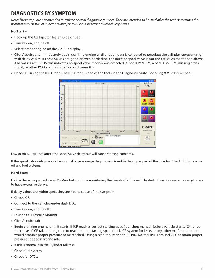
DIAGNOSTICS BY SYMpTOMNote: These steps are not intended to replace normal diagnostic routines. They are intended to be used after the tech determines the problem may be fuel or injector related, or to rule out injector or fuel delivery issues.
No Start –
• HookuptheG2InjectorTesterasdescribed.
• Turnkeyon,engineoff.
• SelectproperengineontheG2LCDdisplay.
• ClickAcquireandimmediatelybegincrankingengineuntilenoughdataiscollectedtopopulatethecylinderrepresentationwith delay values. If these values are good or even borderline, the injector spool valve is not the cause. As mentioned above,if all values are 65535 this indicates no spool valve motion was detected. A bad IDM/FICM, a bad ECM/PCM, missing cranksignal, or other PCM starting criteria could cause this.
• CheckICPusingtheICPGraph.TheICPGraphisoneofthetoolsintheDiagnosticSuite.SeeUsing ICP Graph Section.
Low or no ICP will not affect the spool valve delay but will cause starting concerns.
If the spool valve delays are in the normal or pass range the problem is not in the upper part of the injector. Check high-pressure oil and fuel systems.
Hard Start –
Follow the same procedure as No Start but continue monitoring the Graph after the vehicle starts. Look for one or more cylinders to have excessive delays.
If delay values are within specs they are not he cause of the symptom.
• CheckICP.
• ConnecttothevehiclesunderdashDLC.
• Turnkeyon,engineoff.
• LaunchOilPressureMonitor
• ClickAcquiretab.
• Begincrankingengineuntilitstarts.IfICPreachescorrectstartingspec(pershopmanual)beforevehiclestarts,ICPisnotthe cause. If ICP takes a long time to reach proper starting spec, check ICP system for leaks or any other malfunction thatwould prohibit proper pressure to be reached. Using a scan tool monitor IPR PID. Normal IPR is around 25% to attain properpressure spec at start and idle.
• IfIPRisnormalruntheCylinderKilltest.
• Checkfuelsystem.
• CheckforDTCs.
G2—Powerstroke 6.0L help from Hickok Inc. 11
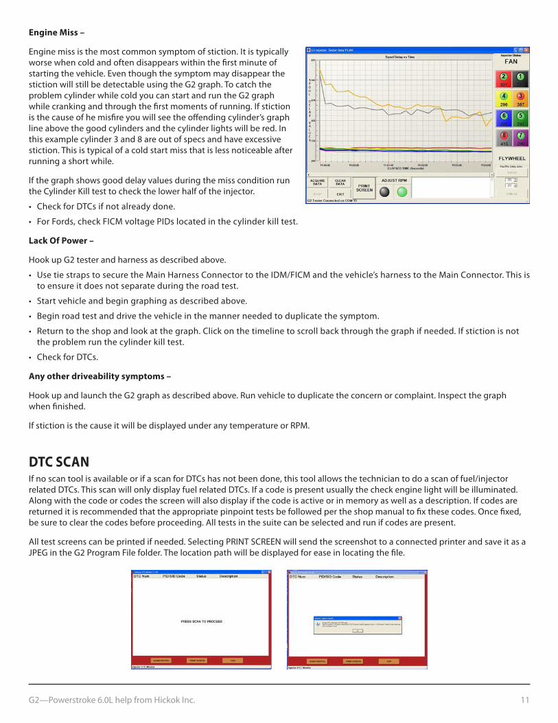
Engine Miss –
Engine miss is the most common symptom of stiction. It is typically worse when cold and often disappears within the first minute of starting the vehicle. Even though the symptom may disappear the stiction will still be detectable using the G2 graph. To catch the problem cylinder while cold you can start and run the G2 graph while cranking and through the first moments of running. If stiction is the cause of he misfire you will see the offending cylinder’s graph line above the good cylinders and the cylinder lights will be red. In thisexamplecylinder3and8areoutofspecsandhaveexcessivestiction. This is typical of a cold start miss that is less noticeable after running a short while.
If the graph shows good delay values during the miss condition run the Cylinder Kill test to check the lower half of the injector.
• CheckforDTCsifnotalreadydone.
• ForFords,checkFICMvoltagePIDslocatedinthecylinderkilltest.
Lack Of power –
Hook up G2 tester and harness as described above.
• UsetiestrapstosecuretheMainHarnessConnectortotheIDM/FICMandthevehicle’sharnesstotheMainConnector.Thisisto ensure it does not separate during the road test.
• Startvehicleandbegingraphingasdescribedabove.
• Beginroadtestanddrivethevehicleinthemannerneededtoduplicatethesymptom.
• Returntotheshopandlookatthegraph.Clickonthetimelinetoscrollbackthroughthegraphifneeded.Ifstictionisnotthe problem run the cylinder kill test.
• CheckforDTCs.
Any other driveability symptoms –
Hook up and launch the G2 graph as described above. Run vehicle to duplicate the concern or complaint. Inspect the graph when finished.
If stiction is the cause it will be displayed under any temperature or RPM.
DTC SCANIf no scan tool is available or if a scan for DTCs has not been done, this tool allows the technician to do a scan of fuel/injector related DTCs. This scan will only display fuel related DTCs. If a code is present usually the check engine light will be illuminated. Along with the code or codes the screen will also display if the code is active or in memory as well as a description. If codes are returned it is recommended that the appropriate pinpoint tests be followed per the shop manual to fix these codes. Once fixed, be sure to clear the codes before proceeding. All tests in the suite can be selected and run if codes are present.
All test screens can be printed if needed. Selecting PRINT SCREEN will send the screenshot to a connected printer and save it as a JPEG in the G2 Program File folder. The location path will be displayed for ease in locating the file.
G2—Powerstroke 6.0L help from Hickok Inc. 12
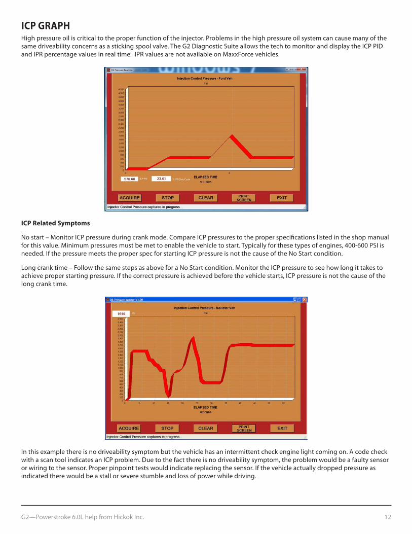
ICp GRApHHigh pressure oil is critical to the proper function of the injector. Problems in the high pressure oil system can cause many of the same driveability concerns as a sticking spool valve. The G2 Diagnostic Suite allows the tech to monitor and display the ICP PID and IPR percentage values in real time. IPR values are not available on MaxxForce vehicles.
ICp Related Symptoms
No start – Monitor ICP pressure during crank mode. Compare ICP pressures to the proper specifications listed in the shop manual for this value. Minimum pressures must be met to enable the vehicle to start. Typically for these types of engines, 400-600 PSI is needed. If the pressure meets the proper spec for starting ICP pressure is not the cause of the No Start condition.
Long crank time – Follow the same steps as above for a No Start condition. Monitor the ICP pressure to see how long it takes to achieve proper starting pressure. If the correct pressure is achieved before the vehicle starts, ICP pressure is not the cause of the long crank time.
In this example there is no driveability symptom but the vehicle has an intermittent check engine light coming on. A code check with a scan tool indicates an ICP problem. Due to the fact there is no driveability symptom, the problem would be a faulty sensor or wiring to the sensor. Proper pinpoint tests would indicate replacing the sensor. If the vehicle actually dropped pressure as indicated there would be a stall or severe stumble and loss of power while driving.
G2—Powerstroke 6.0L help from Hickok Inc. 13
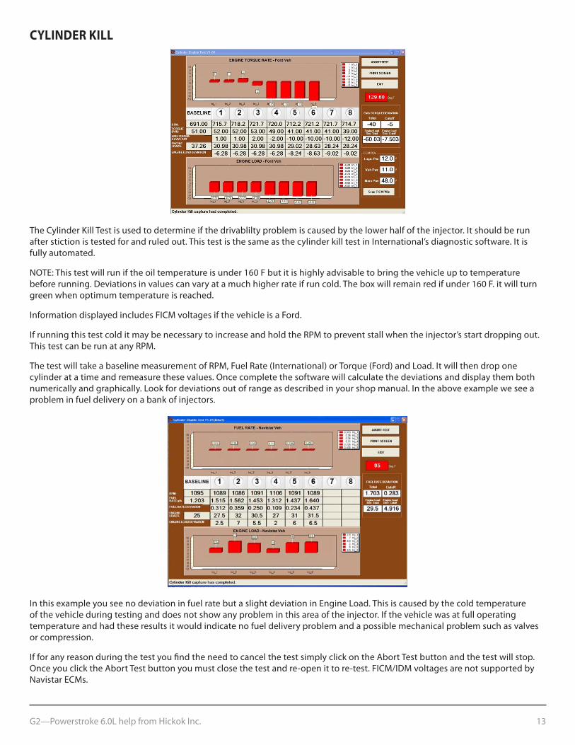
CYLINDER KILL
The Cylinder Kill Test is used to determine if the drivablilty problem is caused by the lower half of the injector. It should be run after stiction is tested for and ruled out. This test is the same as the cylinder kill test in International’s diagnostic software. It is fully automated.
NOTE: This test will run if the oil temperature is under 160 F but it is highly advisable to bring the vehicle up to temperature before running. Deviations in values can vary at a much higher rate if run cold. The box will remain red if under 160 F. it will turn green when optimum temperature is reached.
Information displayed includes FICM voltages if the vehicle is a Ford.
If running this test cold it may be necessary to increase and hold the RPM to prevent stall when the injector’s start dropping out. This test can be run at any RPM.
ThetestwilltakeabaselinemeasurementofRPM,FuelRate(International)orTorque(Ford)andLoad.Itwillthendroponecylinder at a time and remeasure these values. Once complete the software will calculate the deviations and display them both numerically and graphically. Look for deviations out of range as described in your shop manual. In the above example we see a problem in fuel delivery on a bank of injectors.
In this example you see no deviation in fuel rate but a slight deviation in Engine Load. This is caused by the cold temperature of the vehicle during testing and does not show any problem in this area of the injector. If the vehicle was at full operating temperature and had these results it would indicate no fuel delivery problem and a possible mechanical problem such as valves or compression.
If for any reason during the test you find the need to cancel the test simply click on the Abort Test button and the test will stop. Once you click the Abort Test button you must close the test and re-open it to re-test. FICM/IDM voltages are not supported by Navistar ECMs.
G2—Powerstroke 6.0L help from Hickok Inc. 14
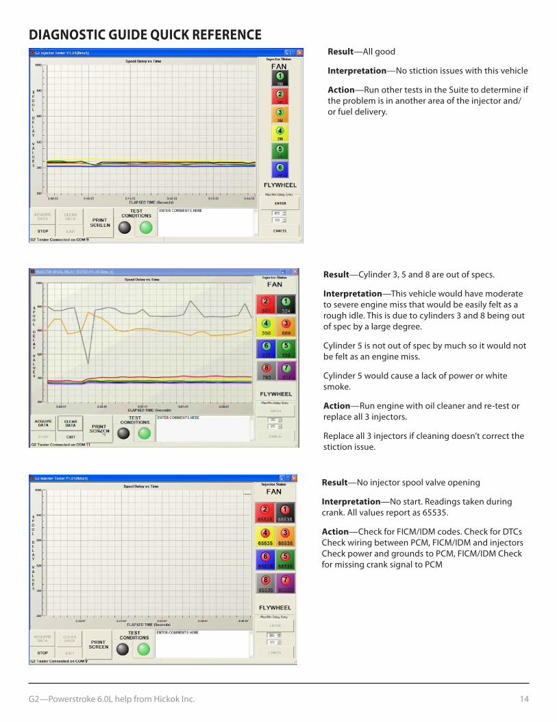
DIAGNOSTIC GUIDE QUICK REFERENCEResult—All good
Interpretation—No stiction issues with this vehicle
Action—Run other tests in the Suite to determine if the problem is in another area of the injector and/or fuel delivery.
Result—Cylinder3,5and8areoutofspecs.
Interpretation—This vehicle would have moderate to severe engine miss that would be easily felt as a roughidle.Thisisduetocylinders3and8beingoutof spec by a large degree.
Cylinder 5 is not out of spec by much so it would not be felt as an engine miss.
Cylinder 5 would cause a lack of power or white smoke.
Action—Run engine with oil cleaner and re-test or replace all 3 injectors.
Replace all 3 injectors if cleaning doesn’t correct the stiction issue.
Result—No injector spool valve opening
Interpretation—No start. Readings taken during crank. All values report as 65535.
Action—Check for FICM/IDM codes. Check for DTCs Check wiring between PCM, FICM/IDM and injectors Check power and grounds to PCM, FICM/IDM Check for missing crank signal to PCM
G2—Powerstroke 6.0L help from Hickok Inc. 15
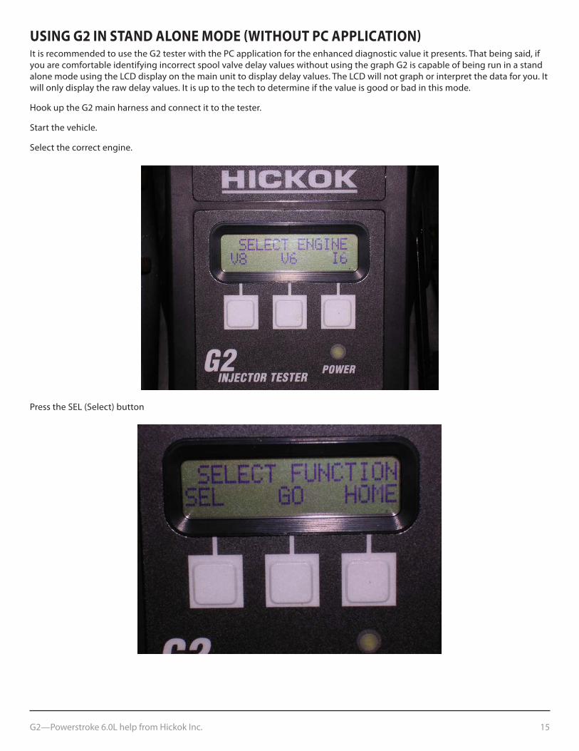
USING G2 IN STAND ALONE MODE (WITHOUT pC AppLICATION)It is recommended to use the G2 tester with the PC application for the enhanced diagnostic value it presents. That being said, if you are comfortable identifying incorrect spool valve delay values without using the graph G2 is capable of being run in a stand alone mode using the LCD display on the main unit to display delay values. The LCD will not graph or interpret the data for you. It will only display the raw delay values. It is up to the tech to determine if the value is good or bad in this mode.
Hook up the G2 main harness and connect it to the tester.
Start the vehicle.
Select the correct engine.
PresstheSEL(Select)button
G2—Powerstroke 6.0L help from Hickok Inc. 16
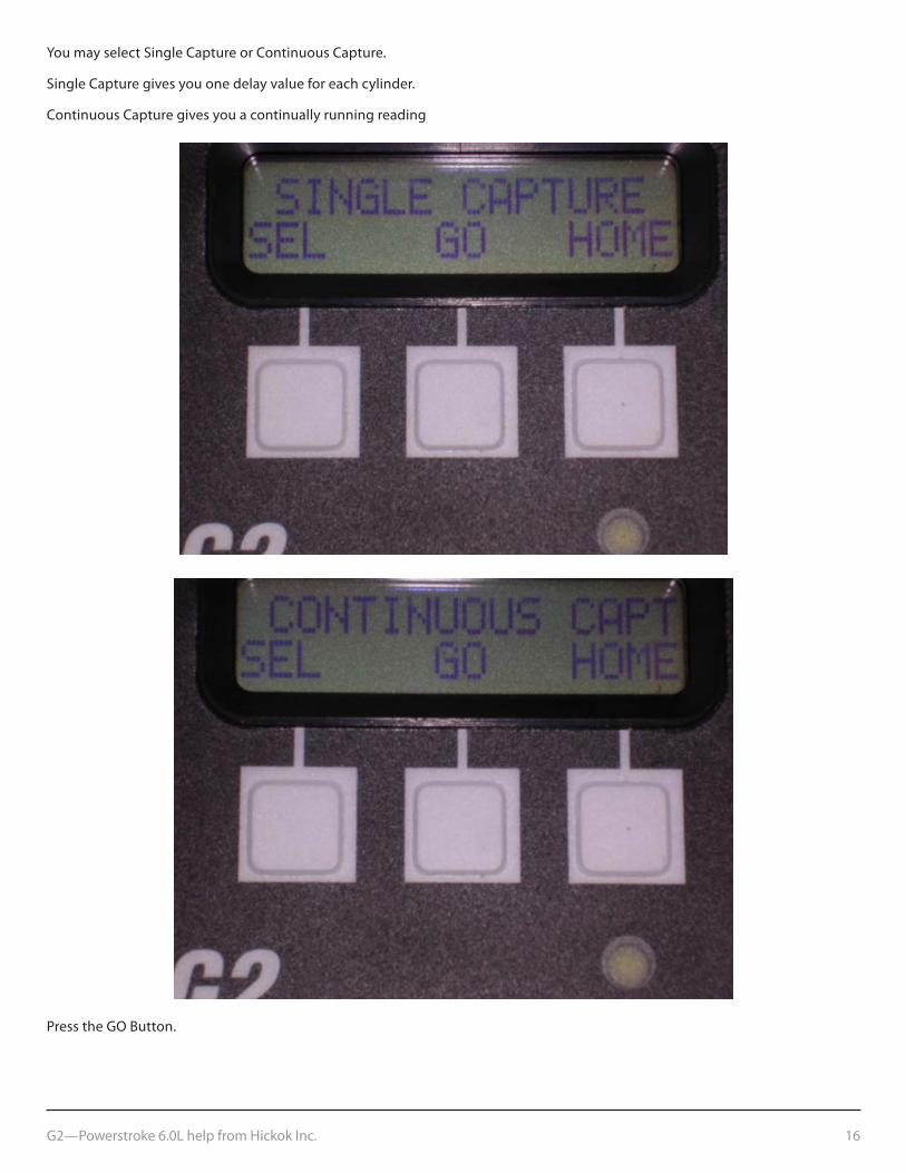
You may select Single Capture or Continuous Capture.
Single Capture gives you one delay value for each cylinder.
Continuous Capture gives you a continually running reading
PresstheGOButton.
G2—Powerstroke 6.0L help from Hickok Inc. 17
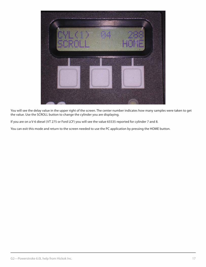
You will see the delay value in the upper right of the screen. The center number indicates how many samples were taken to get the value. Use the SCROLL button to change the cylinder you are displaying.
IfyouareonaV-6diesel(VT275orFordLCF)youwillseethevalue65535reportedforcylinder7and8.
You can exit this mode and return to the screen needed to use the PC application by pressing the HOME button.

18
Ifyouhaveanyquestionsaboutourproductsincludingtechnicalassistance,callourcustomercaredepartmentduringstandardbusinesshoursEST.Ifacustomercarerepresentativedirectsyoutoreturnanyequipment,besuretoincludetheseitems:
• awrittendescriptionoftheproblem;
• thenameandtelephonenumberofyourcontactperson;
• yourshippingaddress,and
• ourreturnauthorizationnumber(fromcustomercare).
©2012 Hickok Inc. All rights reserved. 02491-097