tesis doctoral: development of environmentally …
TRANSCRIPT

FACULTAD DE CIENCIAS
DEPARTAMENTO DE FÍSICA DE LA MATERIA CONDENSADA, CRISTALOGRAFÍA Y MINERALOGÍA
TESIS DOCTORAL:
DEVELOPMENT OF ENVIRONMENTALLY FRIENDLY CELLULAR POLYMERS FOR PACKAGING AND STRUCTURAL APPLICATIONS. STUDY OF THE RELATIONSHIP CELLULAR
STRUCTURE-MECHANICAL PROPERTIES
Presentada por Alberto López Gil para optar al grado de doctor por la Universidad de Valladolid
Dirigida por: Miguel Ángel Rodríguez Pérez


AGRADECIMIENTOS
En primer lugar, me gustaría expresar mi más sincera gratitud a mi director de tesis Miguel
Ángel Rodríguez. No solo por haber hecho posible la realización de esta tesis doctoral sino
también, y posiblemente el motivo principal, por haberme enseñado a pensar.
De una forma muy especial me gustaría agradecerle a José Antonio de Saja Sáez la oportunidad
que me dio de entrar en el grupo y permitirme de este modo, haber completado la que ha sido
hasta ahora la etapa más formativa e importante de mi vida.
Por supuesto, quiero agradecer la ayuda recibida durante estos años de trabajo a todos y cada
uno de los miembros del grupo CellMat, tanto a los que lo constituyen ahora como a los que ya
han pasado por él. Sin embargo, me gustaría dar las gracias de una forma más especial a
aquellos con los que he tenido la oportunidad de compartir momentos más íntimos tanto
dentro como fuera del ámbito del laboratorio: Dani, Josías, Samu, Javi, Cristina y Ester.
Una de las etapas más especiales de este doctorado fue mi estancia en el grupo LTBA de la
Universidade Estadual Paulista de Presidente Prudente en Brasil. Es por ello que me gustaría
dedicar una parte de estos agradecimientos al profesor Aldo Eloizo Job por la oportunidad que
me brindo al poder trabajar en su grupo de investigación. Estos agradecimientos se extienden
a Felipe por la ayuda que me prestó tanto durante su etapa en España como durante la mía en
Brasil. Por último, a todas las personas que componen el grupo de investigación que me
trataron como si fuese uno más a pesar de las barreras lingüísticas. Muito obrigado gente!
Vocês fizeram com que eu me sentisse parte do grupo!
También me gustaría dar las gracias a todos mis amigos. Tanto a los que no han entendido mi
ausencia como a aquellos que a pesar de los pesares, continúan estando ahí.
Por último, me gustaría dar las gracias desde lo más profundo de mi corazón a mis padres, a mi
hermano y a Leandra, ya que son las personas que más han sufrido junto conmigo los avatares
que conlleva la realización de una tesis doctoral pero que sin embargo, me han apoyado de
forma incondicional.


FINANCIACIÓN
He de agradecer la financiación para llevar a cabo esta investigación que he recibido de
diversas instituciones. En primer lugar agradecer al MICINN por la beca FPI referencia BES-
2010-038746. Además quiero agradecer la financiación recibida por el grupo CellMat,
proveniente de los siguientes proyectos de investigación:
• Desarrollo de plásticos sub-microcelulares y nanocelulares: fabricación, estructura,
propiedades y potenciales aplicaciones (MAT2012-34901). Financiado por el Programa
Nacional de Materiales (MICIN).
• Desarrollo de una nueva generación de aislantes térmicos avanzados basados en la
obtención de estructuras porosas nanocelulares (VA035U13). Financiado por la Junta
de Castilla y León.
• Envasado activo y biodegradable para alimentos frescos (ACTIBIOPACK). Financiado
por el Ministerio de Economía y Competitividad. Ref: IPT-2011-1662-060000.
• Nancore: Microcellular nanocomposite for substitution of Balsa wood and PVC core
material (FP7. 214148). Fiananciado por VII Framework Program (Comisión Europea).
FUNDING
Financial support from FPI grant ref: BES-2010-038746 from MICINN is gratefully
acknowledged. Financial assistance provided by the following research projects is also
acknowledged:
• Desarrollo de plásticos sub-microcelulares y nanocelulares: fabricación, estructura,
propiedades y potenciales aplicaciones (MAT2012-34901). Funded by the National
Programme of Materials (MICINN).
• Desarrollo de una nueva generación de aislantes térmicos avanzados basados en la
obtención de estructuras porosas nanocelulares (VA035U13). Funded by Junta de
Castilla y León.
• Envasado activo y biodegradable para alimentos frescos (ACTIBIOPACK). Funded by the
Ministry of Economy and Competitiveness. Ref: IPT-2011-1662-060000.
• Nancore: Microcellular nanocomposite for substitution of Balsa wood and PVC core
material (FP7. 214148). Funded by the VII Framework Program (European
Commission).


CONTENTS


0- Resumen en Español
0.1- Introducción ...................................................................................................................................... R.5
0.2- Marco de desarrollo de la tesis dentro del grupo de investigación. ................................................ R.6
0.3- Objetivos ............................................................................................................................................ R.7
0.3.1- Almidón ...................................................................................................................................... R.7
0.3.2- Polipropileno. ............................................................................................................................. R.8
0.4- Contenidos. ........................................................................................................................................ R.9
0.5- Publicaciones, congresos y actividades relacionadas con la tesis. ................................................ R.10
0.6- Metodología de trabajo .................................................................................................................. R.12
0.6.1- Selección de materias primas ................................................................................................... R.12
0.6.2- Procesos de fabricación. ........................................................................................................... R.14
0.6.2.1- Espumado por radiación microondas. .............................................................................. R.15
0.6.2.2- Espumado mediante moldeo por compresión mejorado (ICM). ...................................... R.15
0.6.3- Métodos de caracterización. .................................................................................................... R.16
0.7- Principales resultados y conclusiones ............................................................................................ R.17
0.7.1- Almidón .................................................................................................................................... R.17
0.7.2- Polipropileno ............................................................................................................................ R.21
1- Introduction
1.1- Introduction ....................................................................................................................................... 5
1.2- Framework and motivation .............................................................................................................. 7
1.2.1- Backgrounds of the polymer foam industry ............................................................................... 7
1.2.2- Environmental concerns ............................................................................................................. 8
1.2.3- Towards the development of sustainable polymer foams ....................................................... 10
1.2.3.1- Bioplastics ......................................................................................................................... 10
1.2.3.2- Non-crosslinked polymers ................................................................................................ 13
1.2.4- CellMat Laboratory research .................................................................................................... 15
1.2.4.1- Actbiopack ........................................................................................................................ 16
1.2.4.2- Nancore ............................................................................................................................ 17
1.3- Objectives ........................................................................................................................................ 20
1.3.1- Starch ....................................................................................................................................... 20
1.3.2- Polypropylene .......................................................................................................................... 21
1.4- Contents........................................................................................................................................... 22
1.5- Publications and Conferences ......................................................................................................... 24

2-Background and State of the Art
2.1- Introduction ..................................................................................................................................... 35
2.2- Cellular materials ............................................................................................................................ 36
2.3- Polymer foams: fundamentals of foaming ..................................................................................... 37
2.4- Cellular structure-mechanical properties relationship in polymer foams..................................... 41
2.4.1- Improving the cellular structure: the role of Anisotropy ......................................................... 46
2.4.1.1- Rectangular cell model ..................................................................................................... 47
2.4.1.2- Tetrakaidecahedron cell model ........................................................................................ 49
2.4.2- Reinforcement with fillers: polymer composites ..................................................................... 51
2.4.2.1- Natural fibres .................................................................................................................... 52
2.4.2.2- Starch-based biocomposites ............................................................................................ 54
2.4.2.3- Polymer nanonocomposites: nanoclays ........................................................................... 62
2.5- Starch-based foams ......................................................................................................................... 67
2.5.1- Starch foaming processes ......................................................................................................... 70
2.5.1.1- Extrusion foaming ............................................................................................................. 70
2.5.1.2- Baking ............................................................................................................................... 71
2.5.1.3- Microwave foaming .......................................................................................................... 72
2.5.2- Starch foams reinforced with natural fibres ............................................................................ 75
2.5.3- Summary .................................................................................................................................. 77
2.6- Polypropylene-based foams ........................................................................................................... 79
2.6.1- Polypropylene foaming processes............................................................................................ 80
2.6.1.1- Extrusion foaming ............................................................................................................. 80
2.6.1.2- Compression moulding ..................................................................................................... 81
2.6.1.3- Moulded-bead process ..................................................................................................... 83
2.6.2- Polypropylene foams in the market: development of branched polypropylenes ................... 84
2.6.3- Foamed polypropylene nanocomposites ................................................................................. 85
2.6.4- Practical use of polypropylene foams as the core of sandwich panels .................................... 86
2.6.5- Summary .................................................................................................................................. 88

3-Materials, production processes and characterization techniques
3.1- Materials ........................................................................................................................................... 101
3.1.1- Starch based materials .............................................................................................................. 101
3.1.1.1- Polymer matrix: starch ...................................................................................................... 101
3.1.1.2- Plasticizers ......................................................................................................................... 101
3.1.1.3- Natural Fillers .................................................................................................................... 102
3.1.1.4- Blowing agent: water......................................................................................................... 103
3.1.1.5- Salt (NaCl) .......................................................................................................................... 103
3.1.2- Polypropylene based materials ................................................................................................. 103
3.1.2.1- Polymer matrix: polypropylene ......................................................................................... 103
3.1.2.2- Compatibilizer ................................................................................................................... 104
3.1.2.3- Fillers ................................................................................................................................. 105
3.1.2.4- Blowing agent .................................................................................................................... 105
3.1.2.5- Antioxidants....................................................................................................................... 106
3.2- Production processes ....................................................................................................................... 107
3.2.1- Bio and nanocomposites production by melt-blending ............................................................ 107
3.2.1.1- Starch-based biocomposites ............................................................................................. 109
3.2.1.2- Polypropylene-based nanocomposites ............................................................................. 111
3.2.2- Microwave foaming of starch ................................................................................................... 113
3.2.2.1- The interaction of water with microwaves ....................................................................... 113
3.2.2.2- Production of starch foamed blocks by microwave radiation ........................................... 117
3.3- Characterization techniques ............................................................................................................ 125
4-Development of starch-based materials
4.1- Introduction ...................................................................................................................................... 131
4.2- Solid starch-based biocomposites ................................................................................................... 133
4.3- Foamed starch-based biocomposites .............................................................................................. 141
4.4- Conclusions ....................................................................................................................................... 154 5-Development of polypropylene foams.
5.1- Introduction ...................................................................................................................................... 161
5.2- Production of medium-high density PP-based foams ..................................................................... 164
5.3- Production of low-density PP-based foams .................................................................................... 167
5.4- Conclusions ....................................................................................................................................... 202

6-Production of prototypes. Applicability of the developed materials
6.1- Introduction ...................................................................................................................................... 209
6.2- Bioderived and biodegradable food-packaging trays based on TPS ............................................... 211
6.2.1- Solid and flexible starch-based trays ......................................................................................... 211
6.2.2- Foamed rigid trays ..................................................................................................................... 216
6.2.3- Economic evaluation. ................................................................................................................ 218
6.2.4- Biodegradability tests ................................................................................................................ 221
6.2.5- Conclusions ................................................................................................................................ 225
6.3- Non cross-linked PP foamed panels as the cores of sandwich panels........................................... 226
6.3.1- An alternative rigid foam for structural applications in the market: ANICELL ........................... 228
6.3.2- Comparison with PVC and PET foams ........................................................................................ 230
6.3.3- Conclusions ................................................................................................................................ 233 7-Conclusions and Future work
7.1- Conclusions ....................................................................................................................................... 241
7.1.1- Starch ........................................................................................................................................ 241
7.1.2- Polyproylene ............................................................................................................................. 243
7.2- Future work ...................................................................................................................................... 247
7.2.1- Development of starch-based materials ................................................................................... 247
7.2.2- Development of polypropylene foams. ..................................................................................... 247 ANNEX. Patent: Method for producing cellular materials having a thermoplastic matrix

CHAPTER 0:
RESUMEN EN ESPAÑOL


Contenidos
0.1‐ Introducción ........................................................................................................................ R.5 0.2‐ Marco de desarrollo de la tesis dentro del grupo de investigación. ................................ R.6 0.3‐ Objetivos ............................................................................................................................. R.7
0.3.1‐ Almidón ........................................................................................................................ R.7 0.3.2‐ Polipropileno. ............................................................................................................... R.8
0.4‐ Contenidos. ......................................................................................................................... R.9 0.5‐ Publicaciones, congresos y actividades relacionadas con la tesis. ................................. R.10 0.6‐ Metodología de trabajo ................................................................................................... R.12
0.6.1‐ Selección de materias primas .................................................................................... R.12 0.6.2‐ Procesos de fabricación. ............................................................................................ R.14
0.6.2.1‐ Espumado por radiación microondas. ................................................................ R.15 0.6.2.2‐ Espumado mediante moldeo por compresión mejorado (ICM). ....................... R.15
0.6.3‐ Métodos de caracterización. ..................................................................................... R.16 0.7‐ Principales resultados y conclusiones .............................................................................. R.17
0.7.1‐ Almidón ...................................................................................................................... R.17 0.7.3‐ Polipropileno .............................................................................................................. R.21

Capítulo 0
R.4

Resumen en Español
R.5
0.1‐ Introducción
La industria del plástico y la comunidad científica, ante la problemática medioambiental causada por las enormes cantidades de residuos plásticos que se generan, están dirigiendo sus esfuerzos hacia el desarrollo de nuevos procesos y materiales poliméricos que sean más sostenibles con el medio ambiente. Este trabajo tratará de aportar soluciones a este problema dentro de los sectores del envasado de alimentos, del embalaje de protección y de paneles estructurales de baja densidad mediante el desarrollo de formulaciones y procesos a escala de laboratorio que se puedan emplear para la producción de materiales celulares poliméricos ambientalmente sostenibles.
En este sentido se emplearán dos tipos de matrices poliméricas con características muy diferentes: por un lado, un polímero completamente bioderivado y biodegradable como el almidón y por otro lado, un polipropileno ramificado con alta resistencia en fundido y que no requiere de un proceso de reticulación para alcanzar altos ratios de expansión. A pesar de las interesantes propiedades que estos polímeros presentan de partida, todavía se necesitan resolver ciertos aspectos para su aplicación extensiva en los sectores mencionados anteriormente.
Por una parte, el almidón es un polímero que requiere de un proceso previo de plastificación para obtener una matriz termoplástica que pueda ser procesada en equipos industriales (extrusoras, prensas de termoconformado etc.). Este proceso de plastificación disminuye de forma considerable las propiedades mecánicas del polímero (dependiendo del contenido de plastificante) lo que ocasiona que no tenga la rigidez y resistencia adecuadas para remplazar a polímeros derivados del petróleo habitualmente empleados en la fabricación de envases sólidos como el polietileno‐tereftalato (PET) y el polipropileno (PP). Además, cuando el almidón es sometido a un proceso de espumado para su aplicación como material de envasado y de embalaje de protección, las estructuras celulares que se obtienen son poco homogéneas y por tanto, las propiedades mecánicas resultantes son inferiores a las de materiales celulares basados en polímeros sintéticos como el XPS y el EPS habitualmente empleados en estos sectores. Por otra parte, los materiales celulares basados en polipropilenos ramificados que se han producido hasta ahora mediante procesos de espumado por extrusión presentan estructuras celulares muy pobres. Este hecho ha impedido la utilización extensiva de este material en el sector de los paneles estructurales de baja densidad en el que se requieren materiales celulares con estructuras celulares homogéneas y con celdas cerradas.
El trabajo desarrollado en esta tesis ha afrontado el desafío de desarrollar materiales celulares basados en estos polímeros con propiedades mecánicas óptimas. Para ello se han utilizado estrategias basadas en la modificación pre‐espumado de las propiedades del polímero mediante el uso de partículas micro y nanométricas y se han utilizado procesos de producción a escala de laboratorio novedosos en el campo de los materiales celulares. En el caso del almidón, se ha utilizado un proceso de expansión por radiación microondas con menores consumos de energía y con transferencias de calor más homogéneas (calentamiento en volumen) que en los procesos

Capítulo 0
R.6
convencionales (extrusión y baking). En el caso del polipropileno, se ha utilizado un proceso de espumado desarrollado en el propio grupo de investigación (CellMat Laboratory) y conocido como moldeo por compresión mejorado (ICM), el cual permite obtener materiales celulares de baja densidad y con una forma definida sin la necesidad de reticular el polímero previamente. Además, se ha utilizado una metodología de trabajo basada en establecer la relación estructura celular‐propiedades mecánicas, y que ha sido apoyada en el uso de modelos analíticos ampliamente utilizados en el campo de los materiales celulares. Esta metodología de trabajo ha permitido entender de forma más clara lo que ocurre en el proceso de producción y las estructuras y propiedades mecánicas finalmente obtenidas
0.2‐ Marco de desarrollo de la tesis dentro del grupo de investigación
Esta tesis se ha desarrollado en el Laboratorio de Materiales Celulares (CellMat Laboratory) de la Universidad de Valladolid, un grupo de investigación fundado en 1999 por los profesores Jose Antonio de Saja Sáez y Miguel Ángel Rodríguez Pérez con el objetivo de desarrollar nuevo conocimiento científico en el área de los materiales celulares. En sus comienzos, el grupo estuvo centrado principalmente en establecer la relación estructura‐propiedades pero a lo largo del tiempo se han establecido varias líneas de investigación relacionadas con el desarrollo de nuevos materiales celulares avanzados. Uno de los propósitos del grupo es proveer a la industria con nuevas formulaciones y procesos capaces de mejorar a los materiales celulares existentes actualmente en el mercado y al mismo tiempo, contribuir a crear nuevo conocimiento científico en relación a los mecanismos de espumado inherentes a estos procesos de fabricación y a la relación proceso‐formulación‐estructura‐propiedades en los materiales desarrollados.
Las líneas de investigación que actualmente son abordadas por el grupo de investigación relacionadas con materiales celulares poliméricos son: materiales microcelulares, materiales nanocelulares, nanocomposites celulares y biomateriales celulares (Figura 1.9). Esta tesis se enmarca en dos de estas líneas. Concretamente en las referentes al desarrollo de nanocomposites celulares y al desarrollo de biomateriales celulares.[1,2, 3,4,5,6,7,8,9,10,11,12,13]
El creciente uso de materiales celulares poliméricos en diversos sectores (envasado, construcción, automoción etc.) y la consecuente generación de enormes cantidades de residuos derivados de los mismos han repercutido en que una de las líneas de investigación que más crecimiento ha experimentado en los últimos años en CellMat Laboratory sea la relacionada con el desarrollo de biomateriales celulares. En este sentido, una parte muy representativa de las investigaciones realizadas por el grupo tienen relación con este tema [1‐13].
Además, el grupo de investigación ha estado involucrado de forma muy intensa en el desarrollo de proyectos de investigación con financiación pública relacionados con los temas de investigación abordados en esta tesis. Por un lado, ACTIBIOPACK es un proyecto financiado por el gobierno español en la convocatoria INNPACTO de 2011 en el cual se desarrollaron formulaciones bioderivadas y biodegradables para la fabricación de bandejas de alimentación sólidas y espumadas. El proyecto fue constituido por un consorcio muy amplio con

Resumen en Español
R.7
representación de los ámbitos tanto académico como privado. Los miembros de este consorcio se recogen en la Tabla 1.1. Por otro lado, el proyecto NANCORE fue un proyecto financiado por el séptimo programa marco de la Unión Europea (FP7) y cuyo principal objetivo fue el desarrollo de paneles rígidos basados en nanocomposites microcelulares de baja densidad con propiedades similares y con un coste inferior a los que se emplean actualmente en el mercado (espuma de PVC y madera de balsa). Es por ello que una de las soluciones planteadas en el proyecto fue el uso de matrices poliméricas basadas en poliolefinas como es el caso del polipropileno ramificado que se ha empleado a lo largo de esta tesis. El proyecto fue constituido por un consorcio muy variado de instituciones públicas y privadas de distintos países de la Unión Europea como se puede ver en la Tabla 1.2.
0.3‐ Objetivos
El principal objetivo de este trabajo es el desarrollo y fabricación de nuevos materiales poliméricos sólidos y celulares que sean capaces de ofrecer alternativas ambientalmente sostenibles a los materiales que actualmente se emplean en envases de alimentación, embalajes de protección y en paneles estructurales ligeros. Este será el objetivo común a todos los trabajos desarrollados en esta tesis aunque se han establecido objetivos específicos para cada uno de los polímeros estudiados: almidón y polipropileno.
0.3.1‐ Almidón
El uso de almidón como matriz polimérica para la producción de bandejas de alimentación y de embalajes de protección todavía requiere afrontar ciertos desafíos relacionados por un lado, con las pobres propiedades mecánicas obtenidas tras el proceso de plastificación y por otro lado, con su pobre comportamiento en espumado, lo cual repercute en la obtención de materiales celulares con estructuras celulares no homogéneas y por tanto, con pobres propiedades mecánicas.
Una de las estrategias implementadas durante esta tesis ha sido la modificación de las propiedades del polímero mediante su refuerzo con fibras naturales. En principio, la producción de este tipo de biocomposites debería repercutir en un incremento de las propiedades mecánicas de la matriz termoplástica de almidón de partida ya que la composición química de ambos materiales es similar (moléculas de glucosa). Sin embargo, después de realizar una exhaustiva revisión de la literatura científica relacionada (sección 2.5.2) se detectó que todavía existe un gran desconocimiento sobre como fibras naturales con tamaños micrométricos (como las empleadas en esta tesis) influyen en los mecanismos de espumado básicos y por tanto, en las estructuras celulares y propiedades mecánicas finalmente obtenidas. En cuanto al método de fabricación de las espumas, todavía existen pocos trabajos en literatura que aborden la obtención de espumas de almidón para aplicaciones no alimenticias mediante la utilización de microondas. Además, no se han encontrado estudios en los que se utilicen fibras naturales como refuerzo de la matriz de almidón en este tipo de proceso de espumado.

Capítulo 0
R.8
Teniendo en cuenta todos estos factores se han establecido varios objetivos como los que se enumeran a continuación:
1‐ Desarrollo de formulaciones bioderivadas y biodegradables basadas en almidón termoplástico (TPS) y optimización de los métodos de fabricación empleados a escala de laboratorio: extrusión, termoconformado y expansión por radiación microondas, necesarios para la obtención de materiales sólidos y espumados.
2‐ Mejora de los propiedades mecánicas de los materiales sólidos y espumados basados en TPS mediante el refuerzo con fibras naturales.
3‐ Estudio del efecto que las fibras naturales tienen en las propiedades mecánicas de los materiales desarrollados. En el caso de los materiales celulares el estudio abordará también cuál es el efecto que estas fibras tienen en los mecanismos básicos de formación de una estructura celular.
4‐ Analizar en detalle la relación estructura‐propiedades mecánicas en estos materiales.
5‐ Describir los resultados mecánicos obtenidos mediante el empleo de modelos analíticos encontrados en literatura como es el caso del modelo de celda abierto de Gibson y Ashby [14].
6‐ Evaluar si los métodos de fabricación y las formulaciones desarrolladas pueden ser empleadas para la producción de bandejas de envasado alimenticio y para la producción de embalajes de protección espumados con formas definidas.
0.3.2‐ Polipropileno
El uso de espumas de polipropileno en aplicaciones estructurales ha estado de alguna forma limitado hasta hoy por el pobre rendimiento de este polímero en proceso de espumado y como consecuencia, por las pobres propiedades mecánicas finalmente obtenidas. A pesar de los mejores rendimientos ofrecidos por los polipropilenos ramificados (mayor capacidad de expansión volumétrica) con respecto a polipropilenos de cadena lineal, las estructuras celulares así como las propiedades mecánicas de los materiales celulares finalmente desarrollados están todavía lejos de las estructuras y propiedades de materiales como la madera de balsa y las espumas de PVC reticuladas de celda cerrada (materiales que acaparan la mayor cuota de mercado en estas aplicaciones). En principio, el uso de nanoarcillas como partícula de refuerzo en la matriz polimérica debería suponer una solución innovadora a este problema. Sin embargo, aunque es una solución ampliamente utilizada y estudiada en literatura científica, todavía no ha dado los resultados esperados. En esta tesis se ha llevado a cabo una extensa revisión de la literatura científica relacionada con el tema (secciones 2.6.3y sección 5.3) que ha permitido detectar como todavía existe un claro desconocimiento sobre la relación proceso‐estructura‐propiedades de estos materiales heterogéneos (polímero‐gas‐nanopartícula). Este trabajo tratará de afrontar estos desafíos estableciendo los siguientes objetivos:

Resumen en Español
R.9
1‐ Desarrollo de formulaciones y optimización de un proceso de producción a escala de laboratorio conocido como moldeo por compresión mejorado (ICM)y que fue previamente desarrollado en CellMat Laboratory [15].
2‐ Evaluar la influencia que parámetros de producción como la presión, temperatura/tiempo y el contenido de agente espumante (claves en el proceso ICM) pueden tener en la estructura celular y por tanto, en las propiedades mecánicas de los materiales celulares desarrollados.
3‐ Evaluar el efecto de las nanoarcillas y de la presión externa aplicada sobre el material precursor en la estructura celular y por tanto, en las propiedades mecánicas de espumas de polipropileno de baja densidad.
4‐ Correlacionar las propiedades mecánicas medidas experimentales con las estructuras celulares (análisis de la relación estructura‐propiedades)
5‐ Utilizar modelos analíticos encontrados en literatura para describir con mayor precisión el comportamiento mecánico de los materiales celulares desarrollados como el modelo de Huber y Gibson y el modelo de Kelvin [16,17,18].
6‐ Evaluar si las espumas de polipropileno finalmente obtenidas podrían reemplazar a materiales poliméricos habitualmente empleados para aplicaciones estructurales como es el caso de las espumas de PVC reticuladas de celda cerrada y espumas de PET.
0.4‐ Contenidos
Esta tesis se divide en siete capítulos, de los cuales dos de ellos (4 y 5) incluyen un compendio de cuatro artículos: tres de ellos ya publicados en revistas científicas internacionales y un cuarto enviado pero aún no publicado. En el capítulo 4 se incluyen los artículos relacionados con los materiales basados en almidón mientras que en el capítulo 5 se recogen los artículos relacionados con los materiales celulares basados en polipropileno ramificado. Además, se incluye un capítulo introductorio (capítulo 1), una revisión del estado del arte y de los principales conceptos abordados durante la tesis (capítulo 2), una descripción de los materiales, procesos de fabricación y técnicas de caracterización empleados (capítulo 3), un capítulo que describe con detalle como los procesos de fabricación desarrollados a escala de laboratorio se han adaptado a la fabricación de prototipos de bandejas de envasado de alimentos y de paneles estructurales de baja densidad (capítulo 6) y finalmente, las principales conclusiones obtenidas y el trabajo futuro que se plantea a raíz de la investigación planteada en esta tesis (capítulo 7). Además, se incluye un anexo que recoge una patente elaborada a raíz del trabajo desarrollado con las espumas de polipropileno.

Capítulo 0
R.10
0.5‐ Publicaciones, congresos y actividades relacionadas con la tesis
El trabajo desarrollado en esta tesis ha tenido como resultado la publicación de varios trabajos científicos en revistas internacionales y la elaboración de otros que aún no están publicados pero que se han enviado y están en proceso de revisión. La Tabla 0.1muestra una compilación detallada de los mismos. Además, se incluyen trabajos que aunque no han sido incluidos en la tesis (capítulos 4 y 5) sí que han sido elaborados en el marco de la misma.
Materiales basados en almidón Sección 1 Almidón termoplástico celular reforzado con fibras naturales. Una opción
bioderivada y biodegradable para el envasado de alimentos. López‐Gil, A.; Bellucci, F.S.; Ardanuy, M.; Rodríguez‐Pérez, M.A.; de Saja, J.A. Revista de plásticos modernos. Núm. 671. Enero 2013.
‐
2 Strategies to improve the mechanical properties of starch‐based materials: plasticization and natural fibres reinforcement. López‐Gil, A.; Bellucci, F.S.; Ardanuy, M.; Rodríguez‐Pérez, M.A.; de Saja, J.A. Polímeros. Ciência e Tecnologia. vol. 24, n. Especial, 36‐42. 2014.
4.2
3 Cellular structure and mechanical properties of starch‐based foamed blocks reinforced with natural fibres and produced by microwave heating. Lopez‐Gil, A.; Silva‐Bellucci, F.; Velasco, D.; Ardanuy, M.; Rodriguez‐Perez, M.A. Industrial Crops and Products. 66, 194–205. 2015.
4.3
Materiales basados en polipropileno Section
1 Structure property relationships of medium‐density polypropylene foams. Saiz‐Arroyo, C.; Rodríguez‐Pérez, M.A.; Tirado, J.; López‐Gil, A.; de Saja, J.A.; Polymer International. 62, 1324‐1333. 2013.
‐
2 Production of non‐crosslinked thermoplastic foams with a controlled density and a wide range of cellular structures. Lopez‐Gil,A.; Saiz‐Arroyo, C.; Tirado, J.; Rodríguez‐Pérez, M.A. Journal of Applied Polymer Science. 132, 2015.
5.2
3 Anisotropic polypropylene foams filled with nanoclays: microstructure and properties. Lopez‐Gil, A.; Benanti, M.; Lopez‐Gonzalez, E.; Ruiz‐Herrero J.L.; Briatico, F.; Rodriguez‐Perez, M.A. Submitido
5.3
Tabla 0.1. Artículos científicos
Además, el trabajo desarrollado se ha diseminado en congresos y jornadas nacionales e internacionales como los que se muestran en la Tabla 0.2.

Resumen en Español
R.11
Materiales basados en almidón 1 Mechanical properties of biocomposites based on thermoplastic starch and cellulosic fibres from
agricultural residues. Ardanuy, M.; Algaba, I.; García‐Hortal, J.A.; López‐Gil, A.; Rodríguez‐Pérez, M.A. 4th International Textiles Congress. Estambul, Turquía. 16‐18 de Mayo. 2010. Oral.
2 Development of starch biobased and biodegradable plastics for their use in trays for food‐packaging. López‐Gil, A.; Rodríguez‐Pérez M.A.; de Saja, J.A.; Bellucci, F.S.; Ardanuy. M. EUROTEC 2011. Barcelona. España. 14‐15 Noviembre 2011. Oral.
3 Productos bioderivados y biodegradables de bajo coste basados en almidón. Aplicación en bandejas para alimentación. López‐Gil, A.; Rodríguez‐Pérez, M.A.; de Saja, J.A.; V Jornadas de Innovación y Tecnología Alimentaria CTIC‐CITA. Calahorra, España. 25 de Abril 2012. Oral.
4 Development of low density starch‐biobased and biodegradable plastics reinforced with natural fibres. López‐Gil, A.; Silva‐Bellucci F.; Ardanuy, M.; Rodríguez‐Pérez, M.A.; de Saja, J.A. XI Brazilian MRS Meeting (SBP mat). Florianópolis, Brasil. 27 de Septiembre. 2012. Oral.
Materiales basados en polipropileno 1 Multi‐level characterization of the compressive behaviour of novel cellular nanocomposites.
Shishkina, O.; Zhu, Y.; Escudero, J.; Lopez‐Gil, A.; Rodriguez Perez, M.A.; Gorbatikh, L.; Lomov, S.V.; Verpoest, I. European Conference on Composite Materials. ECCM15. Venecia, Italia. 24‐28 Junio 2012. Oral.
2 Production of non‐crosslinked polyolefin foams with controlled density and tailored cellular structure and physical properties. Saiz‐Arroyo, C.; Escudero, J.; López‐Gil, A.; Rodríguez‐Pérez, M.A. 10th International Conference on Foams and Foams Technology. FOAMS 2012. Barcelona, España.12‐13 de Septiembre 2012. Oral.
3 Nano‐strategies applied to the production of cellular polymers with improved cellular structure and properties. Rodríguez‐Pérez, M.A.; Pardo‐Alonso, S.; Estravis, S.; Saiz‐Arroyo, C.; Solorzano‐Quijano, E.; Escudero‐Arconada, J.; Pinto‐Sanz J.; López‐Gil, A.; Rodríguez‐Pérez, M.A. CellMat Conference. Dresden, Alemania. Noviembre 2012. Key‐note lecture.
4 Understanding the foamability of polypropylene blends and polypropylene nanocomposites by using extensional rheology. Laguna‐Gutiérrez, E.; Escudero, J.; López‐Gil, A.; Rodríguez‐Pérez, M.A.; AERC, 8thAnnual European Rheology Conference. Lovaina, Belgica. 2‐5 de Abril. 2013. Oral.
5 AniCell. Low density and non‐crosslinked polypropylene foams as a promising option to produce structural panels. López‐Gil, A.; Escudero, J.; Laguna‐Gutierrez, E.; Saiz‐Arroyo, C.; Rodríguez‐Pérez, M.A.EUROTEC 2013. Lyon, Francia. 5 de Julio.2013. Oral.
6 Production and cellular structure characterization of polypropylene foams: influence of the chain arquitecture, density and blowing agent. Salmazo, L.O.; Bellucci, F.S.; López‐Gil, A.; Rodríguez‐Pérez, M.A.; Job, A.E.XIII. Encontro SBP Mat. João Pessoa, Brasil. 2014. Oral.
7 Extensional rheology: a tool to predict the foamability of complex systems such as polymer blends and recycled polymers. Laguna‐Gutiérrez, E.; López‐Gil, A.; Saiz‐Arroyo, C.; Rodríguez‐Pérez, M.A. FOAMS 2014. 10‐11 de Septiembre. 2014. Nueva Jersey, Estados Unidos. Oral.
Tabla 0.2. Congresos y jornadas
Finalmente, en la tabla0.3 se recogen las actividades adicionales desarrolladas durante la tesis, como estancias de investigación, publicación de capítulos en libros y elaboración de patentes así como trabajos desarrollados ajenos a la actividad principal de la misma, como es el caso de los trabajos desarrollados con espumas de caucho natural.

Capítulo 0
R.12
Artículos científicos y congresos. 1 Natural rubber foams with anisotropic cellular structures: mechanical properties and modelling.
Salmazo, L.O.; López‐Gil,A.; Silva‐Bellucci, F.; Job,A.E.; Rodríguez‐Pérez, M.A. Industrial Crops and Products. Submitido
2 Study of the concentration of ZnO in the production of vulcanized natural rubber foams. Salmazo, L.O.; Bellucci, F.S.; Lopez‐Gil, A.; Rodriguez‐Perez, M.A.; Job, A.E. XI Encontro da SBP Mat‐Brazilian MRS meeting. Florianópolis, Brazil. September 27th 2012. Poster.
2 Mechanical compression tests of multifunctional vulcanized natural rubber nanocomposites.Bellucci, F.S.; Salmazo, L.O.; Lopez‐Gil, A.; Budemberg, E.R.; Nobre, M.A.L.; Rodriguez‐Perez, M.A.; Job, A.E. XII Brazilian MRS Meeting ‐SBP Mat .2013. Campos do Jordão, Brasil. Poster.
3 Cellular structure and mechanical properties of foams based on natural rubber and natural rubber/styrene butadiene rubber blends. Salmazo, L.O.; Bellucci, F.S.; López‐Gil, A.; Rodríguez‐Perez, M.A.; Job, A.E.XII Brazilian MRS Meeting‐SBP Mat. 2013. Campos do Jordão, Brasil. Poster.
4 Estudo das propriedades morfológicas, estruturais e acústicas de espumas de borracha natural.Salmazo, L.O.; Bellucci, F.S.; López‐Gil, A.; Rodríguez‐Pérez, M.A.; Job, A.E. 12 Congresso Brasileiro de Polímeros ‐ CBPOL.2013. Florianópolis. Brasil. Poster.
5 Correlation between mechanical properties and cellular structure of medium‐density natural rubber foams with different anisotropy ratios. Salmazo, L.O.; Bellucci, F.S.; López‐Gil, A.; Rodriguez‐Perez, M.A.; Job, A.E.XIII Encontro SBP Mat. 2014. João Pessoa, Brasil. Poster.
Estancias de investigación.
1 Universidade Estadual Paulista (UNESP). Presidente Prudente. Brasil. Julio‐Octubre de 2012. 2 Universidade Federal do ABC(UFABC).São Paulo. Brasil. 6‐10 de Agosto de 2012. Contribuciones en libros. 1 Natural Rubber Materials. Volume 2: Composites and Nanocomposites. Chapter 26: applications
of natural rubber composites and nanocomposites. Job, A.E.; Cabrera, F.C.; Oliveira‐Salmazo, L.; Rodriguez‐Perez, M.A.; Lopez‐Gil, A.; De Siqueira, A.F. and Bellucci, F.S. DOI:10.1039/9781849737654.
Patentes. Capítulo.
1 Method for producing cellular materials having a thermoplastic matrix. Miguel Angel Rodríguez Pérez, José Antonio de Saja Sáez, Javier Escudero Arconada, Alberto López Gil. Número de patente: WO2014/009579 A1. 12.01.2014.
Annex
Tabla 0.3. Actividades adicionales
0.6‐ Metodología de trabajo
Esta tesis se ha desarrollado siguiendo una metodología de trabajo basada en una selección inicial de materias primas, en el empleo de procesos de fabricación adecuados para los materiales seleccionados y en el uso de técnicas de caracterización capaces de contestar a los principales interrogantes abiertos al comienzo de la investigación. Estos tres tipos de actividades se detallan en los siguientes apartados:
0.6.1‐ Selección de materias primas
Las materias primas seleccionadas se muestran en la tabla 0.4. Esta selección se ha realizado en función del tipo de matriz polimérica empleada: almidón y polipropileno.

Resumen en Español
R.13
Polímero Plastificante Espumante Carga inorgánica Compatibilizante Sección Almidón de patata Glicerol ‐ Fibras de paja de
cebada y fibras de uva ‐ 4.2
Almidón de trigo (MERITENA 200)
Agua Agua Fibras de paja de cebada, fibras de uva y fibras de cardo
‐ 4.3
Polipropileno copolímero random (PP 200 CA10/Inneos)
‐ Azodicarbonamida (LANXESS POROFOR MC‐1)
‐ 5.2
Polipropileno ramificado homopolímero (PP Daploy WB135 HMS/Borealis)
‐ Azodicarbonamida (POROFOR MC‐1/Lanxess)
Nanoarcillas (CLOISITE C20‐A/Southern Clay products)
Polipropileno modificado con anhídrido maleico (POLYBOND 3200/Chemtura)
5.3
Tabla 0.4. Materias primas
En el caso del almidón se utilizan dos tipos de plastificantes dependiendo del tipo de material que se quiere obtener finalmente. En el caso de fabricar materiales sólidos (sección 4.2) se utiliza glicerol ya que es un agente plastificante con una temperatura de volatilización alta (290ºC) y por tanto es estable (no volatiliza) durante el procesado del material. En el caso de fabricar materiales celulares (sección 4.3) se utiliza como agente plastificante agua ya que al mismo tiempo actúa como el agente espumante del proceso. La volatilización del agua durante la aplicación de la radiación microondas permite expandir la matriz polimérica y al mismo tiempo estabilizar la estructura celular por secado de la matriz polimérica. En el agua empleada para plastificar el almidón se disuelve una determinada cantidad de NaCl que actúa como potenciador de la absorción de radiación microondas. Además, se han utilizado tres tipos de fibras naturales obtenidas de residuos de la industria agrícola: fibras de paja de cebada, fibras de uva y fibras de cardo. Las fibras de paja de cebada fueron sometidas a tratamientos químicos adicionales con el objetivo de aislar su fracción celulósica (hidrolisis con agua caliente seguida de un tratamiento con una solución alcalina). Se han seleccionado estos tres tipos de fibras naturales porque presentan composiciones químicas diferentes entre ellas pero muy parecidas a la matriz polimérica de almidón y porque además, presentan morfologías muy diferente como se puede ver en la Figura 3.2. Este último factor puede repercutir en obtener biocomposites sólidos y celulares con propiedades mecánicas muy variadas por lo que constituye uno de los temas de estudio de esta tesis y que se desarrolla de forma extensa en el capítulo 4.
En el caso del polipropileno se utiliza una matriz ramificada (sección 5.3) por las razones expuestas anteriormente (mayor resistencia en fundido y por tanto, mayor capacidad de expansión volumétrica) pero además, se utiliza un copolímero random debido a que su resistencia en fundido es inferior y ha permitido estudiar como los parámetros de proceso en la ruta ICM afectan a las estructuras celulares y por tanto a las propiedades mecánicas de estos tipos de materiales celulares (sección 5.2). En ambos casos se ha utilizado azodicarbonamida como agente espumante por dos razones: primero porque descompone a temperaturas suficientemente altas (210ºC) como para fabricar un compound polipropileno‐agente espumante suficientemente homogéneo mediante mezclado en fundido (extrusión) antes del proceso de expansión. Segundo, porque es un agente espumante con un alto rendimiento en generación de

Capítulo 0
R.14
gases (228 ml/g medidos a 210ºC) lo que permite la obtención de espumas con altos ratios de expansión. Como partícula de refuerzo se han utilizado nanoarcillas modificadas con sales cuaternarias de amonio ya que en primer lugar, son las que presentan un coste más bajo de entre las nanopartículas comerciales que actualmente se pueden encontrar en el mercado (nanotubos de carbono, nanofibras de carbona, etc.) y en segundo lugar porque la modificación química con sales cuaternarias de amonio (junto con el empleo de un agente compatibilizante basado en polipropileno modificado con anhídrido maleico) permite obtener una adecuada adhesión, exfoliación y distribución de la mismas a lo largo de la matriz polimérica.
0.6.2‐ Procesos de fabricación
Se han utilizado varias rutas de fabricación en función de la matriz polimérica empleada y en función del tipo de material a desarrollar: sólido o espuma. Los métodos de fabricación empleados son los que se enumeran en la Tabla 0.5.
Método Material Equipo Objetivo Sección
Mezclado en fundido Sólido Extrusora de doble husillo
Mezclador interno
Producción de biocomposites basados en almidón y fibras naturales
4.2 y 4.3
Producción de nanocomposites basados en polipropileno y nanoarcillas
5.3
Termo‐ conformado Sólido
Prensa hidráulica de platos calientes
Moldes de aluminio y de acero inoxidable
Probetas para ensayos mecánicos 4.2
Fabricación de precursores sólidos 4.2 y 5.2
Fabricación de prototipos de bandejas de alimentación 6.2.1
Espumado mediante radiación microondas
Celular Horno microondas Molde de teflón
Fabricación de espumas biodegradables basadas en almidón
4.3
Espumado mediante ICM
Celular Prensa hidráulica de
platos calientes Molde auto‐expandible
Fabricación de espumas rígidas no reticuladas basadas en polipropileno
5.2 y 5.3
Tabla 0.5. Procesos de producción
En el caso de los materiales sólidos se han empleado procesos de mezclado en fundido (extrusora de doble husillo y mezclador interno) para poder incorporar de una forma homogénea tanto las fibras naturales (en el caso de los materiales basados en almidón) como las nanoarcillas (en el caso de los materiales basados en polipropileno). Además, se han utilizado prensas hidráulicas de platos calientes para poder termoconformar los biocomposites y de este modo fabricar probetas para ensayos mecánicos de tracción (sección 4.2) y compresión (sección 4.3). Este proceso de termoconformado también ha sido empleado para la fabricación de precursores sólidos cilíndricos basados en almidón previos al proceso de expansión por radiación microondas (sección 4.3), precursores sólidos basados en polipropileno previos al proceso de espumado por ICM (sección 5.2)y además, para la fabricación de prototipos de bandejas de

Resumen en Español
R.15
alimentación mediante el empleo de un molde especialmente diseñado para tal propósito (sección 6.2.1).
En el caso de los materiales celulares se han empleado métodos de fabricación novedosos en este campo como son el proceso de expansión por radiación microondas (materiales celulares basados en almidón) y el moldeo por compresión mejorado (materiales celulares basados en polipropileno).
0.6.2.1‐ Espumado por radiación microondas
El proceso de espumado por radiación microondas de los materiales basados en almidón se puede dividir en tres etapas. En primer lugar, se produce el calentamiento del material por la interacción de las microondas con las moléculas de agua que inicialmente plastifican el almidón. En segundo lugar, las celdas nuclean y crecen debido a la generación de vapor de agua y en tercer lugar se produce la estabilización de la estructura celular por secado de la matriz polimérica. Este proceso se ilustra de forma esquemática en la Figura 2.37.
Este proceso ofrece muchas ventajas en materiales como el almidón plastificado con agua ya que en primer lugar, permite un calentamiento homogéneo de la matriz polimérica debido a que las moléculas de agua, que son las que interaccionan con la radiación microondas, se encuentran distribuidas en todo el volumen del precursor sólido. Por tanto se trata de un calentamiento volumétrico que es más homogéneo y rápido que el obtenido en procesos convencionales de calentamiento superficial (por conducción desde la superficie hasta el interior del material). En segundo lugar, el agente espumante empleado es agua y por tanto, no es necesario el uso de agente espumantes químicos o físicos que aumentarían de forma considerable el coste final del material.
El proceso se realizó en un horno microondas convencional y mediante el empleo de un molde de teflón (PTFE) especialmente mecanizado para la obtención de bloques espumados cilíndricos continuos (Figura 3.18). El empleo de moldes de teflón es importante por varias razones. En primer lugar, porque es un material que no absorbe la radiación microondas y por tanto, toda la energía del proceso es invertida en el calentamiento y expansión del precursor sólido de almidón. En segundo lugar, porque es un material que aguanta las temperaturas generadas durante el proceso en el material expandible y que se transmite por conducción a las paredes del molde. Por último, porque el almidón no se pega a las paredes del molde lo que permite que las espumas finalmente obtenidas se extraigan muy fácilmente.
0.6.2.2. Espumado mediante moldeo por compresión mejorado (ICM)
El moldeo por compresión mejorado (ICM) es un proceso de espumado que ha sido desarrollado por el propio grupo de investigación (CellMat Laboratory), y que ha sido empleado previamente en numerosos trabajos de investigación publicados por el grupo [19‐26]. Su principal peculiaridad es el empleo de un molde auto‐expandible que permite la generación de materiales celulares con densidad constante y con distintas estructuras celulares mediante la modificación de

Capítulo 0
R.16
parámetros de proceso (presión, temperatura, contenido de agente espumante etc.). Esto se debe en primer lugar, a que el molde permite el desplazamiento libre del pistón (en una única dirección) durante el proceso de expansión de la espuma y en segundo lugar, a que se diseñó un sistema de retención de la expansión. El ratio final de expansión de la espuma se puede alterar mediante el empleo de anillos exteriores(sobre los que se asienta el sistema de retención) con diferentes alturas. Las distintas partes de las que consta el proceso, el molde auto‐expandible y sus diferentes componentes y un esquema del proceso de fabricación de la espuma se pueden ver en la Figura 3.24.[19,20,21,22,23,24,25,26]
El proceso se puede dividir en tres etapas. En primer lugar, el material precursor (en forma de pellets o lámina termoconformada) con el agente espumante químico incorporado (en este caso azodicarbonamida) se introduce en la cavidad del molde. En segundo lugar, y tras el cerrado del molde, se aplica presión externa sobre el material precursor a través de un pistón y mediante el empleo de una prensa hidráulica de platos calientes. La temperatura de los platos de la prensa se sitúa por encima de la temperatura de descomposición del agente espumante. En tercer lugar, tras la fusión del polímero y la descomposición total del agente espumante se libera la presión ejercida por los platos de la prensa de tal manera que el gas inicialmente disuelto en el polímero forma celdas. Las celdas formadas crecen y provocan la expansión del polímero hasta el límite impuesto por el sistema de retención del molde auto‐expandible. Por último, la estructura celular se estabiliza mediante enfriamiento del molde con la espuma en su interior en un baño de agua fría.
La principal ventaja del proceso ICM con respecto a procesos discontinuos convencionales de fabricación de espumas basadas en poliolefinas (como el moldeo por compresión en dos etapas [27]) es que es posible generar espumas de baja densidad y con forma definida sin el empleo de agentes reticulantes químicos. El molde es perfectamente estanco a la entrada de líquidos tras el proceso de expansión de la espuma lo cual permite la estabilización rápida de la estructura celular mediante enfriamientos con agua y por tanto, la formación de espumas con la forma de la cavidad del molde. Además, la expansión del polímero solo se puede producir de forma unidireccional lo que promueve la formación de estructuras celulares anisotropicas y por tanto con propiedades mecánicas diferentes en función de la dirección en la que se miden. Estas estructuras anisotrópicas se evalúan con detalle en el artículo incluido en la sección 5.3
0.6.3‐ Métodos de caracterización
Las técnicas de caracterización que se han empleado en este trabajo se enumeran en la Tabla 0.6. En los capítulos 4 y 5 se ofrece una explicación más detallada de las mismas y de los resultados obtenidos con ellas que han permitido establecer relaciones entre las estructuras de los materiales desarrollados y sus propiedades mecánicas.

Resumen en Español
R.17
Técnicas de caracterización Capítulos
Ensayos mecánicos a bajas velocidades de deformación Máquina de ensayos. Universal INSTRON modelo 5500R625.
Ensayos de compresión (ISO 604‐2002) 4,5
Ensayos de tracción (ISO 527). 4,5
Ensayos de flexión (ISO 178). 5
Morfología de los gránulos de almidón, de los biocomposites sólidos basados en almidón termoplástico y de las estructuras celulares mediante microscopía electrónica de barrido (SEM) Microscopio electrónico de barrido JEOL modelo JSM‐820.
4,5
Morfología de las fibras naturales mediante microscopía óptica Microscopio óptico LEICA modelo DM2500M.
4
Medida de densidad mediante el método volumétrico (ASTM D1622‐08)Balanza de precisión METTLER modelo Toledo AT261.
4,5
Medida del contenido de celda abierta mediante picnometría de gases(ASTM D6226‐10). Picnómetro de gases MICROMERITICS modelo AccuPyc II 1340
4,5
Evaluación de las propiedades térmicas de los polímeros y de los agentes espumantes empleados mediante análisis termogravimétrico (TGA) TGA/SDTA METTLER modelo 851e
4,5
Tabla 0.6. Técnicas de caracterización
0.7‐ Principales resultados y conclusiones
El principal objetivo establecido al comienzo de esta tesis se ha cumplido satisfactoriamente ya que se han desarrollado materiales sólidos y celulares medioambientalmente sostenibles gracias al empleo de matrices poliméricas bioderivadas y biodegradables como el almidón y de matrices poliméricas no reticuladas como el polipropileno ramificado. Los materiales desarrollados tienen un alto potencial para ser empleados en el sector de los envases de alimentos y embalaje de protección (almidón) y en el sector de los paneles estructurales ligeros (polipropileno). Los resultados específicos de la tesis se han dividido en dos secciones en función de la matriz polimérica empleada: almidón y polipropileno.
0.7.1‐ Almidón
Para este tipo de matriz polimérica se han desarrollado dos tipos de formulaciones: las primeras para la fabricación de materiales sólidos flexibles capaces de sustituir a polímeros derivados del petróleo como el PP y el PET en aplicaciones de envasado de alimentos y las segundas para la fabricación de materiales celulares rígidos que se pueden emplear en aplicaciones de embalaje de protección sustituyendo al EPS.
En el caso particular de la investigación llevada a cabo con materiales sólidos flexibles basados en almidón (sección 4.2) los principales resultados obtenidos son:
Se ha desarrollado un proceso de producción a escala de laboratorio que consiste en dos etapas: extrusión y termoconformado, para la producción de formulaciones basadas en almidón termoplástico (TPS) reforzado con fibras naturales.

Capítulo 0
R.18
Se han producido y caracterizado varios tipos de formulaciones con el objetivo de estudiar el efecto del contenido de agente plastificante (glicerol) y el tipo y cantidad de fibras naturales empleadas como refuerzo (fibras de paja de cebada y fibras de orujo de uva).
El rango de concentraciones de glicerol estudiado (20‐30 wt%) ha hecho posible la obtención de formulaciones con propiedades mecánicas muy variadas. Por un lado, las formulaciones con un 20 wt% de glicerol se caracterizan por presentar alta rigidez y poca flexibilidad (modulo elástico>1600MPa; deformación a rotura< 5%). Por otro lado, las formulaciones con un 30 wt% de glicerol resultan en materiales muy flexibles (deformación a rotura>120%).
Dos tipos de refuerzos naturales (fibras de paja de cebada y fibras de orujo de uva) fueron seleccionados para actuar como cargas en la matriz termoplástica de almidón debido a su diferente morfología. Los residuos de paja de cebada presentan una geometría fibrosa con elevadas relaciones de aspecto mientras que los residuos de uva presentan una geometría más irregular por lo que se les puede considerar como partículas sin forma definida.
La adicción de estos refuerzos naturales supuso la obtención de biocomposites basados en TPS con importantes alteraciones estructurales con respecto a la matriz polimérica pura. Mediante imágenes de SEM ha sido posible observar como los dos tipos de fibras se distribuyen de forma homogénea a lo largo de la matriz polimérica lo que sugiere que las condiciones de fabricación fueron seleccionados de forma adecuada. Por el contrario, el grado de adhesión a la matriz varía en función del refuerzo considerado. En el caso de los residuos de uva se puede observar interfaces entre la matriz polimérica y las partículas mientras que las fibras de paja de cebada parecen adherirse de forma más íntima a la matriz. Esto puede ser debido a sus diferentes composiciones químicas (las fibras de paja de cebada fueron sometidas a tratamientos químicos para aislar su fracción celulósica).
El uso de fibras de paja de cebada supuso la obtención de materiales sólidos con mejores propiedades mecánicas en tracción (rigidez y resistencia). El módulo elástico se incrementó más de 3 veces mientras que la resistencia a tracción 2.5 veces con respecto a la matriz pura. Por el contrario, la incorporación de partículas naturales basadas en residuos de uva no produjo resultados satisfactorios ya que no se registraron incrementos significativos en estas propiedades. Este resultado pudo ser debido a la presencia de interfases entre la partícula y la matriz y por tanto a un bajo grado de adhesión.
Se emplearon varios modelos analíticos ampliamente conocidos en literatura para describir las propiedades mecánicas de los biocomposites sólidos desarrollados. En el caso del modelo de Halpin y Tsai las predicciones teóricas se ajustan bastante bien a los resultados experimentales obtenidos con los biocomposites basados en fibras de paja de cebada.
En el caso de la investigación realizada con materiales celulares rígidos basados en almidón reforzado con fibras naturales (sección 4.3) los principales resultados y conclusiones son los siguientes:

Resumen en Español
R.19
Se ha desarrollado un método de fabricación a escala de laboratorio basado en el empleo de radiación microondas para la obtención de bloques espumados cohesionados de almidón. Este método se diferencia de los encontrados en literatura en que se parte como material precursor de un lámina termoconformada en vez de pellets lo que permite la obtención de bloques perfectamente cohesionados y con mejores propiedades mecánicas en cuanto a rigidez y resistencia.
Se han producido y estudiado varias formulaciones basadas en almidón plastificado con agua y reforzado con distintos tipos de fibras naturales provenientes de residuos de la industria agrícola: paja de cebada, uva y cardo.
En este caso se ha utilizado agua como plastificante porque actúa al mismo tiempo como el agente espumante en el proceso de espumado por radiación microondas. La menor temperatura de ebullición del agua (100 ºC) con respecto a la del glicerol (290 ºC) hizo necesario el empleo de temperaturas más bajas tanto en la extrusora como en la prensa hidráulica para evitar perder agua (por volatilización) previamente al proceso de espumado.
Los tres tipos de biocomposites desarrollados se produjeron con la misma cantidad de fibras naturales (5 wt%) por lo que el objetivo en este caso fue determinar qué tipo de fibra natural es la que aportaba un mayor grado de refuerzo en la matriz polimérica tras el proceso de espumado. La morfología de las fibras fue evaluada de forma cualitativa mediante imágenes de microscopía óptica. Además, se cuantificaron ciertos parámetros morfológicos como la relación de aspecto (longitud/anchura) y el tamaño promedio (área) mediante análisis de imagen. Los resultados obtenidos muestran como las fibras de paja de cebada presentan relaciones de aspecto muy altas con valores cercanos incluso a 10. Por otro lado las partículas de residuos de uva presentan tamaños considerablemente mayores (en su mayoría por encima de4000 µm2) que el resto de refuerzos aunque en todos los casos, la distribución de tamaños es muy ancha.
La inclusión de refuerzos naturales produjo una ligera disminución de la capacidad de expansión del polímero que fue más acusada en el caso de las fibras de paja de cebada. En este caso, la densidad del biocomposite celular obtenido fue de 347 Kg/m3 mientras que la de la espuma sin reforzar fue de 292 kg/m3.
Las estructuras celulares obtenidas son en general muy poco homogéneas lo que se comprueba mediante las distribuciones de tamaño de celda que son todas muy anchas (celdas con tamaños entre 100 y 1600 µm). Además, las espumas obtenidas presentan elevados grados de interconectividad entre celdas, factor que se cuantifico mediante medidas de picnometría de gases y en las que se observó como todas las espumas presentan altos contenidos de celda abierta (>95%). Debido a las pequeñas diferencias encontradas con los ratios de expansión alcanzados por cada espuma, el tamaño de celda promedio fue normalizado frente a la densidad de la espuma correspondiente con el objetivo de evitar la influencia de este parámetro en el análisis de las estructuras celulares obtenidas. Los valores

Capítulo 0
R.20
obtenidos muestran como las partículas de uva no alteran de forma significativa las estructuras celulares en cuanto al tamaño de celda promedio. Sin embargo, el resto de fibras han producido reducciones ostensibles del tamaño de celda lo que ha podido ser debido a fenómenos de nucleación heterogénea causados por las partículas de menor tamaño (mayor área superficial en contacto con el gas disuelto en el polímero y por tanto un mayor número de centros activos para la formación de núcleos).
El comportamiento mecánico de las espumas producidas fue evaluado mediante ensayos de compresión. Los resultados obtenidos dentro de la región elástica lineal (módulo y resistencia a compresión) mostraron como en general todos los refuerzos naturales empleados mejoran la resistencia a compresión de las espumas. Sin embargo, solamente los residuos de uva incrementaron los valores del módulo de compresión (normalizados frente a la densidad). Este resultado puede tener relación con el hecho de que estas partículas fueron las únicas que no produjeron modificaciones apreciables de la estructura celular. Por otro lado, la capacidad de absorción de energía (W) de estas espumas se incrementa considerablemente cuando se añaden fibras en general, pero este incremento es más drástico con las fibras de paja de cebada pasando de valores de 1.91 MJ/m3 para la espuma sin refuerzo a valores de 4.54 MJ/m3 para la espuma con refuerzo.
El mecanismo de estabilización de la estructura celular en estas espumas es promovido por un secado gradual de la matriz polimérica durante el proceso de expansión. Las propiedades de la matriz en las aristas y paredes de celda sufren una importante evolución de tal manera que el proceso comienza con un precursor sólido flexible y acaba con un material celular rígido. El módulo de compresión de las espumas obtenidas es incluso mayor que el de los sólidos de partida. En este caso concreto, el modelo analítico de Gibson y Ashby permitió únicamente predecir las propiedades del material sólido en las paredes y aristas de las celdas mediante la introducción en la ecuación que describe el modelo de los valores correspondientes de la espuma (densidad y módulo de compresión).
La producción de bloques espumados continuos a partir de precursores sólidos basados en láminas termoconformadas permitió obtener materiales celulares basados en almidón con mejores propiedades en cuanto a rigidez y resistencia que los encontrados hasta el momento en literatura, los cuales parten de pellets como material precursor.
Los métodos de producción utilizados para la producción tanto de materiales sólidos como celulares basados en almidón, fueron optimizados para la producción de prototipos de bandejas de envasado de alimentos. Los principales resultados y conclusiones obtenidas en esta parte de la tesis son:
Las formulaciones desarrolladas en etapas previas de la investigación (sección 4.2) permitieron la producción de prototipos de bandejas sólidas flexibles para envasado de alimentos (sección 6.2.1). Estas bandejas fueron testadas en condiciones de envasado reales (envasado de champiñón) en el marco del proyecto ACTIBIOPACK con resultados muy

Resumen en Español
R.21
satisfactorios. Además, el método de producción empleado es muy parecido al que habitualmente se emplea en la industria porque consiste de un proceso de extrusión seguido de un proceso de termoconformado. Por tanto, es posible afirmar que las formulaciones desarrolladas podrían ser utilizadas en procesos de producción industriales.
Se produjeron también prototipos de bandejas espumadas de envasado de alimentos (sección 6.2.2) mediante el mismo proceso de expansión por radiación microondas empleado para la producción de bloques cilíndricos (sección 4.3). Sin embargo, las propiedades de estas bandejas (alta fragilidad) impedirían su uso en el mercado del envasado de alimentos donde se requieren productos con una mayor flexibilidad. Por el contrario, la producción de estas bandejas permitió demostrar que mediante este proceso de espumado es posible obtener espumas con formas definidas con alto potencial de aplicación en el mercado de los embalajes de protección ligeros (como los empleados para la protección de electrodomésticos).
Se realizó una evaluación económica de las formulaciones desarrolladas en la tesis y aplicadas para la producción de bandejas (sección 6.2.3) que mostró de forma clara como estos materiales presentan costes competitivos frente a los polímeros derivados del petróleo que se emplean habitualmente en este sector como el PET y el PP. Este hecho representa un avance significativo en esta aplicación ya que hasta ahora el uso de biopolímeros estaba limitado por sus elevados precios.
La capacidad de biodegradación del almidón no fue afectada de forma considerable tras la incorporación de plastificantes, refuerzos naturales y ayudantes de proceso, hecho que fue confirmado mediante ensayos de biodegradabilidad de formulaciones representativas desarrolladas durante la tesis (sección 6.2.4).
0.7.2‐ Polipropileno
La investigación llevada a cabo en esta tesis ha permitido desarrollar paneles celulares rígidos no reticulados basados en polipropileno mediante la ruta ICM y en un amplio rango de densidades (desde 200 kg/m3 hasta 600 kg/m3). Este tipo de materiales celulares presentan un gran potencial para reemplazar a los materiales que actualmente se utilizan en este mercado y que están basados en polímeros reticulados como las espumas de PVC (no se pueden reciclar por técnicas de mezclado en fundido) y madera de balsa (material natural con propiedades no siempre reproducibles).
Los principales resultados y conclusiones obtenidos se van a presentar siguiendo la misma estructura del capítulo 5 de la tesis. Por tanto, en primer lugar se presentan los resultados y conclusiones obtenidos con la investigación desarrollada con espumas de media‐alta densidad (densidad relativa>0.2) y que se encuentra en la sección 5.2
El proceso ICM se ha optimizado satisfactoriamente para la producción de materiales celulares basados en PP de media‐alta densidad. El proceso de optimización se centró

Capítulo 0
R.22
fundamentalmente en ajustar parámetros de proceso como la presión, la temperatura y el tiempo de espumado y en ajustar las formulaciones en base al contenido de agente espumante empleado.
Se han obtenido materiales celulares con estructuras celulares muy variadas en cuanto al contenido de celda abierta y al tamaño de celda pero manteniendo constante el ratio de expansión del material. Esto ha sido posible principalmente por la variación del contenido de agente espumante en las formulaciones. Al mismo tiempo se ha estudiado el efecto del ratio de expansión final en la estructura celular. Estos estudios fueron posibles gracias a que el proceso ICM permite controlar de forma independiente la estructura celular y la densidad de los materiales celulares desarrollados mediante la utilización de un molde auto expandible con un sistema de retención de la expansión basado en la utilización de anillos exteriores con distintas alturas.
El empleo de altas presiones externas y altos contenidos de agente espumante (15 wt%) resultó en la obtención de materiales celulares muy homogéneos (distribuciones de tamaño de celda estrechas), con altas densidades de población de celdas y por tanto, con tamaños de celda promedio muy bajos (Φ<100µm).
Se ha demostrado que el contenido de celda abierta es un parámetro estructural que depende, en este tipo de materiales celulares basados en PP, tanto del ratio de expansión (ER) alcanzado como del contenido de agente espumante. Cuanto mayor es el ratio de expansión de la espuma mayor es también el contenido de celda abierta. Por ejemplo, las espumas producidas con un ER=3 presentaron valores del contenido de celda abierta muy altos (OC≈60%) con independencia del contenido de agente espumante empleado. Sin embargo, cuando se consideran ratios de expansión más bajos (ER=1.6) el contenido de agente espumante comienza a jugar un papel más determinante. En este caso, el grado de interconectividad de las espumas disminuyo de forma gradual con el contenido de agente espumante e incluso se obtuvieron materiales celulares de celda cerrada para contenidos de agente espumante del 1 wt%.
Se midió el módulo elástico de los materiales celulares desarrollados mediante diferentes ensayos mecánicos: compresión, tracción y flexión, y los resultados obtenidos se analizaron mediante el modelo de Gibson y Ashby (exponente n). En el caso de los ensayos de tracción todos los materiales celulares siguen la misma tendencia con un exponente n=2. Sin embargo, cuando se consideran ensayos de compresión y flexión, la tendencia se sitúa entre n=1 y n=2 lo que puede ser debido a que la respuesta mecánica de estos materiales en estas configuraciones de carga es más sensible a cambios en la estructura celular. Este resultado confirma que el contenido de celda abierta (bajos contenidos de agente espumante) es un parámetro estructural que juega un papel más determinante que el tamaño de celda a la hora de definir la respuesta mecánica de materiales celulares basados en PP.
Resumen en Español
R.23
La resistencia a colapso de los distintos materiales celulares desarrollados también se midió bajo distintas configuraciones de carga: compresión, tracción y flexión. En este caso, la mejor respuesta mecánica se obtuvo ante cargas de flexión ya que los valores del exponente n fueron todos cercanos a 1. Sin embargo, no se ha podido obtener una relación clara entre las estructuras celulares y los valores de resistencia a colapso. Este parámetro mecánico parece que depende en mayor medida del ratio de expansión de la espuma que de la estructura celular.
En el caso de los materiales celulares de baja densidad (densidades relativas < 0.2) que se han desarrollado en el marco del trabajo descrito en la sección 5.3 se han obtenido los siguientes resultados y conclusiones:
El empleo de polipropilenos ramificados de alta resistencia en fundido y la ruta ICM han permitido la obtención de materiales celulares de baja densidad, con una forma definida y con estructuras celulares más homogéneas que las obtenidas hasta ahora por métodos de espumado por extrusión. Además, el material obtenido es completamente reciclable mediante métodos de mezclado en fundido por lo que se trata de un producto medioambientalmente más sostenible que los que actualmente se utilizan en el mercado de los paneles estructurales ligeros (espumas de PVC).
Las estructuras celulares obtenidas se caracterizaron por presentar celdas alongadas en una única dirección como consecuencia de la restricción de la expansión del polímero dentro de la cavidad del molde. Este hecho repercutió en que las propiedades mecánicas del material celular resultante fuesen dependientes de la dirección de medida.
El uso de nanoarcillas como refuerzo de la matriz polimérica indujo importantes alteraciones en las estructuras celulares obtenidas. Por ejemplo, se obtuvieron estructuras bimodales caracterizadas por la presencia de un pequeño grupo de celdas grandes y orientadas en la dirección de expansión de la espuma (celdas anisotrópicas) y un elevado número de celdas pequeñas e isotrópicas rodeando a las celdas grandes. Se han encontrado dos posibles razones que explican la obtención de este tipo de estructuras. En primer lugar, el posible efecto catalítico que las nanoarcillas tienen sobre la descomposición del agente espumante y en segundo lugar, la posible separación en dos etapas del proceso de nucleación de celdas.
El posible efecto catalítico de las nanoarcillas sobre la descomposición de la azodicarbonamida (ADC) fue evaluado mediante análisis termogravimétrico (TGA). Las curvas de pérdida de masa registradas permitieron observar como la temperatura de descomposición de la ADC (onset de descomposición) disminuye desde 217,5 hasta 197,7 ºC. tras añadir nanoarcillas. Como el proceso de transferencia térmica en ambos tipos de materiales (espumas puras y espumas reforzadas con nanoarcillas) es el mismo, la cantidad de gas generado en los materiales con nanoarcillas es mayor por lo que estas espumas son más sensibles a los cambios de presión externa ejercidos.

Capítulo 0
R.24
El empleo de bajas presiones externas en el proceso de espumado (<4MPa) y las altas cantidades de gas generadas tras añadir nanoarcillas han inducido la aparición de fenómenos de nucleación en dos etapas, que es otra de las causas por las que se forman las estructuras bimodales mencionadas anteriormente. Según esta teoría, las celdas grandes anisotrópicas se forman durante el tiempo en el que se retiene la expansión del polímero mediante presión externa (el polímero no es capaz de disolver el gas generado por la descomposición del agente espumante), mientras que las celdas pequeñas isotrópicas se forman en una segunda etapa tras liberar la presión ejercida sobre el molde. Las celdas formadas durante la primera etapa tienen más tiempo y espacio para crecer por lo que se forman celdas grandes y alongadas en la dirección de expansión.
La presencia de nanoarcillas induce otro cambio estructural importante en las espumas de PP desarrolladas ya que aumenta de forma considerable el grado de interconexión entre las celdas. Este hecho fue observado de forma cualitativa mediante imágenes de SEM y de forma cuantitativa mediante picnometría de gases. Las espumas con nanoarcillas presentan contenidos de celda abierta (OC) superiores al 50% y en la mayor parte de los casos cercanos al 100% mientras que las espumas sin refuerzo presentan valores de OC inferiores al 35%. Estos resultados fueron posiblemente debidos al hecho de que las nanoarcillas modifican el comportamiento reológico del polímero durante el proceso de expansión de tal manera que su resistencia en fundido disminuye considerablemente. Cuando se alcanzan altos ratios de expansión las paredes con nanoarcillas son más susceptibles a sufrir roturas por las altas presiones ejercidas por los gases del agente espumante. Esto da lugar a materiales celulares con altos contenidos de celda abierta como los obtenidos en este trabajo.
En esta tesis se ha establecido una nueva metodología para cuantificar el ratio de anisotropía (R)de las estructuras celulares obtenidas. Esta metodología surge de la clara relación que se estableció entre el grado de anisotropía y el tamaño de las celdas y que deriva de las estructuras bimodales obtenidas. En esta metodología, el ratio de anisotropía promedio de las celdas (medido como la relación entra la longitud de las celdas en la dirección de expansión y la longitud en la dirección perpendicular) se ponderó en relación al área de cada celda. Por tanto, se obtiene un nuevo ratio de anisotropía (Rw) que explica mejor los diferentes comportamientos mecánicos obtenidos.
El módulo elástico de los materiales celulares desarrollados se evaluó mediante ensayos de compresión en los que la carga fue aplicada en la dirección de expansión. De entre los materiales reforzados con nanoarcillas, los que presentaron una mejor respuesta mecánica fueron precisamente aquellos producidos con bajas presiones externas (0.5 y 1.5 MPa) y por tanto, caracterizados por tener estructuras bimodales. Además, en las espumas con nanoarcillas se obtuvieron módulos mayores que en las espumas puras respectivas por lo que se puede concluir que las nanoarcillas están realmente reforzando las propiedades del polímero en las paredes y aristas de las celdas.

Resumen en Español
R.25
Con el objetivo de analizar con más detalle las propiedades mecánicas obtenidas experimentalmente se han utilizado modelos analíticos que describen el comportamiento mecánico de espumas anisotrópicas, como es el caso del modelo de celda prismática de Huber y Gibson y el modelo de celda tetradecaedrica de Kelvin. Estos modelos se ajustan bastante bien a los valores obtenidos experimentalmente cuando los valores de Rw se encuentran por debajo de 1.6. Sin embargo, cuando se consideran las espumas con valores de Rw mayores que 1.6 se empiezan a producir claros desajustes. Esto puede ser debido a la falta de homogeneidad de las estructuras con altos valores de Rw que son precisamente las espumas con estructuras bimodales. Este tipo de estructuras no cumplen con dos principios básicos de los modelos empleados como son: periodicidad de la estructura y celdas sin paredes (estructuras de celda abierta).
Las propiedades de los materiales celulares basados en PP obtenidos durante el desarrollo de esta tesis fueron muy prometedoras. Este hecho hizo pensar en su posible escalado a nivel industrial. Es por ello que la sección 6.3 se centró en evaluar las posibilidades de escalado de estos materiales. Los principales resultados y conclusiones obtenidos tras esta sección se muestran a continuación:
El primer obstáculo que pueden presentar estos materiales a la hora de dar el salto a la escala industrial es por un lado, incrementar el tamaño de los paneles y por otro lado, cambiar su forma (en la tesis se han producido en forma de discos). En la industria, es habitual producir estos paneles con formas rectangulares de una gran superficie. Es por ello que se diseñó un nuevo molde con sección cuadrada y con mayor tamaño que los empleados en el capítulo 5 pero capaz de ser utilizado en la prensa hidráulica disponible en el laboratorio. Los resultados fueron bastante satisfactorios ya que se obtuvieron paneles prismáticos y de mayor tamaño con lo que se demostró que tanto el proceso (ICM) como las formulaciones desarrolladas son capaces de emplearse en equipos industriales.
Las estructuras celulares obtenidas en las espumas desarrolladas así como sus altas prestaciones mecánicas en cuanto a rigidez y resistencia hacen de este tipo de materiales celulares un sustituto muy prometedor a los que habitualmente se emplean en el mercado de los paneles estructurales ligeros. Para demostrarlo se realizó un estudio comparando los módulos de compresión de las espumas de PP desarrolladas y los módulos de espumas de PVC reticuladas y de espumas de PET, materiales de uso habitual en esta aplicación (Figura 6.28).
A las espumas desarrolladas en esta tesis en el marco del proyecto NANCORE se las denominó como ANICELL CC (espumas de celda cerrada) y ANICELL OC (espumas reforzadas con nanoarcillas de celda abierta). Además, los resultados obtenidos y el conocimiento generado se protegieron con una patente denominada “Method for producing cellular materials having a thermoplastic matrix” y que está incluido en un anexo de este tesis.

Capítulo 0
R.26
Referencias
[1] Saiz‐Arroyo, C.; de Saja, J.A. and Rodríguez‐Pérez. M.A. Production and characterization of crosslinked low‐density polyethylene foams using waste of foams with the same composition. Polymer Engineering and Science. 52, 751‐759. 2012.
[2] Obeso, C.G.; Song, W.; Rodríguez‐Pérez, M.A. and Mano, J.F. Superhydrophobic to superhydrophylic biomimetic poly(3‐Hydroxybutyrate) surfaces made by phase inversion. Materials Science Forum. 730‐732, 44‐49. 2013.
[3] Obeso, C.G.; Sousa, M.P.; Song, W.; Rodriguez‐Pérez, M.A.; Bhushand, B. and Mano, J.F. Modification of paper using polyhydroxybutyrate to obtain biomimetic super hydrophobic substrates. Colloids and Surfaces A: Physicochemical and Engineering Aspects. 416, 51–55. 2013.
[4] Bellucci, F.S.; Salmazo, L.O.; Budemberg, E. R.; da Silva, M.R.; Rodríguez‐Pérez, M.A.; Nobre, M.A.L. and Job, A.E. Preparation and structural characterization of vulcanized natural rubber nanocomposites containing nickel‐zinc ferrite nanopowders. Journal of Nanoscience and Nanotechnology. 12, 2691‐2699. 2012.
[5] Rodriguez‐Perez, M.A.; Simoes, R.D.; Roman‐Lorza, S.; Alvarez‐Lainez, M.; Montoya‐Mesa C.; Constantino, C.J.L.; de Saja. J.A. Foaming of EVA/Starch Blends: Characterization of the structure, physical properties, and biodegradability. Polymer Engineering & Science.52, 62‐70. 2012.
[6] Rodriguez‐Perez, M.A.; Simoes, R.D.; Constantino, C.J.L. and de Saja, J.A. Structure and physical Properties of EVA/Starch precursor materials for foaming applications. Journal of Applied Polymer Science. 121, 2324‐2330. 2011.
[7] Simões, R.D.; Rodriguez‐Perez, M.A.; de Saja, J.A. and Constantino, C.J.L. Thermomechanical characterization of PVDF and P(VDF‐TrFE) blends containing corn starch and natural rubber. Journal of Thermal Analysis and Calorimetry. 99, 621‐629. 2010.
[8] Simões, R.D.; Rodriguez‐Perez, M.A.; de Saja, J.A.; Constantino, C.J.L. Tailoring the structural properties of PVDF and P(VDF‐TrFE) by using natural polymers as additives. Polymer Engineering & Science.49, 2150‐2157. 2009.
[9] Ghosh, S.; Gutierrez, V.; Fernandez, C.; Rodriguez‐Perez, M.A.; Viana, J.C. Reis, R.L.; Mano, J.F. Dynamic mechanical behaviour of starch‐based scaffolds in dry and physiologically simulated conditions: Effect of porosity and pore size. Acta Biomaterialia. 4, 950‐959. 2008.
[10] Saiz‐Arroyo, C.; Wang, Y.; Rodriguez‐Perez, M.A.; Alves, M.; Mano, J.F. In vitro monitoring of surface mechanical properties of poly(L‐Lactic Acid) using microhardness. Journal of Applied Polymer Science, 105, 3858‐3864. 2007.
[11] Prabaharan, M.; Rodriguez‐Perez, M.A.; de Saja, J.A.; Mano, J.F. Preparation and characterization of poly(L‐lactic acid)‐chitosan hybrid scaffolds with drug release capability. Journal of Biomedical Materials Research Part B: Applied Biomaterials. 81, 427‐434. 2007.
[12] Alves, N.M.; Saiz‐Arroyo, C.; Rodriguez‐Perez , M.A.; Reis, R.L.; Mano, J.F. Microhardness of starch based biomaterials in simulated physiological conditions. ActaBiomaterialia.3, 69‐76. 2007.
[13] Wang, Y.; Rodriguez‐Perez, M.A.; Reis, R.L.; Mano. J.F. Thermal and thermomechanical behaviour of polycaprolactone and starch/polycaprolactone blends for biomedical applications. Macromolecular Materials and Engineering.290, 792‐801. 2005.
[14] Gibson, L.J. and Ashby, M.F. Cellular solids: Structure and properties.2nd ed. Cambridge: UK, Cambridge University Press, 1997.
[15] Saiz‐Arroyo, C.; Rodriguez‐Perez, M.A.; Tirado, J.; Lopez‐Gil, A. and de Saja, J.A. Structure‐property relationships of medium‐density polypropylene foams. Polymer International. 62, 1324‐1333. 2013.
[16] Huber, A.T. and Gibson L.J. Anisotropy of polymer foams. Journal of Materials Science. 23, 3031‐3040. 1988.

Resumen en Español
R.27
[17] Sullivan, R.M.; Ghosn, L.J. and Lerch, B.A.A. General tetrakaidecahedron model for open‐celled foams. International Journal of Solids and Structures. 45, 1754‐1765. 2008.
[18] Sullivan, R.M.; and Ghosn, L.J. Shear moduli for non‐isotropic, open cell foams using a general elongated Kelvin foam model. International Journal of Engineering Science. 47, 990‐1001. 2009.
[19] Rodríguez‐Pérez, M.A.; Lobos, J.; Pérez‐Muñoz, C.A.; de Saja, J.A.; González, L.M. and del Carpio, M.A. Mechanical behaviour at low strains of LDPE foams with cell sizes in the microcellular range: advantages of using these materials in structural elements. Cellular Polymers. 27, 347‐362. 2008.
[20] Rodríguez‐Pérez, M.A.; Lobos, J.; Pérez‐Muñoz, C.A. and de Saja. J.A. Mechanical response of polyolefin foams with high densities and cell sizes in the microcellular range. Journal of Cellular Plastics. 45, 389‐403. 2009.
[21] Román‐Lorza, S. Formulación y caracterización de materiales celulares retardantes de llama libres de halógenos basados en poliolefinas. Tesis Doctoral. Universidad de Valladolid. España. 2010.
[22] Román‐Lorza, S.; Rodríguez‐Pérez, M.A. and de Saja, J.A. Cellular Structure of halogen‐free flame retardant foams based on LDPE. Cellular Polymers. 28, 249‐268. 2009.
[23] Román‐Lorza, S.; Rodríguez‐Pérez, M.A.; de Saja, J.A. and Zurro, J. Cellular structure of EVA/ATH halogen‐free flame retardant foams. Journal of Cellular Plastics. 10, 1‐21. 2010.
[24] Román‐Lorza, S.; Sabadell, J.; García‐Ruiz, J.J.; Rodríguez‐Pérez, M.A. and de Saja, J.A. Fabrication and characterization of halogen free flame retardant polyolefin foams. Materials Science Forum. 636/637, 98‐205. 2010.
[25] Rodríguez‐Pérez, M.A.; Simões, R.D.; Constantino, C.J.L. and de Saja, J.A. Structure and physical properties of EVA/Starch precursor materials for foaming applications. Journal of Applied Polymer Science. 212, 2324‐2330.2011.
[26] Rodríguez‐Pérez, M.A.; Simões, R.D.; Román‐Lorza, S.; Álvarez‐Laínez, M.; Montoya‐Mesa, C.; Constantino, C.J.L. and de Saja, J.A. Foaming of EVA/Starch blends: Characterization of the structure, physical properties and biodegradability. Polímer Engineering and Science. 52, 62‐70. 2012.
[27] Hidalgo, F. Diseño Optimizado de los Parámetros de Proceso en la Fabricación de Espumas de Poliolefina Reticulada mediante Moldeo por Compresión. Tesis Doctoral. Universidad de Valladolid. España. 2008.


CHAPTER 1:
INTRODUCTION


Contents
1.1- Introduction ........................................................................................................................... 5
1.2- Framework and motivation .................................................................................................. 7
1.2.1- Backgrounds of the polymer foam industry ................................................................... 7
1.2.2- Environmental concerns ................................................................................................. 8
1.2.3- Towards the development of sustainable polymer foams ........................................... 10
1.2.3.1- Bioplastics .............................................................................................................. 10
1.2.3.2- Non-crosslinked polymers ..................................................................................... 13
1.2.4- CellMat Laboratory research ........................................................................................ 15
1.2.4.1- Actbiopack ............................................................................................................. 16
1.2.4.2- Nancore ................................................................................................................. 17
1.3- Objectives ............................................................................................................................ 20
1.3.1- Starch ............................................................................................................................ 20
1.3.2- Polypropylene ............................................................................................................... 21
1.4- Contents ............................................................................................................................... 22
1.5- Publications and Conferences ............................................................................................. 24

Chapter 1
4

Introduction
5
1.1- Introduction
The polymer foam scientific and industrial communities are directing their efforts in the
development of new processes and materials, which are more environmentally sustainable with
the environment because nowadays, plastic waste represents an important source of pollution.
Hence, this research work aimed at developing sustainable formulations and lab-scale
production processes which could be applied to obtain foamed products such as food packaging
trays and the core of sandwich panels. With regards to formulations, native starch and branched
polypropylene were selected as the polymer matrixes because of their inherent eco-friendly
properties. Starch because it is completely biodegradable under controlled conditions and
branched polypropylene because of its good foaming performance without being cross-linked.
However, these two polymers still present some drawbacks, which have not been completely
solved by scientists and engineers. On the one hand, starch needs to be plasticized in order to
obtain a thermoplastic material able to be processed by the machinery commonly employed in
the plastic industry. The mechanical properties of thermoplastic starch (TPS) are very low when
compared to those of more common synthetic polymers employed in the food-packaging
market such as PP and PET. Moreover, starch-based materials are highly susceptible to absorb
water and environmental humidity, making their mechanical properties highly variable and the
products obtained from them dimensionally unstable. Finally, the application of starch-based
foams has been limited so far due to the poor cellular structures obtained from the foaming
methods currently employed. On the other hand, the cellular structures of low-density foams
produced from branched polypropylene are also very poor. As a consequence, these foams
could not be employed up to now for structural applications such as in the core of sandwich
panels where cellular structures with good mechanical performances (closed cellular structures
for instance) are required
This piece work tries to contribute providing new insight not only in the development of solid
formulations and foamed products based on these two polymers but also in understanding the
relationship between their structures and mechanical properties. The employment of natural
fillers and nanoclays to reinforce thermoplastic starch and branched polypropylene, respectively,
and the production of foams from these composites were important challenges gradually
overcome throughout the research. As far as production is concerned, on the one hand starch
was expanded by an interesting process based on microwave radiation. This process offers
unique features with respect to the conventional ones because of the low energy consumed and
the volumetric heating of the sample. On the other hand, the virgin and nano-reinforced
polypropylenes were foamed by the improved compression moulding (ICM) route, a process
developed in our group (CellMat Laboratory. University of Valladolid), which allows low-density
foams with defined shapes and varied cellular structures to be obtained, due to the use of
specifically designed moulds (self-expandable moulds).
This introductory chapter will provide the reader firstly, with an overall and detailed frame work
connected to the environmental damage caused by petroleum-based polymers with a special

Chapter 1
6
focus on the polymer foam industry. Secondly, with the particular context of CellMat Laboratory
and the projects developed surrounding this topic. Finally, with the specific objectives of this
thesis, its contents and the scientific articles and conferences derived from it.

1.2-
Now
prop
com
soci
app
obta
a lar
poly
poly
tem
whic
been
as sh
F
The
num
ther
expa
of lo
cent
laun
194
poly
U.S
nets
Curr
poly
Framework
1.2.1- Bac
wadays, the c
perties of th
mparison with
ety without
liances, pac
ained throug
rge scale wa
ymerization
yolefins to
peratures. T
ch opened u
n rising cons
hown in Figu
Figure 1.1. a)
extensive co
merous indu
rmoforming,
anded by a g
ower density
tury. Concre
nched the co
1, the Dow C
ystyrene. STY
Coast Guard
s during Wor
rently, the
ystyrene (PS)
k and motiva
ckgrounds of
consumption
hese materia
h traditional
plastics bec
kaging, elec
gh polymeriz
as boosted w
reaction of
be produce
They were a
up the mark
stantly since
ure 1.1 [2].
World and E
onsumption
strial proce
injection e
gaseous pha
y. The first m
etely, in 19
ncept of cell
Chemical Com
YROFOAM w
d and Navy to
rld War II [4].
market of
) foams follo
ation
f the polyme
n of plastic w
als such as e
materials su
cause we ca
ctronics etc.
zation of pet
when Ziegler
f alkenes d
d in softer
awarded the
ket for plast
then, with C
European pro
b) World p
of plastics,
sses for tra
etc. One of
se to produc
man-made p
31,when th
lular polysty
mpany devel
was the comm
o produce flo
polymer fo
wed at a lon
er foam indu
worldwide is
ease of proc
uch as metal
an find them
Plastics ar
troleum-base
r and Natta
uring the S
r conditions
e Nobel Priz
tics [1]. The W
China and Eu
oduction of p
plastic produ
mainly ther
ansformation
them was
ce expanded
polymer foam
e Swedish
rene and file
loped an ind
mercial nam
oating devic
ams is clea
ng distance b
ustry
s growing in
cessing and
, wood and g
m in lots of
e mostly co
ed monomer
developed a
Second Wor
without ne
e for Chem
World and E
urope being
lastics since
ction by zon
moplastics,
n into consu
foaming in
d beads, shee
ms appeared
inventors C
ed a patent (
dustrial proce
me given to t
es for milita
arly dominat
by polyvinyl c
creasingly du
unique prop
glass. It is dif
applications
omposed of
rs. Their indu
a titanium-ba
rld War. Th
eeding elev
istry in 1963
European pla
the largest p
1950.(Mt: m
es.
gave rise to
umer goods
which the
ets, boards a
d during the
C.G Munters
U.S patent 2
ess for the p
his foam an
ry equipmen
ted by poly
chloride (PVC
Intr
ue to the int
perty/weight
fficult to ima
s such as ho
f synthetic p
ustrial produ
ased catalys
his catalyst
vated pressu
3 for this d
astic produc
producers w
millions of to
the develop
s such as e
molten po
and shaped
first half of
s and J.G. T
2,023,204) [3]
production of
d it was use
nt and antisu
yurethane (
C) and polyo
oduction
7
teresting
t ratio in
agine our
ousehold
polymers
uction on
st for the
allowed
ures and
iscovery,
ction has
orldwide
nnes).
pment of
xtrusion,
olymer is
products
f the 20th
Tandberg
. Later in
f foamed
ed by the
ubmarine
PU) and
lefin(PO)

Chapter 1
8
based foams as shown in Figure 1.2, in which the U.S market of polymer foams in 2010 is shown [5].
Figure 1.2. U.S production of polymer foams in 2010.(Mt: millions of tonnes).
The global market of polymer foams in 2014 is of approximately 20 Mt, which is about 10% of
the overall plastic market in weight (Figure 1) and more than 50% of the overall market in
volume. An AAGR (average annual growth rate) for this market higher than 4.5% is expected [6].
This data indicates that there is an increasing interest in developing new foamed products and
technologies due to the reduction of weight involved and to their outstanding properties that
broaden those usually covered by their solid counterparts [7].
1.2.2- Environmental concerns
Throughout the 20th century, the development of the polymer foam industry was mainly
directed at technological challenges established by the everyday more demanding applications
of foamed products. Nevertheless, these technological challenges are currently giving way to
those derived from environmental concerns. The polymer foam industry is used to them
because one of its most important turnarounds was motivated by the chlorofluorocarbons
(CFCs) banning after the Montreal Protocol in 1987 due to the ozone depletion problem [4]. This
event led to the conversion of the polymer foam industry, which had to employ new processes
and blowing agents more compatible with the environment. During the present century, the
polymer foam industry is facing up to new environmental challenges due to the increasing global
awareness caused by the huge amount of plastic waste generated daily.
Plastic residues are not easily attacked by microorganisms and remain in the environment for
many years without being substantially degraded. The main degradation mechanisms of
synthetic polymers such as photo-oxidative, thermal and ozone induced degradation only
involve alterations of their properties [8,9].Hence, the formation of new fossil resources from
them, such as natural gas or petroleum, is a slow process that requires millions of years. This fact
avoids closing the plastics life- cycle and plastic waste ends up in landfills as shown in Figure 1.3.
3.8
2.2
0.60.4 0.3
0
0.5
1
1.5
2
2.5
3
3.5
4
PU PS PVC PO Others
Mt

The
of la
disc
almo
disc
ecos
spec
know
The
alte
gene
Euro
pote
to a
coun
com
How
large
blen
imp
coul
nece
huge amou
andfills. For i
arded in lan
ost 20% of t
arded in nat
systems as w
cies were rep
wn to be a m
recovery of
rnative to la
erated was r
opean gover
entiating the
a great exten
ntry. For ins
mparison with
wever, these
ely depends
nded with ot
rove their pr
ld release ha
essary infras
Figu
nt of plastic
instance, du
ndfills, which
he whole pla
tural landfills
well as its in
ported to ha
means of tran
f plastic wast
andfill [12,13].
recycled whi
rnments hav
e recovery of
nt on the in
stance in Sp
h that of cou
approaches
s on the pu
ther polyme
roperties. On
azardous chl
tructure is v
ure 1.3.Life c
waste gene
ring the yea
h represents
astic produc
s such as oc
ngestion by
ave ingested
nsporting po
te either by
In Europe
ile an even h
ve made gre
f plastic wast
nfrastructure
pain the rate
untries such a
also present
rity of the p
ers, reinforce
n the other
lorine compo
ery high and
cycle of petro
rated and its
r 2010 in Eu
s about 42.1
ction [2]. As a
eans, which
numerous a
plastics and
ollutants into
recycling or
during the
higher perce
eat efforts t
te [14]. Never
es, technolog
e of plastic
as Switzerlan
t several dra
plastic prod
ed with inor
hand the inc
ounds [12]. M
d some count
oleum-based
s high bulk v
rope approx
1% of the to
result a high
is bringing a
animal speci
d it is known
o living organ
r incineration
year 2010, 2
entage, 33.8%
o launch po
rtheless, the
gy available
recovery is
nd and Germ
awbacks. On
ucts discard
ganic fillers
cineration of
Moreover, inv
tries are not
plastics.
volume is sho
ximately 10.4
otal plastic w
h amount of
about the de
es. At least
the case of
nisms by inge
n represents
24.1% of the
%, was recov
olicies and la
rate of plast
and strateg
40%, which
many, where
the one han
ed. Virgin p
or additives
f some plasti
vestment re
well dispose
Intr
ortening the
4 Mt of plast
waste genera
f plastic was
eterioration
44% of ma
micro-plasti
estion [10,11].
s the most im
e total plast
vered as ene
aws with th
tic recovery
gies adopted
h is still ver
it is nearly 1
nd, effective
polymers are
s and cross-
ic waste suc
equired to se
ed to face it.
oduction
9
e lifespan
tics were
ated and
te is also
of these
rine bird
c litter is
mportant
tic waste
ergy. The
e aim of
depends
d in each
ry low in
00% [2].
recycling
e usually
linked to
h as PVC
et up the

Chapter
10
1.
The poly
environm
thermos
cannot b
the food
consume
Europe a
Industry
develop
polymer
interesti
Bioplast
Bioderiv
biodegra
substanc
advanta
organic
produce
growing
consider
petroleu
life-cycle
grain an
discarde
r 1
.2.3- Toward
ymer foam
ment. On th
setting resin
be transform
d-packages u
er. The who
as shown in
Figu
y and scienc
ment of ne
rs. In this se
ing approach
1.2.3.1- Bio
tics represen
ved, because
adable beca
ces such as
ge of biodeg
waste stream
ed closes th
g of the sam
rably less tim
um. The star
e. Starch is
nd industria
ed in landfills
ds the develo
industry is n
he one hand
s such as po
med again by
used are bas
ole packagin
Figure 1.4, d
ure 1.4.Plasti
ce, in the fa
ew foamed
ense, the us
hes.
oplastics
nt a whole
e they can
use they can
s water, car
gradable poly
m being deg
e bioplastic
me plants fr
me (a few m
ch life-cycle
synthesized
ally processe
s and finally
Electrand ele
devic6%
Automotiv7%
opment of su
not unaware
d, because m
olyurethane
y melting pro
ed on foams
ng market r
data that refl
ic demand in
ce of these
products an
se of bioplas
family of po
be partly o
n be degrad
rbon dioxide
ymers becau
raded under
life-cycle be
rom which
onths) to be
is represent
into the en
ed to beco
converted in
onic ectric ces
%
e
Ot2
ustainable p
e of the dam
most of the
and cross-lin
ocesses. On
s which are d
represents 3
ects the imp
Europe by i
problems h
nd foaming
stics and no
olymers that
or completel
ed under th
e and bioma
use it allows
r controlled c
ecause it is
biopolymers
e carried out
ted in Figure
ndosperm of
me a therm
nto compost
P
Building21%
thers27%
polymer foam
mage caused
polymer foa
nked polyole
the other h
discarded sh
39% of the
portance of t
ndustrial sec
have been d
processes
on-crosslinke
t are bioder
ly obtained
he action of
ass [15]. This
them to be
conditions in
employed
s were obta
t than that r
1.5 as a typ
f cereals. La
moplastic m
.
ackaging39%
ms
d by plastic
ams produce
efin foams (F
and, becaus
ortly after b
total deman
his sector [2]
tors in 2010.
directing the
based on m
ed polymers
rived and/or
from bioma
microorgani
s fact is pre
discarded, to
n a few mont
in agricultur
ained. These
equired for t
ical example
ter, it is ext
aterial. Afte
materials to
ed are base
Figure1.2), w
se a large pa
being used by
nd for plast].
.
eir efforts to
more sustain
s represent
r biodegrad
ass (plants)
isms into na
ecisely the
ogether with
ths. The com
ral fields for
e processes
the formatio
e of a biopoly
tracted from
er end-use
o the
d on
which
art of
y the
tic in
o the
nable
very
able.
and
tural
main
h the
mpost
r the
take
on of
ymer
m the
it is

Ther
as t
base
Figu
(cer
thes
biop
seco
poly
intra
from
poly
poly
biod
synt[17].
it a
WOR
impo
rout
poly
ferm
wor
the
re are severa
he biodegra
ed on where
ure 1.6. The
eals, tubers,
se biopolym
polymers, sta
ond group a
yesters synt
acellular ene
m the cells by
ymerization
ymers. In t
degradability
thesized from
PLA is one o
very promi
RKS [21] are c
ortant in the
te. On the
ymers but no
mentation of
ld largest pr
country.
al kinds of b
adability cha
e the reactio
first group
, algae and s
mers is even
arch [18,19] an
are general
thesized in
ergy storage
y solvents. In
undergoes t
this case, t
y. On the on
m lactic acid
f the most d
sing replace
currently pro
e packaging s
other hand,
on-biodegrad
f sugar cane
roducers of t
Figure
iopolymers w
racter or th
on of polyme
gathers tho
so on). Men
n lower tha
d cellulose [2
ly known a
fermentatio
compounds
n the third g
through chem
two kinds
ne hand, PLA
d, which in t
developed bi
ement for pe
oducing high
sector. Howe
, bio-polyeth
dable. For in
e. The petro
these biopoly
1.5. Life-cyc
which can b
eir basic com
erization tak
ose biopolym
only have t
an that of20] are the mo
as polyhydro
on vessels
s [16]. After p
group, the m
mical reactio
of biopolym
A is a biode
urn is obtain
opolymers d
etroleum-ba
amounts of
ever, it is sti
hylene, bio-
nstance, bio-
chemical co
ymers due t
cle of starch
e classified a
mponents [1
kes place ha
mers synthe
to extract th
petroleum-
ost widely em
oxyalkanoate
by a wide
polymerizatio
monomers are
ons similar t
mers can b
erived and b
ned after th
due to its out
ased polyme
f PLA for sev
ll very expen
-polypropyle
-polyethylen
ompany BRA
o the high a
according to 6,17]. In this
s been used
sized by the
em. For this
based polym
mployed. Th
es (PHAs), w
e range of
on, PHAs are
e extracted f
to those em
be found d
iodegradable
e enzymatic
tstanding pro
ers. Compan
veral applicat
nsive due to
ne and bio
e is obtaine
SKEM [22] in
mount of su
Intr
several crite
work a class
d and repres
e cells of th
s reason the
mers. Amon
he biopolyme
which are m
microorgan
e carefully e
from plants
mployed for s
depending o
e aliphatic p
c hydrolysis
operties wh
ies such as
tions being t
its costly pr
-PET are bi
ed from the
Brazil is on
ugar cane ava
oduction
11
eria such
sification
sented in
he plants
e price of
ng these
ers of the
microbial
nisms as
extracted
but their
synthetic
on their
polyester
of starch
ich make
NATURE
the most
oduction
oderived
alcoholic
ne of the
ailable in

Chapter
12
Biopolym
in produ
producin
properti
bridged
2010 to
biopolym
enormo
Mt in 20
expecte
With reg
them ar
Howeve
difficult
with con
r 1
mers are sta
ucts such as
ng bottles (
ies are still f
by scientist
2012 and t
mers whose
us difference
010 (Figure 1
d to be prod
gards to foa
e used for p
er, the produ
because of
nventional p
Fi
rting to play
plastic bott
Plant-bottle)
far from thos
ts in this fie
he estimate
production
e with respe
1.1). An expo
duced [15].
Figure 1
ams, there a
ackaging app
uction of bio
their poor
polymer foa
0
1
2
3
4
5
6
7
Mt
gure 1.6.Bio
an importan
les, bags, cu
) whose com
se of synthe
ld. Figure 1.
d production
increased fr
ect to the wo
onential grow
.7. World pla
re few prod
plications su
opolymer fo
foaming per
ms. Further
1,016 1
2010 2
opolymers cla
nt role in our
ups and so o
mposition is
etic polymers
.7 shows the
n for 2017.
rom 1 Mt in
orld producti
wth has been
astic product
ucts in the
ch as PLA fo
oams for oth
rformance a
research is
1,1611,
2011 2
assification
r daily lives a
on. For insta
mostly Bio
s and theref
e world pro
Despite the
2010 to 1.4
ion of synthe
n predicted f
tion of biopla
market base
oamed trays
her applicati
and poor fin
still necess
,395
6,1
012 20
and it is poss
nce, COCA-C
-Pet [23]. Ne
ore, there is
duction of b
increasing d
4 Mt in 2012
etic plastics w
for 2017 and
astics
ed on biopol[24] and starc
ons apart fr
al propertie
ary to obtai
185
017
sible to find t
COLA is curre
evertheless,
s still a gap t
bio plastics s
demand of t
2 there is st
which was o
d around 6M
lymers and a
ch loose fill c
rom packagi
es in compa
in biodegrad
them
ently
their
to be
since
these
ill an
of265
t are
all of
chips.
ng is
rison
dable

Introduction
13
polymers with similar properties to those of synthetic ones regarding foaming applications and
achieving the desired purpose of entirely replacing them.
1.2.3.2- Non cross-linked polymers
Another important approach towards the production of more sustainable foams is the
development of new foaming processes and foams able to replace traditional routes in which
the polymer matrix is cross-linked. Nowadays, thermosetting resins like polyurethane and cross-
linked PVC are used in a broad bracket of applications different from those related to foams,
such as in polymer composites, electrical insulation and printed circuit boards. Nevertheless,
their chemical nature makes them non-recoverable by melting and reshaping because heating
leads to their decomposition and degradation [25]. An alternative way is mechanical recycling in
which plastic scrap is reduced in size by shredders and hammer mills. These grinded recyclates
could be used as fillers in substitution for calcium carbonate although the processing of these
powders is very expensive [26].
Specifically speaking about foams, one of the principal methods to achieve a good balance
between the viscosity of a molten polymer and the capacity to be expanded by gases is cross-
linking. In the case of polyolefin-based foams, this production method dates back to the mid-
1960s in the Japanese market and in principle, that development was an alternative process to
that developed by the Dow Chemical Company in 1958 for the production of low density foamed
boards by extrusion with volatile blowing agents (VOBA) based on CFCs [4]. Nevertheless, the
banning of CFCs after the Montreal Protocol in 1987 brought about their replacement by other
physical blowing agents of lower performance and by chemical blowing agents (CBA) [4]. The
temperatures required for the decomposition of CBA are usually very high. At such high
temperatures the viscosity of the molten polymer would not be adequate to withstand the
pressure of the gas generated and cross-linking the polymer matrix prior to being expanded
becomes essential to achieve the adequate viscosity. The cross-linking of polyolefins can be
produced either by chemical reactions with peroxides or physically through high energy
irradiation [3,4,27,28]. In both cases the thermoplastic polymer turns while cross-linked into a
thermoset and hence, the foam produced becomes non-recyclable by melting procedures. An
interesting approach reported in literature to mitigate the environmental impact caused by
cross-linked foams was using the foam scraps as fillers in polyethylene foams [29] or using them
directly for thermoforming new items [30]. There are several industrial routes for the production
of cross-linked polyolefin foams based on low-density polyethylene (LDPE), high-density
polyethylene (HDPE), ethylene vinyl acetate (EVA) and mixtures of them. Companies such as
TROCELLEN, SEKISUI ALVEO, OK COMPANY, PALZIV and ZOTEFOAM are known to use using these
processes [31-35]. Nevertheless, their main field of application is the production of flexible foams
for non-structural applications.[31,32,33,34,35]
When considering structural applications, the most employed rigid foams in the market are also
based on cross-linked resins such as PVC and PU. The production of rigid closed cell PVC foams
with excellent mechanical performance is only possible when the polymer matrix is cross-linked.
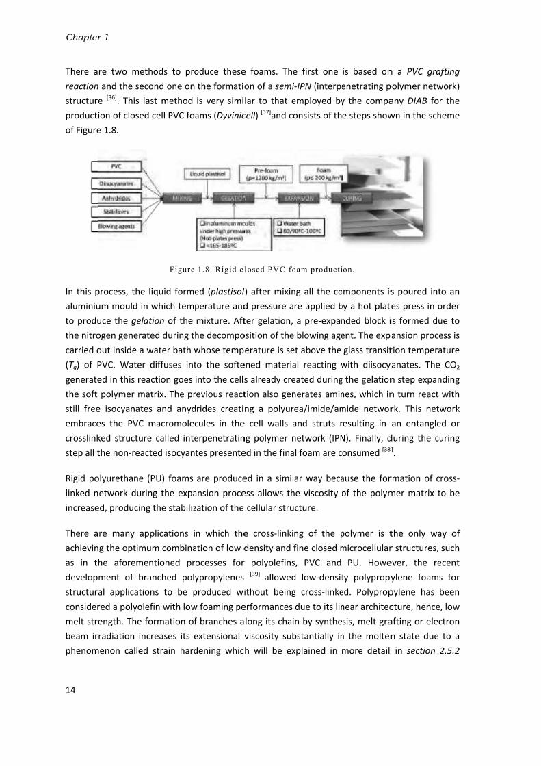
Chapter
14
There a
reaction
structur
product
of Figure
In this p
aluminiu
to produ
the nitro
carried o
(Tg) of P
generate
the soft
still free
embrace
crosslink
step all t
Rigid po
linked n
increase
There a
achievin
as in t
develop
structur
consider
melt str
beam ir
phenom
r 1
re two met
n and the sec
e [36]. This la
ion of closed
e 1.8.
process, the
um mould in
uce the gela
ogen generat
out inside a
PVC. Water
ed in this rea
polymer ma
e isocyanate
es the PVC
ked structur
the non-reac
olyurethane
network duri
ed, producing
are many ap
ng the optim
he aforeme
ment of br
al applicatio
red a polyole
ength. The f
rradiation in
menon called
thods to pro
cond one on
ast method
d cell PVC foa
Figure
liquid forme
n which temp
ation of the
ted during th
water bath w
diffuses int
action goes
atrix. The pr
es and anyd
macromolec
re called inte
cted isocyant
(PU) foams
ing the expa
g the stabiliz
pplications i
um combina
entioned pr
ranched poly
ons to be p
efin with low
formation of
creases its e
d strain hard
oduce these
the formatio
is very simi
ams (Dyvinic
1.8. Rigid cl
ed (plastisol
perature and
mixture. Aft
he decompo
whose temp
to the softe
into the cells
revious react
rides creati
cules in the
erpenetratin
tes presente
are produce
ansion proce
zation of the
n which the
ation of low d
ocesses for
ypropylenes
produced wi
w foaming pe
f branches a
extensional v
dening whic
e foams. The
on of a semi
lar to that e
cell) [37]and co
losed PVC fo
l) after mixin
d pressure a
ter gelation,
osition of the
erature is se
ened materia
s already cre
tion also gen
ng a polyur
e cell walls a
ng polymer n
ed in the fina
ed in a simil
ess allows th
cellular stru
e cross-linki
density and
r polyolefins
[39] allowed
ithout being
erformances
long its chai
viscosity sub
h will be ex
e first one
i-IPN (interpe
employed by
onsists of th
oam producti
ng all the co
re applied b
a pre-expan
e blowing age
et above the
al reacting w
eated during
nerates amin
rea/imide/am
and struts r
network (IPN
al foam are c
ar way beca
he viscosity o
ucture.
ng of the p
fine closed m
s, PVC and
d low-densit
g cross-linke
due to its lin
in by synthe
bstantially in
xplained in
is based on
enetrating p
y the compa
e steps show
on.
mponents is
by a hot plate
nded block i
ent. The expa
glass transit
with diisocya
g the gelation
nes, which in
mide networ
resulting in
N). Finally, d
onsumed [38]
ause the for
of the polym
polymer is t
microcellular
PU. Howe
ty polypropy
ed. Polyprop
near architec
sis, melt gra
n the molten
more detail
n a PVC graf
polymer netw
any DIAB for
wn in the sch
s poured int
es press in o
is formed du
ansion proce
tion tempera
anates. The
n step expan
n turn react
rk. This netw
an entangle
during the cu].
rmation of c
mer matrix t
the only wa
r structures,
ever, the re
ylene foams
pylene has
cture, hence
afting or elec
n state due
in section 2
afting
work)
r the
heme
to an
order
ue to
ess is
ature
CO2
nding
with
work
ed or
uring
ross-
to be
ay of
such
ecent
s for
been
, low
ctron
to a
2.5.2

Introduction
15
[40,41,42]. This phenomenon permits widen the range of densities for the production of non-
crosslinked polypropylene foams.
1.2.4- CellMat Laboratory research
This PhD thesis presents the investigations carried out at CellMat Laboratory facilities (University
of Valladolid) during the last four years in order to develop sustainable solid and foamed
materials for their application as food packaging trays and the core of sandwich panels. CellMat
Laboratory is a research group founded in 1999 by the Professor Dr. D Jose Antonio de Saja and
the Professor Dr. D. Miguel Ángel Rodríguez Pérez with the purpose of developing new scientific
knowledge in the area of Cellular Materials. At the beginning, it was focused on the structure-
properties relationship but as time went by several research lines were set up concerning the
development of advanced cellular materials. One of its aims is to provide the polymer foam
industry with new formulations and processes able to improve the current foamed products
found in the market and at the same time, contributing to create new scientific knowledge on
the foaming mechanisms involved in these processes and on the processing-structure-properties
relationship for these materials. The research lines currently addressed by CellMat Laboratory in
the area of polymer foams are shown in Figure 1.9. This PhD thesis is included in two of the
research topics: cellular nanocomposites and biopolymer based cellular
materials.[30,43,44,45,46,47,48,49,50,51,52,53,54]
Figure1.9.CellMat Laboratory research lines
Due to an increasing environmental awareness caused by the use of plastic materials one of the
research lines set up by CellMat Laboratory was the development of polymer foams based on
bioplastics and more sustainable polymers. In this sense, some of the scientific papers published
by the group in the recent years have dealt with this topic [30, 43-54]. Moreover, the research group
has been also involved in public-funded projects for the development of foams based on
sustainable polymers for food packaging, ACTIBIOPACK [55], or structural applications, NANCORE
Microcellular
materials
Cellular
nanocomposites
Biopolymer based
cellular materials
Nanocellular
materialsResearch lines
•Automotive.•Aeronautics.•Renewable Energies•Building
•Agriculture sector•Food-packaging•Biotechnology
Industrial sectors involved
•Developed in EEUU.• The scaling up finds difficulties in large-size pieces
•Lack of scientific knowledge in the interaction
nanoparticles -foaming mechanisms.
•Industrial scaling up still under development
•Technology under developmentCurrent status
•Automotive.•Aeronautics.•Renewable Energies•Building
•Very few precedents because it is a
newborn technology
•Automotive.•Aeronautics.•Renewable Energies•Building

Chapter
16
[56]. Mos
these tw
ACTIBIO
2011) co
packagin
describe
NAME
Bandesu
WP Divis
(WPDT)
Aragones
Lacas, S.A
Asociació
de la ind
(CITA)
Asociació
de la ind
(CTIC)
Riberebr
(RIBEREB
Profesion
(PROFEC
Universit
CellMat L
Universit
The gen
and film
mushroo
develop
product
r 1
st of the scie
wo projects a
Figure 1
1.2.4.1- Ac
OPACK was a
onstituted b
ng market. T
ed in Table 1
r Alcala S.A. (
sión Transform
sa de Tintas,
A. (ARTIBAL)
ón para la inv
ustria cárnica
ón para la inv
ustria cárnica
ro Integral S.A
BRO)
nales de la Ca
ARNE)
ty of Valladol
Laboratory.
ty of Zaragoza
eral purpose
ms with activ
oms. The Un
ment of fo
ion of solid
entific work d
and for this r
1.10.The rese
p
ctbiopack.
a research p
y a consorti
The organisa
.1.
(BANDESUR)
mados S.L.
Barnices Y
vestigación
a de La Rioja
vestigación
a de la Rioja
A.
arne
id (UVA).
a (UNIZAR)
T
e of this proj
ve compound
niversity of
ormulations
and foamed
developed in
eason, they
earch was con
projects:a)Ac
roject funde
um of public
tions involve
ORGANIZA
Private
Private
Private
Private
Private
Private
Private
Public
Public
Table 1.1.Ac
ject was the
ds to increa
Valladolid (C
based on
food-packag
n this thesis
are explaine
nducted in th
ctibiopack.b)
ed by the Sp
c research g
ed and their
ATION
T
A
s
s
s
s
t
Af
tibiopack co
developmen
se the shelf
CellMat Labo
biopolymers
ging trays. S
was also con
ed in more de
he framework
Nancore .
panish gover
roups and in
main roles w
ROLE
Trays develop
Films develop
Active coating
Mushrooms pscale.
Fresh meat pascale.
Mushrooms pscale.
Fresh meat pascale.
Research on btechniques fopackaging tra
Active compofor the packag
onsortium
nt of biodegr
-life of food
oratory) was
s and natu
Starch was ch
nducted in th
etail in the n
k of two rese
rnment (INN
ndustries rel
within the p
pment
pment
gs developme
packaging opti
ackaging optim
packaging opti
ackaging optim
bioplastics andor the productys.
ounds selectioges.
radable food
products su
s specifically
ral reinforc
hosen as the
he framewo
next sections
arch
NPACTO prog
ated to the
roject are br
ent
imization at a
mization at a
imization at a
mization at a
d foaming tion of food
on and safety t
d-packaging t
uch as meat
y focused on
cements for
e polymer m
ork of
.
gram
food
riefly
a lab
lab
a lab
lab
tests
trays
t and
n the
the
matrix

Introduction
17
because it is completely biodegradable and cheap in comparison with XPS, PET and PP, polymers
traditionally employed for the production of such trays.
Nevertheless, starch in the form of powder is a material which is difficult to process using
industrial plastic equipment such as presses, extruders and injection machines and for this
reason, it was plasticized with glycerol and/or water to turn it into thermoplastic starch (TPS) [57],
material with better processability and similar properties to those of thermoplastic petroleum-
based polymers. In spite of the similarities to other thermoplastics commonly employed for the
production of solid food-packaging trays such as PET and PP, TPS still represents a scientific
challenge for this application due to the fact that its mechanical properties are very dependent
on the degree of plasticization and on its hydrophilic character. Moreover, these properties
evolve with time because of ageing (crystallization) [58-61].[58,59,60,61]
Moreover, the replacement of XPS trays for TPS foamed trays seems to be very difficult because
they become very dry after foaming and thus, brittle. Food-packaging trays require certain
flexibility. For this reason, starch foams are more suitable for protective-packaging applications.
In this project, a new process was employed for the production of homogeneous starch foamed
blocks based on the interaction of water and microwave radiation. This process allowed a more
efficient and homogeneous heating of the samples to be produced, which results in more
homogeneous foams with regard to cellular structure. This work is explained in chapter 4 of this
thesis.
1.2.4.2- Nancore
Nancore was a project funded by the Seventh Framework Programme of the European Union
whose main goal was to develop novel microcellular nanocomposite foams able to be employed
as the core of sandwich panels for structural purposes, such as in the hull of yachts and in wind
turbine blades. Several public research organisations and industries around Europe were
involved in the project. They are listed in Table 1.2 together with their roles within the project.
NAME ORGANIZATION ROLE
LM Glass fiber A/S (Denmark) Private Requirement specification with regards to process, production and mechanical characteristics; demonstration and full scale testing; Consortium Management; integration of microcellular polymer nanocomposite (MNPC) into a sandwich structure.
Aalborg University (Denmark) Public Multi-scale modelling and simulations of microcellular nanocomposites; integration of MNPC into a sandwich structure; selection of functionalized components of polymer nanocomposites.
Recticel polyurethanes
(Belgium)
Private Development of PU formulations. Fabrication of PU foams on an industrial scale.
Katholieke Universiteit Leuven
(Belgium)
Public Rheological characterization of nanocomposites; multi-scale modelling and simulations of microcellular nano-composites; integration of MNPC into a sandwich structure.

Chapter
18
Universit
Universit
(Spain).
CellMat L
Azimut-B
Centre of
Macromo
(Poland)
Institute
Medicine
Technica
Denmark
EconCore
FOCAL lim
Kingdom
Sekisui A
The mat
and PVC
to its un
homoge
other ha
complex
compan
matrix is
makes t
Figure
The pro
polyuret
polyprop
r 1
tät Kassel (Ge
ty of Valladol
Laboratory.
Benetti S.P.A
f Molecular a
olecular Stud
of Occupatio
e (United King
al University o
k (Denmark)
e N.V. (Belgiu
mited (United
m)
Alveo AG (Swi
terials curre
C foams. Bals
nique structu
eneity in prop
and, present
x foaming t
ies around t
s cross-linke
his foam non
1.11. a) Cell
oject aimed
thane becau
pylene part
ermany) P
id P
. (Italy) P
and
ies
P
onal
gdom)
P
of P
um) P
d P
tzerland) P
ently employ
sa Wood is a
ure compose
perties is no
a high struc
technology
the world: D
ed in order t
n-recoverabl
lular structur
at developin
use they are
of the proje
Public
Public
Private
Public
Public
Private
Private
Private
Private
Table1.2. N
yed in the af
a natural cel
ed of highly e
t always gua
ctural homog
(briefly exp
DIAB [63] and
o obtain low
le by recyclin
re of Balsa W
ng new rigid
cost-effectiv
ect due to t
Industnanocfoame
Producscale
Requirintegrademon
Selectinanocprocessolids
Safetynanoc
Life Cy
Integra
Requirintegrademon
Producindust
Nancore cons
foremention
llular solid w
elongated ce
aranteed, du
geneity altho
plained in s
d 3A COMPO
w density fo
ng after end-
Wood [ 62 ] .b) C
d microcellu
ve materials
he fact that
rial proceomposites; m
ed sandwich p
ction and cha
rement specifation of MNnstration and
ion of functioomposites asses, producPP nanocomp
issues omposites
ycle Assessme
ation of MNPC
rement specifation of MNnstration and
ction of PP frial scale.
sortium.
ned applicati
with excellen
ells as shown
e to its natu
ough their pr
section 1.2.
OSITES [64]. In
ams with clo
-use [65].
ellular struct
ular foams b
s. This work
t this polyme
essing ofmechanical chanels
aracterization
fication with rPC into a safull-scale test
nalized compand elemention and ch
posites for foa
of nano
nt of new cor
C into a sandw
fication with rPC into a safull-scale test
foamed nano
ons are usu
nt mechanica
n in Figure 1.
ral origin. PV
rice is usually
3.2) only a
n addition, t
osed cellular
ture of a rigi
based on po
is focused e
er was non
f microceharacterizatio
n of foams at
regards to proandwich structing.
ponents of polnts of foaharacterizatioaming applicat
oparticles
re material
wich structure
regard to proandwich structing.
ocomposite o
ually Balsa W
al properties
.11 [62]. Howe
VC foams, on
y high becau
available at
the PVC poly
r structures.
d PVC foam
olypropylene
especially on
cross-linked
ellular on of
t lab-
ocess, cture;
ymer aming n of tions
from
e
ocess; cture;
on an
Wood
s due
ever,
n the
se of
two
ymer
This
[ 65 ] .
and
n the
and

Introduction
19
therefore, represents a sustainable alternative to cross-linked PVC foams. The work developed
with PU foams within this project can be found in a previous thesis of the group [66]. The
scientific and technical challenges of the project are connected to the inherent difficulties in
foaming polypropylene to low densities [4,40,41,42], the necessity of reinforcing it with
nanoparticles and the development of additional strategies with the aim of obtaining PP foams
with comparable mechanical properties to those based on PVC [67].

Chapter 1
20
1.3- Objectives
The main objective of this work is the development of production routes and solid and foamed
materials based on sustainable polymers that could contribute to mitigating the damage that
common synthetic polymers are causing in the environment. This is a common aim of all the
research performed but some other specific objectives were set regarding the specific
applications of each polymer: starch and polypropylene.
1.3.1- Starch
The use of starch as a biopolymer for the production of food-packaging trays and protective
packaging foams requires solving several challenges related to its poor foaming behaviour and
poor mechanical properties after being plasticized and foamed. One of the strategies that can be
adopted to increase the strength of TPS is the reinforcement with natural fillers, which seems in
principle the best choice due to their bioderived and biodegradable character and to their
chemical compatibility with starch. However, after revising the existing literature related to the
production and characterization of starch-based biocomposites (Section 2.3.2.2) and starch-
based foams (Section 2.4), it has been detected that there is a general lack of knowledge
concerning how natural fillers influence the foaming behaviour of starch and the final cellular
structures and mechanical properties obtained. As far as processing is concerned, there are few
studies dealing with the production of starch-based foams by microwave radiation for packaging
applications. Indeed, the reinforcement of these foams with natural fillers is a topic which has
not been addressed so far. Taking all these considerations into account several objectives were
established:
1. Developing biobased and biodegradable formulations based on thermoplastic starch
(TPS) and optimizing the lab-scale production routes such as thermoforming and
microwave foaming to obtain solid and foamed materials.
2. Improving the mechanical properties of solid and foamed TPS-based materials by the
reinforcement with natural fillers.
3. Studying the effect that natural fillers have on the mechanical properties of the
materials developed. In the case of foamed materials the analyses will be extended to
understanding their effect on foaming mechanisms and on the final cellular structures
obtained.
4. To analyse the structure-properties relationship in these materials.
5. Describing the mechanical results obtained by using analytical models found in literature
such as the cubic cell model of Gibson and Ashby [7].
6. Evaluating if the developed processing routes and formulations can be used to produce
food packaging trays and shaped-foams for protective packaging applications.

Introduction
21
1.3.2- Polypropylene
The use of PP foams for structural applications has always been restricted because of its poor
foamability and low mechanical properties. In spite of the recent improvements achieved in the
development of branched polypropylenes, the cellular structures and mechanical properties
obtained with these foams are still far from those of Balsa Wood and closed cell PVC foams. The
use of nanoclays, which in principle should have represented a promising strategy to solve these
matters, has not produced all the expected results so far. A revision of literature in this field
(section 2.5.3) showed us that there is still a lack of understanding of the processing-structure-
properties relationship in these heterogeneous foamed systems. This work aimed at solving
these challenges by setting the following objectives:
1. Developing formulations and optimizing the lab-scale production routes such as the
improved compression moulding route (ICM), a foaming process previously developed at
CellMat Laboratory [68] for the production of medium and low-density polypropylene
based foams.
2. Evaluating the influence that processing parameters such as pressure, temperature/time
and blowing agent content have on the cellular structure and hence, on the mechanical
properties of medium-density polypropylene foams.
3. Evaluating the influence of nanoclays on the cellular structure and mechanical
properties of low-density polypropylene based foams produced under different foaming
pressures.
4. To analyse the relationship structure-properties in these materials.
5. To use analytical models found in literature to describe the mechanical behaviour of the
rigid cellular materials obtained [69-71].[69,70,71]
6. To evaluate if the PP foams produced could replace cross-linked PVC foams as the core
of sandwich panels.

Chapter 1
22
1.4- Contents
This work is presented in the form of articles compendium. Three articles already published in
international journals and one more submitted for publication are presented. The general
structure of the work consisted of seven chapters in which the articles published are included.
Chapter 1. Introduction: the framework of the research is presented in this chapter, which
accounts for the environmental concerns caused by the huge increment of petroleum-based
plastics production and the strategies employed to mitigate them, all these aspects analysed
from the point of view of the polymer foam industry. Moreover, the specific objectives, the
contents of the work and the scientific articles and conferences derived from it are listed.
Chapter 2. Background and State of the art: this chapter deals with a revision of the main
concepts related to polymer foams, such as those derived from the cellular structure and
mechanical properties, and with a description of the most used analytical models found in
literature to explain their mechanical behaviour. Moreover, a description of the previous
works found in the field of starch-based biocomposites, nanocomposites, starch-based
foams and polypropylene-based foams have also been included.
Chapter 3. Materials, production methods and characterization techniques: the materials
employed in this work such as polymers, micro and nano-fillers and blowing agents will be
described. The production methods used will be presented and analysed. The use of
microwaves represents a promising way of transferring heat to a polymer matrix such as
starch in order to be foamed and the improved compression moulding route(ICM) is a
process developed in CellMat Laboratory in which the pressure applied to the molten
polymer and the use of self-expandable moulds plays a fundamental role for obtaining
varied cellular structures.
Chapter 4. Development of starch-based materials: in this chapter the research carried out
with starch isdescribed, which consists of two parts. The first one corresponds to the
research performed with solid biocomposites. A scientific article is included addressing the
research performed with TPS reinforced with natural fillers [72]. The second one deals with
the development of starch foamed blocks reinforced with natural fillers produced by
microwave radiation. The results are also shown by means of a published scientific article [73].
Chapter 5. Development of polypropylene foams: in this chapter the attention is focused on
the research developed with polypropylene foams produced by ICM. It is also split up into
two parts, the first one dedicated to medium-density polypropylene foams and the second
one to low-density polypropylene foams (<200 kg/m3) reinforced with nanoclays and
produced by varying the pressure applied to the molten polymer during foaming. The results
will be shown as well in the form of published or submitted articles to international scientific
journals [74,75].

Introduction
23
Chapter 6. Production of prototypes: all the previous research led to the development of
prototypes of food packaging trays and structural foamed panels. Due to the high industrial
applicability of this research, a chapter dealing with the methodology and main production
steps of each prototype are included. In the case of the PP foams the properties of the
foamed panels produced were found to be similar to those of foamed panels habitually used
in the market.
Chapter 7. Conclusions and Future work: although the results obtained increased the
knowledge in the field of starch and PP-based foams, some questions have not yet been
answered and some others arise from them. Currently, new research lines are under
development in the group with regards to these topics. This chapter summarizes the main
conclusions obtained and the future work.

Chapter 1
24
1.5- Publications and Conferences
The work developed during this thesis resulted in the publication of several scientific articles,
some of which have already been published in international journals and others have been
submitted. They are listed in table 1.3. The section in which the articles are included is specified
in the third column. Some of the works appearing in this table were not included in this thesis in
spite of being related to the fields studied.
Starch-based materials. Section
1 Almidón termoplástico celular reforzado con fibras naturales. Una opción
bioderivada y biodegradable para el envasado de alimentos. López-Gil, A.; Bellucci, F.S.; Ardanuy, M.; Rodríguez-Pérez, M.A.; de Saja, J.A. Revista de plásticos modernos. Num. 671. January 2013.
-
2 Strategies to improve the mechanical properties of starch-based materials:
plasticization and natural fibres reinforcement. López-Gil, A.; Bellucci, F.S.; Ardanuy, M.; Rodríguez-Pérez, M.A.; de Saja, J.A. Polímeros. Ciência e Tecnologia. vol. 24, n. Especial, 36-42. 2014.
4.2
3 Cellular structure and mechanical properties of starch-based foamed blocks
reinforced with natural fibres and produced by microwave heating. Lopez-Gil A., Silva-Bellucci, F., Velasco D., Ardanuy, M., Rodriguez-Perez, M.A. Industrial Crops and
Products. 66, 194–205. 2015.
4.3
Polypropylene-based materials. Section
1 Structure property relationships of medium-density polypropylene foams. Saiz-Arroyo, C.; Rodríguez-Pérez, M.A.; Tirado, J.; López-Gil, A.; de Saja, J.A.; Polymer
International. 62, 1324-1333. 2013. -
2 Production of non-crosslinked thermoplastic foams with a controlled density and a
wide range of cellular structures. Lopez-Gil, A.; Saiz-Arroyo, C.; Tirado, J.; Rodríguez-Pérez, M.A. Journal of Applied Polymer Science. 132, 2015.
5.2
3 Anisotropic polypropylene cellular polymers filled with nanoclays: microstructure
and properties. Lopez-Gil, A.; Benanti, M.; Lopez-Gonzalez, E.; Ruiz-Herrero, J.L.; Briatico, F.; Rodriguez-Perez, M.A. Submitted.
5.3
Table1.3. Scientific articles

Introduction
25
In addition, this work was presented in national and international conferences. These
presentations are included in Table 1.4.
Starch-based materials.
1 Mechanical properties of biocomposites based on thermoplastic starch and cellulosic fibres from
agricultural residues. Ardanuy, M.; Algaba, I.; García-Hortal, J.A.; López-Gil, A.; Rodríguez-Pérez, M.A. 4th International Textiles Congress. Istanbul, Turkey. 16-18 May. 2010. Oral.
2 Development of starch biobased and biodegradable plastics for their use in trays for food-
packaging. López-Gil, A.; Rodríguez-Pérez M.A.; de Saja, J.A.; Bellucci, F.S.; Ardanuy. M.EUROTEC 2011. Barcelona. Spain. 14-15 November2011. Oral.
3 Productos bioderivados y biodegradables de bajo coste basados en almidón. Aplicación en
bandejas para alimentación. López-Gil, A.; Rodríguez-Pérez, M.A.; de Saja, J.A.; V Jornadas de Innovación y Tecnología Alimentaria CTIC-CITA. Calahorra, Spain. April 25th 2012. Oral.
4 Development of low density starch-biobased and biodegradable plastics reinforced with natural
fibers. López-Gil, A.; Silva-Bellucci F.; Ardanuy, M.; Rodríguez-Pérez, M.A.; de Saja, J.A. XI Brazilian MRS Meeting (SBP mat). Florianópolis, Brazil. September 27th 2012.Oral.
Polypropylene-based materials.
1 Multi-level characterization of the compressive behaviour of novel cellular nanocomposites.
Shishkina, O.; Zhu, Y.; Escudero, J.; Lopez-Gil, A.; Rodriguez Perez, M.A.; Gorbatikh, L.; Lomov, S.V.; Verpoest, I. European Conference on Composite Materials. ECCM15. Venice, Italy 24-28 June 2012. Oral.
2 Production of non-crosslinked polyolefin foams with controlled density and tailored cellular
structure and physical properties. Saiz-Arroyo, C.; Escudero, J.; López-Gil, A.; Rodríguez-Pérez, M.A. 10th International Conference on Foams and Foams Technology. FOAMS 2012. Barcelona, Spain.12-13 September 2012. Oral.
3 Nano-strategies applied to the production of cellular polymers with improved cellular structure
and properties. Rodríguez-Pérez, M.A.; Pardo-Alonso, S.; Estravis, S.; Saiz-Arroyo, C.; Solorzano-Quijano, E.; Escudero-Arconada, J.; Pinto-Sanz J.; López-Gil, A.; Rodríguez-Pérez, M.A. CellMat Conference. Dresden, Germany. November 2012. Key-note lecture.
4 Understanding the foamability of polypropylene blends and polypropylene nanocomposites by
using extensional rheology. Laguna-Gutiérrez, E.; Escudero, J.; López-Gil, A.; Rodríguez-Pérez, M.A.; AERC, 8thAnnualEuropeanRheologyConference. Leuven, Belgium. April 2-5 2013. Oral.
5 AniCell. Low density and non-crosslinked polypropylene foams as a promising option to produce
structural panels. López-Gil, A.; Escudero, J.; Laguna-Gutiérrez, E.; Saiz-Arroyo, C.; Rodríguez-Pérez, M.A.EUROTEC 2013. Lyon, France. July5th2013. Oral.
6 Production and cellular structure characterization of polypropylene foams: influence of the chain
arquitecture, density and blowing agent. Salmazo, L.O.; Bellucci, F.S.; López-Gil, A.; Rodríguez-Pérez, M.A.; Job, A.E.XIII Encontro SBP Mat. João Pessoa, Brazil. 2014. Oral.
7 Extensional rheology: a tool to predict the foamability of complex systems such as polymer blends
and recycled polymers. Laguna-Gutiérrez, E.; López-Gil, A.; Saiz-Arroyo, C.; Rodríguez-Pérez, M.A. FOAMS 2014. September 10-11 2014. New Jersey, United States. Oral.
Table 1.4. Scientific conferences

Chapter 1
26
Finally, Table 1.5 shows additional activities developed during this thesis related to other
materials, such as natural rubber foams, and research stays, contributions in books and patents.
Scientific articles and conferences.
1 Natural rubber foams with anisotropic cellular structures: mechanical properties and modelling.
Salmazo, L.O.; López-Gil, A.; Silva-Bellucci, F.; Job, A.E.; Rodríguez-Pérez, M.A. Industrial Crops and
Products. Submitted
2 Study of the concentration of ZnO in the production of vulcanized natural rubber foams. Salmazo, L.O.; Bellucci, F.S.; Lopez-Gil, A.; Rodriguez-Perez, M.A.; Job, A.E. XI Encontro da SBP Mat-Brazilian MRS meeting. Florianópolis, Brazil. September 27th 2012. Poster.
2 Mechanical compression tests of multifunctional vulcanized natural rubber nanocomposites.
Bellucci, F.S.; Salmazo, L.O.; Lopez-Gil, A.; Budemberg, E.R.; Nobre, M.A.L.; Rodriguez-Perez, M.A.; Job, A.E. XII Brazilian MRS Meeting –SBP Mat .2013. Campos do Jordão, Brazil. Poster.
3 Cellular structure and mechanical properties of foams based on natural rubber and natural
rubber/styrene butadiene rubber blends. Salmazo, L.O.; Bellucci, F.S.; López-Gil, A.; Rodríguez-Perez, M.A.; Job, A.E.XII Brazilian MRS Meeting-SBPMat. 2013. Campos do Jordão, Brazil. Poster.
4 Estudo das propriedades morfológicas, estruturais e acústicas de espumas de borracha natural.
Salmazo, L.O.; Bellucci, F.S.; López-Gil, A.; Rodríguez-Pérez, M.A.; Job, A.E. 12 Congresso Brasileiro de Polímeros - CBPOL. 2013. Florianópolis. Brazil. Poster.
5 Correlation between mechanical properties and cellular structure of medium-density natural
rubber foams with different anisotropy ratios. Salmazo, L.O.; Bellucci, F.S.; López-Gil, A.; Rodriguez-Perez, M.A.; Job, A.E.XIII EncontroSBPMat.2014. João Pessoa, Brazil. Poster.
Research stays.
1 Universidade Estadual Paulista (UNESP). Presidente Prudente. Brazil. July-October 2012.
2 Universidade Federal do ABC(UFABC).São Paulo. Brazil. 6-10 August 2012.
Contribution in books.
1 Natural Rubber Materials. Volume 2: Composites and Nanocomposites. Chapter 26: applications
of natural rubber composites and nanocomposites. Job, A.E.; Cabrera, F.C.; Oliveira-Salmazo, L.; Rodriguez-Perez, M.A.; Lopez-Gil, A.; De Siqueira, A.F. and Bellucci, F.S.DOI:10.1039/9781849737654.
Patents. Chapter
1 Method for producing cellular materials having a thermoplastic matrix. Miguel Angel Rodriguez Perez, José Antonio de Saja Saez, Javier Escudero Arconada, Alberto López Gil. Patent number: WO2014/009579 A1. 12.01.2014
Annex
Table1.5. Additional activities

Introduction
27
References
[1] Eduardo, P. Y. Química Orgánica básica y aplicada. Editorial Reverté. S.A. 1995.
[2] Plastic Europe. Association of Plastic Manufacturers. www.plasticseurope.es.
[3] Lee, S.T.; Park, C.B. and Ramesh, N.S. Polymeric Foams. Science and Technology. Taylor and Francis
Group.2007.
[4] Klempner, D. and Frisch, K.C. Handbook of polymeric foams and foam technology. Hanser
Publishers.1991.
[5] www.bccresearch.com/market-research/plastics/polymeric-foams-pls008g.html
[6] Löffler, A. and Däschlein, C. The future of polymer foams. A matter of sustainability. BASF. The
Chemical Company. Polymer Foam 2014.Cologne-Germany. 2-4 November 2014.
[7] Gibson, L.J. and Ashby, M.F. Cellular solids: Structure and properties. 2nd ed. Cambridge: UK, Cambridge University Press, 1997.
[8] Singh, B. and Sharma, N. Mechanistic implications of plastic degradation. Polymer Degradation and
Stability. 93, 561-584. 2008.
[9] Shah, A.A.; Hasan, F.; Hameed, A. and Ahmed, S. Biological degradation of plastics: A comprehensive review. Biotechnology Advances. 26, 246-265. 2008.
[10] Andrady, A.L. Microplastics in the marine environment. Marine Pollution Bulletin. 62, 1596-1605. 2011.
[11] Moore, C.J. Synthetic polymers in the marine environment: A rapidly increasing, long-term threat. Environmental Research. 108, 131-139. 2008.
[12] Davis, G. and Song. J.H. Biodegradable packaging based on raw materials from crops and their impact on waste management. Industrial Crops and Products. 23, 147-161. 2006.
[13] Hamad, K.; Kaseem, M. and Deri, F. Recycling of waste from polymer materials: An overview of the recent works. Polymer Degradation and Stability. 98, 2801-2812. 2013.
[14] http://europa.eu/legislation_summaries/environment/waste_management/index_en.htm
[15] http://en.european-bioplastics.org
[16] Chanprateep S. Current trends in biodegradable polyhydroxyalkanoates. Journal of Bioscience and
Bioengineering.110, 621–632, 2010.
[17] Nampoothiri, K.M.; Nair, N.R. and John, R.P. An overview of the recent developments in polylactide (PLA) research. Bioresource Technology. 101. 8493-8501. 2010.
[18] James, B. and Roy, W. Starch: Chemistry and Technology.3th ed. Elsevier.2009.
[19] Bertolini, A.C. Starches. Characterization, properties and applications. Taylor and Francis
Group.2010.
[20] Kalia, S.; Kaith, B.S. and Kaur, l. Cellulose fibers: bio and nano-polymer composite. Springer.2011.
[21] http://www.natureworksllc.com/
[22] http://www.braskem.com.br/site.aspx/plasticoverde
[23] http://www.cocacola.es/compromiso/medio-ambiente/envases-sostenibles#.VGkE8fmG8mt
[24] http://www.coopbox.it/portal/page?_pageid=896,6266577&_dad=portal&_schema=PORTAL
[25] Zhang, Y.; Broekhuis, A.A. and Picchioni, F. Thermally self-healing polymeric materials: the next step to recycling thermoset polymers. Macromolecules. 42, 1906-1912. 2009.
[26] Pickering, S.J. Recycling technologies for thermoset composite materials-current status. Composites: Part A. 37, 1206-1215. 2006.
[27] Rodriguez-Perez, M.A. Crosslinked polyolefin foams: Production, structure, properties and applications. Advances in Polymer Science. 184, 97-126. 2005.

Chapter 1
28
[28] Rodriguez-Perez, M.A. Propiedades térmicas y mecánicas de espumas de poliolefinas. Tesis
doctoral. Universidad de Valladolid. España.1998.
[29] Tamboli, S.M.; Mhaske, S.T. and Kale, D.D. Properties of high-density polyethylene filled with waste crosslinked foam. Journal of Applied Polymer Science. 91,110–114. 2004.
[30] Saiz-Arroyo, C.; de Saja, J.A. and Rodríguez-Pérez. M.A. Production and characterization of crosslinked low-density polyethylene foams using waste of foams with the same composition. Polymer Engineering and Science. 52, 751-759. 2012.
[31] http://www.trocellen.com./
[32] http://www.sekisuialveo.com/nc/es/pagina-de-inicio.html
[33 http://www.okcompanysa.com./
[34] http://www.palziv.com/
[35] http://www.zotefoams.com/
[36] Jiang, Z.; Yao, K.; Dua, Z.; Xue, J.; Tang T. and Liu, W. Rigid cross-linked PVC foams with high shear properties: the relationship between mechanical properties and chemical structure of the matrix. Composites Science and Technology. 97, 74-80. 2014.
[37] http://www.diabgroup.com/en-GB/Products-and-services.
[38] Danielsson, M. and Grenestedt. J.L. Gradient foam core materials for sandwich structures: preparation and characterization. Composites Part A.29, 981-988. 1998.
[39] http://www.borealisgroup.com/en/polyolefins/new-business-development/Foam-and-HMS/
[40] Spitael, P. and Macosko.C.W. Strain hardening in polypropylenes and its role in extrusion foaming. Polymer Engineering and Science. 44, 2090-2100. 2004.
[41] Stange J. and Münstedt, H. Rheological properties and foaming behaviour of polypropylenes with different molecular structures. Journal of Rheology.50, 907-923. 2006.
[42] Gotsis, A.D. and Zeevenhoven, B.L.F. Effect of long branches on the rheology of polypropylene. Journal of Rheology. 48, 895-914. 2004.
[43] Obeso, C.G.; Song, W.; Rodríguez-Pérez, M.A. and Mano, J.F. Superhydrophobic to super hydrophylic biomimetic poly(3-Hydroxybutyrate) surfaces made by phase inversion. Materials
Science Forum. 730-732,44-49. 2013.
[44] Obeso, C.G.; Sousa, M.P.; Song, W.; Rodriguez-Pérez, M.A.; Bhushand, B. and Mano, J.F. Modification of paper using polyhydroxybutyrate to obtain biomimetic super hydrophobic substrates. Colloids and Surfaces A: Physicochemical and Engineering Aspects. 416, 51–55.2013.
[45] Bellucci, F.S.; Salmazo, L.O.; Budemberg, E. R.; da Silva, M.R.; Rodríguez-Pérez, M.A.; Nobre, M.A.L. and Job, A.E. Preparation and structural characterization of vulcanized natural rubber nanocomposites containing nickel-zinc ferrite nanopowders. Journal of Nanoscience and
Nanotechnology. 12, 2691-2699. 2012.
[46] Rodriguez-Perez, M.A.; Simoes, R.D.; Roman-Lorza, S.; Alvarez-Lainez, M.; Montoya-Mesa, C.; Constantino, C.J.L.; de Saja. J.A. Foaming of EVA/Starch Blends: Characterization of the structure, physical properties, and biodegradability. Polymer Engineering & Science.52, 62-70. 2012.
[47] Rodriguez-Perez, M.A.; Simoes, R.D.; Constantino, C.J.L. and de Saja. J.A. Structure and physical Properties of EVA/Starch precursor materials for foaming applications. Journal of Applied Polymer
Science.121, 2324-2330. 2011.
[48] Simões, R.D.; Rodriguez-Perez, M.A.; de Saja, J.A. and Constantino, C.J.L. Thermo mechanical characterization of PVDF and P(VDF-TrFE) blends containing corn starch and natural rubber. Journal
of Thermal Analysis and Calorimetry. 99, 621-629. 2010.
[49] Simões, R.D.; Rodriguez-Perez, M.A.; de Saja, J.A.; Constantino, C.J.L. Tailoring the structural properties of PVDF and P(VDF-TrFE) by using natural polymers as additives. Polymer Engineering &
Science. 49, 2150-2157. 2009.

Introduction
29
[50] Ghosh, S.; Gutierrez, V.; Fernandez, C.; Rodriguez-Perez, M.A.; Viana, J.C. Reis, R.L.; Mano, J.F. Dynamic mechanical behaviour of starch-based scaffolds in dry and physiologically simulated conditions: Effect of porosity and pore size. ActaBiomaterialia. 4, 950-959. 2008.
[51] Saiz-Arroyo, C.; Wang, Y.; Rodriguez-Perez, M.A.; Alves, M.; Mano, J.F. In vitro monitoring of surface mechanical properties of poly(L-Lactic Acid) using microhardness. Journal of Applied
Polymer Science, 105, 3858-3864. 2007.
[52] Prabaharan, M.; Rodriguez-Perez, M.A.; de Saja, J.A.; Mano, J.F. Preparation and characterization of poly(L-lactic acid)-chitosan hybrid scaffolds with drug release capability. Journal of Biomedical
Materials Research Part B: Applied Biomaterials. 81, 427-434. 2007.
[53] Alves, N.M.; Saiz-Arroyo, C.; Rodriguez-Perez , M.A.; Reis, R.L.; Mano, J.F. Microhardness of starch based biomaterials in simulated physiological conditions. ActaBiomaterialia. 3, 69-76. 2007.
[54] Wang, Y.; Rodriguez-Perez, M.A.; Reis, R.L.; Mano. J.F. Thermal and thermo mechanical behaviour of polycaprolactone and starch/polycaprolactone blends for biomedical applications. Macromolecular Materials and Engineering. 290, 792-801. 2005.
[55] http://clusterfoodmasi.es/proyectos/actibiopack.
[56] http://cordis.europa.eu/result/rcn/45930_en.html.
[57] Leon, J. and Leszek, M. Thermoplastic starch. A green material for various industries.Wiley-
VCH.2009.
[58] Avérous, L.; Fringant, C. and Moro, L. Starch-based biodegradable materials suitable for thermoforming packaging. Starch/Stärke. 53, 368-371. 2001.
[59] Hulleman, S.H.D.; Janssen, F.H.P.; and Feii, H. The role of water during plasticization of native starches.Polymer.39. 2043-2048. 1998.
[60] Myllärinen, P.; Partaken, R.; Seppälä, J. and Forssella, P. Effect of glycerol on behaviour of amylose and amylopectin films. Carbohydrate Polymers. 50, 355-361. 2002.
[61] Van Soest, J.J.G.; Hulleman, S.H.D.; De Wit, D. and Vliegenthart, J.F.G. Changes in the mechanical properties of thermoplastic potato starch in relation with changes in B-type crystallinity. Carbohydrate Polymers. 29, 225-232. 1996.
[62] Shishkina, O.; Lomov, S.V.; Verpoest, I. and Gorbatikh, L. Structure–property relations for balsa wood as a function of density: modelling approach. Archive of Applied Mechanics. 84, 789-805, 2014.
[63] http://www.diabgroup.com.
[64] http://www.3acomposites.com.
[65] Jiang, Z.; Yao, K.; Du, Z.; Xue, J.; Tang, T. and Liu, W. Rigid cross-linked PVC foams with high shear properties: the relationship between mechanical properties and chemical structure of the matrix. Composites Science and Technology. 97, 74-80. 2014.
[66] Estravís, S. Cellular nanocomposites based on rigid polyurethane and nanoclays: Fabrication, characterization and modelling of the mechanical properties and thermal properties. PhD Thesis. University of Valladolid. Spain. 2014.
[67] Lee, L.J.; Zeng, C.; Cao, X.; Han, X.; Shen, J. and Xu, G. Polymer nanocomposite foams. Composites
Science and Technology. 65, 2344-2363. 2005.
[68] Saiz-Arroyo, C.; Rodriguez-Perez, M.A.; Tirado, J.; Lopez-Gil, A. and de Saja, J.A. Structure-property relationships of medium-density polypropylene foams. Polymer International. 62, 1324-1333. 2013.
[69] Huber, A.T. and Gibson L.J. Anisotropy of polymer foams. Journal of Materials Science. 23, 3031-3040. 1988.
[70] Sullivan, R.M.; Ghosn, L.J. and Lerch, B.A.A. General tetrakaidecahedron model for open-celled foams. International Journal of Solids and Structures. 45, 1754-1765. 2008.

Chapter 1
30
[71] Sullivan, R.M.; and Ghosn, L.J. Shear moduli for non-isotropic, open cell foams using a general elongated Kelvin foam model. International Journal of Engineering Science. 47, 990-1001. 2009.
[72] Lopez-Gil, A.; Bellucci, F.S.; Ardanuy, M.; Rodriguez-Perez, M.A. and de Saja, J.A. Strategies to improve the mechanical properties of starch-based materials: plasticization and natural fibres reinforcement. Polímeros: Ciência e Tecnologia. 24, 36-42. 2014.
[73] Lopez-Gil, A.; Bellucci, F.S.; Velasco, D.; Ardanuy, M.; Rodriguez-Perez, M.A. Cellular structure and mechanical properties of starch-based foamed blocks reinforced with natural fibres and produced by microwave heating. Industrial Crops and Products. 66, 194-205. 2015.
[74] Lopez-Gil, A.; Saiz-Arroyo, C.; Tirado, J.; Rodriguez-Perez, M.A. Production of non-crosslinked thermoplastic foams with a controlled density and a wide range of cellular structures. Journal of
Applied Polymer Science. 132, 42324.2015.
[75] Lopez-Gil, A.; Benanti, M.; Lopez-Gonzalez, E.; Ruiz-Herrero J.L.; Briatico, F.; Rodriguez-Perez, M.A. Anisotropic polypropylene foams filled with nanoclays: microstructure and properties. Submitted. 2015.

CHAPTER 2:
BACKGROUND AND STATE OF THE ART


Contents
2.1‐ Introduction .................................................................................................................. 35 2.2‐ Cellular materials .......................................................................................................... 36 2.3‐ Polymer foams: fundamentals of foaming ...................................................................... 37 2.4‐ Cellular structure‐mechanical properties relationship in polymer foams ......................... 41
2.4.1‐ Improving the cellular structure: the role of Anisotropy ............................................. 46 2.4.1.1‐ Rectangular cell model ..................................................................................... 47 2.4.1.2‐ Tetrakaidecahedron cell model ......................................................................... 49
2.4.2‐ Reinforcement with fillers: polymer composites ....................................................... 51 2.4.2.1‐ Natural fibres ................................................................................................... 52 2.4.2.2‐ Starch‐based biocomposites ............................................................................. 54 2.4.2.3‐ Polymer nanonocomposites: nanoclays ............................................................. 62
2.5‐ Starch‐based foams ....................................................................................................... 67 2.5.1‐ Starch foaming processes ........................................................................................ 70
2.5.1.1‐ Extrusion foaming ............................................................................................ 70 2.5.1.2‐ Baking ............................................................................................................. 71 2.5.1.3‐ Microwave foaming .......................................................................................... 72
2.5.2‐ Starch foams reinforced with natural fibres .............................................................. 75 2.5.3‐ Summary ................................................................................................................ 77
2.6‐ Polypropylene‐based foams .......................................................................................... 79 2.6.1‐ Polypropylene foaming processes ............................................................................ 80
2.6.1.1‐ Extrusion foaming ............................................................................................ 80 2.6.1.2‐ Compression moulding ..................................................................................... 81 2.6.1.3‐ Moulded‐bead process ..................................................................................... 83
2.6.2‐ Polypropylene foams in the market: development of branched polypropylenes .......... 84 2.6.3‐ Foamed polypropylene nanocomposites .................................................................. 85 2.6.4‐ Practical use of polypropylene foams as the core of sandwich panels ......................... 86 2.6.5‐ Summary ................................................................................................................ 88

Chapter 2
34

Background and State of the Art
35
2.1‐ Introduction
This chapter deals with the revision of the main concepts related to cellular materials (section 2.2) being more focused on those specifically used for polymer foams (section 2.3). The sustainable foams developed in this thesis, based on biodegradable thermoplastic starch and non‐crosslinked polypropylene, belong to this family of cellular materials. The principal mechanisms constituting a foaming process (nucleation, expansion and stabilization) will be also dealt with in section 2.3. Among them, the stabilization of the cellular structure will receive special attention because its understanding is a key factor for the production of starch‐based foams by microwave radiation (chapter 4). Section 2.4 will address the relationship between cellular structure and mechanical properties in polymer foams focusing the subject on the mechanical behaviour of anisotropic cellular structures. This issue will be treated specifically in chapter 5 because some of the PP‐based foams produced in this thesis present this particular structure. The reinforcement of the polymer matrix with fillers was a common strategy employed throughout the thesis in order to increase the mechanical properties of solid and foamed materials. Section 2.4.2 will address the main concepts related to the production of starch‐based biocomposites reinforced with natural fibres and to the production of polymer nanocomposites reinforced with nanoclays. Finally, in sections 2.5 and 2.6 an exhaustive revision of the works found in literature dealing with the production of solid and foamed starch‐based materials and the production of polypropylene foams is included. This revision was of paramount importance in order to settle the objectives of the thesis, which were listed in chapter 1.

Chapter
36
2.2‐ Cell
Cellular everywh
applicat
two diff
reductio
in appli
insulatio
be used from an
reduce w
These k
honeyco
several usually eratio is cit: high‐(ρf/ρs<0.
solids(Fi
cells in speriodic array (Fi
without
Figure
r 2
lular materia
materials ha
here: within ions. They aferent phase
on of density
ications in on are requir
in buoyancy
n economica
weight and in
kinds of ma
ombs, marine
criteria. Den
expressed as
called relativ‐density (ρf/ρ.2). High‐de
gure 2.1a).A
space. There
c cellular soliigure 2.1b). hierarchy in
2.1. Differen
als
ave become house walls
re called cel
es: a solid p
y and a wide
which for i
red. Moreov
y application
l and enviro
n this way, c
aterials are e organisms nsity (ρ) is o
s the ratio be
ve density (ρ/ρs 0.7), med
ensity cellul
Another crite
e are two opt
id because h
On the othe
n a three‐dim
nt kinds of ce
a fundamen
, inside car slular materia
phase and a
ening of the nstance, hig
ver, the inhe
s. Last but nonmental po
ut down on
found in na
etc. or are pone of them
etween the dρf/ρs) and the
dium‐density
ar material
erion used totions: period
hexagonal ce
er hand, in ramensional arr
ellular solids
c)Rando
ntal part of oseats and in als or "cellul
a gaseous p
solid proper
gh energy rent reducti
not least, red
oint of view raw materia
ature such produced by m. In the ca
density of there are three
y (0.7>ρf/ρs
ls are mor
o classify the
dic or random
ells are peri
andom celluray (Figure 2
s. a) Porous s
om ceramic fo
our daily live
food‐packag
ar solids" be
phase. This c
rties that ma
absorption on of densit
ducing densit
because the
als and costs
as in wood
men. They cse of cellula
e foam (ρf) ae kinds of ce
0.2) and lo
e frequentl
em is connec
m. A honeyco
odically orga
ular solids po
.1c).
solid. b) Peri
oam.
es because wging trays toecause they acombination
akes cellular in impacts y allows cell
ty is a key iss
ey are const[1].
d, corals, co
can be classif
ar materials and that of tellular mater
ow‐density c
y denomina
cted with the
omb is a typi
anised in a t
olyhedron ce
odic alumini
we can find to name but aare compose
n brings abo
r materials uand/or the
lular materia
sue for indus
tantly strivin
ork, tree tru
fied accordin
this proper
he solid (ρs).
rials accordin
cellular mate
ated as poe organizatio
ical example
two‐dimens
ells are organ
ium honeyco
them a few ed of out a seful
ermal als to stries ng to
unks, ng to rty is . This ng to erials orous on of e of a ional nised
mb.

2.3‐
The the molt
mat
all poly
misc
surr
to fothe by in
Onc
inte
cell fedge
inte
The also
poly
the Whe
foam
tem
the ratio
Whe
freq
Polymer foa
three‐dime
production pten materia
erials obtain
of which a
ymer/blowing
cible. Second
rounding con
orm spherica
molten phas
ncreasing the
e the foam
rconnected foams. In cles and walls rconnected f
classificatio
classified in
ymers. In thi
family of po
en they mel
ms. Instead,
perature/tim
rheological bo (ER) is def
en ER is ve
quent which
ams: fundam
nsional rand
process. Cell
l. This prod
ned from it aare schema
g agent systdly, cells nucnditions (pre
al nuclei. Thi
se to the inte
e melt streng
m is stable, resulting in losed cell foaenclosing thforming a co
ns described
n terms of t
s work the tolymer foam
t they do n
, they beco
me foaming behaviour of
fined as the ry high (ab
results in cel
mentals of fo
dom structur
ls are formed
uction meth
are called fotically show
tem in which
cleation, whi
ssure and/o
irdly, the experior of the cgth up to sol
Figur
the gas ph
a new classi
ams the solid
he gaseous pontinuous ga
d previously
he material thermoplast
s. Polymers ot become
ome a visco
window. Ho
f the polyme
ratio betwe
ove four tim
ll wall sharin
oaming
re of some cd after the ahod is usua
ams. A foam
wn in Figur
h both phase
ch is a respo
or temperatu
pansion of thcells, and finlidification [2
re 2.2.Foami
hase can b
fication of cd material in
phase inside. s phase [1,2].
are based oconstituting
ic starch and
are materia
a liquid suc
ous fluid, w
owever, this er and on the
een the dens
mes) the co
ng (Figure 2.3
B
cellular mate
anarchic disp
lly referred ming process
re 2.2: firs
es, gas and onse of gas mure) that invo
he molten mally, the stab
2].
ng stages.
e isolated ellular mate
n each cell iOn the cont
on the struct
g the solid p
d polypropy
als with uniq
ch as in soap
which is mo
stability is lie expansion sity of the sontact betwe
3) [2].
ackground a
erials is a di
persion of ga
to as foam can be split
t of all, t
molten mate
molecules toolves their d
material due tbilization of t
in specific d
rials: closed s distributed
trary, in open
tures obtaine
phase: metal
lene foams due features p foams (Fig
ore stable mited in timratio of the folid and tha
een neighbo
and State o
rect conseq
as molecules
ming and the
t up in sever
he formatio
erial, are co
owards the cdiffusion into
to gas diffus
the cellular s
domains or
cell foams ad along the vn cell foams,
ed but foam
ls, ceramics,
developed bin the molt
gure 2.3) or and has a
me and it dep
foam. The ex
at of the foa
ouring cells
of the Art
37
uence of within a
e cellular ral steps, on of a mpletely
change in o clusters sion from structure
can be and open vertexes, cells are
ms can be glass or
belong to en state. metallic broader
pends on xpansion
am: ρs/ρf. is more

Chapter
38
Cell wal
which iscould be
the edge
soap an
polymer
molten macrosc
of the mturn lea
phenom
produce
smaller This res
smaller
The stab
adverse classifica
expansio
Figure
*The word
the cell siz
r 2
Figure 2.3.E
ll sharing is s mainly cau
e microscopi
es and verte
d metallic for foams the
polymer. Dcopic density
molten polym
ds to cell w
menon is cal
ed between to the large
ults in dege
cells.
bilization of effects ca
ation of pol
on. This class
e 2.4.Classifi
d degeneration
ze distribution.
volution of c
the phenom
sed by three
ically describ
xes due to coams becaus
extent to w
Drainage can
y gradients amer, either mwall rupture
led coalescetwo adjacen
r cells throu
nerated cell
the cellular
aused by th
lymer foams
sification is s
ication of po
is used here to
cells during f
menon that e mechanism
bed as the trcapillary forcse they have
which this ph
n also be i
along the foa
micro or macr
and the join
ence. Finally
nt cells, whic
gh the molt
ular structur
r structure is
he degener
s arises from
shown in Figu
lymer foams
duri
o describe all th
foam expansi
triggers the
ms: drainageansport of tces. It is a ph
e lower visco
henomenon induced by am. The mai
roscopically,
ning of the t
y, coarseningch creates t
en material res compose
s necessary ration mech
m how the
ure 2.4.
s based on the
ing foaming.
he processes th
ion and analo
degeneratio
e, coalescenche molten penomenon w
osities in the
occurs depe
gravity forin conseque
is the thinn
two cells sha
g is the resu
he diffusion
constituting
ed of large c
in any foam
hanisms pre
cellular stru
e stabilizatio
at cause an inc
ogy with a so
on* of the c
ce and coarsolymer from
which is mor
molten stat
ends on the
rces produci
nce of an ex
ing of the ce
aring the ce
ult of a pre
of gas mo
g cell walls, ecells surroun
ming process
eviously des
ucture becom
on mechanism
rease of cell siz
oap foam.
cellular struc
sening. Drainm the cell wa
re pronounce
te. In the ca
e viscosity of
ing in this xcessive drai
ell walls, whi
ell wall. This essure differ
lecules from
edges and st
nded by pac
s to mitigate
scribed. A mes stable
ms taking pla
ze and a widen
cture nage lls to ed in se of f the case nage ch in new ence
m the truts. ks of
e the new after
ace
ing of

All tpoly
diffe
Cool
its gcellu
mec
cond
espe
melt
The rate
Othe
inte
achi
insta
befo
to bthe poly
show
pres
rang
prov
broa
the mechani
ymer gradua
erence betw
ling the poly
glass transitio
ular structu
chanism is e
ductivity of ecially contr
ting temper
viscosity of e plays a very
er mechanis
rconnected ieved either
ance with h
ore expansio
be highly exp
crosslinking
yurethane fo
ws a plot in sented versu
ge of tempe
viding good adens, hence
Figure 2.5.F
sms shown ally increase
een them is
ymer below on temperat
re. The oth
especially im
both, the rolled in che
ature of the
the polyme
y determinin
sm is the crnetwork of
r by chemica
high energy on because thpanded. This
g reaction a
oams and w
which the v
us temperatu
eratures, call
cellular stru
e, its stability
Foaming win
in Figure 4 hes during st
the way of p
its crystalliza
ure (if it is aher mechan
mportant in polymer and
emical foam
e polymer ar
r at these hg role in the
rosslinking o
f covalent al reactions electrons).
he main purp
s is the case and the exp
when a certa
viscosity in t
ure. Tm repre
ed foaming uctures. Afte
y in the molt
ndow compar
have someth
tabilization
producing th
ation tempe
n amorphou
nisms usual
polymer foa
d the gaseo
ming process
re employed
igh tempera
final foam s
of the polym
bonds betw
with perox
In some ca
pose is prov
of thermop
pansion proc
ain viscosity the molten s
sents the me
window, in er crosslinkin
ten state[3].
ison between
B
hing in comm
so as to in
is increment
rature (if it ius polymer) ily act in c
ams because
ous phase lo
ses in which
d in order to
atures is very
structure.
mer matrix, ween polym
xides (for po
ses, the cro
iding the po
plastics such cess take p
is reached state of virg
elting tempe
which the ng the foam
n crosslinked
ackground a
mon: the vis
ncrease the t.
s a crystallin
s the natura
combination e of the inh
ocated insid
h temperatu
o decompose
y low and th
which is ba
er chains. olyolefins) o
osslinking pr
lymer with tas polyethy
lace simulta
the foam is
gin and cross
erature of the
polymer is a
ming window
PE and non-
and State o
scosity of the
melt stren
ne polymer) al way to stab
with cooli
herent poor de the cells ures well ab
e the blowin
herefore, the
ased on for
Crosslinking or by irradia
rocess is car
the required ylene. In oth
aneously su
s stabilized. slinked polym
e polymer. Table to be e
w of a given
-crosslinked
of the Art
39
e molten gth. The
or below bilize the ing. This
thermal [2]. It is
bove the ng agent. e cooling
rming an can be
tion (for rried out viscosity er cases, ch as in Figure 5
mers are There is a expanded
polymer
PE.

Chapter
40
Finally, tmechan
processe
diffuse agas mole
a result
plasticiz
This phe
with the
of the p[5] in whi
of the pnumber
Figure2.
To prom
the cells
when it This phe
materia
r 2
the loss of pism to stabi
es carried o
and dissolve
ecules occup
, the distan
ed the poly
enomenon he aim of pred
polymer/CO2 ich Tg/Tgo is polymer and of lattice sit
.6.Glass tran
mote the foam
s are created
reaches a va
enomenon i
ls plasticized
lasticizer fro
lize the cellu
out under su
e into the po
py the free sce between
mer matrix has been stu
dicting the dsystem [5].Fi
plotted versu
is a facto
tes. The high
sition temper
ming process
d. When gas alue equal tois very simil
d with water,
om the polym
ular structur
upercritical olymer due tspace betwe
polymer ch
resulting in died in deta
epression of
igure 2.6 rep
us for poly
or that depen
er the numb
rature depres
w
s of these sy
diffuses out
o the temper
lar to the e
, an issue wh
mer during thre. This phen
conditions i
to the high pen the polym
hains increa
a reduction
ail and even f the Tg suffe
presents a pystyrene. Tgonds on the nber of diluen
ssion of poly
weight [ 5 ] .
ystems the pr
t of the poly
rature of the
effect that t
hich will be e
he expansion
nomenon us
in which ga
pressure app
mer chains inses. In othe
of its glass theoretical
ered by the plot extracted
is the initial number of di
t molecules,
styrene by d
ressure is re
mer, the Tg o
e foam the cakes place
explained in m
n stage is ano
sually takes pses such as
plied (100 ton the amorp
er words, th
transition te
models have
polymer durin
d from the wglass transit
iluent molec
the higher t
iluents of dif
leased and aof the polym
ellular struct
when foami
more detail i
other intere
place in foa
s CO2are ab
o 300 bars)[4
phous region
he gas molec
emperature e been prop
ng the forma
work of Chowtion tempera
cules and on
the Tg drop.
fferent molec
as a consequ
mer increases
ture is stabil
ing starch‐bin section 2.5
sting ming le to ].The s. As cules (Tg).
osed ation w T.S ature the
cular
ence s and ized.
based 5.
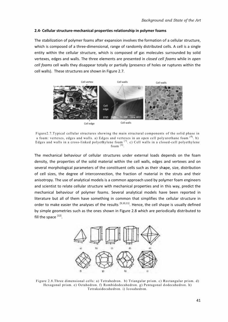
2.4‐
The whic
entit
vert
cell fcell
Figu
a fo
Edg
The dens
seve
of c
anis
and mec
liter
orde
by sfill t
Fig
Cellular stru
stabilization
ch is compos
ty within th
texes, edges foams cell wwalls). Thes
ure2.7.Typic
oam: vertexe
ges and walls
mechanical
sity, the pro
eral morpho
cell sizes, th
otropy. The scientist to
chanical beh
rature but a
er to make esimple geom
he space [12].
ure 2.8.Thre
Hexagonal
ucture‐mech
n of polymer
sed of a thre
he cellular st
and walls. Twalls they dis
se structures
al cellular st
s, edges and
in a cross-li
l behaviour operties of t
logical param
e degree of
use of analy
relate cellul
haviour of p
ll of them h
easier the an
etries such a.
e dimensiona
prism. e) Oc
hanical prope
foams after
ee‐dimension
tructure, wh
The three ele
sappear tota
are shown i
tructures sho
walls. a) Ed
inked polyeth
of cellular the solid ma
meters of thf interconne
ytical models
ar structure
polymer foa
have someth
nalyses of thas the ones s
al cells: a) Te
tahedron. f)
Tetrakaid
erties relatio
r expansion inal, range of
hich is comp
ements are ally or partia
in Figure 2.7
wing the ma
dges and vert
hylene foam
foam [ 8] .
structures u
aterial within
e constituen
ection, the f
s is a commo
with mecha
ms. Several
hing in comm
he results [9,1
shown in Fig
etrahedron.
Rombidodec
decahedron. i
B
onship in po
nvolves the f randomly d
posed of gas
presented inally (presence
.
in structural
exes in an op[ 7] . c) Cell w
.
under extern
n the cell w
nt cells such fraction of m
on approach anical prope
analytical mon that sim10,11]. Hence, gure 2.8 whi
b) Triangula
ahedron. g) P
) Icosahedro
ackground a
lymer foams
formation odistributed cs molecules n closed cell fe of holes or
components
pen cell polyu
alls in a clos
nal loads de
alls, edges a
as their sha
material in t
used by poly
rties and in tmodels hav
mplifies the the cell sha
ch are perio
r prism. c) R
Pentagonal d
n.
and State o
s
of a cellular scells. A cell issurrounded foams while
r ruptures w
of the solid
urethane foa
sed-cell poly
epends on t
and vertexes
ape, size, dis
the struts a
ymer foam ethis way, pr
ve been rep
cellular stru
pe is usually
odically distri
Rectangular p
dodecahedron
of the Art
41
tructure, s a single
by solid e in open
within the
phase in
m [6] . b)
ethylene
he foam s and on tribution
and their engineers edict the
ported in ucture in y defined buted to
prism. d)
n. h)

Chapter
42
Despite conditio
literatur
which thsection b
Figure
In the p
represen
and the
Figure 2
These c
elastic rgrows li
recovera
compres
compres
cell foam
r 2
the great si
ons. Gibson re but at the he cells are abeams, of sid
e 2.9.Cubic c
particular cas
nted in Figur
polypropyle
2.10. a) TPS
urves, regar
region, the pinearly so d
able. Figure
ssion, which ssion. The co
ms. In the c
mplicity of t&Ashby [1], same time o
assumed to de te and cel
ell represent
se of applyi
re 2.10 in wh
ene foams (P
foam stress-
PP
rdless of the
plateau and tdoes the str
2.11 show
are bending
ontribution oase of open
these model
for instance
one of the mbe cubes wh
l walls of thic
ation of Gibs
ng an uniaxihich typical sP) produced
-strain curve
P foams at lo
e polymer e
the densificarain, the de
ws the main
g and axial dof the last twn cell foams
s, they prov
e, developed
most frequen
hose edges, ckness tf (Fig
son and Ashb
material.
xial compress
stress‐strain in this work
up to high s
ow strains (be
employed, sh
ation regioneformation i
deformatio
deformation wo mechanism
the gas flow
ved to work d one of th
tly employed
of length l, agure2.9).
by . a) Open c
sion the beh
curves of thk are plotted
trains. b) Str
elow 20%).
hare three c
n. In the lineanduced in t
on mechanis
of the edges
ms is only sig
ws between
well, but on
e simplest m
d. It is the cu
are formed b
ell material.
haviour is sim
he thermopla
.
ress-strain cu
common reg
ar elastic regthe foam is sms of cells
s, cell wall stgnificant in th
cells and it
nly under spe
models foun
ubic cell mod
by squared‐c
b) Closed c
milar to the
astic starch (
urves of TPS
gions: the ligion as the s almost ent
s under uni
tretching and
he case of cl
ts contributio
ecific nd in del in cross
cell
one (TPS)
and
inear tress tirely iaxial d gas osed on is

scar
sign
Figu
The the foam
sand
of y
gene
app
Onc
with
stre
by a
usua
rigid
prod
will in st
with
desi
by t
rce. Only w
ificant[1].
ure 2.11. Lin
foam stiffne
curve in the
ms for struct
dwich panels
yachts. A mo
eral behavio
lications of t
e the stress
hout opposin
ss, is called pa stress whic
ally attribute
d polymers sduced in this
be discussed
tructural ap
hout failure) gning crash he foam dur
when filling
ear elastic de
ess is quantif
e linear elas
tural elemen
s in structura
ore detailed
our of a san
the non‐cros
s reaches a c
ng any additi
plateau. The
ch quantifie
ed to elastic such as PP, as work (Figu
d in section 2plications (a
and the are
protection aring the load
the foam w
eformation m
fied by the cstic region. Snts. For inst
al applicatio
explanation
dwich panel
slinked PP fo
certain level
onal resistan
e border betw
s the collapbuckling for
and to brittlere 2.12). The
2.5 and in chaccounts for a under the
and protectiv[1].
with fluids o
mechanisms o
compressive Stiffness is a
tance, stiff f
ns in which n about how
l is found in
oams develo
l the cellula
nce. This reg
ween the linpse strength
elastomeric
e crushing su
e reason wh
hapter 4. The
r the maxim
stress‐strain
ve‐packaging
B
of high visc
of a) open cel
modulus, wa very impo
oamed pane
lightness is w the foam
n section2.6.ped in this w
r structure c
gion, in which
near elastic rof the foam
c foams, to thuch as in the
hy starch bas
e collapse str
um stress th
n curve in thg because it
ackground a
cosity can t
ll foams and
which is calcu
rtant param
els are empl
also required
ed core stiff
4 because it
work.
collapses an
h the strain iregion and thm. The collap
he formation
e case of the
sed foams aength is an ihat can be a
e long plate
determines t
and State o
this contribu
b) closed ce
ulated as the
meter used t
loyed as the
d, such as inffness influe
t is one of t
d the foam increases at he plateau ispse mechan
n of plastic he starch‐base
re considere
important pa
applied to t
eau region is the energy a
of the Art
43
ution be
ll foams.
e slope of to design e core of n the hull nces the the main
deforms constant
s marked nisms are inges for
ed foams ed brittle arameter the foam
used for absorbed

Chapter
44
Figu
Finally, tdensity As a re
perform
in Figure
Figure 2
Equation
cell foa
deforma
theory o
r 2
ure 2.12. Cel
the foam de
increases. Th
esult the str
med in an op
e 2.13.
2.13. X‐ray tstrain (w
n 2.1 describ
m subjected
ation mecha
of Timoshenk
ll collapse m
forms to suc
his is why thress grows a
en cell polyu
omography white boxes).
bes the Gibsod to uniaxi
anism of the
ko & Godier [
mechanisms: a
c
ch extent tha
is region is uabruptly. Th
urethane foa
images of a pThese image
on & Ashby mal compress
e edges. This[13].
a) elastic buc
crushing.
at opposing usually referr
he different am can be m
polyurethan
es have been
model within
sion into ac
s equation i
=
ckling, b) pla
cell walls an
red to as denstages of a
measured by
e foam as a n taken in th
n the linear ccount and s obtained b
astic hinges a
nd edges tou
nsification re
a uniaxial c
means of X‐
function of te three regio
elastic regio
supposing by using the
and c) brittle
uch and the fegion (Figure
compression ‐ray tomogr
the compres
ons[6].
n taking an obending as
e standard b
foam e 13).
test aphy
sive
open the
beam
.

Background and State of the Art
45
In equation 2.1 the compressive modulus of the foam (Ef) depends on the compressive modulus of the solid polymer (Es), on the relative density (ρf/ρs) and on the cellular structure. The influence of the cellular structure is mainly included in the exponent n. Experimental results obtained for low‐density open cell polymer foams fit well with the previous equation if n is estimated as 2 [1]. For this reason, it is generally assumed that the compressive modulus of a foam decreases quadratically with the density. Figure 14 shows a plot in which the compressive modulus of a foamed polymer is represented versus density. The blue line represents a linear decrease (n=1) of the compressive modulus while the red line (n=2) represents a quadratic reduction.
Figure 2.14.Compressive modulus versus density of a foamed material in terms of the cubic cell
model.
From this model it is obvious that density is the main factor determining the mechanical properties of polymer foams. However, several strategies can be used to reduce the strong effect of density. One of them is improving the properties of the solid polymer matrix before the foaming process as pointed out by the green arrow in Figure 2.14. In this sense, the reinforcement with fillers, crosslinking and the blending with other polymers are typical approaches. The other one is improving the cellular structure to shift the exponent n from 2 up to values between 1 and 2 as marked by the yellow arrow. The improvement of the cellular structure can be carried out, for instance, by obtaining closed cell foams, reducing the width of the cell size distribution, increasing cell density and modifying the anisotropy ratio.
In the following sections (2.4.1 and 2.4.2) the previous strategies proposed to improve the mechanical properties of a polymer foam are tackled in more detail but being more focused on the production of anisotropic cellular structures and on the reinforcement of the polymer matrix with natural fibres and nanoclays. In principle, the use of natural fibres seems to be an ideal reinforcement strategy for starch‐based materials with the aim of maintaining their bioderived and biodegradable character. Therefore, this strategy could be employed for the development of eco‐friendly food‐packaging trays as stated in Chapter 1. On the other hand, the development of polypropylene foams reinforced with nanoclays and with anisotropic cellular structures is also a
Co
mp
ress
ive
mod
ulus
(Ef)
Density (ρf)
n=2
n=1

Chapter
46
very int
polymer
2.
There ar
their me
Figure 1mechan
size diststruts al
closed ccontribu
except f
Figure
The pro
challeng
compos
structur
mechan
mechan
sections
Fi
r 2
teresting ap
r and hence,
.4.1‐ Improv
re several wa
echanical pe
5,could be oical propert
tribution imp
long the foa
cell foams is
ute to the o
for flexible po
e 2.15.Polica
oduction of ge for scient
ed of elonga
e was previ
ical response
ical behavio
s.
gure 2.16. Po
proach to i
producing r
ving the cellu
ays of impro
rformance. Done of them,
ies measure
plies a homo
m volume re
s undoubted
overall mech
olymers.
rbonate foam
anisotropic tists and ind
ated cells an
iously shown
e anisotropic
our of foam
olymer foam
ncrease the
igid foamed
ular structure
oving the cell
Decreasing cbut previou
ed at low str
ogeneous dis
esulting in bly greater th
anical respo
ms of the sam
21.5 µm
cellular stru
ustry. Aniso
nd they can n in chapterc. Several an
ms with elon
s with differe
b) anisotrop
e properties
materials w
e: the role of
lular structu
cell size in fous works repo
rains [14,15,16].
stribution of
better mecha
han that of onse [1]. The
me density: 0.
m. b) 4.9µm
uctures (Fig
tropic cellul
be found in
r 1 (Figure nalytical mod
ngated cells,
ent structure
pic cellular st
of the foa
hich can be r
f Anisotropy
re of polyme
oams of the sorted a scarc
. On the oth
f the solid panical prope
open cell fo gas contrib
6 g/cm3 and [ 14 ] .
ure 2.16) in
ar structure
n nature, su
1.11). This k
dels have bee
, which are
s: a) isotropi
tructure.
am without recycled afte
y
er foams in osame density
ce influence her hand, naolymer with
rties[2,3]. The
oams becaus
bution is gen
very differen
n a controlle
s are charac
ch as in Bal
kind of struc
en developed
explained
ic cellular str
crosslinking
er end‐use.
order to enh
y, as observe
of cell size inarrowing thehin the walls
e performanc
se the faces
nerally negli
nt cell sizes:
ed way is s
cterized as b
sa wood, w
cture makes
d to describe
in the follo
ructure and
g the
ance ed in n the e cell s and ce of s can gible
a)
till a being hose s the e the wing

Hub
prop
the peri
prism
as sthis wor
The defi
that
the in w
anis
Elon
com
(z)an
beam
plan
2.4.1.1
ber & Gibsonperties of an
same becau
odically dist
matic cell in hown in Figu
reason, this
k.
idealized axned called sht is, by dividi
other two pwhich the c
otropy ratio
ngated cells rmpressive mo
nd assuming
ms, as show
nes to the ex
1‐ Rectangula
n [17] modifie
nisotropic po
se the cell istributed to f
which the st
ure 17. The axis will be
Figure 2
xysimmetric chape anisotrng the lengt
perpendicula
ell dimensio
should be d
result in diffe
odulus of the
g bending as wn in equati
pansion dire
ar cell model
ed the cubic
olymer foam
s held by squ
fill the space
truts in the zz direction ufrequently
2.17. Rectang
cell represen
ropy ratio or
h of the stru
r directions
ons vary in efined at lea
erent mecha
e cell repres
the deforma
on 2.3. Hen
ection becaus
l
c cell model
s in terms ouared cross‐se. Neverthe
z direction ausually coinc
denominate
gular cell us
nted in Figur
anisotropy ruts (h) in the
(l). Neverthe
the three d
ast in two pla
=anical proper
sented in Fig
ation mode,
nce, the foam
se their edge
=
B
with the ai
of an idealize
section beam
less, the cu
re larger tha
cides with thed as the exp
ed by Huber
e 17 allows aratio (R) wh
expansion deless, it is po
directions(z≠anes.
rties depend
gure 2.17, lois inversely pm is weaker
es are larger
ackground a
m of descri
ed elongated
ms of the sam
bic cell turn
an those in the foam expa
pansion direc
and Gibson.
a morpholog
ich is calcula
direction and
ossible to fin≠x≠y) and th
ing on the lo
oaded in the
proportional
r when load
.
and State o
bing the me
d cell. The co
me dimensio
ns into a rec
he x and y dansion direc
ction throug
gical parame
ated by equa
d the length nd orthotropherefore, th
oading direct
e expansion l to the leng
ded over the
of the Art
47
echanical oncept is ns and is
ctangular directions ction. For ghout the
eter to be ation 2.2, in any of pic foams he shape
.
tion. The direction th of the
e parallel
.
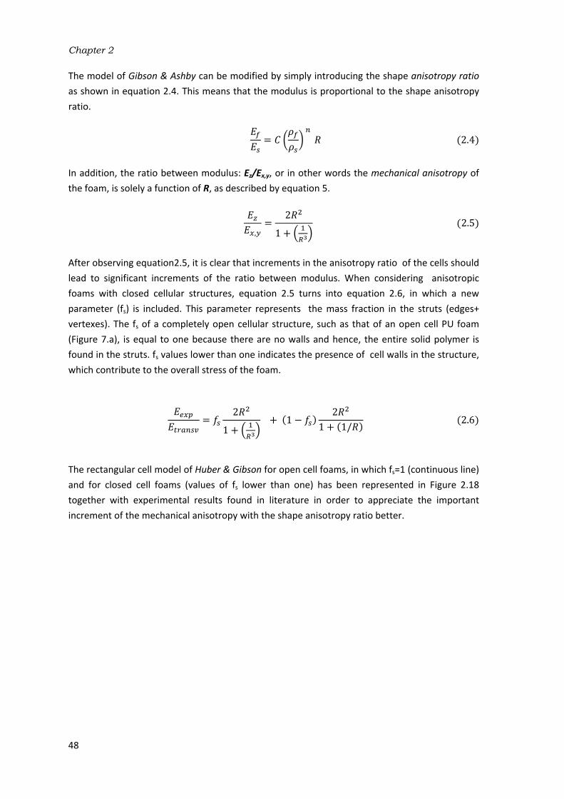
Chapter 2
48
The model of Gibson & Ashby can be modified by simply introducing the shape anisotropy ratio as shown in equation 2.4. This means that the modulus is proportional to the shape anisotropy ratio.
= .
In addition, the ratio between modulus: Ez/Ex,y, or in other words the mechanical anisotropy of the foam, is solely a function of R, as described by equation 5.
, = + .
After observing equation2.5, it is clear that increments in the anisotropy ratio of the cells should lead to significant increments of the ratio between modulus. When considering anisotropic foams with closed cellular structures, equation 2.5 turns into equation 2.6, in which a new parameter (fs) is included. This parameter represents the mass fraction in the struts (edges+ vertexes). The fs of a completely open cellular structure, such as that of an open cell PU foam (Figure 7.a), is equal to one because there are no walls and hence, the entire solid polymer is found in the struts. fs values lower than one indicates the presence of cell walls in the structure, which contribute to the overall stress of the foam.
= + + − + / .6
The rectangular cell model of Huber & Gibson for open cell foams, in which fs=1 (continuous line) and for closed cell foams (values of fs lower than one) has been represented in Figure 2.18 together with experimental results found in literature in order to appreciate the important increment of the mechanical anisotropy with the shape anisotropy ratio better.

Fig
A teis mMor
1887
Mor
tetra
cont
show
wall
The and
gure 2.18.Co
experim
2.4.1.2
etrakaidecah
more similar treover, it als
7 to define w
re recently, akaidecahed
tains eight hwn in Figure
s).
Figure
size and sha
D. In this wa
mpressive m
ental values
polyisocy
2‐ Tetrakaide
edron is a ce
to the real sh
so packs to fwhat is called
Sullivan etdron cell to chexagonal fae 19. The m
2.19. Elonga
ape of this ce
ay, two morp
1,0
1
2
3
4
5
EZ/E
X,Y
odulus ratio
for low-dens
anurate [ 19] , (
ecahedron ce
ell geometry
hape of cells
fill the space
d today the K
t al. develo
calculate the
ces, two hor
odel was on
ated tetrakaid
ell can be def
phological pa
1,2
versus the sh
sity polymer
(▼) PU(F), H
ell model
y which has bs in low dens
e. This geom
Kelvin cell mo
oped a gen
e foam stiffn
rizontal squa
nly develope
decahedron c
fined by spe
arameters ar
1,4 1
R
B
hape anisotro
foams:(◄) P
Hilyard [ 20] an
been extensi
sity foams th
etry was ori
odel [21].
neral model
ess [22,23]. Th
are faces an
ed for open c
cell represent
cifying three
rise: one is R
,6 1,8
Eexp.
PS
PU F H
PU F As
PUR
Polyisoc
fs=1 ope
fs=0.8
fs=0.6
fs=0.4
fs=0.2
ackground a
opy ratio. Th
PU(R), (♦) PU
nd (▲) PS [ 1 8
vely used in han the prev
ginally empl
also based
is elongated
d four vertic
cell foams (i
ted by Sulliva
e of the cell dR or anisotrop
2,0
ilyard
shby
cyanurate
en cell
and State o
heoretical mo
U(F) [ 18] , (►)8] .
literature bious rectang
loyed by Tho
d on an e
d tetrakaidec
cal diamond
i.e foam wit
an et al [ 2 2 ] .
dimensions: opy ratio (eq
of the Art
49
del and
)
ecause it gular cell. omson in
longated cahedron faces as hout cell
b, L, , H uation 7)

Chapter
50
and the 2.20 in ware show
Other a
describe
be exclu
apparen
simple ganisotro
density o
This mo
much hi
last sect
PP based
r 2
other is Q which two ewn.
Figure 2.20
uthors, such
e the mechan
usively funct
nt reason to
geometrical opy of foams
of the foam
, =odel also pre
igher than t
tions will be d foams dev
(equation 2.
longated tet
0.Tetrakaidec
h as Gong etnical behavio
tion of be
make such
reasons. Equ
s and it is wr
(ρf/ρs).
= edicts that th
he modulus employed in
eloped in th
.8). Both of trakaidecahe
= =
cahedron cel
t al [24], also our of open c
ecause they a restrictio
uation 2.9 written in term
+ 6 +he modulus
in the perp
n chapter 5is thesis.
them can vedron cells w
+= cos
ls with the sa
employed a
cell foams bassumed th
on as these was develope
ms of the cel
+
in the direc
pendicular di
in order to a
ary indepen
with the same
√
ame R but di
an elongated
ut they restr
hat b/L=cos parameters
ed by Sullivanl dimensions
ction in whic
irection. The
analyse the
dently as sp
e R and diffe
fferent value
d tetrakaide
ricted the sha
. Neverthe
can vary in
n to describe
s (b, L and)
ch the cells e models pre
mechanical
pecified in Fi
erent values
es of Q.
ecahedron ce
ape of the ce
less, there i
ndependently
e the mecha
) and the rel
are elongat
esented in t
behaviour o
igure of Q
.
.
ell to ell to is no y for
anical ative
.
ed is these f the

The mec
wall
deve
in thnano
the supp
of thact t
The in te
effe
adds
hete
form
nucl
by othe ther
varia
as th
The show
or fi
2.4.2‐ Rei
reinforceme
chanical perf
s and edges
eloped in thi
he case of thoclays. In an
medium to tports the str
he matrix. Bo
together to i
mechanical erms of how
ct of the fills a great de
erogeneous mation is fav
leating sites orange symb
generation refore, lowe
ations of the
he expansion
fillers usual
wn in the sc
ibres. In term
inforcement
ent of the po
formance of s becomes a
is research bhe PP‐based n ideal situat
transmit the
ructure beca
oth compon
improve the
properties ow the solid p
ers during tal of comple
nucleation m
voured in th
could be inc
ols and the of more h
er cell sizes
e polymer mn stage and s
Figure 2
ly employed
heme of Fig
ms of their c
with fillers:
olymer matri
foams as de
a composite
because they
foams invest
tion the poly
external for
ause their sti
ents not only
foam mecha
of polymer cphases invol
he foaming exity in these
mechanisms
e liquid‐solid
creased as scell nuclei by
homogeneou
. Moreover,
matrix viscosi
stabilization
.21.Heteroge
d to reinforce
ure 2.22. Wi
chemical com
polymer com
ix with fillers
enoted in Fig
e. A biocom
y are reinfor
tigated in th
ymer matrix rces to them
iffness and sy preserve tanical perfor
composite‐blved, polyme
process has
e systems. Fs during the d interface. shown in Fig
y black circle
us cellular , a good a
ty, which in process.
eneous nucle
e polymers ith regards tmposition th
B
mposites
s represents ure 14. In th
posite in th
ced with nathis research b
acts not onl
m, while filler
strength are heir chemica
rmance [2].
based foams
er and filler
s also to be For instance,
first stages
As a conseq
ure 2.21 in wes. Theoretic
structures dhesion bet
turn could a
ation of cells
are classified
to shape, the
hey can be m
ackground a
another stra
is way, the se case of th
tural fibres abecause they
y as the filles are the com
considerabl
al and physic
cannot be es, interact w
taken into a, it is known
of foaming
quence, the which the filcally, this fac
with higher
tween the s
affect other
s with fillers
d according ey can be co
mineral or or
and State o
ategy to imp
solid phase inhe TPS‐base
and a nanocoy are reinfor
ers binder bu
mponent wh
y greater thcal identities
exclusively ewith each ot
account and n that fillers g because th
number of llers are rep
ct should bri
r cell densi
solid phase
foaming sta
.
to several considered as rganic fillers.
of the Art
51
prove the n the cell ed foams omposite rced with ut also as hich truly an those
s but also
evaluated ther. The
this fact promote
he nuclei potential resented ng about ties and s causes
ages such
riteria as particles
. Mineral

Chapter
52
fillers su
many de
fillers, o
with the
drawbac
fillers ca
This last
Organic compos
as hemi
which hof the 2
replaced
mechan
natural anhydro
C4positio
r 2
uch as calciu
ecades with or synthetic fe aim of imp
ck associate
an be also cla
t classificatio
Figure 2.2
2.4.2.1‐ Na
fillers such
ed of cellulo
celluloses, pave been us
20th century,
d by synthetical perform
linear poly
oglucose (C6
on [25] (Figure
m carbonate
the main pu
fillers such a
roving the pd with mine
assified in re
on will be dea
22. Fillers cla
atural fibres
h as naturalose fibrils em
pectin and wsed in the pr
, they were tic fillers due
mance. Their ymer with
6H11O5) repe
e 2.23).
e, talc, silica,
urpose of de
as glass fibre
performance
eral fillers is
elation to the
alt with in m
assification a
l fibres are mbedded in awaxes. This isreparation of
principally u
e to the lack
reinforcing ea degree o
eating units
, clay, etc. hcreasing cos
es, glass sph
of the polym
s their relati
eir size: from
ore detail in
according to
naturally o
a lignin matr
s the case of
f composites
used in airc
k of data ab
effect lies in of polymeri
joined by
ave been us
st. On the ot
heres and ca
mer for struc
vely high de
m micrometri
section 2.4.
their chemist
occurring co
ix, among ot
f the natural
s since histo
raft applicat
bout their p
the cristallin
ization abou
1,4‐‐D‐gly
sed in the pla
her hand, fuarbon fibres ctural applic
ensity [2]. Las
c fillers to na
2.3.
try, shape an
mposites be
ther minor cl fibres obta
orical times. Ations but we
roperties an
nity of cellulo
ut 10000 c
ycosidic linka
astic industr
unctional min
were develo
cations. The st but not l
anometric fi
nd size.
ecause they
components ined from pAt the begin
ere progress
nd to their lo
ose. Cellulose
consisting o
ages at C1
ry for neral oped main east, llers.
y are such lants
nning sively ower e is a
of D‐and
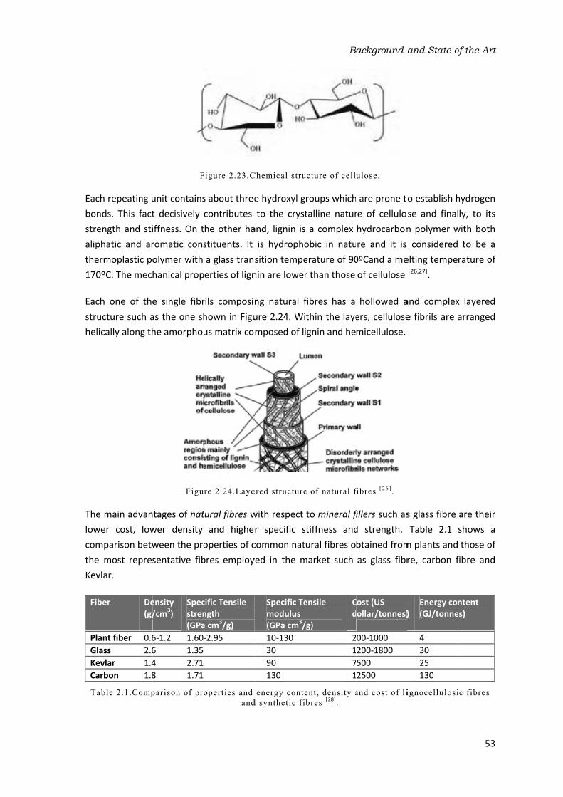
Each
bon
stre
aliph
ther
170º
Each
stru
helic
The lowe
com
the Kevl
Fib
Pla
Gla
Kev
Car
Tab
h repeating uds. This fact
ngth and sti
hatic and ar
rmoplastic po
ºC. The mec
h one of the
cture such acally along th
main advan
er cost, low
mparison betw
most repres
lar.
ber De(g/
ant fiber 0.6
ass 2.6
vlar 1.4
rbon 1.8
ble 2.1.Comp
F
unit contains
t decisively iffness. On tromatic cons
olymer with hanical prop
e single fibr
as the one sh
he amorpho
Figu
tages of natwer density ween the pro
sentative fib
ensity /cm
3)
Specstren(GPa
6‐1.2 1.60
6 1.35 4 2.71 8 1.71
parison of pr
Figure 2.23.C
s about three
contributes
the other ha
stituents. It a glass tran
perties of lign
rils composin
hown in Figu
us matrix co
re 2.24.Laye
tural fibres wand highe
operties of cbres employ
cific Tensile ngth a cm
3/g)
‐2.95
operties and
and
Chemical stru
e hydroxyl gto the cryst
and, lignin isis hydropho
sition tempe
nin are lower
ng natural f
ure 2.24. Wi
mposed of li
ered structure
with respect r specific s
common nat
yed in the m
Specific Temodulus (GPa cm
3/
10‐130
30
90
130
energy conte
d synthetic fi
B
ucture of cell
roups which
talline natur
a complex
obic in natu
erature of 90
r than those
fibres has a thin the laye
ignin and he
e of natural f
to mineral ftiffness and
ural fibres omarket such
ensile
/g)
Cd
2
1
7
1
ent, density a
bres [ 28]
.
ackground a
ulose.
are prone tore of cellulo
hydrocarbon
re and it is 0ºCand a me
of cellulose
hollowed a
ers, cellulose
micellulose.
fibres [ 2 6 ] .
fillers such as
d strength. btained from
as glass fibr
Cost (US ollar/tonnes)
00‐1000
200‐1800
500
2500
and cost of li
and State o
o establish hse and final
n polymer w considered
elting tempe[26,27].
and complex
e fibrils are a
s glass fibre Table 2.1
m plants and
re, carbon f
) Energy co(GJ/tonne
4 30 25 130
ignocellulosi
of the Art
53
hydrogen lly, to its
with both to be a rature of
x layered arranged
are their shows a those of
fibre and
ntent es)
ic fibres

Chapter
54
Moreov
produce
employe
They are
least, thresource
industry
would b
On the nature wvery diff
the pres
tempera
higher t
suscepti
fillers be
such as g
The inhe
starch‐bglucose.
Amylose
presents
also fou
synthesi
semicrys
seeds, r
germina
Figur
r 2
er, handling
ed when usi
ed in their pr
e good therm
e environme
e available wy is favoured
e a residue.
other hand,
which makes
ficult. This fasence of vo
ature of the temperature
ible to rootin
ecause of thglass fibres f
2.4.2.2‐Sta
erent polarit
based mater
. In fact, star
e is a primar
s multiple br
und in starch
ized in the stalline gran
roots, tuber
ation or when
re 2.25.Starch
natural fibr
ng mineral rocessing, thmal and acou
ental impact
worldwide an
d because th
, they also p
s their mixin
act also con
oids in the i
resultant co
es. Their mic
ng. Moreove
eir natural ofor natural fi
arch‐based b
ty of naturalrials because
rch is a polys
rily linear po
ranches join
h such as lip
amyloplast
ules (Figure rs, stems a
never energy
h granules in
res is safer bfibres, are
hus the costs
ustic insulato
associated wnd their prod
he value of
present som
ng with non‐tributes to hnterface bet
mposites is crobial resist
er, their prop
origin. These
ibres for the
iocomposites
l fibres make
e both, star
accharide co
lymer with (ed to the m
pids, proteins
t of plant c
2.25) with and leaves r
y is needed f
n the amylopl
because der
reduced. Th
s associated ors because with their us
duction requ
this natura
me drawback
‐polar therm
high moistur
tween the f
restricted totance is very
perties are ne drawbacks
reinforceme
es
es them idea
rch and cel
omposed of t(1→4) linked
main chain by
s, fatty acid
cells where a density of arepresenting
for the plant
last. Amylos
mal and res
hey are non‐with machin
of their holl
se is lower bires little en
l product is
ks. Natural fmoplastics ob
re absorptio
fibres and t
o 200ºC as fiy low makin
not as homo
make the re
ent of synthe
al fillers whe
lulose, share
two polymer
d ‐glucosyl y (1→6) linka
s and phosp
it is dense
around 1.5 gg their mai
t.
e and amylop
piratory irrit
‐abrasive fo
ne maintenan
owed struct
ecause they ergy. In this increased, w
fibres have a
btained from
n leading tohe polymer.
bres underg
ng the comp
genous as theplacement etic polymers
en used as re
e the same
rs: amylose aunits where
ages. Minor phate ester g
ely packed g/cm3. Starch
n source of
pectine chem
tations, norm
r the machi
nce are redu
ture. Last but
are a renew
way, agricul
which other
a polar chem
m fossil‐resou
o swelling an
. The proce
go degradatio
posites prod
hose of syntof mineral fs challenging
einforcemen
e repeating and amylope
eas amylope
component
groups. Star
in the form
h can be foun
f energy du
mical structur
mally inery uced. t not
wable tural
rwise
mical urces nd to ssing on at uced thetic fibres g.
nt for unit: ectin. ctine s are
rch is m of nd in uring
e.

Star
Dep
poly
m in Fi
a bi
gran
Star
mod
the dens
app
stru
ope
rch is extract
pending on ygonal, disk ain diameter[
igure 2.26. Pmodal distr
nules have a
Figure 2.
rch is a sem
del that desc
granule con
sity semicry
roximately 1
ctures called
nings of inte
Figu
ted from th
the botanic
and elongate[29]. The gran
Potato starch
ibution of s
spherical sh
.26. Starch g
micrystalline cribes the inn
nsists of 120
ystalline and
10 nm thick d blockets.T
erior channel
ure 2.27.Org
e plants by cal origin, st
ed to name bnule morpho
h granules ca
izes in whic
ape.
ranules used
polymer wit
ner structure
0 to 400 nm high‐densit
lamellae wh
he pores pr
s located wit
anization mo
gravity sedi
tarch granu
but a few, an
ology of the tan be either och the large
in this resea
th crystalline
e of starch gr
thick conce
ty crystalline
hich are beli
resent on th
thin the star
odel of the st
B
imentation, les have di
nd different stwo starches
oval or sphe
granules ha
arch: a) Whea
e contents v
ranules is sh
entric shells,
e shells. The
ieved to be he surface o
rch granule [3
tarch granule
ackground a
centrifugatio
fferent shap
sizes: from les employed irical while wave a disk s
at starch. b) P
varying from
own in Figur
which alter
ese shells in
organized in
of the granu30].
structure.[31
and State o
on and filtra
pes: spheric
ess than 1 in this work
wheat starch shape and t
Potato starch
m 15 to 45%
re 2.27. In thrnates betwe
n turn, are nto pseudo‐ules are the
1][32,33,34]
of the Art
55
ation [29]. cal, oval, m to 100 is shown presents he small
h.
% [29].The his model een low‐made of spherical external

Chapter
56
The pro
injection
Some wis 227 °
starch inas to d
biodegra
be adde
amounts
plasticiz
lower gl
certain a
The plas
The pro
uptake bamylose[37].This p
Figur
Plasticiz
extruder
twin‐scr
that of o
r 2
ocessing of s
n machines works reporte
C, whereas n the form oecrease the
adability [32‐3
ed. The plast
s. Moreove
ed into thermlass transitio
applications
sticization pr
ocess is split
by the amor
e leaching. F
process is sh
re 2.28. Ligh
ation can be
rs or internarew extruder
other synthe
starch granu
and presses
ed that the gothers dete
of granules we final cost 34]. However
ticization of r, the proce
moplastic ston temperat
such as plas
rocess is call
t up into sev
rphous regio
Finally, starc
hown by light
ht micrograph
e carried out
al mixers. F
r and a SEM
tic thermopl
les by comm
s is very diff
glass transitirmined that
was originally
of the com
, only a limit
starch allow
essing of st
arch (TPS) wture. Nowad
tic bags [36].
led gelatinizaveral stages
ons, loss of cch granules t microscopy
hs of wheat s
t not only un
Figure 2.29 s
M image sho
lastics.
mon plastic ficult becaus
ion temperat
t the Tg of d
y employed mposite and
ted amount
wed it to be tarch itself
which is a ma
days, TPS is
ation when s: diffusion o
crystalline or
completely y in the imag
tarch gelatin
nder heat bshows pellet
owing the co
industrial eq
se they only
ture (Tg) of ddry starch is
as natural fiat the sam
of starch, ablended wit
improved b
aterial mostly
commerciall
starch is dilu
of water int
rder, radial sdisintegrate
ges of Figure
nization unde
ut also unde
ts obtained ontinuous m
quipment su
melt after dry amylose
332 °C [31]. iller in synth
me providing
round 30 % th other poly
ecause gran
y amorphous
ly available
uted with wa
o the starch
swelling of the and form
2.28.
r microwave
er shear forc
after plastic
orphology o
uch as extru
being degra
and amylop
For this rea
hetic polyme
g it with ce
in weight, cymers in gre
nules turn w
s material w[35] and used
ater and hea
h granule, w
he granules,
a viscous b
radiation [ 3 7
ces in twin scizing starch of TPS, simila
ders, aded. ectin ason, rs so rtain
could eater while
with a d for
ated. water , and atter
7] .
crew in a
ar to

Fi
Effic
with
hydr
sorb
Wat
strin
obta
Wat
blow
be proc
glyc
agin
amb
resu
The whic
of m
alth
cont
amo
Star
visco
Nev
The prop
Ther
mos
Tabl
natu
gure 2.29. a)
cient plastici
h low viscos
rogen bonds
bitol, urea an
ter, because ngent becau
ained are le
ter is usually
wing agent. Oproduced. I
cessing tem
erol are mo
ng or retrog
bient tempe
ultant TPS is
plasticizatio
ch is the red
mechanical p
ough the de
tent of glyce
ounts result i
rch plasticize
osity to be pertheless, itsreinforceme
perties and are are severa
st of them thle 2.2 shows
ural fibre em
)Thermoplast
izers are gen
sities. The m
s between t
nd formamid
it is widely ase of its low
ss durable, y employed On the othe
Its volatiliza
peratures in
ore durable. gradation, w
rature in t
brittle itself
on process oduction of mproperty red
egree of pla
erol was fou
in brittle TPS
ed with high processed in s stiffness an
ent with nat
at the same al works in lihe plasticize
a list of the mployed, th
tic starch pel
d
nerally mole
mechanism the plasticize
de but wate
available and
w volatilizat
prone to ro
when TPS isr hand, glyce
ation tempe
ncrease subs
However, T
hich is a re
time. Urea i
and mixture
of starch invo
echanical pr
duction depe
asticization und to be in S and higher
contents of
plastic equip
nd strength ural fibres re
time to ma
terature dea
r contents amain works
e productio
llets. b)SEM
during this th
ecules or po
of plasticiza
er and starc
er and glyce
d cheap. Nev
tion tempera
ooting and m
s subsequent
erol is a bett
erature is h
stantially. M
TPS plasticize
ecrystallizatio
is a plasticiz
es with other
olves a dras
roperties due
ends on the
is the facto
the range o
amounts lea
f glycerol (ab
pment and iare low in c
epresents a gintain the b
aling with the
are about 30
on the topic
on route fol
B
micrograph
hesis.
lymers with ation is mai
h. Common
rol are the m
vertheless, thature (100ºC
more sensitiv
tly foamed bter alternati
higher (290
Moreover, th
ed with glyc
on phenome
zer that act
r plasticizers
tic change oe to the loss
e kind and a
or with the of 20‐35 wt%
ad to glycero
bout 35 wt%
t is soft and omparison wgood approa
ioderivability
e reinforcem
0wt%andglyc
c specifying tlowed and t
ackground a
of a plasticiz
low molar nly based o
plasticizers most freque
he processing
C) and beca
ve to enviro
because it co
ve when sol
0ºC) and he
he TPS mate
erol during enon that m
ing alone a
are required
of its physica
s of crystallin
amount of p
greater infl
% (percentag
ol exudation.
%) is a materi
ductile at am
with most of
ach to increa
y and biodeg
ment of TPS wcerol is the pthe kind of sthe conditio
and State o
zed starch pr
mass and th
on the form
are water, ently employ
g conditions
ause the com
onmental co
ould also ac
id composit
ence, the r
erials obtain
storing suff
makes TPS b
avoids aging d [38‐39].
al properties
ne order. Th
plasticizer e
uence. An o
ge in weight
ial with an ambient temp
f synthetic pase these me
gradability owith natural plasticizer em
starch, plasti
oning of the
of the Art
57
oduced
herefore, mation of
glycerol, yed [38,39]. s are very mposites
onditions. ts as the es are to range of ned with fers from brittle at
but the
s. One of e degree mployed optimum t). Lower
adequate perature. polymers. echanical of starch. fibres. In
mployed. cizer and e sample

Chapter 2
58
carried out prior to the mechanical tests which is very important due to the water sensitivity of starch.
Author Starch Plasticizer Natural fiber Production method Conditioning Averous
[40] Wheat Glycerol and water
Leafwooda
Single screw extruder+ injection
23ºC. 54%HR. 42 days
Curvelo[41] Corn Glycerol Eucalyptus
urograndis Internal mixer+
thermoforming 22‐25ºC. 43%HR. 14 days.
López[42] Corn Glycerol Recovered
newspaper Internal mixer+
thermoforming Drying to 70ºC for 120 hours/ 53%HR. 20 days.
Martins[43] Corn Glycerol Bacterial cellulose
aInternal mixer+
injection 25ºC. 50%HR.
Eucalyptus globulus
a
Belhassen[44] Starch‐based biopolymer
blended with biodegradable polyester
Esparto Alfa fibresa
Internal mixer+
injection 23ºC. 50%HR. 3 days
Gironés[45] Corn Glycerol Sisal Internal mixer+
thermoforming Drying to 70ºC for 120 hours/ 53%HR. 20 days.
Hemp
Wattanakornsiri[46] Tapioca Glycerol Office paper
aInternal mixer+
thermoforming 23‐25ºC. 44‐55%HR. 14 days. Newspaper
a
Teixeira[47] Corn Glycerol Cotton nanofibres Twin screw extruder+
thermoforming Drying to 70ºC until constant weight/ 23ºC. 53%HR. 30 days.
Müller 1[48] Cassava Glycerol Eucalyptus Casting 25ºC. 58%HR.
Müller 2[49] Cassava Glycerol Softwood short fibres
Casting 25ºC. 58%HR. 2 days
Ma[50] Corn Formamide+Urea Micro winceyette
fibre Single screw extruder+ injection
1 week in plastic bags
aChemically treated to isolate the cellulose fraction.
Table 2.2. Biocomposites based on TPS reinforced with natural fibres reported in li terature.
Several natural fibres of different botanical origins were used in these works such as sisal, hemp and eucalyptus. The final properties of these biocomposites were determined by the chemical composition of the fibres and compatibility with the polymer matrix, the fibres volume fraction, their shape and aspect ratio, their size and finally to the degree of distribution throughout the matrix. The morphology of some of the fibres employed in these works is shown in Figure 2.30, which also includes a SEM micrograph showing how natural fibres are distributed along a thermoplastic starch matrix (Figure 2.30d).

Fi
fib
Figu
in T
mod
natu
Thes
in th
barl
emp
igure 2.30. O
bres [ 40 ] . b) p
newspaper f
ure 2.31 show
Table 2.2re
dulus(Ec/E),re
ural fibre loa
se plots will his work (ch
ley, grape a
ployed in lite
Optic microgr
paper pulp fib
fibres [ 46 ] ,f) c
ws plots rep
lative to th
elative tensilding.
be very usef
hapter 4) w
and cardoonerature (Tabl
raphs and SEM
bres [ 40 ] , c) b
cassava starc
resenting mhose of the
le strength (
ful to evaluat
hich would n, are very e 2.2).
M micrograp
bacterial cellu
h fi lm reinfo
mechanical pr
e correspon
(σc/σ) and re
te the reinfo
be key taki
different to
B
phs of differe
ulose fibres [
orced with eu
roperties of nding TPS w
elative elong
orcement eff
ng into acco
o those of
ackground a
ent fibres: a) [ 43 ] ,d) office
ucalyptus cell
the TPS‐bas
without fibr
ation at bre
ficiency of th
ount that th
the natural
and State o
leafwood ce
paper fibres
lulose fibres
ed composit
res: relativeeak (Ɛbc/Ɛ) ve
he natural fibheir botanica
l fibres trad
of the Art
59
llulose
[ 46 ] , e)
[ 4 8 ] .
tes listed e tensile ersus the
bres used al origin: ditionally

Chapter
60
Figure 2
R
r 2
2.31.Variatio
Relative tensi
n of properti
le modulus. b
ies with the a
b) Relative t
addition of n
ensile streng
atural fibres
gth. c) Relati
for the syste
ve elongation
ems of table
n at break.
2. a)

Background and State of the Art
61
In all these works tensile modulus and strength increases with the addition of natural fibres while the elongation at break decreases. The principal reason found for such improvement is the chemical compatibility between both materials, as the tensile load is effectively transferred from the matrix to the fibres due to H‐bonding between the hydroxyl groups of starch and cellulose [42].On the contrary, the strengthening of the TPS matrix implies a reduction of elasticity and ductility. This effect is expected considering that fibres imparts rigidity and restrains the deformation of the matrix [45].
The chemical composition of these fibres differs because some of them were chemically treated to isolate the cellulose fraction and increase their reinforcing effect. The reason given is that cellulose is composed of glucose as the polymer chain repeating unit, which is polar and therefore, with a high chemical affinity with starch whose polymer backbone is composed of glucose as well. On the contrary, lignocellulose fibres have lignin on their surface, which is a less polar component [40]. Figures 2.30a and b show two kinds of fibres with apparently similar morphology but with different chemical composition. The cellulose based fibre (Figure 30.a) displayed better mechanical properties than the lignocellulose based fibre (Figure 30.b) However, other works stated the opposite claiming that lignin could act as an interfacial compatibilizer between fibres and starch. Lignin, due to its constituent hydroxyl groups and to its location on the surface of the fibres, is able to establish on the one hand, covalent bonds with cellulose and on the other hand, with glycerol and starch [48].
Fibre morphology is usually specified by its aspect ratio which is the ratio between its length and its diameter. It is generally assumed that fibres with high aspect ratios produce larger reinforcements in the polymer matrix than short fibres with low aspect ratios[51]but at the same time, they are more susceptible to damage during the composite production in the sense that fibres are shortened[44]. The level of damage increases with the amount of fibres added due to the increased probability of fibre‐fibre and fibre‐machine interaction and to the higher melt viscosity of the composite, resulting in higher bending forces during compounding and moulding.
Size is another important morphological parameter. For instance, the mechanical performance of Bacterial cellulose fibres, composed of a tri‐dimensional network of nano and microfibrils (Figure2.30c) is higher than that of conventional vegetable fibres at the same loading level [43]. Nanocellulose is produced by acid hydrolysis of cellulose under controlled temperature conditions. After this process, a suspension of needle‐like particles with lengths and diameters of the order of nanometres are obtained. Cotton cellulose nanofibres and Cassava bagasse cellulose nanofibrils were employed to reinforce TPS with very interesting results because the usual increase in tensile modulus and strength obtained with the addition of natural fibres did not involve in this case a loss of elasticity. On the contrary, elongation at break increased with the addition of cellulose nanofibres [47,52].
The influence of the fibres surface was also considered. Figure 2.30e shows cellulosic fibres obtained from newspaper with a hair follicle and rough surface. These fibres, after being mixed with TPS, resulted in higher tensile strengths and modulus than composites produced with

Chapter 2
62
cellulose fibres obtained from office paper whose surface is smother (Figure2.30d). The first surface could provide stronger intrinsic adhesion between the fibres and the matrix [46].
Not only the mechanical properties of TPS are affected by the addition of fibres but also its characteristic thermal transitions such as the glass transition temperature (Tg). Taking the high chemical affinity of both materials into account a restriction of the polymer chains mobility in the vicinity of the fibre phase is expected, resulting in an increase of the overall Tg. This increment can also be due to the interaction between the fibres and the plasticizer that makes the polymer matrix less plasticized than the pure sample. This fact has been reported in literature by means of differential scanning calorimetric measurements (DSC) and by dynamic mechanical thermal analyses (DMTA) [40‐46].[41,44,46,49,53,54]
TPS is very sensitive to the environmental humidity because of its hydrophilic character. This fact is an advantage when the degradation of the polymer after end‐use is studied. Composting conditions usually involve wet environments and therefore, the degradation process of TPS is accelerated. On the other hand, it is a drawback during the service period of the polymer because mechanical properties and dimensional stability are clearly influenced by the absorption of water due to the plasticizing effect of water. The incorporation of natural fibres could reduce the water sensitivity of TPS because of fibre‐matrix interactions and due to the hydrophobic character of cellulose. However, there is not a full agreement in this respect. In some cases the results reveal a clear reduction of the water absorption with the addition of fibres [41‐46,49,53,54].In others, the results are not so conclusive [42,45]. In any case, the absorption of water seems to be more dependent on the relative humidity of the atmosphere to which TPS is exposed than on the incorporation of natural fibres.
One of the reasons for selecting three kinds of natural fibres in this work (barley, grape and cardoon) is that they present very different morphology in terms of shape, size and aspect ratio. These morphological parameters have been found to be very important when determining the final properties of starch‐based composites as this brief description of the literature has proved.
2.4.2.3‐ Polymer nanonocomposites: nanoclays
Explaining the chemistry and structure of nanoclays and how they interact with the polymer in which they are embedded is one of the objectives of this section. During the last 25 years the development and synthesis of nanoparticles has brought about a new class of materials with multifunctional properties called polymeric nanocomposites. Their origin dates back to the early 1990s when the Toyota Central Research Laboratories in Japan produced a nanocomposite based on Nylon‐6 in which small amounts of nanofillers enhanced substantially the thermal and mechanical properties of the original polymer [55].They are called nanoparticles because at least one of their dimensions is in the range of nanometers and can be classified according to their shape (Figure 2.32). They can be considered as laminates, with a platelet‐like structure, in which only one of their dimensions is in the range of nanometres (nanoclays and graphene), tubulars in which two of their dimensions are in the range of nanometres while the third is larger, even in the micron scale, resulting in elongated structures (carbon nanotubes and nanofibres) and finally

sphe
gold
An whic
resu
prop
and VGC
The coun
mec
anot
micr
effe
nano
with
abra
nano
degr
surfa
A go
have
case
to d
erical in whi
d and other m
F
interesting e
ch are hollo
ulting in hig
perties havin
3.5 GPa and
CNF and a SE
Figure 2.3
reason why
nterparts re
chanical prop
ther point of
roparticles toctive. The w
oclays and th nanosilica asion resista
oparticles [58
ree of adh
face/volume
ood dispersi
e been usua
e of solution‐disperse nan
ich all the di
metal nanopa
Figure 2.32.N
example of ow cylinders
gh aspect ra
ng Young´s md very high eM image of a
3.a) TEM im
y the range oesides in th
perties, the lf view, it is po produce thworks of Kohat of Zohu particles ar
ance and ten8,59]. The imp
hesion and ratio tend to
on is depen
lly adopted: ‐blending a snoparticles.
imensions ar
articles and
Nanoparticles
tubular nan
s with diam
atios (length
modulus in th
lectrical con
a VGCNF/ep
mage of VGCN
of properties
e higher suoad transfer
possible to lohe same effe
ojima et al et al in whi
e clear exam
nsile proper
provement o
dispersion
o agglomerat
dent on the
solution‐blesolvent mixtu
It is a very
re in the na
titanium oxi
s classificatio
noparticle is
meters of aro
h/diameter
he range 100
nductivities (oxi nanocom
NF. b) SEM
s is substant
urface/volum
r surface from
oad the poly
ect because tbased on th
ch polyester
mples of ho
rties are enh
of mechanic[60].Nanopa
te more easi
e nanocompo
ending, melt
ure is used ty attractive
B
nometric sca
de) [56].
on as a funct
vapour groound 100 n
100). They 0‐1000 GPa a103 S/cm). Fi
mposite [57].
image of VG
ially wider wme ratio of
m the polym
mer with low
the reinforce
he reinforce
r‐based poly
w mechanic
hanced by t
cal propertie
articles, pre
ily than micr
osite produc
t‐blending ato dissolve th
method w
ackground a
ale (silica pa
ion of their s
own carbon m and leng
possess ve
and tensile sgure 2.33 sh
CNF/epoxy n
with respect nanoparticle
mer to the fillwers amount
ement with nement of Ni
yurethanes fical propertie
the addition
es is conditio
ecisely due oparticles.
ction method
nd in‐situ pohe polymer ahen it com
and State o
articles, nano
shape.
nanofibres gths of few ery high me
strength betw
hows a TEM
nanocomposi
to their mic
es. With re
er is increas
ts of fillers tnanoparticles
lon‐6 with ilms were re
es such as h
n of low am
oned to an to their
d. Three app
olymerizatio
and at the sa
mes to wate
of the Art
63
ocrystals,
(VGCNF) microns
echanical ween 2.5 image of
ite.
crometric gards to ed. From han with s is more modified
einforced hardness, ounts of effective elevated
proaches on. In the ame time r‐soluble

Chapter
64
polymer
water b
Nanopa
proper nanopar
typically
Finally, mand it is
cost‐effe
polymer
melting put und
reported
processi
and on t
The deg
several layered with res
with dist
are asse
between
dimensi
microme[61,62].
Among tattentio
r 2
rs. On the c
based solve
rticles tend tsolvent for
rticles are m
y enhanced w
melt‐ blendins compatible
ective proce
r can be fed temperature
der shear to
d so far in re
ing condition
the final stru
ree of adhes
kinds of nan
silicates are
spect to car
tances betw
embled as a gn each singl
on of these
etres. Their a
the general n because o
contrary, wh
ents are re
to re‐agglom
each kind mixed with t
with respect
ng processes
e with indus
essing route
together int
e of the poly
o encourage
elation to po
ns, especially
ucture [56].
sion depend
noparticles ee the most w
bon nanotub
ween the plat
gallery of pa
e layer and e galleries (o
aspect ratio
Figure 2.3
family of 2:1
f the weak d
hen consider
equired and
merate upon of polymer
he monome
t to the othe
s are preferr
trial polyme
of polyme
o a twin‐ scr
ymer. They a intercalatio
lypropylene y the shear r
s on the che
employed fowidely studie
bes, carbon telets about rallel layers
Na+ and Ca
or primary p
is between 1
34.Multilaye
1 layered sili
dipolar and V
ring hydroph
d hence, th
solvent rem
r is critical. er prior to p
er methods red because
er extrusion r nanocomp
rew extruder
are held at thon and exfo
based naoc
rate, have im
emistry of bo
or the develo
ed because nanofibres
1 nanometre
packed toge2+cationsloca
particles) ma
100 and 100
r structure o
icates, mont
Van deer Wa
hobic polym
he product moval and m
In the in‐spolymerizatio
because of the use of eand blendin
posites. For r at high tem
his temperat
oliation of th
omposites emportant effe
oth polymer
opment of p
of their uniq
etc. They ha
e as shown iether by dipo
ated in the ay vary from
0 and the su
f layered sili
tomorillonite
aal forces tha
mers, large a
cost beco
oreover, the
situ polymer
on. The disp
the low mo
expensive so
ng processes
instance, th
mperatures, uture for a pe
he clay. Mo
mployed thi
ects on the d
and nanopar
polymer nano
que features
ave a platele
n Figure 2.34
olar and Van
interlayer sp
m 30 nanom
urface area is
icates.
has receive
at join the pl
amounts of mes very
e selection orization met
persion degr
onomer visco
olvents is avo
s. It represen
he clay and
usually above
eriod of time
ost of the w
is technique
dispersion de
rticles. There
ocomposites
s and lower et‐like geom
4.These plat
n der Waal fopace. The la
metres to sev
s about 750
ed a great de
latelets toge
non‐high. f the thod, ee is osity. oided nts a
d the e the e and works . The
egree
e are s but cost
metry elets
orces teral veral m2/g
eal of ther.

Each
hydr
alum
inte
ion‐silica
as p
duri
betw
the
The obta
poly
the is a laye
poly
by m
inte
inte
peak
Man
nano
pure
h individual rogen atom
minium atom
rlayer spacin
exchange re
ate layer int
polypropylen
ng the pro
ween the lay
whole polym
exfoliation ained, as obs
ymer is unab
platelets for
partial interc
ers are comp
ymer matrix,
means of X
rlayer spaci
rcalated by k disappears
Figure 2.3
ny research
ocomposites
e polymer. T
platelet is ms with cen
ms in the c
ng can be ea
eaction. This
to organoph
ne is easier. duction of yers more ea
mer matrix.
and dispers
served in Fig
ble to penetr
rm microscop
calation of thpletely separ
an exfoliateX‐ray diffract
ing (d001), w
the polymer
s (Figure 2.35
35.Types of p
h works in
s reinforced These mater
composed o
tral silicon ase of the
asily replaced
s organic cat
ilic and ther
Moreover, the nanoco
asily produci
sion degree
gure 2.35. A rate betwee
pic agglomer
he polymer crated by the ed structure ition. Pure n
which can r, the interla
5).
polymer nano
n literature
with nanocla
rials are gain
of a tetrahe
atoms in t
octahedrons
d by organic
tions due to
refore, the cthe organic
omposites, t
ing their effe
e sets the m
phase‐sepan the clay prates. An Intchains betwe
polymer ch
is obtained. Tnanoclays us
be calculat
ayer spacing
ocomposites
e address
ays in order ning special
B
edral and o
the case of
s. The Na+
c cations suc
o their long ompatibiliza
cations incr
the polymer
ective exfoli
morphology rated microc
latelets. It istercalated naeen the plate
ains and are
The degree osually exhib
ed by Brag
increases an
depending on
the produ
to increase attention d
ackground a
ctahedral ra
the tetrah
and Ca2+cat
h as alkyl amnon‐polar a
tion with or
rease the int
r chains are
ation and di
of the poly
composite iss called micr
anocomposit
elets. Finally,
e uniformly dof exfoliation
its a single gg´s law. W
nd when the
n the degree
ction of p
the mechani
ue to the
and State o
ange of oxy
hedrons and
tions residin
mmonium ioalkyl groups rganic polym
terlayer spa
e able to p
ispersion thr
ymer nanoco
s produced wrocomposite te occurs wh
, when the indispersed wn is usually e
peak linked
When nanoc
ey are exfolia
of exfoliatio
polypropylen
ical properti
industrial in
of the Art
65
ygen and d central g in the ns via an turn the
mers such cing and
penetrate roughout
omposite when the
because hen there ndividual
within the evaluated d to the clays are ated, the
on.
ne‐based es of the terest in

Chapter 2
66
using PP for automotive applications in which lightweight materials with high stiffness and strengths are required [63,64,65]. The mechanical property improvement is not only associated with the intrinsic reinforcing effect of nanofillers but also with the morphological changes induced in the polymer because nanoparticles can act as nucleating agents during the crystallization process [66,67,68].
This thesis has been mainly focused on how the cellular structure and consequently, the mechanical properties of PP‐based foams are modified by the presence of nanoclays within their cell walls, edges and vertexes, which is a very complex task due to the multifunctional effect of nanoparticles during the foaming process. More details about these aspects will be given in section 2.6.3.

2.5‐
Star
thei
in c
com
fact Ther
Now
to t
bein
the ACT
gene
biod
Seve
used
the whic
diffe
stru
achi
emp
star
of st
state
sam
was fund
Starch‐base
rch‐based fo
r texture and
cereal comp
mponents suc
adds a grea
re are few w
wadays, starc
he rising en
ng generated
production oTIBIOPACK, w
eral trend degradable fo
eral process
d to produce
source of h
ch is not ver
erences that
cture is stab
ieved by ot
ployed to fo
ch but also atarch from ae in which it
mple subjecte
drawn up damentals ca
ed foams
oams were o
d make them
position, pla
ch as protein
t deal of com
works in litera
ch is finding nvironmenta
d as commen
of packaging
which repres
(section 1.
ood‐packagi
es such as ee foamed sta
heat, the exp
y different f make this f
bilized. In fac
her means am starch w
as the blowin
state in whi
t becomes a ed to foamin
with the a
an also be ap
originally pro
m appetizing ays a major
ns, sugars, fat
mplexity to tature dealing
Figure 2.3
new market
l awareness nted in Chapg products su
ents the fra
.2.4.1) beca
ng trays base
extrusion, barch. In spite pansion of s
rom the one
oaming proc
ct, the viscos
different to
water plays a
ng agent. Fig
ich it is a soli
foam with ag is presente
aim of desc
pplied to oth
oduced to o
and crisp (Fr role in th
ts and fibres
he understa
g with the to
36. Expanded
t niches as a caused by pter 1. In thi
uch as plastic
amework of ause its pr
ed on solid a
aking and m
of the differ
starch‐based
e explained icess peculiar
sity increase o crosslinkin
a key role b
gure 37 show
id precursor a higher heig
ed versus th
ribing a mi
her foaming p
B
obtain cerea
igure 2.36).
heir expans
s that could anding of the
opic [69,70].
d cereal snack
a bioderived the huge am
s sense, star
c bags and trthis investig
rincipal targ
and foamed s
more recently
rences found
d materials a
n section 2.2r, the most irequired tog or coolin
because it ac
ws a plot wh
with a dete
ht (hfoam). Ine moisture ccrowave foa
processes of
ackground a
l snacks bec
Starch, as thion, althoug
also bear a ce
expansion o
ks.
and biodegr
mount of pl
rch is starting
ays. The Spa
gation, is a c
get was th
starch.
y microwave
d in the mach
always follow
2. Neverthele
mportant be
stabilize the
g. In most cts not only ich explains rmined heigh
this plot the
content of th
aming proce
starch.
and State o
cause foami
he dominant gh there a
ertain influe
of starch‐bas
radable poly
astic waste g to be emp
anish nationa
clear exampl
he developm
e heating ha
hinery emplo
ws a similar
ess, there ar
eing how the
e cellular str
of the tech
as the plast
the foaming
ht (hprecursor) e temperatu
he polymer. ess but mo
of the Art
67
ng alters polymer
re other nce. This
sed food.
ymer due which is
loyed for al project le of this ment of
ave been oyed and r pattern e certain e cellular ructure is hnologies ticizer of g process to a final re of the This plot st of its

Chapter
68
F
First of granules
are disso
could b
represen
which s
foaming
sample because
(stage 3
expandi
during t
contribu
radiation
polymer
new tran
not able
Therefo
agent a
polymer
the norm
Moreov
general
r 2
Figure 2.37.
all, starch s turn while olved into the in a rubb
nted in the pshows the h
g process, th
is in the gl
e its tempera
3), cells nucl
ng the poly
this process
utes to cooli
n supply cea
r matrix bec
nsition but ine to continue
re, in the ca
t the same r induced, inmal approach
er, the use aim of this
Diagram for
granules ar
being plasti
he polymer mbery state a
plot (stage 1high depend
he temperat
assy state b
ature is highe
lei appear a
mer melt (b
s and hence
ing down th
ases (4), the comes highe
n the opposi
e growing an
ase of starch
time, the c
this case, by
h in common
of water as thesis of pr
microwave e
re plasticized
cized into a matrix. Depe
at ambient ). The Tg of tency of the
ture of the but after un
er than the Tnd water go
between 3 a
e, its Tg incr
he foam due
temperatur
r than the f
te direction,
nd the foam
h foams in w
cellular stru
y the loss of n polyolefin f
the blowing
roducing mo
expansion of
d with wat
rubber‐like
nding on the
temperature
the TPS sam
e Tg with th
sample is c
ndergoing st
Tg of the pol
oes from th
and 4).The p
reases. At t
e to the ent
e of the foa
foam tempe
, that is, from
is stabilized.
which water
cture is sta
f plasticizer afoaming pro
g agent repr
ore sustainab
f starch plast
er. In this material (TP
e level of pla
e (above its
ple is repres
he moisture constantly ri
tage 2, the ymer. Then,
e polymer m
polymer mat
he same tim
thalpy excha
m decreases
rature, the p
m rubbery to
r acts as the
bilized due and not by cr
ocesses.
esents an ad
ble foams (C
icized with w
process, the
PS) in which sticization, ts Tg)or in a sented by th
content. Du
sing. Betwee
precursor b
when reach
matrix to th
trix is gradua
me, the wat
anged. Once
s. Finally, wh
polymer mat
glassy and t
e plasticizer to physical
rosslinking o
dditional con
Chapter 1) b
water [ 7 0 ] .
e semicrysta
water molec
the TPS obta
glassy stat
he black solid
uring the w
en 1 and 2,
becomes rub
hing boiling pe cells as st
ally losing w
ter volatiliza
e the microw
hen the Tg otrix undergo
then the cell
and the blo
changes of
or by cooling
ntribution tobecause it is
alline cules ained te as d line
whole , the
bbery point team
water ation wave f the
oes a s are
wing f the as is
o the very
Background and State of the Art
69
abundant and renewable and in this way, more common physical and chemical blowing agents are avoided which on some occasions, release toxic substances to the atmosphere or remain in the final foam which is produced.

Chapter
70
2.
The foam
to the mheat em
equipme
foam sta
Figure 2
This sect
based fofundame
polyolef
Most of
microce
applied polymer
equilibri
extrusio
In the ca
up to at
matrix. which t
degener
r 2
.5.1‐ Starch f
ming of star
mechanisms mployed and ent employe
arch with wa
2.38. Classifi
2.5.1.1‐ Ex
tion is espec
oams by extrentals will b
fin foams. Th
f the industr
llular struct
over the por melt. This ium at atmo
n foaming th
ase of starch
mospheric pFigure 2.39 sthe polymer
ration of the
foaming pro
ch‐based ma
involved alt
the way of ed. Figure 2.
ater are class
cation of sta
xtrusion foam
cially dedicat
rusion foamin
be found in he most imp
rial foaming
tures and w
lymer‐blowinequilibrium
ospheric pres
he depressur
h‐based foam
pressures at shows schem
r/blowing acellular stru
ocesses
aterials by whough sever
transferring
38 shows asified accord
rch-based fo
he
ming
ted to the mng. However
section 2.6portant param
processes e
with homoge
ng agent sys
is altered b
ssure, gas mrization of th
ms the plast
the exit of thmatically how
agent system
ucture that p
water always
ral difference
g it, the pres
scheme in wing to the pr
aming proce
eat transfer.
main paramet
r, a more de
6.1.1, which meter to co
employ high
eneous cell stem allow gby a sudden
molecules esc
he system ta
ticized batte
he die and tw the cellula
m exits the
romotes som
follows a si
es can be fossure applie
which the threvious criter
sses based on
ters influenc
etailed expla
is more foc
ntrol cell siz
h pressures size distrib
gas molecule
n depressuriz
cape from thkes place at
r formed alo
he steam ge
ar structure e die: nucle
me contracti
milar patter
ound regardi
d to the sys
hree main pr
ria.
n the pressur
ing the prod
nation of thi
cused on th
e in this pro
to produce butions. The
es to remain
zation. Tryin
he polymer, the exit of th
ong the extr
nerated exp
evolves from
eation, bubb
on of the ma
rn when it co
ng the sourc
stem (P) and
rocesses use
re applied an
duction of sta
is process an
he productio
ocess is pres
foams with
e high press
n dissolved inng to find a
forming cel
he die.
ruder length pand the poly
m the mome
ble growth aterial.
omes ce of d the ed to
d the
arch‐nd its on of sure. fine sures n the new
ls. In
face ymer
ent in and

Extr
beca
app
cellu
obta
has fill cthe corr
pack
Baki
whic
shel
insid
tem
batt
eno
bake
to m
serv
atm
rusion foamin
ause it is a lications are
ular structur
ained at the restricted thchips (Figure
production orugated boa
kaging [73].
Figure 2.40
2.5.1.2
ing is a batcch allows foa
ls to be obt
de a mould, perature fo
ter until it f
ugh consiste
ed‐starch tra
meet the bo
ves to transm
ospheric pre
F
ng has been continuous
e concerned re stabilizatio
exit of the dhe use of sta
e 2.40a) for cof starch‐bas
rds in ord
0.a) Loose-fi
2‐ Baking
ch foaming amed produ
tained. A mi
which is th
rming a vis
fills the mou
ency. In man
ays, which httom mould
mit the requi
essure. This i
Figure 2.39.E
one of the mprocess wit
this proces
on mechanis
die because trch‐based focushion‐packsed foam pla
der to obtai
ill chips base
process clos
cts with a de
xture of sta
en heated. F
cous batter
uld. Once th
y cases a sp
as two heat
during foam
ired heat for
is one of the
Extrusion foa
main metho
th high outp
ss has an im
sm. It is not
they become
oams obtaine
kaging [71,72]
anks has bee
n sandwich
ed on starch [
sely related efined shape
arch and wat
Firstly, starc
. Secondly,
he mould is
pecial laborat
ed steel mo
ming [75,76,77]
r the process
e reasons wh
B
ming of starc
ds employed
put rates. Ne
mportant dra
t possible to
e almost com
ed from extr
. Recently, t
en reported (panels wh
[74] .b) Starch
to the bakin
e such as cup
ter, togethe
h gelatinizes
the steam s filled, the
tory‐baking mulds. The up
. The pressu
s. Hence, the
hy the homo
ackground a
ch [ 70 ] .
d to foam sta
evertheless, wback that
o mould or r
mpletely dry usion to the he use of ex
Figure 2.40b
ich can be
-based sandw
ng of waffle
ps, plates, tra
r with other
s under the generated e
shaped pro
machine is epper one is hure applied i
e foaming pr
geneity of th
and State o
arch‐based mas far as p
lies precise
re‐shaped th
and brittle. production xtrusion foa
b). They are jused as pr
wich panels [
es and wafer
ays, bowls ar additives, action of w
expands the
oduct dries a
employed to hydraulically in this mach
rocess evolv
he cellular st
of the Art
71
materials packaging
ly in the he foams
This fact of loose‐ming for joined to rotective‐
7 3] .
r cookies nd clam‐is placed
water and e viscous acquiring produce lowered
hine only es under tructures

Chapter
72
obtained
even lar
produce
contact further e
Figure 2
cor
Starch f
transfer
later to sample poor, as
formatio
water mstarch‐bbecause
frequen
energy conduct
F
r 2
d by this me
rger than 10
ed by using twith the ho
expansion.
2.41.Cellular
n starch, c) h
2.5.1.3‐ Mi
foaming pro
red. In Surfathe interior
thickness an
s in the bak
on of tempe
molecules are
based mater
e of their in
cy of the ra
generated i
tion. Both he
Figure 2.42. H
thod are gen
000m. Figur
this method.
ot upper an
r structure of
high amylose
icrowave foa
ocesses can ace heating r by conduct
nd therefore
king process
rature gradi
e distributed
rials. Microw
ntrinsic pola
adiation. Thi
s dissipated
eating proces
Heat transfer
nerally poor re 2.41 show
. An outer snd bottom p
f baked foam
e (50%) corn
aming
also be cla
the heat is tion. This me
e, the homog
s (Figure 2.4
ents is less l along the sa
waves applie
arity that m
is vibration d as heat, w
sses have be
r mechanisms
(wide cell si
ws atypical cskin denser tparts of the
ed plates ma
starch and d
assified with
firstly transf
eans that thgeneity of th
41). On the likely becaus
ample. This ed over the
makes them is restraine
which is the
en schemati
s: a) surface
ze distributio
cellular struc
than the int
mould that
de from: a) w
d) high amylo
h regards to
ferred to the
ere is a tem
he resultant
other hand
se heat tran
is the case osample int
vibrate and
d by the su
en transferre
ically represe
heating and
ons) and wit
cture of foam
erior is prod
dries the f
waxy maize s
ose (70%) cor
o the way i
e surface of mperature gr
cellular stru
d, in volume
sfer mainly dof the microw
eract with w
d/or re‐orien
urrounding p
ed to the w
ented in Figu
b) volumetri
th large cell smed starch tduced due tofoam and av
starch, b) nor
rn starch [ 7 5 ]
n which he
f the sample
adient along
uctures coul
etric heatingdepends on wave foamin
water molec
ntate under
polymer and
whole sampl
ure 2.42.
c heating.
sizes, trays o the voids
rmal
at is e and g the d be g the
how ng of cules r the d the e by
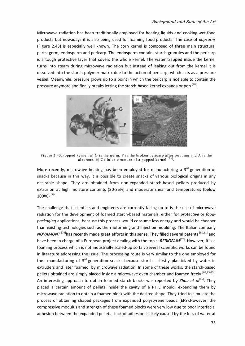
Micr
prod
(Figu
part
is a turn
disso
vess
pres
Fi
Mor
snac
desi
extr
100º
The radi
pack
than
NOV
have
foam
in litthe extr
pelle
An i
plac
micr
proc
com
adhe
rowave radia
ducts but no
ure 2.43) is ts: germ, end
tough prote
ns into steam
olved into thsel. Meanwh
ssure anymo
gure 2.43.Po
re recently, cks because rable shape
rusion at hig
ºC) [70].
challenge thation for the
kaging appli
n existing tec
VAMONT [79]h
e been in ch
ming process
terature add
manufactu
ruders and laets obtained
interesting a
ced a certai
rowave radia
cess of obta
mpressive mo
esion betwe
ation has be
owadays it is
especially w
dosperm and
ective layer m during mi
he starch po
hile, pressure
ore and finall
opped kernel.
aleuro
microwave in this way
e. They are gh moisture
hat scientist
e developme
cations, bec
chnologies shas recently arge of a Eu
s which is no
dressing the uring of 3rd‐gater foamed d are simply approach to n amount o
ation to obta
aining shape
odulus and st
en the expa
een tradition
s also being
well known. d pericarp. Tthat covers icrowave rad
lymer matrix
e grows up to
y breaks lett
a) G is the g
one. b) Cellul
heating has
, it is possib
obtained f
contents (3
ts and engin
ent of foame
ause this pro
such as therm
made great ropean proje
ot industriall
issue. The pgeneration s
by microw
placed insid
obtain foam
of pellets in
ain a foamed
ed packages trength of thnded pellets
nally employ
used for fo
The corn k
The endosper
the whole k
diation but
x due to the
o a point in ting the starc
germ, P is th
lar structure
s been empl
ble to create
from non‐ex
30‐35%) and
eers are cur
ed starch‐ba
ocess would
moforming aefforts in th
ect dealing wly scaled‐up
processing ro
snacks beca
wave radiatio
e a microwa
med starch nside the ca
d block with tfrom expan
hese foamed
s. Lack of adh
B
yed for heati
oaming food ernel is com
rm contains kernel. The instead of le
e action of pwhich the pe
ch‐based ker
e broken per
of a popped
oyed for ma
e snacks of xpanded sta
moderate
rrently facing
ased materia
consume leand injection
his sense. The
with the topi
so far. Seve
oute is very use starch i
n. In some oave oven cha
blocks was vity of a PT
the desired snded polysty
d blocks were
hesion is like
ackground a
ng liquids an
products. T
mposed of th
starch granu
water trapp
eaking out f
ericarp, whic
ericarp is no
rnel expands
icarp after po
kernel [ 78 ] .
anufacturing
various biol
arch‐based p
shear and t
g up to is thals, either foss energy an
n moulding. ey filled seve
ic: REBIOFAMral scientific
similar to this firstly pla
of these wor
amber and foreported by
TFE mould, shape. They yrene beads
e very low du
ely caused by
and State o
nd cooking wThe case of phree main s
ules and the ped inside th
from the ke
ch acts as a ot able to con
s or pop [78].
opping and A
g a 3rd gene
logical origin
pellets prod
temperature
he use of mor protective nd would be
The Italian ceral patents M
[82]. Howev
c works can bhe one empl
sticized by rks, the starc
oamed freely
y Zhou et alexpanding tried to sim
s (EPS).Howe
ue to poor iny the loss of
of the Art
73
wet‐food popcorns tructural pericarp
he kernel rnel it is pressure ntain the
A is the
ration of ns in any duced by s (below
icrowave or food‐ cheaper company [80,81] and
ver, it is a be found loyed for water in ch‐based y [69,83‐85]. [86]. They them by ulate the ever, the nterfacial water at

Chapter
74
the surfa
non‐hom
tempera
paper of
Figure 2
Finally, batters obased p[87].
r 2
ace of the pe
mogeneity d
ature gradie
f Zhou et al i
2.44.a) Expa
it is fair to of starch mix
ellets by ext
ellets. On so
distribution nt between
s shown in F
nded polysty
radiation.c
point out th
xed with wa
trusion. In th
me occasion
of microwav
the sample
Figure 2.44b.
yrene (EPS).b
) Cellular str
hat an intere
ter by micro
his way, a pro
ns, the foame
ves along t
e and the m
. [[69,83,84,85] [86]
b) Starch-bas
ructure of th
esting attem
owave radiat
oduction ste
ed sample bu
he oven ch
mould. A foa]
sed foamed b
e foamed blo
mpt was mad
tion without ep is taken o
urnt in the mamber and med block
lock produce
ock [ 86 ] .
de by Sjöqvipreviously put of the pro
middle due tobecause of
produced in
ed by microw
ist et al to f
producing sta
oduction pro
o the f the n the
wave
foam arch‐ocess

Background and State of the Art
75
2.5.2‐ Starch foams reinforced with natural fibres
Natural fibres proved to reinforce solid starch‐based materials as stated in section 2.4.2.2 where a more detailed description of the production and characterization of starch‐based biocomposites was reported. Nevertheless, their effect on starch‐based foams is still a matter of scientific debate. It is clear that good compatibility exists between cellulose and starch but the high diversity of natural fibres employed in terms of composition and morphology and the different ways of producing and characterizing foams creates certain contradictory results in the topic. This section is focused on describing the main works in literature related to the topic and will give some clues about why there are still doubts about the reinforcement effect of fibres when employed for the production of starch‐based foams.
Table 2.3 shows a list of the most representative scientific works addressing the production of starch‐based foams reinforced with natural fibres in which it is possible to see the great diversity of production routes, natural fibres, and mechanical tests employed to characterize them.
Author Starch Plasticizer Natural fibre Production method
Mechanical tests
Shogren [77] Corn Water Softwood Baking Bending Kaisangsri [88] Cassava Water Kraft fibre Baking Tensile Soykeabkaew [89] Tapioca Water Jute Baking Bending
Flax
Bénézet [90,91] Potato Water Cellulose Extrusion Bending Hemp
Linter cotton
Wheat straw
Lawton [92] Corn Water Aspen Baking Bending Glenn [93] Wheat Water Softwood Baking Bending and
Tensile Corn Tapioca Potato
Cinelli [94] Potato Water Corn Baking Bending
Carr [95] Cassava Water Cassava Baking Bending Wheat
Salgado [96] Cassava Water Softwood
(Eucalypt) Baking Tensile
Mali [97] Cassava Water Sugarcane bagasse
Extrusion Compression
Table 2.3.Starch-based foams reinforced with natural fibres reported in l iterature
In most of these works the matter has not been tackled properly because the inclusion of fibres not only affects the properties of the solid material but also influences the foaming process. The different foaming stages, from nucleation to degeneration of the cellular structure can be affected by their presence. For instance, fibres could induce a heterogeneous nucleation of cells because the available nucleation sites could increase substantially with respect to the pure polymer. This effect can be clearly seen in the work of Soykeabkaew et al in which tapioca starch‐based foams produced by baking are reinforced with different amounts of jute and flax fibre [89].Figure 2.45 shows SEM micrographs of the foams reinforced with different amounts of

Chapter
76
flax‐fibre
lower ce
Figure 2
Well‐adh
the poly
Table 2.
the den
Soykeab
materia
reason b
On the oproduce
shifted uexclusive
this wor
It is kno
strength
When thcontent contrary
not shea
cell grow
Some wthey sta
without observe
fibres ar
due to t
r 2
es. Increasin
ell sizes, a ph
2.45. Starch f
hered fibres ymer matrix 3 could not
nsity of the
bkaew et al l was reinfor
behind the im
other hand, ed slight incr
up from 302
ely in terms rk which is bwn that the
h [88].
he foams are
increases a
y, density us
ar effects as wth was avoi
works reporte
art to agglom
fibres that
d in Figure 2re observed
he agglomer
ng the amou
henomenon
foams produc
a) 0 w
are also abl
and as a re
be analysed
e foams pr
the density rced with a mprovement
in the work rements of t2 MPa to 117
of the dens
ased on the presence of
e produced balthough no
ually increas
in extrusionided by high
ed that there
merate and mt represent 2.46 in whic
. The tray re
ration of fibr
nt of fibres usually linke
ced by baking
wt%. b) 1 wt%
e to induce cesult, in its c
d exclusively
oduced also
increased f
10 %wt of bt in mechanic
of Kaisangsrthe density, 70 MPa. Thi
ity variation
lower absor
f water plast
by extrusionconsistent
ses with fibre
n foaming an
er viscosities
e is an optim
mechanical pweak point
h baked sta
einforced wi
res.
resulted in hed to heterog
g and reinfor
%. c) 5 wt%.
changes in tcapability of y in terms of
o varied. Fo
rom 0,2 g/c
both, jute an
cal propertie
ri et al, the re
from 0.12 ts drastic inc
. Neverthele
rption of wat
ticizes the sta
n foaming thexplanation
e content in nd it seems ts of the poly
mum in the aproperties dts under m
rch trays rei
th 40wt% o
higher popu
geneous nuc
rced with dif
d) 10 wt% [ 8
he viscosity
expansion. f the reinfor
or instance,
cm3up to mo
nd flax fibres
es obtained b
einforcemen
o 0.15 g/cm
crement of sess, an additi
ter of the sa
arch polyme
e density se
n was found
baking proc
that the only
mer matrix.
mount of fibecrease due
echanical lo
inforced wit
f fibres pres
lations of ce
leation mech
ferent amoun89] .
and rheolog
Some of the
cing effect o, in the pr
ore than 0.3
s. This could by adding fib
nt with 40 %w
m3, while the
trength cann
ional explana
mples reinfo
r matrix resu
ems to decr
d for this re
cesses. In thi
y possible ex
bres used. Be
e to the appe
oads[92].This h different asent regions
ells and henc
hanisms.
nts of flax-fib
gical behavio
e works liste
of fibres bec
revious wor
3 g/cm3when
be the prin
bres.
wt of Kraft fe tensile stre
not be expla
ation arose orced with fiulting in a lo
rease as the esult [90]. On
is case, there
xplanation is
eyond this vearance of aphenomeno
amount of aof higher cl
ce, in
bres:
ur of ed in cause rk of n the cipal
ibres ength ained from bres.
oss of
fibre n the e are that
alue, areas on is spen larity

Figu
In ot
not was poly
avai
mat
In adue dete
cons
deal
poss
The on tthe plas
proc
only
pack
such
obta
mec
foam
app
cons
baki
for
ure 2.46. Ba
ther works tkept consta
mentioned ymer matrix
lable to exp
rix and its ca
ddition, few
to the poo
ermining the
sidered in m
ling with st
sible. This is
2.5.3‐ Sum
first parts othose mecha
stabilization
ticizer and t
cesses of sta
y application kaging (loos
h as plates aained are ve
chanical perf
ming proces
roach becau
sumption is ing. Some wpackaging a
aked starch tr
the analyses nt [93,94,96]. Th
previously, . Hence, var
pand the po
apability of s
w works perfo
or homogen
e mechanical
most of the tarch reinfor
one of the a
mmary
of section 2.5anisms which
n mechanism
the blowing arch‐based m
found for fose‐fill chips) and trays can
ery inhomoge
formances thsses. In this use it is ba
lower than
orks reporte
applications
rays reinforce
w
of the result
he fact of ke
is the blow
rying this ra
lymer matri
upporting th
ormed a det
neity of the
l properties papers. Ano
rced with fi
reas explore
5 dealt with h are mainly
m which dep
agent. The materials: exoams produc
because the
n be produce
eneous. Hen
han the exist
sense, mic
ased on a vn with tradi
ed the produ
but the me
ed with diffe
wt%. c) 40 wt
ts is not clea
eeping this ra
wing agent a
atio could a
x and on th
he pressure g
tailed charac
e structures of cellular m
other impor
ibres foame
ed in this res
the fundam
y affected by
pends on th
following se
xtrusion foaced from extey cannot b
ed by bakingnce, the pro
ting ones de
crowave foavolumetric hitional foam
uction of star
echanical pro
B
erent amounts
% [ 92 ] .
ar simply bec
atio constan
and at the s
ffect on the
he other han
generated by
cterization oobtained.
materials suc
tant aspect ed using mi
earch.
mentals of foy the proper
he fact that ection (2.5.1
aming, bakintrusion foame reshaped g (section 2.oduction of spends on thming (sectio
heating of t
ming routes rch foams by
operties obt
ackground a
s of aspen-fib
cause the rat
t is importan
same time t
e one hand,
nd, the visco
y steam with
of the cellula
Moreover, a
h as the ope
is that find
crowave he
aming starch
ties of starc
water plays
) describes t
ng and micro
ming(section 2after foamin
5.1.2) but thstarch‐based
e developme
on 2.5.1.3) the sample. such as ext
y microwave tained were
and State o
bres: a) 5 %w
tio starch/wnt because w
the plasticize
, the amoun
osity of the hout collapsi
ar structure an importan
en cell conte
ding scientifi
eating has n
h, especially
h. This is the
s a dual rol
the main pr
owave foam2.5.1.1) is prng. Shaped he cellular st
d foams with
ent of more
represents Moreover,
trusion foam radiation to
e poor. One
of the Art
77
wt. b) 20
water was water, as er of the nt of gas
polymer ng.
probably nt factor ent is not c papers
not been
y focused e case of e as the oduction
ming. The rotective‐products tructures h greater
efficient the best energy
ming and o be used
possible

Chapter 2
78
reason is that these foams were obtained from solid TPS pellets which did not adhere properly after their expansion[86].
One of the works included in this thesis (chapter 4) proposes an interesting alternative based on the production of foamed blocks by microwave radiation from thermoformed sheets. Moreover, natural fibres were employed to increase the mechanical properties of the foams produced regarding stiffness and strength. In spite of having found a significant amount of works in which starch‐based foams are reinforced with natural fibres (section 2.5.2), there are not many pieces of work reporting on this kind of reinforcement in microwave foaming processes.
The revision of the state of the art carried out in this section helps to set the objectives of the thesis regarding the development of starch‐based foams(section 1.3.1).Moreover, this revision has been very useful in order to detect which points require further research in order to develop these materials for the production of more sustainable foams. A more detailed description of the state of the art concerning this topic will be found in the works included in this thesis (chapter 4).

2.6‐
The perf
the deve
perf
rese
foam
core
Desp
emp
the as a The bar)
poly
chai
hand
obta
seco
The of Presis
and low‐
The whe
poly
Polypropyle
production formance of
synthesis o
elopments i
formed durin
earch, this se
ms: from the
e in sandwich
pite the few
ployed polym
polyolefin g derivative opolymerizat
) and tempe
ypropylene w
in. When th
d, when the
ained. In the
ond case, the
isotactic ve
P extended stant, as we
proved to h‐density poly
Figure2.47.
main drawb
ere high imp
ymer chain
ene‐based fo
of polyprop
this polyme
of new poly
n this field ng this thesis
ection will pe basics of thh panels.
w application
mers in the mgroup of poly
of the petrole
tion reaction
eratures betw
with several
ey are rand
y are distrib
first case they are altern
rsion of the worldwide bll as PE, but
have greater
yethylene (LD
a) Propylene
back of isotacpact strengt
brought abo
oams
pylene foams
er. However,
propylene g
without th
s constitutes
rovide the rhe polymer t
ns of polypr
market due tymers becau
eum fraction
n is carried ween 30 an
steric conf
domly distrib
buted in an oe methyl gro
atively place
PP polymer because it wa
t with better
r thermal sta
DPE).
e monomer. b
ctic PP is its ths are requ
out the dev
s has been , the resear
grades perm
e necessity s one of them
reader with tto the applic
ropylene (PP
to its outstan
use propylen
nation, is the
out by Zieglnd 80 ºC. Th
figurations d
buted, atactorderly way oups are plac
ed on both si
chain increa
as a cheap tr mechanica
ability. More
b) Isotactic p
low ductility
uired. The i
velopment o
B
somewhat l
ch conducte
mitted the a
of crosslink
m. In order tthe main co
ation of PP f
P) as a foam
nding prope
ne, an unsatu
e constituent
ler and Natthe side meth
depending o
tic polypropyisotactic and
ced in the sa
ides.
ased its crist
hermoplasti
l properties eover, its de
olypropylene
y which prev
ntroduction of PP‐based
ackground a
imited due t
ed during the
appearance king the pol
to understan
ncepts relat
foams as a re
m, it is one rties and low
urated alken
t monomer ota catalyst a
hyl groups (
n their posi
ylene is obt
d sindiotactiame side of t
tallinity subst
c, electric ins
regarding st
ensity is even
e and syndiot
ents it being
of ethylene
copolymers
and State o
to the poor e last few y
of some int
lymer. The nd the novel
ted to polyp
ecyclable lig
of the mos
w price. It be
ne or olefin of the polym
at low pressu
Figure 2.47)
ition in the tained. On t
tic polypropythe chain wh
stantially and
sulator and trength and n lower than
tactic copoly
g used in app
e monomer
s which in
of the Art
79
foaming ears and teresting research ty of this ropylene htweight
st widely elongs to obtained er chain. ures (1‐5 ) provide polymer
he other ylene are ile in the
d the use chemical stiffness
n that of
ymer.
plications rs in the turn are

Chapter
80
denomin
the chai
2.
The pro
polymer
shape o
similar t
introduc
can be agents) the molt
There ar
foaming
dissoluti
such as objectiv
properti
product
mouldin
Extrusio
it is a co
screws a
transfer
extruder
from the
shaft dim
obtained
r 2
nated as rann, or block c
.6.1‐ Polypro
duction of p
r employed, of the produ
to that used
ced into the introduced or by direct
ten polymer
re lot of the
g, extrusion fion [98]. Som
rotomolding
e is to reduc
ies. This se
ion of med
ng and bead f
2.6.1.1‐ Ex
on foaming isost‐effective are delibera
red to the p
r. Moreover
e entrance tmensions [2].
d such as she
Fi
ndom copolycopolymers,
opylene foam
polyolefin fo
by the dens
uct [3]. Most d for the pro
system mak
either by t
ly dissolving .
ermoplastic ffoaming, com
me of them a
g and injectice weight an
ction is esp
ium and low
foaming.
xtrusion foam
s technology
and continu
tely designe
polymer rap
r, the pressu
o the exit du
The main deets, profiles
igure 2.48. F
ymers, when
when they a
ming process
oams, such a
sity and prop
of these fo
oduction of s
king the con
thermal dec
a gas or a lo
foaming pro
mpression mare focused on moulding
d at the sam
pecially focu
w density P
ming
y that posses
uous process
ed to have a
pidly, which re of the poue to the scr
isadvantage s and tubes a
Foamed produ
n the ethyle
are placed in
ses
as those bas
perties requ
oaming proce
solid parts b
ntrol of para
composition ow boiling p
cesses such moulding and
on the pro
g, which are
me time to mused on tho
PP foams su
sses several s with high oa large surfa
melts only
olymer/blow
rew design wof the proce
as shown in
ucts obtained
ene monome
an orderly w
sed on PP, is
uired for the esses emplo
but differ in meters mor
of solid pa
oint liquid (p
as rotomold
d batch‐foamduction of m
mainly used
maintain a ce
ose processe
ch as extru
advantages,
output rates
ace‐to‐volum
a few secon
ing agent sy
which can be
ess is that on
Figure 2.48.
d by extrusion
er is random
way.
s conditione
final applica
oy technolog
the fact tha
e complex [2
articulates(ch
physical blow
ding, injectioming processmedium‐high
d for applica
rtain level oes common
usion foami
the principa
. In terms of
me ratio allo
nds after be
ystem increa
e controlled nly simple ge
n foaming.
mly located a
d by the kin
ation and by
gy, which is at a gas pha2]. The gas phemical blowing agents)
on molding, bses based on
h density fo
ations where
of the mecha
nly used for
ing, compres
al one being
f processing
owing heat t
eing fed into
ases substan
by the flight
eometries ca
along
nd of y the very
ase is phase wing ) into
bead n gas ams,
e the nical
r the ssion
that g, the o be
o the tially t and an be

The shap
agen
extr
blow
and main
redu
scre
one ratio
befo
whic
high
foam[2,99,1
This
mat
expa
also
This
have
Figu
and deco
unti
time
common sta
ping (foamin
nt employed
ruder barrel wing agents,
the tempera
n drawback uce its visco
ew continues
single extru
os) in order ore foaming.
ch allows thh temperatu
ming. After c100].
s process wa
erials, espe
ands after ex
be applied f
2.6.1.2
s is a batch‐fe previously
ure 50. Henc
it is only omposing thl the momen
e in which pr
ages in extru
ng). The po
d. In the cas
through a p
, the blowin
ature is raise
of extrusion
sity and ma
s transferring
uder machin
to give eno
. For this rea
e first extru
res and the
cooling, the s
as also expla
cially in the
xiting the die
for polyolefin
2‐ Compressi
foaming proc
y been dispe
e, in this pro
applied (P0
e blowing ag
nt in which pressure is ap
usion foamin
olymer‐gas m
se of physicpump and m
g agent is m
ed enough to
n foaming is ke it adequa
g heat to the
ne, the lengt
ough time to
ason, it is us
der to be e
second one
stabilized ga
Figure 2.49
ained in secte last stage
e. Figure 2.3
n foams.
on moulding
cess whose ersed throug
ocess pressu
0→P) with t
gent (T Td) apressure is rpplied is cons
ng are polym
mixing stage
cal blowing mixed with th
mixed with t
o decompose
how to diss
ate for foam
e system unt
th of the ex
o the polymsually prefera
mployed to e, set at low
s/melt syste
9.Tandem ex
tion 2.5.1.1es (expansio
39 shows an
g
main feature
ghout the po
ure is not ne
the purpose
and holding aeleased (P→siderably sho
B
er melting, e differs dep
agents the he molten p
he polymer e the blowin
sipate the he
ming. This pro
til the end otruder barre
mer/blowing
able to use tmix the pol
w temperatu
em is pumpe
xtrusion syste
focussing on
n and stabi
evolution of
e is the use
olymer in a eeded for dif
e of transfe
all the gas pr
→P0) and exp
orter than in
ackground a
polymer‐gas
pending on t
gas is fed in
polymer. In t
at the entra
ng agent and
eat from the
ocess is chal
of the barrel.
el has to be agent mixtu
tandem equ
ymer with tures to cool
d into a shap
em.
n what happ
ilization) in f the cellular
of chemical melt‐blendin
ffusing the gerring heat roduced into
ansion takes
n batch foam
and State o
s mixing, coothe kind of n the middl
the case of ance of the
d generate ga
e molten po
llenging bec
. In the case
very high (
ure to dissip
uipment (Figu
the blowing l the mixtur
ping unit for
pens to starc
which the r structure w
blowing age
ng step as s
gas into the to the co
o the molten s place. The
ming process
of the Art
81
oling and blowing
le of the chemical extruder
ases. The olymer to
ause the e of using
high L/D pate heat ure 2.49) agent at e before foaming
ch based polymer
which can
ents that shown in polymer
mpound, polymer effective es based
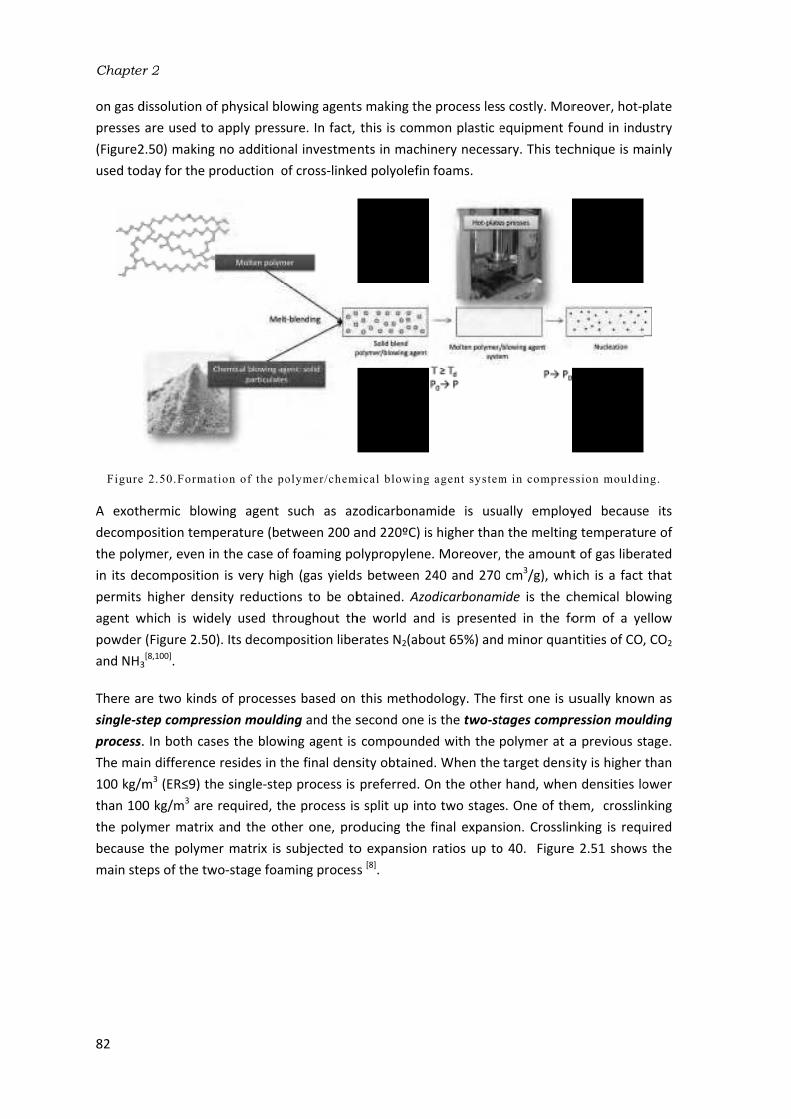
Chapter
82
on gas dpresses (Figure2
used tod
Figure
A exoth
decomp
the poly
in its de
permits agent w
powder and NH3
There ar
single‐stprocess.
The mai
100 kg/m
than 100
the poly
because
main ste
r 2
dissolution of
are used to 2.50) making
day for the p
e 2.50.Format
hermic blow
position temp
ymer, even inecomposition
higher dens
which is wid
(Figure 2.50
3[8,100].
re two kinds
tep compres
. In both cas
n difference
m3 (ER≤9) th0 kg/m3 are ymer matrix e the polyme
eps of the tw
f physical blo
apply press
no addition
production o
t ion of the po
wing agent perature (be
n the case of
n is very hig
sity reductio
ely used thr
0). Its decom
s of processe
ssion mouldi
ses the blow
e resides in thhe single‐ste
required, thand the oth
er matrix is wo‐stage foam
owing agents
ure. In fact, nal investme
of cross‐linke
olymer/chem
such as az
tween 200 af foaming po
h (gas yields
ons to be ob
roughout th
position libe
es based on ing and the s
wing agent is he final dens
p process is he process isher one, pro
subjected toming process
s making the
this is comm
nts in machi
ed polyolefin
mical blowing
zodicarbonam
and 220ºC) isolypropylene
s between 2btained. Azo
he world and
erates N2(abo
this method
second one icompounde
sity obtained
preferred. Os split up int
oducing the o expansion s [8].
e process les
mon plastic einery necess
foams.
g agent system
mide is usu
s higher than
e. Moreover,
240 and 270
odicarbonam
d is present
out 65%) and
dology. The is the two‐sted with the d. When the On the other
o two stages
final expans
ratios up to
s costly. Mor
equipment fary. This tec
m in compres
ually employ
n the melting
the amount
cm3/g), wh
mide is the c
ted in the fo
d minor quan
first one is utages compr
polymer at atarget dens
r hand, when
s. One of the
sion. Crosslin
o 40. Figure
reover, hot‐pfound in indu
chnique is m
ssion mouldin
yed because
g temperatu
t of gas liber
ich is a fact chemical blo
orm of a ye
ntities of CO,
usually know
ression moul
a previous st
ity is higher n densities loem, crosslin
nking is requ
e 2.51 shows
plate ustry ainly
ng.
e its re of
rated that
wing ellow , CO2
wn as lding tage. than
ower nking uired s the

The poly
liqui
prod
diffe
bein
agen
need
facts
Fig
Poly
tem
one two expa
obta
2.6.1.3
bead‐foami
ypropylene (
id blowing aduct is obta
erence with ng impregna
nt in PP und
ded due to ts make EPP f
gure 2.52. a)
ypropylene c
peratures. Tto the melt
temperatur
ansion but aining a certa
F
3‐ Bead‐foam
ing process (EPP). In thi
agent, are lat
ined inside respect to tted with the
er atmosphe
the high me
foams more
Moulded-bea
copolymers The lower on
ting of propy
res. In this w
also their a
ain degree o
Figure 2.51.
ming.
has been t
s process, p
ter expande
moulds whe
the process we blowing ag
eric pressure
elting tempe
expensive th
ad process. b
are employ
ne correspon
ylene monom
way, one pa
dhesion wh
of melt streng
Two-stage fo
raditionally polypropylen
d by heating
ere the exp
with PS is thgent becaus
e. Moreover,
erature of PP
han EPS [101].
) Moulded ex
structure [1
yed in this p
nds to the mmers. The foart of the P
hile the othe
gth during ex
B
oaming proce
employed f
ne beads, p
g with steam
anded bead
hat PP beads
se of the hig
, high steam P, generally
xpanded bead102] .
process bec
elting of eth
oaming temp
P beads are
er part is n
xpansion.
ackground a
ess [ 8 ] .
for the prod
reviously im
m. The final ss are fused
s have to be
gh diffusion temperatur
between 150
ds (EPP) and
ause they p
hylene mono
perature is se
melted allo
ot melted, w
and State o
duction of e
mpregnated shape of the
together. T
e expanded jrate of the
res and press
0 and 170ºC
d SEM image
present two
omers and thet up betwe
owing not o
which is the
of the Art
83
expanded with the
e foamed The main just after
blowing sures are C. These
of their
melting he higher en these
only their e key to

Chapter 2
84
2.6.2‐ Polypropylene foams in the market: development of branched polypropylenes
Polypropylene has been considered for foaming applications because it is an ideal candidate to replace more common thermoplastics used in this field such as polystyrene (PS) and polyethylene (PE). The reasons are mainly two. Firstly, the higher stiffness and strength of PP with respect to PE and secondly, the higher impact strength with respect to PS. This is because PP at ambient temperature is rubbery while PS is glassy (The Tg of PS is 105ºC). Moreover, the low heat‐deflection temperatures of PE and PS makes their foamed counterparts non suitable in high‐service temperature applications. For instance, PS foams when heated above its Tg soften and deform.
Several foamed products based on conventional grades of PP have been developed and launched on the market. The main example is expanded polypropylene (EPP), which is used as a shock energy absorber in automotive applications [103]. It is produced by the bead foaming process previously explained in section 2.6.1.3. The stiffness of the final foamed parts produced from EPP is low in comparison with other materials employed for structural applications such as PVC and PET. There are several reasons for this but the principal one is that polypropylene copolymers are usually employed in this foaming process because they are tough rather than stiff. EPP is currently being produced by companies such as BASF [104] and JSP [105].
The production of polypropylene foams from isotactic grades is a challenging task because of their low melt strength linked to their linear architecture and low viscosity in the molten state. Branching is another interesting alteration of the PP chain architecture that allows this polymer to be used for foaming applications. In 1990, BASELL launched the first grade of high melt strength (HMS) PP which was based on a branched PP. This alteration of the chain architecture is generally achieved by subjecting the polymer to electron irradiation under a poor O2
atmosphere[3]. Branched PPs are able to reach higher expansion than linear PPs due to the strain hardening phenomenon which is based on a sudden increase of the extensional viscosity produced by the entanglement of the polymer chains when they are subjected to high strains as in a foaming process. Extensional viscosity measurements are usually performed in order to quantify the strain hardening phenomenon. Typical extensional viscosity curves are shown in Figure 2.53 in which the different behaviours of a linear PP and a branched PP are clearly observed. In the case of the branched PP the extensional viscosity (ηE) is drastically increased even at the highest strain rate (1.0 s‐1).

The Sinc
has poo
whic
The of mult
also
nucl
prop
whic
disp
The nano
are high
in po
whe
ρblen
part
the conc
Fig
first foamed
ce then, the spread wor
r cellular str
ch also reduc
2.6.3‐ Foa
combination
cellular ma
tifunctional able to prom
leation, exp
perties of th
ch in turn persions alon
nucleation ooclays. The hmore prono
her surface/volymers rein
ere w is the w
d is the dens
ticle. This las
number of pcentration of
gure 2.53.Ext
d sheet base
production rldwide. How
ructures of laces the stiffn
amed polypr
n of foaming
aterials: pol
role because
mote signific
ansion and he foams pro
are depend
ng the polym
of cells durin
heterogeneo
ounced with volume ratio
nforced with
weight fract
sity of the po
st term accou
potential nuc
f nanopartic
tensional vis
ed on a bran
of PP foams
wever, the f
arge cell size
ness and stre
ropylene nan
g technology
lymer nano
e they not ocant alteratio
stabilization
oduced are dent on the
er matrix as
ng the first st
ous nucleatio
nanoparticle
. Equation2.
fillers [110].
ion of the pa
olymer conta
unts for the icleating sites
les (w).
scosity curve
nched polypr
s obtained frfoamed shee
es with cells
ength in the t
nocomposite
y and polyme
ocomposite only enhance
ons of the fon can be af
subjected to
e degree o
mentioned
tages of foa
on mechanis
es than with
10 shows ho
=article in the
aining the pa
influence of s increases. T
B
s. a) Linear P
ropylene wa
rom branche
ets produce
typically or
thickness dir
es
er nanocomp
foams, in
e the proper
aming proce
ffected by t
o changes in
of polymer‐nin section 2.4
ming could bsms usually a their micro
ow to calcula
= e composite,
article and Vthe filler size
The same th
ackground a
PP. b) Branch
s produced ed PP or mix
d by extrusi
iented in the
rection [107‐10
posites gave which na
ties of the sess. The diffe
heir presenc
nduced in th
nanoparticle
4.2.3 [56].
be influence
associated wmetric count
ate the avail
, ρp is the de
Vp is the volu
e. When dec
ing happens
and State o
hed PP.
by DOW in xtures with ion foaming
e extrusion 09].[107,108,109
place to a nanoparticles olid materia
erent foamin
ce. In this w
he cellular s
e adhesion
d by the pre
with the use terparts due
lable nucleat
ensity of the
ume of the increasing the when increa
of the Art
85
1994[106]. linear PP
g present direction
new class play a
al but are g stages: way, the tructure, and the
esence of of fillers
e to their ting sites
.
particle, ndividual filler size asing the

Chapter 2
86
What happens during the nucleation stage should be reflected in the cellular structure morphology. Normally, the population of cells increases on adding nanofillers. For instance, the cell density (cells/cm3) of polypropylene based foams reinforced with nanoclays strongly increased with the addition of 7.5 wt% of nanoclays [111]. For this reason, the use of nanofillers is also implemented as a common strategy for the production of microcellular foams. Moreover, the nanoparticle dispersion influences to a great extent the cellular structure morphology. The nucleation rates of exfoliated nanocomposites proved to be higher than those of intercalated nanocomposites, which is attributed to the fact that at the same nominal particle concentration, the effective particle concentration is higher for well dispersed nanoparticles [112].[113,114,115]
The expansion process is also affected by the presence of nanoclays because the elongational viscosity of the polymer matrix can be increased. Even in some cases, nanoclays induce the presence of strain‐hardening phenomenon [113‐115]. In addition, nanofillers based on platelet geometries such as nanoclays act as a barrier against gas diffusion avoiding blowing agent loses during the expansion process [112].The fire retardant properties of polymer foams are also improved by incorporating nanofillers due to the formation of a char during burning, which avoids further propagation of flames [112].
The cell wall thickness of microcellular polymer foams is in the range of microns or even submicrons. This fact makes nanofillers an ideal reinforcement because they can be allocated within the cell walls, edges and struts without breaking them during the expansion process. This reinforcing effect has been proved in several publications [112,116].
In the particular case of polypropylene, the research currently being conducted is especially focused on the effect that nanoclays have on the branched structure of HMS polypropylenes. When linear polypropylenes are employed the cellular structure homogeneity tends to increase due to a higher nucleation rate and to the appearance of strain hardening in some cases. On the contrary, when using branched polypropylenes these effects are not so clear and it was even stated that branches avoid an effective intercalation of the polymer between the clay layers [117]. Despite the unclear results, some works reported improvements in the cellular structure and enhancements in the mechanical properties by the addition of nanoclays to blends of HMS PPs and linear PPs [118]. These kinds of blends are usually produced for foaming applications of PP due to the higher cost of HMS PPs with respect to linear PPs. Moreover, the addition of nanoclays to the same kind of blends proved to broaden their foaming window due to an increase of their thermal resistance in the molten state [119].
2.6.4‐ Practical use of polypropylene foams as the core of sandwich panels
Low‐density PP foams could be used as the core of sandwich panels due to the high stiffness and strength of the solid matrix but their cellular structure has to be improved in order to reach the performance of common foamed cores employed in the market such as PVC foams. Sandwich panels are light structural materials composed of thin solid skins separated by a thicker lightweight rigid core. The role of the core is to increase the inertia moment of the panel without substantially increasing the weight. Figure 2.54 shows an analogy between a sandwich panel

with
load
load
shea
Fig
The core
opti
at t
pane
equa
(P) [1
The resp
para
in thof th
foam
Curr
and such
hydr
that
h a foamed cds. In the m
ds, in the sam
ar loads, as t
gure 2.54.a)
mechanical e material an
mization pro
he same tim
el under a loation 11 in w1].
second term
ponse of the ameter that he first term
he first term
med core in t
rently, the choneycomb
h as in the hrophobicity t prevent the
core and a mmetallic l‐bea
me way as ththe foamed c
Analogy betw
behaviour ond on its ge
oblem in wh
me the cons
oad P in thre
which δ/P re
m of equatio
panel. It is pmainly influe
. However, im is quadrat
the sandwich
ore of sandw
bs (Figure 56)
hulls of yach
are importa
e entrance o
metallic l‐bea
m the flang
he skins of thcore is [120].
ween sandwi
thre
of a sandwich
eometry. Th
ich the goal traints impo
ee point ben
epresents th
=
Figure 2.55.
n 10 accoun
possible to se
ences its res
n both term
ic with the h panel beha
wich panels
). PVC foams
ts or boats wnt requirem
of water to t
am because ges are subj
he sandwich
ich panel and
e-point bend
h panel depe
he design of is to design
osed by stiff
nding (Figure
he deflection
= +
. Sandwich p
nts for the co
ee how the ssponse. The
ms the core thcore thickne
aviour [1].
are made os, for instanc
where apart
ments. The P
the structur
B
both behave
ected to in‐panel are. H
d l-beam. b) S
ding load.
ends on the a sandwich
the panel wfness and st
e 2.55), its mn of the beam
+
anel dimensi
ontribution oshear modul
compressive
hickness app
ess. This fac
of PVC, SAN,
ce, are freque
t from mech
PVC foams p
e. The main
ackground a
e in a similar
‐plane comp
However, the
Sandwich pan
properties o panel can b
ith the minim
trength. Con
mechanical bm (δ)divided
ions.
of the foame
us of the foa
e modulus of
pears(c). Inde
t reflects th
PET and PU
ently used inhanical prope
resent close
drawback o
and State o
r way under
pression and
e web is subj
nel behaviou
of the solid sbe formulat
mum weight
nsidering a s
behaviour is d by the app
ed core to thamed core (Gf the skin (Efeed, the dep
e importanc
U foams, bal
n marine app
erties, buoya
ed cellular st
of rigid PVC
of the Art
87
bending d tension jected to
r under
skins and ed as an
t fulfilling sandwich given by lied load
e overall Gc) is the
f)appears pendency ce of the
lsa wood plications ancy and tructures foams is
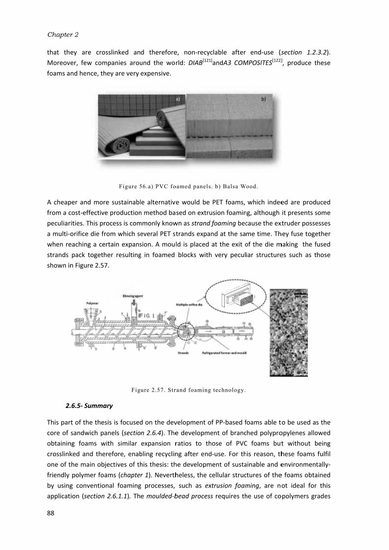
Chapter
88
that th
Moreov
foams a
A cheap
from a cpeculiar
a multi‐owhen re
strands shown in
2.
This par
core of obtainin
crosslink
one of tfriendly by using
applicat
r 2
ey are cro
er, few com
nd hence, th
per and mor
cost‐effective
rities. This pr
orifice die freaching a ce
pack togeth
n Figure 2.57
.6.5‐ Summa
rt of the thes
sandwich pa
ng foams w
ked and the
the main obj
polymer foa
g conventio
ion (section
sslinked an
mpanies arou
hey are very
Figure 5
e sustainabl
e production
rocess is com
rom which se
rtain expans
her resulting
7.
Fig
ary
sis is focused
anels (sectiowith similar
refore, enab
jectives of thams (chapternal foaming
2.6.1.1). Th
d therefore
und the wor
expensive.
56.a) PVC fo
e alternative
n method ba
mmonly know
everal PET st
sion. A moul
g in foamed
ure 2.57. Str
d on the dev
n 2.6.4). The
expansion r
bling recyclin
his thesis: thr 1). Neverth
g processes, e moulded‐b
e, non‐recyc
rld: DIAB[121
oamed panels
e would be sed on extru
wn as strand trands expa
ld is placed blocks with
rand foaming
velopment oe developme
ratios to th
ng after end
he developm
heless, the csuch as ex
bead process
clable after ]andA3 COM
. b) Balsa W
PET foams, usion foamin
foaming bec
nd at the sa
at the exit oh very pecul
technology.
of PP‐based fent of branc
hose of PVC
d‐use. For th
ment of susta
cellular struc
xtrusion foams requires th
end‐use (s
MPOSITES[122]
ood.
which indee
ng, although cause the ext
me time. Th
of the die miar structure
foams able tched polypro
C foams but
his reason, th
ainable and ectures of the
ming, are no
he use of co
section 1.2.], produce t
ed are prod
it presents sxtruder posse
hey fuse toge
making the fes such as t
to be used as
opylenes allo
t without b
hese foams environment
e foams obta
ot ideal for
opolymers gr
.3.2). these
uced some esses ether fused hose
s the owed being fulfil tally‐ained r this rades

Background and State of the Art
89
which are not as stiff nor strong as conventional photopolymers (section 2.6.1.3) and the compression moulding route requires crosslinking the polymer matrix with the aim of achieving foams with high expansion ratios and with a defined shape (section 2.6.1.2). All these facts make the improved compression moulding (ICM) route developed at CellMat Laboratory and described in chapter 3, a promising foaming process to be employed for the production of rigid low‐density PP foams. Chapter 5 will show results confirming that the cellular structures and the mechanical properties obtained from this process are at least comparable to those of the PVC and PET foams currently employed in the market. In addition, Chapter 6 will show a comparison between these materials and the PP foams developed in this thesis.
Last but not least, the use of nanoclays could represent an additional contribution to the target of obtaining PP foams with better cellular structures. There are some works in literature dealing with this topic (section 2.6.3) whose results suggest that both the cellular structure and the mechanical properties of PP foams can be improved with their addition. Nevertheless, there are lot of doubts still remaining about how nanofillers interact with the foaming process of polymers. One of the works carried out (chapter 5) shows some interesting results which can contribute to increasing the knowledge existing so far about the effect of nanoclays on the production and properties of polymer foams.
The state of the art performed here settled the objectives of the thesis in this topic. They were listed in section 1.3.2. Besides, a more detailed description of the state of the art will be found in each one of the works based on the development of PP foams included in this thesis (chapter 5).

Chapter 2
90
References [1] Gibson, L.J. and Ashby, M.F. Cellular Solids: Structure and Properties. 2th ed. Cambridge University
Press, Cambridge. 1997. [2] Lee, S.T.; Park, C.B. and Rajesh, N.S. PolymericFoams. Science and Technology. Taylor and Francis
Group. 2007. [3] Klempner, D. and Frisch, K.C. Handbook of polymeric foams and foam technology. Hanser
Publishers. 1991. [4] Reglero‐Ruiz, J.A.; Viot, P. and Dumon, M. Foaming behaviour and compressive properties of
microcellular nanostructured polystyrene. Cellular polymers. 28, 363‐386. 2009. [5] Chow, T.S. Molecular interpretation of the glass transition temperature of polymer‐diluent
systems. Macromolecules. 13, 362‐364. 1980. [6] Elliott, J.A.; Windle, A.H.; Hobdell, J.R.; Eeckhaut, G.; Oldman, R.J.; Ludwig, W.; Boller, E.; Cloetens,
P. and Baruchel, J. In‐situ deformation of an open‐cell flexible polyurethane foam characterised by 3D computed microtomography. Journal of Materials Science.37, 1547‐1555. 2002.
[7] Rodriguez‐Perez, M.A. Crosslinked polyolefin foams: Production, structure, properties and applications. Advances in Polymer Science. 184, 97‐126. 2005.
[8] Hidalgo, F. Diseño Optimizado de los Parámetros de Proceso en la Fabricación de Espumas de Poliolefina Reticulada mediante Moldeo por Compresión. Tesis Doctoral. Universidad de Valladolid. España.2008.
[9] Christensen, R.M. Mechanics of low density materials. Journal of the Mechanics and Physics of Solids.34, 563‐578. 1986.
[10] Zhu, H.X.; Knott, J.F.; and Mills, N.J. Analysis of the elastic properties of open‐cell foams with tetrakaidecahedral cells. Journal of the Mechanics and Physics of Solids. 45, 319‐343. 1997.
[11] Warren, W.E.; Kraynik A.M. Foam mechanics: The linear elastic response of two dimensional spatially periodic cellular materials. Mechanics of Materials.6, 27‐37. 1987.
[12] Rodriguez‐Perez, M.A. Propiedades térmicas y mecánicas de espumas de poliolefina.Tesis Doctoral. Universidad de Valladolid. 1998.
[13] Timoshenko, S. and Goodier, J.N. Theory of elasticity. Mc‐Graw Hill. 1951. [14] Weller, J.E. and Kumar, V. Solid‐State Microcellular Polycarbonate Foams. II. The Effect of Cell Size
on Tensile Properties. Polymer Engineering and Science.50, 2170‐2175. 2010. [15] Rodriguez‐Perez, M.A.; Lobos, J.; Pérez‐Muñoz, C.A. and de Saja, J.A. Mechanical response of
polyethylene foams with high densities and cell sizes in the microcellular range. Journal of Cellular Plastics.45, 389‐403. 2009.
[16] Rodriguez‐Perez, M.A.; Lobos, J.; Pérez‐Muñoz, C.A. and de Saja, J.A. Mechanical behaviour at low strains of LDPE foams with cell sizes in the Microcellular range. Advantages of using these materials in structural elements. Cellular Polymers. 27, 347‐362. 2008.
[17] Huber, A.T. and Gibson, L.J. Anisotropy of polymer foams. Journal of Materials Science.23, 3031‐3040. 1988.
[18] Mehta, B.S. and Colombo, E.A. Mechanical properties of foamed thermoplastics. Journal of Cellular Plastics.12, 59‐66. 1976.
[19] Gupta, S; Watson, B.; Beaumont, P.W.R. and Ashby, M.F. Final Year Project. Cambridge University Engineering Department. Cambridge. UK. 1986.
[20] Hilyard, N.C. Mechanics of Cellular Plastics. McMillan Publishing CO.London. 1982. [21] Thomson, W. (Lord Kelvin).On the division of space with minimum partitionalarea. Philosphical
Magazine.24, 503‐514. 1887. [22] Sullivan, R.M.; Ghosn. L.J. and Lerch, B.A.A. General tetrakaidecahedron model for open‐celled
foams. International Journal of Solids and Structures.45, 1754‐1765. 2008. [23] Sullivan, R.M. and Ghosn, L.J. Shear moduli for non‐isotropic, open cell foams using a general
elongated Kelvin foam model. International Journal of Engineering Science.47, 990‐1001. 2009.

Background and State of the Art
91
[24] Gong, L.; Kyriakides, S; and Jang, W.Y. Compressive response of open cell foams. Part I: Morphology
and elastic properties. International Journal of Solids and Structures.42, 1355‐1379. 2005. [25] Kalia, S.; Kaith, B.S. and Kaur, I. Cellulose fibres: bio‐ and nano‐polymer composites. Green
Chemistry and Technology. Springer. Berlin. 2011. [26] Maya, J.J. and Sabu, T. Biofibres and biocomposites. Carbohydrate Polymers. 71, 343‐364.2008. [27] Bledzki, A.K. and Gassan, J. Composites reinforced with cellulose based fibres. Progress in Polymer
Science.24, 221‐274. 1999. [28] Satyanarayana, K.G.; Arizaga, G.G.C. and Wypych, F. Biodegradable composites based on
lignocellulosic fibres‐ An overview. Progress in PolymerScience.34, 982‐1021. 2009. [29] James, B. and Roy, W. Starch: Chemistry and Technology.3th ed. Elsevier. 2009. [30] Gallant, D.J.; Bouchet, B. and Baldwin, P.M. Microscopy of starch: evidence of a new level of
granule organization. Carbohydrate Polymers.32, 177‐191. 1997. [31] Bizot, H.; Le Bail, P.; Leroux, B.; Davy, J.; Roger, P. and Buleon, A. Calorimetric evaluation of the
glass transition in hydrated, linear and branched polyanhydroglucose compounds. CarbohydratePolymers.32, 33‐50. 1997.
[32] Thakore, I.M.; Sonal, D. and Sarawade, B.D. Studies on biodegradability, morphology and thermomechanical properties of LDPE/modified starch blends. European Polymer Journal.37, 151‐160. 2001.
[33] Park, H.M.; Lee, S.R.; Chowdhury, S.R.; Kang, T.K.; Kim, H.K.; Park, S.H. and Ha, C.S. Tensile properties, morphology, and biodegradability of blends of starch with various thermoplastics. Journal of Applied Polymer Science.86, 2907‐2915. 2002.
[34] Pedroso, A.G. and Rosa, D.S. Mechanical, thermal and morphological characterization of recycled LDPE/corn starch blends. Carbohydrate Polymers.59, 1‐9. 2005.
[35] http://www.novamont.com/Products/default.asp?id=505 [36] http://www.sphere‐spain.es/ [37] Bilbao‐Sáinz, C.; Butler, M.; Weaver, T.; and Bent, J. Wheat starch gelatinization under microwave
irradiation and conduction heating. Carbohydrate Polymers. 69, 224‐232. 2007. [38] Ma, X. and Yu, J. The plasticizers containing amide groups for thermoplastic starch. Carbohydrate
Polymers. 57, 197‐203. 2004. [39] Da Róz, A.L.; Carvalho, A.J.F.; Gandini, A. and Curvelo, A.A.S. The effect of plasticizers on
thermoplastic starch compositions obtained by melt processing. Carbohydrate Polymers. 63, 417–424. 2006.
[40] Averous, L. and Boquillon, N.; Biocomposites based on plasticized starch: thermal and mechanical behaviours. Carbohydrate Polymers. 56, 111‐112. 2004.
[41] Curvelo, A.A.S.; de Carvalho, A.J.F.; Agnelli, J.A.M. Thermoplastic starch‐cellulosic fibres composites: preliminary results. Carbohydrate Polymers. 45, 183‐188. 2001.
[42] López, J.P.; Mutjé, P.; Carvalho, A.J.F.; Curvelo, A.A.S. and Gironés, J. Newspaper fibre‐ reinforced thermoplastic starch biocomposites obtained by melt processing: Evaluation of the mechanical, thermal and water sorption properties. Industrial Crops and Products. 44, 300‐305. 2013.
[43] Martins,I.M.G.; Magina, S.P.; Oliveira, L.; Freire, C.S.R.; Silvestre, A.J.D.; Neto, C.P. and Gandini, A. New biocomposites based on thermoplastic starch and bacterial cellulose. Composites science and technology.69, 2163‐2168. 2009.
[44] Belhassen, R.; Boufi, S.; Vilaseca, F.; López, J.P.; Méndez, J.A.; Franco, E.; Pèlach, M.A. and Mutjé, P. Biocomposites based on Alfa fibres and starch‐basedbiopolymer. Polymer Advanced Technologies.20, 1068‐1075. 2009.
[45] Gironés, J.; López, J.P.; Mutjé, P.; Carvalho, A.J.F.; Curvelo, A.A.S. and Vilaseca, F. Natural fibre‐reinforced thermoplastic starch composites obtained by melt processing. Composites Science and Technology. 72, 858‐863. 2012.
Chapter 2
92
[46] Wattanakornsiri, A.; Pachana, K.; Kaewpirom, S.; Traina, M. and Migliaresi, C. Preparation and
properties of green composites based on tapioca starch and differently recycled paper cellulose fibers. Journal of Polymers and theEnvironment.20, 801‐809.2012.
[47] Teixeira, E.M.; Cybele, L.; Corrêa, A.C.; Teodoro, K.B.R.; Marconcini, J.M. and Mattoso, L.H.C. Thermoplastic corn starch reinforced with cotton cellulose nanofibres. Journal of Applied Polymer Science.120, 2428‐2433.2011.
[48] Müller, C.M.O.; Laurindo, J.B. and Yamashita, F. Effect of cellulose fibres on the cristallinity and mechanical properties of starch‐based films at different relative humidity values. Carbohydrate Polymers. 77, 293‐299. 2009.
[49] Müller, C.M.O.; Laurindo, J.B. and Yamashita, F. Effect of cellulose fibres addition on the mechanical properties and water vapour barrier of starch‐ based films. FoodHydrocolloids.23, 1328‐1333. 2009.
[50] Ma, X.; Yu, J. and Kennedy, J.F. Studies on the properties of natural fibres‐reinforced thermoplastic starch composites. Carbohyhdrate Polymers. 62, 19‐24.2005.
[51] Averous, L.; Fringant, C. and Moro, L. Plasticized starch‐cellulose interactions in polysaccharide composites. Polymer.42, 6565‐6572. 2001.
[52] Teixeira, E.M.; Pasquini, D.; Curvelo, A.A.S.; Corradini, E.; Belgacem, M.N. and Dufresne, A. Cassava bagasse cellulose nanofibrils reinforced thermoplastic cassava starch. Carbohydrate Polymers. 78,422‐431.2009.
[53] Funke, U.; Bergthaller, W. and Lindhauer, M. G. Processing and characterization of biodegradable products based on starch. Polymer Degradation and Stability.59, 293‐296.1998.
[54] Dufresne, A.; Dupeyre, D.; Vignon, M.R. Cellulose microfibrils from potato tuber cells: Processing and characterization of starch–cellulose microfibril composites. Journal of Applied Polymer Science. 76, 2080‐2092.2000.
[55] Usuki, A.; Kawasumi, M.; Kojima, Y.; Okada, A.; Kurauchi, T. and Kamigaito, O.J. Swelling behaviour of montmorillonite cation exchanged for V‐amino acids by E‐caprolactam. Journal of Materials Research.8, 1174‐1178.1993.
[56] Lee, L.J.; Zeng, C.; Cao, X.; Han, X.; Shen, J. and Xu, G. Polymer nanocomposite foams. Composites Science and Technology. 65, 2344‐2363.2005.
[57] Ardanuy, M.; Rodríguez‐Perez, M.A. and Algaba, I. Electrical conductivity and mechanical properties of vapour‐grown carbon nanofibers/trifunctional epoxy composites prepared by direct mixing. Composites: Part B. 42, 675‐681. 2011.
[58] Kojima, Y.; Usuki, A.; Kawasumi, M.; Okada, A.; Fukushima, Y.; Kurauchi, T. and Kamigaito, O.J. Mechanical properties of nylon 6‐clay hybrid. Journal of Materials Research.8, 1185‐1189.1993.
[59] Manias, E.; Touny, L.; Wu, K.; Strawhecker, B.; Lu, T. and Chung, C. Polypropylene/montmorillonite nanocomposites. Review of the synthetic routes and material properties. Chemistry of Materials.13, 3516‐3523.2001.
[60] Tjong, S.C. Structural and mechanical properties of polymer nanocomposites. Materials Science and Engineering. 53, 73‐197. 2006.
[61] Estravís, S. Cellular nanocomposites based on rigid polyurethane and nanoclays: Fabrication, characterization and modelling of the mechanical properties and thermal properties. PhD Thesis. University of Valladolid. Spain. 2014.
[62] Manias, E.; Touny, A.; Wu, L.; Strawhecker, K.; Lu, B. and Chung T.C. Polypropylene/montmorillonite nanocomposites. Review of the synthetic routes and materials properties. Chemistry of Materials.13, 3516‐3523.2001.
[63] Pascual, J.; Fages, E.; Fenollar, O.; Garcıa, D. and Balart. R. Influence of the compatibilizer/nanoclay ratio on final properties of polypropylene matrix modified with montmorillonite‐based organoclay. Polymer Bulletin. 62, 367‐380.2009.
[64] Rama, M.S.; Neppalli, R.; Chellaswamy, R. and Swaminathan, S. Exfoliation of clay layers in polypropylene matrix using potassium succinate‐g‐polypropylene as compatibilizer. Composites Science and Technology.70, 1550‐1556. 2010.

Background and State of the Art
93
[65] Ferreira, J.A.M.; Reis P.N.B.; Costa, J.D.M.; Richardson, B.C.H. and Richardson M.O.W. A study of
the mechanical properties on polypropylene enhanced by surface treated nanoclays. Composites: Part B. 42, 1366‐1372. 2011.
[66] Bikiaris, D.N.; Papageorgiou, G.Z.; Pavlidou, E.; Vouroutzis. N.; Palatzglou, P. andKarayannidis, G.P. Preparation by melt mixing and characterization of isotactic polypropylene/SiO2 nanocomposites containing untreated and surface‐treated nanoparticles. Journal of AppliedPolymer Science. 100, 2648‐2696. 2006.
[67] Jacob, S.; Suma, K.K.; Mendez, J.M. and George, K.E. Reinforcing effect of nanosilica on polypropylene‐nylon fibre composite. Materials Science and Engineering B. 168, 245‐249. 2010.
[68] Lai, S.M.; Huang, C.Y.; Li, S.C.; Chen, Y.H.; Hsu, H.C.; Yu, Y.F. and Hsiou, Y.F. Preparation and properties of melt‐mixed metallocene polyethylene/silica nanocomposites. Polymer Engineering and Science. 51, 434‐444.2010.
[69] Boischot, C.; Moraru, C.I. and Kokini. J.L. Factors that influence the microwave expansion of glassy amylopectin extrudates. Cereal Chemistry. 80, 56‐61. 2002.
[70] Moraru, C.I. and Kokini, J.L. Nucleation and expansion during extrusion and microwave heating of cereal foods. Comprehensive Reviews in Food Science and Food Safety. 2, 147‐165. 2003.
[71] Pushpadass, H.A.; Babu, G.S.; Weber R.W. and Hanna, M.A. Extrusion of starch‐based loose‐fill packaging foams. Effects of temperature, moisture and talc on physical properties. Packaging technology and science.21, 171‐183. 2008.
[72] Pushpadass, H.A.; Weber, R.W.; Dumais, J.J. and Hanna, M.A. Biodegradation characteristics of starch‐polystyrene loose‐fill foams in a composting medium. Bioresource Technology. 101, 7258‐7264. 2010.
[73] Wang, B.Y.; Gao, Y.X.; Song, J.; Bonin, M.; Guo, M. and Murphy, R. Assessment of technical and environmental performances of wheat‐based foams in thermal packaging applications. Packaging technology and Science.23, 363‐382. 2010.
[74] http://www.storopack.com/en/products‐solutions/flexible‐protective‐packaging/packaging‐chips‐loose‐fill‐packaging.html
[75] Shogren, R.L.; Lawton, J.W. and Doane, W.M. Structure and morphology of baked starch foams. Polymer. 39, 6649‐6655. 1998.
[76] Shogren, R.L.; Lawton, J.W. and Tiefenbacher, K.F. Starch–Poly(vinyl alcohol) foamed articles prepared by a baking process. Journal of Applied Polymer Science.68, 2129‐2140. 1998.
[77] Shogren, R.L.; Lawton, J.W. and Tiefenbacher, K.F. Baked starch foams: starch modifications and additives improve process parameters, structure and properties. Industrial crops and products.16, 69‐79. 2002.
[78] Hoseney, R.C.; Zeleznak, K. and Abdelrahman, A. Mechanism of popcorn popping. Journal of Cereal Science.1, 43‐52. 1983.
[79] http://www.novamont.com/ [80] Errington, J.G.; Hornsey, A.J.; Chapman, T.J.; Quinn, P.J. and Wake, M.L. US7393492 B2.2008. [81] Errington, J.G.; Hornsey, A.J.; Chapman, T.J.; Quinn, P.J. and Wake, M.L. EP1691962 B1. 2014. [82] http://www.rebiofoam.eu/home.php [83] Zhou, J.; Song, J. and Parker, R. Structure and properties of starch‐based foams prepared by
microwave heating from extruded pellets. Carbohydrate Polymers. 63, 466‐475.2006. [84] Peng, X.; Song, J. and Nesbitt, A. Microwave foaming of starch‐based materials. Dielectric
performance (I).Journal of Cellular Plastics. 49, 245‐258. 2013. [85] Peng, X.; Song, J. and Nesbitt, A. Microwave foaming of starch‐based materials. Thermomechanical
performance (II). Journal of Cellular Plastics. 49, 147‐160. 2013. [86] Zhou, J.; Song, J. and Parker, R. Microwave‐assisted moulding using expandable extruded pellets
from wheat flours and starch. Carbohydrate Polymers. 69, 445‐454. 2007. [87] Sjöqvist, M. and Gatenholm, P. The effect of starch composition on structure of foams prepared by
microwave treatment. Journal of polymers and the environment.13, 29‐37. 2005.

Chapter 2
94
[88] Kaisangsri, N.; Kerdchoechuen, O. and Laokakunjit. N. Biodegradable foam tray from cassava starch
blended with natural fibres and chitosan. Industrial crops and products. 37. 542‐546. 2012. [89] Soykeabkaew, N.; Supaphol, P. and Rujiravanit, R. Preparation and characterization of jute‐ and
flax‐ reinforced starch‐based composite foams. Carbohydrate Polymers. 58, 53‐63. 2004. [90] Bénézet, J.C.; Stanojlovic‐Davidovic, A.; Bergeret, A.; Ferry, L. and Crespy, A. Mechanical and
physical properties of expanded starch, reinforced by natural fibres. Industrial crops and products. 37.435‐440. 2012.
[91] Bergeret, A. and Bénézet, J.C. Natural fibre‐reinforced biofoams. International Journal of Polymer Science.2011.
[92] Lawton, J.W.; Shogren, R.L. and Tiefenbacher, K.F. Aspen fibre addition improves the mechanical properties of baked corn starch foams. Industrial Crops and Products.19, 41‐48. 2004.
[93] Glenn, G.M.; Orts, W.J. and Nobes, G.A.R. Starch, fibre and CaCO3 effects in the physical properties of foams made by a baking process. Industrial Crops and products.14, 201‐212. 2001.
[94] Cinelly, P.; Chiellini, E.; Lawton, J.W.; Imam, S.H. Foamed articles based on potato starch, corn fibres and poly (vinyl alcohol). Polymer degradation and stability.91, 1147‐1155. 2006.
[95] Carr, L.G.; Parra, D.F.; Ponce, P.; Lugão, A.B. and Buchler, P.M. Influence of fibres on the mechanical properties of cassava starch foams. Journal of polymers and theenvironment.14, 179‐183.2006.
[96] Salgado, P.R.; Schmidt, V.C.; Molina Ortiz, S.E.; Mauri, A.N. and Laurindo, J.B. Biodegradable foams based on cassava starch, sunflower proteins and cellulose fibres obtained by a baking process. Journal of Food Engineering.85, 435‐443. 2008.
[97] Mali, S.; Debiagi, F.; Grossmann, M.V.E. and Yamashita, F. Starch, sugarcane bagasse fibre, and polyvinil alcohol effects on extruded foam properties: a mixture design approach. Industrial Crops and Products. 32, 353‐35. 2010.
[98] Saiz‐Arroyo, C. Fabricación de materiales celulares mejorados basados en poliolefinas. Relación procesado‐composición‐estructura‐propiedades. Tesis Doctoral. Universidad de Valladolid.España. 2012.
[99] Throne, J.L. Thermoplastic foam extrusion. An introductionon. Hanser publishers, Munich. 2004. [100] Lee, S.T. Foam Extrusion: Principles and Practice. Technomic Publishing Company. Lancaster‐
Pennsylvania.2000. [101] Zhai, W.; Kim, Y.W. and Park, C.B. Steam‐Chest Molding of Expanded Polypropylene Foams. 1. DSC
Simulation of Bead Foam Processing. Industrial and Engineering Chemistry Research.49, 9822‐9829. 2010.
[102] Mills, N.J. and Gilchrist. A. Properties of bonded‐polypropylene‐bead foams: data and modelling. Journal of materials science.42, 3177‐3189. 2007.
[103] Bouix, R.; Viot, P. and Lataillade. J.L. Polypropylene foam behaviour under dynamic loadings: Strain rate, density and microstructure effects. International Journal of Impact Engineering.39, 329‐342. 2009.
[104] http://www.plasticsportal.net/wa/plasticsEU/portal/show/content/products/foams/neopolen_p/ [105] http://www.jsp.com/sp/products/beads [106] Suh, K.W.; Park, C.P.; Maurer, M.J.; Tusim, M.H.; Genova, R.; Broos, R. and Sophiea, D.P.
Lightweight Cellular Plastics. Advanced Materials.12, 1779‐1789. 2000. [107] Stange, J.; Münstedt, H. Effect of long‐chain branching on the foaming of polypropylene with
azodicarbonamide. Journal of Cellular Plastics.42, 445‐467. 2006. [108] Naguib, H.E. and Park, C.B. Strategies for achieving ultra low‐density polypropylene foams. Polymer
Engineering and Science. 42, 1481‐1492. 2002. [109] Nam, G.J.; Yoo, J.H. and Lee, J.W. Effect of long‐chain branches of polypropylene on rheological
properties and foam‐extrusion performances. Journal of Applied Polymer Science.96, 1793‐1800. 2005.
[110] Saiz‐Arroyo, C.; Rodriguez‐Perez, M.A.; Tirado, J.; Lopez‐Gil, A and de Saja J.A. Structure–property relationships of medium‐density polypropylene foams. Polymer International. 62, 1324‐1333. 2013.

Background and State of the Art
95
[111] Nam, P.H.; Maiti, P.; Okamoto, M.; Kotaka, T.; Nakayama, T.; Takada, M. Ohshima, M.;
Usuki, A.; Hasegawa, N. and Okamato, H. Foam processing and cellular structure of polypropylene/clay nanocomposites. Polymer Engineering & Science. 42, 1907‐1918. 2002.
[112] Han, X.; Zeng, C.; Lee, L.J.; Koelling, K.W. and Tomasko, D.L. Extrusion of polystyrene nanocomposite foams with supercritical CO2. Polymer Engineering & Science. 43, 1261‐1275.2003.
[113] Zhai, W.; Park, C.B. and Kontopoulou, M. Nanosilica addition dramatically improves the cell morphology and expansion ratio of polypropylene heterophasic copolymer foams blown in continuous extrusion. Industrial& Engineering Chemistry Research.50, 7282‐7289. 2011.
[114] Okamoto, M.; Nam, P.H.;Maiti, P.; Kotaka, T.; Nakayama, T.; Takada, M.; Ohshima, M.; Usuki, A.; Hasegawa, N. and Okamoto. H. Biaxial flow‐induced alignment of silicate layers in polypropylene/clay nanocomposite foam. Nano Letters. 1, 503‐505. 2001.
[115] Chaudhary, A.K and Jayaraman. K. Extrusion of linear polypropylene–clay nanocomposite foams. Polymer Engineering & Science. 51, 1749‐1756. 2011.
[116] Shen, J.; Han, X. and Lee, L.J. Nucleation and reinforcement of carbon nanofibers on polystyrene nanocomposite foam.63rd ed. Annual technical conference. Society of Plastics Engineers. p.1896. 2005.
[117] Guo, M.C.; Heuzey, M.C. and Carreau, P.J. Cell Structure and Dynamic Properties of Injection Molded Polypropylene Foams. Polymer Engineering & Science.47, 1070‐1081. 2007.
[118] Antunes, M.; Realinho, V. and Velasco J.I. Foaming behaviour, structure, and properties of polypropylene nanocomposites foams. Journal of nanomaterials. 2010.
[119] Antunes, M.; Velasco, J.I.; Realinho, V. and Solorzano, E. Study of the cellular structure heterogeneity and anisotropy of polypropylene and polypropylene nanocomposite foams. Polymer Engineering & Science.49, 2400‐2413. 2009.
[120] http://www.diabgroup.com/en‐GB/Sandwich‐technology/Introduction/The‐DIAB‐sandwich‐principle.
[121] http://www.diabgroup.com/Products‐and‐services/Core‐Material. [122] http://www.3accorematerials.com/airex.html.


CHAPTER 3:
MATERIALS, PRODUCTION PROCESSES AND
CHARACTERIZATION TECHNIQUES


Contents
3.1‐ Materials ............................................................................................................................ 101 3.1.1‐ Starch based materials ............................................................................................... 101
3.1.1.1‐ Polymer matrix: starch ........................................................................................ 101 3.1.1.2‐ Plasticizers ........................................................................................................... 101 3.1.1.3‐ Natural Fillers ...................................................................................................... 102 3.1.1.4‐ Blowing agent: water .......................................................................................... 103 3.1.1.5‐ Salt (NaCl) ............................................................................................................ 103
3.1.2‐ Polypropylene based materials .................................................................................. 103 3.1.2.1‐ Polymer matrix: polypropylene ........................................................................... 103 3.1.2.2‐ Compatibilizer ..................................................................................................... 104 3.1.2.3‐ Fillers ................................................................................................................... 105 3.1.2.4‐ Blowing agent ...................................................................................................... 105 3.1.2.5‐ Antioxidants ........................................................................................................ 106
3.2‐ Production processes ........................................................................................................ 107 3.2.1‐ Bio and nanocomposites production by melt‐blending ............................................. 107
3.2.1.1‐ Starch‐based biocomposites ............................................................................... 109 3.2.1.2‐ Polypropylene‐based nanocomposites ............................................................... 111
3.2.2‐ Microwave foaming of starch ..................................................................................... 113 3.2.2.1‐ The interaction of water with microwaves ......................................................... 113 3.2.2.2‐ Production of starch foamed blocks by microwave radiation ............................ 117
3.3‐ Characterization techniques ............................................................................................. 125

Chapter 3
100

3.1‐ M
The polym
and b
The mkinds
to pr
mech
produ
Two deno
extra
suppl
form micro
show
in Fig
Two on t
bioco
therm
throu
empl
to pr
taking
order
Materials
properties o
mer matrix eblowing agen
3.1.1‐ Starc
materials em
s depending roduce ther
hanical prop
uction of foa
3.1.1.1‐
kinds of n
mination "n
ction and iso
lied by TATEof fine wh
ographs as ewn. The morp
gure 2.26.
Figu
3.1.1.2‐
kinds of plas
he final ap
omposites, gmoplastic sta
ugh evaporat
oyed becaus
roduce therm
g the low bo
r to avoid ex
Mat
of the solid employed an
nts. All of the
ch based ma
mployed for on their func
rmoplastic s
erties of the
ams by micro
‐ Polymer ma
native starc
native" is d
olation from
E &LYLE and hite powder
exemplified iphology of th
ure 3.1.a) Sta
‐ Plasticizers
sticizers hav
pplication of
glycerol wa
arch (TPS) totion. On the se it also act
moplastic st
oiling point oxcessive wat
terials, Prod
and foame
d on the add
em are descr
aterials
the product
ction: the po
tarch (TPS) e virgin poly
owave heatin
atrix: starch
ches have ue to the f
m the plant. PTEREOS SYR
rs and their
n Figure 3.1
he granules d
arch fine whit
ve been emp
f the starch
as used due
o be processe
other hand,
ts as the blo
arch with w
of water into
er loses. Wa
duction Proc
ed materials
ditives used ribed in deta
ion of starch
olymer matri
and the n
ymer matrix
ng.
been empl
fact that th
Potato starch
RAL, respect
r morpholog
in which thdiffers depen
te powders. b
ployed in thi
h‐based ma
e to its hi
ed at high te
when starch
owing agent water as the o account (10
ater was sim
cesses and C
s produced to modify thil in this sect
h‐based mat
ix, in this cas
atural fibres
x. In addition
oyed: pota
hey were no
h and wheat
ively. Both sgy was char
e granular mnding on the
b)SEM image
s work, the terial produ
gh boiling emperatures
h‐based foam
in the proce
plasticizer p
00ºC), must bmply obtaine
Characteriza
in this work
hem such as tion.
terials are gr
se starch, the
s employed n, NaCl was
to and wh
ot chemicall
t starch (MER
starches wer
racterized by
morphology obotanical so
e of wheat st
selection of uced. When
point (290º
s without los
ms were pro
ess. The proc
prior to the be softer tha
d from the t
zation Techn
k depend o
fillers, plasti
rouped into e plasticizers
to enhanc
s also used i
heat starch
ly modified RITENA 200)
re provided y means of
of wheat sta
ource as desc
tarch.
which was n producing ºC) that al
sing the plast
oduced, watecessing cond
expansion an with glyce
tap of the la
niques
101
on the icizers
three s used e the in the
. The after
) were in the f SEM arch is cribed
based solid
lowed ticizer er was ditions stage, erol in b and

Chap
102
Glyce
The m
Produ
Glyce
Three
Politè
partic
Firstly
the T
becau
cellul
by a tand lcellul
(thes
Secon
high achara
Figu
Finall
comp
pter 3
erol was sup
main propert
uct erol AnalaR N
3.1.1.3‐
e kinds of n
ècnica of C
cles(supplied
y, because oTPS matrix. use they we
lose fraction
treatment wignin conten
lose content
e data were
ndly, becaus
aspect ratios
acterization o
re 3.2.Pictur
ly, they are oparison with
plied by VWties of the gly
NORMAPUR
‐ Natural Fille
atural fillers
atalunya), gd by Ribereb
of their lignoIn the case
ere chemical
n. This chemi
with an alkali
nts of 33‐44‐ was shifted specified by
se of their difs while grape
of their morp
res and optica
obtained fro
the cost of t
WR INTERNATycerol emplo
Prop
R Form
Mol
Boil
Den
Table 3.
ers
s were selec
grape particbro group).Th
ocellulosic chof the barle
ly treated pr
ical treatmen
ine solution.
5 wt% and 1up to 96.7%
y the supplie
fferent morp
e an cardoon
phology will
al micrograph
particles.
om agriculturthe polymer
TIONAL as a voyed are spe
perties and fmula ecular weigh
ing point (ºC
nsity‐ 20ºC (g
1.Glycerol p
cted: barley cle(supplied he reasons w
haracter that
ey straw fib
rior to being
nt consisted
. Barley straw
10‐21 wt%, r%, the lignin c
r).
phology (Figu
n fillers are pbe shown in
hs of the nat
c) Barley str
re residues wmatrix.
viscous liquid
ecified in Tab
features
ht (g/mol) C) g/cm3)
roperties
straw fibreby Matarr
why they wer
t makes them
bres the cell
g mixed with
of an hydro
w, without trespectively,
content bein
ure 3.2). Barl
particulates on chapter 4.
ural fil lers. a
raw fibres.
which mean
d contained ble 3.1.
HOCH₂C92,09 290 1,26
es(supplied b
omera Grou
re selected a
m chemically
ulose conte
h TPS in ord
olysis with ho
reatment, po
while after ng clearly red
ey straw filleof larger size
a) Grape part
that their co
in 5l.glass bo
CH(OH)CH₂O
by the Unive
up) and carre:
y compatible
nt is even h
er to isolate
ot water fol
ossesses cel
being treate
duced to 1.5
ers are fibre
e. A more de
ticles. b) Car
ost is negligi
ottles.
OH
ersitat rdoon
e with higher e their lowed lulose
ed the 1 wt%
s with etailed
rdoon
ible in

Materials, Production Processes and Characterization Techniques
103
3.1.1.4‐ Blowing agent: water
Water was employed not only as the plasticizer but also as the blowing agent of the microwave foaming process. It was obtained from the tap of the lab.
3.1.1.5‐ Salt (NaCl)
Salt (Sodium chloride) was provided by SIGMA‐ALDRICH in the form of white crystalline powders with a purity 99%, a particle size of +80mesh (about 180 µm) and a molecular weight of 58.44 g/mol. This salt was employed as a microwave energy absorber for the production of the starch‐based foams.
3.1.2‐ Polypropylene based materials
The materials employed for the production of the polypropylene (PP) based foams are split up into different categories. The polymer matrix can be either virgin polypropylene or nanoreinforced polypropylene. In the latter case, nanoclays were the reinforcements employed and compatibilizers were used to improve the adhesion between the nanoclays and the polymer matrix. In both cases, azodicarbonamide was employed as the blowing agent and antioxidants were added with the aim of avoiding thermal degradation of the polymer during processing.
3.1.2.1‐ Polymer matrix: polypropylene
Two kind of polypropylenes have been selected for the production of PP foams. On the one hand, a high melt strength (HMS) PP homopolymer provided by BOREALIS (PP Daploy WB 135 HMS) was used when the goal the production of foamed panels with densities below 200 kg/m3 and at the same time, with high stiffness and strength. This grade of PP presents an excellent foaming performance due to its branched architecture. On the other hand, a random PP copolymer supplied by INNEOS (PP 200 CA10) was selected when the purpose was the evaluation of how the different foaming parameters in the ICM route influence the structure and properties of medium‐density foams (relative density0.2). The reason for selecting this PP is its low stability in the molten state during the foaming process, which makes it more sensitive to processing parameters such as blowing agent content, pressure and temperature/time. The main properties of the PPs selected are summarized in Table 3.2. Some of these data were taken from the technical data sheets of the polymers and others were measured at CellMat Laboratory as specified in the third column.

Chap
104
Produ
PP Da
WB13
PP 20
The c
linear
(Poly
3.3) ithe re
Produ
Polyb
3200
pter 3
uct P
aploy 35 HMS
S
M
T
M
M
M
(D
C
D
00 CA10 S
M
M
(D
C
D
3.1.2.2‐
compatibilize
r PP homo
bond 3200).
s an organic
eactivity of it
uct Prop
bond Struc
Melt
Melt
Male
Dens
Properties an
Structure Melt flow ind
Tensile modu
Melt strength
Melt extensib
Melting temp
DSC) Cristallinity (DDensity Structure Melt flow ind
Melting temp
DSC) Cristallinity(D
Density
Table 3.
‐ Compatibiliz
er used to a
polymer fu
. Its main p
c compound ts double bo
perties and fecture
flow index ing tempera
eic anhydride
sity
F
nd features
dex ulus h bility perature
DSC)
dex perature
DSC)
.2. Properties
zer
adhere and nctionalized roperties ar
suitable for ound in the p
eatures Line
anh
115
ture 157
e level 1.0 910
Table 3.3
Figure 3.3.M
Long chai
2,4 g/10 m2000 MPa
32 cN 250 mm/
162 ºC
46.5% 890 kg/m
Random c10 g/10 m150.4ºC
44.4% 900 kg/m
s of the poly
disperse nan
with male
re summariz
compatibiliz
presence of c
ear homopo
hydride 5 g/10 min (7 ºC
wt%. 0 kg/m3
3.Polybond p
Maleic anhydr
in branched min (230ºC/
a
/sec
m3 copolymer min (230ºC/2
m3
propylenes e
noclays with
eic anhyhdri
ed in Table3
zation reactio
carbonyl grou
lymer functio
190ºC/2,16 k
properties
ride molecule
homopolym
2,16 kg) I
I
B
B
C
C
C
2,16 kg) I
C
C
C
mployed
hin the polym
ide supplied
3.3. Maleic a
ons between
ups.
onalized wit
kg) ASTM
Inneo
Inneo
ASTM
e.
mer. ISO 1133 ISO 527‐2 Borealis met
Borealis met
CellMat met
CellMat met
CellMat met
ISO 1133 CellMat met
CellMat met
CellMat met
mer matrix d by CHEManhydride (F
n polymers d
h maleic
M D‐1238 os method (os method
M D‐792
thod thod thod
thod thod
thod
thod thod
was a MTURA
Figure due to
DSC)

The mont
SOUT
deno
~30%
which
Produ
Closit
Azod
Firstly
high prem
other
empl
(Poro
sheet
3.1.2.3‐
reinforceme
tmorillonite THERN CLAY minated as
% C16; ~5% Ch were obtai
uct te C20A
3.1.2.4‐
icarbonamid
y, because itdecomposit
mature decom
r chemical oyed in indu
ofor M‐C1) int are shown
Mat
‐ Fillers
ent employe
modified w
Y PRODUCTS HT are hydr
C14. Table 3ined from th
Properties aOrganic mo
Modifier co
Humidity (wWeight loss
Density d001 (Interl
Particle size
F
‐ Blowing age
de (ADC) wa
t is an exothe
ion tempera
mpositions ablowing age
ustry. The az
n the form of
in Table 3.5.
terials, Prod
ed for the with quater
(Cloisite C20
rogenated ta.4 lists the pe technical d
and features
difier
oncentration
weight %) s after ignitio
layer distanc
e
Table 3.4.C
Figure 3.4.Q
ent
as selected ermic blowin
ature, which nd last but n
ents which zodicarbonam
f yellow pow
duction Proc
production rnary amm
0A). In the m
ails with the
principal pro
data sheet.
s 2M2H
quate
95 me
≤ 2%
on 38% 1770 k
ce) 2.42 n90% le
Cloisite C20A
uaternary am
as the chem
ng agent wit
allows it to
not least, be
makes azod
mide employ
wders. The pr
cesses and C
of nanoco
onium salts
molecule sh
se approxim
operties of th
T (dimethyl,
rnary ammo
eq/100g clay
kg/m3 nm ess than 13 μ
A properties
mmonium salt
mical blowin
h a high gas o be blended
ecause of its dicarbonami
yed in this wroperties obt
Characteriza
mposite foa
s (Figure 3
own in Figu
mate compos
he montmor
dihydrogen
nium).
μm
t .
ng agent for
yield. Secon
d with polyp
low price inde one of
work was sup
tained from t
zation Techn
ams is a n
3.4) provide
re 3.4 the g
sitions: ~65%
rillonite emp
atedtallow,
r several rea
dly, because
propylene w
n comparison
the most w
pplied by LANthe technica
niques
105
atural ed by groups % C18; ployed
asons. e of its ithout n with widely NXESS al data

Chapter 3
106
Product Properties and features Porofor M‐C1 Decomposition temperature 210 ºC KA 13 p
Density 1650 kg/m3 DIN ISO 787 Gas yield (volumetric at 210ºC) 228 ml/g PAD 14 Particle size 3.9 ± 0.6 μm POR 41b
Table 3.5.Azodicarbonamide properties.
3.1.2.5‐ Antioxidants
Antioxidants were employed in order to prevent thermal degradation of the polymer during processing due to the high temperatures and long time periods employed. A mixture of two antioxidants, Irganox 1010 and Irgafos 168, were employed both provided by CIBA.

3.2‐ P
Two the p
when
techn
throu
sectio
The pCOLL
intern
The trotat
are dapplie
outpu
Table
Production p
foaming pro
production o
n foaming p
niques such ughout the p
ons.
3.2.1‐ Bio a
production oIN twin‐scre
nal mixer mo
twin‐screw ee inside a ba
dispersed thr
ed by the s
ut rates. The
e 3.6.
Figure 3.5.S
Pa
Dia
Le
Po
Sc
To
Ou
Ma
Ma
Ta
Mat
processes
ocesses have
of starch‐bas
olypropylene
as extrusio
polymer. A
and nanocom
of composite
ew extruder odel RHEODR
extruder is carrel, as sho
roughout the
screws. Mor
e main techn
Scheme of a
arameters ameter. ngth.
ower. rew revoluti
orque utput rate (LD
aximum mel
aximum mel
ble 3.6.Main
terials, Prod
e been empl
sed foams a
e. A prelimi
on, is neces
ll these prod
mposites pro
es either bio
model TEACRIVE 5000 (F
omposed of
wn in Figure
e molten po
reover, this nical feature
twin-screw e
ons per minu
DPE). t temperatu
t pressure.
n characterist
duction Proc
loyed in this
and the impr
nary compo
ssary to dis
duction proc
oduction by m
composites CH LINE ZK 2Figure 3.7).
f two co‐rota
e 3.5, extern
olymer due tequipment
s of the twin
extruder and
ute.
re.
tics of the tw
cesses and C
s work. A mi
roved compr
ounding proc
perse the r
cesses will b
melt‐blendin
or nanocom
25 T (Figures
ating screws
nally heated to the high tallows cont
n‐ screw ext
picture of th
Units [mm] [L/D] [Kw]
[min‐1] [Nm]
[Kg/h] [ºC] [bar]
win-screw ext
Characteriza
icrowave foaression mou
cess, based equired add
be explained
ng
mposites, wer
s3.5 and 3.6
s of the sam
by five resis
temperature
tinuous prod
ruder emplo
e end part of
Values 2×25
24 2,2 (87 Hz
210 (87 Hz
244 4
300 250
ruder employ
zation Techn
aming proce
ulding route on melt‐ble
ditives and d in the foll
re performe
6) and in a H
e diameter stances. The es and shear
duction with
oyed are sho
f the screws.
z) z)
yed
niques
107
ess for (ICM)
ending fillers
owing
d in a HAAKE
which fillers force
h high own in

Chap
108
The p
patte
fillers
autom
short
melti
forwa
Finall
stran
a wat
coolin
the e
cylind
Fig
The pthe ea cha
two spolym
mixer
temp
the p
comp
affini
pter 3
production ern, regardle
s are manua
matic hoppe
tly after bein
ng tempera
ard through
ly, the comp
d. The molte
ter tank equ
ng is perform
end of the w
drical pellets
gure 3.6.a) Ex
production oextruder beca
amber of kno
screws that rmer and the
r used in th
perature of t
polymer by t
posite is rele
ty with wate
of composit
ess of the po
ally mixed. T
er located at
ng fed into thature of the the extrud
posite produ
en strand, inuipped with med in air in water tank th
s.
xtruder empl
syst
of composite
ause it is a bown volume
rotate in diff
e fillers to p
his work are the polymer
the action o
eased from ter.
tes when us
olymer empl
The mixture
t the beginn
he barrel bec
polymer. T
er barrel pu
uced comes the case of rollers with the case of
here is an a
oyed for the
em with the
es in the int
atch process
electrically ferent direct
produce prop
shown in F
allowing th
of the screw
the chamber
sing a twin‐oyed. First oobtained is
ning of the e
cause the ex
The molten
ushed by th
out from th
hydrophobi
the aim of hydrophilic
automatic pe
production o
water tank a
ernal mixer s in which on
heated by rtions, applyi
per blending
Figure 3.7.Th
he fibres to ws. Once opt
r and cooled
‐screw extru
of all, the po
then fed in
extruder (Fig
xtruder temp
polymer ble
he co‐rotatin
he extruder
c polymers, giving conti
polymers su
elletizer whic
of the compo
nd the pellet
differs with
nly a certain resistances. Ing the requi
g. The main
he temperat
be homogen
imum dispe
d down by w
uder always olymer, the nto the extru
gure 3.6). Th
perature is se
ended with ng movemen
die in the f
cools down nuity to the
ch as thermo
ch cuts the
sites. b) Com
izer.
respect to tamount of mnside the ch
red mechan
component
ture is set a
neously disp
rsion has be
water or air,
follows a s
additives an
uder barrel he polymer et higher tha
the fillers m
nt of the sc
form of a ci
and crystalli
e process wh
oplastic star
solid strand
mplete extrus
the product
material is fehamber, the
nical energy tts of the in
above the m
persed throu
een achieved
depending
similar nd the by an melts
an the moves crews. rcular izes in hereas rch. At s into
sion
tion in d into re are to the ternal
melting ghout d, the on its

The polym
Two with one, radia
polym
The cshow
Figure 3.
equipment mer employe
3.2.1.1‐
kinds of bioc
glycerol bec
starch was tion. A com
mer matrix w
TPS plast
complete pro
wn in Figure 3
Figur
Mat
.7.Internal m
and produc
ed. These dif
‐ Starch‐base
composites wcause the ob
plasticized mmon goal i
with the addi
icized with g
oduction rou
3.8.
re 3.8. Produ
terials, Prod
ixer. a) Gene
ction param
ferences are
ed biocompos
were produc
bjective was
with water in both case
tion of fillers
glycerol:
ute followed
uction route o
duction Proc
eral view. b)
meters emplo
e presented i
sites
ced in this wo
the product
with the ai
es is to eval
s.
when plasti
of biocompos
cesses and C
Internal cha
oyed were in the next s
ork. In the fition of solid im of produ
uate the de
cizing starch
sites plasticiz
Characteriza
mber with th
different de
ections.
rst one, star
biocomposit
ucing foams gree of rein
with glycero
zed with glyc
zation Techn
he screws.
epending o
rch was plast
tes. In the se
using micro
nforcement o
ol is schema
cerol.
niques
109
n the
ticized econd owave of the
tically

Chap
110
In thi
involv
mate
durin
Later
3.10)
by m
addit
of giv
starc
chapt
Labor
F
The pthe p
temp
the p
pter 3
is case starch
ves the com
erial with a ng plasticizat
r, fillers are are produce
mechanical te
tion of fibres
ving continui
h‐based bioc
ter 6, a lab
ratory will be
igure 3.10. T
TPS plast
process is ve
processing perature is co
processing ste
h is firstly pl
mplete disrup
smooth and
ion is observ
Figure 3.
mixed with
ed by thermo
ests. The pro
s to the polym
ity to the pro
composite w
b‐scale prod
e further des
Tensile speci
icized with w
ery similar wparameters oncerned, deps prior to
asticized wit
ption of the sd continuous
ved in Figure
9. a) Starch
h TPS in th
oforming so oduction pro
mer matrix coduction and
with the fina
uction route
scribed.
mens of the
contents
water:
when water iwere softe
ue to the lofoaming wou
th glycerol instarch granu
s morpholog
e 3.9 by mean
granules. b)
e internal m
as to evalua
ocess would could be per
d the therm
al shape of t
e of flexible
starch-based
of barley str
s employed er than wh
ow boiling po
uld result in
n the extrude
ules and the gy. This mo
ns of SEM im
Thermoplast
mixer. Final
ate the reinfo
differ on an
rformed in a oforming ste
the product.
e TPS‐based
biocomposit
aw fibres.
as the plast
en using g
oint of wate
poor foamin
er. The plast
formation orphological
mages.
tic starch.
ly, tensile s
orcement de
n industrial ssecond extr
ep would ser
. At the end
trays deve
tes produced
ticizer (Figure
lycerol. Esp
r (100ºC). Wng performan
ticization of sof a thermop
change prod
specimens (F
egree of the scale becaus
uder with thrve to provid
d of this wo
eloped in Ce
with differe
e 3.11). How
pecially as f
Water loses dnces.
starch plastic duced
Figure fillers
se the he aim de the ork, in ellmat
nt
wever, far as during

The p
with the pdetai
Figu
The d
eithe
The pmont
both inorg
comp
purpose of t
the shape of
production ol in section 3
ure 3.12.TPS
wi
detailed che
r with glycer
3.2.1.2‐
production otomorillonite
materials. Pganic reinfo
patibilizers a
Mat
Figure3.
the thermof
f the foamin
of foams by m3.2.2.
solid precurs
ith: a) barley
emical comp
rol or water,
‐ Polypropyle
of nanocomp
es as the fil
Polypropylen
rcement th
nd melt‐graf
terials, Prod
11.Productio
forming proc
ng mould cav
microwave r
sors for the p
y straw fibres
positions of are included
ene‐based na
posites based
lers is condi
e is an orga
at can onl
fting compou
duction Proc
on route of fo
cess is the p
vity as shown
radiation alth
production of
s, b) cardoon
the starch‐d in the artic
anocomposit
d on polypro
itioned by t
nic hydroph
y be comp
unding route
cesses and C
oamed biocom
production o
n in Figure 3hough this s
f foams by m
n fil lers and c
‐based comp
cles of chapte
tes
opylene as thhe poor che
obic polyme
patibilized w
es.
Characteriza
mposites.
of cylindrica
3.12. The end
tep will be e
icrowave rad
c) grape fille
posites prod
er 4.
he polymer memical comp
er while mon
with the po
zation Techn
al solid precu
d of the proc
explained in
diation reinfo
ers.
duced, plast
matrix and npatibility bet
ntmorillonite
olymer by
niques
111
ursors cess is more
orced
ticized
atural tween e is an
using

Chap
112
With funct
hydro
of chorgan
hydro
still p
achie
easily
arises
COOH
silicat
is ne
comp
why t
Figur
obtai
pter 3
this purpo
tionalized (by
ogenated tai
apter 2) incr
nophilic and
ogenated tai
polar and an
eved by usin
y intercalate
s from the sH group gen
tes present icessary to b
patibilizer an
these compa
e 3.13 show
n polypropy
ose in mind
y the supplie
ils as shown reasing the id more co
ils are mainly
n additional
g a polyprop
s within the trong hydro
erated from
in the montm
blend the th
nd montmor
atibilization t
ws a scheme
ylene nanoco
Figure 3.13.
, the natur
er) with qua
in Figure 4. Tinterlayer dis
mpatible w
y composed compatibili
pylene modi
montmorillo
gen bonding
the hydroly
morillonite shree compon
illonite) by utechniques a
e of the me
omposites.
Production r
ral montmo
aternary alky
These salts rstance. Mor
with the ch
of carbon at
ization step
ified with m
onite interla
g interaction
ysis of the ma
structure [1]. nents involv
using extrud
are usually re
elt‐compound
oute of the P
rillonite em
yl ammonium
replace the Neover, mont
hemistry of toms. Never
is necessar
maleic anhyd
ayer. The driv
between thaleic group) To make all
ed homogen
ders or inter
eferred to as
ding process
PP-based nan
mployed (CLO
m salts comp
Na+ and Ca2+
tmorillonite the polym
theless, its wy. This com
ride (POLYBO
ving force of
he maleic an
and the oxy
l these intera
neously (PP nal mixers. Tmelt‐graftin
s carried ou
ocomposites.
OSITE C20A
posed of two+cations (Figu
becomes pa
mer because
whole chemi
patibilization
OND 3200) f the interca
hydride grou
ygen groups actions poss
matrix, PP‐This is the rng compound
ut in this wo
.
) was o long ure 34 artially e the stry is n was which
alation up (or of the
sible it based eason ding.
ork to

The comp
extru
the mpellet
coolin
dilute
conce
cuttin
Finall
perfo
rpm) mate
(secti
The mate
high homo
hot sby co
2.42.
Wate
mole
reorie
elect
force
in po
featu
Fi
diffe
compoundin
patibilizer (5
uder are high
molten polym
tized, it is dng due to thed in the ext
entration of
ng and dryin
ly, azodicarb
ormed at low
with the aerial is then ion 3.2.3).
3.2.2‐ Micr
high interac
erials plastici
distribution ogeneously fpot from wh
onduction. A
3.2.2.1‐
er interacts wcules. Thes
ented as sh
ric field (P) es of the wat
olarization loure of dielect
gure 3.14.a)
erence betwee
Mat
ng process 0 wt%) and
h enough to mmer. Once thried in a vac
he hydrophil
truder again f nanoclays g is perform
bonamide is
wer tempera
im of avoidi
cooled, pel
rowave foam
ction of mi
zed with wa
of water al
from the beg
hich the hea
A scheme sh
‐ The interact
with microwa
e molecule
own in Figu
that lags be
ter molecule
ss and conse
tric lossy mat
Polarization
en the electri
terials, Prod
starts with
montomori
melt polypro
e masterbat
cuum oven wic character with the ma
in the nano
ed before us
s added to atures (135‐ing prematu
letized and
ming of starc
icrowave ra
ater suitable
ong the pol
ginning of tht generated
howing this
tion of water
ave radiation
s, when su
ure 3.14. Th
ehind the on
es. The differ
equently, in terials such a
of water mo
ic field of mi
wate
duction Proc
h the produ
illonite (50 w
opylene and tch obtained with the aim
of montmo
ain polymer mocomposite sing the mat
the nanoco
‐140‐145‐150
re thermal ddried to be
ch
adiation with
for microwa
lymer matrix
he process bis subseque
heating me
r with micro
n because it ubjected to his reorienta
ne generated
rent oscillati
the generat
as water [2].
olecules by th
icrowaves (E
er molecules
cesses and C
uction of a
wt%).The te
disperse nan
at the exit om of removin
orillonite. Aft
matrix (HMS
is 5 wt%. T
erials to pre
omposite in
0‐155 ºC) an
decompositi
e used for t
h water mo
ave heating x allows hea
ecause each
ently transfer
chanism wa
waves
is a dielectr
the electri
tion movem
d by the mic
ng phase ()
tion of heat(
he electric fie
E) and that ge
(P).
Characteriza
masterbat
emperatures noclays effec
of the die has
ng the water
ter drying, th PP) in such
The same pr
pare a foama
a new com
nd higher sc
on of the bl
the product
olecules ma
applications
ating the sam
h water mole
rred to the rs previously
ic material cic field of
ment produc
crowaves (E)
) of both ele
Figure3.14).
eld of microw
enerated by th
zation Techn
tch compose
employed i
ctively throu
s been coole
r absorbed dhe masterba
way that the
rocess of co
able compos
mpounding crew speeds
lowing agen
ion of the f
akes starch‐s. In additio
mple or worecule represe
rest of the sa
y shown in F
composed of
microwaves
ces an altern
) due to fric
ectric fields r.This is a com
waves. b) Ph
he polarizati
niques
113
ed of in the ghout
ed and during atch is e final
ooling, site.
stage s (120 t. The foams
based n, the rkload ents a ample Figure
f polar s, are nating ctional results mmon
ase
ion of

Chapter 3
114
The loss angle, which represents the phase difference between both electric fields, is a parameter usually employed to quantify the lossyness of a dielectric material and hence, its ability to generate heat under microwave radiation. The loss angle is calculated by equation 1.
tan = .
In this equation,'represents the permeability of the material and its ability to be polarized by the electric field and thus, the ability of microwaves to propagate into it. On the other hand,''is usually called the loss factor and indicates the ability of the material to dissipate the energy, that is, the efficiency of converting electromagnetic radiation into heat. This last parameter depends on the molecular structure of the material, the frequency of the radiation and the temperature [2].
Therefore, knowing the dielectric properties of the workload is of paramount importance in order to properly design a microwave heating process. The loss factor values of some materials are listed in Table 3.7 together with other important parameters considered when designing moulds for microwave processes (section 3.2.2.2) [3]. In this table it is possible to see how the loss factor of water is considerably higher than that of other materials such as PTFE and glass.
Materials Loss factor ('')a
Max. service temperature (ºC)
Tensile strength (MPa)
Processability Adhesion to molten starch
Glass (96% SiO2)
0,00023 897‐1397 45‐155 Poor High
Wood/paper 0,22b 117‐137 60‐100 Medium Medium/High
Polyethylene 0,0024 125‐132 21‐45 Good Low PTFE 0,0003 250‐271 20‐30 Good Very low Water (distilled)
1,2 ‐ ‐ ‐ ‐
0.5 M NaCl 269 ‐ ‐ ‐ ‐ a Measured at 25ºC and 109 Hz [4]
b Estimated from data extracted from Meredith [4]
Table 3.7. Important properties of materials when subjected to microwave radiation
Conventional foaming processes based on surface heating such as baking (section 2.4.1.2) produce temperature gradients along the workload. The structures produced are usually characterized for presenting outer skins denser than the rest of the foam as shown in Figure 3.15. This is because the heat transfer starts at the surface of the batter and is later transferred to the rest of the sample by conduction. The water on the surface is the first to volatilize and as a result, most of it diffuses outside instead of forming cells. Moreover, the interior of the sample expands later than the exterior smashing the cells on the surface and producing a densification of this zone.

Volum
proce
temp
chang
the cit rea
ovens
ovens
defin
work
micro
temp
temp
radia
least,
cond
rapid
The mprodu
proce
Figure 3.1
metric heatinesses such a
perature of ge its state dontrary, in a
aches the ov
s are very ef
s as those s
ed as the pe
load, can be
owave powe
perature whi
perature of ttion and con
, the control
itions are re
resulting in
Figu
microwave fuced in norm
ess the amou
Mat
15.Starch foa
ng methods
as baking fo
the dry and
during heatin
a surface heaven tempera
fficient whe
shown in Fig
ercentage of
e in the regio
er is about
ch is higher he oven rare
nvection loss
of power weached short
energy savin
re 3.16.Indus
foaming proc
mal kitchen munt of energy
terials, Prod
am produced
s such as mi
or several r
d passive wong) rises line
ating method
ture and do
n converting
gure 3.16 wh
f the applied
on of 95% at 85%. Third
than that sp
ely reaches ts from the m
with microwa
tly after a ch
ng [4].
strial continu
cess of starc
microwave oy injected int
duction Proc
by a surface
icrowave rad
reasons: firs
orkload (pas
early and con
d the worklooes not conti
g energy into
hich operate
d microwave
and the convdly, a conv
pecified for tthe surface tmicrowave oaves is instan
hange is prod
uous microwa
ch employed
ovens for hea
to the workl
=
cesses and C
e heating met
diation could
st of all, du
ssive refers ntinuously as
oad tempera
inue rising ao heat in the
e continuous
energy whi
version efficiventional ov
he process, emperature
oven to the entaneous. Th
duced. The s
ave ovens for
d in this wor
ating or cook
load can be c
Characteriza
thod such as
d represent uring microw
to a mater
s long as pow
ture rises as
bove it. Sec
e workload. sly, the micr
ch is dissipat
ency of elec
ven has to while in mic
of the samp
exterior is lohis means tha
start‐up of th
r drying prod
k is a batch king food. In calculated by
zation Techn
baking [5] .
an alternat
wave heatin
rial that doe
wer is applie
symptotically
ondly, micro
In large indu
rowave efficted as heat ctrical powe
be heated rowave oven
ple. Therefor
ower. Last bu
at the equili
he process i
ducts.
process, like
this kind of y equation 3
niques
115
ive to g the
es not ed. On y until owave ustrial ciency, in the
er into at a
ns the re, the ut not brium s very
e that batch .2.
.

Chapter 3
116
where E is the total energy injected into the workload (Joules or watt seconds), p is the power applied to the workload (watts) and t is the total time of the process. This energy can be used to calculate the thermal change in the workload.
Under the assumption that the workload is dry and passive, which is not the case of starch plasticized with water, and that it is a batch process, the rate of temperature rise (dT/dt) is related to the power dissipation in the workload p (watts), the mass of the workload M (grams) and its mass specific heat s (joules per gram per degree Celsius) and can be calculated by equation 3.3.
= .
From this equation it is clear that the increase in temperature produced in a dry passive workload while subjected to microwave radiation is linear as previously stated. This equation provides engineers with the possibility of designing a microwave heating process by simply setting the power required to increase the temperature of a determined mass of workload to a certain level.
In the particular case of foaming starch the matter varies substantially because one of the substances composing the workload, water, changes its state during foaming. Therefore, a latent heat of evaporation must be added to the heat balance previously shown in equation 3.3In the case of water, the latent heat of fusion (Lf) is 80 kcal/kg and the latent heat of evaporation (Le) is 540 kcal/kg at 0ºC and 100ºC, respectively. Not only foaming but also many other industrial applications of microwave heating involve the presence of latent heat such as thawing, tempering, and drying. The process of foaming starch can be considered very similar to that of drying materials by microwaves. When considering the heat balance of a microwave forced‐drying system in which all the energy is provided by microwaves the equation 3.3 turns into equation 3.4.
= .6 − + − + − .
where:
E= total energy required (kW/minkg). sd= the specific heat of the dry matter (kcal/ºC kg). sl= the specific heat of the liquid. For water: 1,00 kcal/ºC kg. m1= initial moisture content % (dry‐weight basis). m2= final moisture content % (dry‐weight basis). L= latent heat of evaporation of liquid (kcal/kg). T0= initial temperature (ºC). Tb= boiling temperature of liquid (ºC).

Materials, Production Processes and Characterization Techniques
117
The first term of the equation represents the sensible heat required to raise the temperature of the dry matter fraction of the workload up to 100ºC (Tb). The second term is the sensible heat required to raise the temperature of the water fraction to 100ºC (Tb). The third term accounts for the latent heat of evaporation of the water fraction. This equation gives the total heat input required to completely dry (m2=0) a workload but it could be used either for designing a foaming process because in both cases the material is subjected to drying. During foaming the thermoplastic starch matrix is being dried because the water molecules go from the molten polymer to the cells, which are created after nucleation in the form of gas. In other words, the cell walls, edges and struts are being drying during expansion [4].
Not only for drying processes but also for foaming starch is very important to control the water content of the solid precursor prior to being foamed because it is the driving force of the process. The above treatment assumes that water molecules are in no way chemically attached by molecular forces to the dry matter. Nevertheless, the case of thermoplastic starch is different because the starch polymer chains are joined to the water molecules by intermolecular bonds or Van deer Waal forces. Hence, the total amount of energy required to release the molecules of water is greater than the normal latent heat of free water. In addition, the microwave absorption rate of the bound water is much less than that of the free water.
3.2.2.2‐ Production of starch foamed blocks by microwave radiation
One of the principal novelties of the process developed in this work is the possibility of producing foamed blocks with a defined shape inside moulds. In the case of microwave heating the selection of the material to produce the mould is critical because the economy and performance of the process depends on the microwave absorption level of the mould. Some materials are transparent to microwave radiation because their constituent molecules do not suffer any kind of molecular reorientation during the application of microwaves. This is the case of insulators in which the microwaves penetrate the material without any absorption, loss or heat generation. Apart from not absorbing the microwave radiation (materials with low loss factors as shown in Table 3.7), the material of the mould has to fulfil other requirements: it must maintain its consistency at the foaming temperature of the process because the heat is transferred from the sample to the mould by conduction. It should have low adhesion with starch in order to demould the foamed block properly at the end of the process and finally, the processability of the material by machining must be good so as to produce the mould with the required shape and dimensions. The material which best fitted in with the previous requirements turned out to be PTFE (polytetrafluoroethylene). Figure 3.17 shows several PTFE pieces of different shapes and an example of PTFE machining.
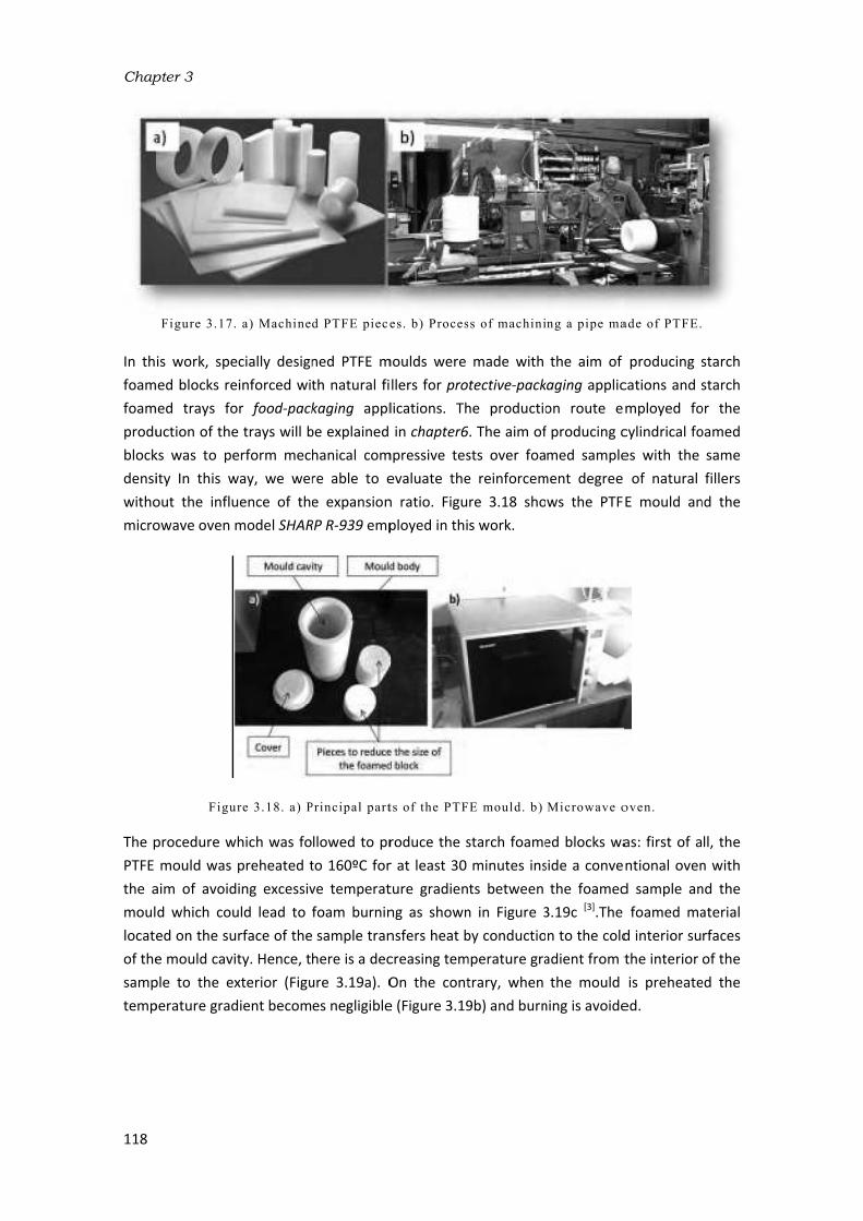
Chap
118
In th
foam
foam
produ
block
densi
witho
micro
The pPTFE the a
moul
locate
of the
samp
temp
pter 3
Figure 3.17
is work, spe
med blocks re
med trays fo
uction of the
ks was to pe
ity In this w
out the influ
owave oven
Figu
procedure wmould was
aim of avoid
d which cou
ed on the su
e mould cav
ple to the e
perature grad
. a) Machine
ecially design
einforced wit
or food‐packe trays will berform mec
way, we wer
uence of th
model SHAR
ure 3.18. a) P
which was fopreheated t
ding excessiv
uld lead to urface of the
ity. Hence, txterior (Figu
dient becom
d PTFE piece
ned PTFE m
th natural fikaging appl
be explained
hanical com
re able to e
e expansion
RP R‐939 emp
Principal part
llowed to pr
to 160ºC for
ve temperat
foam burnin
sample tran
here is a dec
ure 3.19a). O
es negligible
es. b) Proces
moulds were llers for prolications. Th
in chapter6mpressive tes
evaluate the
n ratio. Figu
ployed in thi
ts of the PTF
roduce the sr at least 30 ture gradien
ng as shown
nsfers heat bcreasing tem
On the cont
e (Figure 3.19
ss of machini
made with tective‐pack
he productio
6. The aim of
sts over foa
e reinforcem
re 3.18 sho
s work.
E mould. b)
starch foame
minutes ins
ts between n in Figure 3
by conductio
mperature gra
trary, when 9b) and burn
ng a pipe ma
the aim of kaging applic
on route e
f producing cmed sample
ment degree ws the PTF
Microwave o
ed blocks wa
side a conve
the foamed
3.19c [3].The n to the cold
adient from tthe mould
ning is avoide
ade of PTFE.
producing s
cations and smployed fo
cylindrical foes with the of natural E mould an
oven.
as: first of antional oven
d sample an
foamed ma
d interior su
the interior is preheate
ed.
starch starch
or the oamed
same fillers
nd the
ll, the n with nd the aterial rfaces of the
ed the

Fig
hea
Durin
moul
from were
moul
decre
from image
Once
then out q
heati
In thi
work
cease
3.21 foam
bette
gure 3.19. Te
ted and b) th
ng preliminar
d after being
SATIR). This
evaluated td was pract
eased substa
the momen
e was taken;
Figur
e the mould wrapidly clos
quickly enou
ng temperat
is precise mload (in this
ed, the mou
shows a so
med block on
er.
Mat
emperature d
he mould was
ry tests perf
g preheated
s evaluation to check the tically equal antially to va
nt in which th; hence, heat
e 3.20.Tempe
was preheat
ed and place
ugh to preve
tures of the m
oment micr
s case the s
ld was remo
olid precurso
n the right h
terials, Prod
istribution of
s pre-heated.
was
ormed in ou
was evaluat
can be obse
temperatur
to that set
alues even bhe mould wa
t was lost es
erature distri
ted, a solid ped into the ent the sam
mould.
owave radia
solid precurs
oved from t
or prior to f
ad its surfac
duction Proc
f the foamed
c) Burning o
not preheate
ur laboratory
ted by mean
erved in Fig
re distributio
in the oven
below 130ºC
as taken out
pecially from
ibution of the
precursor wa
microwave mple from be
ation, with asor) for 50
the oven and
foaming and
ces polished
cesses and C
sample whe
of the foam i
ed [ 3 ] .
y the temper
ns of an infra
ure 3.20. Se
on. The temp
n (160ºC) w
. This is bec
t of the oven
m the exterio
e mould after
as placed int
oven chamb
eing partially
a power of 9seconds. On
d the foame
d a foamed so as to ap
Characteriza
n: a) the mou
n the middle
rature distrib
ared camera
everal points
perature in thile the tem
ause severa
n to the mom
or part of the
r being pre-h
o the mould
ber. This step
y dried due
900 watts, wnce the mic
ed sample d
block after ppreciate its
zation Techn
uld was not p
when the mo
bution of the
a (model Hots along the mthe interior o
mperature o
l seconds el
ment in whic
e mould.
heated.
d cavity whic
p must be c to the high
was applied tcrowave rad
emoulded. F
the process
cellular stru
niques
119
pre-
ould
e PTFE tfind‐L mould of the utside apsed ch the
ch was arried h pre‐
to the diation Figure s. The ucture

Chap
120
Figu
Durin
becom
polym
indivi
and i
2mm
repre
Fi
One temp
place
Howe
not ptemp
the sc
al [7], very samp
In thi
filled moul
pter 3
ure 3.21. a) S
ng the applic
mes soft. O
mer matrix idual cells. Ait is accumu
in diamet
esentation of
igure 3.22. S
of the most perature of te metallic th
ever, the use
possible. The
perature of thcreen in itse
the IR meas
accurate in
ple could be q
s work, infra
with the fo
d are show
Solid precurs
fo
cation of mic
Once the vol
is able to An important
lated in the
ter were d
f the process
Scheme of the
foamin
challenging
he sample dhermocouple
e of these me use of Infr
he sample thelf absorbs he
surement w quantitativ
qualitatively
ared images oamed samp
n in Figure
sor before th
aming. c) Fo
crowave rad
atilization te
expand due
t part of the mould cavi
rilled in th
s in which th
e microwave
ng. b) When
aspects of during the pr
es on the m
metallic sens
ared (IR) ca
hrough the seat thus dist
as performe
ve terms bu
y appreciated
of the empty
ple and the 3.23. It is p
e foaming pr
oamed block
diation the semperature
e to the sud
steam gene
ty. In order he mould c
e holes drille
foaming pro
the foam fill
a microwave
rocess. In a mould or eve
sors as well meras could
screen door otorting the med after ope
ut some tem
d.
y mould cav
foamed blo
possible to
rocess. b) Fo
after polishin
olid precurs
of water is
dden genera
rated diffuse
to evacuate
cover. Figur
ed to evacua
cess of starc
ls the mould
e foaming pconventiona
en in contac
as fibre opt
d be an opti
of the micro
measurement
ning the ove
mperature d
ity before thock shortly a
see how th
amed blocks
ng.
or is gradua
s reached (1
ation of ste
es outside the this steam
re 3.22 sho
ate steam are
h foamed blo
cavity.
rocess is ho
al heating pr
ct with the ics inside mi
on but in‐sit
wave oven ist [6]. In the wen door. The
ifferences a
e foaming pfter being r
e temperatu
after microw
ally heated u100ºC) the s
eam which he polymer m
m, several ho
ows a sche
e also observ
ocks. a) Befo
ow to monito
rocess it is ea
molten ma
icrowave ov
tu monitorin
s difficult be
work of Boisce results wer
along the fo
process, the mreleased from
ure of the m
wave
until it soften forms
matrix oles of ematic ved.
ore
or the asy to terial.
vens is ng the ecause hot et re not
oamed
mould m the mould

decre
moul
absor
distri
Figu
Speci
reinfo
to ev
3.2.3
Amon
expan
empl
extru
chem
polym
press
proce
Neve
proce
to pr
Focus
task bno mobtai
result
In an
devel
main
3.24)
polym
eases after t
d (Figure 3.
rbs heat from
bution along
re 3.23. a) M
ific details oorced with naluate the d
3‐ Improved c
ng the foam
nsion ratios oyed in ind
usion foamin
mical blowing
mer/blowing
ses and on tesses based
ertheless, cro
ess, to obtain
event the fosing on the obecause it de
mechanical limning of defi
ting in mate
n effort to loped an al
ly based on . These mou
mer and once
Mat
the foaming
.23a) becaus
m the foame
g the foamed
Mould after b
blo
f this proces
natural fillers
egree of rein
compression
ing processe
and fine cel
ustry (sectio
ng and batcg agents w
g agent syste
he other ha
on compres
osslinking th
n high expan
oamed polym
one‐stage prepends on tmitation for ined shapes
rial loss.
overcome lternative p
the use of sulds allow he
e pressure is
terials, Prod
g process (Fi
se it does n
ed sample. Ind sample is v
eing pre-heat
ock after bein
ss will be fou
s with a cylin
nforcement o
n moulding
es in which alular structu
on 2.6.1.2). ch foaming
hich allows
em by equip
nd, high‐thic
sion mouldin
he polymer nsion ratios dmer leaking orocess, the che chemical the polymer
such as blo
these draw
rocess calle
pecifically de
eat and pres
s released, th
duction Proc
igure 3.23b)
not interact n addition, itvery homoge
ted. b) Moul
ng released f
und in chaptndrical shap
of these fibr
applying pre
ures, compre
Its main pe
processes bon the on
pment which
ckness foam
ng: the one‐matrix is re
during the se
out of the mcontrol of the
composition
r to expand ocks and bo
wbacks, the d improved
esigned mou
ssure to be the mould ca
cesses and C
) with respe
with the m
t has been oeneous as sho
d with the fo
from the mou
ter 4in which
e were prod
es.
essure is key
ession mould
culiarity, wi
based on gae hand, pre
h is not exce
ed blocks to‐stage procesequired in b
econd stage mould when
e density by n and the pr
once the pre
oards require
Cellular Ma
d compressio
ulds called setransmitted vity is able t
Characteriza
ect to that o
microwave ra
bserved that
own in Figur
oamed block i
uld.
h starch‐base
duced by mic
to obtaining
ding is one oth respect t
as dissolutioessure to b
essively soph
o be produce
ss and the twboth cases. and in the oproducing lothis process
ocessing par
essure is rele
es an additi
aterials Laboon moulding
elf‐expandabsimultaneou
o change its
zation Techn
of the pre‐hadiation and
t the temper
res 3.23b and
inside. c) Fo
ed foamed bcrowave rad
g foams with
of the most wto others su
on, is the u
e applied t
histicated su
ed. There ar
wo‐stage prIn the two‐one‐stage prow‐density fs is a very di
rameters. Th
eased. Henc
ional cutting
oratory (Cel
g (ICM) wh
ble moulds (Fusly to the m volume to l
niques
121
heated d only rature d c.
amed
blocks diation
h high widely uch as use of o the
uch as re two ocess. ‐stage ocess, oams. fficult
here is e, the
g step
llMat) hich is Figure
molten et the

Chap
122
polym
amou
and press
conte
the c
stabil
moul
to ob
The mdurin
mate
foam
are in
Prior blowi
pter 3
mer expand.
unt of blowin
with varied
sure, temper
ent. In additi
case of low lization of t
d is hermeti
btain foams o
main steps ong the proce
erial inside a
ming step wit
ncluded.
Figur
to the foam
ing agent by
. Moreover, ng agent add
d cellular st
rature/time aon, the mou
viscosity no
he cellular s
cally sealed of a defined s
of the ICM ro
ess is repres
re also pres
th the chang
re 3.24. Stag
ming stage it y melt‐blend
they are ab
ded. In this wructures by
and the chem
ulds are able on‐crosslinke
structure ca
to prevent tshape: disks,
oute are show
sented versu
sented in ord
ges produced
es of the imp
is necessary
ing (section
ble to contr
way, it is pos
y simply mo
mical compo
to keep the ed polymers n be perfor
the entrance
, cylinders, p
wn in Figure
us time. Mo
der to bette
d in the mou
proved comp
y to produce
3.2.1.2) The
rol the expa
ssible to obta
odifying pro
osition, like ffoamable sy
which cont
rmed by coo
e of liquids. Lprisms etc.
e 3.24 in whi
oreover, sche
er understan
uld. In these
ression moul
e a homogen
first temper
nsion ratio ain foams of
ocessing par
or instance tystem inside ains a gas d
oling with w
Last but not l
ch the temp
emes of the
nd the relati
e schemes al
ding route (I
neous blend rature cycle
regardless o
f the same drameters su
the blowing the cavity ev
dissolved an
water becaus
least, it is po
perature evo
e mould wit
on between
ll the mould
ICM).
polymer‐cheshown in th
of the ensity ch as agent ven in
nd the se the ossible
lution th the n each parts
emical e plot

of Fig
melti
blow
The i
Then
body betw
and t
usual
bars. gas pin the
nucle
press
pisto
Fig
The m
dime
pisto
moul
rings moul
(ER) oof th
moul
An in
press
expan
gure 3.25 rep
ng temperat
ing agent (Tm
nitial mould
, it is closed
and the up
ween the hot
temperature
lly in the ran
Temperatur
produced is de formation
ei appear an
sure inside thn of the mou
gure 3.25.a) A
main featur
nsions, conc
n is free allo
d is called se(Figure 3.24
d. The pisto
of the final fe process a
d containing
nteresting ch
sure exerted
nsion proces
Mat
presents the
ture (Tm) of t
m<T<Td).
d cavity can d by screws pper and bo
‐plates of an
e are applied
nge of 190‐2re rises up tdissolved int
of the mol
nd gas diffu
he cells beco
uld up to the
Automatic hy
e of this fo
cretely its he
owing the mo
elf‐expandab4) with diffe
n is displace
oam is there
nd the heig
g the foam in
haracteristic d by the we
ss and hence
terials, Prod
compoundi
the polymer
be filled wit
and sealed bttom parts
n automatic d simultaneo
200ºC while tto the decom
to the polym
ten polymer
uses from th
omes high en
e maximum h
ydraulic pres
aming proce
eight, during olten polyme
ble mould. Terent heights
d up to the efore, the rat
ght of the m
nside is coole
of this proc
eight of the
e, the cellula
duction Proc
ng process iand below t
th expandab
by rubber joof the mou
hydraulic pr
ously (1). Th
the pressure
mposition temer due to th
r/gas system
he molten p
nough to exp
height allowe
ss. b) Cylindr
ess is the a
the expansi
er to expand
his is possib
s placed bet
height estab
tio between
mould cavity ed down and
cess is that
stainless‐st
ar structures
cesses and C
n which tem
the decompo
ble pellets o
oints which ald. At this m
ress as show
he temperat
es employed
emperature o
he high pres
m. Once the polymer to pand the mo
ed by the mo
rical mould b
ability of the
ion of the po
d in one spe
le because otween the m
blished by ththe height oat the begi
d stabilized b
the molten
eel piston.
obtained is
Characteriza
mperature ris
osition tempe
r with therm
are placed bmoment, the
wn in Figure 3ures used in
d varied betw
of the blowi
sures applie
pressure is the cells cr
olten polyme
ould cavity.
between the h
e mould cav
olymer. The cific directio
of the emplo
main body an
e ring. The rof the mould
inning (ER=h
y water.
polymer ex
How this fa
a matter wh
zation Techn
ses only abov
erature (Td)
moformed sh
between the
e mould is p
3.25 and pre
n this proces
ween 5 bars ing agent an
ed (2) which released (3
reated. Then
er and to pus
hot-plates pre
vity to chan
movement on. This is wh
oyment of mnd the top o
relative expa
d cavity at thhf/h0). Finally
xpands unde
act influence
hich has not
niques
123
ve the of the
heets. e main placed essure ss are to 80
nd the result
3), cell n, the sh the
ess.
ge its of the hy the etallic of the ansion he end y, the
er the es the t been
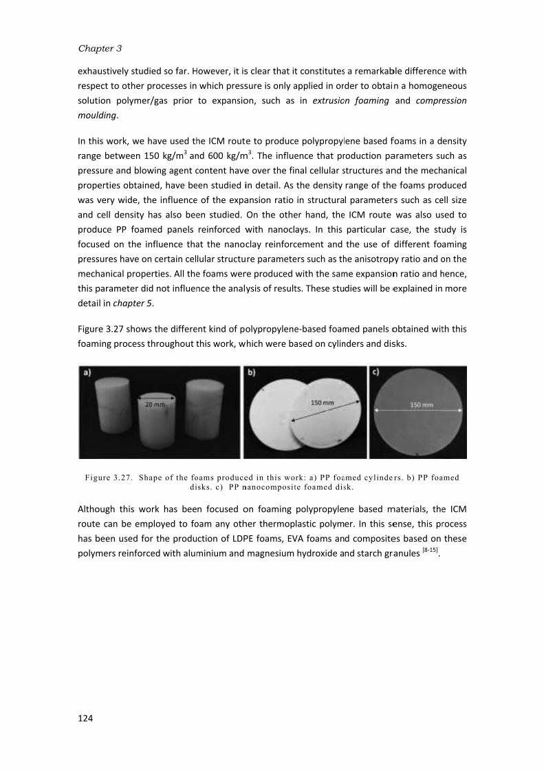
Chap
124
exhau
respe
solut
moul
In thi
range
press
prope
was vand c
produ
focus
press
mech
this pdetai
Figur
foam
Figu
Altho
route
has bpolym
pter 3
ustively stud
ect to other ion polymer
lding.
is work, we e between 1sure and blow
erties obtain
very wide, thcell density uce PP foam
sed on the i
sures have ohanical prope
parameter di
l in chapter 5
e 3.27 show
ming process t
ure 3.27. Sh
ough this wo
e can be em
been used fomers reinforc
died so far. Hprocesses inr/gas prior
have used th150 kg/m3 an
wing agent cned, have be
he influence
has also bee
med panels nfluence tha
n certain cel
erties. All the
id not influen
5.
ws the differe
throughout t
hape of the fo
di
ork has bee
ployed to foor the produ
ced with alum
However, it is which press
to expansio
he ICM route
nd 600 kg/m
content have
een studied ie of the expa
en studied. reinforced w
at the nanoc
lular structu
e foams wer
nce the analy
ent kind of po
this work, w
oams produce
sks. c) PP n
n focused o
oam any oth
ction of LDP
minium and
s clear that itsure is only aon, such as
e to produce
m3. The influe
e over the fiin detail. As
ansion ratio On the othe
with nanocl
clay reinforc
re paramete
re produced ysis of result
olypropylene
hich were ba
ed in this wo
nanocomposit
on foaming her thermop
PE foams, EV
magnesium
t constitutes
applied in or
in extrusio
e polypropyl
ence that pr
nal cellular sthe density in structura
er hand, the
ays. In this cement and ers such as thwith the sam
ts. These stu
e‐based foam
ased on cylin
rk: a) PP foa
te foamed dis
polypropyle
lastic polym
VA foams an
hydroxide a
s a remarkab
der to obtai
on foaming
lene based froduction pa
structures an
range of the
l parameter
e ICM route particular c
the use of he anisotrop
me expansion
dies will be e
med panels onders and dis
amed cylinde
sk.
ne based m
er. In this se
d composite
nd starch gra
ble difference
n a homoge
and compre
foams in a darameters su
nd the mech
e foams prod
rs such as ce
was also us
case, the stu
different foa
py ratio and on ratio and hexplained in
obtained wit
sks.
rs. b) PP foa
materials, the
ense, this pr
es based on anules [8‐15].
e with neous ession
ensity uch as anical duced
ell size sed to udy is aming on the hence,
more
th this
amed
e ICM rocess these

Materials, Production Processes and Characterization Techniques
125
3.3‐ Characterization techniques8,9,10,11,12,13,14,15]
The characterization techniques employed in this work are listed in Table 3.8. A more detailed explanation of how the samples which were produced were characterized by these techniques will be found in the chapters containing the experimental results. These techniques were mainly focused on studying the relationship between the cellular structure and the mechanical properties.
Characterization techniques. Chapters
Mechanical tests to low strain rates. Universal machine INSTRON model 5500R625.
Compressive tests. (ISO 604‐2002) 4,5 Tensile tests( ISO 527). 4,5 Bending tests. (ISO 178). 5
Starch morphology and cellular structure characterization by scanning electron microscopy (SEM) Electronic Microscope JEOL JSM‐820.
4,5
Natural fibres morphology by optical microscopy.
Optic microscope LEICA mo Del DM2500M. 4
Density measurement by the volumetric method.(ASTM D1622‐08).
Weighing scale METTLER Toledo AT261. 4,5
Open cell content measurement. Gas pycnometer model AccuPyc II 1340 Micromeritics. (ASTM D6226‐10).
4,5
Evaluation of the thermal properties of the polymers and blowing agent content by thermogravimetric analyses (TGA) TGA/SDTA Mettler 851e
4,5
Table 3.8.Characterization techniques.

Chapter 3
126
References
[1] Liu, X. and Wu, Q. PP/clay nanocomposites prepared by grafting/melt intercalation. Polymer. 42,
10013‐10019. 2001. [2] Bogdat, D. and Prociak, A. Microwave‐enhanced polymer chemistry and technology. Blackwell
Publishing. 2007. [3] Zhou, J.; Song, J. and Parker, R. Microwave‐assisted moulding using expandable extruded pellets
from wheat flours and starch. Carbohydrate Polymers. 69, 445‐454. 2007. [4] Meredith, R. Engineers handbook of industrial microwave heating. The institution of electrical
engineers. London. 1998. [5] Shogren, R.L.; Lawton J.W. and Tiefenbacher, K.F. Baked starch foams: starch modifications and
additives improve process parameters, structure and properties. Industrial Crops and Products. 16, 69‐79. 2002.
[6] Tong, C.H.; Sheen, S.A.; Fu, Y.H.; Goedken, D.L. and Lund, D.B. Microwave heat transfer in food. 149‐163. in: Advances in Food Engineering. Singh, P. and Wirakartakusumah, M.A. CRC Press: Boca Raton, FL.1992.
[7] Boischot, C.; Moraru, C.I.; and Kokini, J.L. Factors that influence the microwave expansion of glassy amylopectin extrudates. Cereal Chemistry.80, 56‐61. 2002.
[8] Rodríguez‐Pérez, M.A.; Lobos, J.; Pérez‐Muñoz, C.A.; de Saja, J.A.; González, L.M. and del Carpio, M.A. Mechanical behaviour at low strains of LDPE foams with cell sizes in the microcellular range: advantages of using these materials in structural elements. Cellular Polymers. 27, 347‐362. 2008.
[9] Rodríguez‐Pérez, M.A.; Lobos, J.; Pérez‐Muñoz, C.A. and de Saja. J.A. Mechanical response of polyolefin foams with high densities and cell sizes in the microcellular range. Journal of Cellular Plastics. 45, 389‐403. 2009.
[10] Román‐Lorza, S. Formulación y caracterización de materiales celulares retardantes de llama libres de halógenos basados en poliolefinas. Tesis Doctoral. Universidad de Valladolid. España. 2010.
[11] Román‐Lorza, S.; Rodríguez‐Pérez, M.A. and de Saja, J.A. Cellular Structure of halogen‐free flame retardant foams based on LDPE. Cellular Polymers. 28, 249‐268. 2009.
[12] Román‐Lorza, S.; Rodríguez‐Pérez, M.A.; de Saja, J.A. and Zurro, J. Cellular structure of EVA/ATH halogen‐free flame retardant foams. Journal of Cellular Plastics. 10, 1‐21. 2010.
[13] Román‐Lorza, S.; Sabadell, J.; García‐Ruiz, J.J.; Rodríguez‐Pérez, M.A. and de Saja, J.A. Fabrication and characterization of halogen free flame retardant polyolefin foams. Materials Science Forum. 636/637, 98‐205. 2010.
[14] Rodríguez‐Pérez, M.A.; Simões, R.D.; Constantino, C.J.L. and de Saja, J.A. Structure and physical properties of EVA/Starch precursor materials for foaming applications. Journal of Applied Polymer Science. 212, 2324‐2330. 2011.
[15] Rodríguez‐Pérez, M.A.; Simões, R.D.; Román‐Lorza, S.; Álvarez‐Laínez, M.; Montoya‐Mesa, C.; Constantino, C.J.L. and de Saja, J.A. Foaming of EVA/Starch blends: Characterization of the structure, physical properties and biodegradability. Polymer Engineering and Science. 52, 62‐70. 2012.

CHAPTER 4:
DEVELOPMENT OF STARCH-BASED MATERIALS


Contents
4.1- Introduction. ...................................................................................................................... 131
4.2- Solid starch-based biocomposites. ................................................................................... 133
4.3- Foamed starch-based biocomposites ............................................................................... 141
4.4- Summary and Conclusions ................................................................................................ 154

Chapter 4
130

4.1- I
Starc
packa
with
finally
starc
starch
ment
can b
mate
the o
cond
when
obtai
restri
etc.)
very i
Unfo
produ
impo
with
prope
On t
prope
frequ
ntroduction
h possesses
aging applica
common sy
y, it is biode
h granules, w
h (TPS) drast
tioned in cha
be processed
erial is adequ
objective of
ucted. On th
n it has bee
ned is usual
icts its appli
require a ce
interesting m
rtunately, th
uction of fo
rtant drawb
water. In th
erties as sho
Figure 4.1.
he one han
erties becau
uently rubbe
n
numerous a
ations: it is w
nthetic poly
erived and b
which are ex
tically broad
apter 2. Afte
d by conven
uate for use
f the ACTIB
he other han
n previously
ly dry and br
cation for fo
ertain degre
materials for
hese materi
ood-packagi
backs are rel
his thesis, res
own in the sc
Drawbacks o
nd, the plas
se during th
ery at ambi
advantages t
widely availa
mers emplo
biodegradab
xtracted from
dened the ap
er plasticizat
ntional equip
in the produ
IOPACK pro
d, thermopla
y plasticized
rittle becaus
ood-packagin
e of flexibili
protective-p
als also pre
ng trays an
ated to thei
search has b
heme of Figu
of starch and
sticization p
is process st
ent temper
that make it
ble and rene
oyed in this m
ble. Howeve
m plants is di
pplication of
tion, starch t
pment empl
uction of biod
oject in whic
astic starch c
with water
se water is lo
ng applicatio
ty. On the c
packaging ap
esent severa
nd protectiv
ir poor mech
been focused
ure 4.1.
d strategies u
process invo
tarch becom
rature. The
Developme
t a very pro
ewable, its p
market such
er, the proc
ifficult. The d
starch in th
turns into a
oyed in the
degradable f
ch the main
can be empl
. However, t
ost during th
ons because
contrary, the
pplications.
al drawback
ve-packaging
hanical prop
d on the imp
used to overc
olves a dras
mes a mostly
reinforceme
nt of starch
mising polym
rice is very l
as PP, PET,
essing and t
developmen
e plastic ma
thermoplast
plastic indu
food-packag
n part of t
oyed for foa
the foamed
e expansion
e these prod
ese kinds of
s that make
g foams dif
perties and t
provement o
come them in
stic reductio
amorphous
ent with lig
h-based mat
mer especia
ow in compa
XPS and EP
transformati
t of thermop
arket as prev
tic polymer
ustry. This fl
ing trays, wh
his research
aming applica
product wh
process. Th
ducts (trays,
starch foam
e its use fo
fficult. The
their great a
of the mech
n this thesis
on of mech
material wh
nocellulose-
terials
131
lly for
arison
PS and
ion of
plastic
viously
which
exible
hich is
h was
ations
hich is
is fact
films,
ms are
or the
most
ffinity
anical
anical
hich is
based

Chapter 4
132
natural fibres represents an interesting strategy to overcome this problem because they are
widely available (their main source being from agricultural and forest plants) and their
chemical compatibility with starch is very high. There are lot of pieces of work in literature
reporting the production of starch-based biocomposites with very promising results. These
works were described in section 2.4.2.2. One of the works included in this chapter (section4.2)
describes the production of biocomposites based on thermoplastic starch reinforced with
barley straw and grape fillers. The main objective is to improve the mechanical properties of
TPS and obtaining a bioderived and biodegradable material able to be used for the production
of flexible food-packaging trays.
The use of starch foams for protective packaging applications has been limited due to their
poor cellular structures and mechanical properties mainly derived from the production process
employed (generally extrusion foaming and baking).The production of starch-based foams
with higher mechanical performances from more efficient foaming routes is one of the aims of
this thesis. In this sense, a microwave foaming process was employed due to the low energy
consumption and to the heating transfer, which is more homogeneous (volumetric heating).
Moreover, natural fibres were employed in order to increase the strength of the foams and to
study their effect in the foaming mechanisms of this process in which the use of natural fibres
have not been reported so far. The research conducted on this topic is presented in section
4.3.

Development of starch-based materials
133
4.2- Solid starch-based biocomposites
The production of biocomposites based on TPS reinforced with natural fibres brought about
the elaboration of a scientific article. This article was published in a scientific journal called:
“Polímeros: Ciência e Tecnologia”, which is included in this section and whose title is:
Strategies to improve the mechanical properties of starch-based materials: plasticization and
natural fibre reinforcement.
In spite of the fact that the materials developed in this section are solid, some of the results
obtained can be extrapolated to what would happen with foamed materials. For instance the
reinforcement of TPS with natural fibres was carried out not only on solid materials but also on
foamed materials produced by microwave foaming. The comparison between both systems
will be one of the issues discussed at the end of this chapter (section 4.4)
The methodology employed to evaluate the degree of the reinforcement of natural fibres in
the solid TPS was: firstly, studying the adhesion and dispersion degree along the polymer
matrix by means of SEM micrographs and secondly, studying the mechanical properties of the
materials produced by tensile tests. The influence of the plasticizer content was also evaluated
prior to the biocomposites production. Thus, TPS with different amounts of glycerol were
produced and mechanically characterized.
Barley straw and grape fibres were selected because they represent an important source of
lignocellulose wastes from the agricultural industry in Spain. Moreover, their morphology is
very different which allowed the influence of fibre morphology on the mechanical properties
of TPS to be studied. The results obtained will be analysed by the comparison with analytical
models found in literature that describes the mechanical response of composites: the law of
mixtures, the Halpin & Tsay model and the Kerner & Nielsen model. They were chosen for this
study because they described the reinforcement degree of particles of different geometry
(spherical particles and long fibres) and different orientations along the matrix.
Finally, a comparison between the properties of the materials developed in this article and
those of synthetic polymers employed in the market of food-packaging trays is shown. In this
comparison a biodegradable polymer such as PLA is also included.

Chap
134
pter 4

Development of starchh-based matterials
135

Chap
136
pter 4

Development of starchh-based matterials
137

Chap
138
pter 4

Development of starchh-based matterials
139

Chap
140
pter 4

4.3- F
In pri
starc
trays
sectio
(Figur
The a
reinfo
foam
and i
reinfo
litera
articl
the la
to im
on us
defin
foam
betw
more
Morp
obtai
obtai
and
challe
cellul
One o
betw
is gen
most
Ashby
the p
break
struct
the m
Foamed star
inciple, the m
h-based tray
found in th
on 4.1, whic
re 4.2b) with
Figure
article includ
orced with
ming. This art
its title is: C
orced with n
ature (section
e but from
ack of adhes
mprove the p
sing thermo
ed shape.Af
ms (section 2.5
ween their ce
e insight into
phological pa
ned by ima
ned under c
the energy
enging, takin
lar structure
of the most
ween the mec
nerally assum
of the analy
y (equation2
production o
ks this comm
ture stabiliza
material befo
rch-based bio
microwave f
ys with the
he market (F
ch make th
h the aim of
e 4.2. XPS foo
ded in this s
natural fibr
ticle was pub
Cellular Struc
natural fibre
n 2.5.1.3) pr
pellets, whic
sion between
properties of
oformed she
fter revising
5), it is evide
ellular structu
o these relat
arameters of
ge analyses
compression
y absorbed.
ng into acco
but also the
interesting a
chanical prop
med that foa
ytical model
2.1). This gen
of starch foa
mon assumpt
ation in thes
ore and after
ocomposites
foaming proc
aim of repla
Figure 4.2a).
is process m
replacing EP
od-packaging
section desc
res for prot
blished in an
cture and m
s and produ
roduced star
ch resulted i
n the expand
the foams.
ets for the
the existing
ent that ther
ures and the
tionships by
f the cellular
of SEM mic
n tests, such
The aim o
ount the role
e properties o
and innovativ
perties of the
am propertie
ls found in li
neral behavio
ms in which
tion. This art
se foamed sy
r foaming by
s
cess seemed
acing comm
However, t
more suitab
PS foams (exp
g tray and EP
cribed an ap
tective-packa
n internation
mechanical p
uced by micr
rch foams in
in foams wit
ded pellets.
In this work
production
g literature r
re are few st
eir mechanic
y characteriz
r structure, s
crographs a
h as the com
of establish
e that natur
of the solid m
ve aspects o
e solid precu
es exponenti
iterature, su
our is graphi
h water acts
ticle aims to
ystems (sect
using the Gi
Developme
d to be an in
on XPS (ext
there are so
ble for prote
panded poly
S box for pro
proach to p
aging applic
nal journal: I
properties of
rowave heat
n a similar w
th poor mec
Moreover, t
k an interesti
of continuou
related to th
udies establi
al properties
zing the cellu
such as cell s
nd related t
mpressive m
hing these
ral fibres pl
matrix within
of this article
ursors and th
ially decreas
uch as the cu
ically illustra
as the plast
explain wha
tion 2.4) and
ibson & Ashb
nt of starch
nteresting str
ruded expan
me limitatio
ective-packa
styrene).
otective-pack
roduce starc
cations base
Industrial Cro
f starch-base
ting. Previou
way to those
chanical perf
hey did not
ing strategy
us starch fo
he productio
ishing consis
s . This articl
ular structur
size and anis
to the mech
odulus, com
relationship
ay in modify
n the cell wa
is the comp
hose of the fo
e with densi
ubic cell mod
ted in Figure
ticizer and t
at happens d
the mechan
by model.
h-based mat
rategy to pro
nded polysty
ons, mention
aging applica
kaging .
ch foamed b
ed on micro
ops and Pro
ed foamed b
us works fou
e obtained i
formances d
use natural
is followed
amed block
on of starch-
stent relation
le aims to pr
re in more d
sotropy ratio
hanical prop
mpressive str
ps was espe
fying not on
alls and strut
parison perfo
oams produc
ity as describ
del of Gibso
e 2.14. . How
the blowing
during the ce
nical propert
terials
141
oduce
yrene)
ned in
ations
blocks
owave
ducts,
blocks
und in
n this
due to
fibres
based
s of a
based
nships
rovide
detail.
o were
perties
rength
ecially
ly the
s.
ormed
ced. It
bed in
on and
wever,
agent
ellular
ties of

Chap
142
pter 4

Development of starchh-based matterials
143

Chap
144
pter 4

Development of starchh-based matterials
145

Chap
146
pter 4

Development of starchh-based matterials
147

Chap
148
pter 4

Development of starchh-based matterials
149

Chap
150
pter 4

Development of starchh-based matterials
151

Chap
152
pter 4

Development of starchh-based matterials
153

Chapter 4
154
4.4- Summary and Conclusions
First of all, several biobased and biodegradable formulations were produced based on
thermoplastic starch, which could be applied for the production of solid flexible materials for
food-packaging applications and for the production of rigid foamed materials for protective-
packaging applications. Their production required the optimization of lab-scale production
processes such as extrusion, thermoforming and microwave foaming.
The processing parameters were carefully selected and varied depending on the formulation
and the final application. In this sense, the most important modifications of parameters
derived from the kind of plasticizer used: glycerol or water. The use of water required softer
conditions (temperatures and pressures) than those employed with glycerol in order to avoid
losing it prior to foaming (water acts as the blowing agent).
From a structural point of view, the most important variations were found after adding natural
fillers. The solid composites obtained showed, in general, a good dispersion of fibres along the
polymer matrix, suggesting that processing conditions were chosen properly. The adhesion
degree varied depending on the fibre employed which could be due to their different chemical
composition. Interphases between grape fillers and the polymer matrix were detected
whereas barley straw fibres presented very good adhesions. On the contrary, a proper
adhesion degree between all the fibres and the polymer matrix was achieved in the foamed
materials.
These morphological differences are also reflected on the mechanical properties obtained.
Only the addition of barley straw fibres produced a clear improvement in the stiffness and
strength of solid TPS while the foamed materials did not show this behaviour. In this case,
grape fillers produced the better results not only in the compressive modulus but also in the
compressive strength. These differences found for both kinds of materials (solids and foams)
could be attributed to different factors:
The mechanical tests performed were different: tensile tests for solids and
compressive tests for foams.
The plasticizer used was different: glycerol for solids and water for foams, which varied
the chemistry of the polymer matrix and the processing parameters employed.
The foaming process induced changes in the polymer matrix properties (loss of
plasticizer) that could promote variations in the adhesion degree between the polymer
and the fibres during expansion.
The cellular structure of the foams was clearly influenced by the presence of fibres.
The addition of barley straw fibres and cardoon fibres, which present smaller sizes
than those of grape fibres, reduced the cell size of the foams produced likely due to a
heterogeneous nucleation of cells during the first stages of foaming.
In any case, it is clear that the addition of fibres represented an interesting and successful
strategy to improve the mechanical properties of both systems, the solid and foamed materials

Development of starch-based materials
155
based on TPS. In the particular case of the foamed systems, the compressive properties of the
developed foams were clearly higher than those previously published by other authors.
The employment of analytical models frequently used in literature to describe the mechanical
properties of solid composites and foamed materials proved to be an interesting tool to
evaluate certain aspects of both kinds of materials. In the case of the solid biocomposites, the
Halpin & Tsai model fitted very well with the experimental results obtained with the
composite reinforced with barley straw fibres. On the other hand, the Gibson & Ashby model
allowed the prediction of the properties of the solid cell walls and struts of the starch-based
foams produced by microwave radiation. This is important because the properties of the
polymer matrix changes gradually during foaming. Water goes from the polymer matrix to the
cells making the polymer matrix less plasticized at the end of the process.
Finally, the formulations and materials produced permitted the development of lab-scale
production routes for food-packaging trays and protective-packaging foams. In the first case,
the production route is very similar to that employed in industry for the production of solid
flexible trays based on PET and PP because it consists of two stages: extrusion and
thermoforming. This means that the solid formulations employed could be scaled-up for the
production of food-packaging trays. In the second case, the production route was adapted for
the production of foamed food-packaging trays. However, it is also suitable for the production
of protective packaging foams of a defined shape such as those employed for packing
household appliances. These production routes will be explained in more detail in chapter 6.


CHAPTER 5:
DEVELOPMENT OF POLYPROPYLENE FOAMS


Contents
5.1- Introduction .......................................................................................................................... 161
5.2- Production of medium-high density PP-based foams. ........................................................ 163
5.3- Production of low-density PP-based foams ........................................................................ 166
5.4- Conclusions ........................................................................................................................... 201

Chapter 5
160

5.1-
Poly
main
as P
prod
stiff
foam
of th
Figu
First
emp
of co
hom
evol
repr
At th
high
prod
foam
proc
Hen
stru
the
allow
rate
up o
Introductio
ypropylene (
n alternative
PVC, PET, P
duction) and
ness and st
ming applicat
he scheme sh
ure 5.1.Drawb
t of all, the
ployed in str
onventional
mogeneous c
lution of the
resent this ev
he beginning
h expansion
duction proc
ming, gas dis
cess was con
ce, the scal
ctures obtai
gas dissolu
ws microcell
es ≈109 cells/
of the techn
n
PP) represen
e to replace c
PU, SAN, et
d moreover b
rength. Nev
tions that ha
hown in Figu
backs of poly
stiffness and
uctural appl
linear polyp
cellular stru
e project dur
volution.
g of the proj
ratios (branc
cess. In prin
ssolution foa
nsidered bec
ing-up of th
ned are poo
tion process
ular structur
/cm3). Howev
nology would
nted, within
common po
tc. fundame
because of a
ertheless, th
ad to be ove
ure 5.1.
ypropylene fo
d strength o
ications (PVC
propylenes is
ctures very
ring the four
ect the only
ched polypro
nciple, three
aming and co
cause it is ca
he process w
r: large cell s
s represente
res to be obt
ver, obtainin
d have been
the framew
lymers empl
entally beca
all the polyo
his polymer
rcome. Thes
f or foaming aovercome th
of PP are stil
C, PET, PU e
s poor makin
difficult. Th
years it last
clear thing w
opylene) but
e existing te
ompression m
arried out u
would have
sizes and wid
ed one of t
tained due to
ng foams wit
n very expen
Develo
work of the E
loyed in the
use it is a
olefins, it is t
presented s
se drawbacks
applications ahem.
l far from th
etc.) and sec
ng the produ
he path to
ted and the t
was the type
t there were
echnologies
moulding. In
under the ac
been afford
de cell size d
he most int
o the high pr
th a defined
nsive becaus
opment of p
European pr
market of st
low-cost p
the one whic
some drawb
s are highligh
and strategies
hose of the
ondly, the fo
uction of low
solve these
two works in
e of PP to be
a lot of dou
could have
the first pla
ction of temp
dable. Never
distributions.
teresting app
ressures app
shape is diff
e stainless-s
polypropylen
roject NANC
tructural foa
polyolefin (a
ch offers the
backs when
hted in the r
s used in this
polymers co
oaming perf
w-density foa
e drawbacks
ncluded in th
e employed t
ubts about a
e been appl
ace, the free
perature exc
rtheless, the
. In the secon
proaches be
plied (high nu
ficult and the
steel autocla
ne foams
161
CORE, the
ms, such
abundant
e highest
used for
ed boxes
s work to
ommonly
ormance
ams with
set the
his thesis
to obtain
a suitable
ied: free
foaming
clusively.
e cellular
nd place,
ecause it
ucleation
e scaling-
aves with

Chapter 5
162
thick walls are required. In addition, cross-linking of PP would be needed in this type of process.
Finally, compression moulding seemed to be the most adequate foaming route because it
combines the advantages of the previous ones: high pressures and easy scaling-up (the main
equipment needed is hydraulic presses to transmit the pressure and temperature). However,
there was a major drawback: this technology requires cross-linking the polymer matrix because
otherwise, the polymer would leak out from the mould after releasing the pressure.
For these reasons, the Improved Compression Moulding Route (ICM) emerged as the most
promising strategy to produce this kind of foams. Its main peculiarity with respect to the
conventional compression-moulding route is that due to the mould design PP foams can be
produced with a defined shape without cross-linking the polymer matrix (see section 3.2.3 for
more details). However, there was a lack of knowledge about how processing parameters such
as pressure, temperature, blowing agent content and expansion ratio to name a few, influenced
the structures and hence, the mechanical properties of PP foams. The work included in section
5.2 constituted the first step for the generation of knowledge regarding the production of PP
foams by the ICM route. This work was especially focused on the influence that the blowing
agent content and the expansion ratio can induce in the cellular structures, hence, in the
mechanical properties of these materials.
Not only is the production process important for obtaining the suitable foam for a determined
structural application, but also the polymer employed. For this application, in which low-density
rigid foams are required, a polymer combining both, good foaming performance and great
stiffness and strength, is required. These are properties, possessed by the high melt strength
branched polypropylene employed in the work included in section 5.3. In this work, nanoclays
are used with the principal aim of increasing the mechanical properties of the solid cell walls and
struts in the final foam which is produced. Indeed, this work tries to broaden the comprehension
about the particular foamed systems in which a polymer is combined with a nanoparticle.
One of the most interesting aspects of the works developed during this chapter is the great
variety of cellular structures obtained. On the one hand, in the work included in section 5.2,
different cellular structure were obtained in terms of cell size, cell density and open cell content
by modifying the blowing agent content and the expansion ratio (medium-high-density PP
foams). On the other hand, in the work included in section 5.3, anisotropic cellular structures
were obtained by restricting the expansion of the polymer in one single direction (low-density
PP foams). Moreover, the addition of nanoclays represented another source of cellular structure
variation because their addition involved the production of foams with higher cell densities and
with bimodal cell size distributions.
The next two sections present the results obtained in the form of articles which have already
been already published (in the case of the work included in section 5.2) or sent to international
scientific journals (in the case of the work included in section 5.3). The section has been
classified according to the density of the foamed PP panels obtained: medium-high density
foams with a relative density > 0.2 (section 5.2) and low-density foams with a relative density
<0.2 (section 5.3).

Development of polypropylene foams
163
5.2- Production of medium-high density PP-based foams
For the development of PP foams to be employed for structural applications the first step was to
perform a detailed analysis of the relation production-structure-properties and thus, optimizing
formulations and production parameters for this particular polymer matrix. An example of this
relation is given in the work included in this section: Production of non-cross-linked
thermoplastic foams with a controlled density and a wide range of cellular structures, which was
published in an international scientific journal (“Journal of Applied Polymer Science”).
The objectives of this work are firstly, optimizing formulations and production parameters in the
ICM route and secondly, gaining knowledge about how different cellular structures and
expansion ratios affect the mechanical properties of PP foams. In this sense, a linear PP was
employed because its low stability in the molten state makes it very sensitive to different
blowing agent contents (from 1 to 15 wt%) and to the different expansion ratios (1.6, 2 and 3) to
which the molten polymer was subjected. The cellular structures obtained were characterized in
detail with the aim of defining important morphological parameters of these foams such as cell
size, cell density and open cell content and correlating them with the foams mechanical
properties in the compression, tension and bending modes

Chapter
164
r 5

Develoopment of ppolypropylenne foams
165

Chap
166
pter 5

Developmment of polyypropylene ffoams
167
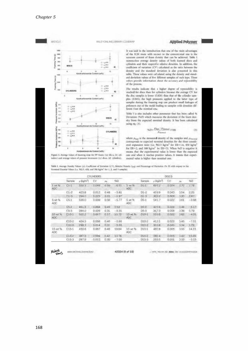
Chap
168
pter 5

Developmment of polyypropylene ffoams
169

Chap
170
pter 5

Developmment of polyypropylene ffoams
171

Chap
172
pter 5

Developmment of polyypropylene ffoams
173

Chapter 5
174
5.3- Production of low-density PP-based foams
The knowledge obtained throughout the work performed in section 5.2 was fundamental to
design the work included in this section (Anisotropic polypropylene foams filled with nanoclays:
microstructure and elastic properties). In this case, PP based foams were produced by the
same route (ICM foaming process) but employing a polymer (branched polypropylene) able to
be expanded to higher expansion ratios than the linear one employed in section 5.3. This is
because of the strain-hardening phenomenon experienced by this specific polymer. For this
reason, lower densities than the ones obtained in section 5.2 were achieved (relative density <
0.2). Some additional foaming parameters not considered in section 5.2 were analysed in this
section. This is the case of the applied pressure during foaming, which is studied in this work
by producing foams at four different pressures (from 0.5 MPa to 81MPa). Moreover, the
addition of nanoclays represented an interesting strategy to improve the mechanical
properties of the virgin polymer and to modify the cellular structure (heterogeneous
nucleation of cells) in such a way that foams with better mechanical performances could be
obtained. This is another important goal of this work: studying the effect that nanoclays have
in these PP-based foams produced at different pressures.
One interesting feature of the low-density foams produced is the formation of anisotropic
cellular structures due to the fact that the expansion is restricted to only one direction. A
detailed characterization of the cellular structures obtained has been performed, focusing
especially on anisotropy, due to the importance of this morphological parameter on the final
mechanical properties obtained. The linear-elastic mechanical properties in compression
(compressive modulus) were correlated with the anisotropic cellular structure. Moreover, the
predictions of two analytical models found in literature to describe the mechanical behaviour
of anisotropic foams, which are based on idealized cells such as rectangular prisms and
elongated tetrakaidecahedrons (section 2.3.2), were compared with the experimental results.

Development of polypropylene foams
175
Anisotropic polypropylene cellular polymers filled with nanoclays:
microstructure and properties.
A. Lopez-Gil 1,2
, M. Benanti 2,3
, E. Lopez-Gonzalez 2, J.L. Ruiz-Herrero
2, F. Briatico
3, M.A.
Rodriguez-Perez 2
1 CellMat Technologies S.L. CTTA. Paseo de Belén 9A, 47011, Valladolid, Spain.
2Cellular Materials Laboratory, (CellMat). Condensed Matter Physics Department, University of
Valladolid, Paseo de Belén 7, 47011, Valladolid, Spain. Mail: [email protected]
3Dipartimento di Chimica, Materiali e Ingegneria Chimica “Giulio Natta”, Politecnico di Milano,
piazza Leonardo da Vinci 32, 20133 Milano, Italy.
Abstract
This work deals with the production and characterization of low density rigid foams (relative
density < 0.2) based on a high melt strength branched polypropylene and able to be employed
for structural applications such as in the core of sandwich panels. The improved compression-
moulding route (ICM) was selected as the foaming process because it allows the production of
foams with the same density and varied cellular structures. In this case, anisotropic cellular
structures were obtained because the expansion of the polymer was restricted in one single
direction. The anisotropy ratio and other cellular structure parameters, such as cell size and
open cell content were modified by means of reinforcing the polymer matrix with nanoclays
and by applying different pressures during the foaming process. The mechanical anisotropy of
these foams was characterized by measuring the compressive modulus in three different
directions. The experimental results were compared with theoretical models found in
literature that describe the mechanical response of low-density open-cell polymer foams such
as the rectangular (Huber &Gibson) and elongated tetrakaidecahedron (Kelvin) cell models.
1- Introduction
Polypropylene (PP) is an ideal candidate to replace more common thermoplastics used for
foaming applications such as polystyrene (PS) and polyethylene (PE) because of its high
thermal stability, stiffness, strength and impact strength [1]. Several foamed products based on
PP have been developed so far and they can be found in the market. The main example is
expanded polypropylene (EPP), which is produced from a copolymer grade of PP by the
moulded bead process and it is mainly used as shock energy absorber in automotive
applications [2,3]. However, the stiffness and strength of the final foamed parts produced from
EPP are low in comparison with those of other foamed materials employed for structural
applications such as polyvinyl chloride (PVC), polyethylene terephthalate (PET) and
polyurethane(PU) foams. The production of PP foams from linear isotactic grades would
increase their stiffness and strength but this is a challenging task because of the low melt
strength of this polymer. The development of branched grades allowed to broaden the
foaming applications of this polymer [1] because when it is subjected to high expansions rates,
it experiences a sudden increase of viscosity caused by the entanglements of polymer chains
(strain-hardening phenomenon). This phenomenon allows PP foams with lower densities [4] to

Chapter 5
176
be obtained. DOW produced the first foamed sheet based on a branched PP in 1994 [5] and
since then, the production of PP foams from branched PP or blends with linear PP has spread
worldwide. However, the foamed sheets conventionally produced by extrusion foaming
present poor cellular structures (large cell sizes) [6-8], which still prevents their use in structural
applications replacing PVC, PET and PU foams.[6, , ][ ] In order to improve the cellular structure and consequently, the mechanical properties of
these branched PP-based foams several strategies can be adopted. One of them is the
reinforcement of the polymer matrix with nanoclays because they not only increase the
properties of the solid material but they are also able to promote significant alterations of the
foaming mechanisms (nucleation, expansion and stabilization) [9]. These alterations could in
turn result in positive modifications of the cellular structure from a structural point of view
(cell size reduction, narrowing of the cell size distribution, etc.). [10,11,12][13][14,15,16,17,18,19]
The literature dealing with PP foams reinforced with clays is abundant. Most of the works
employed physical blowing agents such as CO2 in an extrusion foaming process or in a batch-
process carried out within an autoclave. The addition of clays in the extrusion foaming process
even at very low contents (≤ 1 wt%) allowed increasing the expansion ratio of the foams [10-12].
The main reason given for this behaviour is the increment of the cell nucleation rates and the
suppression of the cell coalescence mechanism by the addition of nanoclays. In the work of
Chaudhary, A.K. et al, in which a extrusion process was also used but with a chemical blowing
agent, the reason given for the better foaming behaviour of the nanocomposites is the
induction of the strain-hardening phenomenon in a linear PP matrix [13]. The works in which the
batch foaming process was employed gave rise to similar conclusions but the use of higher
contents of clays produced some other interesting effects [14-19]. For instance, in the work of
Bhattacharya, S. et al clay loadings in a branched PP above 4 wt% produced a decrease of the
nucleation efficiency resulting in foams with larger cell sizes. In the work of Nam, P.H. et al the
addition of 7.5 wt% of clays to a linear PP caused the formation of a bimodal distribution of cell
sizes attributed to the presence of clay agglomerates. Other works employed different
production routes. This is the case of the work of Jiang, M et al. in which the foams were
produced by a two-stage injection foaming technique [20]. Moreover, Antunes, M. et al used a
single-step compression moulding technique in which azodicarbonamide was the blowing
agent employed. This last work stated that clays produced an enhancement of the polymer
thermal stability increasing the foaming window and reducing the time in which the polymer
starts to expand [21]. The work of Ma, Y. et al was the only one in which the improved
compression moulding route (ICM) was employed to produce PP foams reinforced with
nanoclays [22]. However, it was mostly focused on the use of X-ray microtomography to analyse
the cellular structure. The effect of nanoclays on the structure and in the mechanical
properties obtained was not evaluated in detail. [ , , , 6, , , , ] In general, all the works mentioned lacked of an exhaustive study of the cellular structures
obtained and they were highly influenced by the expansion ratio of the foams produced.
Moreover, the relationship cellular structure-mechanical property was not analysed in detail.

Development of polypropylene foams
177
Last but not least, most of the foams obtained presented isotropic cellular structures because
of the foaming method employed in which the expansion of the polymer is free. [31,32,33,34]
A second strategy to improve the mechanical performance is to obtain foams with anisotropic
cellular structures, whose mechanical properties are strongly dependent upon the direction in
which they are measured. In general terms, the mechanical properties measured in the plane
perpendicular to the direction where the cells are elongated are higher than in the equivalent
isotropic structure. The improved compression moulding route (ICM) is a foaming process
based on using self-expandable moulds, which allows the aforementioned anisotropic cellular
structures to be obtained by simply modifying processing parameters and formulations [23-30].
The degree of elongation of the cells can be quantified by the shape anisotropy (R), defined as
the ratio between the maximum length of the cell and the minimum length in the
perpendicular direction. In literature there are several models that attempt to describe the
elastic response of polymeric foams under a compressive load [31-34], such as the model of
cubic cell of Gibson & Ashby. Huber & Gibson modified the cubic cell model with the aim of
describing the behaviour of anisotropic foams [35]. They assumed a rectangular open cell
instead of a cubic open cell and introduced the anisotropy ratio in the model equation.
From solid mechanics considerations previously reported [31,35], the ratio between the modulus
in expansion direction Eexp and that of the transversal direction Etrans for an open cell foam is
related to R by equation 1. In the case of closed cell foams equation 2 is valid, where fs is the
solid fraction contained in the cell edges and vertexes.
= +
= + + − + /
The two models converge for values of fs=1. The developed relations do not depend on the
properties of the material (modulus of the solid polymer, Es, and relative density, ρf/ρs) but
only on the anisotropy of the equivalent rectangular cell (R).
These models estimate the mechanical behaviour of foams with very simple cell geometries
such as cubes and rectangular prisms, which do not represent the real morphology of the cells.
A more complicated cell geometry is the tetrakaidecahedron, which is known as the Kelvin cell
model [36].Several authors employed elongated tetrakaidecahedron with the aim of analysing
non-isotropic foams [37,38]. Sullivan et al [39,40] defined a model for foams with fs=1 (open cell
foams) based on an elongated tetrakaidecahedron by specifying three independent
dimensions and introducing an additional shape parameter called Q. The ratio of elastic
modulus in the expansion direction (Eexp) to the modulus in the in-plane direction (Etransv) can
be expressed as a function of R, Q and ρf/ρs by equation 3.

Chapter 5
178
= + + 6 +
A more detailed explanation of the different parameters involved in the equation can be found
in the works of Sullivan et al, in which the stiffness and strength ratios of several flexible and
rigid foams with anisotropy ratios between 1 and 1.8 were compared with the anisotropic
Kelvin model for three values of Q (1, √ and 2) and for different relative densities. Moreover,
in the work of Hamilton et al [41] low-density reinforced polyurethane foams with anisotropy
ratios between 1 and 2 were evaluated by the rectangular cell model and the modified Kelvin
model.
Taking into account the previous information the objectives of this work are firstly, the
development of low relative density (ρf/ρs<0.2) pure and nanoreinforced PP foams with
homogeneous cellular structures and good stiffness by the ICM route. Secondly, the study of
the relationship between process (foaming pressure), structure (cell size, cell density, open cell
content and anisotropy) and properties (compressive modulus) of the foams produced and
how the presence of anisotropy and the incorporation of nanoclays affect this relationship.
Finally, to evaluate if the models generally used for low density foams with elongated cells
such as the rectangular and Kelvin cell models are adequate to predict the mechanical
properties of anisotropic rigid foams of higher density such as the materials developed in this
work.
2- Materials
A branched high melt strength polypropylene (PP Daploy WB135HMS) provided by Borealis
was employed as the polymer matrix. The nanoreinforcement employed was a
montmorillonite-type nanoclay organomodified with a quaternary ammonium salt (95
meq/100 g clay) provided by Southern Clay Products (Cloisitie 20A). A PP homopolymer
modified with maleic anhydride (Polybond 3200) provided by Chemtura was used as the
coupling agent. The chemical blowing agent employed was azodicarbonamide (ADC) Porofor
MC-1 provided by Lanxess with a decomposition temperature of 210ºC and an average particle
size of 3.9 µm. A mixture of commercial antioxidants (Irganox B561 and Irgafos 168), both
supplied by CIBA, was added in all the formulations produced to prevent the thermal oxidation
of the polymer.
3- Production route
The production route is composed of two main processes: the compounding of the raw
materials and the production of the foams by the improved compression moulding route
(ICM). They have been described separately in the following sections for the sake of clarity.

Development of polypropylene foams
179
3.1- Compounding process
Polypropylene foams were produced based on two different formulations: one pure (PP) and
the other one based on polypropylene reinforced with nanoclays (NP), both blended with 2.5%
of ADC. All the formulations were produced by melt-blending in a bench-top co-rotating twin-
screw extruder model ZK 25 T, Dr. Collin that has five heating zones and a L/D of 24.
The nanocomposite (NP) production was carried out prior to the incorporation of the blowing
agent. Firstly, a masterbatch of nanoclays (50 wt.%) and coupling agent (50 wt%) was
produced. Both materials were manually mixed prior to being fed into the extruder. The
temperature profile was set to 180-185-190-195-200 ºC and the screw speed to 50 rpm. The
blend produced came out of the extruder die in the form of a molten strand which was
immediately cooled by water, pelletized and finally dried in a vacuum oven at 60 ºC for at least
24 hours. The reason for drying the blend is the high susceptibility of both, nanoclays and the
coupling agent to absorb water because of its hydrophilic chemical nature. Secondly, the
nanoclay-coupling agent masterbatch was diluted with the branched polypropylene in order to
produce the final nanocomposite (5 wt.% of nanoclays) in the same extruder and under the
same production parameters.
Both, the pure polypropylene (PP) and the nanocomposite (NP), were melt blended with
azodicarbonamide (2.5 wt%) and with a mixture of antioxidants (0.1 wt%) in the same extruder
used for the production of the nanocomposite. The mixture of antioxidants is composed of
Irgafos168 (80 wt%) and Irganox1010 (20 wt%). In this case, the temperature profile was set to
135-140-145-150-155 ºC and the screw speed to 120 rpm. The temperature is low enough in
order to avoid a premature decomposition of the blowing agent. The molten compound
obtained at the exit of the die was water cooled, pelletized and dried in a vacuum oven at 60
ºC for at least 24 hours. The compounds were extruded again under the same production
parameters with the aim of obtaining a more homogeneous dispersion of ADC particles along
the polymer. The materials obtained after the homogenization step were also dried under the
same conditions previously described with the aim of avoiding the influence of water on the
production of the foams.
3.2- Foaming process
Disc-shaped foams were produced by the ICM foaming route whose main feature is the use of
a self-expandable mould(150 mm diameter). The mould and the main steps involved in this
foaming route are shown in Figure 2. The axis on the right was included to specify the
expansion direction (D1) and the direction perpendicular to it (D2). The moulds areself-
expandable because the piston (1) moves up pushed by the expanding polymer immediately
after releasing the pressure. The total distance covered by the polymer during its expansion is
established by a built-in blocking system (2) in which a metallic ring (3) of a determined height
is used to set the foam expansion ratio. The final foam density can be adjusted by simply
replacing the metallic ring for another of a different height. Moreover, the molten polymer is
retained inside the mould cavity not only during the application of the pressure but also during

Chap
180
the e
the p
The
comp
place
plate
press
After
reduc
the p
in thi
moul
Figurb) Th
The t
Table
NP) a
form
of na
a hig
temp
form
pter 5
expansion pr
production of
process is
pounded pel
ed into the m
s of a hydra
sure and tem
r this time, d
ced, produci
polymer is lim
ickness and
d is finally im
re 1.ICM foahe mould wit
are app
temperature
e 1. The deno
and the pres
ulations. Mo
noclays acce
gher amoun
perature use
ulation.
rocess becau
f non-crossli
split up int
lets (5), enou
mould cavity
ulic press, w
mperature ar
uring which
ng the nucle
mited by the
150 mm in
mmersed in w
ming processth the moltenplied. c) The
e and pressu
omination of
ssure condit
oreover, the
elerated the
nt of gas (t
ed for the N
Foam s
PP0
PP1
PP
PP
NP0
NP1
NP
NP
Table 1
use the mou
nked foams
to several s
ugh to fill the
(Figure 1a). T
which is used
re applied fo
the entire b
eation and gr
built-in bloc
diameter to
water in orde
s. a) The moun material ins mould with
re condition
f the materia
ions. Differe
foaming tem
blowing age
his will be
NP formulat
ample Tem
0.5
1.5
P4
P8
0.5
1.5
P4
P8
. Foams prod
ld is hermet
with defined
steps. First
e mould cav
Then the mo
to apply hea
or 15 minute
blowing agen
rowth of the
cking system
o be obtaine
er to cool an
uld with the side during tthe foam ins
s employed
als in the firs
ent pressure
mperatures
ent decompo
explained
tion was 10
mperature (◦
200
200
200
200
190
190
190
190
duced and pro
tically sealed
d shapes, dis
of all, a c
ity and to re
ould is closed
at and press
es for all the
nt decompos
cells (Figure
m (2), which a
ed with the
nd stabilize th
pellets insidhe time in w
side after rele
to produce
st column ind
s from 0.5 t
used were d
osition proce
later in the
0 ◦C lower t
C) Pressur
0
1
4
8
0
1
4
8
oduction par
d by rubber j
cs in this pa
certain amo
ach the fina
d and placed
ure simultan
e foams prod
ses (b), the a
e 1c). Thirdly
allows foame
target foam
he foam.
e prior to thehich pressureeasing the pr
the foams a
dicates the f
to 8 MPa we
different bec
ess involving
e section 5.
than that u
e (MPa)
.5
.5
4
8
.5
.5
4
8
ameters.
joints (4) all
articular case
ount of foam
l foam densi
d between th
neously. Seco
duced (Figur
applied press
y, the expans
ed discs of 1
m density (6
e foaming proe and temperressure.
are summari
formulation
ere used for
cause the ad
the generat
1).Therefore
used with th
owing
e.
mable
ty are
he hot
ondly,
e 1b).
sure is
sion of
10 mm
). The
ocess. rature
zed in
(PP or
r both
dition
tion of
e, the
he PP

Development of polypropylene foams
181
4- Characterization
4.1- Thermogravimetric analyses of the solid formulations
A thermogravimetric analyser model TGA/SDTA 861 was used to perform two kinds of
experiments over the solid formulations (PP and NP): a dynamic analysis and isotherms. On the
one hand, in the dynamic analysis the samples were heated from 50 ◦C to 1000 ◦C at 20 ◦C/min
under N2 atmosphere (60 cm3/min). On the other hand, in the isothermal program the samples
were heated from 50 to 190 ◦C (NP) and from 50 to 200 ◦C (PP) at 20 ◦C/min under N2
atmosphere (60 cm3/min). The final temperatures (190 and 200 ◦C), which correspond to the
foaming temperatures (Table 1), were maintained constant for about 30 minutes in an effort
to simulate the foaming process. Three samples of each formulation were measured in order
to evaluate the reproducibility of the results obtained.
4.2- Density
Density(ρf) was determined on each foamed specimen following the ASTM standard D1622-14.
The density of the solid polymer (ρs) was measured using a gas pycnometer. The measured
density of the pure formulation pellets (PP) was 0.90±0.01 g/cm3 while that of the
nanoreinforced formulation (NP) was slightly higher 0.92±0.02 g/cm3.
4.3- Open cell content
A gas pycnometer model AccuPyc II 1340 Micromeritics was used for the open cell content
(OC) measurements following the standard ASTM D6226-10. Cubic samples (20x20x10 mm3)
extracted from each kind of foam were used for the experiments. Five measurements were
carried out on each kind of foam. Equation 4 was employed to calculate the open cell content.
= − −
Where V represents the geometric volume of the sample, V1 is the volume of the cubic sample
measured by the gas pycnometer and V2 is the volume of the same cubic sample after being
cut in two planes according to the standard. By using this method, it was possible to obtain a
more accurate value of the open cell content without considering the cells located on the
surface, which were open because the sample had to be cut in order to be extracted from the
foamed disc. Finally, Vf is the porosity of the foamed sample, which was calculated by equation
5.
= −
where ρs and ρf are the density of the solid and the foam, respectively.
4.4- Microstructure characterization
SEM micrographs of the foams were taken in a plane parallel to expansion direction (D1/D2)

Chap
182
and i
(2–20
cuttin
cond
1200
later
thickn
Figur
The c
expan
the u
the c
accur
diam
is the
show
The c
was a
ellips
expre
an im
2c as
Figu
The A
equat
equat
pter 5
n the plane
0 kV and 10
ng with a raz
uctive by a
dpi. 3-5 ima
joined with
ness (≈10mm
e 4 of sectio
cellular struc
nsion plane)
user to contr
contour of e
racy of the a
eters measu
erefore, calc
wn in equatio
cell size in th
also measur
se. The avera
essed as Φ1a
mage pixels c
Acell).
re 2. a) Part
Asymmetry
tion 7 in wh
tion 8.
perpendicul
0-9-10-10 A). T
zor-sharp bla
sputtering d
ages along t
h Photoshop
m) of the fo
n 5.1.
cture was ch
by means o
ol the select
each cell wa
analysis (Figu
ured in four d
culated as th
on 6 in which
he expansion
ed as shown
age values fo
and Φ2 for th
count allows
of an image the exp
Coefficient
hich SD is th
ar to it using
The samples
ade along the
deposition o
he expansio
p CS7 in ord
oamed samp
haracterized
f an image a
tion of cells t
as marked i
ure 2a).The c
different dir
he average c
n represent
Φ =n direction (Φn in Figure 2
or all the ce
he expansion
computing
before digitapansion (D1)
(AC) of the
he standard
g a scanning
(10x10x10
e two planes
of gold. Imag
n plane (D1/
der to obta
ples. Some
in two dime
analysis tool
to be measu
in order to
cell size of ea
ections (0°,
cell size of a
ts the total n
= ∑ Φ Φi1) and in t
2b in which t
lls considere
n and transv
the area occ
al analysis w and transver
e cell size d
deviation o
g electron mi
mm3cubes)
s previously s
ges were di
/D2) were tak
ain high-reso
examples of
ensions (in t
based on the
red [42]. Befo
enhance th
ach cell was
90°, ±45°). T
all the cells
number of ce
he transvers
the cell is th
ed in the ana
versal directi
cupied by ea
i th outl ined rsal direction
istribution w
of the cell s
icroscope mo
were previo
specified and
gitalized wit
ken at high m
olution imag
f these imag
he images o
e software Im
ore the imag
he contrast
defined as t
The average
considered
ells.
sal direction
heoretically r
alysis was al
ons, respect
ach cell (as in
border of celns (D2).
was calculat
ize distribut
odel Jeol JSM
ously prepar
d they were
th a resoluti
magnificatio
ges of the
ges are sho
obtained fro
mage J that a
e analysis pr
and increas
the average
foam cell siz
in the analy
(Φi2) for eac
represented
lso calculate
tively. In add
ndicated in F
l ls. b) Cell si
ted by emp
tion calculat
M-820
red by
made
ion of
on and
entire
wn in
m the
allows
rocess
se the
of the
ze (Φ)
ysis as
6
ch cell
as an
ed and
dition,
Figure
i ze in
loying
ed by

Development of polypropylene foams
183
= ∑ Φ − Φ
= ∑ Φ − Φ−
The homogeneity of the cell size distributions is described by the parameter NSD (normalized
standard deviation), which is the ratio between SD and the average cell size, as expressed by
equation 9.
= Φ
The cell density (Nv) is defined by equation10 where A is the image area, n is the total number
of cells contained in that area and M is the magnification factor of the micrograph [43,44].
=
Anisotropy ratio Ri for each cell is calculated by equation 11.
= ΦΦ
Anisotropy ratio of the whole specimen is calculated in two ways. On the one hand, as the
arithmetical average of Ri for all the cells considered in the analyses and on the other hand, as
the weighted average (Rw) over the cells area, as shown in equations 12 and 13, respectively.
= =
where n is the total number of cells, Ai is the area occupied by each cell and Acell is the total
area occupied by the cells in the analysed image. ( = ∑ )
4.5- Mechanical characterization
Compression tests were performed using a mod. 5500R-6025Instron universal machine
equipped with a 100 N load cell and compression plates. The displacement was measured by
means of an extensometer. A constant strain rate of 1.6x10⁻³ s-1 was used. Three cubic samples
(10x10x10 mm3) were extracted from each kind of foam and tested at small strains (0-3%). As
the overall strain proved to be completely recovered after each test, each sample was tested
in the expansion direction (D1) and in two transverse directions (D2,D3) as schematically
represented in Figure 3.

Chap
184
Figu
All te
Elasti
Fricti
direct
5- Re
5.1- T
The s
evalu
blow
dyna
of the
Fig
Figur
temp
is lin
degra
The o
We
ight
loss (
%)
pter 5
ure 3. Schem
ests were co
ic modulus (
on between
tion was calc
esults and dis
Thermal cha
solid formula
uate how th
ing agent an
mic scan (te
e foaming pr
gure 4.TGA dtemper
e 4 includes
peratures stu
ked to the b
adation of th
one on the r
100 200 3
0
10
20
30
40
50
60
70
80
90
100
ADC decompo
me of the cub
onducted aft
(E) was calc
n plates and
culated as th
scussion
aracterization
ations produ
he presence
nd the therm
emperature s
rocess. The d
dynamic analratures (150-
two plots. T
udied (50-100
blowing age
he polymer
ight is the sa
00 400 500 60
Temperature (
To
osition
i c PP foamedmodulu
ter material
ulated as th
sample surf
he average o
n of solid for
ced (PP and
of nanocla
mal stability
scan) and by
dynamic ana
l yses. a) All -400ºC) focu
The one on t
00ºC) in whi
nt decompo
matrix. Both
ame plot but
0 700 800 900
(ºC)
PP
NP
Thermal degradation of the polymer matrix
a
d samples anus (E) was me
s had been
he slope of t
faces was re
f all the mea
rmulations
NP) were th
ys affects b
of the poly
y isotherm sc
lysis is show
the range of sed on the A
the left (a) s
ch two main
osition. The
h weight loss
t focused on
0 1000
95
96
97
98
99
100
We
ight
loss (
%)
a)
d the directioeasured.
conditioned
the linear pa
egarded as n
asurements.
hermally cha
both, the th
ymer matrix.
cans perform
n in Figure 4
temperaturesDC decompo
hows the dy
n weight loss
second one
ses were ma
n a narrower
150 200
ons in which
d at 23±1°C
art of the st
non-influent.
aracterized b
hermal deco
This was a
med at the s
4.
s (50-1000ºCosition tempe
ynamic scan
es are obser
is connecte
arked with ci
r range of te
250 300
Temperature (ºC)
ADC onset
(1)
(2)
(3
the compres
for at least
tress-strain c
Modulus in
by TGA in ord
omposition o
ccomplished
same temper
C). b) A rangeerature.
in all the ran
rved. The firs
ed to the th
ircles on the
emperatures
350
)
PP
NP
b)
)
ssive
t 24h.
curve.
n each
der to
of the
d by a
rature
e of
nge of
st one
ermal
e plot.
(150-
400
)

Development of polypropylene foams
185
400ºC) with the aim of observing in more detail the weight loss associated to the blowing
agent decomposition reaction. The onset of the decomposition reaction was measured (see
red lines on Figure 4b). This onset denotes the moment in which the decomposition reaction in
gases starts to take place. The ADC onsets obtained for both formulations (NP and PP) are
observed in Table 2, together with the onset corresponding to the thermal degradation of the
polymer (obtained in the same way), the total weight loss associated to the blowing agent
decomposition reaction and the percentage of residues left after the test.
Formulation ADC onset (◦C) ADC weight loss (%) Polymer onset (◦C) Residue (%)
PP 217,5 1,7 2,57 0,01 397,7 1,3 1,02 0,31 NP 197,7 1,3 2,60 0,17 425,7 4,0 3,80 0,64
Table 2. Parameters obtained from the dynamic TGAs.
The ADC onset is clearly lower for the formulation NP (PP reinforced with nanoclays), which
indicates that nanoclays are catalysing the decomposition reaction of the blowing agent. This is
why the foaming temperature was lowered 10 ◦C in the case of the NP formulation (Table 1).
The total weight loss associated to the blowing agent decomposition reaction is very similar for
both formulations, which is logical taking into account that they were produced by adding the
same amount of blowing agent (2,5wt%). However, the curves are different. In the case of the
PP formulation, the drop is not gradual and takes place in three stages. The first stage (1)
(Figure 2b) corresponds to the exothermic thermal decomposition in gases and the following
two (2 and 3) correspond to the endothermic decomposition of the solid products which were
generated after the first reaction [45]. Another interesting effect was found in the thermal
degradation of the polymer. The onset of the NP formulation (425,7 ◦C) is higher than that of
PP (397,7 ◦C). Therefore, nanoclays are not only catalysing the ADC decomposition reaction but
are also providing the polymer with higher stability in the molten state at high temperatures.
Finally, the total amount of residues found in the NP formulation (3,8 %) is higher than that
found in the PP formulation (1,02 %). The difference is attributed to the presence of clays.
However, the amount of residues is lower than the initial amount of nanoparticles added in
the formulation (5 wt%) which is partly due to the loss of the organomodification (quaternary
ammonium salts) during the thermal process.
Figure 5 includes the isotherms performed at 190 and 200 ◦C over the NP and PP formulations,
respectively. This analysis was carried out in order to evaluate in more detail the catalytic
effect of nanoparticles.

Chapter 5
186
Figure 5.TGA isothermal scans. a) complete isotherms. b) isotherms focused on the moment in which the ADC starts to decompose in gases.
The plot on the left (a) shows the complete isotherms while the plot on the right (b) shows a
zoom over the period of time in which both formulations start to lose weight. This moment
was denominated as a time onset and it was obtained in the same way as the ADC onset
(Figure 5b). The time onsets for both formulations are observed in Table 3 along with the
weight loss at 900 s, which corresponds to the foaming time, and with the weight loss at the
end of the analysis (2250 s).
Formulation Time onset (s) Weight loss at 900 s (%) Total weight loss (%)
PP 477 11 0,76 0,02 1,44 0,03
NP 354 6 1,33 0,05 1,68 0,01
Table 3. Parameters obtained from the isotherms.
The time onset of the NP formulation (348 s) is lower than that of the PP formulation (477s)
even though the isotherm of the NP formulation was performed at a lower temperature (190 ◦C). This fact confirms the strong catalytic effect of the nanoclays over the blowing agent
decomposition reaction. Not only ADC starts to react earlier but also the decomposition
reaction is faster. This is observed in the slope of the NP curve, which is more pronounced than
that of the PP curve. The previous facts involved a clearly higher amount of ADC decomposed
at 900 s (foaming time) in the NP formulation (weight loss at 900s). This is also reflected at the
end of the isotherm where the amount of ADC decomposed in the NP formulation (1,68 %) is
still higher than that decomposed in the PP formulation (1,44%). In spite of the fact that the
total amount of ADC blended with the polymer matrix was 2,5wt%, the total weight loss
registered at the end of the isotherms was lower. This is because at the temperatures at which
the isotherms were performed not all the reactions involved in the ADC decomposition are
completed, especially those linked to the decomposition of the solid products which are
generated after the first reaction (see Figure 4bbg).
0 250 500 750 1000 1250 1500 1750 2000 2250
98,2
98,4
98,6
98,8
99,0
99,2
99,4
99,6
99,8
100,0
Weig
th loss (
%)
Time (s)
PP 200ºC
NP 190ºC
Foaming time= 900 s
300 400 500 600 700
99,60
99,65
99,70
99,75
99,80
99,85
99,90
99,95
100,00
Time onset PP= 477 s
Weig
th loss (
%)
Time (s)
PP 200ºC
NP 190ºCTime onset NP=348 s
a) b)
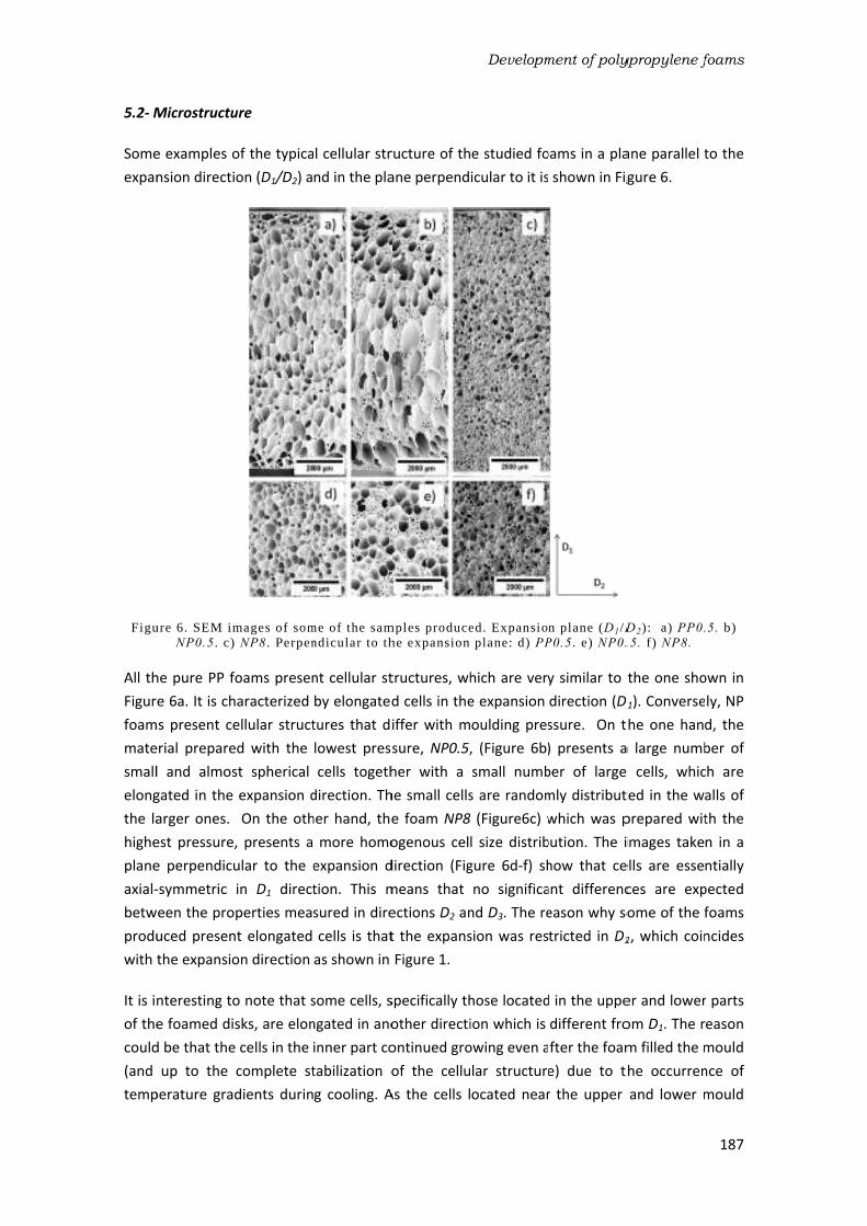
5.2- M
Some
expan
Figu
All th
Figur
foam
mate
small
elong
the la
highe
plane
axial-
betw
produ
with t
It is in
of the
could
(and
temp
Microstructu
e examples o
nsion directi
ure 6. SEM imNP0.5. c)
he pure PP f
e 6a. It is ch
ms present ce
erial prepare
l and almos
gated in the
arger ones.
est pressure,
e perpendicu
-symmetric
ween the pro
uced presen
the expansio
nteresting to
e foamed dis
d be that the
up to the
perature grad
ure
of the typica
on (D1/D2) a
mages of som NP8. Perpen
oams presen
haracterized
ellular struct
ed with the
st spherical
expansion d
On the oth
, presents a
ular to the e
in D1 direct
perties mea
nt elongated
on direction
o note that s
sks, are elon
cells in the
complete st
dients durin
l cellular str
nd in the pla
me of the samndicular to th
nt cellular st
by elongated
tures that di
lowest press
cells togeth
direction. Th
her hand, the
more homo
expansion d
tion. This m
sured in dire
cells is that
as shown in
some cells, s
ngated in ano
inner part co
tabilization o
g cooling. A
ructure of th
ane perpend
mples producehe expansion
tructures, wh
d cells in the
iffer with m
sure, NP0.5,
her with a
he small cells
e foam NP8
ogenous cel
direction (Fig
means that
ections D2 an
t the expans
Figure 1.
specifically th
other directi
ontinued gro
of the cellu
As the cells l
Developm
e studied fo
icular to it is
ed. Expansio plane: d) PP
hich are very
e expansion
oulding pres
, (Figure 6b)
small numb
s are random
8 (Figure6c) w
l size distrib
gure 6d-f) sh
no significa
nd D3. The re
sion was res
hose located
ion which is
owing even a
lar structure
ocated near
ment of poly
oams in a pla
shown in Fig
n plane (D1/DP0.5. e) NP0.
y similar to t
direction (D1
ssure. On t
) presents a
ber of large
mly distribut
which was p
bution. The i
how that ce
ant differenc
eason why so
tricted in D1
d in the uppe
different fro
fter the foam
e) due to t
r the upper
ypropylene f
ane parallel t
gure 6.
D2): a) PP0.
.5. f) NP8.
the one sho
D1). Converse
he one hand
a large numb
e cells, whic
ted in the wa
prepared wit
images take
ells are esse
ces are exp
ome of the f
1, which coin
er and lower
om D1. The r
m filled the m
he occurren
and lower m
foams
187
to the
5. b)
own in
ly, NP
d, the
ber of
ch are
alls of
th the
n in a
ntially
pected
foams
ncides
r parts
eason
mould
nce of
mould
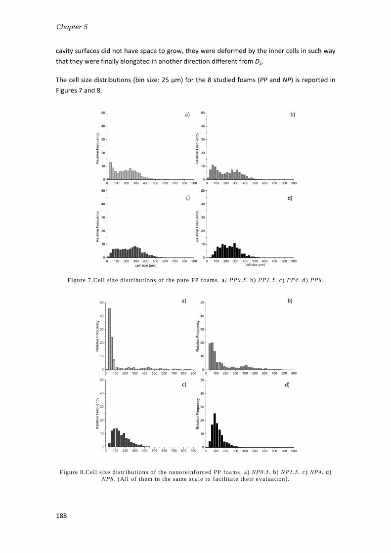
Chapter 5
188
cavity surfaces did not have space to grow, they were deformed by the inner cells in such way
that they were finally elongated in another direction different from D1.
The cell size distributions (bin size: 25 μm) for the 8 studied foams (PP and NP) is reported in
Figures 7 and 8.
Figure 7.Cell size distr ibutions of the pure PP foams. a) PP0.5. b) PP1.5. c) PP4. d) PP8.
Figure 8.Cell size distr ibutions of the nanoreinforced PP foams. a) NP0.5. b) NP1.5. c) NP4. d) NP8. (All of them in the same scale to facil i tate their evaluation).
a) b)
c) d)
0 100 200 300 400 500 600 700 800 9000
10
20
30
40
50
Re
lative
Fre
qu
en
cy
0 100 200 300 400 500 600 700 800 9000
10
20
30
40
50
cell size (m) cell size (m)
Re
lative
Fre
qu
en
cy
0 100 200 300 400 500 600 700 800 9000
10
20
30
40
50
Re
lative
Fre
qu
en
cy
0 100 200 300 400 500 600 700 800 9000
10
20
30
40
50
Re
lative
Fre
qu
en
cy
0 100 200 300 400 500 600 700 800 9000
10
20
30
40
50
Re
lative
Fre
qu
en
cy
0 100 200 300 400 500 600 700 800 9000
10
20
30
40
50
Re
lative
Fre
qu
en
cy
0 100 200 300 400 500 600 700 800 9000
10
20
30
40
50
Re
lative
Fre
qu
en
cy
0 100 200 300 400 500 600 700 800 9000
10
20
30
40
50
Re
lative
Fre
qu
en
cy
a) b)
c) d)

Development of polypropylene foams
189
The cumulative curves of both, the area occupied by the cells and the number of cells are represented in Figure 9.
Figure 9.Cumulative curves of a) occupied area and b) number of cells.
In addition, all the average parameters obtained after a detailed image analyses of the cellular
structures are shown in Table 4.
The density of all the foams produced is very similar (Table 4), regardless of the formulation
employed and the pressure applied. This fact allows evaluating the cellular structure without
the influence of the expansion ratio. All the PP foams appear to be very similar regarding the
cell size distributions (Figure 7). This is confirmed in the cumulative distributions, both for cell
number and cell area, which nearly superimpose each other (solid lines of Figure 9). On the
contrary, the NP ones present very different trends in terms of the pressure applied, not only
in the cell size distributions (Figure 8) but also in the cumulative curves (dashed lines of Figure
9) confirming what was shown qualitatively by SEM images in Figure 6.
0 100 200 300 400 500 600 700 800 900
0
20
40
60
80
100
0 100 200 300 400 500 600 700 800 900
0
20
40
60
80
100
cum
lative o
ccupie
d a
rea (
%)
PP0.5
PP1.5
PP4
PP8
NP0.5
PP1.5
NP4
NP8cum
ula
tive n
um
ber
of
cells
(%
)
Cell size (m)
a)
b)
Materials Density (kg/m3) (μm) ACΦ NSDΦ Nv(cells/cm
3) OC (%)
PP0.5 173 193.2 0.63 0.62 10.3·104 32.3
PP1.5 183 205.1 0.33 0.61 8.15·104 35.0
PP4 182 219.5 0.42 0.57 7.1·104 26.3
PP8 188 230.7 0.34 0.41 6.1·104 13.5
NP0.5 182 125.1 2.52 1.37 38.1·104 53.6
NP1.5 181 173.8 1.38 0.94 14.1·104 84.2
NP4 189 156.0 0.90 0.52 19.6·104 91.9
NP8 180 118.2 1.26 0.47 45.09·104 91.8 Table 4. Average parameters of the cellular structure and open cell content.

Chapter 5
190
One interesting feature of the foams developed, especially in the nanoreinforced foams, is the
presence of mesoporosity (small cells within the cell walls of the larger ones), which can be
quantitatively estimated from the previous plots. For instance, in the foam produced with the
lowest pressure (NP0.5) about 80% of the cells have sizes below 100µm. However, the area
that these cells occupy is below 10% constituting the reason why they can be considered as
mesoporosity (i.e. the porosity of the solid frame). This mesoporosity tends to disappear when
increasing the foaming pressure and the distribution tends to get narrower (Figure 8c and
d).For instance, on the left side of the distribution the number of cells with sizes below 50 μm
goes from more than 40% in NP0.5 to less than 5% in NP8, while on the right side, cells with
sizes larger than 300 μm represent more than 12% in NP0.5 while only 1% in NP8.
The shape of the cell size distributions is measured by the AC values (asymmetry coefficient),
which are shown in Table 4. The AC of the NP0.5 foam, for instance, is very high (2.52)
indicating a non-symmetric distribution with few large cells whose size are far from the
average value. On the contrary, as pressure increases the AC values decrease and hence, the
distributions tend to be more symmetric. In general, the cell size distribution symmetry of the
PP foams is higher than those of the NP foams because their AC values are lower. NSD is also
sensitive to the presence of the clay particles. In fact, the presence of this phase increases this
parameter, especially for the foams with a bimodal cell size distribution.
Therefore, the cellular structures of these foams were influenced by two factors: on the one
hand, by the addition of nanoclays and on the other hand, by the pressure applied during
foaming. Both aspects are discussed in more detail the following sections.
Influence of nanoclays
The addition of nanoclays clearly influenced the cell size (Φ) and cell density values(Nv).The
average cell size of all the NP foams is 143,3 µm while that of the pure foams is 212,1µm. The
same result is observed for the Nv values but in an opposite way, as the average value of NP
foams (2.9·105) is higher than that of PP foams (7.9·104). This is possibly due to a
heterogeneous nucleation of cells caused by the presence of nanoclays in the molten polymer.
The energy barrier that gas molecules have to overcome to form a single cell on the surface of
a nanoclay particle is lower than that required in the molten polymer [9]. Nanoclays also
influenced the level of interconnectivity between cells. In general the OC values of the NP
foams are higher than that of the PP foams. This is confirmed by observing the cellular
structure morphology of a pure foam (PP1.5) and the reinforced foam (NP1.5) produced with
the same process. This comparison is shown in Figure 10.

Figu
The c
cells
black
the n
obser
still s
for th
highe
proce
obser
of the
molte
strain
was o
foam
conse
Influe
The
struct
becau
the e
becau
Figur
on in
produ
shifte
contr
at th
morp
distri
struct
progr
ure 10.Cellula
cellular struc
in the form o
k arrows, con
number of i
rved in Figur
supported by
he high ope
er cell wall th
ess the cell w
rved in Figur
e molten po
en polymer e
ns (as in a fo
observed in
ms less capa
equence the
ence of foam
pressure ap
tures obtain
use it determ
expansion st
use both, Φ
e 6). There is
ncreasing p
uced in NP f
ed from 0.5
radictory bec
e lowest (0.
phology of th
bution of c
ture with a
ressively dec
ar structure o
cture of the
of holes and
nfirming wha
nterconnect
re 10. In spite
y walls. Neve
n cell conte
hinning durin
wall membra
re 9. It seem
lymer. Branc
experiences
oaming proc
previous wo
able of sup
y break inter
ming pressure
pplied over
ned. This p
mines the am
tage [48]. Nev
and Nv, are v
s a slight ten
ressure, but
foams. In thi
MPa to 1.5
cause the hig
.5 MPa) and
hese foams
cell sizes wh
narrower ce
crease as the
of (a) PP1.5
NP1.5 foam
ruptures wi
at was meas
tions in the
e of the high
ertheless, th
nt values. T
ng expansion
ane is so thin
s that the pr
ched PPs pre
a sudden inc
cess) [46]. How
orks in litera
porting the
rconnecting
e
the polyme
processing p
mount of blo
vertheless, P
very similar
ndency for th
t these var
s case, the c
MPa. In fact
ghest cell de
d the highest
is very differ
hile NP8 is
ell size distr
e pressure inc
foam and (b)walls.
m shows a h
ithin the cell
ured by gas
pure foam
h interconnec
hese walls pr
The formatio
n. At some sp
n that it brea
resence of cl
esent the str
crease of ext
wever the p
ature [47]. T
pressure o
the correspo
er/blowing a
parameter is
owing agent
PP foams do
(this was als
he cell size to
riations are
cell density v
t, the genera
ensity values
t (8 MPa) p
rent. NP0.5
characterize
ribution. Thi
creases.
Developm
) NP1.5 foam
igh number
walls which
picnometry
is considera
ctivity levels
resent small
on of this str
pecific expan
ks, thus prod
ays could aff
rain-hardenin
tensional vis
presence of c
This fact wou
of the gas
ondent cells
agent system
s very impo
dissolved in
o not seem
so observed
o increase an
negligible
values drasti
al trend obta
s were obtai
ressures. Ho
is character
ed for prese
s is confirm
ment of poly
m. Arrows ind
of interconn
are indicate
(OC=84.2%)
ably lower (
of the NP fo
holes, whic
ructure coul
nsion ratio d
ducing the h
fect the rheo
ng phenome
scosity when
clays reduce
uld make th
during expa
sharing the w
m also affe
ortant in fo
n the molten
to be influe
in the cell siz
nd the cell de
when comp
cally fall whe
ained with N
ned with the
owever, the
ized for pres
enting a mo
ed by the N
ypropylene f
dicate broken
nections bet
ed in the ima
. On the con
(OC=35%) a
oams, the ce
ch are respo
d be caused
uring the foa
holes and rup
ological beha
enon by whic
n stretched a
es this effect
e cell walls
ansion and
wall.
ected the ce
oaming proc
n polymer pr
enced by pre
ze distributio
ensity to dec
pared with
en the press
NP foams is r
e foams prod
cellular stru
senting a bim
ore homoge
NSD values,
foams
191
n cell
tween
age by
ntrary,
s also
lls are
nsible
d by a
aming
ptures
aviour
ch the
t high
t. This
in NP
as a
ellular
cesses
rior to
essure
ons of
crease
those
sure is
rather
duced
ucture
modal
neous
which

Chapter 5
192
An explanation for this behaviour was found in the TGA measurements previously performed
over the two solid formulations (PP and NP). Figure 4 showed a clear reduction of the
temperature (ADC onset) at which the blowing agent starts to decompose when adding
nanoclays. The foaming temperature was decreased when using the NP formulation (190ºC) in
order to compensate for this effect and to generate the same amount of gas in the two
formulations. Nevertheless, the results obtained with the isotherms (Figure 5) indicated that
the blowing agent in the presence of nanoclays, even after decreasing the foaming
temperature 10ºC, was able to generate a higher amount of gas than in the pure formulation
(weight loss at 900 s) (Table 3).
This fact is consistent with the cellular structures obtained. In the case of the pure
formulations, all the gas generated was able to be dissolved within the molten polymer in all
the range of external pressures studied (from 0.5 to 8 MPa). For this reason, the cellular
structures obtained are very similar. However, the amount of gas generated in the
nanoreinforced formulations (NP) was higher, which made the polymer/blowing agent system
more sensitive to pressure variations. This means that the amount of gas dissolved at high
pressures (8 MPa)could be higher than that dissolved at low pressures (0.5 MPa). The cell size
and cell density are parameters of the cellular structure, which depend on the amount of gas
dissolved within the polymer. The higher the amount of gas dissolved the higher the
nucleation rate and as a consequence, the number of cells in the final foam. This is why the cell
density and cell size values obtained with the NP varied according to the pressure exerted.
An additional effect, in combination with the previous one, could explain the formation of the
bimodal cell size distributions in the NP foams. The gas molecules, which could not be
dissolved into the polymer matrix when employing low external pressures, formed cells even
before releasing the external pressure applied. This involved a foaming process with two
nucleating stages. A few cells nucleated in a first step (during the application of the external
pressure) and hence, they had more time to grow, resulting in the formation of large cells,
while most of the cells nucleated in a second stage (after releasing the external pressure) with
less space and time to grow and therefore, creating smaller sizes. A similar effect was observed
in a previous work in which a two-step depressurization batch process was used for the
formation of a bimodal cellular structure but in this case using polystyrene foams and CO2 as
the physical blowing agent [49].
The open cell content is another parameter, which is also connected with the amount of gas
dissolved. In the NP foams produced at high pressures, the amount of gas dissolved into the
molten polymer grows and therefore, the pressure inside the cells in the expansion process is
higher, making the cell walls more prone to break. The results in Table 4 confirm the previous
hypothesis because the foams NP4 and NP8 present higher OC values.
Anisotropy evaluation
Table 5 reports the average values of cell size in the expansion direction (Φ1) and in the
transversal direction (Φ2) for all the studied foams. The average anisotropy ratio R (calculated

Development of polypropylene foams
193
using equation 12) and the average anisotropy ratio weighted over the area of each cell Rw
(calculated using equation 13), are also shown.
Materials Φ1 (μm) Φ2(μm) R Rw
PP0.5 159.0±126 111.2±81 1.43±0.66 1.49±1.61
PP1.5 165.4±113 111.8±75 1.48±1 1.54±0.87
PP4 179.9±108 124.9±73 1.41±0.58 1.49±0.41
PP8 202.4±88 158.1±67 1.28±0.61 1.35 ±0.63
NP0.5 106.5±131 78.9±123 1.35±0.55 1.75±0.49
NP1.5 144.2±151 102.3±104 1.41±0.57 1.64±0.32
NP4 145.1±94 126.2±72 1.15±0.42 1.09±0.56
NP8 101.5±82 76.3±76 1.33±0.45 1.26 ±0.43
Table 5.Average cell size in the expansion (Φ1) and transversal (Φ2) directions. Average anisotropy ratio in the expansion direction R(equation 12)and Rw. (equation 13).
The results show that in all the cases, Φ1>Φ2 and hence, R> 1. This indicates that all the foams
produced present anisotropic structures, which is consistent with the fact that the expansion
of the polymer was restricted to only one direction (D1). However, the degree of anisotropy
and the tendencies with respect to the pressure applied seem to change when the anisotropy
ratio of each cell is weighted with their correspondent occupied area. The plots of Figure 10
show the values of R and Rw for all the PP and NP foams.
Figure 11.a) R and Rw values of PP foams. b) R and Rw values of NP foams.
There is no apparent trend regarding foaming pressure when only the R values are considered
and in general the NP foams present lower anisotropy ratios that the PP foams. This is caused
by the great number of small cells present in the NP foams produced with the lower pressures,
which are isotropic. On the contrary, when considering Rw a clear trend appears in the case of
the NP foams. The Rw values of the foams produced with the lower pressures (NP0.5 and
NP1.5) are clearly higher than those of the correspondent pure foams (PP0.5 and PP1.5) and
they seem to decrease with the applied pressure. The results of Rw seem to be consistent with
the cellular structures shown in Figure 6 and with the explanation given before for the
formation of the bimodal cell size distributions. The foaming process of the NP foams
produced at low pressures is controlled by two nucleation stages. The cells formed during the
first nucleation stage not only had more time to grow but also more space and therefore, they
could grow with a greater elongation. However, the cells formed during the second stage, had
less space and less time. As a consequence they became practically isotropic.
1
1,1
1,2
1,3
1,4
1,5
1,6
1,7
1,8
PP0.5 PP1.5 PP4 PP8
R R
Rw
1
1,1
1,2
1,3
1,4
1,5
1,6
1,7
1,8
PP0.5 PP1.5 PP4 PP8
R R
Rw
a) b)

Chapter 5
194
Although no unique correlation is observable, it can be supposed that different combinations
of R and cell size will have a different influence on the mechanical behaviour of foams. In fact,
according to the classic beam theory, that has been used to analyse the deformation
mechanisms in cellular materials, the elastic deformation of cells depends on the third power
of their size. This means that bigger cells contribute much more than smaller ones to specimen
deformation [50] and their anisotropy has a greater influence on the elastic modulus of the
material. For this reason Rw is then considered to better represent the anisotropic structure of
the materials. The results of the next section will prove that this assumption is correct.
5.3- Mechanical behaviour
Foamed structures subjected to small deformations react elastically with a modulus dependant
on its microstructure and, in the case of anisotropic foams, on the direction of the load. The
results of the mechanical tests are summarized in Table 6. The Eexp values represent the
average over the moduli measurements in the expansion direction (D1).E2andE3 are the
averages of the moduli in the transversal directions measured on the samples along directions
D2 and D3. In the majority of the analysed materials, E2≈E3, hence, their average (Etransv) is taken
as the modulus of the materials in the transversal direction. The ratio of modulus (Eexp/Etransv) is
reported too and indicates the mechanical anisotropy of the material
Material Eexp[MPa] E2 [MPa] E3[MPa] Etransv[MPa] Eexp/ Etransv
PP0.5 81.4±1.2 32.7±4.1 33.8±1.4 33.2±4.3 2.4±0.3
PP1.5 96.2±1.3 33.8±3.2 39.4±4.1 36.6±5.2 2.6±0.4
PP4 96±5.7 39±2.8 44±1.6 41.5±3.2 2.3±0.2
PP8 66.3±2.6 30.6±0.8 44±1.3 37.3±1.6 1.8±0.1
NP0.5 134.4±7.7 33±4.4 55±2.7 44.0±5.2 3.0±0.4
NP1.5 118.3±4.9 50.1±6.5 44.4±2.5 47.2±6.9 2.5±0.4
NP4 73.2±8.4 47.6±2.5 48.5±4.5 48.0±5.2 1.5±0.2
NP8 78±5.4 33.4±3.2 30±3.8 31.7±10.4 2.5±0.8
Table 6.Compressive moduli values.
Figure 12 represents both, the Eexp and the Etransv values, as a function of Rw for all the foams
produced.
Figure 12.a) Eexp versus Rw . b)Et ransv versus Rw.
Rw
1,0 1,1 1,2 1,3 1,4 1,5 1,6 1,7 1,8
Etr
an
sv
0
10
20
30
40
50
60
70
Rw
1,0 1,1 1,2 1,3 1,4 1,5 1,6 1,7 1,8
Eexp
60
70
80
90
100
110
120
130
140
PP
NP
a) b)

Development of polypropylene foams
195
These plots prove that Rw has a clear influence on the elastic modulus when the foams are
measured in the expansion direction (Eexp). The trend obtained indicates that the elastic
modulus increases with the Rw values. Therefore, the large anisotropic cells characteristic of
the NP foams produced at low pressures have a significant influence on the measured
mechanical properties. In the case of the measurements performed in the transversal direction
(Etransv) there is not any apparent trend with Rw. However, in this direction (Etransv) it is possible
to observe that practically all the NP foams present higher values of the modulus than the PP
foams. This fact proves the reinforcing effect of nanoclays on the polymer matrix within the
cell walls and struts because even though they promote high levels of interconnectivity in
these foams (Table 4), the modulus obtained are higher.
Mechanical properties can be correlated with structural characteristics of the materials by
means of the models presented in the introductory section. Those models demonstrated to be
predictive of the behaviour of cellular materials while they follow these conditions: periodicity
of the cellular structure, narrow cell size distributions, low relative density and open cell
structures [35,39]. The materials which are the object of this investigation only partly satisfy
these conditions. It is nonetheless also worth attempting to apply the models also to polymer
foams with higher densities and partially open cell structures, like the PP-based ones produced
in this work. In Figure 12a the experimental data for stiffness ratio (Eexp/Etransv) are compared
with the Huber & Gibson relation for open cell foams (fs=1) obtained using equation 1 and with
the Huber & Gibson relation for closed cell foams (equation 2) and different values of fs . In
Figure 13b the comparison is carried out with the prediction given by the elongated Kelvin cell
model with different values of Q obtained using equation 3 (dashed lines) [39]. The elongated
Kelvin cell model curves are calculated for different values of Q (2, √ , 1) and for a relative
density similar to that of the studied foams (ρf/ρs= 0.19).
Figure 13.Moduli ratio of studied materials (PP and NP foams) reported as a function of R (ful l dots) and as a function of Rw (hollow dots) and comparison with l i terature models. a,b) Huber-
Gibson for open cell foams (f s=1) and elongated Kelvin cell model (f s=1). c,d) Huber-Gibson for closed cell foams and different values of f s.
These analytical models fit well with the experimental results for NP foams when considering
low Rw values but they failed to describe the mechanical behaviour of foams with Rw1.6. On
the one hand, the NP foams produced at high pressures (Rw=1,09 and 1,26) fit well with the
1.0 1.1 1.2 1.3 1.4 1.5 1.6 1.7 1.8 1.9 2.00
1
2
3
4
5
6
7
8
1.0 1.1 1.2 1.3 1.4 1.5 1.6 1.7 1.8 1.9 2.00
1
2
3
4
5
6
7
8
Q= 2
Q=1
Q=2
Ee
xp/E
tra
nsv
RwR
w
fs=0.3
fs=0.4
fs=0.5fs=0.6
fs=0.7
fs=1
Q= √ Q= 1
Q= 2
a) b)

Chapter 5
196
Huber-Gibson model for open cell foams. These foams satisfy two conditions of the model
because they present highly homogeneous cell size distributions and high open cell contents.
On the other hand, the PP foams seem to follow the trend marked by the Huber-Gibson model
for closed cell foams when fs is in between 0.3 and 0.4. This is in good agreement with the fact
that the pure foams present low open cell contents. However, they also fit well with the Kelvin
model when = √ , which describes the mechanical behaviour of open cell foams. This may
be caused by the possibility of adjusting the model with the morphological parameter Q. On
the contrary, when considering high Rw values (Rw1.6) the models do not follow the trend
marked by the experimental values. This could be due to the presence of bimodal cell size
distributions, which make the cellular structure of these foams non periodic and non-
homogeneous. Therefore, it seems to be necessary to adjust the previous models or to
develop new ones in order to be able to describe properly the mechanical properties of these
medium-low density foams with non-homogeneous cell size distributions properly.

Development of polypropylene foams
197
6- Conclusions
The use of the ICM technology allowed the production of PP foams with densities lower than
0.2 g/cm3 and with very different cellular structures depending on the pressure applied and on
the presence of nanoclays in the formulations. Cellular structural parameters such as cell size,
cell density, anisotropy ratio, etc. were accurately measured by means of an user-interactive
digital image software that allowed a proper correlation of these parameters with the
mechanical properties obtained.
The presence of nanoclays not only promoted heterogeneous nucleation of cells (cell size was
reduced) but also induced a catalytic effect in the blowing agent decomposition reaction,
which involved the generation of higher amounts of gas and the formation of a bimodal cell
size distribution (mesoporosity) in the specimens produced at the lowest pressures. A two-
stage nucleation process could be the reason underlying the presence of two populations of
cells, in which the large cells nucleated in the first stage and the small cells, but more
numerous, in the second stage. Moreover, nanoclays induced ruptures of the cell walls
producing partially open cellular structures.
The unidirectional expansion of the polymer in the ICM process promoted the formation of
anisotropic cellular structures. Cells anisotropy was analysed and different trends for each
material were observed. In particular, it was noted that the smaller cells of the NP foams
(mesporosity) tend to have rounded shape. Taking into consideration this fact, anisotropy ratio
weighted over the cell area (Rw) was taken as being a more representative parameter of the
foam structure.
These morphological changes had a measurable effect on the elastic moduli of the foams
measured in compression, which reflected the structural anisotropy morphologically observed.
The modulus in the expansion direction is, in fact, higher than that in the transversal direction
in all the studied foams and there is a clear relation between the modulus measured in the
expansion direction and the cellular anisotropy. Moreover, the incorporation of clays, apart
from the previously mentioned modification of the cellular structure allowed the improvement
of the elastic mechanical properties in all the analysed directions.
Lastly, the application of two different micromechanical relations, based on two different cells
(rectangular and tetrakaidecahedron cell), was attempted. Acceptable correspondence
between experimental data and the Huber-Gibson model, both for open cell and closed cell
foams, was obtained when considering low Rw because in this case, the cellular structures are
more homogeneous in terms of cell size distribution satisfying one of the main conditions of
this model. However, in the case of the foams with the bimodal cell size distribution there was
not a good correlation, which could be due to the non-periodicity and lack of homogeneity in
these structures.

Chapter 5
198
References
[1] Klempner, D. and Frisch, K.C. Handbook of polymeric foams and foam technology. Hanser
Publishers.1991.
[2] Bouix, R.; Viot, P. and Lataillade, J.L. Polypropylene foam behavior under dynamic loadings: strain rate, density and microstructure effects. International journal of impact engineering. 39, 329-342.2009.
[3] Zhai, W.; Kim, Y.W. and Park, C.B. Steam-chest molding of expanded polypropylene foams. 1. dsc simulation of bead foam processing. Industrial and engineering chemistry research. 49, 9822-9829. 2010.
[4] Naguib, H.E. and Park, C.B. Strategies for achieving ultra-low density polypropylene foams. Polymer engineering and science. 42, 1481-1492. 2002.
[5] Suh, K.W.; Park, C.P.; Maurer, M.J.; Tusim, M.H.; Genova, R.; Broos, R. and Sophiea, D.P. Lightweight Cellular Plastics. Advanced materials. 12, 1779-1789.2000.
[6] Stange, J. and Münstedt, H. Effect of long-chain branching on the foaming of polypropylene with azodicarbonamide. Journal of cellular plastics. 42, 445-467. 2006.
[7] Naguib, H.E. and Park, C.B. Strategies for achieving ultra low-density polypropylene foams. Polymer engineering and science. 42, 1481-1492. 2002.
[8] Nam, G.J.; Yoo, J.H. and Lee, J.W. Effect of long-chain branches of polypropylene on rheological properties and foam-extrusion performances. Journal of applied polymer science. 96, 1793-1800. 2005.
[9] Lee, L.J.; Zeng, C.; Cao, X.; Han, X.; Shen, J. and Xu, G. Polymer nanocomposite foams. Composites
Science and Technology. 65, 2344-2363.2005.
[10] Zhai, W.; Kuboki, T.; Wang, L. and Park, C.B. Cell structure evolution and the crystallization behavior of polypropylene/clay nanocomposites foams blown in continuous extrusion. Industrial
Engineering Chemistry. 49, 9834-9845. 2010.
[11] Zhai, W. and Park, C.B. Effect of nanoclay addition on the foaming behavior of linear polypropylene-based soft thermoplastic polyolefin foam blown in continuous extrusion. Polymer
Engineering and Science. 51, 2387-2399. 2011
[12] Zheng, W.G.; Lee, Y. H. and Park. C.B. Use of Nanoparticles for improving the foaming behaviors of Linear PP. Journal of Applied Polymer Science. 117, 2972-2979. 2010.
[13] Chaudhary, A.K. and Jayaraman K. Extrusion of linear polypropylene–clay nanocomposite foams. Polymer Engineering & Science. 51, 1749-1756, 2011.
[14] Bhattacharya, S.; Gupta, R.K.; Jollands, M. and Bhattacharya, S.N. Foaming behavior of high-melt strength polypropylene/clay nanocomposites. Polymer Engineering & Science. 49, 2070-2084. 2009.
[15] Nam, P.H.; Maiti, P.; Okamoto, M. and Kotaka, T. Foam processing and cellular structure of polypropylene/clay nanocomposites. Polymer engineering & science. 42, 1907-1918.2002
[16] Taki, K.; Yanagimoto, T.; Funami, E.; Okamoto, M. and Ohshima, M. Visual observation of CO2
foaming of polypropylene-clay nanocomposites. Polymer Engineering & Science. 44, 1004-1011, 2004.
[17] Oh, K.; Seo, Y.P.; Hong, S.M.; Takahara, A.; Lee, K.H. and Seo, Y. Dispersion and reaggregation of nanoparticles in the polypropylene copolymer foamed by supercritical carbon dioxide. Physical
Chemistry Chemical Physics. 15, 11061-11069. 2013
[18] Dolomanova, V; Kumar, V.; Pyrz, R.; Madaleno, L.A.O.; Jensen, L.R. and Rauhe, J.C.M. Fabrication of microcellular pp-mmt nanocomposite foams in a sub-critical CO2 process. Cellular Polymers. 31, 125-144. 2012.
[19] Jiang, X.L.; Bao, J.B.; Liu, T.; Zhao, L.; Xu, Z.M. and Yuan, W.K. Microcellular Foaming of Polypropylene/Clay Nanocomposites with Supercritical Carbon Dioxide. Journal of Cellular
Plastics. 45, 515-538. 2009

Development of polypropylene foams
199
[20] Jiang, M.; Li, H.R.; Fang, D.; Liu, L.; Tai, Q.L. and Li, L.C. Structure-Property Relationship in
Injection Molded Polypropylene/Clay Composite Foams. Materials and Manufacturing Processes. 29, 160-165, 2014.
[21] Antunes, M.; Velasco, J.I.; Realinho, V. and Solorzano E. Study of the Cellular Structure Heterogeneity and Anisotropy of Polypropylene and Polypropylene Nanocomposite Foams. Polymer Engineering &Science. 49, 2000-2413. 2009.
[22] Ma, Y.; Pyrz, R.; Rodriguez-Perez, M.A.; Escudero, J.; Rauhe, J.C. and Su. X. X-ray microtomographic study of nanoclay-polypropylene foams. Cellular Polymers.30, 90-110, 2011.
[23] Rodríguez-Pérez, M.A.; Lobos, J.; Pérez-Muñoz, C.A.; de Saja, J.A.; González, L. and del Carpio B.M.A. Mechanical behaviour at low strains of LDPE foams with cell sizes in the microcellular range: advantages of using these materials in structural elements. Cellular polymers. 27, 347-362.2008.
[24] Rodríguez-Pérez, M.A.; Lobos, J.; Pérez-Muñoz, C.A. and de Saja, J.A. Mechanical Response of polyolefin foams with high densities and cell sizes in the microcellular range. Journal of cellular
plastics. 45, 389-403. 2009.
[25] Román-Lorza, S. Formulación y caracterización de materiales celulares retardantes de llama libres de halógenos basados en poliolefinas. Tesis Doctoral. Universidad de Valladolid. 2010.
[26] Román-Lorza, S.; Rodríguez-Pérez, M.A. and de Saja. J.A. Cellular structure of halogen-free flame retardant foams based on LDPE. Cellular polymers. 28, 249-268. 2009.
[27] Román-Lorza, S.; Rodríguez-Pérez, M.A.; de Saja, J.A. and Zurro, J. Cellular structure of EVA/ATH halogen-free flame retardant foams. Journal of cellular plastics. 10, 1-21. 2010.
[28] Román-Lorza, S.; Sabadell, J.; García-Ruiz, J.J.; Rodríguez-Pérez, M.A. and de Saja, J.A. Fabrication and characterization of Halogen Free Flame Retardant Polyolefin Foams. Materials science forum 636/637, 98-205. 2010.
[29] Rodríguez-Pérez, M.A.; Simões, R.D.; Constantino, C.J.L. and de Saja, J.A. Structure and physical properties of EVA/Starch precursor materials for foaming applications. Journal of applied polymer
science. 212, 2324-2330. 2011.
[30] Rodríguez-Pérez, M.A.; Simões, R.D.S.; Román-Lorza, M.; Álvarez-Laínez, C.; Montoya-Mesa, C.; Constantino, C.J.L. and J.A. de Saja. Foaming of eva/starch blends: characterization of the structure, physical properties and biodegradability. Polymer engineering and science. 52, 62-70. 2012.
[31] Gibson, L.J. and Ashby, M.F. Cellular Solids: Structure and Properties. 2th ed. Cambridge
University Press: Cambridge. 1997.
[32] Christensen, R.M. Mechanics of low density materials. J Mech Phys Solids 1986; 34: 563-578.
[33] Zhu, H.X, Knott, J.F, Mills N.J. Analysis of the elastic properties of open-cell foams with tetrakaidecahedral cells. Journal of the Mechanics and Physics of Solids. 45, 319-343. 1997
[34] Warren, W.E and Kraynik, A.M. Foam mechanics: The linear elastic response of two dimensional spatially periodic cellular materials. Mechanics of Materials. 6, 27-37. 1987
[35] Huber, A.T and Gibson, L.J. Anistropy of polymer foams. Journal of materials science. 23, 3031-3040. 1998.
[36] Thomson, W. (Lord Kelvin). On the division of space with minimum partitional area. Philosphical magazine. 24, 503-514. 1887.
[37] Gong, L.; Kyriakides, S and Jang, W.Y. Compressive response of open cell foams. Part I: morphology and elastic properties. International journal of solids and structures. 42,1355-1379. 2005.
[38] Gong, L.; Kyriakides, S. and Triantafyllidis, N. On the stability of kelvin cell foams under compressive loads. Journal of the mechanics and physics of solids. 53, 771-794. 2005.
[39] Sullivan, R.M.; Ghosn, L.J. and Lerch, B.A. A general tetrakaidecahedron model for open-celled foams. International journal of solids and structures. 45, 1754-1765. 2008.
[40] Sullivan, R.M and Ghosn, L.J. Shear moduli for non-isotropic, open cell foams using a general elongated Kelvin foam model. International journal of engineering science. 47, 990-1001.2009.

Chapter 5
200
[41] Hamilton, A.R.; Thomsen, O.T.; Madaleno, L.A.O.; Jensen, L.R.; Rauhe, J.C.M. and Pyrz, R.
Evaluation of the anisotropic mechanical properties of reinforced polyurethane foams. Composites science and technology. 87, 210-217. 2013.
[42] Pinto, J.; Solórzano, E.; Rodriguez-Perez, M.A. and de Saja, J.A. Characterization of the cellular structure based on user-interactive image analyses procedures. Journal of cellular plastics. 49, 555-575. 2013.
[43] Kumar, V. Process synthesis for manufacturing microcellular thermoplastic parts. PhD. Thesis. Massachusetts Institute of Technology. Cambridge, MA. 1988.
[44] Weller, J.E. and Kumar V. Solid-state microcellular polycarbonate foams. I. The steady-state process space using subcritical carbon dioxide. Polymer engineering & Science. 50, 2160-2169.2010.
[45] Bhatti, A.S. and Dollimore, D. The thermal decomposition of azodicarbonamide. Thermochimica
Acta. 76, 63-67. 1984.
[46] Spitael, P. and Macosko, C.W. Strain hardening in polypropylenes and its role in extrusion foaming. Polymer Engineering and Science. 44, 2090-2100.2004.
[47] Laguna-Gutierrez, E.; Lopez-Gil, A.; Saiz-Arroyo, C.; Van Hooghten, R.; Moldenaers, P.; Rodriguez-Perez, M.A. Extensional rheology/cellular structure/mechanical behaviour relationships in HMS PP/montmorillonite foams. Laguna-Gutierrez, E.; Lopez-Gil, A.; Saiz-Arroyo, C.; Van Hooghten, R.; Moldenaers, P.; Rodriguez-Perez, M.A. 2015. Submitted
[48] Lee, S.T.; Park, C.B. and Ramesh, N.S. Polymeric Foams. Science and Technology. Taylor and
Francis Group. 2007.
[49] Bao, J.B.; Liu, T.; Zhao, L. and Hub, G.H. A two-step depressurization batch process for the formation of bi-modal cell structure polystyrene foams using scCO2. Journal of Supercritical
Fluids. 55, 1104-1114. 2011.
[50] Fazekas, A.; Dendievel, R.; Salvo, L. and Bréchet Y. Effect of microstructural topology upon the stiffness and strength of 2D cellular structures. International Journal of Mechanical Sciences. 44, 2047-2066. 2002.

5.4- C
The m
First
empl
leadin
the o
distri
(15 w
sense
conte
wt% t
close
conte
foam
(com
sensi
cellul
agent
Figur
The I
rigid
produ
applic
foam
allow
involv
(cubi
prope
reinfo
empl
variat
large
aniso
effect
Conclusions
main objecti
of all, the
oyed were
ng to the pro
one hand, ce
butions wer
wt%). The op
e that the i
ent. On the o
the cell size
d cell foam
ent prevails o
ms. This was
pression, te
tive to cellul
lar structure
t content in
re 5.2. PP foa
CM route pr
foams, whic
uction of foa
cations such
ming perform
wed the prod
ved a reduc
c cell) in w
erties. With
orced with
oyment of lo
tions such a
number of
otropic cells.
t induced by
ives of this t
production
successfully
oduction of
llular structu
e achieved b
pen cell cont
ncrements o
other hand, w
increased a
s with grea
over that of
evaluated
ensile and be
lar structure
e modificatio
foams produ
ams produced
roved to be a
ch could be
ams based on
h as PET and
mance. In the
uction of low
ction of mec
hich the rel
the aim of
nanoclays. T
ow foaming
s the appea
small and i
The appeara
y nanoclays
thesis regard
parameters
optimized f
PP foams wi
ures with cel
by applying h
tent of these
of the expa
when the blo
nd the open
ter mechan
cell size whe
by mechan
ending). The
variations a
ons (cell size
uced with the
d with differea) 1
a suitable pr
applied for
n PP able to
d PVC foams
e work perfo
w density PP
chanical prop
lative densit
decreasing
The presenc
pressures (b
rance of bim
sotropic cel
ance of the d
in the blowi
ding the pro
s of the IC
for this poly
ith varied ex
ll sizes below
high initial p
e foams was
nsion ratio
owing agent
n cell content
ical perform
en determini
ical tests pe
e collapse, y
as the elastic
e increment
e same expa
ent contents 5 %.wt b) 1%
roduction ro
r foaming a
replace mor
s require th
ormed in sec
P foams (ρ <
perties as p
ty is the fu
the role pla
ce of nanoc
below 4 MPa
modal distrib
ls are surro
double popu
ng agent de
Developm
oduction of
M foaming
ymer during
xpansion rati
w 100 m an
ressures and
s influenced
involved an
was drastica
t decreased
mance. The r
ing the stiffn
erformed un
yield and be
modulus. Fi
t) induced w
ansion ratio (
of ADC and %.wt.
ute to obtai
ny thermop
re common m
e use of a p
ction 5.3, a
200kg/m3).
redicted in t
ndamental p
ayed by den
lays within
a) promoted
utions of ce
unded by a
ulation of cel
composition
ment of poly
PP foams ha
route and
g the first w
ios and cellu
nd with a ver
d high blowin
by the expa
n increment
ally reduced
resulting in
role played
ness (elastic m
nder differe
ending stren
gure 5.2 sho
when decrea
(1.6).
the same exp
n non-crossl
lastic polym
materials ap
polymer mat
branched PP
This reducti
the Gibson a
parameter d
sity, the po
the polyme
d interesting
ll sizes (Figu
lesser numb
ls is explaine
n reaction, w
ypropylene f
ave been fu
the formula
work (Section
ular structure
ry narrow ce
ng agent con
ansion ratio
of the ope
from 15 wt%
the product
by the ope
modulus) of
ent configura
gths were n
ows an exam
asing the bl
pansion ratio
linked and sh
mer. Howeve
plied to stru
trix with a h
P was used
ion of densit
and Ashby m
determining
lymer matri
er matrix an
cellular stru
ure 5.3) in w
ber of bigge
ed by the cat
which involve
foams
201
lfilled.
ations
n 5.2)
es. On
ell size
ntents
in the
en cell
% to 1
ion of
en cell
these
ations
not as
mple of
owing
o (1.6)
haped
er, the
ctural
higher
which
ty also
model
foam
x was
d the
ucture
hich a
er and
talytic
ed the

Chap
202
gene
sensi
fact t
proce
Figur
Figu
The c
low p
sizes
found
and
nano
prope
direct
polym
The a
featu
simila
These
one d
these
mech
mech
aniso
prope
morp
aniso
the s
cells
Finall
cellul
mode
when
pter 5
ration of a h
tive to press
together wit
ess, which w
e 5.3a.
ure 5.3.Nanoc
characteristi
pressures ev
(Figure 5.3b
d in polymer
with lower
reinforced f
erties when
tion. This fa
mer matrix w
anisotropic c
ure was dete
ar to those o
e anisotropic
direction (IC
e foams was
hanical prope
hanical aniso
otropy (R), h
erties of t
phological a
otropy ratio a
maller cells,
(measured in
ly, common
lar structure
el (tetrakaid
n foams with
higher amou
sure variatio
th the emplo
was respons
clay reinforce
c bimodal c
volved to ver
b). In this cas
rs reinforced
r cell sizes
foams, in spi
measured
act is a clear
within the ce
character of
erminant in
of the foams
c structures w
CM process).
s tackled by
erties in com
otropy behav
highlighting
these PP-ba
nisotropy (R
and cell size.
which were
n two dimen
models em
s, such as th
ecahedron c
h Rw< 1.6 we
unt of gas. T
ons (at least
oyment of lo
ible for the
ed PP foams:high p
ell size distr
ry homogene
se, the heter
d with partic
s than thos
ite of their h
not only in
r indicator o
ll walls and s
f these foam
order to pr
employed in
were the res
. The study
y characteriz
mpression in
viour (Eexp/E
the importa
ased foams
R) was esta
. The bigger
e practically i
nsions) was w
mployed to
e Huber-Gib
cells)provide
ere considere
herefore, th
in the rang
ow foaming
formation
: a)produced pressures (80
ribution of t
eous cell siz
rogeneous n
cles prevails,
se obtained
higher open
the expans
of the reinfo
struts.
ms was stud
roduce PP b
n the market
sult of restric
of the mor
zing the cel
the linear-e
Etransv) perfec
ance of this
s. A differe
ablished bas
cells present
isotropic. Fo
weighted by
describe th
bson model (
ed a good c
ed. However
e polymer/b
e of pressur
pressures ca
of two pop
at low press0MPa).
the nanorein
e distributio
ucleation ph
making thes
d with pur
cell content
ion directio
rcement ind
died in detai
based foams
t, which pres
cting the exp
phological a
llular structu
elastic region
ctly resemble
structural p
ent method
sed on the
ted higher e
or this reason
their area (R
he mechanic
rectangular
correlation w
r, in the case
blowing agen
res studied i
aused a two
ulations of c
ures (0.5 MP
nforced foam
ons of lower
henomenon,
se foams mo
re foams.
ts, present b
n but also i
duced by nan
l because th
s with mech
ent more iso
pansion of th
and mechani
ure (image
n (compressi
ed that of t
parameter in
dology to
correlation
longations (a
n, the shape
Rw).
cal behaviou
prismatic ce
with the exp
e of foams w
nt system is
in this work)
o-stage nucle
cells as sho
Pa) b) produc
ms produced
than averag
, which is typ
ore homoge
Moreover,
better mech
in the trans
noparticles
his morphol
hanical prop
otropic struc
he polymer to
ical anisotro
analysis) an
ive modulus
the morphol
n the mech
characterize
n found bet
anisotropies
anisotropy
ur of aniso
ells) and the
perimental r
with high Rw v
more
). This
eation
wn in
ced at
d with
ge cell
pically
neous
these
anical
versal
in the
ogical
perties
ctures.
o only
opy of
nd the
s). The
ogical
anical
e the
tween
) than
of the
tropic
Kelvin
results
values

Development of polypropylene foams
203
and with a bimodal distribution of cell sizes there was not a good correlation. These models
are suitable to predict the mechanical properties of low-density and open-cell foams with
highly periodic cellular structures and these kinds of PP foams do not fulfil these conditions
entirely, which could be the reason for the lack of correlation.
All the work developed in this chapter resulted in the production of PP foams with very high
mechanical performances and with varied cellular structures that make them a very promising
alternative to the current foams employed in the market of structural lightweight components,
such as the core of sandwich panels. For this reason, this development was used to elaborate a
patent, which is included in an ANEX of this thesis. Moreover, a comparative study of the
mechanical properties of these PP foams with respect to those of PVC and PET foams is also
included in Chapter 6.


CHAPTER 6:
PRODUCTION OF PROTOTYPES. APPLICABILITY OF THE
DEVELOPED MATERIALS


Contents
6.1- Introduction .......................................................................................................................... 209
6.2- Bioderived and biodegradable food-packaging trays based on TPS .................................. 211
6.2.1- Solid and flexible starch-based trays .............................................................................. 211
6.2.2- Foamed rigid trays .......................................................................................................... 216
6.2.3- Economic evaluation. ..................................................................................................... 218
6.2.4- Biodegradability tests ..................................................................................................... 221
6.2.5- Conclusions .................................................................................................................... 225
6.3- Non cross-linked PP foamed panels as the cores of sandwich panels .......................... 226
6.3.1- An alternative rigid foam for structural applications in the market: ANICELL ............... 228
6.3.2- Comparison with PVC and PET foams ............................................................................ 230
6.3.3- Conclusions .................................................................................................................... 233

Chapter 6
208

Production of prototypes
209
6.1- Introduction
The formulations developed and the production processes optimized at lab-scale during this
thesis within the framework of two public-private cooperation projects (ACTIBIOPACK and
NANCORE) allowed the production of more sustainable and environmentally-friendly materials
than those usually found in the market of food-packaging trays and structural foamed panels.
However, the existing gap between the production of these materials at lab-scale and the real
production conditions at industrial scale is huge. Filling this gap is a hard task that requires
detailed knowledge of the industrial processes and the products to be developed. In many cases,
materials successfully produced at lab scale have failed to take the leap to an industrial scale.
This is the case of nanomaterials, which after years of profound investigation in laboratories
worldwide proving their excellent properties, have not yet found a consolidated market niche
due to the so-called valley of death (gap between research and industry). For this reason,
prototypes for several applications were developed during this thesis in order to take a step
forward towards their scaling up for industry.
In the case of solid starch-based materials, several prototypes of food-packaging trays have been
produced. Industrially, trays are produced by extrusion and thermoforming (section 6.2.1). A
specifically designed mould for the thermoforming stage was employed, which allowed using the
hydraulic press available in the laboratory to produce real size prototypes. Foamed starch trays
were also produced by microwave foaming using a specifically design mould based on PTFE
(section 6.2.2) but their inherent brittleness makes this product unsuitable for this application.
However, this material and process could be suitable for the production of protective-packaging
foams of a defined shape, such as the ones employed for household appliances. Moreover, an
economic evaluation comparing the price of starch-based formulations with those of synthetic
polymers such as PET was performed with the aim of evaluating the economic competitiveness
of the materials developed (section 6.2.3). The development of these starch-based materials
would not be of interest if they were not proved to be biodegradable and compostable under
controlled conditions. The use of plasticizers and natural fibres could have influenced the
inherent biodegradability of starch. This is why the biodegradation degree of some of the starch-
based materials developed in this work was tested by means of a procedure based on several
standards, which will be explained in section 6.2.4.
On the other hand, the optimization of formulations and parameters in the ICM route allowed
rigid foamed panels to be produced with excellent mechanical properties regarding stiffness and
strength and of varied shapes and sizes. The PP-based foams used for characterization in chapter
5 were disk-shaped foams with a diameter of 150 mm and cylinders with a diameter of 20 mm
(Figure 27). A new mould was developed, which was capable of producing square-shaped foams
of larger sizes (220x220 mm2) in order to analyse if the ICM technology would allow producing
foams with larger sizes. Good results were obtained indicating that there are good chances of
scaling up the ICM process to industrial sizes. The prototypes developed were denominated as
ANICELL in reference to their anisotropic structures. There are several versions of these panels

Chapter 6
210
depending on the formulation employed and the structures obtained from them: ANICELL CC in
the case of closed cell foams, ANICELL OC in the case of nanoreinforced open cell foams and
ANICELL F in the case of using flame-retardant additives in the foams. The mechanical properties
of ANICELL CC and OC were compared with those of foamed panels employed in the market such
as PVC and PET foams (section 6.3.2) The interesting properties of ANICELL foams, together with
the innovative concept used for their production, resulted in the filing of a patent, which is
included in section 6.3.3.

6.2-
Ther
Figu
othe
In so
for t
But
tray
(XPS
prod
ther
of m
injec
at th
FiguP
In th
prot
sect
The
prot
cons
imp
Bioderived
re are nume
ure 6.1. They
ers are desig
ome cases th
the consume
from the m
ys and solid
S) and expan
duction rout
rmoforming
more sophist
cted into the
he exit of the
ure 6.2. EquiPET solid sh
his work, tw
totypes base
tions.
6.2.1-Solid
steps of t
totypes base
sisted of tw
lemented du
and biodegr
erous food-p
y differ in th
gned with str
he colour an
er.
Figure
aterial point
trays. The f
nded (EPS), w
te is very s
(Figure 6.2).
ticated extru
e extruder an
e die.
pment emploeets by extru
o production
ed on starch
d and flexibl
he process
ed on therm
o main stag
ue to the si
radable food
ackaging tra
eir design a
ructural nerv
nd design is v
6.1. Food pa
t of view the
oamed trays
while the soli
similar beca
However, th
uders (tande
nd dissolved
oyed for the pusion. b) Prod
Thermo
n routes for
formulation
le starch-bas
implemente
moplastic sta
ges: extrusion
ngularities o
d-packaging
ays available
nd dimensio
ves in order
varied with t
ackaging tray
ere are two
s are usually
id trays are p
ause it cons
he productio
em extrusion
into the mo
production oduction of Xforming mou
the product
ns were dev
sed trays
ed for the
arch are sch
n and therm
of the equip
trays based
in the mark
ons. Some of
to reduce th
the purpose
ys with differ
main kinds
y produced
produced fro
sists of two
on of foamed
n lines) beca
olten polyme
f the packagiPS foamed sh
ulds for trays
tion of solid
veloped. The
production
hematically s
moforming b
pment availa
Produ
on TPS
et. Some exa
f them are c
he tray thick
of making t
rent designs
of trays on
from polysty
om PET and
common s
d trays requi
ause a physi
er in order to
i ng trays: a) heets by extr
and foamed
y are descri
of solid fo
shown in Fig
ut several s
ble in the la
duction of pr
amples are s
completely f
kness, hence,
them more a
the market:
yrene (PS), e
PP. In both c
steps: extrus
ires the emp
ical blowing
o expand the
production orusion foamin
d food packa
ibed in the f
ood packagi
gure 6.3. It
sub-stages h
aboratory. T
rototypes
211
shown in
flat while
, its cost.
attractive
: foamed
extruded
cases the
sion and
ployment
agent is
e product
of PP and ng. c)
ging tray
following
ng trays
basically
ad to be
The main

Chapter
212
differen
discusse
parenth
Figure
Firstly, t
seen in
4.2. In a
the extr
Fiagglom
Secondly
extruder
for the
was per
beginnin
automat
(Figure 6
have pro
r 6
ces betwee
ed at the end
eses) so as t
e 6.3.Scheme
the raw mat
Figure 6.4.Th
addition, par
usion proces
i gure 6.4.a,bmerated in the
y, the plasti
r (model ZK
production o
rformed man
ng of the ext
tically (Figur
6.4d) with th
oduced unw
n this proce
d of this sect
o make refe
e of the produ
terials (starc
he raw mate
affin wax wa
ss, hence, it a
) Manual feee hopper. d) V
cization proc
25T, Dr. Col
of TPS solid
nually (Figur
truder, which
e 6.4c). A ve
he aim of ev
anted expan
ess and the
tion. These s
rence to the
uction proceL
h, plasticize
erials and bas
as added in s
acts as a pro
eding of the rVenti lation c
cess and add
llin). The pro
biocomposit
re 6.4b) due
h caused the
entilation cha
vacuating th
nsions of the
e one usual
sub-stages w
em througho
ss for solid sLaboratory.
rs and proce
se formulati
some of the
ocessing aid.
raw materialschannel to rel
in air.
ditives mixtu
oduction par
tes (section
e to the low
e agglomerat
annel was pl
he steam gen
TPS after ex
ly employed
were denomi
ut the text.
starch-based
essing aids)
ons were de
formulation
s to the extrul ease steam.
ure (2) were
rameters we
3.2.1). The f
diameter o
tion of the s
aced in the m
nerated duri
xiting the ext
d at industr
nated by nu
trays develop
were manua
escribed in se
ns with the a
uder. c) Starce) Molten TP
e carried out
ere the same
feeding of th
of the hoppe
tarch batter
middle of the
ng the proc
truder. Finall
rial scale wi
umbers (betw
ped at CellM
ally mixed (
ections 3.1.1
aim of lubrica
ch powders PS strand coo
t in a twin-s
e ones empl
he raw mate
er located at
r when it wa
e extruder b
cess, which c
ly, the plastic
ll be
ween
Mat
1) as
1 and
ating
oled
crew
oyed
erials
t the
s fed
arrel
could
cized

star
was
In th
3.2.1
in Fi
the
Fig
Fina
of tw
6.6a
one
the
Figu
The
in th
alwa
desi
from
of th
ch blended w
immediately
he third stag
1) in order to
igure 6.5. Th
extrusion ste
gure 6.5.Interinside
ally, the therm
wo indepen
a). This labor
shown in Fig
heating pres
ure 6.6 a) La
mould was
he female p
ays produce
gned with o
m the cavity
he male part
with additive
y cooled in a
ge, the form
o make it mo
his step was
ep was not v
rmediate mixand the screw
moforming s
dent hydrau
ratory press
gure 6.6b, w
ss to the coo
boratory hydways
machined w
art(Figure 6
e trays of t
overflows in
(Figure 6.6d
t from the fe
es came out
air (Figure 6.4
ulation prod
ore uniform
required be
very high due
xing step. a) ws rotating. c
stage was ca
ulic presses:
required the
which can be
ling one with
draulic press.. d) Mould fe
with four circ
.6b.c) in ord
he same di
the female
d). Moreover
male part at
of the extru
4e) due to th
duced was h
and obtain a
ecause the h
e to the man
Internal mixc) Starch bat
rried out in
one for he
e use of a sp
manually clo
hout losing t
b) Mould memale. e) Upp
cular guide-w
der to join b
imensions (
part in orde
r, a screw sy
t the end of t
der die in th
he hydrophil
omogenized
a compact b
omogeneity
nual feeding
er employed.tter formed a
a laboratory
ating and th
pecifically de
osed by screw
the shape of
male. c) Moulper view of t
ways in the m
both parts w
high reprod
er to let the
ystem (Figure
the process t
Produ
he form of a
ic character
(3) in an int
atter of TPS
of the TPS
used.
. b) Chambert the end of t
thermoform
he other one
esigned alum
ws, enabling
the molten t
d and femalethe mould.
male part an
with the max
ducibility). T
excess molt
e 6.6e) perm
to extract th
duction of pr
molten stran
of TPS.
ternal mixer
as the one o
blend obtain
r with the TPthe process.
ming press co
e for cooling
minium mou
g it to be mov
tray.
e joined by th
nd four circu
ximum preci
The mould w
ten polymer
mitted the se
e tray.
rototypes
213
nd which
r (section
observed
ned after
PS blend
omposed
g (Figure
ld as the
ved from
he guide-
lar holes
sion and
was also
leak out
eparation

Chapter
214
The ther
3.Firstly,
a sheet
applied
cellulose
parts of
the final
materia
Figurbetween
Thirdly,
6.8a). A
10 minu
was rele
cooled u
d.
Figureupper p
Four kin
mm wer
r 6
rmoforming
, a certain a
of4 mm in t
were 22,2 b
e paper wer
the mould (
l thermoform
l from stickin
re 6.7.a) 4 mn the female p
the sh
the mould w
pressure of
utes with the
eased, the m
under pressu
e 6.8. a) Moupart of the mo
nds of solid a
re produced
Figure
stage was in
mount of th
thickness as
bars and 150
re placed bet
as shown in
ming step wa
ng to the alu
m thick sheepart of the mheet and the m
was closed a
22,2 bars an
e aim of prov
mould was di
ure and final
uld placed beould by screw
flex
and flexible f
following th
e 6.9.a)TPS2
n turn split u
e TPS batter
the one sho
0ºC, respect
tween the s
Figures 6.7b
as easier bec
minium mou
et produced aould and themale part. d)
nd placed b
nd a tempera
viding the tr
splaced from
ly, it was ext
etween the hows. c) Thermible trays pro
food-packagi
is productio
5. b)TPS23P
up into four
r obtained in
own in Figur
tively, for on
sheet previo
b, c and d). In
cause the cel
uld.
after the pre-t starch-based
) cellulose pa
etween the
ature of 150
ray with the
m the heatin
tracted from
ot-plates durimoformed tray
oduced after
ing trays bas
n route. All o
5. c)TPS23P
sub-stages a
n the interna
e 7a. The pr
nly one minu
usly produce
n this way th
llulose paper
thermoformind sheet. c) ceaper stuck to
hot-plates o
0 ºC were als
final shape
ng plates to t
m the mould
i ng thermofoy inside the mthis process
sed on TPS a
of them are s
5C.d)TPS23P
as previously
l mixer was
ressure and t
ute. Secondl
ed and the f
he extraction
r prevented
ng step. b) ceellulose papethe male par
of the hydrau
o applied bu
(6). After th
the cooling p
(7) as shown
rming. b) Exmould. d) Tw.
nd with a fin
shown in Fig
P5+LDPE fi l
y shown in Fi
used to pro
the tempera
ly, two piece
female and
n of the tray
the starch-b
ellulose papeer placed betwrt.
ulic press (Fi
ut in this cas
is time, pres
plates and it
n in Figures 6
xtraction of two kinds of so
nal thickness
gure 6.9.
lm.
igure
duce
ature
es of
male
after
based
er ween
igure
e for
ssure
t was
6.8b-
he olid
s of 2

The
plas
glyc
inco
inco
hum
indu
The
indu
equ
deve
blen
prod
ther
by e
to d
plas
prod
(2) (
was
sing
inde
prod
to b
In a
in th
com
the
deve
is av
main differe
ticized with
erol and 5%
orporating an
orporating an
midity and fr
ustry for the
process des
ustrial proce
ipment emp
eloped in th
nd the requ
duce a shee
rmoforming
extrusion, us
displace the
ticization pr
duce the pla
(3) and (4) co
found in the
ularities of
ependent pr
duction of a
be displaced
n industrial
he same pre
mmon practic
tray at the
eloped at lab
vailable in th
Figure
ence betwee
25% of glyc
of paraffin
n orange pig
n LDPE film
rom the we
production o
scribed in th
ess, which
ployed. One
is thesis, the
ired additiv
t of the req
stage would
ing an extru
e molten ma
rocess could
sticization o
ould be simp
e thermofor
the hydrau
resses: one
specifically
from the he
process, the
ess and in on
ce in industri
e end of the
b-scale could
e facilities of
e 6.10.Schem
en them was
cerol. TPS23
wax and TPS
gment. The
covering th
etness of th
of multi-laye
is section pr
were unavo
of the diffe
e extrusion
es. A pre-th
uired dimen
d not be req
der equippe
aterial up t
be carried o
of starch as s
plified into o
ming step th
lic press em
for heating
adapted mo
ating plates
heating and
nly one stage
ial processes
e process p
d be up-scale
f food-packa
e of the indu
s the formul
3P5 is therm
S23P5C is th
last tray sh
he whole tra
e food prod
ers trays in w
resents som
oidable due
erences was
stage (2) wa
hermoformin
nsions prior
uired in indu
d with a spe
to the shap
out in this sa
schematically
one single ex
hat had to be
mployed in t
g and the o
ould (previou
to the coolin
d the cooling
e. Moreover
s) making it
roperly. The
ed using the
aging trays m
ustrial produc
ation emplo
moplastic star
he same form
own in Figu
ay in order t
ducts. This
which each si
e difference
e to the ch
found in the
as only emp
ng step (4)
to the final
ustry becaus
ecific sheet-s
ing unit at
ame extrude
y shown in F
xtrusion step
e performed
the laborato
other one fo
usly describe
ng ones with
g of the tray
r, this mould
necessary to
erefore, we
proper equip
manufacturer
ction process
Produ
yed. TPS25 i
rch plasticize
mulation as t
re 9 presen
to isolate it
strategy is u
ngle layer pl
s with respe
haracteristics
e extrusion s
loyed to pla
was require
thermoform
se the solid
haped die an
high pressu
er. The initia
Figure 6.10. T
. The other i
in several s
ory, which i
or cooling.
d) indispens
hout losing th
inside the m
was not co
o use a cellul
can conclud
pment, whic
rs.
s of the TPS
duction of pr
is based on
ed with only
the previous
nts the pecu
from enviro
usually emp
ays a differe
ect to a conv
s of the la
stage. In the
asticize starc
ed later in
ming stage. T
sheets are p
nd with a ge
ures. Moreo
al mixing uni
Therefore, p
important d
sub-stages du
is composed
This fact m
sible, which
he shape of
mould are pe
ated with TE
lose paper to
de that the
ch on the oth
solid trays.
rototypes
215
pure TPS
y 23% of
s one but
liarity of
onmental
ployed in
ent role.
ventional
boratory
e process
h and to
order to
This pre-
produced
ear-pump
over, the
ts would
processes
ifference
ue to the
d of two
made the
was able
the tray.
erformed
EFLON (a
o release
process
her hand,

Chapter
216
The per
evaluate
obtained
fresh m
obtained
that of t
the mar
6.
A proces
trays. Th
stages a
firstly, th
Secondly
by micro
The pro
homoge
product
obtained
obtained
90 ºC. Th
Figure 6mix
Finally,
process
for prod
a male a
selected
r 6
rformance o
ed in the AC
d for conven
mushrooms.
d were succe
the commerc
ket of a ther
.2.2- Foamed
ss based on
he design of
are very simi
he plasticize
y, an additio
owave radiat
ocessing pa
enization in
ion paramet
d (solid prec
d after therm
he initial sta
6.11.Productxer. b) Therm
the microwa
described in
ducing trays o
and female, w
d as the mou
of the solid
CTIBIOPACK
ntional non-
Several test
essful. Even
cial non-biod
rmoformed t
d rigid trays
microwave f
a PTFE mou
lar to those
er used is wa
onal foaming
tion inside th
rameters em
the interna
ters in the th
cursors) is la
moforming 1
rch batter an
ion of solid pmoforming st
ave foaming
n section 3.2
of the dimen
which are jo
ld material w
trays prod
project and
biodegradab
ts were per
in some cas
degradable tr
tray made of
foaming was
ld was key i
employed fo
ater instead o
stage is incl
he aforemen
mployed fo
l mixer are
hermoformin
arger (Figure
170 grams of
nd the therm
precursors. atage in the ho
g stage is ca
2.2 is the PTF
nsions shown
ined by scre
were explain
uced (the o
d the result
ble trays. The
rformed (co
ses the perfo
rays. This fac
f a biodegrad
s also develo
n order to o
or the produ
of glycerol b
luded in whi
ntioned PTFE
r the plast
those speci
ng step diffe
e 6.11c). In
f a TPS batte
moformed sh
a) TPS batterot-plates pres
arried out. T
FE mould em
n in the sche
ws as shown
ned in more d
ones covere
ts obtained
e food selec
lour, texture
ormance of t
ct proved tha
dable polyme
oped for the
btain tray-sh
uction of soli
because wate
ch a TPS-bas
mould.
icization of
ified in sect
er slightly be
this case, a
er under 22,
heet obtained
obtained aftss. c) Thermo
The only diff
mployed, wh
eme of Figure
n in Figure 11
detail in sect
d with the
were comp
cted to perfo
e, PH etc.)
the TPS tray
at the produ
er such as sta
production o
haped foams
d trays with
er acts as th
sed solid pre
starch by
tion 3.2.1 (F
ecause the si
2 mm in th
2 bars and a
d are shown
er homogenioformed solid
ference with
ich was spec
e 6.12. The m
1. The reaso
tion 3.2.2.
LDPE film)
ared with t
orm the test
and the re
was better
uction and us
arch is possi
of foamed st
s. The proce
h two except
e blowing ag
ecursor is foa
water and
Figure 3.11).
ize of the sh
hickness she
a temperatu
in Figure 6.1
zation in intd precursor.
h respect to
cifically desig
mould consis
ns why PTFE
was
hose
t was
esults
than
se on
ble.
tarch
ssing
ions:
gent.
amed
the
The
heets
eet is
re of
11.
ernal
o the
gned
sts of
E was

Figu
micr
The
plac
mou
oven
perm
tray
Figure 6.1Di m
ure 6.13 show
rowave foam
Figure 6.1
process con
ced into the
uld easily (4)
n chamber (
mitted by th
y is extracted
2.PTFE moulmensions of
ws the main
ming process
3.Steps of th
nsists of sev
mould cavity
). Once the
(5) and micr
e oven (900
d (6). Some o
Figure 6.14.
l d employed the foamed s
stages invol
developed i
he microwave
veral sub-sta
y (1 and 2) a
mould is clo
rowave radi
0 W). Finally,
f the trays o
Foamed star
for the produstarch tray pr
lved in the p
in the labora
e foaming pro
ages. Firstly
and the exce
osed by the
ation is app
, the mould
obtained are
rch trays prod
uction of theroduced by m
production o
atory.
ocess for pro
the sheet o
ss material i
screws, it is
plied for 4 m
is extracted
shown in Fig
duced by mic
Produ
trays from dmicrowave rad
f the starch
ducing starch
obtained afte
s cut off (3)
s introduced
minutes at t
from the ov
gure 6.14.
crowave foam
duction of pr
different viewdiation.
foamed tray
h foamed tra
er thermofo
in order to c
into the m
he maximum
ven, opened
ming.
rototypes
217
ws.
ys by the
ys.
orming is
close the
icrowave
m power
d and the

Chapter 6
218
The formulation employed (wheat starch plasticized with 30% of water) and the processing
parameters chosen allowed foams with a thickness of 4 mm to be obtained, a weight around 90
grams and a density of 450 kg/m3.
The main drawback of this process is that the trays obtained are very brittle and therefore, not
adequate for packing food products. This application requires flexible products such as the solid
TPS trays produced in section 6.2.1. On the contrary, this brittle material is more adequate for
protective-packaging applications in order to replace common synthetic foams employed in this
market such as EPS (expanded polystyrene). Moreover, the microwave foaming process is more
efficient in terms of energy consumption and cycle-times (section 3.2.2) than the ones employed
for the production of EPS foams (moulded-bead process).The production of these starch trays
proved that the microwave foaming process could be applied for the production of
biodegradable protective-packaging foams of a defined shape, such as those employed to pack
household appliances. Nowadays, the only starch foams applied for protective packaging
applications are loose-fill chips obtained by extrusion foaming.
In order to implement this lab-scale process on an industrial scale it would be necessary to use
more sophisticated microwave ovens, which could allow a continuous production process. The
extrusion stage would be very similar to the one described in section 6.2.1 for the production of
solid trays on an industrial scale. The only difference is the use of water as the plasticizer. This
means that the production parameters should be adapted (lower temperatures) so as to avoid
water vaporization inside the extruder. The thermoforming stage would not be required
because the industrial extruder would have a sheet-shaped unit. The sheet produced would be
finally introduced in an industrial microwave oven with a higher power than the one used in the
laboratory and specifically designed to allow PTFE moulds to be introduced in the chamber.
6.2.3- Economic evaluation
The TPS trays developed should be competitive not only in terms of properties but also in terms
of costs. For this reason, an economic evaluation was performed in which the objective was to
evaluate if the TPS solid trays developed (section 6.2.1) are economically competitive with
respect to conventional trays currently found in the market produced from fossil based polymers
such as PET and from biodegradable polymers such as PLA. This evaluation was exclusively based
on the raw material cost. The production costs were not considered because the process
employed for the production of the TPS trays is very similar to the conventional industrial
production route employed for the production of solid food-packaging trays (extrusion and
thermoforming). Hence, the energy consumed in both processes would be very similar as well as
the equipment employed.
The costs evaluation was performed with solid flexible trays based on TPS plasticized with
different contents of glycerol (biodegradable polymer), PET trays (petroleum-based polymer)
and PLA trays (biodegradable polymer).The inputs of the evaluation are the elastic modulus of
the raw materials, their densities and their price. These data are shown in Table 1. The TPS

mec
mat
prop
The
0,7€
two
beca
dens
In s
stiff
grea
TPS
sect
defo
whe
Assu
mod
Fo
TP
TP
TP
chanical prop
erials based
perties were
price of the
€/kg and that
aspects. O
ause the pric
sities are not
spite of the
ness of PET
ater thicknes
tray can be
tion beam (F
ormation mo
ere:
P: load a
L: length
w: width
t: thickn
y: strain
Figure 6.15
uming that a
dulus (E), eq
ormulation
PET
PLA
PS (30%Gly)
PS (25%Gly)
PS (20%Gly)
perties and d
d on TPS wit
obtained fro
e TPS formu
t of glycerol
n the one h
ce of the for
t greatly affe
stiffness in
and PLA is s
ss in order to
e obtained f
Figure 6.15)
ode of trays b
applied in th
h of the beam
h.
ness.
.
5.Squared cro
all the terms
quation 6.1
Elastic
T
densities wer
th different
om technica
lations was
is 1.53€/kg.
hand, becau
rmulation de
ected by the
crement pr
still greater.
o support th
from equatio
deformed b
because of th
e middle poi
m.
oss section be
in equation
turns into
Modulus (M
2500
3500
16
117
1691
able 6.1.Inpu
re taken from
amounts of
l data sheets
calculated c
Hence, decr
use the mate
ecreases due
variation in
oduced whe
Hence, the t
he same ben
on 6.1,in wh
by a bending
he weight of
= int.
eam subjecte
6.1 are equ
equation 6
MPa)
uts of the eco
m the work d
f glycerol we
s of conventi
considering t
reasing the a
erial is mor
e to the high
the glycerol
en decreasin
tray made o
ding load. Th
hich the elas
g load is cal
f the packed
ed to a single
al except for
6.2, which c
Price (€/kg
1.5
4
0.95
0.91
0.87
onomic evalu
Produ
developed in
ere produce
ional comme
that the pric
amount of gly
e rigid and
her cost of g
content.
ng the amo
f TPS should
he thickness
stic modulus
culated (sim
food).
bending loa
r the thickne
an be used
g)
uation.
duction of pr
n section 4.2
ed. The PET
ercial polyme
ce of native
ycerol is ben
on the oth
glycerol. The
ount of glyce
d be produce
s of this "the
s of a squar
mulating the
ad in the mid
ess (t) and th
d for calcula
Density (kg
1400
1250
1372
1365
1358
rototypes
219
in which
and PLA
ers.
starch is
neficial in
er hand,
material
erol, the
ed with a
eoretical"
red-cross
possible
.
dle.
he elastic
ating the
/m3)

Chapter 6
220
thickness of a theoretical TPS tray by simply knowing the elastic modulus and the thickness of a
reference tray, which in this case can be made of PET and PLA (in the equation we use PET as a
reference).
= .
Finally, taking the densities (kg/m3) and the prices of the raw materials (€/kg)into account, the
final cost of the formulations developed (€/m2) was estimated. They are represented in Figure
6.16 versus the calculated theoretical thicknesses.
Figure 6.16.Tray thicknesses and costs comparison.
The cost of a theoretical tray made of TPS clearly depends on the amount of glycerol. This is due
on the one hand, to the higher price of glycerol with respect to that of native starch and on the
other hand, to the increase in thickness required to produce TPS trays with high amounts of
glycerol. The thickness of a theoretical TPS tray plasticized with 30% of glycerol is 2.7 mm
whereas that of a TPS tray plasticized with only 20% of glycerol is only 0.6 mm and hence, very
similar to the current trays found in the supermarkets. In this last case the cost of the material is
even lower than that of a PET tray with a thickness of 0.5 mm and therefore, this theoretical TPS
tray would be economically competitive. The comparison is even more favourable when
considering a tray produced from a biodegradable polymer such as PLA whose properties are
very similar to those of synthetic polymers but whose price is very high, making the packaging
products produced from it non-competitive (the cost per m2 is 3,4 €, around 5 times higher than
that of the TPS material).
In conclusion, the TPS trays developed could compete in the market of food-packaging trays and
replace current trays produced from fossil-based polymers such as PET. This fact constitutes one
of the main advantages of thermoplastic starch because the biodegradable polymers currently
used in this market are very expensive (such as PLA).
0
0,5
1
1,5
2
2,5
3
3,5
4
0 0,5 1 1,5 2 2,5 3
Co
st (
€/m
2)
Thickness (mm)
TPS (20 wt% Gly)
TPS (25 wt% Gly)
TPS (30 wt% Gly)
PLA
PET

Production of prototypes
221
6.2.4- Biodegradability tests
One of the main environmental concerns of the modern society is the huge amount of plastic
waste generated especially that derived from food-packaging products (chapter 1). For this
reason, the production of more environmentally-friendly packages is nowadays, one of the most
important goals of this industrial sector. One interesting strategy to solve this matter is the
employment of biodegradable polymers, which decompose biologically under controlled
conditions in a few months. The term biological decomposition is employed because the
material goes through processes different to those undergone by chemical and physical
decomposition routes. It is a process, which is basically controlled by microorganisms acting
under controlled conditions regarding temperature, humidity and oxygen content.
Microorganisms are able to transform organic materials into their most elementary molecules
such as carbon dioxide and water throughout the biodegradation process. Equation 3 shows a
typical reaction of an aerobic biodegradation process. + + → + + + . (6.3)
The starch-based materials developed in this thesis should be considered as biodegradable
because starch is a natural polymer known for its biodegradability. However, the materials
developed present some other components in their formulations (plasticizers, fillers and
processing aids) that could decrease the original biodegradability of starch. For this reason,
biodegradation tests were carried out within the framework of the ACTIBIOPACK project in order
to quantify the real biodegradability of the materials developed. These measurements were
performed at CTME facilities (Technological Centre of Miranda de Ebro) and the tests conducted
are based on several standards: UNE-EN 14046[1], ASTM D 5988
[2] and UNE-EN-ISO 17556[3].
Three kinds of starch-based materials developed during this thesis were characterized: wheat
starch plasticized with 30 wt% of glycerol (solid), wheat starch-based foam (foam) and wheat
starch-based foam reinforced with grape waste (grape foam). These materials were previously
grounded and the powders obtained were packed in plastic bags as the ones shown in Figure
6.17. Finally, they were sent to CTME where the tests were carried out. Moreover, a reference
material (starch powders), which was completely biodegradable was also measured (R).

Chapter
222
Figure thesis: a
an
First of
determi
6.2.
The TOC
measure
TOC an
measure
degrade
Secondly
source.
the mat
compost
nitrogen
have to
of time.
the biod
r 6
6.17. Sampla) solid TPS nd c) starch f
all, the tota
ned in order
C was measu
ement of th
nalyser Shim
ements are i
ed by microo
y, the sampl
The quality
erial organic
t (Figure 6.
n-rich mater
be activated
After that, t
degradation t
Figure 6.18.
Sam
Sol
Foa
Grape
Table
es measured plasticized w
f oam plastici
al dry solid co
r to quantify
ured by the
e CO2 gener
madzu mode
important in
rganisms, th
les were mix
of the inocu
c fraction. Fo
18a) by mix
ials (green p
d by adding
the inocolum
tests.
a) Mature co
ples Tota
lid
am
foam
e 6.2. Total d
which correswith glyceroli zed with wat
ontent and t
y their poten
combustion
rated in the
el SSM-500
n order to kn
hat is, the bio
xed with an i
ulum is cruci
or this reason
xing carbon
plants, urea
water to the
m is ready an
ompost (carbo
al dry solid c
99
99
100
dry content an
spond to soml (solid), b) ster and fi l led
the total org
ntial biodegr
n catalytic ox
process by
00A was us
now the exac
odegradabilit
inoculum (Fi
al in order t
n, the inoculu
-rich mater
etc.) in ade
e compost a
nd the samp
on-rich sourc
content (%)
nd total orga
me of the matstarch foam pd with grape
ganic conten
adability. Th
xidation met
non-dispers
sed for the
ct amount o
ty potential o
igure 6.18b),
to achieve a
um was artif
ials (woods
equate propo
nd left to st
les can be m
ce). b) Inocu
Total organ
nic content o
erials developlasticized wpart icles (gra
nt(TOC) of th
e results are
thod and by
ive infrared
ese experim
f carbon, wh
of the sampl
, which is the
complete b
ficially prepa
and mature
ortions. The
and for a de
mixed with it
l um used for
nic content (
42,6
36,9
39,3
of the sample
oped during twith water (fo
ape foam).
he samples w
e shown in T
y the subseq
spectroscop
ments. The
hich is able t
les.
e microorga
iodegradatio
red from ma
e compost)
microorgan
etermined pe
t to proceed
r the test.
(%)
es.
this oam)
were
Table
uent
py. A
TOC
to be
nism
on of
ature
and
nisms
eriod
with

The
mixt
deco
titra
with
envi
cond
Figu
The
whe
sample and
ture was ac
omposition r
ated at speci
h a blank sam
ironmental c
ditions of tem
Figu
ure 6.20 show
F
evolution of
ere:
Dt: biode
Σmi: carbetween
ΣmB: cari betwee
the inoculu
chieved. The
reaction is ca
ific periods o
mple (water i
conditions in
mperature, o
ure 6.19.Glas
ws pictures o
Figure 6.20.E
f the biodegr
egradation d
rbon dioxiden the beginn
rbon dioxideen the begin
m were mixe
e vessel is h
aptured by a
of time in or
in Figure 6.1
n order to fa
oxygen and h
ss vessel in w
of the inoculu
Evolution of t
radation deg
degree at tim
e amount in ing of the te
amount in mning of the t
ed inside a g
hermetically
adequate tra
rder to know
9) is also pla
avour the mi
humidity).
which the bio
um and sam
the samples d
gree in perce
= ∑ me t (%).
milligrams est and the ti
milligrams retest and the t
glass vessel (
closed and
aps (inside g
w the evolut
aced into the
icrobial activ
odegradation
ples evolutio
during the bi
entage (Dt) is∑released inime t.
eleased in thtime t.
Produ
Figure 6.19)
the CO2 ge
lass flasks), w
ion of the re
vessel. The
vity (full dark
reaction take
on during the
odegradation
calculated b
the test ves
e blank vess
duction of pr
) until a hom
enerated du
which are ch
eaction. A g
test require
kness and co
es place.
e test.
n test.
by equation
ssel for the
sel (B) for the
rototypes
223
mogenous
uring the
hemically
lass flask
s specific
ontrolled
6.4.
.
sample i
e sample

Chapter
224
The theo
by equa
where:
The resu
represen
samples
test is c
stationa
All the m
the end
which is
biodegra
lowest b
reinforc
contribu
that the
not reac
are expe
r 6
ThCO2: Theo
oretical amo
tion 6.5.
m: weight of
wc: TOC expr
44 and 12 ar
ults are sho
nted versus
s for each ma
considered v
ary state or a
Figu
materials me
of the test
s even highe
adability val
biodegradat
ed with gra
ute to the sl
e final biodeg
ch a steady s
ected at mor
oretical amou
ount of carbo
f the tested m
ressed in ma
re the molar
own in the p
time for all
aterial (solid
valid if the
t the end of
ure 6.21.Biod
easured can
(130 days).F
er than that
ues (85%) in
ion rate is t
pe fibres (v
owing down
gradability v
state at the
re elevated t
unt of carbon
on dioxide (T
material sam
ass fraction.
mass of CO2
plot of Figur
l the materi
, foam, grap
biodegradat
the test.
degradation d
be consider
Foam is the
t of the refe
n spite of be
the grape fo
alue reache
n of the deco
alues of the
end of the e
imes.
n dioxide (m
ThCO2) releas
=mple
2 and the ato
re 6.21, in w
ials consider
pe foam) and
tion degree
degree (Dt) in
red biodegra
material wi
erence (92,4
eing plasticiz
oam (75%),
d). The ligno
omposition
se materials
experiments
milligrams).
sed by the sa
omic mass of
which the b
red. For the
d two referen
is higher th
n percentage
adable beca
ith the highe
4%). The soli
zed with gly
which cons
ocellulose fr
process. Fin
s could be hi
. Therefore,
ample (in gra
f carbon, resp
iodegradatio
sake of rep
nces (R) wer
han 60% aft
versus t ime.
use Dt is hig
est biodegra
id sample al
cerol. The m
ists of a sta
raction of th
nally, it is im
igher becaus
higher biod
ams) is calcul
pectively.
on degree (D
producibility
re measured
ter reaching
.
gher than 60
adability (98,
lso reached
material with
arch-based f
his sample c
mportant to
se the curve
degradation r
lated
.
Dt) is
two
. The
g the
0% at
,1%),
high
h the
foam
could
note
s did
rates

Production of prototypes
225
6.2.5- Conclusions
The TPS-based materials developed in this thesis could be applied for the production of solid
flexible food-packaging trays at industrial scale because the production route developed is very
similar to the one employed in industry (extrusion and thermoforming). In addition, some
functional tests (packing of fresh mushrooms) were successful when using TPS trays covered
with an LDPE film. Last but not least, the material is economically competitive not only with
respect to synthetic polymers such as PET and PP but also with respect to other biodegradable
polymers with potential application in the food-packaging market such as PLA.
The production of starch foamed trays by microwave radiation at industrial scale proved to be
inviable because of the inherent brittleness of the foams produced that make them non suitable
for this application. Nevertheless, this material and process could be suitable for the production
of protective-packaging foams with defined shapes.
Finally, the main motivation of this thesis within the framework of the ACTIBIOPACK project was
the development of sustainable materials based, in this case, on biodegradable and compostable
polymers. For this reason the evaluation of their biodegradability was necessary due to the fact
that certain additives (plasticizers) and particles (natural fibres) added could diminish or even
suppress the inherent biodegradability of starch. The biodegradability was tested by a procedure
which follows several standards and the results showed how all the formulations developed can
be considered as biodegradable.

Chapter
226
6.3- Non
Sandwic
many in
in the h
closed c
prevente
side wal
rigid foa
absorpti
panels w
subjecte
lighter m
engine
consider
perform
projects
foams is
Neverth
polymer
materia
properti
such as
previous
produce
r 6
n cross-linke
ch panels w
dustrial sect
ull of yachts
cellular struc
ed. Figure 6
lls and floors
ams (Figure
ions and the
with foamed
ed by wind f
materials wit
performance
ring electric
mance of the
s in which Ce
s being consi
eless, most
r foams such
l, which is w
ies non-hom
PET foams
sly mention
ed by very f
ed PP foamed
ith foamed
tors. For inst
s because th
ctures make
6.22 shows a
s) are usually
6.22) becau
ermal insulat
cores in ord
forces. Last
th the aim of
es and red
c vehicles b
current batt
ellMat Labor
dered for th
Figure 6.22
of the foa
h as PVC fo
widely emplo
mogeneous. T
but their m
ned materia
ew compan
d panels as t
cores are e
ance, PVC fo
ey provide t
e them idea
a yacht hull w
y built with li
use they inc
tion. Wind t
der to suppor
but not leas
f reducing th
ucing fuel c
because by
teries would
atory is curr
e production
.Typical app
ms employe
oams which
yed but its n
There are o
echanical pe
ls. In addit
ies worldwid
the cores of
mployed in
oamed cores
the whole st
al in this ap
with PVC fo
ight structur
crease the c
turbine blad
rt the shear
st, the autom
he weight of
consumption
using light
be increase
rently involve
n of the doo
plications of
ed in these
therefore, a
natural origi
other solutio
erformance
tion, these
de being the
sandwich pa
a broad bra
s are one of t
tructure with
pplication be
ams inside.
ral elements
comfort leve
es are inter
loads to whi
motive secto
the vehicles
n. This is e
er materials
d. This is the
ed: EVOLUTI
rs panels of e
rigid foamed
applications
are non-recy
n make thei
ons based on
is considera
man-made
e most repr
anels
acket of app
the main stru
h buoyancy.
ecause wate
The interior
that incorpo
els because
nally compo
ich this elem
or is nowada
and in this s
ven more i
s such as
e aim of one
ION [4] in whi
electrical car
d panels.
s are based
yclable. Bals
r structures
n non cross-
bly lower th
foams (PVC
esentative 3
plications an
uctural elem
Moreover,
er penetratio
rs of trains (
orate low-de
of higher so
osed of sand
ment is const
ays searchin
sense, increa
important w
rigid foams
of the Euro
ich the use o
rs.
on cross-li
a wood is o
and hence,
-linked poly
han those of
C and PET)
3A COMPOS
nd in
ments
their
on is
roof,
nsity
ound
wich
antly
g for
asing
when
the
pean
of PP
nked
other
their
mers
f the
are
ITES,

Production of prototypes
227
DIAB and GURIT. This evident lack of competitors makes the final prices of these foams very
high. For these reasons, the research conducted in this thesis within the framework of the
NANCORE project aimed at developing economically competitive non cross-linked rigid foamed
cores with similar or even higher mechanical properties than those of the foams currently
employed.
As a first result of our research rigid foamed panels based on PP and with very promising
properties were obtained. These properties were shown in the articles of chapter 5.However,
the size of the foams produced in this thesis was very small because they were used exclusively
for characterization purposes: cylinders of 20 mm in diameter and disks of 150 mm in diameter.
On the contrary, at industrial scale the foamed panels produced present considerably larger
surfaces and thicknesses in a broad range. Table 6.3 shows the dimensions of some commercial
structural foamed panels based on PVC and PET.
Type Commercial
denomination
Producer Dimensions (mm)
Length Width Thickness
PET AIREX T10 3A COMPOSITES 2440 1005 10-45
PET Divinycell PX DIAB 2440 1220 -
PVC AIREX C70 3A COMPOSITES 1500-2850 700-1330 5-80
PVC Divinycell H DIAB 1640-2650 800-1250
Table 6.3.Dimensions of commercial rigid foamed panels
Therefore, when considering the scaling-up of these materials the main problem that they will
face up to is increasing their size. This is a very critical aspect in foams because the heating and
the cooling process have to be adapted consequently. Moreover, the commercial foams are
boards while the foams produced during this thesis were cylinders and disks, as previously
commented.
In an attempt to take a step forward in the scalability of these materials a mould with a larger
size and square in shape was designed. The design process of this mould was somewhat limited
by the size of the available laboratory hydraulic press, whose plates present a surface of
300x300 mm2. Finally, a square-shaped mould as the one shown in Figure 6.23 was designed and
built.

Chapter
228
The pro
mould.
structur
For insta
times no
times re
squared
cylinder
The goo
without
commer
process
MATERIA
These fo
the next
6.
Anicell (
foamed
ANICELL
CC(Close
r 6
duction proc
In this sense
e-properties
ance, the foa
o higher tha
equired were
shape foam
s were obtai
od properties
significantl
rcializing the
and materia
ALS HAVING
oams were d
t section (6.3
.3.1- An alte
ANIsotropic
panels base
L foams can
ed Cell) foam
F
cess of the f
e, the detail
s was fundam
aming times
an 15 min w
e about 25 m
ms (220x220
ined. Some e
s of the foam
y modifying
e product. F
als develope
G A THERMO
denominated
3.1).
ernative rigid
CELLular str
d on polypro
be found de
ms are suitab
Figure 6.23.S
foams had to
ed knowled
mental in ord
were highe
hile in the c
min (they vari
mm2) with si
examples are
Figure 6.24.S
ms obtained (
g the prod
For this reas
ed (WO 2014
OPLASTIC MA
d as ANICELL
d foam for st
ructures) is t
opylene deve
epending on
ble as struct
Squared-shap
o be optimiz
ge acquired
der to be ab
r. The cylind
case of this
ied dependin
imilar prope
e shown in F
Squared-shap
(chapter 5) a
uction proc
son, a pate
4/009579 A
ATRIX), whic
L and the wh
tructural app
the denomin
eloped durin
their cellula
ural elemen
pe mould.
zed because
in chapter
ble to produc
ders and disk
new square
ng on the for
rties to the o
igure 6.24.
pe foams.
and the poss
cess, make
nt was filled
1: METHOD
ch is include
hole range of
plications in
nation given
ng the NANC
ar structures
nts and for b
of the large
5 with the r
ce these new
ks were prod
foamed pan
rmulation em
ones obtaine
sibility of incr
attainable
d to protect
FOR PRODU
ed in an ANE
f properties
the market:
to the low d
ORE project.
s. On the on
buoyancy app
e size of this
relation pro
w foamed pa
duced at foa
nels the foa
mployed). Fin
ed with disks
reasing their
the purpos
t the innov
UCING CELLU
EX of this th
will be show
: ANICELL
density and
. Two versio
ne hand, ANI
plications du
new
cess-
anels.
ming
ming
nally,
s and
r size
e of
ative
ULAR
hesis.
wn in
rigid
ns of
ICELL
ue to

thei
soun
cells
of sa
The
foam
5.3c
base
expa
ANIC
cellu
Thes
whic
betw
show
two
C
C
O
A
The
they
seco
resp
perf
with
r closed cellu
nd absorbers
s. Both can b
andwich pan
optimization
ming route
constituted a
ed on branc
ansion direc
CELL CC pan
ular structure
Fi
se foams pr
ch is compa
ween the me
wn in section
typical dens
Compressive
Collapse stre
Open cell con
Average anis
reinforceme
y induced th
ondly, becau
pect to pur
formances b
h those of th
ular structur
s and as a filt
be employed
nels.
n of formula
that was c
a key milesto
ched polypro
tion. This ki
els produced
e is shown in
gure 6.25.AN
resent a very
rable or in s
echanical pr
n 6.3.2. Table
sities: 150 an
modulus (M
ngth (MPa)
ntent (%)
otropy ratio
ent of the po
e formation
use the inte
e foams. T
ut on the co
he pure foam
re. On the ot
ter element
d as single st
tions (blowi
carried out
one for the p
opylenes wit
nd of produ
d in differen
n Figure 6.25
NICELL CC f
y high mech
some cases h
roperties of
e 6.4 shows
nd 180 kg/m3
AN
MPa)
o.
Table 6.
olymer matr
of bimodal c
erconnectivit
his last mo
ontrary, when
ms at the sa
ther hand, AN
because of t
ructural elem
ng agent con
in the wo
production o
th closed ce
uct was deno
nt shapes (di
5.
f oamed pane
hanical perfo
higher than
these mater
some of the3.
NICELL CC 18
180
2.8
<20
2.3
4. Anicel l C
rix with nano
cellular struc
ty degree b
odification s
n comparing
ame open ce
NICELL OC (O
the high deg
ments or as
ntent) and p
rks perform
of low-densi
ellular struct
ominated as
scs and rect
ls and typica
ormance in
those of PV
rials and tho
e properties
80 Kg/m3
C properties
oclays produ
ctures with l
between ce
should have
g the propert
ell content,
Produ
Open Cell) fo
ree of interc
foamed core
roduction pa
med in secti
ty foamed p
tures and el
ANICELL CC
angular pris
al cellular str
terms of sti
VC and PET f
ose of comm
of ANICELL C
ANICELL
.
uced outstan
ower than a
lls increased
resulted in
ties of the na
the nanorei
duction of pr
oams are ade
connectivity
es for the pr
arameters in
ion 5.2 and
panels (90-20
ongated cel
C (closed cel
ms) and the
ructure.
iffness and s
foams. A com
mercial foam
CC foamed p
L CC 150 Kg/m
120
1.6
<20
2.6
nding results
average cell s
d considera
n lower me
anoreinforce
inforced foa
rototypes
229
equate as
between
oduction
n the ICM
d section
00kg/m3)
ls in the
l foams).
eir typical
strength,
mparison
ms will be
anels for
m3
because
sizes and
bly with
echanical
ed foams
ms were

Chapter
230
stiffer a
nanorein
which h
element
compos
Table 6.
150 and
Comp
Collap
Open
Averg
6.
The mec
modulus
employe
COMPO
the sam
The PVC
in comp
6.27.
r 6
nd stronger
nforced PP f
igh sound ab
ts. Figure 6.2
ed of a bimo
Fig
5 shows som
180 kg/m3.
pressive mod
pse strength
n cell content
ge anisotrop
.3.2- Compar
chanical pro
s, were com
ed in the m
SITES. The co
e as the one
C foamed pan
pression. The
, proving th
oams was ca
bsorption le
26 shows a t
odal distribut
ure 6.26. AN
me of the pr
dulus (Mpa)
h (MPa)
t (%)
py
rison with P
perties in co
mpared with
market. The
ompressive t
e used in cha
nels (were ch
e cellular stru
Figur
e reinforcing
alled ANICEL
vels are req
typical ANICE
tion of cell si
NICELL OC
operties of A
ANICE
Table 6.5. A
VC and PET f
ompression o
h the mech
PVC foams
test used for
pters 4 and 5
haracterized
ucture of one
e 6.27.PVC f
g effect of n
L OC (open-c
uired, such a
CELL OC pane
izes with a h
foamed pane
ANICELL OC
LL OC 180 Kg
120
2.6
95
2.3
Anicel l OC pr
foams
of ANICELL f
hanical prop
were suppl
r the determ
5, which is b
d by means o
e of the foam
f oamed panel
nanoclays [5]
cell) and it is
as in the int
el and its cha
igh degree o
els and cellul
foamed pan
g/m3
roperties.
oams, with r
perties of P
ied by DIAB
mination of th
ased on the
of SEM image
med panels (
l s of 55 kg/m
.This new p
s adequate fo
erior of train
aracteristic c
of interconne
ar structure.
nels for two t
ANICELL OC
90
1.
95
2.
regards to th
VC and PET
B and the P
he compress
ASTM stand
es and mech
(55 kg/m3) is
m3.
roduct base
or applicatio
ns, or as filte
cellular struc
ectivity.
typical dens
C 150 Kg/m3
0
6
5
7
heir compre
T foamed c
ET foams b
sive modulus
dard D1621-0
anical prope
s shown in Fi
d on
ons in
ering
cture
ities:
ssive
cores
y 3A
s was
00[6]
.
erties
igure

This
This
that
can
An a
foam
prod
Figu
stru
Figu
Thes
dire
inte
the
The
ANIC
is re
mm
of m
dens
Ashb
s foam prese
s closed cellu
t the final pr
be found in
alternative n
ming technol
duction of PV
ure 6.28 sho
ctures.
ure 6.28. a)Pof the cellul
se pictures
ction which
resting beca
cells within t
mechanical
CELL CC wer
epresented v
. A theoretic
most of the P
sity (about 1
by (section 2
ents a typica
ular structur
oduct is non
chapter 1.
non-crosslink
logy (section
VC foams ma
ows foamed
ET foamed par structure o
strands. e
and SEM im
h coincides
ause the exp
the borders,
properties
e compared
versus the de
cal estimatio
PVC and PET
150 kg/m3) o
2.4) was emp
al closed cel
e was achiev
n-recyclable.
ked foamed
n 2.5.4). This
ainly because
PET panels
panels of 60 kof a fused stre) SEM micro
mages were
with the e
ansion of the
as delimited
of the PVC
in Figure 6.2
ensity of the
on of the PP
foamed pan
of the ANICE
ployed for th
lular structu
ved after cr
More detail
panel is bas
s production
e it operates
supplied by
kg/m3. b) Phrand. d) SEMograph of the
taken along
xtrusion dir
e strands an
d by the yello
and PET fo
29 by means
foams. In al
foam prope
nels included
ELL foams in
is theoretica
ure with a b
osslinking th
s about the
sed on PET, w
process is l
s in continuo
y 3A COMPO
hotograph of M micrographe interior of a
g the plane
rection. The
nd their final
ow lines in F
amed panel
s of a plot in
l the cases th
rties is also
d in this com
ncluded. The
al estimation
Produ
imodal distr
he polymer m
production r
which is pro
ess costly th
us (based on
OSITES and
the panels su of the bordea fused strand
perpendicul
ese cellular
adhesion in
igures 6.28c
s and those
which the c
he thickness
represented
mparison fall
e cubic cell m
.
duction of pr
ribution of c
matrix, whic
route of the
oduced by th
han that use
n extrusion f
their typica
urface. c) Phers between fd.
lar to the e
structures
nduce deform
and d.
e of ANICELL
compressive
of the foam
because the
below the m
model of Gib
rototypes
231
cell sizes.
ch means
se foams
he strand
d for the
foaming).
l cellular
otograph f used
xpansion
are very
mation of
L OC and
modulus
ms was 10
e density
minimum
bson and

Chapter 6
232
Figure 6.29.Compressive modulus versus density plot.
When comparing the properties of foams with similar densities (in the range between 130 and
160 kg/m3), the compressive modulus of ANICELL foams, both the closed cell and the open cell
versions, are clearly higher than those of PVC and PET foams. The compressive modulus of the
PVC foams follow a tendency similar to that predicted for the PP foams but when the exponent n
is taken as 1,75 (black line). In the case of the PET foams, the tendency followed is also similar
but with an exponent nearer to 2 (red line). Nevertheless, the experimental properties of
ANICELL foams are located between the line corresponding to n=1.75 and the line corresponding
to n=1.5 (blue line). In addition, the experimental values of ANICELL CC are nearer the values
predicted with n=1.5. For this reason, it is reasonable to assume that the properties of ANICELL
foams produced at lower densities would be higher than those of the PVC and PET foams. PP
foams with lower densities than 100 kg/m3 have been produced by the ICM route although a
detailed characterization of their structures and properties has not been carried out so far and
for this reason, this information has not been included in this section.
0 20 40 60 80 100 120 140 160 180 200
0
20
40
60
80
100
120
140
160
180
200 Anicell n=1.5
Anicell n=1.75
Anicell n=2
Anicell CC
Anicell OC
PET
PVC
Cao
mpre
ssiv
e m
odu
lus (
MP
a)
Density (kg/m3)

The
foam
prod
Nev
eval
fulfi
requ
is th
Othe
tack
(usu
emp
that
in w
tran
groo
side
the
proc
Mor
of a
large
the
from
desi
expa
Thes
6.3.3- Con
knowledge
ms) as well
duction of m
ertheless, in
uate how AN
l other requ
uires a more
he main mod
er aspects, w
kled as well.
ually fibre-ba
ployed in thi
t employ adh
which a vac
nsferred with
oves, cuts an
e to allow re
distribution
cess.
Figure 6
reover, the f
all, the curre
er square-sh
implementa
m the fact t
gn of sophis
ansion and
se specificall
nclusions
developed
as the appl
materials with
n spite of th
NICELL foam
uirements. F
e detailed ev
e of deform
which are mo
. For instanc
ased compos
is market ar
hesives base
uum bag co
h pressure t
nd perforatio
sin to transf
of resin on t
6.30.a) Vacu
final scaling u
ent commer
haped mould
ation of the
hat the poly
sticated mou
cooling proc
ly designed m
in the relat
ication of su
h very interes
he promising
med panels b
For instance,
aluation of t
ation during
ore closely r
ce, the adhe
sites) has to
e based on
d on epoxy r
overs both t
hrough mul
ons of the co
fer througho
the undersid
um resin infu
up of these m
cial boards
d proved tha
ICM techno
ymer is not
ulds able to
cesses becau
moulds wou
ion process-
uitable prod
sting proper
g results obt
behave unde
, the produ
their shear p
g their service
elated to the
esion degre
o be evaluate
resin infusio
resins. A pict
the mould
tiple inlets a
re. Figure 6.
out the foam
de of the foa
usion method
materials wi
present larg
at the produ
ology would
cross-linked
retain the m
use otherwis
uld require la
-structure-pr
duction tech
rties in the fie
tained, furth
r other kinds
ction of foa
properties (m
e period (sec
eir handling
e between
ed too. The
on methods
ture of this p
and the cor
and complet
30b shows P
m and groove
am during th
d. b) Dri l led
ll have to fa
ger sizes (Ta
uction of lar
d present se
d during the
molten polym
se, the foam
arge cycle tim
Produ
roperties of
nology (ICM
eld of structu
her research
s of loads an
med cores f
modulus and
ction 2.5.4).
after produc
the foamed
common ad
(assisted by
process is sh
re in a yach
te wet out i
PVC foamed p
ed on the ot
e vacuum as
and grooved
ce up to sev
able 6.3). Th
rger foams is
veral difficu
e process. Th
mer inside, e
m would lea
mes, especia
duction of pr
these mate
M route) allo
ural compon
is still nece
nd if they ar
for sandwic
strength) b
ction, will ha
d core and t
dhesion tech
y vacuum fre
hown in Figu
ht hull. The
is achieved
panels drille
ther side to
ssisted resin
PVC foams.
veral challeng
he productio
s possible. S
ulties mainly
his fact requ
especially du
k out of the
ally in the clo
rototypes
233
erials (PP
owed the
nents.
essary to
e able to
h panels
ecause it
ave to be
the skins
hnologies
equently)
re 6.30a,
resin is
by using
d on one
facilitate
infusion
ges. First
on of the
Secondly,
y derived
uires the
uring the
e mould.
osing and

Chapter 6
234
opening operations, which could increase the production costs considerably. This is especially
critical if the product is compared with the commercial PET foams, which are also non-
crosslinked but produced by a continuous process based on extrusion (explained in section
6.3.2).
Nevertheless, there are not only disadvantages. On the one hand, obtaining a non cross-linked
product makes the foam recyclable which is a good point from an environmental point of view.
On the other hand, the mechanical properties (at least in compression) of the materials
developed (ANICELL) are comparable or even higher than those of the foamed panels currently
employed in the market. This confirms that these PP foamed panels could represent a real
alternative for this application (structural applications) not only due to the fact that they are
economically competitive (lower price of the raw material) and sustainable (non-crosslinked) but
also because they present better mechanical properties.

Production of prototypes
235
References
[1] UNE-EN 14046: envases y embalajes: evaluación de la biodegradabilidad aeróbica última y de la desintegración de los materiales de envase y de embalaje bajo condiciones controladas de formación de compost : método mediante el análisis del dióxido de carbono liberado. Asociación Española de Normalización y Certificación. AENOR.
[2] ASTM D5988. Standard test method for determining aerobic biodegradation in soil of plastic materials or residual plastic materials after composting.
[3] UNE-EN-ISO 17556. Plásticos: Determinación de la biodegradabilidad aeróbica última en el suelo mediante la medición de la demanda de oxígeno en un respirómetro o bien mediante la cantidad de dióxido de carbono generada.
[4] http://evolutionproject.eu/about-evolution
[5] Lopez-Gil, A.; Escudero, J.; Laguna-Gutierrez,E.; Saiz-Arroyo,C.; Rodriguez-Perez, M.A. Anicell. Low density and non-crosslinked anisotropic polypropylene foams as a promising option to produce structural panels. EUROTEC 2013.
[6] ASTME D1621-00.Standard test method for compressive properties of rigid cellular plastics.


CHAPTER 7:
CONCLUSIONS AND FUTURE WORK


Contents
7.1- Conclusions ........................................................................................................................... 241
7.1.1- Starch ............................................................................................................................. 241
7.1.2- Polyproylene .................................................................................................................. 244
7.2- Future work .......................................................................................................................... 247
7.2.1- Development of starch-based materials ....................................................................... 247
7.2.2- Development of polypropylene foams. ......................................................................... 247

Chapter 7
240

Conclusions and future work
241
7.1- Conclusions
The research carried out in this thesis reached the targets set at the beginning (chapter 1) by employing more sustainable production routes and by developing solid and foamed materials based on environmentally-friendly polymers such as starch (biodegradable polymer) and a branched polypropylene (non-crosslinked polyolefin). The specific conclusions have been divided depending on the material employed: starch or polypropylene, in accordance with the general structure of the thesis.
7.1.1- Starch
Several biobased and biodegradable formulations based on thermoplastic starch (TPS) and with a high potential for being employed for the production of solid flexible trays for food-packaging and rigid shaped protective-packaging foams were developed.
In the particular case of the research conducted with solid starch-based materials (section 4.2), the main conclusions obtained were:
A lab-scale production route consisting of two stages: extrusion and thermoforming were optimized for the production of formulations based on TPS filled with natural fillers.
Several formulations were produced and studied as a function of the amount of plasticizer (glycerol for solid biocomposites) and the type and amount of natural fillers (barley straw fibres and grape particles).
The range of glycerol concentrations studied (20-30 wt%) allowed the production of formulations with a wide range of mechanical properties. On the one hand, the plasticization with 20 wt% of glycerol resulted in stiff materials (modulus = 1691 MPa; elongation at break =1.2 %). On the other hand, the plasticization with 30 wt% of glycerol resulted in flexible materials (modulus = 16 MPa and elongation at break =135%).
The natural fillers employed (barley straw fibres and grape waste)were selected because of their very different morphology. Barley straw presents a fibre-shaped morphology with high aspect ratios while grape waste presents a more irregular particle-shaped morphology.
The reinforcement with natural fillers involved important structural modifications of the materials developed. SEM micrographs of the solid composites obtained showed in general a good dispersion of the fibres along the polymer matrix, suggesting that processing conditions were chosen properly. On the contrary, the adhesion degree varied depending on the fibre employed, which could be due to their different chemical composition. Interphases between grape fillers and the polymer matrix were detected, whereas barley straw fibres presented very good adhesions.
The mechanical properties of TPS plasticized with 30 wt% of glycerol measured under tensile tests were positively affected by the addition of barley straw fibres. The stiffness increased more than 3 times and the strength about 2.5 times with respect to the formulation without reinforcement. However, the incorporation of grape particles did not involve any appreciable improvement, which could be due to their lower adhesion degree and/or lower aspect ratio.
Several analytical models were employed to describe the mechanical properties of the solid biocomposites produced. The predictions of the Halpin & Tsai model fit very well with the

Chapter 7
242
experimental results obtained in the case of the composite reinforced with barley straw fibres (fibres with high aspect ratio). Hence, this result could indicate a preferential orientation of the fibres during processing that could not be appreciated experimentally by the SEM micrographs.
In the case of the research performed on foamed starch-based materials (section 4.3), the main conclusions obtained were:
A lab-scale microwave foaming process was developed and optimized for the production of starch-based foams. This process differs with respect to those previously found in literature because the solid precursor employed is a thermoformed sheet instead of individual pellets. This fact allowed the production of foamed blocks without discontinuities, which in the previous processes were caused by the lack of adhesion between expanded pellets.
Several formulations were produced and studied, which were based on starch plasticized with water and reinforced with different kinds of natural fillers.
Water acted not only as the plasticizer but also as the blowing agent. The low boiling point of water involved the employment of softer production conditions (temperatures and pressures in the extruder and in the hydraulic press) than those employed with glycerol (solid formulations) in order to avoid losing it prior to foaming.
Three natural fillers were employed: barley straw fibres, grape waste and cardoon waste, which were added at the same loading level (5 wt%). These natural fillers were selected because of their different morphology. This aspect was evaluated in detail by image analyses of optical micrographs. The results obtained revealed on the one hand, that the aspect ratio of barley straw fibres was considerably higher than that of grape and cardoon (barley straw fibres with aspect ratios near 10 could be found). On the other hand, grape particles were bigger than cardoon and barley straw (most of the grape particles were larger than 4000 µm2) although they presented a broad distribution of particle sizes.
The addition of natural fillers slightly decreased the expansion capacity of the polymer matrix because the densities obtained were higher than that of the pure foam (292 kg/m3). This reduction of the expansion capacity was more notorious in the case of the foam reinforced with barley straw fibres (347 kg/m3).
The cellular structures of the foams obtained were in general non-homogeneous (in terms of cell size and shape) and presented high open cell contents (OC>95%). The distributions of cell sizes were very wide in all cases with sizes between 100 and 1600 µm. The average cell size was normalized with respect to the density of the foam in order to avoid the influence of the expansion ratio (relative cell size).Grape particles did not vary significantly the relative cell size while barley straw fibres and cardoon particles produced considerably reductions. This could be due to a heterogeneous nucleation of cells caused by the high amount of small particles present in barley straw and cardoon waste (higher specific surface, hence, active points capable of acting as nucleating points).
The mechanical performance of the foams produced was evaluated by means of compression tests. On the one hand, the results obtained within the elastic region (compressive modulus and strength) showed that all the particles reinforced the polymer matrix within the cell walls and struts because the compressive strength values of the reinforced foams were higher than those of the pure foams. However, only grape particles increased the compressive modulus values (when normalized to the density). This could be

Conclusions and future work
243
connected to the cellular structures obtained because this particle did not modify the cell size appreciably. On the other hand, the total energy absorbed by the pure starch-based foams (W=1.91 MJ/m3) increased in general with the addition of fibres but this increment was considerably higher in the case of barley straw fibres (W= 4.54 MJ/m3).
The stabilization mechanism of the cellular structure in these foams was promoted by a gradual drying of the polymer matrix during the expansion process. The properties of the polymer matrix within the cell walls and struts change during the expansion process. In fact, the process starts with a highly flexible solid precursor and ends up with a brittle foam. The compressive moduli of the foams obtained are even higher than those of the solids, which is in clear disagreement with the predictions of analytical models found in literature able to predict the mechanical properties of foams, such as the cubic cell model of Gibson & Ashby. On the contrary, this model allowed the properties of the solid cell walls and struts to be predicted by introducing the properties (density and modulus) of the foams obtained into the equation.
The production of continuous foamed blocks from solid precursors based on thermoformed sheets allowed the mechanical properties to be increased with respect to previous works found in literature.
The previous production routes were optimized for the production of prototypes due to the promising properties obtained. The main conclusions obtained in this part of the research were:
Prototypes of solid food packaging trays based on the formulations previously developed were successfully produced. The production route employed was very similar to that employed in industry because it consists of two basic stages: extrusion and thermoforming. This fact makes the perspective of using this material for high volume productions more affordable. Moreover, the prototypes obtained were successfully tested under real conditions, that is, by packing fresh mushrooms (within the framework of the ACTIBIOPACK project).
Prototypes of foamed food packaging trays were produced by a microwave foaming process. The mechanical properties of these trays were not suitable for packing food products (brittle product), but this foaming method proved to be useful for the production of foams of defined shapes for protective packaging applications, like those usually employed for the protection of household appliances.
An economic evaluation of the solid TPS formulations developed showed that these bioderived and biodegradable materials, when optimized formulations are used, are able to compete with the common synthetic polymer employed for food-packaging applications such as PET and PP. This fact constitutes an important achievement in this field because the high price of biopolymers have so far limited their use in the packaging sector.
The inherent biodegradability and compost ability of starch was not greatly affected by the additives used (plasticizers, natural fillers and processing aids). Biodegradability tests performed following several standards confirmed that the formulations which were developed are biodegradable.

Chapter 7
244
7.1.2- Polypropylene
Environmentally friendly non-crosslinked rigid foamed panels based on PP were successfully produced by the ICM route in a broad density range (from densities below 200 kg/m3 to densities up to 600 kg/m3). These foams present great potential to replace common foams employed for structural applications based on cross-linked polymers (such as PVC foams) which therefore, are non-recyclable. The conclusions obtained have been split up according to the different range of densities obtained and therefore, it follows the same structure of the thesis (chapter 5).
In the case of medium-high density PP foams (relative densities higher than 0.2), which were studied in section 5.2, the main conclusions obtained were:
The formulations (blowing agent content) and production parameters in the ICM foaming
route were optimized for the production of medium-high density PP foams (relative density > 0.2).
The ICM foaming route allowed an independent control of the density and the cellular structure of the foams to be produced. For instance, foams with very different cellular structures, in terms of cell size, cell density and degree of interconnectivity (open cell content), but with the same expansion ratio were produced by simply modifying the blowing agent content.
Cellular structures with a high population of cells (cell density) and low average cell sizes
(Φ<100 m) and at the same time, with very narrow cell size distributions were achieved by applying high initial pressures and by adding large amounts of blowing agent (15 wt%).
The open cell content proved to be a parameter which was highly dependent on the expansion ratio and on the amount of blowing agent. The higher the expansion ratio, the higher the open cell content. The foams produced with the highest expansion ratio(ER=3) presented open cell contents near 60%, regardless of the amount of blowing agent employed. However, as the expansion ratio decreased, the open cell content did too and in addition, it became more sensitive to the amount of blowing agent. For instance, when considering foams with ER= 1.6 and when decreasing the amount of blowing agent to 1%, the interconnectivity level between cells drastically decreased and even closed cell foams were obtained.
The elastic modulus of these foams was measured under different load configurations: compression, tensile and bending and the results were analysed in terms of the exponent n (Gibson & Ashby model). In the case of the tensile loads all the foams followed a tendency of n=2 regardless of the open cell content and the cell size. Therefore, this load configuration was not sensitive to cellular structure variations. However, in the case of the compression and bending loads, those foams with low open cell contents (1 wt% of blowing agent) deviated from the previous general tendency (n=2) resulting in foams with better mechanical performance (1<n<2). Therefore, the role played by the open cell content prevailed over that played by the cell size when determining the stiffness of PP foams.
The strength of these foams was also measured under different configuration loads (compression, tensile and bending). In this case, the foams behaved better under bending loads because the values of n obtained in this configuration were nearer to one. However, the correlation between the cellular structure and the strength values was not as clear as

Conclusions and future work
245
with the elastic modulus. This parameter seems to be more dependent on the expansion ratio than on the cellular structure.
In the case of the low density PP foams (relative densities lower than 0.2) developed and studied
in section 5.3, the main conclusions obtained were:
A high melt strength branched PP was successfully employed for the production of non-cross-linked and low-density shaped PP foams with homogeneous cellular structures (relative density< 0.2) by the ICM foaming route.
The foams developed presented cellular structures with elongated cells in the expansion direction due to the unidirectional expansion that the molten polymer experiences in the self-expandable mould. This fact makes the mechanical properties of these foams highly dependent on the direction in which they are tested.
The reinforcement with nanoclays promoted interesting cellular structure alterations such as the appearance of bimodal distributions of cell sizes in which a large number of small and isotropic cells are gathered surrounding a small number of bigger and anisotropic cells.
Two reasons explained the previous behaviour: on the one hand, a catalytic effect over the blowing agent decomposition reaction and on the other hand, a two-stage nucleation process.
The catalytic effect was evaluated by measuring the onset temperature (TGA), which decreased from 217,5 to 197,7 ◦C after adding nanoclays. Moreover, the decomposition reaction was accelerated. As a result, larger amounts of gas were produced when using the nanoreinforced formulations, which made these foams more sensitive to pressure variations.
The employment of low external pressures (< 4 MPa) and the large amount of gas generated when adding nanoclays induced a two-stage nucleating mechanism. The big anisotropic cells were produced during the application of the external pressure (the polymer is not able to dissolve the gas generated) while the small isotropic cells were formed after releasing the external pressure. The cells formed during the first stage had more time and space to grow and for this reason, they became bigger and anisotropic (restriction of the expansion to only one direction).
Moreover, the presence of nanoclays involved a higher degree of interconnectivity between cells. This was qualitatively observed by SEM micrographs in which small ruptures or holes within the cell walls were detected, giving place to partially open cellular structures. Moreover, gas picnometry measurements revealed that the open cell contents of the nanoreinforced foams were higher (OC>50%) than those of the pure foams (OC<35%). This was due, on the one hand, to changes in the rheological behaviour of the molten polymer after adding nanoclays that could induce higher drainage from the walls to the struts. As a consequence the walls are weaker than in the pure foams and they break under the pressure of the gas generated by the blowing agent. On the other hand, the higher amount of gas generated when producing the foams containing clays, increased the internal pressure in the cells promoting the cells opening.
A new methodology to characterize the morphological anisotropy, different from those traditionally used in literature, was implemented due to the apparent correlation between anisotropy ratio and cell size that was found in this work (bimodal cell size distributions). For

Chapter 7
246
this reason, the shape anisotropy of the cells (R) was weighted by their area and a new anisotropy ratio coefficient (Rw) was employed to analyse the mechanical properties.
The nanoreinforced foams produced with the lower pressures (0.5 and 1.5MPa) and measured in the expansion direction presented higher compressive moduli values (134and 118MPa). Moreover, the compressive moduli of the nanoreinforced foams measured in the transversal direction were higher than their pure counterparts in all the range of pressures studied. This fact confirmed that nanoclays reinforced the polymer matrix within the cell walls and struts, in spite of increasing the degree of interconnectivity.
Common models employed to describe the mechanical behaviour of anisotropic cellular structures, such as the Huber & Gibson model (rectangular prismatic cells) and the Kelvin
model (tetrakaidecahedron cells) were used to describe the mechanical behaviour of these PP foams. They provided a good correlation with the experimental results when considering Rw values lower than 1.6. However, in the case of the foams with higher Rw values, which are those with bimodal distribution of cell sizes (nanoreinforced foams produced under low pressures), they did not provide such a good correlation, which could be due to the lack of periodicity of these structures, their non-homogeneous distribution of cell sizes, and their only partially open cellular structures.
Section 6.3 was focused on evaluating the feasibility of producing PP foams with larger sizes. The main conclusions obtained were:
Square-shaped prototypes with larger sizes than the ones developed in chapter 5 could be produced by the ICM route, which indicated the great potential of this polymer and this technology to be scaled-up to industry.
The high mechanical performance of the foams produced and their varied cellular structures make them a very promising, cost-effective and sustainable alternative (non
cross-linked polymer) to current materials employed in the market of structural lightweight foams, such as PVC and PET foams. A comparison between the mechanical properties of the PP foams developed and those of PET and PVC foams confirmed their great potential.
These foams were denominated as ANICELL CC (in the case of closed cell foams) and ANICELL OC (in the case of open cell foams) and a patent (which is included in an ANNEX of this thesis) was elaborated: “Method for producing cellular materials having a thermoplastic
matrix”, in order to protect the know-how developed.
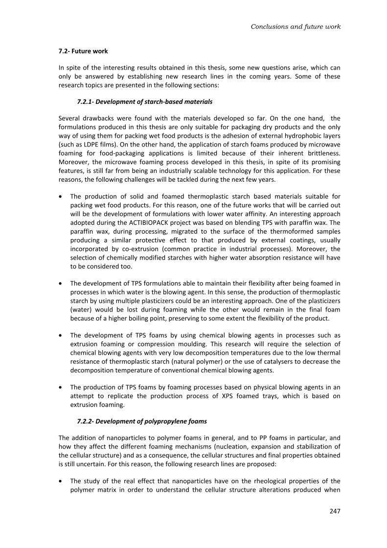
Conclusions and future work
247
7.2- Future work
In spite of the interesting results obtained in this thesis, some new questions arise, which can only be answered by establishing new research lines in the coming years. Some of these research topics are presented in the following sections:
7.2.1- Development of starch-based materials
Several drawbacks were found with the materials developed so far. On the one hand, the formulations produced in this thesis are only suitable for packaging dry products and the only way of using them for packing wet food products is the adhesion of external hydrophobic layers (such as LDPE films). On the other hand, the application of starch foams produced by microwave foaming for food-packaging applications is limited because of their inherent brittleness. Moreover, the microwave foaming process developed in this thesis, in spite of its promising features, is still far from being an industrially scalable technology for this application. For these reasons, the following challenges will be tackled during the next few years.
The production of solid and foamed thermoplastic starch based materials suitable for packing wet food products. For this reason, one of the future works that will be carried out will be the development of formulations with lower water affinity. An interesting approach adopted during the ACTIBIOPACK project was based on blending TPS with paraffin wax. The paraffin wax, during processing, migrated to the surface of the thermoformed samples producing a similar protective effect to that produced by external coatings, usually incorporated by co-extrusion (common practice in industrial processes). Moreover, the selection of chemically modified starches with higher water absorption resistance will have to be considered too.
The development of TPS formulations able to maintain their flexibility after being foamed in processes in which water is the blowing agent. In this sense, the production of thermoplastic starch by using multiple plasticizers could be an interesting approach. One of the plasticizers (water) would be lost during foaming while the other would remain in the final foam because of a higher boiling point, preserving to some extent the flexibility of the product.
The development of TPS foams by using chemical blowing agents in processes such as extrusion foaming or compression moulding. This research will require the selection of chemical blowing agents with very low decomposition temperatures due to the low thermal resistance of thermoplastic starch (natural polymer) or the use of catalysers to decrease the decomposition temperature of conventional chemical blowing agents.
The production of TPS foams by foaming processes based on physical blowing agents in an attempt to replicate the production process of XPS foamed trays, which is based on extrusion foaming.
7.2.2- Development of polypropylene foams
The addition of nanoparticles to polymer foams in general, and to PP foams in particular, and how they affect the different foaming mechanisms (nucleation, expansion and stabilization of the cellular structure) and as a consequence, the cellular structures and final properties obtained is still uncertain. For this reason, the following research lines are proposed:
The study of the real effect that nanoparticles have on the rheological properties of the polymer matrix in order to understand the cellular structure alterations produced when

Chapter 7
248
foaming nanoreinforced polypropylenes. In this sense, extensional viscosity and shear rheology measurements of pure and nanoreinforced formulations will be very helpful.
To evaluate in more detail the heterogeneous nucleating effect that nanoparticles have on polymer foams produced under the effect of external pressures, such as in the ICM foaming route. Ex-situ and in-situ analysis of the foaming process based on X-ray radioscopy could be used for this purpose.
To obtain further understanding of the mechanical response of anisotropic foams reinforced with nanoparticles, analysing the deformation mechanisms and improving the theoretical models.
To use the ICM route to produce foams based on thermoplastic materials with higher stiffness and strength than PP.
Moreover, a full implementation of these rigid foams in the market of structural foamed panels still requires further research in certain areas.
The chemical modification of the PP foams surface by grafting reactions (for instance) could be an interesting strategy in order to increase their adhesion capability to solid skins based on epoxy resins composites, which is, in principle, low due to the chemical nature of PP.
Further development of the formulations and of the self-expandable moulds employed in the ICM process for the production of lower density foams (ρ≤90 kg/m3) and with homogeneous cellular structures. For instance, the large thickness of the moulds currently employed avoids high cooling rates and as a result, the cellular structures are more prone to degeneration.
The adaptation of the concept underlying the ICM route to foaming processes such as injection moulding, which can increase significantly the process output. This would allow PP foams competing with other rigid foams with lower mechanical performance but produced by more cost-effective processes such as extrusion foaming (PET foams).

ANNEX:
ANICELL PATENT: Method for producing cellular materials
having a thermoplastic matrix


ANNE
EX: ANICELL patent

Anne
A.2
ex

Anicell PPatent
A.3

Anne
A.4
ex
Anicell PPatent
A.5

Anne
A.6
ex

Anicell PPatent
A.7

Anne
A.8
ex

Anicell PPatent
A.9

Anne
A.10
ex

Anicell PPatent
A.11

Anne
A.12
ex

Anicell PPatent
A.13

Anne
A.14
ex

Anicell PPatent
A.15

Anne
A.16
ex
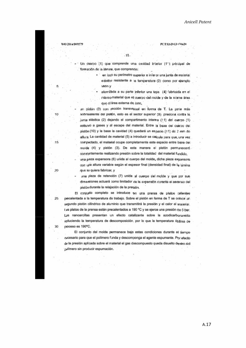
Anicell PPatent
A.17

Anne
A.18
ex

Anicell PPatent
A.19

Anne
A.20
ex

Anicell PPatent
A.21

Anne
A.22
ex

Anicell PPatent
A.23

Anne
A.24
ex

Anicell PPatent
A.25

Anne
A.26
ex

Anicell PPatent
A.27