teledyne brown engineering, s/n ee001tb-ee0042tb, nsn …
TRANSCRIPT
FINAL REPORT FEBRUARY 1998
REPORT NO. 97-03
SINGLE ROUND CONTAINER (LARGE) (SRCXX) PRODUCED BY
TELEDYNE BROWN ENGINEERING, S/N EE001TB-EE0042TB,
NSN 8140-01-375-7070, CERTIFICATION TESTS
Reproduced From Best Available Copy
DISTRIBUTION STATEMENT A Approved for Public Release
Distribution Unlimited
Prepared for: Project Manager for Nonstockpile
Chemical Materiel ATTN: SFAE-CD-NM Aberdeen Proving Ground, MD 21010-5401
Distribution Unlimited
VALIDATION ENGINEERING DIVISION SAVANNA, ILLINOIS 61074-9639 SAVANNA, ILLINOIS
20010227 057

A V ATT, ABTUTY NOTICE
A copy of this report will be furnished each attendee on automatic distribution. Additional
copies or authority for reprinting may be obtained by written request from Director, U.S. Army
Defense Ammunition Center, ATTN: SIOAC-DEV, 3700 Army Depot Road, Savanna, IL
61074-9639.
DISTRIBUTION INSTRUCTIONS
Destroy this report when no longer needed. Do not return.
***
Citation of trade names in this report does not constitute an official endorsement.
***
The information contained herein will not be used for advertising purposes.

UNCLASSIFIED SECURITY CLASSIFICATION OF THIS PAGE
REPORT DOCUMENTATION PAGE Form Approved OMB No. 0704-0188
1a. REPORT SECURITY CLASSIFICATION
UNCLASSIFIED 1b. RESTRICTIVE MARKINGS
2a. SECURITY CLASSIFICATION AUTHORITY 3. DISTRIBUTION /AVAILABILITY OF REPORT
2b. DECLASSIFICATION / DOWNGRADING SCHEDULE UNLIMITED
4. PERFORMING ORGANIZATION REPORT NUMBER(S)
97-03
5. MONITORING ORGANIZATION REPORT NUMBER(S)
6a. NAME OF PERFORMING ORGANIZATION
U.S. Army Defense Ammunition Center
6b. OFFICE SYMBOL (if applicable)
SIOAC-DEV
7a. NAME OF MONITORING ORGANIZATION
6c. ADDRESS (City, State, and ZIP Code)
ATTN: SIOAC-DEV Savanna, IL 61074-9639
7b. ADDRESS (City, State, and ZIP Code)
8a. NAME OF FUNDING/SPONSORING ORGANIZATION Project Manager for Nonstockpile Chemical Materiel
8b. OFFICE SYMBOL (if applicable)
SFAE-CD-NM
9. PROCUREMENT INSTRUMENT IDENTIFICATION NUMBER
8c. ADDRESS (City, State, and ZIP Code)
ATTN: SFAE-CD-NM Aberdeen Proving Ground, MD 21010-5401
10. SOURCE OF FUNDING NUMBERS PROGRAM ELEMENT NO.
PROJECT NO. TASK NO. WORK UNIT ACCESSION NO.
11. TITLE (Include Security Classification) Single Round Container (Large) (SRCXX) Produced by Teledyne Brown Engineering, S/N EE001TB-EE0042TB, NSN 8140-01-375-7070, Certification Tests
12. PERSONAL AUTHOR(S)
William R. Meyer
13a. TYPE OF REPORT Final
13b. TIME COVERED
FROM TO
14. DATE OF REPORT (Year, Month, Day)
1998 February 15. PAGE COUNT
16. SUPPLEMENTARY NOTATION
17. COSATI CODES FIELD GROUP SUB-GROUP
18. SUBJECT TERMS (Continue on reverse if necessary and identify by block number)
19. ABSTRACT (Continue on reverse if necessary and identify by block number)
The U.S. Army Defense Ammunition Center (DAC), Validation Engineering Division (SIOAC-DEV), was tasked by the Project Manager for Nonstockpile Chemical Materiel (PMNSCM) to conduct First Article Testing (FAT) on the Single Round Container (Large) (SRCXX) chemical overpack container that was manufactured by Teledyne Brown Engineering. These tests were conducted to determine if the SRCXX could meet the test requirements set forth in the DAC Nonstockpile Test Plan for SRCX, SRCXX, MRC-RRS, MRC-7 X 27, MRC-9 X 41, MRC-12 X 56, MRC-21 X 79, and MRC-16.5 X 5.5 dated April 1997. As tested the SRCXX meets and exceeds all test requirements spelled out in the test plan mentioned above.
20. DISTRIBUTION / AVAILABILITY OF ABSTRACT
UNCLASSIFIED/UNLIMITED SAME AS RPT. □
DTIC USERS
21. ABSTRACT SECURITY CLASSIFICATION
UNCLASSIFIED 22a. NAME OF RESPONSIBLE INDIVIDUAL
JEROME H. KROHN 22b. TELEPHONE (Include Area Code)
■ 815-273-8929 22c. OFFICE SYMBOL
SIOAC-DEV
DD Form 1473, Jun 86 Previous editions are obsolete SECURITY CLASSIFICATION OF THIS PAGE
UNCLASSIFIED

U.S. ARMY DEFENSE AMMUNITION CENTER
VALIDATION ENGINEERING DIVISION
SAVANNA, IL 61074-9639
REPORT NO. 97-03
SINGLE ROUND CONTAINER (LARGE) (SRCXX) PRODUCED BY TELEDYNE BROWN
ENGINEERING, S/N EE001TB-EE0042TB, NSN 8140-01-375-7070,
CERTIFICATION TESTS
TABLE OF CONTENTS
PART PAGE NO.
1. INTRODUCTION -1
A. BACKGROUND 1-1
B. AUTHORITY
C. OBJECTIVE
D. CONCLUSION
2. ATTENDEES 2-1
3. ITEM TESTED 3-1
4. TEST EQUIPMENT 4-1
5. TEST SEQUENCE 5-1
6. TEST PROCEDURES 6-1
7. TEST RESULTS 7-1
8. UN POP TESTS (STANDARD FORM) 8-1

PART PAGE NO.
9. SPECIAL PACKAGING INSTRUCTIONS (SPI) 9-1
10. PHOTOGRAPHS 10-1
11. GRAPHS 11-1
12. DRAWINGS 12-1
13. APPENDIX 13-1
ui

PARTI
INTRODUCTION
A. BACKGROUND The U.S. Army Defense Ammunition Center (DAC), Validation
Engineering Division (SIOAC-DEV), was tasked by Project Manager for Nonstockpile Chemical
Materiel (PMNSCM) to conduct First Article Testing (FAT) on the Single Round Container
(Large) (SRCXX) chemical overpack container that was manufactured by Teledyne Brown
Engineering. These containers were manufactured under contract DAAA09-95-D-001, with
serial numbers EE0001TB to EE0042TB. These tests were conducted to determine if the
SRCXX could meet the test requirements set forth in the DAC Nonstockpile Test Plan for
SRCX, SRCXX, MRC-RRS, MRC-7 X 27, MRC-9 X 41, MRC-12 X 56, MRC-21 X 79, and
MRC-16.5 X 5.5 (dated April 1997).
This test plan was approved by the Chemical Container Approval Authority and was designed to
demonstrate the SRCXX meets the performance criteria set forth by the Chemical Container
Process Action Team (CCPAT). The SRCXX is intended for transport and storage of chemical
munitions in the public domain and is restricted to military air and ground transportation. This
container is used to support PMNSCM mission of recovery and containment of chemical warfare
materials (CWM).
B. AUTHORITY. These tests were conducted IAW mission responsibilities delegated by the
U.S. Army Armament, Munitions and Chemical Command (AMCCOM), Rock Island, IL.
C. OBJECTIVE. The objective of these tests is to verify that the SRCXX meets United
Nations (UN) Performance Oriented Packaging (POP), Level I; road transportability;
high- and low-frequency vibration; drop test and 40-foot drop test requirements for the transport
and storage of hazardous chemical agents. These tests are described in the DAC Nonstockpile
1-1

MRC Test Plan for SRCX, SRCXX, MRC-RRS, MRC-7 X 27, MRC-9 X 41, MRC-12 X 56,
MRC-21 X 79, and MRC-16.5 X 5.5 (dated April 1997).
The objective of these tests is also to provide data to support the Chemical Container Approval
of the SRCXX for U.S. Army (USA) use.
D. CONCLUSION. As tested, the SRCXX meets and exceeds all test requirements spelled out
in the DAC Nonstockpile MRC Test Plan for SRCX, SRCXX, MRC-RRS, MRC-7 X 27,
MRC-9 X 41, MRC-12 X 56, MRC-21 X 79, AND MRC-16.5 X 5.5 (dated April 1997).
1-2

PART 2
JANUARY 1998
ATTENDEES
William R. Meyer Director
General Engineer U.S. Army Defense Ammunition Center
DSN 585-8090 ATTN: SIOAC-DEV
815-273-8090 3700 Army Depot Road
Savanna, IL 61074-9639
Bradley J. Haas Director
Mechanical Engineer U.S. Army Defense Ammunition Center
DSN 585-8336 ATTN: SIOAC-DEV
815-273-8336 3700 Army Depot Road
Savanna, JE 61074-9639
Jerome H. Krohn Director
Supervisory Engineer U.S. Army Defense Ammunition Center
DSN 585-8908 ATTN: SIOAC-DEV
815-273-8908 3700 Army Depot Road
Savanna, EL 61074-9639
Thomas J. Michels Director
Supervisory Engineer U.S. Army Defense Ammunition Center
DSN 585-8080 ATTN: SIOAC-DES
815-273-8080 3700 Army Depot Road Savanna, IL 61074-9639
Nino L. Bonavito Director
Mechanical Engineer U.S. Army Defense Ammunition Center
DSN 585-8085 ATTN: SIOAC-DES
815-273-8085 3700 Army Depot Road
Savanna, IL 61074-9639
Don Brooke , Commander
QASAS U.S. Army Chemical and Biological Command
DSN 584-3949 ATTN: AMSCB-CMO
Aberdeen Proving Ground, MD 21010-5423
2-1

Trooper Studdert
QASAS DSN 584-7238
Thomas Hoff
Engineer
DSN 584-8738
Steve Bird
Project Scientist
DSN 584-4577
Commander
U.S. Army Chemical and Biological Command
ATTN: AMSCB-SO Aberdeen Proving Ground, MD 21010-5423
Project Manager for Non-Stockpile
Chemical Materiel
ATTN: SFAE-CD-NM
Aberdeen Proving Ground, MD 21010-4501
Project Manager for Non-Stockpile
Chemical Materiel
ATTN: SFAE-CD-NM
Aberdeen Proving Ground, MD 21010-4501
2-2

PART 3
TTEM TESTED
Item Name
Material
Coating
Drawing number
Manufacturer
Year of Manufacture
Container Exterior Length
Container Exterior Diameter
Container Interior Length
Container Interior Diameter
Flange Diameter
Flange Thickness
Number of Bolts
Bolt Size
Bolt Grade
Seal Type
Seal Diameter
Seal Thickness
Seal Material
Container Weight Empty
Container Weight Loaded
Container Shipping Box
Container Shipping Box Length (Exterior)
SRCXX
Cold Drawn Steel
Care Paint (Green)
15-12-42 to 15-12-48,15-12-511
Teledyne Brown Engineering
1996
52.25 inches
12.0 inches
52.25 inches
11.75 inches
15.0 inches
1.0 inches
10
0.500 X 20 UNF-2B
Grade 8, NSN 5305-01-396-0996
O-Ring
12.47 inches +/-.06 inches
0.275 inches +/-.06 inches
Butyl Rubber
135 pounds
340 pounds
3/8-inch Plywood
54 inches
3-1

Container Shipping Box Width (Exterior)
Container Shipping Box Height (Exterior)
Container Shipping Box Weight
15-7.8 inches
15-7/8 inches
70 pounds
Total Test Weight (Container and Shipping Box) 410 pounds
3-2

PART 4
TEST EQUIPMENT
A. Helium Leak Test
1. Manufacturer
2. Model Number
3. Test Method
Leybold Heraeus
UL-100
ASTME499-73
Title 49 CFR, Section 178.604
B. Compression Test
1. Manufacturer
2. Model Number
3. Test Method
Ormond Inc.
TOAFT 266 (5 OK)
Title 49 CFR Section 178.606
C. Low Frequency Vibration Test
1. Manufacturer
2. Model Number
3. Test Method
Gaynes Engineering
G-6000
Title 49 CFR, Section 178.608
MIL-STD 810E, Method 514.4
4. Manufacturer
5. Model Number
6. Test Method
Gaynes Engineering
G-4000
Title 49 CFR Section 178.608
MIL-STD 810E, Method 514.4
D. High Frequency Vibration Test
1. Manufacturer
2. Model Number
3. Test Method
4. Tests Conducted By
Ling Engineering
PP 20/35
MEL-STD 810E, Method 514.4
Datasyst, Delafield, WI
4-1

E. Hydrostatic Test
1. Manufacturer Rice Mfg. Inc.
2. Model Number H-1500
3. Test Method Title 49 CFR, Section 178.605
F. Drop Test
1. Manufacturer Eastern Rotorcraft Corp.
2. Model Number AWE-49
3. Quick Release Type Helicopter Cargo Release
4. Test Method Title 49 CFR, Section 178.603
G. Transportability Test
1. Manufacturer GMC
2. Type 1.25 ton
3. Nomenclature CUCV Cargo Truck
4. Test Method Defense Ammunition Center, TP-94-1
H. Environmental Chamber
1. Manufacturer Webber Mfg. Inc.
2. Model Number F125-75 + M5X
3. Controller Micristar
4. Model Number 828-D00-403-000-120-00
I. Data Recorder
1. Manufacturer Omni data
2. Type Polycorder
3. Model Number 700
J. Pressure Transducer
1. Manufacturer Omega
2. Model Number PX236-060GV
4-2

PART 5
TEST SEQUENCE
Test Conducted
A. Helium-Leak Test
B. Road Transportability Tests
1. Pass 1 over hazard course
2. Pass 2 over hazard course
3. 30-mile road hazard course
4. Pass 3 over hazard course
5. Pass 4 over hazard course
6. Panic stop at 5 mph
7. Panic stop at 10 mph
8. Panic stop at 15 mph
9. Panic stop at 5 mph in reverse
10. Washboard Course
C. Helium-Leak Test
D. UN POP Stacking Test
E. Helium-Leak Test
F. UN POP Vibration Test
G. Helium-Leak Test
H. UN POP Hydrostatic Test
I. Helium-Leak Test
J. UN POP Longitudinal Drop Test 1
K. Helium-Leak Test
L. UN POP Longitudinal Drop Test 2
M. Helium-Leak Test
Test Method
ASTM E-499-73, Method B
DAC TP-94-1
DAC TP-94-1, Page 3-2
DAC TP-94-1, Page 3-2
DAC TP-94-1, Page 3-3
DAC TP-94-1, Page 3-2
DAC TP-94-1, Page 3-2
DAC TP-94-1, Page 3-3
DAC TP-94-1, Page 3-3
DAC TP-94-1, Page 3-3
DAC TP-94-1, Page 3-3
DAC TP-94-1, Page 3-4
ASTM E-499-73, Method B
Title 49 CFR, Section 178.606
ASTM E-499-73, Method B
Title 49 CFR, Section 178.608
ASTM E-499-73, Method B
Title 49 CFR, Section 178.605
ASTM E-499-73, Method B
Title 49 CFR, Section 178.603
ASTM E-499-73, Method B
Title 49 CFR, Section 178.603
ASTM E-499-73, Method B
5-1

Test Conducted
N. UN POP Longitudinal Drop Test 3
O. Helium-Leak Test
P. UN POP 45 Degree Drop Test 1
Q. Helium-Leak Test
R. UN POP 45 Degree Drop Test 2
S. Helium-Leak Test
T. UN POP 45 Degree Drop Test 3
U. Helium-Leak Test
V. High-Frequency Vibration Test
1. Pre-condition to -35 degrees Fahrenheit
2. Helicopter Vibration 4 hrs longitudinal
3. Aircraft vibration 1 hr longitudinal
4. Precondition to 160 degrees Fahrenheit
5. Helicopter vibration 4 hrs. Longitudinal
6. Aircraft vibration 1 hr. Longitudinal
7. Pre-condition to -35 degrees Fahrenheit
8. Helicopter vibration 4 hours lateral direction
9. Aircraft vibration 1 hour lateral direction
10. Pre-condition to 160 degrees Fahrenheit
11. Helicopter vibration 4 hours lateral direction
12. Aircraft vibration 1 hour lateral dirction
W. Helium-Leak Test
X. Low-Frequency Vibration Test
1. Pre-condition to -35 degrees Fahrenheit
2. 20-minute vibration test vertical direction
3. Helium-leak test
Test Method
Title 49 CFR, Section 178.603
ASTM E-499-73, Method B
Title 49 CFR, Section 178.603
ASTM E-499-73, Method B
Title 49 CFR, Section 178.603
ASTM E-499-73, Method B
Title 49 CFR, Section 178.603
ASTM E-499-73, Method B
MEL-STD810E, Method 514.4 .
MTL-STD 810E, Method 514.4, Category 6
MDL-STD 810E, Method 514.4, Category 4
MIL-STD 810E, Method 514.4, Category 4
MIL-STD 810E, Method 514.4, Category 6
MIL-STD 810E, Method 514.4, Category 4
MTL-STD810E, Method 514.4, Category 6
MDL-STD 810E, Method 514.4, Category 4
MIL-STD 810E, Method 514.4, Categroy 6
ASTM E-499-73, Method B
MIL-STD 810E, Method 514.4
MIL-STD 810E, Method 514.4, Category 3
ASTM E-499-73, Method B
5-2

Test Conducted
4. Pre-condition to 160 degrees Fahrenheit
5. 20-minute vibration test vertical direction
Y. Helium-Leak Test
Z. Drop Test
1. Precondition to -35 degrees Fahrenheit
2. 45 degree drop test
3. Helium-leak test
4. Pre-condition to 160 degrees Fahrenheit
5. 45 degree drop test
AA. Helium-Leak Test
BB. 40-Foot Drop Test
CC. Helium Leak Test
Test Method
MJL-STD 810E, Method 514.4, Category 3
ASTM E499-73, Method B
Title 49 CFR, Section 178.603 (Note 1)
ASTM E499-73, Method B
Title 49 CFR, Section 178.603 (Note 1)
ASTM E499-73, Method B
ARRADOM Drawing Number 883737
ASTM E499-73, Method B
Note 1 Same drop orientation as specified in UN POP requirements, with extreme temperature (-35 degrees Fahrenheit and 160 degrees Fahrenheit) added to verify leak integrity after a drop to the weakest area on the container.
5-3

PART 6
TEST PROCEDURES
GENERAL DESCRIPTION AND TEST SEQUENCE
Following is an overview of tests that have been conducted on the SRCXX. The sequence
of tests was from the least to the most destructive to minimize the number of test samples
required to complete testing. The intent of the overall test program is to simulate all anticipated
modes of transportation and temperatures at which these containers are expected to be
serviceable during their life cycle. The requirements set forth herein exceed test requirements
established in Title 49 CFR for the shipment of hazardous materials. The containers tested were
randomly selected from a lot of 60 containers, with serial nos. EE001TB, EE0010TB, and
EE0028TB being tested.
6-1

CONTAINER TESTING
6-2

TRANSPORTABILITY TESTS
6-3

TRANSPORTABILITY TESTS.
FAT samples will be subjected to transportability tests in the following sequence: road
hazard course, 30-mile road trip, road hazard course, washboard course, and panic stops IAW
DAC Test Plan, TP-94-01. These tests will be conducted at ambient temperature with a standard
military vehicle(s). Rail impact and shipboard simulation tests will not be conducted on FAT
samples, these are not anticipated modes of transportation for these containers.
1. Road Hazard Course. This step provides for the specimen load to be driven over a
200-foot-long segment of concrete-paved road which consists of two series of railroad ties
projecting 6 inches above the level of the road surface. This hazard course was traversed two
times (see Figure 1).
(a) The first series of ties are spaced on 8-foot centers and alternately positioned
on opposite sides of the road centerline for a distance of 50 feet.
(b) Following the first series of ties, a paved roadway of 75 feet separates the
first and second series of railroad ties.
(c) The second series of ties is alternately positioned similarly to the first, but
spaced on 10-foot centers for a distance of 50 feet.
(d) The test load is driven across the road hazard course at speeds that would
produce the most violent vertical and side-to-side rolling reaction obtainable in traversing the
road hazard course (approximately 5 mph).
6-4

\
- TIE HOLDER ASSEMBLY 5' I EAN K
1
/ 7 7'X 9" TIE, 6'-0 LONG—'
\ K
CONCRETE - SURFACE
/ X. ™™r
TIE HOLDER DETAILS FlLrUK
2. Road Trip. Using a suitable truck/tractor and trailer, or tactical vehicle, the tactical
vehicle/specimen load is driven/towed for a total distance of at least 30 miles over a combination
of roads surfaced with gravel, concrete, or asphalt. Test route included curves, corners, railroad
crossings, cattle guards, and stops and starts. The test vehicle travels at the maximum speed
suitable for the particular road being traversed, except as limited by legal restrictions. This step
provides for the tactical vehicle/specimen load to be subjected to three full airbrake stops while
traveling in the forward direction and one in the reverse direction while traveling down a
7 degree grade. The first three stops are at 5, 10, and 15 mph, while the stop in the reverse
direction is approximately 5 mph.
6-5

3. Road Hazard Course. The first step in the road transportability testing is fully repeated.
4. Washboard Course. Using a suitable truck/tractor, and/or tactical vehicle, the specimen
is towed/driven over the washboard course at a speed which produces the most violent response
in the particular test load (as indicated by the resonant frequency of the suspension system
beneath the load). The washboard course is constructed as shown in Figure 2.
TYPICAL SECTION
FIGURE 2
6-6

UN POP TESTS
6-7

TIN PERFORMANCE ORTENTEO PACKAGING TESTS.
Subpart M
TESTING OF NON-BULK PACKAGINGS AND PACKAGES
Sec. 178.600 Purpose and scope.
This subpart prescribes certain testing requirements for performance-oriented packagings
identified in Subpart L of this part.
Sec. 178.601 General requirements.
(a) General. The test procedures prescribed in this subpart are intended to ensure that packages
containing hazardous materials can withstand normal conditions of transportation and are
considered minimum requirements. Each packaging must be manufactured and assembled so as
to be capable of successfully passing the prescribed tests and of conforming to the requirements
of § 173.24 of this subchapter at all times while in transportation.
(b) Responsibility. It is the responsibility of the packaging manufacturer and the person who
offers a hazardous material for transportation, to the extent that assembly functions including
final closure are performed by the latter to assure that each package is capable of passing the
prescribed tests.
(c) Definitions. For the purpose of this subpart:
(1) Design qualification testing is the performance of the drop, leakproofness, hydrostatic
pressure, stacking, and cooperage tests, as applicable, prescribed in §§ 178.603, 178.604,
178.605, 178.606, or 178.607, respectively, for each new or different packaging, at the start of
production ofthat packaging.

^)S!^ä
(2) Periodic retesting is the performance of the drop, leakproofness, hydrostatic pressure, and
stacking tests, as applicable, prescribed in §§ 178.603, 178.604, 178.605, or 178.606,
respectively, at the frequency specified in 178.601(e) of this subpart.
(3) Production testing is the performance of the leakproofness test prescribed in § 178.604 of
this subpart on each single or composite packaging intended to contain a liquid.
(4) A different packaging is one that differs (i.e. is not identical) from a previously produced
packaging in structural design, size, material of construction, wall thickness or manner of
construction but does not include:
(i) A packaging which differs only in surface treatment;
(ii) A combination packaging which differs only in that the outer packaging has been
successfully tested with different inner packagings. A variety of such inner packagings
may be assembled in this outer packaging without further testing;
(iii) A plastic packaging which differs only with regard to additives which conform to
§§ 178.509(b)(4) or (5) of this part;
(iv) A combination packaging with inner packagings conforming to the provisions of
paragraph (g) of this section; or
(v) Packagings which differ from the design type only in their lesser design height.
(d) Design qualification testing. The packaging manufacturer shall achieve successful test
results for the design qualification testing at the start of production of each new or different
packaging.
6-9

(e) Periodic retesting. The packaging manufacturer shall achieve successful test results for the
periodic retesting at intervals established by the manufacturer of sufficient frequency to ensure
that each packaging produced by the manufacturer is capable of passing the design qualification
tests. Changes in retest frequency are subject to the approval of the Associate Administrator for
Hazardous Materials Safety. For single or composite packagings, the periodic retests must be
conducted at least once every 12 months. For combination packagings, the periodic retests must
be conducted at least once every 24 months.
(f) Test samples. The manufacturer shall conduct the design qualification and periodic tests
prescribed in this subpart using random samples of packagings, in the numbers specified in the
appropriate test section. In addition, the leakproofness test, when required, shall be performed
on each packaging produced by the manufacturer, and each packaging prior to reuse under
§ 173.28 of this subchapter, by the reconditioner.
(g) Selective testing. The selective testing of packagings that differ only in minor respects from
a tested type is permitted as described in this section. For air transport, packagings must comply
with § 173.27(c)(1) and (c)(2) of this subchapter.
(1) Selective testing of combination packagings, Variation 1. Variations are permitted in
inner packagings of a tested combination package, without further testing of the package,
provided an equivalent level of performance is maintained, as follows:
(i) Inner packagings of equivalent or smaller size may be used provided -
(A) The inner packagings are of similar design to the tested inner packagings
(i.e. shape - round, rectangular, etc.);
6-10

ISS*
(B) The material of construction of the inner packagings (glass, plastic, metal, etc.)
offers resistance to impact and stacking forces equal to or greater than that of the
originally tested inner packaging;
(C) The inner packagings have the same or smaller openings and the closure is of
similar design (e.g., screw cap, friction lid, etc.);
(D) Sufficient additional cushioning material is used to take up void spaces and to
prevent significant movement of the inner packagings;
(E) Inner packagings are oriented with the outer packing in the same manner as in the
tested package; and,
(F) The gross mass of the package does not exceed that originally tested.
(ii) A lesser number of the tested inner packagings, or of the alternative types of inner
packagings identified in paragraph (g)(l)(i) of this section, may be used provided
sufficient cushioning is added to fill void space(s) and to prevent significant movement
of the inner packagings.
(2) Selective testing of combination packagings, Variation 2. Inner packagings of any type,
for solids or liquids, may be assembled and transported without testing in an outer packaging
under the following conditions.
(i) The outer packaging must have been successfully tested in accordance with § 178.603
of this subpart, with fragile (e.g., glass) inner packagings at the Packing Group 1 drop
height;
6-11
(ii) The total combined gross mass of inner packagings may not exceed one-half the gross
mass of inner packagings used for the drop test;
(iii) The thickness of cushioning material between inner packagings and between inner
packagings and the outside of the packaging may not be reduced below the
corresponding thickness in the originally tested packaging; and when a single inner
packaging was used in the original test, the thickness of cushioning between inner
packagings may not be less than the thickness of cushioning between the outside of the
packaging and the inner packaging in the original test. When either fewer or smaller inner
packagings are used (as compared to the inner packagings used in the drop test),
sufficient additional cushioning material must be used to take up void spaces.
(iv) The outer packaging must have successfully passed the stacking test set forth in
§ 178.606 of this subpart when empty, i.e., without either inner packagings or
cushioning materials. The total mass of identical packages must be based on the
combined mass of inner packagings used for the drop test;
(v) Inner packagings containing liquids must be completely surrounded with a sufficient
quantity of absorbent material to absorb the entire liquid contents of the inner
packagings;
(vi) When the outer packaging is intended to contain inner packagings for liquids and is not
leakproof, or is intended to contain inner packagings for solids and is not sift-proof, a
means of containing any liquid or solid contents in the event of leakage must be
provided in the form of a leakproof liner, plastic bag, or other equally efficient means
of containment; and
6-12

(vii) Packagings must be marked in accordance with 178.503 of this part as having been
tested to Packing Group 1 performance for combination packagings. The marked
maximum gross mass may not exceed the sum of the mass of the outer packaging plus
one-half the mass of the filled inner packagings of the tested combination packaging. In
addition, the marking required by 178.503(a)(2) of this part must include the letter "V."
(3) Variation 3. Packagings other than combination packagings which are produced with
reductions in external dimensions (i.e., length, width or diameter) of up to 25 percent of the
dimensions of a tested packaging may be used without further testing provided an equivalent
level of performance is maintained. The packagings must, in all other respects (including wall
thicknesses), be identical to the tested design-type. The marked gross mass (when required) must
be reduced in proportion to the reduction in volume.
(4) Variation 4. Variations are permitted in outer packagings of a tested design-type
combination packaging, without further testing, provided an equivalent level of performance is
maintained, as follows:
(i) Each external dimension (length, width and height) is less than or equal to the
corresponding dimension of the tested design-type;
(ii) The structural design of the tested outer packaging (i.e. methods of construction,
materials of construction, strength characteristics of materials of construction, method of
closure and material thicknesses) is maintained;
(iii) The inner packagings are identical to the inner packagings used in the tested design
type except that their size and mass may be less; and they are oriented within the outer
packaging in the same manner as in the tested packaging;
6-13

(iv) The same type or design of absorbent materials, cushioning materials and any other
components necessary to contain and protect inner packagings, as used in the tested
design type, are maintained. The thickness of cushioning material between inner
packagings and between inner packagings and the outside of the packaging may not be
less than the thickness in the tested design type packaging; and
(v) Sufficient additional cushioning material is used to take up void spaces and to prevent
significant movement of the inner packagings. An outer packaging qualifying for use in
transport in accordance with all of the above conditions may also be used without testing
to transport inner packagings substituted for the originally tested inner packagings in
accordance with the conditions set out in Variation 1 in paragraph (g)(1) of this section.
(5) Variation 5. Single packagings (i.e., non-bulk packagings other than combination
packaging(s), that differ from a tested design type only to the extent that the closure device or
gasketing differs from that used in the originally tested design type, may be used without further
testing, provided an equivalent level of performance is maintained, subject to the following
conditions (the qualifying tests):
(i) A packaging with the replacement closure devices or gasketing must successfully pass
the drop test specified in § 178.602 in the orientation which most severely tests the
integrity of the closure or gasket;
(ii) When intended to contain liquids, a packaging with the replacement closure devices or
gasketing must successfully pass the leakproofness test specified in § 178.603, the
hydrostatic pressure test specified in § 178.605, and the stacking test specified in
178.606. Replacement closures and gasketings qualified under the above test
requirements are authorized without additional testing for packagings described in
paragraph (g)(3) of this section. Replacement closures and gasketings qualified under the
6-14

above test requirements also are authorized without additional testing for different tested
design packagings of the same type as the originally tested packaging, provided the
original design type tests are more severe or comparable to tests which would otherwise be
conducted on the packaging with the replacement closures or gasketings. (For example:
The packaging used in the qualifying tests has a lesser packaging wall thickness than the
packaging with replacement closure devices or gasketing; the gross mass of the packaging
used in the qualifying drop test equals or exceeds the mass for which the packaging with
replacement closure devices or gasketing was tested; the packaging used in the qualifying
drop test was dropped from the same or greater height than the height from which the
packaging with replacement closure devices or gasketing was dropped in design type tests;
and the specific gravity of the substance used in the qualifying drop test was the same or
greater than the specific gravity of the liquid used in the design type tests of the packaging
with replacement closure devices or gasketing.)
(6) The provisions in Variations 1, 2, and 4 in paragraphs (g)(1), (2), and (4) of this section for
combination packagings may be applied to packagings containing articles, where the provisions
for inner packagings are applied analogously to the articles. In this case, inner packagings need
not comply with § 173.27(c)(1) and (c)(2) of this subchapter.
(7) Approval of selective testing. In addition to the provisions of § 178.601(g)(2) of this
subpart, the Associate Administrator for Hazardous Materials Safety may approve the selective
testing of packagings that differ only in minor respects from a tested type.
(h) Approval of equivalent packagings. A packaging having specifications different from
those in §§ 178.505-178.523 of this part, or which is tested using methods or test intervals other
than those specified in Subpart M of this Part, may be used if approved by the Associate
Administrator for Hazardous Materials Safety. Such packagings must be shown to be equally
effective, and testing methods used must be equivalent.
6-15

(i) Proof of compliance. Notwithstanding the periodic retest intervals specified in paragraph
(e) of this section, the Associate Administrator for Hazardous Materials Safety may at any time
require demonstration of compliance by a manufacturer, through testing in accordance with this
subpart, that packagings meet the requirements of this subpart. As required by the Associate
Administrator for Hazardous Materials Safety, the manufacturer shall either-
(1) Conduct performance tests, or have tests conducted by an independent testing facility, in
accordance with this subpart; or
(2) Supply packagings, in quantities sufficient to conduct tests in accordance with this subpart,
to the Associate Administrator for Hazardous Materials Safety or a designated representative of
the Associate Administrator.
(j) Coatings. If an inner treatment or coating of a packaging is required for safety reasons, the
manufacturer shall design the packaging so that the treatment or coating retains its protective
properties even after withstanding the tests prescribed by this subpart.
(k) Record retention. The person who certifies the tested design type shall-
(1) Keep records of design qualification tests, including specific types, dates, locations,
packaging specifications, test specifics (drop heights, hydrostatic pressures, etc.), results, and test
operators' names or name of person responsible for testing, for each packaging at each location
where that packaging is manufactured and at each location where design qualification tests are
conducted, as long as the packaging is produced and for at least two years thereafter.
(2) Keep records of periodic retests, including specific types, dates, locations, packaging
specifications, test specifics (drop heights, hydrostatic pressures, etc.), results, and test operator's
names or name of person responsible for testing, at each location where that packaging is
6-16

manufactured and at each location where periodic tests are conducted, until such tests are
successfully performed again and for at least two years from the date of each test; and
(3) Make all records of design qualification tests and periodic retests available for inspection by
a representative of the Department of Transportation upon request.
Sec. 178.602 Preparation of packagings and packages for testing.
(a) Except as otherwise provided in this subchapter, each packaging and package must be
closed in preparation for testing and tests must be carried out in the same manner as if prepared
for transportation, including inner packagings in the case of combination packagings.
(b) For the drop and stacking test, inner and single-unit receptacles must be filled to not less
than 95 percent of maximum capacity (see § 171.8 of this subchapter) in the case of solids and
not less than 98 percent maximum capacity in the case of liquids. The material to be transported
in the packagings may be replaced by a non-hazardous material, except for chemical
compatibility testing or where this would invalidate the results of the tests.
(c) If the material to be transported is replaced for test purposes by non-hazardous material, the
material used must be of the same or higher specific gravity as the material to be carried, and its
other physical properties (grain, size, viscosity) which might influence the results of the required
tests must correspond as closely as possible to those of the hazardous material to be transported.
Water may also be used for the liquid drop test under the conditions specified in
§ 178.603(d)(2) of this subpart. It is permissible to use additives, such as bags of lead shot, to
achieve the requisite total package mass, so long as they are placed so that the test results are not
affected.
6-17

(d) Paper or fiberboard packagings must be conditioned for at least 24 hours immediately prior
to testing in an atmosphere maintained-
(1) At 50 percent ± 2 percent relative humidity, and at a temperature of
23°C ± 2°C (73°F ± 4°F). Average values should fall within these limits. Short-term fluctuations
and measurement limitations may cause individual measurements to vary by up to ±5 percent
relative humidity without significant impairment of test reproducibility;
(2) At 65 percent ± 2 percent relative humidity, and at a temperature of
20°C + 2°C (68°F + 4°F), or 27°C ± 2°C (81°F + 4°F). Average values should fall within these
limits. Short-term fluctuations and measurement limitations may cause individual measurements
to vary by up to + 5 percent relative humidity without significant impairment of test
reproducibility; or
(3) For testing at periodic intervals only (i.e., other than initial design qualification testing), at
ambient conditions.
(e) Except as otherwise provided, each packaging must be closed in preparation for testing in
the same manner as if repaired for actual shipment. All closures must be installed using proper
techniques and torques.
(f) Bung-type barrels made of natural wood must be left filled with water for at least 24 hours
before the tests.
6-18

Sec. 178.603 Drop Test.
(a) General. The drop test must be conducted for the qualification of all packaging design types
and performed periodically as specified in § 178.601(e). The number of drops required and the
packages' orientations are as follows:
(b) Exceptions. For testing of single or composite packagings constructed of stainless steel,
nickel, or monel at periodic intervals only (i.e., other than design qualification testing), the drop
test may be conducted with two samples, one sample each for the two drop orientations. These
samples may have been previously used for the hydrostatic pressure or stacking test. Exceptions
for the number of steel and aluminum packaging samples used for conducting the drop test are
subject to the approval of the Associate Administrator for Hazardous Materials Safety.
(c) Special preparation of test samples for the drop test Testing of plastic drums, jerricans,
and boxes, composite packagings with inner plastic receptacles, and of combination packagings
with inner plastic receptacles, other than expanded plastic boxes and bags, must be carried out
when the temperature of the test sample and its contents has been reduced to -18°C(0°F) or
lower. Test liquids shall be kept in the liquid state if necessary, by the addition of anti-freeze.
Test samples prepared in this way are not required to be conditioned in accordance with
§ 178.602(d). Packaging No. of tests Drop orientation of samples
Steel drums, Aluminum drums, Metal drums (other than steel or aluminum), Steel jerricans, Plywood drums, Wooden barrels, Fiber drums, Plastic drums and jerricans, Composite packagings which are in the shape of a drum.
Six — (three for each drop).... First drop (using three samples): The package must strike the target diagonally on the chime or, if the packaging has no
chime, on the circumferential seam or an edge.
Second drop (using the other three samples): The package must strike the target on the weakest part not tested by the first drop, for example a closure or, for some cylindrical drums, the
welded longitudinal seam of the drum body.
Boxes of natural wood, Plywood boxes, Reconstituted wood boxes, Fiberboard boxes, Plastic boxes, Steel or aluminum boxes, Composite packagings which are in the shape of a box.
Five — (one for each drop).... First drop: Flat on the bottom (using the first sample). Second drop: Flat on the top (using the second sample). Third drop: Flat on the long side (using the third sample). Fourth drop: Flat on the short side (using the fourth sample). Fifth drop: On a corner (using the fifth sample).
Bags — single-ply with a side seam. Three — (three drops per bag). First drop: Flat on a wide face (using all three samples). Second drop: Flat on a narrow face (using all three samples). Third drop: On an end of the bag (using all three samples).
Bags — single-ply without a side seam, or multi-ply
Three — (three drops per bag). First drop: Flat on a wide face (using all three samples). Second drop: On an end of the bag (using all three samples).
6-19

(d) Target. The target must be a rigid, non-resilient, flat and horizontal surface.
(e) Drop height. Drop heights, measured as the vertical distance from the target to the lowest
point on the package, must be determined as follows:
(1) For solids and liquids, if the test is performed with the solid or liquid to be transported or
with a non-hazardous material having essentially the same physical characteristic, the drop
height must be determined according to packing group, as follows:
(i) Packing Group I: 1.8 m (5.9 feet).
(ii) Packing Group II: 1.2 m (3.9 feet).
(iii) Packing Group III: 0.8 m (2.6 feet).
(2) For liquids, if the test is performed with water-
(i) Where the materials to be carried have a specific gravity not exceeding 1.2, drop height
must be determined according to packing group, as follows:
(A) Packing Group I: 1.8 m (5.9 feet).
(B) Packing Group II: 1.2 m (3.9 feet).
(C) Packing Group III: 0.8 m (2.6 feet).
(ii) Where the materials to be transported have a specific gravity exceeding 1.2, the drop
height must be calculated on the basis of the specific gravity (SG) of the material to be
carried, rounded up to the first decimal, as follows:
(A) Packing Group I: SG x 1.5 m (4.9 feet).
6-20

T" '
(B) Packing Group II: SGx 1.0 m (3.3 feet).
(C) Packing Group III: SGx 0.67 m (2.2 feet).
(f) Criteria for passing the test. A package is considered to successfully pass the drop
tests for each sample tested if-
(1) For receptacles containing liquid, each receptacle does not leak when equilibrium has been
reached between the internal and external pressures;
(2) For removable head drums for solids, the entire contents are retained by an inner packaging
(e.g., a plastic bag) even if the closure on the top head of the drum is no longer sift-proof;
(3) For a bag, neither the outermost ply nor an outer packaging exhibits any damage likely to
adversely affect safety during transport;
(4) For a composite or combination packaging, there is no damage to the outer packaging
likely to adversely affect safety during transport, and there is no leakage of the filling substance
from the inner packaging;
(5) For a drum, jerrican or bag, any discharge from a closure is slight and ceases immediately
after impact with no further leakage; and
(6) No rupture is permitted in packagings for materials in Class 1 which would permit spillage
of loose explosive substances or articles from the outer packaging.
6-21

Sec. 178.604 Leakproofness test.
(a) General. The leakproofness test must be performed with compressed air or other suitable
gases on all packagings intended to contain liquids, except that:
(1) The inner receptacle of a composite packaging may be tested without the outer packaging
provided the test results are not affected; and
(2) This test is not required for inner packagings of combination packagings.
(b) Number of packagings to be tested-
(1) Production testing. All packagings subject to the provisions of this section must be tested
and must pass the leakproofness test;
(i) Before they are first used in transportation; and
(ii) Prior to reuse, when authorized for reuse by § 173.28 of this subchapter.
(2) Design qualification and periodic testing. Three samples of each different packaging must
be tested and must pass the leakproofness test. Exceptions for the number of samples used in
conducting the leakproofness tests are subject to the approval of the Associate Administrator for
Hazardous Materials Safety.
(c) Special preparation-
(1) For design qualification and periodic testing, packagings must be tested with closures in
place. For production testing, packagings need not have their closures in place. Removable heads
need not be installed during production testing.
6-22

(2) For testing with closures in place, vented closures must either be replaced by similar non-
vented closures or the vent must be sealed.
(d) Test method. The packaging must be restrained under water while an internal air pressure
is applied; the method of restraint must not affect the results of the test. The test must-be
conducted for a period of time sufficient to pressurize the interior of the packaging to the
specified air pressure and to determine if there is leakage of air from the packaging. Other
methods, at least equally effective, may be used in accordance with Appendix B of this part.
(e) Pressure applied. An internal air pressure (gauge) must be applied to the packaging as
indicated for the following packaging groups;
(1) Packing Group I: Not less than 30 kPa (4 psi).
(2) Packing Group II: Not less than 20 kPa (3 psi).
(3) Packing Group III: Not less than 20 kPa (3 psi).
(f) Criteria for passing the test. A packaging passes the test if there is no leakage of air from
the packaging.
Sec. 178.605 Hydrostatic pressure test.
(a) General. The hydrostatic pressure test must be conducted for the qualification of all metal,
plastic, and composite packaging design types intended to contain liquids and be performed
periodically as specified in § 178.601(e). This test is not required for inner packagings of
combination packagings. For internal pressure requirements for inner packagings of combination
packings intended for transportation by aircraft, see § 173.27(c) of this subchapter.
6-23

(b) Number of test samples. Three test samples are required for each different packaging. For
packagings constructed of stainless steel, monel, or nickel, only one sample is required for
periodic retesting of packagings. Exceptions for the number of aluminum and steel sample
packagings used in conducting the hydrostatic pressure test are subject to the approval of the
Associate Administrator of Hazardous Materials Safety.
(c) Special preparation of receptacles for testings. Vented closures must either be replaced
by similar non-vented closures or the vent must be sealed.
(d) Test method and pressure to be applied. Metal packagings and composite packagings
other than plastic (e.g., glass, porcelain or stoneware), including their closures, must be subjected
to the test pressure for 5 minutes. Plastic packagings and composite packagings (plastic
material), including their closures, must be subjected to the test pressure for 30 minutes. This
pressure is the one to be marked as required in § 178.503(a)(5) of this part. The receptacles must
be supported in a manner that does not invalidate the test. Then test pressure must be applied
continuously and evenly, and it must be kept constant throughout the test period. The hydraulic
pressure (gauge) applied, taken at the top of the receptacle, and determined by any one of the
following methods must be:
(1) Not less than the total gauge pressure measured in the packaging (i.e., the vapor pressure of
the filling material and the partial pressure of the air or other inert gas minus 100 kPa (15 psi) at
55°C (131°F) and multiplied by a safety factor of 1.5. This total gauge pressure must be
determined on the basis of a maximum degree of filling in accordance with § 173.24a(b)(3) of
this subchapter and a filling temperature of 15°C (59°F);
(2) Not less than 1.75 times the vapor pressure at 50°C (122°F) of the material to be transported
minus 100 kPa (15 psi) but with a minimum test pressure of 100 kPa (15 psi); or
6-24

(3) Not less than 1.5 times the vapor pressure at 55°C (131°F) of the material to be transported
minus 100 kPa (15 psi), but with a minimum test pressure of 100 kPa (15 psi).
Packagings intended to contain hazardous materials of Packing Group I must be tested to a
minimum test pressure of 250 kPa (36 psi).
(e) Criteria for passing the test. A package passes the hydrostatic test if, for each test sample,
there is no leakage of liquid from the package.
Sec. 178.606 Stacking test.
(a) General. All packaging design types other than bags must be subjected to a stacking test.
(b) Number of test samples. Three test samples are required for each different packaging. For
periodic retesting of packagings constructed of stainless steel, monel, or nickel, only one test
sample is required. Exceptions for the number of aluminum and steel sample packagings used in
conducting the stacking test are subject to the approval of the Associate Administrator of
Hazardous Materials Safety. Notwithstanding the provisions of § 178.602(a) of this subpart,
combination packagings maybe subjected to the stacking test without their inner packagings,
except where this would invalidate the results of the test.
(c) Test method-
(1) Design qualification testing. The test sample must be subjected to a force applied to the top
surface of the test sample equivalent to the total weight of identical packages which might be
stacked on it during transport. The minimum height of the stack, including the test sample, must
be 3.0 m (10 feet). The duration of the test must be 24 hours, except that plastic drums, jerricans,
and composite packaging 6HH, intended for liquids, shall be subjected to the stacking test for a
6-25

period of 28 days at a temperature of not less than 40°C (104°F). Alternative test methods which
yield equivalent results may be used if approved by the Associate Administrator for Hazardous
Materials Safety.
(2) Periodic retesting. The test sample must be tested in accordance with:
(i) Section 178.606(c)(1) of this subpart; or
(ii) The packaging may be tested using a dynamic compression testing machine. The test
must be conducted at room temperature on an empty, unsealed packaging. The test sample
must be centered on the bottom platen of the testing machine. The top platen must be
lowered until it comes in contact with the test sample. Compression must be applied end to
end. The speed of the compression tester must be one-half inch plus or minus one-fourth
inch per minute. An initial preload of 50 pounds must be applied to ensure a definite
contact between the test sample and the platens. The distance between the platens at this
time must be recorded as zero deformation. For "A" to be applied, "A" must be
calculated using the following formula:
Liquids: A = (n-1) [w + (s x v x 8.3 x .98)] x 1.5;
Solids: A = (n-1) [w + (s x v x 8.3 x .95)] x 1.5;
Where:
applied load in pounds
minimum number of containers that, when stacked, read a height of 3 m
specific gravity of lading
6-26

w = maximum weight of one empty container in pounds
v = actual capacity of container (rated capacity + outage) in gallons
And:
8.3 corresponds to the weight in pounds of 1.0 gallon of water.
1.5 is a compensation factor that converts the static load of the stacking test into a load
suitable for dynamic compression testing.
(d) Criteria for passing the test. No test sample may leak. In composite packagings or
combination packagings, there must be no leakage of the filling substance from the inner
receptacle, or inner packaging. No test sample may show any deterioration which could
adversely affect transportation safety or any distortion likely to reduce its strength, cause
instability in stacks of packages, or cause damage to inner packagings likely to reduce safety in
transportation. Stacking stability is considered sufficient when, after the stacking test, and, in the
case of plastic packagings after cooling to ambient temperature, two packagings of the same type
filled with water placed on each test sample maintain their positions for one hour. For the
dynamic compression test, a container passes the test if, after application of the required load,
there is no buckling of the sidewalls sufficient to cause damage to its expected contents; in no
case may the maximum deflection exceed one inch.
Sec. 178.607 Cooperage test for bung-type wooden barrels
(a) Number of samples. One barrel is required for each different packaging.
6-27

(b) Method of testing. Remove all hoops above the bilge of an empty barrel at least two days
old.
(c) Criteria for passing the test. A packaging passes the cooperage test only if the diameter of
the cross-section of the upper part of the barrel does not increase by more than 10 percent.
Sec. 178.608 Vibration standard
(a) Each packaging must be capable of withstanding, without rupture or leakage, the vibration
test procedure outlined in this section.
(b) Test method.
(1) Three sample packagings, selected at random, must be filled and closed as for shipment.
(2) The three samples must be placed on a vibrating platform that has a vertical or rotary
double-amplitude (peak-to-peak displacement) of one inch. The packages should be constrained
horizontally to prevent them from falling off the platform, but must be left free to move
vertically, bounce and rotate.
(3) The test must be performed for one hour at a frequency that causes the package to be raised
from the vibrating platform to such a degree that a piece of material approximately 1.6 mm
(0.063 inch) thickness (such as steel strapping or paperboard) can be passed between the bottom
of any package and the platform.
(4) Immediately following the period of vibration, each package must be removed from the
platform, turned on its side and observed for any evidence of leakage.
6-28

(5) Other methods, at least equally effective, may be used. If approved by the Associate
Administrator for Hazardous Materials Safety.
(c) Criteria for passing the test. A packaging passes the vibration test if there is no rupture or
leakage from any of the packages. No test sample should show any deformation which could
adversely affect transportation safety or any distortion liable to reduce packaging strength.
(1) Helium test. The packaging must be filled with at least 1 L inert helium gas, air tight
closed, and placed in a testing chamber. The testing chamber must be evacuated down to a
pressure of 5 kPa which equals an over-pressure inside the packaging of 95 kPa. The air in the
testing chamber must be analyzed for traces of helium gas by means of a mass spectrograph. The
test must be conducted for a period of time sufficient to evacuate the chamber and to determine if
there is leakage into or out of the packaging. If helium gas is detected, the leaking packaging
must be automatically separated from non-leaking packagings and the leaking area determined
according to the method prescribed in 178.604(d) of the subchapter. A packaging passes the test
if there is no leakage of helium.
(2) Pressure differential test. The packaging shall be restrained while either pressure or a
vacuum is applied internally. The packaging must be pressurized to the pressure required by
178.604(e) of this subchapter for the appropriate packing group. The method of restraint must
not affect the results of the test. The test must be conducted for a period of time sufficient to
appropriately pressurize or evacuate the interior of the packaging and to determine if there is
leakage into or out of the packaging. A packaging passes the pressure differential test if there is
no change in measured internal pressure.
(3) Solution over seams. The packaging must be restrained while an internal air pressure is
applied; the method of restraint may not affect the results of the test. The exterior surface of all
seams and welds must be coated with a solution of soap suds or a water and oil mixture. The test
6-29

must be conducted for a period of time sufficient to pressurize the interior of the packaging to the
specified air pressure and to determine if there is leakage of air from the packaging. A
packaging passes the test if there is no leakage of air from the packaging.
(4) Solution over partial seams test. For drums, the following test may be used: The
packaging must be restrained while an internal air pressure of 48 kPa (7.0 psig) is applied; the
method of restraint may not affect the results of the test. The packaging must be coated with a
soap solution over the entire side seam and a distance of not less than eight inches on each side
of the side seam along the chime seam(s). The test must be conducted for a period of time
sufficient to pressurize the interior of the packaging to the specified air pressure and to determine
if there is leakage of air from the packaging. A packaging passes the test if there is no leakage of
air from the packaging. Chime cuts must be made on the initial drum at the beginning of each
production run and on the initial drum after any adjustment to the chime seamer. Chime cuts
must be maintained on file in date order for not less than six months and be made available to a
representative of the Department of Transportation on request.
6-30

HELIUM-LEAK TESTING
6-31

# Designation: E 499 - 73 (Reapproved 1980)
Standard Methods of Testing for
LEAKS USING fHE MASS SPECTROMETER LEAK DETECTOR IN THE DETECTOR.,PRO B'E:: MODE1-2
Thi-, .Standard is tvwcd under thelped doiynali.in H J'N; the numher immcdiateU (tiflo«ing the de*?? Q( oripnql adaption or, in the ax of revision, ihe \enr of Ia»i miMon. A number in paremhcNo'ii rcspproval.
cnatian indicate^ ihc ><jf indicates, [he \c:ir of IUNI
1. Scop«
i.l These methods cover procedures Tor test- ing, and locating the sources of gas leaking at ihe rate of !• x 10 * standard cubic centimetres per second (standard cm3/?) or greater. The .test, may be conducted on any device or component across which a pressure differential of helium or other suitable tracer gas ma; be created, and on which the effluent side of the leak to be tested is accessible for probing with the mass spectrome- ter sampling probe.
1.2 Two methods are described: .1.2.1 Method A—Direct probing, and
1.2.2 Method 8—Accumulation.'
2. Summary oT Methods
—.2.1. Section. 1..S of Ref-.( l).?..will be of-value to some users in determining which leak lest method to us«.
2.2 These, methods require a leak detector with a full-scale readout of at least I x 10"' standard cmJ/s on the most sensitive range, a maximum l-min drift of zero and sensitivity of ±5 % of full scale on this range, and ±2 <* or less on others (sec 4.1).The above sensitivities are those obtained by probing an actual stan- dard leak in atmosphere.with the detector, or sampling, probe, arid not the'sensitivity of the detector to a standard leak attached directly to' the vacuum system.
2J Method A, Direct Probing (see Fig. I). is the simplest test, and may be used in parts of any size, requiring only that a tracer gas prcssure.be created across the area to be. tested, and the searching of the atmospheric side of the area be with the detector-probe. This methud delects leakage and its source or sources..
Experience.has shown that leak testing down to 1 x 10 7'standard cm3/* in factory environ- ments will usualh be satisfactory if reasonable precautions against relei|sing"gas like the tracer
■ gas in the test area arc observed..do'd ihc effects of other interferences (Section 3)'are consid- ered.
2.4 Method B. Accumulation "Testing (sec Fig. 2). provides for the testing'öT.'pa'ns u'p'lb several cubic metres in'volüme'-'as.ih Fig.:2a.or
-, in portions of larger deviceslis in""Fig"2b. this • is accomplished by allowing;''the! leakage to accumulate fn the chambcr;fpr aVfixed' period, while keeping-it well mixed with ä?fan. and then testing the. internal atmosphere To r;an increase in tracer gas content with'.lheixdelector probe. The practical sensitivity attainable:, with this
-method depends 'prirhanlyrohTtwö"^hings::first, on the volume between the chamber and the object: and second, on the. amount of oatgas- sing of tracer gas produced by the object. Thus, a part having considerable exposed, .rubber, plastic, blind cavities or threads cannut be tested with the sensitiviu of a smooth metallic part. The-time in which a leak can.be delected is 'directly proportional' lb "the' leak rate and inversely proportional to the voiumc.beiween the chamber and the part.,','In .ihc.ur>. ev tremeiy small leaks can be detected b\ thi.s
'Tlwui methods are under thejun-Jviiiin nf A..S1M Committee K-7 on Nundestruclive Tc-tine.
Current edition -ipprmed SvrH V, I'l" Published N.'i. ^•emher l*J7.1.
'tAtmtjNfihcrie pressure cMcrrul. pressure jho*e jim«»>- pherie tnte;nj|)..Tht> diK-umem w«v ihe Deteour PrviK: Mode de-M.7ihvd in R evvmirncnded Guide i- -J.C <"' Ihe Seleviion n{ 2 Leal. Testing Methi«i. »hu-h jppeji> in the Annual Haul. nf.4ST.V Stundardi. Pan 11
'The Boldface numrvrs tn parenthe^s refer In the li«< «'(' references appended tu these methodN

v # method; howcvcOihe time required and the cfTects of other interferences limit the practical, sensitivity of this method to.'.about'.l X-IO"* Wandard cm7s for. small parts. '
3. Interferences . .,.
3.1- Atmospheric.Helium—The atmosphere' contains about five, parts per million "(ppm) of. helium, which is being continuously'drawii in by- the detector probe. This background must be "zeroed out" before leak testing using helium can proceed. Successful leak testing is contin- gent on the ability of'thc detector to discrimi- nate between normal atmospheric helium, which is very constant, and an- increase in helium due to a leak. IT the normally stable
■ atmospheric helium level is increased by release of helium in the test area, the.'reference level becomes unstable, and leak testing. mOrC dif- ficult. " ■/ * '
3.2 Helium Out passed from Absorbent ■■ Materials— Helium absorbed in. various "non-
metallic materials (such-as rubber or plastics) may be released during' the test. If the rate
■ and magnitude of the amount released an- . preaches the amount released from the leak,
the reliability of'thc test- is decreased. ■ The amount of such materials or their exposure to • helium must then be reduced to obtain a meaningful test.
3.3 Pressurizing Kith Test Gas—\n order to CV3l"ate leakage-accürätci'y:;iheTelt^jTIE_än ':
parts of the device must contain substantially the same amount of tracer gas. When the device contains air prior to the introduction of test gas,
- or when an inert gas and a tracer gas are added separately, this may not be true... Devices; in which the effective diameter and length are not greatly different (such as tanks) may be tested satisfactorily by simply adding tracer gas..
„.However, when long or restricted systems are to be tested, more uniform tracer distribution will be obtained by first evacuating to "a few torr, and then filling with the test gas. The latter must be premixed if not 100 % tracer..
3.4 Diruand Liquids—As' the orifice in the detector probe is very small, the parts beim- tested should be clean and dry to avoid plug- gmg Reference should be.frequently made to a standard leak to ascertain that this has not happened.
E.499-
A. Apparatus
4.1 Helium Leak Detector equipped with atmospheric detector probe. To perform tests as specified in this standard, the detector should readjusted for testing, with helium and should
••meet the following'minimum requirements: %. ■■.■'i 4.1.1 Sensor Mass'Analv~er'<:- ■■ . 'M -,.' .4.1.2 Readout— Panel instrument or digital": "^readout.
. 4;k3 Range [Linear]— Sensitivity of most sensitive'range l^x .lO-* standard cm'/sful! scale (sec Section 6). ''■■'■
4.1.4 Response Time—3 s or less.' .4.1.5 Stability of Zero and Sensitivity—A
maximum variation of ±5 % of full scale on most sensitive, rangcvwhile probe is active: a maximum variation of ± 2 % of full scale on
. other ranges. Tor a period of I min. :.. 4.1.6- Controls.-
4.1.6.1 Range, prefcrablv in steps uf about 3x.
4.1.6.2 Zero, having sufficient ranee to null out atmospheric helium.
4.2 Helium Leak Standard—To perform leak tests as specified in this standard', the leak standard should meet the following minimum requirements: ■■'. •.
4.2.1 Ranges—10 x 10 J' to' 10 x 10 * standard cmJ/s full scale, calibrated for dis- charge to atmosphere; ' "'■ "■-£»■'
_. -:4---- ■AdJus!.abiliir—Ad}u$l2blz. -leak :Stan- .
dards arc a. convenience, but arc not manda- tory.
4.2.3 Accuracy— ±25 % of Tull-scale value or.belter.. -
, 4.2.4 Temperature Coefficient ' shall be stated by manufacturer.
. A3 Helium Leak: Standard'as- in 4.2. but with ranges from 10 x; 10"* to 10 x !Q-' standard cm3/s calibrated, for discharge to
.vacuum. ..
■ '4.4 Other Apparatus—Fixtures, or other equipment specific to one test method are listed under that method.
5, Material
5.1 Test Gas Requirements: 5.1.1 To be satisfactory, the test gas shall be
nonloxic, nonflammable, not detrimental to- common, materials, and inexpensive. Helium, or helium mixed with air, nitrogen, or some

■■■#
other suitable inert gas meets the requirements. If the test specification allows leakage; öf 1
.. x,. 10".?. standard em'/s or moref'or',if: large vessels are lo":bc tested,.consideration should be
•.. g!Yen..to diluting the tracer gaswfth another gas such as dry air'.or nitrogen. This will'avoid excessive hch'um.inp'ut: to the sensof arid in the case, of large vessels, save tracer gas.: expense (Note.l). / ■■■■->A-:
.5.1.2 Producing Premixed Test Gas—if.the volume of the device or the quantity to be tested
: ts small,, premised gases can be conveniently obtained in cylinders. "The user can'also mix gases by batch in the same way. Continuous mixing using; calibrated orifices is another sim- ple and convenient method when the test pres- sure docs not exceed. 50 % of the tracer gas pressure available: :.".''■■ '.
NOTE I—When a vessel Is'not cvacnatsd prior to- . adding ten gas. the. lauer is automatically dihitcdby • one atmosphere, of air.
,5.2 Liquid Nitrogen, or other means of cold trap refrigeration as.specified by the maker of the.leak detector. . ■,.;..'
6. Calibration
6.1 The-leak, detectors, used in making-leak, tests by these methodsartnot calibrated in the sense, that they, arc taken to the standards laboratory, calibrated, and then returned to the job. Rather;.the" leak 'detector"'is"us"ed"as"a comparator between a leak standard (4.2) (set to. the specified.leak size) which is part of the instrumentation, and the unknown leak. How- ever, the sensitivity of. the- leak detector is checked and adjusted, on the job so that a leak' of specified size will give a. readily observable?' but.not off-scaie reading. More specific details are given in, Section 7 under the test method being .used. To verify sensitivity, reference' to the leak standard should be made before and after., a -prolonged test. When rapid repetitive testing of many items is. required, refer to the leak standard often enough to assure that de- sired test sensitivity is maintained.
7. Procedure .
7.1 Genera/ Considerations: T.LI Tesf Specifications—A testing specifi-
-cation shall be in hand. This shall include: 7.1.1.1 The gas pressure on the high side of
the device to be tested; also on-the low side if it
E499
nceddilTcr from atmospheric pressure... ~i.VA"2 The test gas composition, if there is
need to specify it. "•-.' 7.!.!.3--Thc maximum allowable leak rate-in
standard cubic centimetres per'second. 7.1.1.4 Whether the leak rate is'-fpc each.leak
or Tor. total leakage of the device.."' :'" ,: -7.I.1.5 Tf.: an ... "each leak"1 specification,
• 'whether or not other than seams, joint's, and fittings needs to be tested.
7.1.2 Safety Factor— Where-.-feasible, it should be ascertained that a reasonable safety factor'has' been allowed between the actual operational requirements of the device and the maximum specified for testing. Experience in-
dicates-that, a- factor of at least 10 should be used when possible. For example, if a max- imum total leak rate for satisfactory operation of a device is'5 x 10"' standard cmJ/s, the test requirement should be 5 x 10"T standard cm7s or less. . 7.1.3, Test Pressure—The. device.-'shouid. be tested-at or above its operating pressure and with the pressure, drop in the normal, direction, where practical. Precautions should betaken so that the device will not fat! during- pressuriza- lion, or that the operator is protected from the consequences of a failure. "'.":■ "
7! 1.4 Disposition or Recovery- of Test Gas—Test gas should never be dumped into the test "area if further testing is planned. It should be vented outdoors or recovered.for reuse if the volume to be used makes this worthwhile. -
7.1J Detrimental Effects of Helium Tracer Gas—This gas is quite inert, and seldom causes any problems.with most materials, particularly when used in gaseous form forlcak testing and then removed. When there is a question as to the compatibility of the tracer with a particular material, an authority on the. latter should be consulted. This is particularly true when helium is- sealed in contact with glass or other barriers that it may permeate.
7.1.6 Correlation of Test Gas Leakage with Other Gases or Liquids at Different Operating Pressures:
7.1.6.1 Given the normal variation in leak geometry, accurate correlation is an impossibil- ity. However, if a safety factor of ten or more is allowed, in accordance with 7.1.2, adequate correlation for gas leakage within these limits can usually be obtained by assuming viscous

.# E499
flow, and. using the relation:
. Gi':-'(C',iV,//vi. ■!<>/ -V"i W.' - >Y)i
'* where: . .,;-.-•
' 2i ■ = .test.Ieakage, .standard: cm Vs, ':
2t ;.- operational::;leakage, standard -em'/s, ..,; . : '■ : "
AV » viscosity, of test gas (Note: 2),:;
A", , viscosuyor.opcrationargas(Note2).'; Vj. Z3! =. absolute pressures on high and low
sides at test, and ■ •• Pt, Pt »absolute pressures on high and low
sides in operation. (Note 3). 7.1.6,2 Experience has shown that, at the
. same pressures, gas leaks smaller than 1 x 10"* standard cm-Vs will not show visible leakage of a liquid, such as water.-.which evaporates fairly rapidly. For slowly evaporating liquids such as lubricating oil. the gas leakage should be another order of magnitude smaller, 1 x 10"« standard cmVs. See Ref (2),for further discus- sion of this topic.
NOTE 2— Viscosity differences between gas« are a relatively minor effect and can be ignored if desired.
NOTE J—!. will be observed from this formula that the leakage increases ..at-a. rate considerably greater than that of the pressure increase. Kor this reason h is often desirable to increase the sensitivity of the test by testing at'the. maximum safe pressure for the part. Increased sensitivity may even be obtained with the amc.: 'amount of helium by in- creasing the pressure, with another less expensive gas..such as air. "
T2"Method A;(refcf To~2J~and~Fig. I): 7.2.1 Apparatus: -■' 7.2.1.1 :■• Test Specification. 7.2.1.2 Helium Leak-Detector, with atmos-
pheric detector« sampling- probe. » ' 7.2.1.3 Helium- Leak Standard, discharge to
atmosphere. Size equal to helium content of maximum leak rate per specification.
7.2.1,4. Helium Leak Standard, discharge to vacuum. Size: anywhere between 1 x." 10:* and. I X 1.0"*. standard" cm Vs. unless otherwise specified by maker of leak detector.
7.2.1.5 Test Gas, at or above specification pressure. • .
7.2.1.6 Pressure Gages, yalves, and Piping for introducing test gas. and. if required« vac- uum pump for evacuating device.
7.2.1.7 Liquid Nitrogen, if required. 7.2.2 Procedure: 7.2.2.1 Set helium leak standard at max-
imum helium content of specification leakage.
Example: •-;
. Max leak rates: 1 x 10"' standard cm3/S ■ 'Test gas: l.-.% hc'iurrrirj-air..Set standard'at 1 x
; _!0;«x 0.01 .-. I x.. 10.- standard enrVs ,-.
;' 7.2.2 J.. Start ^detector, warm up. fill irap with liquid nitrogen.if required, and adjust*;in accordance with..manufacturer's instructions.-:, using leak standard 7.2.1.4 attached to vacuum" system. ' .•"••■
7.2.2.3 Attach atmospheric detector probe to detector sample port in place of leak stanr
dard and open; valve of detector probe, if adjustable type is being used, to maximum leak rate, under which detector will operate properly..
7.2.2.4 ; Rczero detector to compensate for" atmospheric helium.
7.2.2.5 With. ;orifice, of leak standard (7.2.1.3) in a horizontal position, hold the lip of the detector probe, directly in line with and 0.06 ± 0.02 in. (L5 ± 0.5 mm) away from the end of the orifice, and observe reading (Note 4).
7.2.2.6 Remove probe from standard leak and note minimum and maximum readings due to atmospheric helium variations or other in- stabilities.
7.2.2.7 If 7.2.2.6 is larger than 30 <>: of 7.2.2.5. take steps to reduce the..helium added to the atmosphere, or to eliminate-other causes of instability. If-this cannot be done,'lestingjjt this level of sensitivity may not be practical. — 7.2.2.S-Evacuate"(if requircd)and"apply'test " gas to device at specified pressure.
. 7.2.2.9 Probe Areas Suspected of Leak- ing—Probe shall, be held on or not more than 0.04 in. (.1 mm), from the surface of the device, and moved not faster than 0.8 in./s (20 mm/s). If leaks.are. located, which cause a "reject" indication when the probe is held not over 0.04 in. (1 mm) from the apparent leak source, repair all such leaks before making final acceptance test..--; ...
712.2.10 Maintain an orderly procedure in probing the required areas, preferably identify- ing them as tested, and plainly indicating points of leakage.
7.2.2.11 At completion of the test evacuate or purge test gas from the device, if required.
7.2.2.12 Write a test report or otherwise, indicate lest results as required.
NOTE 4—IT necessary to obtain a reasonable in- strument deflection, adjust range, rezero if necessary, and reapply sampling probe to leak standard.

7.3 Method B' (refer to 2.4 and Fig. 2): • 7J.I apparatus—Same as.for Method A.
•except that equipment for enclosing all or part of the item lo be tested is required as shown in
7.3.2 Procedure:
7.3.2.1 Setrttp—Same as..,7J.2.i ^through,. .7.2.2.7, Method ATejccept thatsomewhat larger variations in' atmospheric helium 'can be tolcr- .atcd due to the isolation of the part during test.
7.3.2.2 Sensitivity Setting—In genera L- it" will be advantageous to use' the maximum stable sensitivity setting on ihe'leak detector, in order to reduce the accumulation lime to a minimum.
E 499.
7.3.2.3 Insert the part to be tested (unpres- surized). the leak standard (7.2.1.3). and the' detector, probe in the Fig. 2. enclosure.
7.3.2.4 Note the rate of increase of detector indication. '
7.3.2.5 Remove the tea k_ standard, pressurize . lhc_part. with test gas., and', again ;'no.le-.rate of
rise, if any. If 7.3.2.5 "exceeds 7b,2V4. reject part. ■ -''f.
7.3.2.6 Remove the part from the enclosure !and purge out any accumulated helium.
7.3.2.7 Evacuate or. purge test'gas'from, the part, if required.
7.3.2.8. Write a lest report or otherwise indi- cate test results as required.
REFER ENCES
(11 Marr. J. William. "Leakage Testing Hundbook." prepared for Liquid Propulsion" Section. Jet Propulsion , Laboratory. National Aeronautics, and Space Administration. Pasadena. Calif.
_ Contract NAS 7-396. June 1967. (2) Samder. D. J„ and M oiler. T. W.. -Fluid Flow
Conversion in Leaks and Capillaries." Vacuum Symposium Transactions, Pergaman Press, Lon- v°n- 193
n6;Pi?- Aiso dencrai Ele«»c Company Report R.56GL26I '
(3) Howl, D. A., and Mann. C A.. "The Back-Prcs- , sunzmc Technique of Leak Testins." Vacuum
Vol 15. No.. 7."!965. pp .U7 .152. (4) Olson. R. E.. "Safety Hazards of High Pressure
Leak Checks." paper presented at" 56th Air Force/Industry Conference on Missile Leaks and Spills; February 24 26. 1965.. Los Angdcs. Calif.
(5.1 Roberts. J. A.. "Precision Leaks for Standardiz- ing Leak Detection Equipment."" Vacuum Sym- posium Transactions. 1965. p 124. Bialous. A. J.. Characteristics and Sources of Commercially Available Leak Detectors. Gen- eral Electric Companv. Renort S-67-I0Ü. April 1967. ■ " .
(61

3D E499
Electrical
. Power
Refrigerant In
Power Supply
Amplifier Readout
Mass
Analyzer
Rougn Pump
"-£ Trap
Pump
Orifice - L • Sample
Port
Rough Pump
1V ~ vV v— Leak. Not* Trat Probe Does Not Pic* Up Al! of the Leakaoe
nC 1 Method A.

# E 499
" Device
?
\z
Chamber
Probe
Helium-
Leak
Deteeior
Pressurizing
Connection
a) Accumulation Leak Test. Complete Device in Chamber
Helium
Leak
Deteeior
Device
b) Accumulation Leak Test, Flexibje Shroud over a Small. Portion of Device FIG 2 Melhod B.
The American Society for Testing and Materials takes no position respecting the tolidity of any patent rights asserted in connection with any item mentioned in this Standard. Users of this standard are expressly 'adriseJ that determination of the talidity of any such patent rights, and the risk of infringement of steh rights, is entirely 'heir a*-n respansibilitr.
This standard is subject to rerision at any lime by the responsible teehnieai committee and must be rrrin-ed rrerv fne years and if not rerised, either reapprored or withdrawn. Your comments are inrited either far rerision of this aandürä or for additional standards and should be addressed to ASTM Headaudrters. Yaw comments will receive careful consideration at 4 meeting of the responsible technical cammittet, which yoa.may attend. If you feel that your comments hare not recrhed a fair hearing you should make your riews known to the ASTM Cammittee on Standards. 1916 Race St.. Philadelphia. Pa. 19103, which wilt schedule a farther hearing regarding your comments. Failing satisfaction, there, you mar appeal lo the ASTM Board of Directors.

VIBRATION TESTING
6-32

MIL-STD-810E 1 September 1993
1-3.3.2.2 Test level. The vibration levels and intensities received by the test item during this test are based upon the course profile «nd vehicle speeds as specified in procedure II. Various road surfaces are to be used, each traversed at speeds which will produce the desired vibration intensity. Transport vehicle speeds are limited either by the vehicle's safe operating speed over a specific", course profile or by the speed limit set for the specific course.
1-3.3.2.3 Test duration. The test duration shall be as specified in procedure II or until the test item has received the exposure representative of the anticipated deployment scenarios, whichever is longer.
1-3.3.3 Category 3 - Loose cargo transport.
1-3.3.3.1 Application. This test is intended to simulate the unrestrained collision of the test item with the bed and sides of the transport vehicle as well as with other cargo. The loose cargo environment includes conditions experienced . by packaged and unpackaged items transported as unsecured cargo on a vehicle traversing irregular surfaces. The cargo has the freedom to bounce, scuff, or collide with other items of cargo or with the sides of the vehicle. This environment is simulated in the laboratory by imparting motion to the test item and allowing it to collide with restraints established within the test setup. The test conditions for this environment are established, to a large extent, by the equipment used to impart the motion, and the arrangement of the restraints as described In procedure III. This test has few tailoring options and the selection of the test equipment must be based upon the desired end result.
1-3.3.3.2 Tesi; levels. The basic movement of the bed of the test equipment where the test item is placed is a 2.54-cm diameter orbital path at 5 Hz. such as can be obtained on a standard package tester operating in the synchronous mode. (In this mode any point on the bed of the package tester will move in a circular path in a vertical plane perpendicular to the axes of the shafts.)
1-3.3.3.3 Test conditions,,, The test conditions for this procedure are based on the results of two methodology studies (References 56 and 57). The former study determined that testing of packaged items on a package tester in a circular synchronous mode with a plywood-covered bed at 300 rpa provides a reasonable simulation of the loose cargo transportation environment. A test duration of 20 minutes represents a scenario of 240, ka (all three axes simultaneously) of truck transportation (which encompasses the severity and duration of the two-wheeled trailer and tracked vehicle environments), over the various road profiles found in the transport scenario from the Corps storage area to a using unit (see figure 514.4-6). The latter study determined that testing of circular cross-section items and unpackaged equipment ori a package tester with a steel-covered bed and in the same mode and speed as for packaged items, provides a reasonable simulation of the loose cargo transportation environment for those Items. The test duration of 20 minutes again represents 240km as for the packaged items.
METHOD 514.4
514.4-13

HIL-STD-810E 14 JULY 1989
J-3-4 Ope rational environment^
1"3-4-1 Catespry 4 - Propeller aircraft ,nri r..rMne enpln»
1-3-4-1-1 Background ipforwatlon Service vibration frequency spectra for equipment installed in propeller aircraft consist of a broadband background with superimposed narrow band spikes. The background spectrum results fro« various random sources (see 1-3.4.2) with «any periodic (not pure sinusoidal) components due to the rotating elements (engines, gearboxes, «haft«, etc.) associateTwu"
w?th°rhoPnrn ^ S?^Cl "" $!°duced b* the P""«« «* pressure fields rotating or»Ln,rP P * ■ ™*Se °CCUr ln rel«ively ««row bands centered on the hI^onics.PaSSaBe freqUenCy (nufflber °f blad« «ultipli««» by the propeller rpm) and
*
SnJll!rrU? f°r 'quipBent BOunted erectly on turbine engines is similar to the
speec of the ro:or(srtrUa ""Pt *" Prl""3r *>*< tn«™* is Che «"tl«»!
Ü!^^Urren^r°Peller ?ircraft and ««V '«rbine engines are constant-speed fuel Tlli, «.? """Ü thfl! !?" U held con8ta™ «* P°«« Ganges are made through fuel flow changes and variable-piteh blades, vanes, and propellers. These machines produce the fixed frequency spikes of figure 514.4.7. These spike« have
S nor;ur:1inusoIdar(;!C:U5;.there U Bin0r rPB dflft " beCaU8e tL "b"""
There are indications that future turboprop or propfan engines will not be
notScanstantees0«f inIi' "1 reciPr°c"lnS enSlne8 flnd ■** ««bin. engines «re three »ech-niJnv; rf
Als° a0*"" Curbof»n «"81"« ««»»y have two and Sometime« three mechanically independent rotors operating at different speeds. The spectra of figure 514.4-7 must be modified if used for these. »pectra
The« vibration environments can be approximated in the laboratory by the source : test described in I-4.J.2. Many vibration problems in thi^tyje of
Z cxc^ion'.nikT £ Wl£h !h* "lnciden" «* »quipment vibration »ode. and Mie excitation spikes. The notches between spikes are used in Intelligent deslrn rh Sif! y^'T £" Critlc*1 vlbr"^" »<»«>«. Thus source dwell test. minimise the kclxhood that equipment will be over.tres.ed at non-representative conditions and that reasonable design provisions will not be subverted.
1-3^4.1.2 Test level. Whenever possible, flight vibration Measurements should be used to develop vibration criteria for laboratory tests In the ab.enc« «rm.S
I!«rlfe turboprop levels are based on data fro. various C-130 and H-3 a rcra TH' *"? "« f"lrly »pre.entatlve of the environments of tSes. bi«a ■ w d"lin" of «Pi** acceleration spectral density with frequency I. based on restively recent data analyzed in a spectral density format. E line levels „„ based on data measured on several current Air Force aircraft engines.
MKTHOD 514.4
514.4-14

MIU-HTD-OIOh: 14 JULY 1000
AU equipmant item» protected from vibration by isolators should also pass the minimum integrity teat requirements of 1-3.4.0 with th« teat itum lumJ-mounUd to the fixture.
1-3.4.1.3 Test durattor>. Test duration« should be developed (rom flight maamjremont« or field data. If field data arc not available for development of the teat durations, teste should be conducted for one hour per axis at the test levela lifted in Uble 514.4-II, modified according to th« guidance in 1-4.3, 1-4.8 and 1-4.7. These levels represent twudmum aatu&4 operating conditions and are functional teat levels.
1-3.4.2 Savory g - JtV,aJrgT«(1f.
1-3.4.2.1 packaround Informators Th« vibration environment for equipment installed in jet aircraft (axoapt engine-mounted) stems from four principal mechanisms. These vibratlona »r« random and, except where the elastic response of primary aircraft structure is the souroe, broadband. These sources are as follow:
a. Engine nola« Impinging on aircraft structures.
b. Turbulent aerodynamic flow along external aircraft structures.
o. Pressure pulse impingement due to repetitive firing of guns.
d. Airfram structural motions due to maneuvers, aerodynamic buffet, landing, taxi, etc.
The guidance provided in this section considers sources (a) and (b) above. Method BIO covers source (o). General airfram» motions (d) cannot be adequately covered by general criteria. They «re the result of responses of flexible structures to various transient events. Tvo examples of suah responses are the rebound of wings and pylons when heavy stores are ejected, and the separated flow or shed vortex excitation of flight surfaoea during sustained maneuvers. The vibration spectra are characteristic of the particular air/rams involved and oust be evaluated through measured data. Airfram» structural motions are usually Important for the outer regions of flexible struoturea (i.e. outer 1/2 of wings, empennage, pylons, etc). They are usually not important for fusalage-momted equipment.
Jet-nolae-Induced vibration is usually dominant in vehicles wMah operate at lower dynamic pressures, i.e., limited to subsonic speeds at lower altitudes and
VETWßD S14.4
B14.4-10

Mll.-STD-BIOE 14 JULY 10ÜÜ
transonic speeds at high altitudes. Aerodynamically induced vibration usually predominates in vehicles which operate at transonic speeds at lower altitudes or supersonic speeds at any altitude.
Wien equipment is used in .more than one application, the vibration criteria should be enveloped and test criteria based on a worst-case composite. Only functional tests are performed for tactical missiles. *,
TADLE 514.4-II. Suggested functional test conditions for'propeller aircraft and turbine engine equipment (see figure 514.4-7).
I Equipment i Vibration Level ! Location 2/, 3/ : of Lj, at Fj. (g2/Hz) 4/5/S
In fuselage or wing i | forward of propeller ! 0.1 !
In fuselage or wing ! aft of propeller S 0.3
1/
I In engine compartment ! j ! or pylons ! 0.6 !
! Equipment mounted directly ! i t on aircraft engines ! 1.0 ! i
?l = fundamental excitation frequency; F^ = source frequency (i = 1-4) F2 = 2F!, F3 = 3Fi, F4 = 4FX
2/ Wien panels and racks are not available for equipment installed on vibration isolated panels or racks, or when the equipment Is tested with isolators removed, use 'fuselage or wing forward of propeller" category with levels reduced 4 dB.
5/ Increase test levels 6 dB for equipment mounted on fuselage or wing skin within one propeller blade radius of the plane of the propeller disc For all other skin mounted equipment, increase levels by 3 dB.
4/ Bandwidth of vibration around each Fj will equal fßX FJ for constant-speed excitation. Wien excitation is not constant-speed, bandwidth will encompass operating speeds for cruise and high power operation.
5/ Fj = 6B Hz for most C-130 aircraft.
METHOD 514.4
514.4-16

o.oj
■• Prop«i)tr 4ircr,ri
Spectrua WL-STD-6J0E 14 JULY I960
-6 dB/OCT
s
o I «o i. I D
Li . -
0.03
15 r<
15
'3 **
Frequency (Hz)
Turbine engine spectrum
h
2000
2000
FJOURE JH.4-7. Suftmttd .Ylfer,»U<?n. #pretr« for-prowUtr >lrcr»tt .t*A trulpme-nt on turbine enlm««,.
METHOD 514.4
514.4-17
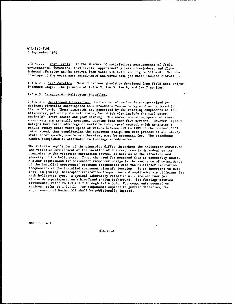
M1L-STD-810E ] September 1993
1-3.4.2.2 Test levels. In the absence of satisfactory measurements of field environments, functional test levels approximating jet-noise-induced and flow- induced vibration nay be derived from table 514.4-111 and figure 514.4-8. Use the envelope of the worst case aerodynamic and worst case Jet noise induced vibrations.
1-3.4.2.3 Test duration. Test durations should be developed fro» field data and/or intended usage. The guidance of 1-3.4.9. 1-4.3, 1-4.6, and 1-4.7 applies.
1-3.4.3 Category 6 - Helicopter installed.
1-3.4.3.1 Background information. Helicopter vibration is characterized by dominant sinusoids superimposed on a broadband random background as depicted Jn figure 514.4-9. These sinusoids are generated by the rotating components of the helicopter, primarily the main rotor, but which also include the tail rotor, engine(s), drive shafts and gear meshing. The normal operating speeds of these components are generally constant, varying less than five percent. However, recent designs have taken advantage of variable rotor speed control which generates a' pseudo steady state rotor speed at values between 951 to 110X of the nominal 1001 rotor speed, thus complicating the component design and test process as all steady state rotor speeds, pseudo or otherwise, must be accounted for. The broadband random background is attributed to fuselage aerodynamics.
The relative amplitudes of the sinusoids differ throughout the helicopter structure. The vibration environment at the location of the test Item is dependent on its proximity to the vibration excitation source, as well as on the structure and geometry of the helicopter. Thus, the need for measured data is especially acute. A clear requirement for helicopter component design is the avoidance of coincidence of the installed components" resonant frequencies with the helicopter excitation frequencies at the installed component aircraft location. It is Important to note that, in genera.l, helicopter excitation frequencies and amplitudes are different for each helicopter type. A typical laboratory vibration will include four (4) sinusoids superimposed on a broadband random background. For fuselage-mounted components, refer to 1-3.4.3.2 through 1-3.4.3.4. For components mounted on engines, refer to 1-3.4.1. For components exposed to gunfire vibration, the requirements of Method 519 shall be additionally imposed.
HETJIOD 514.4
514.4-18

MIL-STD-810E 1 September 1901
TABLE 514.A-III. Broadband Vibration test values for let aircraft emilprcept.
Criteria
Aerodynaalcally Induced vibration (figure 514.4-8) 1/
Functional test level 2J
W0 - K(q)1
Jet engine noise Induced vibration (figure 514.4-8) \J
Functional test level U. ±/. UJ, £. 6/
U„ - (0.48 (cos*6)/10[Dc (Ve/A)3-t-Df(Vf/A)
>]
K - 1.18 x 10"u for cockpit panel equipment and equipment attached to structure In compartments adjacent to external surfaces that are _ smooth, free fron discontinuities. (K - 2.7 x 10'* If q is in lb/ft»)
K - 6.11 x 10"n for equipment attached to structure in compartments ad- jacent to or immediately aft of external surfaces having discontin- uities (cavities, chines, blade antennas, speed brakes, etc.) and equipment in wings, pylons, stabilizers, and fuselage aft of trail- ing edge vlng root. (K - 14 x 10"* if q is in lb/fts)
q - 57.46 VS/a2 (1200 lb/ft*) or maximum aircraft q, whichever is less.
De - engine core exhaust diameter, meters (feet). (For engines without fans, use maximum exhaust diancter).
Df - engine fan exhaust diameter, oeters (feet).
R - minimum distance between center of engine aft exhaust plane and the center of gravity of installed equipment, meters (feet).
V. - engine core exhaust velocity, meters per sec (feet per sec). (For engines without fans, use maximum exhaust velocity without after- burner) .
V, - engine fan exhaust velocity, meters per second (feet per sec).
0 - angle between R line and engine exhaust axis, aft-vectored, degrees.
A - 1850 If engine exhaust velocities are in feet/sec.
A - 564 if engine velocities are in meters/sec.
HF.THOD 514.4 514.4-19
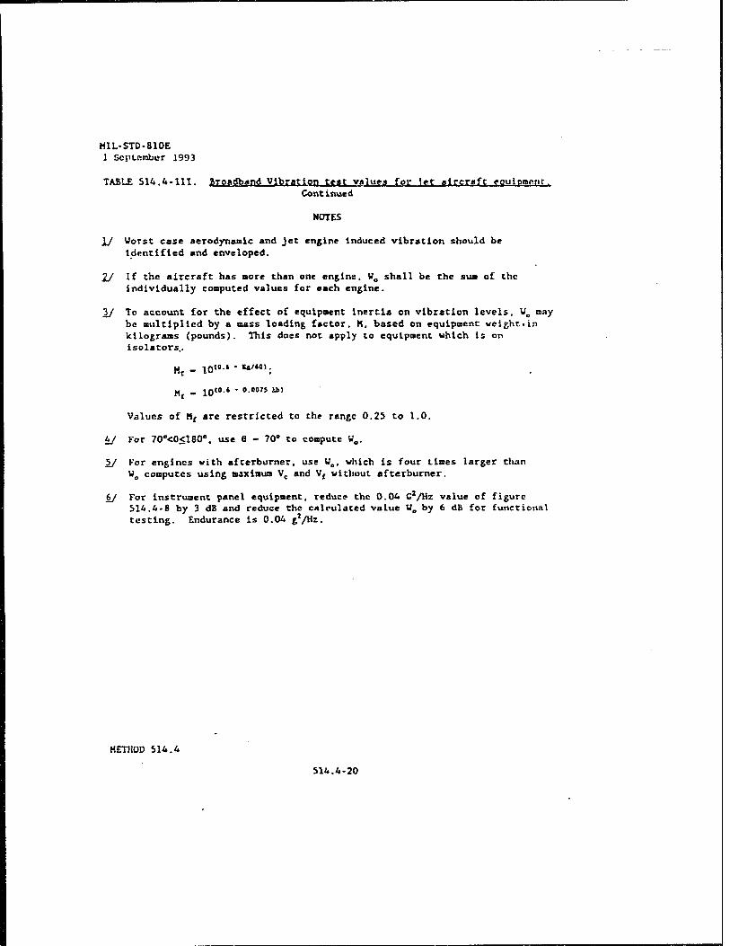
HIL-STD-810E 1 September 1993
TABLE 514.4-111. Broadband Vibration teat values for Jet aircraft equipment. Continued
NOTES
\J Worst case aerodynamic and jet engine Induced vibration should be Identified and enveloped.
2/ If the aircraft has »ore than one engine, V„ shall be the sua of the individually computed values for each engine.
3/ To account for the effect of equipment inertia on vibration levels. VB may be multiplied by a mass loading factor, K, based on equipment weight■in kilograms (pounds). This does not apply to equipment which is on isolators,.
Ht - 10"-» -**/«<».
Values of Mf are restricted to the range 0.25 to 1.0.
4/ Kor 70"<0<180°. use 8 - 70° to compute U0.
£/ Kor engines with afterburner, use Wot which is four tines larger than W0 computes using maximum Vc and V( without afterburner.
6/ For instrument panel equipment, reduce the 0.04 C*/Hz value of figure 514.4-8 by 3 dB and reduce Che calculated value W0 by 6 dB for functional testing. Endurance is 0.04 g*/Hz.
METHOD 514.4
514.4-20

M11.-STD-810K
1 Sii')>ii>mlx»r 1 •)■).»
I CO»
1000 MOO
Figure; bl6.A-B. Vibration t?st spectrum for jfft cirrrnft.
MKTI10D !>V. .4 SWi.4-71

M1L-STD-810E ] September 1993
EQUIPMENT LOCATION w. w> Ft
General .001 .01 500
Instrument Panel .001 .01 500
External Stores .002 .02 SOO
0 On/Near Drive 1 Train Elements .002 .02 2000
Hz
wi
wo
Ä1
A2
A3
"A4
Figure 514.4-9. Vibration spectrum for equipment mounted on helicopters.
METHOD 514.A
514.4-22

MIL-STD-810E
1 September 1993
1-3,A-3-2 left frequencies.. For laboratory teat purposes, the aircraft can be divided into thrae zones as depicted in Figure 514.4-10. For components located in the vertical projection of the sain rotor, the laboratory test frequencies are the fundamental rotational frequency of the main rotor (IP) and the harmonics of IP multiplied by the number of blades in the main rotor system (n). For components located in the horizontal projection of the call rotor, the laboratory test frequencies are the fundamental rotational frequency of the tail rotor (IT), and the harmonics of IT multiplied by the number of blades in the tail rotor system (o). Thus, laboratory test frequencies (labeled F,, F2, F, and Ft) for a component located In the vertical projection of the main rotor are determined as:
Fj - IP Fj - nP F, - 2nP F, - 3nP
A similar calculation is made for components located in the horizontal projection of the tall rotor. The fundamental main and tail rotor frequencies and the number of rotor blades are defined for various helicopter types in Table 514.4-V. All equipment located on or in close proximity to the drive train such as gear boxes and drive shafts should use the source frequencies of that drive train component (i.e., gear mosh frequencies, shaft rotational speeds, etc.). These drive train source frequencies are also aircraft- specific.
I-3-4.3.3 T.Mt »ffpUttiJes. The tost amplitudes are labeled Alt Aj. A, and A* and arc associated with excitation frequencies F,, F2, Fj and F4. Whenever possible, the test amplitudes for equipment installed on helicopters should be derived from aircraft measured values at the component installation location. These measured amplitudes are then amplified to derive a component test duration equivalent to the life of the component. The time-scaling is delineated in 1-3.4.3.4. However, when measured data are not available, the frequency-dependent amplitudes can be determined from Figures 514.4-9 «rid 514.4-10, and from Tables 514.4-IV and 514.4-V. These default amplitudes are an attempt at envoloping potential worst-cass environments; they do not rcpresont environment* under which vibration sensitive equipment should be expected to perform. However, the components are expected to survive and function to specification at the completion of the tost. Consequently, performance vibration amplitudes should be tailored to particular applications.
1-3-4.3.4 IPfft dyrflUon. Utilizing the default test amplitudes delineated in 1-3.4.3.3, the test duration shall be four (4) hours of excitation for each of three (3) mutually perpendicular axes for a total test time of twelvs (12) hours per component. If A teat amplitude other than the default amplitude is used, the test
METHOD 514.4 514.4-23

M1L-F7D-810E u J::.Y iysy
hCTHOD 514.4
!_
C
> I.
o L
u
•3 C c c IS
to It e> (3

MIL-STD-810E 1 September 1993
duration shall be scaled as follows:
where
t, =4.0
\f = actual test time pa axis AD = default test amplitude Ar ■ actual test amplitude
(■£■)•
The longest resultant y determined from the various combinations of the frequency-depeodent Ay/AD ratios shall be utilized.
TABLE 514.4-1 V. Default test peak amplitudes for equipment on helicopters. >
Equipment Location Source FnaucniryfFi} Ranze (Hzl atMf'5)
General (1) 3-10 10-25 25-40 40-50 50-500
0.7/C10.7-FJ 0.1 • F,
15 6.5-0.1 *F„
U
Instrument Panel (1) 3-10 10-25 25-40 40-50 50-500
0.7/C10.7-F.) 0.07 * F,
1.75 4.55-0.07 • F,
1.05
External Stores (1) 3-10 10-25 25-40 40-50 50-500
0.7A10.7-F.) 0.15 *F,
3.75 9.75-0.15 »F,
2.25
On/Near Drive Systems' Elements (2)
5-50 5O-2000
0.1 * F, 5.0 + 0.01 »F»
NOTES: (1) FJC « Excitation frequency, x * 1.2,3 or 4
F| " Fundamental excitation frequency (Rotor rotational speed) F2 « nFj or mFj (Blade passage frequency) F3 s 2nFj or 2mFj (Blade passage frequency) F4 =* 3nF) or 3mFj (Blade passage frequency)
where n (or m) = number of main (or tail) rotor blades (Table 5H.4-V)
Upon determining values of F|, through F4 (Figure 514.4-9), select the appropriate excitation frequency range for each to determine the peak amplitudes.
(2) F1.F2.F3.F4 must be determined from drive train areas for the particular helicopter. NOTE(l)isthen applicable.
METHOD 514.4 514.4-25

M1L-STD-810E 1 September 1993
10-<*-A Category 7A - Assembled extern»! stores, ^c aircraft. Assembled jet aircraft scores will encounter three distinct vibration envlronaents: captive flight, buffet maneuver, and free flight.
1-3.4.4.1 Captive, flight, Extensive measurement programs have shown that the vibration experienced by an externally carried store on a Jet aircraft-arises from three distinct sources:
a. Aerodynaaic boundary layer turbulence.
b. Buffet maneuvers.
c. Aircraft-induced vibration.
In general, store vibration is primarily caused by broadband aerodynaaic boundary layer turbulence and is relatively independent of Che carrying aircraft and mounting location on the aircraft. Instead, vibratory excitation is mostly influenced by store shape, mounting configuration and dynamic pressure. This source of vibration is distributed along the entire surface of the store and is difficult to simulate by point input of vibration, such *s from a vibration shaker, unless the store is relatively-stiff. Therefore, an acoustic test (Method 515) is recommended for this environment.
' " •., TABLE 514.4-V. Fundamental source freouencies fF,).
HELICOPTER MAIN ROTOR IP (Hz) TAIL ROTOR IT (Hz) n (Blades) m (Blades) (
AH-1 5.4 27.7 2 2 |
AH-6J 7.8 47.5 5 2 I
AH-64
CH-47D
4.8 23.4 4 4 I
3.75 1/ 3
MH-6H 7.8 47.5 5 2
0H-6A 8.1 51.8 4
; OH-58A/C 5.9 43.8 2
OH-58D 6.6 39.7 4 2
1 UH*1 5.4 27.7 2 2
| UH-60 4.3 19.8 4 4
1/ The CH-47D has two (2) main Totors and no tall rotor.
METHOD 514.4
514.4-26

MIL-STD-810E 1 September 1993
1?;1-2;^2 Category h - properer A<Kr«fr The test item shall be installed In a vibration fixture which simulates the actual application configuration. To the extent practical, the vibration test setup should incorporate actual mounting and installation provisions fro» the carrying aircraft. Fixture designs wMch «iUze
the n.axin.u» amount of platform structure possible will allow the best lt.. to respond
«cuS fieire^r^en"1011 '" * -""" ^ ^^ ^"^ "' response in'the
I1.-1.2.1.3 Category 5 • Jet airrmff (See II-1.2.1.2 >
":1-2;1'* Cat°K°rV 6 - Heljrnprrr, The test item «h*ll be attached to the vibration exciter by means of a fixture capable of transmitting the vibration conditions specified. The fixture shall be designed by utilizing actual racks. panels or platform structures of the helicopter to minimi« the introduction of unrepresentative response within the test item.
11-1.2.1.5 Category 7A ■ Assembled external «fores, ier a<rcrj.fr
1I-1.2.1.S.1 Fixtures, Suspend the store from a structural support by means of its normal mounting lugs hooks and sway braces simulating the operational mounting configuration. Include launcher or mounting rails where applicable. Rieid body store suspension modes shall be between 5 and 20 Hz except that the highest rigid body mode shall be no higher than one half the lowest test frequency. In some instances in the past stores have been hard mounted to large shakers. This has proven to be inadequate and should not be attempted.
Vibration shall be transmitted to the store by means of a rod or other suitable mounting devices running from vibration shakers to the surface of the store The tie points on the store surface shall be relatively hard and structurally supported by the store internal structure or supported by an external fixture (usually a rin* around the local store diameter) attached to the store. Separate driving points will
^n/?qU i C0{drWe thc verical and late«l ««• Separate driving points at each
end in each axis are also recommended although aligning a single driving point in each axis with the store aerodynamic center has also been successful.
llll'2'l'5il Acceler°Tt<T?, Accelerometera to monitor the vibratory response of the store should be mounted on two relatively hard points or rings within the store, one in the nose section and one in the aft section. For stores such as bombs with nonintegral tail cones, the aft-section mounting point should be in the aftmost section of the main body of the store. At each mounting point or ring two accelorometers should be mounted--one in the vertical and one in the lateral plan (Longitudinal direction is along the axis of the store; the vertical direction is' defined as perpendicular to the longitudinal axis and contained in a plane passine through the mounting lugs). v passing
METHOD 514.4
516.4-56

MIL-STD-810E 1 September 1993
vSbr.Uo^^rl^rJ ' CrmH T*"'' ^ "" lteB >h-n b' "tached co the vibration generator directly or with a fixture, and securely held by Its normal ! T at"^"e- *»» "«ur. «hall incorporate actual Lrvlce «tructur™ L ex^Sure
POS: U t0 ■i?1'1" »*"-"•«« "*P»n«e character"«« during test Hke Ihall^ COM,eCti0n to che test i««. ««A «5 cable«, pipes, vlref an5 the ««.«? i1 *rranfed " that it i»P0«S restraints and «Lass stall.r to those K^tion'shall f"uiP»ff H
is ^-tailed m the operational configuration Excitation shall be applied through the three orthogonal axes of the test ice».
11-1.2.1.9 C«c*R9ry 9 . ghjphoarrt, Equipment should be aounted in Its normal configuration with nor»al «hock/vibration isolator aounts Zlthroughout tT
tcst^Phase^shanT^ ^ \VVT 'T™^ ^ SeCUred c"«° transportation test Phase shall be accomplished as indicated in 1-3.3.1. The additional
f xtüre%x:it«ureT:h"ui: roaplished vith the tesc ^ «•«««*irs. wÄ?i!; * lCh *" B0UnCed on vib«tion isolators should be tested -ctgona!Sa°i"!°n "^^ ^ £t~ ShaU *' ""ed in "<h •' three
«seilte aclua!dtrlnl7 'r^tlV ? ' ^f.e »sseably transport The test setup Secure thttT.l "ansP°rt v^icle and test track to siaulate service conditions. Secure the test ite» on the transport vehicle for noraal transportation.
"-1-2-3 Procedure TTI - Cut»fnry 3 -Loos» ,-»rPO t»ncrrr
"igure'sil /»^Thr«'.- ^ te" ?etUP MeS * PaCka«e Ce«"r ** dePi«ed i" to thl II A? J; fi»uring required is as shown and will not secure the itea iLtl 5 ? I, Pc^ge teSter- A vertical iapact vail and sideboards as
«..,!:.:" Package tester The fence opposite the vertical iapace wall is not
the tester* •ÜTELü^T^ ** "T* " "St"ln *» C"C lteB «« Wi"S nrLÜr distance to this restraining fence should be sufficient to prevent constant iapact. but still prevent one or «ore of aulclple test items LtdeWriXnS aW"y "?? "" 0th"S- "» hei8ht •' the te« enc osure ihan t£ KS; iT raU "nd "st"lni"6 force) should be at least 5 ca higher
s= 2rrsj :i £ i^ur:.'0 prevent unreaii"ic'—«-•< - -"
METHOD 514.4 514.4-57

M1L-570-810E I- MY 1909
a >
kETHOD 514.4
»» 3 O w O «J
-« 3 Ik K
»4
e o — e e &.><?■
* M : ~* eJ
i» a» ■ S •«. C • «■* — < I-
514.4-5B

MIL-STD-fllOE 1 September 199 3
II -1.2.3.2 Test bed. Foe tasting packaged iteos, the tact bed of the package tester shall be covered with a panel of 1/2-inch plywood, with the finished side up and the grain parallel to the drive chain. (Marine plywood Is recoaaended because it is generally aore durable.) The plywood shall be secured with bolts or six penny nails, with tops of heads slightly below the surface. The bolts or nails shall be spaced at sufficient Intervals around all four edges and through the center area to prevent "oilcanning* of the plywood.
For testing of unpackaged Itens, the test bed of the package tester shall be covered with a steel plate, 5 to lOma thick. The plat« shall be secured Co the bed of the package tester with bolts having the heads slightly below the surface. The bolts shall be spaced at sufficient Intervals around all four edges and through the center area to prevent 'oil canning' of the plate.
1I-2 rRWrVRATlW FW TEST
11-2.1 Central preparation
Step 1. Ferforn life cycle analysis described in section U of this standard
Step 2. Identify test categories which are applicable and pertinent from the life cycle analysis.
Step 3. Deteraine test conditions for each applicable and pertinent category.
Step 4. Select appropriate test apparatus, data collection and analysis equipment.
Step 5. Prepare the test itea in accordance with Ceneral Requireaents, paragraph (\ and as specified for the test category.
Step 6. Examine the test itea for physical defects, and docuaent the results.
Step 7. Conduct an operational check and docuaent the results.
Step 8. Proceed to the required test procedure if no probi ens arc found; otherwise, correct the problem» and restart with step 6 above.
11-2.2 fj,gc£durc III, -.Loose cargo .trftqgPg.JX.,
a. Packaged (teas. Using suitable wooden sideboards, the tent ltea shall be constrained to a horirontal notion of Sea (free space) in a direction parallel to the axes of the shafts • a distance aore than sufficient to ensure the test itea(s) will not rebound froa sideboard to sideboard (i.e., the distance between sideboards shall be equal to the width of the test ltea plus 5c«). Initial positioning of the test itea will be such that there are 2.Sea of space on either side. If aore than one similar ltea is tested simultaneously, 2.Sea of additional free space per additional ltea should be used between sideboards; the initial spacing should have 7.Sen between test items and 2.Sea to each sideboard. The total free space should not exceed the length of the longest horizontal axis of the teat ltea (to prevent test ltea rotation). Multiple similar test iteras shall not be separated by sideboards unless specified in the requireaents docuaents.
HKTllOD bWi.'i 514.A-59

Hlt.-STD-RIOE ) Kept froher 199i
b. Circular cross-section Itea*. The test «Tea on the package tester (see Figure SW».4-19) shall be square In shape. The following formula shall be used to determine the test area dimensions:
x - 0.767 * L « <N)* where:
x - length of each side of the test area L - length of Cho teat ltea N - number of test itras If H>3 For values of N <3, xjl.b L
c. Other unpackaged test lteas. If the packaged ltea Is square or rectangular In shape, use the fencing arrangement for packaged lteas as detailed above.
11-3 PBOCEfiMLES
11-3.1 Procedure }
11-3.1.1 General procedure
Step 1. Complete steps 1 through 8, paragraph 11-2.1.
Step 2. Inspect the test ltea to establish pretest criteria and physical condition.
Step 3. Verify the test ltea's functionality,
Step 4. Mount the test ltea on the vibration equipment as required by the applicable paragraph of 11-1.2.1.
Step S. Expose the test ltea to the test level and duration as deterained from 1-3.3 or 1-3.6 and 11-3.1.2. The test ltea shall be operated as If It were in operational usage. (See 1-6.10. 1-4.11 and 1-4.12.)
Step 6. Inspect the test ltoa and compare It to pre-test data and physical condition. Verify the tust itea functionality and record the results. (See 1-6.11)
Step 7. Repeat steps 2 through 6 (see 1*6.6) for each axis (sec 1-6.2.5) and each tost.
Step 8. Document the test results in accordance with 11-6.
11-3.1.2 Special cop»l.dora_tJL©rj£
II-1.1.2.1 Caterorv 7A Assembled external store», jet aircraft
Step 1. Apply broadband vibration to the store using an input, sped run shape of the Kture.-mounted forward nccclcronetcr response spectrum from 1-3.6.6. The input level should be 6 dB down froa the calculated response level of the forward accelcromctcr.
.Step 2. Identify those frequencies at which the store-aountcd acceleroaetrrs, in the direction of applied vibration, exceed the applied Input vibration by 6 dB or greaLer. There may be different frequencies for the forward and aft acccleroaeicrs.
MKTIIOI) 514.4 Ü6.4-60

40-FOOT DROP TEST
6-33

Per ARRADCOM Environmental Testing Criteria (Drawing No. 8837375), a 40-foot free
fall drop test was performed at ambient temperature in the following manner. With the use of
two slings, the MRC, in its wooden shipping box, was elevated to a height of 40 feet 0 inches by
a crane. With the aid of a helicopter quick-release mechanism, the MRC and shipping box was
allowed to free fall onto a hard unyielding concrete surface, contacting the bottom surface of the
shipping box. This orientation was selected due to the most likely orientation during slinging
operations. Prior to the release of the shipping container, both high-speed and standard video
tape cameras were started to record and document the drop test. Upon completion of the drop
test, standard 35mm photos were taken to document damage to the shipping box and MRC.
Prior to and upon completion of the test, helium-leak tests were conducted on the MRC to
determine if the container maintained the minimum leak integrity of 1 X 10" cc/he/sec/atm.
This engineering test was conducted to determine the survivability/leak integrity of the MRC
after the 40-foot drop test.
6-34

PART 7
TEST RESULTS
ROAD TRANSPORTABTI-TTY TESTS
Prior to initiating transportability tests, a helium-leak test was conducted on the SRCXX
S/N EE028TB which had a leak integrity better than 1X10 "6cc/he/sec/atm. Road
transportability tests were completed on 23 January 1997, with the SRCXX tested in its standard
shipping box. At the beginning of the test, the container was located over the rear axle of the
Commercial Utility Cargo Vehicle (CUCV) (this vehicle is similar to a standard pickup truck
that would be used at formerly used defense sites [FUDS]). Times recorded during the first two
passes over the road hazard course were 27 and 31 seconds, respectively. These times represent
approximately 5 mph, which is required for the test plan. Following the first two passes, the
shipping box moved forward and centered on the truck bed, with no damage sustained. After
completing the 30-mile road trip the shipping container still remained centered on the forward
section of the truck bed, again with no damage noted. Two additional passes were then
completed over the road hazard course at 31 and 32 seconds, respectively, with no damage
occurring to the SRCXX or its shipping box. Panic stops were conducted at 5, 10, and 15 mph
and 5 mph in reverse, with no damage occurring. This test was conducted IAW the test plan to
make sure that the SRCX would not be damaged during emergency stops. The washboard
course was the last test conducted, and introduced severe shock into the SRCXX and shipping
box to ensure no damage was sustained to the SRCXX or shipping box during severe transport.
Upon completion of all transportability tests, the shipping box had sustained no damage, with the
SRCXX still maintaining a leak integrity of better than 1X10" cc/he/sec/atm. The above tests
met the requirements for ASTM-E499-73, Method B, and DAC TP-94-1.
7-1 ■

ÜSSF
HIGH- AND LOW-FREQUENCY VIBRATION TESTS
High-frequency vibration tests were conducted by Datasyst in Delafield, WI on the SRCXX
S/N EE0028TB. Prior to high-frequency vibration testing, helium-leak testing was conducted on
29 January 1997 with the container having a leak integrity of better than 1X10" cc/he/sec/atm.
The high-frequency test sequence was completed in the following manner: the container was
preconditioned to -35 degrees Fahrenheit with 4 hours of helicopter and 1 hour of aircraft
vibration completed in the longitudinal direction. The vibration spectrums for these tests were to
500 Hz for helicopter and to 2,000 Hz for aircraft. The container was then preconditioned to
165 degrees Fahrenheit with the longitudinal testing again repeated for 5 hours. After
completing longitudinal testing the environmental chamber was removed with the container
rotated 90 degrees for hot and cold lateral testing. The environmental chamber was reinstalled
with the container again preconditioned to -35 degrees Fahrenheit followed by 5 hours of
vibration testing. After completing this cycle, the test sample was preconditioned to 165 degrees
for the final 5 hours of testing. Total time for high-frequency vibration testing was 20 hours.
Upon test completion, the container was inspected for damage and helium-leak tested. The
general condition of the container was still good with it maintaining a leak integrity of at least
10" cc/he/sec/atm. See part 8 for graphs depicting the high-frequency vibration testing. On
6 March 1997, the SRCXX S/N EE028TB was again preconditioned to -35 degrees Fahrenheit
for the low-frequency vibration test. This test was conducted at 5 hz for a period of 20 minutes
during which time severe shock was introduced into the container body. Following this test the
container was helium-leak tested with it still maintaining its leak integrity of at least
10" cc/he/sec/atm. The container was then preconditioned to 165 degrees Fahrenheit followed
by another 5 hz 20 minute low-frequency vibration test. After all vibration tests were completed,
the container still maintained a leak integrity of better than 1X10" cc/he/sec/atm. The above
tests met the requirements for ASTM-E499-73, Method B, and MIL-STD 810E, Method 514.4.
7-2

UNITED NATIONS fl Ml PERFORMANCE ORTENTED PACKAGING (POP) TESTS.
UN POP tests were conducted on the SRCXX S/N EE0028TB. Prior to and immediately
following each test, the container was helium-leak tested to ensure leak integrity. The
compression test was conducted 3 March 1997 at 2,000 pounds for a period of 24 hours. End of
test inspection indicated no damage, with the container still maintaining its leak integrity.
Vibration tests were conducted on 25 February 1997 in the following orientations: parallel,
lateral, and vertical directions to the container body. Each test lasted 1 hour per orientation.
After completing all tests, the container had no damage to the container body, and still
maintained its leak integrity. Hydrostatic tests were conducted on 3 March 1997 on
S/N EE0028TB at a pressure of 60 psi for 3 minutes, no leaks occurred. The pressure was
increased to 200 psi for an additional 3 minutes with the container not leaking. Drop tests were
conducted on S/N EE0028TB on 25 February 1997 from 5.9 feet. Following each drop, helium-
leak testing was performed. The first three drops were longitudinal to the container body,
impacting on the seam weld. After each drop, helium-leak tests were conducted with the
container maintaining a leak integrity of better than 1X10" cc/he/sec/atm. The next three drops
were 45 degrees to the container flange/lid directly in line with a bolt. After each drop the
container was rotated approximately 45 degrees to avoid impacting the same area on the
container lid. On the first drop at 45 degrees no leaks were detected; however, after the second
drop a slight leak in the 10" cc/he/sec/atm range was detected. The container flange was
cleaned, a new gasket installed and the bolts were tightened and the leak disappeared. To
complete the required six drops with no leaks, this container was dropped a sixth and seventh
time with no leaks detected. Hot and cold drop tests were also completed 7 March 1997 on
S/N EE0028TB, with no leaks detected at 165 degrees Fahrenheit or -35 degrees Fahrenheit after
testing. The above tests met the requirements for ASTM-E499-73, Method B, and UN POP Title
49CFR, Section 178.6.
7-3

40-FOOT DROP TEST
This engineering test was conducted 22 April 1997 on SRCXX S/N EE0028TB. Prior to
the drop test, helium-leak tests were performed, with this container having a leak integrity of at
least 1X10" cc/he/sec/atm. Total drop weight during this test was 400 pounds which included
the SRCXX (135 pounds) plus wooden shipping container (70 pounds) manufactured by
Teledyne Brown Engineering. After free falling from 40 feet and impacting a concrete surface,
extensive damage was sustained to the container sidewall at points of contact with the 2- by 4-
inch wooden cradles (see photos in Part 10). Although damage was noted to the container
sidewalls it still maintained a leak integrity of at least 1X10" cc/he/sec/atm. To avoid damage
in the future, new production should include a redesigned cradling system.
7-4

PART 8
UN POP TESTS (STANDARD FORM^
SRCXX United Nations (UN) Performance Oriented Packaging (POP) Tests
U.S. Army Defense Ammunition Center
SIOAC-DEV, 3700 Army Depot Road, Savanna, IL 61074-9639
815-273-8908
Jerome H. Krohn
Test Report Number: 97-03
Product NSN: N/A
Shipping Name: *
Hazard Class: Poison 2.3, 6.1 and/or
Explosive 1.2K
Physical State: *
CAA Number: *
CFR 49 Packaging Method: E-102
Net Explosive Weight: *
Service Code: DEV
Nomenclature: SRCXX
UN ID Number: *
Packing Group: I
NALC/DODAC: *
EX Number: *
DESCRIPTION OF PACKAGTNGS TO BE TESTED
EXTERIOR CONTAINER
Exterior Container: Drum (Removal Head)
CFR 49 Reference Number: 173.7A
UN Code: 1A2
* See Interim Hazardous Classification for following items.
NSN Exterior Container:
8-1

Specifications: 1A2 Drawing Number: 15-12-422,15-12-443, 15-12-444, 15-12-445, 15-12-446, 15-12-447, 15-12-448,15-12-511
Net Quantity Weight: 205 lbs (93 kg)
Tested Gross Weight: 340 lbs (155 kg)
Dimensions Interior: L-51-1/4" X D-l 1-3/4"
Manufacturer: Teledyne Brown Engineering
Year Container Manufactured: 1996
Drawing Number(s): 15-12-442
Cushioning: Vermiculite
Closure: 10 Bolts
INTERMEDIATE CONTAINER
Intermediate Container Description: None
Specification Number: N/A
Container NSN: N/A
Intermediate Container Cushioning: N/A
Intermediate Container Closure Method: N/A
Intermediate Container Dimensions: N/A
Number Of Intermediate Containers: N/A
UNIT CONTAINER
Unit Container Description: None
Unit Container Specification: N/A
Unit Container NSN: N/A
Unit Container Cushioning: None
Unit Container Closure Method: N/A
8-2

Unit Container Dimensions: N/A
Number of Unit Containers: N/A
SPECIAL NOTES
All exterior, intermediate, and unit containers must be inspected prior to use. Inspect for physical damage,structural integrity and leak proofness of the containers.
SUPPLEMENTAL INFORMATION
Permitted Transportation Modes: Military or DOD licensed truck, Military or DOD licensed aircraft.
Specific Gravity: N/A
Hydrostatic Test Pressure Applied: 60 PSI
Leakproofness Test Applied: Helium Leak Test at 1 X 10 " cc/he/sec/atm
TEST PROCEDURES
Tests Conducted
(1) Pre-Conditioning (fiberboard)
(2) Drop Test
(3) Leakproofness Test (1 X 10 "6cc/he/sec/atm) Part 178.604
(4) Hydrostatic Pressure Test (60 PSI)
(5) Stacking Test (2,000 lbs)
(6) Vibration Test
Test Method Test Results
Part 178.602 N/A
Part 178.603(e)(l)(ii) Pass
Part 178.604 Pass
Part 178.605 Pass
Part 178.606(c)(1) Pass
Part 178.608(b)(3) Pass
8-3

UN POP Marking
u 1A2/X155/S/96
nUSA/DOD/DEV
CERTIFICATION
Unless expressly stated to the contrary, we certify that all of the above applicable tests have been
performed in strict conformance to CFR 49, Subpart M, Parts 178.600 -178.608. Based on the
successful test results shown above, this container is deemed suitable for transport of the hazardous material described herein, provided that maximum tested weights and quantities are
not exceeded and the packaging is assembled as tested. The use of other packaging methods or
components may make this test invalid.
PREPARED BY -Uli DATE: L "Z^/^?p
PREPARED BY:
WILLIAM R. MEYER
Test Engineer
■ mK Q. to BRADLEY7 J.|IAAS
DATE: (r~ M -°l 7
Test Engineer
SUBMITTED BY: \]/44*h*lS^
/JEROME H.KROHN
Chief, Validation Engineering Division
DATE
APPROVED BY: WILLIAM F. E&NST Chief, Logistics Engineering Office
DATE : t/WA
8-4

PART 9
SPECTAL PACKAGING INSTRUCTIONS (SPI)
9-1

AUG-21-97 THU 8:55 P. 01
SPECIAL PACKAGING INSTRUCTIONS (AMCCOM Suppl 110 AR 700-T5)
2. SPI NO (AD)P1365ESK/MRC-2
S. PART OR DRAWING NO P/N VARIES W/CNTR. SEE CHART ON PAGE 2
8. QUPAJNIT OF ISSUE * /EA.
& ICQ 10. UNIT PACK WEIGHT (APPROXLB)
13. LEVEL A UNIT PACK REQUIREMENTS
1. NATIONAL STOCK NÜMBEh
N/A
3. REVISION
«. FSCM 59678
11. UNIT PACK CUBE (EXT) CAPPROXFT) ^
4. DATE 20AUGUESTI997
7. MIL-P-116 CLEANING/DRYING"
12. WUT PACK SEE {EXT) (APPRO* FD *
MIL-P-116 METHOD STEPS
BAG. TTTM PT.ASTTC CNTR TTNTFRfPT.ASTTQ riTSfflON fyFRMTPTTT TTP\ PAD rFTRFRPinAPn
T.FATVSF.AT
SRC/MRP rewTPPTwr; r\rn? rrnsTiRF, WDNBOxrovFRPAr^ CT.05TmF,
DRAWING OR SPECIFICATION
PPP-B-2fi PPP-B-7.fi MTT.-V-7lg7fi ASTM-T> 4777
SEE CHART PAGE? TOROTTKROTT«; SKF.rWARTPAr.F7
LATTiKMEE-TjaoSL 8794642
STYLE TYPE GRADE CLASS SIZE (INSIDE DIMENSIONS IN INCHES) AND REMARKS
SIZE TO FIT CNTR. USED 29.25"X9"DIA.(1EA.) AS REQD AS REQD. 1EA. NA 1EA. AS REQD. 1EA.
14a.
14b.
LEVELB: METHOD.
LEVEL C: METHOD 03 NOT APPLICABLE
fx| NOTAPPUCABLE G SEENÖTE.
Q SEE NOTE _
S^EC^EDMHEREciPACK*filNG AND PACKING 1"0U- BE IN ACCORDANCE WITH SPECIFICATION MIL-STO-2073-1 OR AS OTHERWISE
16. MARKING WILL BE IN ACCORDANCE WITH MIL-STD-129.
i!;.^fSFi^A.TiSN5, STANDARDS, AND DRAWINGS LISTED HEREON OF THE ISSUE IN EFFECTON DATE OF INVITATION FOB BID FORM A PART OF THIS DATA SHEET. THE APPLICABLE GENERAL AND REFERENCED REQUIREMENTS OF SPECIFICATION ML-STO-Sw-i FORM PART OF T^JI ZTJL SHEET UNLESS OTHERWISE SPECIFIED, MATERIALS WILL BE MINIMUM SIZE IAW MlL-STO-20%-1 1 FORM PART OF THIS DATA
^FolS^^^^ 19. NOTES/DRAWINGS* WUJL CHANGE WITH HEM PACKAGED ~~~
A. THIS SPECIAL PACKAGING INSTRUCTION (SPI) IS PREPARED FOR USE BY THE PROJECT MANAGER (PM) FOR NON-STOCKPILE CHEMICAL MUNITIONS IN THE REPACKAGING OF CHEMICAL, TOXIC AND/ORSOTUOHVE ^F^ F0R TRANSPORT BY THE U.S. EXPLOSIVE ORDNANCE DISPOSAL (ORD) OR ARMY TECHNICAL ESCORT r^n*2 ragproounusro DEFENSE (FUD) SITES TO AN APPROVED STORAGE AND DTOALFACSSY (ASDF) (FOLLOWING IDENTinCATION OF THE (ITEM) IN A PERFORMANCE ORIENTED PACKAGING fPOPl rtJN PACKING GROUP I) TESTED CONTAINERS OF VARIOUS SEES IN ACCORDANCE WITH (IAW) UN PACKING ^JRUCnON: PI-101, WHEN ACCOMPANIED WITH AN INTERIM HAZARD CLASSIFICATION (fflQ ORSATCES) S^1^ F0R UNKNOWN/UNIDENTIFIABLE (WORST CASE) ITEMS. SHIPPING PAPERS OF ALL TOXIC CHEMICAL SHIPMENTS HAVING A UN SERIAL/INDEX NUMBER OF UN 0020 MUST BE ACCOMPANIED WITH CEFJTFTCATION OF EQUTVELANCY (COE) CCN AY 96-4« FOR IN COUNTRY SHIPMENT OR BY OBTAMING A
S1HS^1SSCS^AGE^)(C^
)F0R^
ONUS(0RC0NUS) A^CHEDTOSHIPPINGPAPJERSOFEACH
B. PACKAGING: PLACE BAG LINER (STEP 1) INTO MRC (STEP 5) AND ADD ONE (1") INCH OF CUSHIONONG (STEP 3) ^^^^£D£Y 0NE (1) lTEM PROJECTILE, BOMB, ETC.) ADD VERMCULTTE CUSHIONING (STEP 3) INTO BAG LINER TO COVER rrEM(S) TO A DEPTH OF ONE INCH OF (STEP 3)
(SEE CHART ON PAGE 2 OF 2.) 20. ITEM IDENTIFICATIONS CODE(S) 21. ITEMSI2E
* 24. NOMENCLATURE
SRC/MRC (VARIOUS SIZES-ANY ITEM)
22. ITENWT *
25.
l'^^Z/^-A,^/ PAGE 1 OF PAGES

AUG-21-97 THU 8:56 P. 03
SPECIAL PACKAGING INSTRUCTION (Continued)
NATIONAL STOCK NUMBER
N/A SPi NUMBER (PN)
(AD)P1365ESK/MRC-2
B. (CONTINUED)
(IF MORE THAN ONE ITEM IS PACKED IN THE SAME MRC CONTAINER, INSERT A FIBERBOARD PAD (STEP 4) AND ADD ONE (1") INCH OF VERMICULITE CUSHIONING (STEP 3) BEFORE INSERTING THE SECOND ITEM. INSERT ITEM AND COVER ITEM WITH CUSHIONING (STEP 3) TO A DEPTH OF ONE (1") INCH OR MORE). ADD CUSHION AS REQUIRED TO FILL BAG AND CLOSE AND SEAL THE BAG LINER (STEP 4) BY REMOVIN EXCESS AIR AND FOLDING, TAPING OR HEAT SEALING BAG. ADD TOP PADS (STEP 4) AS REQUIRED TO FORM TIGHT
PACK AND CONTACTING THE CONTAINER LTD (STEP 5) AT CLOSURE. SEAL THE MRC IAW THE CBDC SOP (STEP 6) AND PLACE MRC (STEP 5) IN THE WOODEN OVER PACK CONTAINER (STEP 7). CLOSE OVERPACK LID AND LATCHESAND INSERT WIRE TWIST (STEP 8) AND PLACE A LEAD WIRE SEAL (STEP 9-OPTIONAL) IN THE RIGHT SIDE LATCH.
C. MARK IN ACCORDANCE WITH MIL-STD-129-N AND AND AS A MINIMUM:
MANAGEMENT CONTRO;L NUMBER (MCN) QTY/NOMTNCLArURE PACK GROSS WEIGHT DWG./SPI): "(AD) P1365 ESK/MRC-2" COE/CCN AY 97-49
THE PROPER SHIPPING NAME MAY CHANGE WITH EACH ITEM PACKED. THE EXPLOSrVE HAZARD LABLE IS 1.2K OR AS SHOWN IN THE INTERIM HAZARD CLASSrHCATION TO BE CARRIED WITH SHIPPING PAPERS OF EACH SHIPMENT.
D. THE PERFORMANCE ORIENTED PACKAGING (TEST) MARKINGS ARE AS FOLLOWS:
(D 1A2/X + /S/** USA/DODDEV
** = INSERT LAST TWO DIGITS OF YEAR PACKED + = SEE CHART ON PAGE 3
NOMENCLATURE SRC/MRC (VARIOUS SEES-ANY ITEM)
PAGE NUMBER 2
NUMBER OF PAQES 3

AUG-21-97 THU 8=55 P. 02
SPECIAL PACKAGING INSTRUCTION (Continued)
NATIONAL STOCK NUMBER N/A
SPI NUMBER (PN)
(AD)F1365ESK/MRC-2
UDO SEE a. = CNTR b.=OVERPACK + POP TEST WEIGHTS
DESIGNED TO CONTAIN THE
FOLLOWING ITEMS CONTAINER DIA. LENGTH DWG. NO. EMPTY WT.
MRC (SMALL RRSTYFE)
7" 27.0" a. ACV-00500 b. ACV-O056O
55 lbs. 45 lbs
70.5 Kg 4.2 MORTAR 75 MMPR0J. 4.7MMPROI 2.63 ROCKET
155 MMPROJ
MRC (MEDIUM)
9" 41.0" a. ACV-00507 b. ACV-0074-6
100 lbs 75 lbs
141 Kg. LEVENS PROJ. 175 MMPROJ.
8" PROJ. 155 MMPROJ.
SRC X 11.75" 37.50" a. 15-12-442 b. ACV-577-79
120 lbs 70 lbs.
148 Kg. LEVENSPROJ 4.2" MORTAR 8" PROJ.
155 MMPROJ.
SRC XX 11.75" 51.25' a. 15-12-443 b. ACV-588-90
135 lbs. 60 lbs.
155 Kg. CAISPIGS M471bBOMB
175 MMPROJ. 8' PROJ.
MRC (SMALL BOMB)
12" 56.0" a. ACV-00566 b. ACV-00580-8;
150 lbs. 110 lbs.
164 CAISPIGS BOMB CHEM. 115/125 lb E46.E52, M70&M113
MRC (VXMINE)
16.50" 5.5" a. TBD b.
TBD TBD MINE AGENT M23 MINE CHEM (1 GAL)
+ = SEE CHART ABOVE FOR MRC CONTAINER, LOAD AND POP V HEIGHT INFORMATION
NOMENCLATURE SRC/MRC (VARIOUS SIZES-ANY ITEM)
PAGE NUMBER 3
NUMBER OF PACES 3
AMfWMU M>

PART 10
PHOTOGRAPHS
10-1

'-3?
» r
O) c 1_ 3
T3 X o Si
D) C Q_ Q. SZ CO co
_1 .ti „ c
< 7 X 7 X <r Ü > a: < CO CO CD . J
i sz X
in Zl ° o DC
H- ^ U) Z CD CD LU > ±3 O ^ <" Z CO c
o CD CO > 1=:
1- ° c5 z c: o
co x
s to o 5= -°
^ o c <r -£ ® co -a LU o o to ■« o z HI si * LL 111 Q T
his
mal
le
>- <o ^ T— . .
< O CD
^ o r^ Z
CO en
=> 21 w
Ü « CO 3 ri >.
A02
rt
ab
Ö g. Z «
C O fo 1- 4= O -o ^ 5 Q. 2
10-2

■■■■Hi W§fBm IsPJlllllplI |MP(MHIP WsmKnM ■IilllIlI»B
Jfi^ iiä^~.-:-
_l
< z z < > < C/) en
1 cz (Z "GO III (U H Z
-1—'
(1) 111 c£ o CO
z o O h- DC z (D z> <U ^ s H—
< o III <; U) <u z i> LLI CD li > HI o n c >-
CO GO
^ ^ Q: o <r XI
Ü)
c/) o -1—*
~) Ü x: Q. to .c h-
o CO o h- G)
Ü < Q
10-3

U.S. ARMY DEFENSE AMMUNITION CENTER SAVANNA, IL
PHOTO NO. DAC-97-03-02. This photo shows damage sustained to the SRCXX after the 40-foot drop test.
10-4

PART 11
GRAPHS
11-1

^ a: m
< z
o CO 1-
o
O u I CO I
CM
o CM
m
CO Q:
o X LÜ
ol
m
o o CM
O in
o o o 10
(d) 3dniVy3dlAI31

^ a: ! <
LU !
o to M z
Ü Q O
x 1 x 1 o rr I o CO 1
CO
CN
CO a: O X
LU
I-
o i
o CN
O CO
O o m
(d) 3dniVd3dlAI31

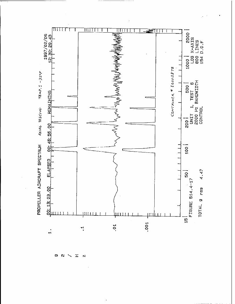
r- o T m •
r-- T T-i
T m B c
in 01
LÜ □: _J 3 < CD H M O
in
o o
O) CV1 X X N

o o in en
M (Si it X 111 < 21 n
i M X _l Q
CD O T O O in _J CO ■*H
o o cu
T UJ
Q M
o H 3= o UJ Q ■rt LU 7
V- <
■H N _j X u
H 0 h- o l-l 0 2 in -z. in O
=3 u
o CVI
in
m
CO CQ
OJ iH
OJ
T tn E
in 0)
ILI re _J n < CD H M O u. H
O o
•«rl O o o
o o o o
en ru \ x N

CVJ o in in •
r^. V ■ri
■«r 01 E
in Ol
IxJ tr _J Z) < CD h- M o
_ U- H in
o o
01 cu N

o o
o o o
o o o o
O (\l \ I N

9 t- O
:;/;.:^'.'iyi ;; ::::i'*;-:!: i-j:.';..:':! ■;■;:';■:: :^s:il;;;-:- -:i ■;■■ -: :
:;;h:i-' ■■!::::--!;: ::::::!v:-:':
:':fi;H:
:.!;:. ::..-.
-:i-5r
.:
:;;:::';:::: ;::;::;-:\
■F:
=1 ,: .,>
1 :: -'■';;
;'; ;i;j;:. ••:-::;.i-if:;-:'
r m :. /:; ■ ■:: ' iS}& /;; :i ■■:-;i
d "W';S:\:"-'.
::0 --.V» ■i "■'■: \-.-:.
■.X u * ■:.:.'~i<
•lihiMN; •■==#
0 ili -J
::::::!':J:' ...
\
T
- r
0 0
':: ::..cv. ::;:!:!;i:;ü:^
;;_:=;;
W[- 4 ///'■
'S- I^'lv;::!-'
;:;i;:;;;;:::;'r:;:::;
■J>
:!;:i:;:::!:r:!:::;i;:i;
■^:! ■•:-;:':^:
jj\:rf\-/, /T\ /
•■A:^ X/TY
§KH v v * v .
:i::;-::.: :l:-i:l :;:::^.:::: 1
,.:'
]S: ■:i- ::.-■': '-^ir^C^:!
HP ;:::;::.:i;..:
y-
• : '' ' :.'.\:'.'. .U%::\:- :::.::::'i:::.." ::i::;::::!:;-;:;i
i "(»II « :|!"?l R-V01» » /»mm q/H «11 GO WH S'SOVH

11
■ ■:■ ;':: \ -'■:
:!;•;-
i§|S;lJ\!liEB
•^:i:
:\mlM p!:;:!
:^:::- ::::::i::::!i-;:::!:::::::
\.,,M , . 1, llji:.-/
....,
■i'-äiii :'S^fiLyL .•nWRfflffnUiS
TTI ; !;..;:'.■!..:::;.:
!':.:.:* :
"^■***r." no
Z^;.
1 ;T!;
:;,;:;::;;;:
':;! . : !;-->;:::xr
■ :, :,-\::;'::
{■-;■-. V:::
<r < P s
1- i :;:-:"-
'.
1 ÜJ 1 i-^H:-1
-:::; Ji
d ' j J
0 U ::::::\3
1 r ::;:;;>* ;:!:;;$ 1-N? :iS:!i: f
:..■■!
■■'■■■ ■■
t ; T f !:.:r--: ■
V s) li ^■■Ti^ ... V
. \ : ::!:■"
m *
HiS :::>*• .:::::':':/. '.
~r-.i i::;::^:;:^
;.n-:
|||
■ ;V-':V::;rf:!
. ; :..: !::;:-;;X:i:i::i i-v;;::
::;;;::':j';'"-p;
;;: :;.:;i;;^i;; i:::\i:
/• 0 ire-
;!;:--b:-:; ;7-r-
:';-::: -W'M ;!;:::;;;
■VSHTWE I/™««! l):H-H IS •MW ■

1
4 »
C •r CD
£ 2 H <
J> 3T ? UJ
£ rr A
fc o o tr o
■^r «. T
a « ••H ro
V . * ~» o cr o i- u UJ Q. CO
Q UJ en
< tr
Q. < _J UJ
o cr H < o
o tr • UJ in _J TH
_i IK to Q. (\J O cr o D. o
o to m •
r^ V •rt ^r 01
■•rl E
in D)
UJ tr _I 3 < CD K- M O
_ u. H in
o o
O) CVJ N

tn M X <
I X
en u_ LU . 2 O Hi . -I Q
o o o in o -1 CD *-\ o
— ta o o in H cn
LLI
□ 3: □ < m
*■• N _i
M o 2 2 O O 3 CU O
cu o T in •
r^ V TH
T m E c
in O)
LU DC _J 3 < CD l- M o
m
o o
a w \ I N

o o
■ri O o o
o o o o
O) CVJ N

o o
o o o
o o o o
D) CU \ X N

:vli
c!
:::i3:-=::!fe <a 0 J
::ki.-|i
^= 1 o
*§ 0 .J
■—■': J Itf %: =3l=;-.^
U o a
J
■:■■■:}:.:
a C? T* ^ K : a •VT rf) :^ lÄ-; ':<-J:
!- :;!D h 1 :
;« ^ :...(.
:'£'.' ;$..
llÜr :ryi
l "1111 :i;|MI m'tllV-l •J/'O Tig: 1/X1I0I 7>:8I):SI tG 10 'W

3*
O, «• n«iiMI'«»|i I 1fe«ilMHlMCM#n
u/ I -1r'
p .::d'= i 0
* 3:* ;£
mnii>»iTi<.i<;-
-MITO 1/MW11 ;i:w=n tc'in'J »I/IOTOC q/«-mi ;i:g:;:i aim

PART 12
DRAWINGS
12-1

D T n M _ 1*
t to •3 *
E
T s 1-
X O
J. 5*
g z
$ f- z *
-1 a
" >- 9 i X o o a.
CD 3
B _J t> U> a %
hi s < tr in < m o 8 * L*. i-
- ? * N o s
(M "V J I
B
US m a E in
1 II
u o D «3 - O o - - a
if? si?
Us II »I
s»
<- u sir LÜÜJ 12 u5 — Z
■S 5! HS S5 si*
»8«
! E
? o i
as 3 1

t>
»* s« •i-i tin s|issisili= &' |:il:siis = | sk" ii * K -v «'»'S CC3U.
e et ! o D D D a ■ o .«
«
~ " K*i
Hi ?i| sis
E*S «*}
m UJ in in < LL)
CO
H
•«■ i
in
II li
ties;
o
i-i/xr
KL.UJ UJUJl «>ü:I-
<Z
OS. HS VIZ 3<
reij.oiijtö-iÄ
L.zoina.»uj< <<z<<™uia.
►-*■<£ .Km _Nfto3
>• . a — oic _j Oü-lu
?iiJja:<5iui-o
u. trz<ui <U.<<<0.<
z
cc
UJ z
o
cr > Ul
UJ
o Ul z
3 a 3 ►- (j z
1 _J \ < ■* UJ
U. 2 Z> 0. X o < J 2 UJ > L. UJ
J _i \ i
3 Z O
IP = X < L) uj a 5- <
5 s i 5 J g
UJ
1
rj


3E
-ES I E -
iß fii Hi
>- □ o CD
LU O 2 <
00 T f
55
« ;« ; .us-. I <1
Bit t H
s- *» - s2
£*§ «ISS»
£S I ■ 3 S £ e=«s ->^ "5
.gg.&iHfiär' "s t E( ! 11 ■ D ■ um j.
"751
s:

c_> JZ m
f\i
"O
m
-
ill •"5 •> t- a ; ^o
■ £5
S5'i
QJ m 3
. Bob
s füg
i 5
LD
B IS) 5 n
(M
<°!5 --JE
<}
m
Si B
==; s
si
3 ►< ii
ill e 3 I
111 H
a i2
53 ss\ t *■ K l-<
IE si D D D i
r\j
#" O
2 o D m in
6 r
in < D
t
o ^ CD

s:
JJt
if! ir
5 Es
»if! * w-
5s»
10
0. < u o en
■ hi il"s
B IB
<}

<\J
t>
m
•si-
in in UJ
^ £in o < orzo^ o
u2o> >- -J Q. <
< 111
<
SE
AL
DIV
IS
LUM
B
ON
. K
3 < tro^o
U. a: < • muj
in -j 0.OMJ UJ a.
a 75
00 in m o 2
in in
o o o in
Q. 0J
LdU en <o
o uu
_j
OQ: CEW 1-03 Z2 ^ OI3 * U2
— ^j — 0.
is 18 go „ S
*1 a • *- Sa P. -J
I i £ ss s £ P g a **» Q
[S 5 g as i 2
is* 2K>H Ss s
O O D D 0 I

3:
B
t
si« »6;
iff Sä«
<
o
s s Si
S£S3 3
9 to
Is! 5=i
sM 1
!J Is
I? **s
sie
?s>i = * ur tra:_i
„w * ? lOOOOh Ul.UIh
o a am ma <g «I 31

NUV-Ü4-9Ö HÖH 13:50 # . TBE MANUFACTURING ENG. m NO. 2057262926 P.03
■*
"T " " » i* -J
~1 '
3 xi 33.-h 3
+ ! i __ rv
•—••—■— —»— + -vcri
ÜOV

4 * VI1 l "
NüV-04-aß HÖH 13:50 m HRMFANURIK Effi. HftX NO. 2057262926 p m ^
SRC SHIPPING CONTAINERS
SIZE: -1 15 7/8" X IS 7/8* X40.0" INSIDE
-g 15 7/8" X 15 7/8" X 54.0" INSIDE
CONSTRUCTION:
INSIDE SKIN TO BE 1/4" PLYWOOD MIN
OUTSIDE FRAME TO BE STD1" X 2°
INSIDE SUPPORT TO BE STD 2* X 4"
FORK LIFT RAILS OUTSIDE TO BE STD 2» X 4'
ENDS TO BE 16.0" X16-0" NAILED OR STAPLED INTERNAL TO THE OUTSIDE SKIN
FORK LIFT RAILS TO BE 24.0 INCHES APART CSfTERED ON BOTH BOXES
TIE DOWN HOLES TO BE DRILLED THRU INSIDE SUPPORTS AND FORK LIFT RAILS

PART 13
APPENDTX
13-1

DETSI Project Number: U10-8762 February 1997
USADACS HAZARDOUS MATERIAL CONTAINER TESTING CHECKLIST
• Mark all PLOTS, PHOTOGRAPHS, and PAPERWORK with the number stamped Oh the flange of each container.
DONE (V)
NAME
I) Vibration Testing Horizontal (perpendicular to axis) A) Helicopter Spectrum
1) + 165[F Vibration Plot 2) +165 *F Temperature Plot 3) -35 [F Vibration Plot 4) -35 *F Temperature Plot 5} Test Set Up Photographs G) Video Segment
B) Aircraft Spectrum 1) + 165*F Vibration Plot 2) 4- 165 *F Temperature Plot 3) -35 [F Vibration Plot 4) -35 *F Temperature Plot 5) Test Set Up Photographs
II) Vibration Testing Horizontal Axially A) Helicopter Spectrum
1) + 165|F Vibration Plot 2) +165 *F Temperature Plot 3) -35 [F Vibration Plot 4) -35 *F Temperature Plot 5) Test Set Up Photographs 6) Video Segment
B) Aircraft Spectrum 1) +165*F Vibration Plot 2) +165 *F Temperature Plot 3) -35 [F Vibration Plot 4) -35 *F Temperature Plot 6) Test Set Up Photographs
III) Additional Requirements for the Final Report 1) A copy of the test specification 2) Löckhed Certification paperwork 3) Calibration Information and paperwork 4) Test Introduction 5) Test Procedure 6) T6St Conclusions 7) Photographs of the test set up 8) Equipment List
I) A)
1) S *t? 7K 2) i/ W -ns 3) is $i, TK 4) ^ 4d V^ 5) \S m TK 6)
B) 1) t/ 4? If 2) IS "7? 1K 3) i/ w TK 4) l^ #<< Vt- 5) s 3fn ^
ID M
.1) «/ 1? "7"* .2) V ft 7K 3) i/ ty -TK 4) v^
^ TK .5) i/ 2(h 77^ 6)
B)
1) \f Hi -7K. 2) \s~ & r/<- 3) \S & 77^ 4) is *(l TX 5) i/ %
III)
1»
-
2) 3) 4) 5) 6) 7) \A H* 77^ 8)
■

1/20/1996 15:27 ,'^J SURVtT SUMMA XT SHEET Page
SURVEY NO SURVEYOR
960680 MAZZOLA
SURVEYOR EVALUATOK
SUPPLIER : DATA SYSTEMS ENGINEERING t TEST ADDRESS : S. KTH.V. 33511 HVY 18 !DELAFIELD >: UI 53018
HONE : <*H) «HQ0V ONTACT : QUALITY." ~
CORP CODE t 960680 P CODE : D102201 t COUNT : 203017
A D A U S T C A D A U S 1 C P I P 1 P U E A P I P I P u r n P S P T E R R N P S P T E R R II R A R H N V H C R A R K N V H r. 0 P 0 U H D E 1 E 0 P 0 U H D F I [
V P V I E I Y H L V P V I E I Y N 1
E R E T L N A L E R E T L N A 1 D 0
V D H D G T
E E D
D 0 V
D H D G ]
F f
E C/A C/A D E C/A C/A 1) D D
QA SPECIFICATION TITLE
I8 HU-1-45208A INSPECTION SYSTEM REQHTS rxi i i i i i IK HIL-ST0-*5662 CALIBRATION SYSTEM REQMTS IXJ 1 1 i i i 04R NONDELIVERÄBLE SOFTUARE REQMTS 1 1 1 I i j*
L LMA SPECIAL PROCESSORS ONLY Ki i i i i i
l_._l_„l I I I
ill i i i
■JPPLIER HGHT
SURVEYOR
l.'AIUATOR

L OCKHEED MAß T/N
PROCESSOR: QUALITY CONTROL SYSTEM SURVEY RE PORT
STREET. S. U4TH W.33SH Kv/YlS
DATE OF SURVEY PERFORMED BY:
A. MAZ-Z.OLA DENS/EA
DIVISION:
AREA CODE:
CITY:
REQUESTED BY:
P-VfitnaL. KEY SUPPLIER PERSONNEL
PHONE NO: ■ <3fafl- 4O03 STATE:
DIVISION:
Derive. A.
NAME:
NAME: Ib/Mlb £. HotS(rt&,TOK> SF.
NAME lh5*AAte,<QKtM2&-
'NAME. /jiob^euj) LUo /S-OO^TZP/U
TOTAL NUMBER OF EMPLOYEES:
TITLE
SURVEY 110
ZIP CODE S3 0/6 XPRE;-AW/
RESUPV:
Qioe. F^esOe/JT /^cr l •(■.-/■'»'
TITLE
TiTL
TITLE
QUALITY CONTROL PERSONNEL: 2_
PRIMARY PRODUCT LINE: IJT,^ &P&A^#/V T", "T^//^ ^ JbTK YiLO&iX^T T^T/, \;
GOVERNMENT INSPECTION SERVICE/AGENCY: ^ I I RESIDENT I I ITIHER'Ti
QUALITY CONTROL SYSTEM REQUIREMENTS DOCUMENT SURVEYED TO: HiL-x- 4SZOSA M1L--STD-4S4>t=>Z A. COMMENTS:
SEE RECOMMENDATIONS ABOVE. APPROVED □ DISAPPROVED
SUPPLIER REPRESS (ACKNOWLEDGMENT OF DEBRIEFING)
ATlVE . DATE '
FORM: MMQ008
DATE/
LOCKHEED MARTIN EVALUATOR DATE

<
CO >.
CO
a
w UJ 1-
a K i
■4» \N
I O
O Z t- Ü UJ
o DC o_
V) ui u > DC UI CO i/)
^ 5
o
be UJ
CO
o
m 5
o CE CD z UJ
I 5 5
«I
o
z < o UJ GL CO
O
_l < DC UJ to
o z h- CC <
>• o Ü <
z o i- < IT m -i <
UI
Q 0* «- OS
5 £ ^9 ^ tx •^
a: >-
$
.0 n 5»
o 2« ex
UI a z
_J UJ Q O O Z 5
V»
>
3 O >-
0 0
•*> o IN
a
o
tr UJ cc
<
Z < 2
<*> 1 a i 5
>>•
< «0 o
O
3.
V
Ck
r- Z UJ 2 a. z> a UI
>-
UJ
*
«0 o to
ft.
10
o
o O
4
I S
|
0 n
o
•u u \u 0 u
8
V)
Ui
o
Ml J
e
N
o
1 3
rä O £ z
■•= h: ro £/) 2 111 a, K
±5 °S o CD a>? XI EC CO LU
(0 z J5 Ö
y> z to UJ JC H .2 W ■c > S Ü) to <
"O H m <
■o D
s • in — O) .=
■n ■" ^j
2 tu t/> 3 c a>
^ 2 3 cr
to ■- S a> c
o □. rä ra u tn -3
Si C o
Ü s o to £ Q.
to ■c o c
03 <0 o E o .y-m 2-t F o to 4- a> >
to S -a m
T3* to
« © c
«| to to CD
to 'S — n O O
7 .u 0) n P in a. to UI to TJ tl
P ifi > US § "5
DC UJ W
PAGE NO.

TEST EQUIPMENT CALIBRATION SYSTEM t Format Established with MIL-STD - 45662, 10 June 1980 ]
5.1 Calibration System Description
The following parametric transducer systems are provided with traceable reference standards for calibration.
O Acceleration Ö Temperature O Resistance O Voltage / Current O Pressure O Load O Displacement O Frequency
Reference and transfer standards are provided as follows:
H Reference (back to back) Accelerometer System O Portable Voltage & Frequency Signal Simulator O Portable Thermocouple Calibrator and Readout O Portable Digital Multimeter for Voltages (AC / DC),
Currents (AC / DC) and Resistance □ Transfer Standard Resistors Ö Dead Weight Pressure Tester Ö Micrometer Displacement Tester O Dead Weight / Force Load Provisions
The following external calibration services are utilized to provide traceability to in-house standards and calibration procedures -
O American Metrology ; Kenosha, Wl O West Caldwell Calibration Laboratories; West Caldwell, NJ Ö Precision Metrology; Milwaukee, Wl O Data Physics Corporation; San Jose, CA O Technimet Corporation; New Berlin, Wl O Accurate Gage, Inc.; West Allis, Wl
Also instrument manufactures are utilized to repair and recalibrate devices in specific situations as required.

5.2 Adequacy of Standards
The standards have sufficient resolution and accuracy to meet the provisions in specification requirements.
5.3 Environmental Controls
The measurement standards are stored and utilized in a suitable environment to maintain required accuracy. Measuring and test equipment are utilized within the limits of design criteria for each device.
5.4 Intervals of Calibration
The intervals of calibration are determined on the basis of the following:
O Noted stability of the device O After any repair or modification Ö Degree of usage O For particular close tolerance accuracy
requirements in critical projects.
Additional recall notifications are also provided by external calibration services for standards.
5.5 Calibration Procedures
Measurement standards are to be retained in the calibration standards office / laboratory, unless temporary usage at test site location is required or in transit to external calibration service facilities.
Measurement and test equipment systems shall have parametric effects established as required by usage along with basic single or dual point sensitivities for the individual devices or as system performance criteria.

5.5 Calibration Procedures (continued)
Manufacturers reference guides may be used where applicable.
Back to back comparisons are preferable where possible, and overall system performance and sensitivities established within the expectations of the static and dynamic requirements for the data acquisition.
5.6 Out of Tolerance Evaluations
If devices are found to have been used outside of design limits a calibration check is warranted with appropriate action taken to tag out of specification devices with recommendation for repair, recalibration or replacement.
The project expectation proposal shall be used as a basis to evaluate or correlate the measurement or data acquisition for reliability.
Critical testing may include before and after test calibration check on system performance to verify data accuracy.
Utilization of in-house forms is recommended for pre-test checks and documentation of actual testing measuring devices and calibration systems used in test programs.

SBPO2-AO15-0084
U.S. Army Small Burials Program
Weldment Inspection Report
For
Single Round Container
Serial Numbers: DD0010TB, DD0031TB, DD0049TB,
EE0001TB, EE0014TB, and EE0028TB
Contract DAAA09-95-D-0001
CDRLA015, Task 0002
Prepared For:
Department of the Army Project Manager for Non-Stockpile Chemical Materiel
Aberdeen Proving Ground, MD 21010-5401
October 8,1996
Prepared by:
U.S. Army Small Burials Program Teledyne Brown Engineering
HuntsviUe, AL 35807

SBP02-A015-0084 8 October 1996
Abstract
This Weldment Inspection Report documents the 100% X-Ray inspection of the seam welds for the following six (6) Single Round Containers (SRCs) being shipped to the U.S. Army Defense Ammunition Center and School for performance-oriented packaging testing. The welds were 100% X-Ray inspected as directed by Contract DAAA09-95-D-0001, Task Order 0002, paragraph 3.3.3. This report contains a copy of the SRC Shipment transmittal letter which includes verification that the X-Rays were accomplished per the task order, and copies of the X-Ray report for each of the six SRCs, as well as the results of welding inspections repeated on two of the six SRCs that were reworked following failure of the initial inspections. This report was prepared and is submitted in compliance with the referenced task order, paragraph 7.1, and Contract Data Requirements List (CDRL) Data Item A015.
Prepared By: Date: Approved By: Date:
'LloyclF! Silva Program Assurance Manager
Approved By: Date:
£~-<^ i oft fit W.A. Meyer, PE Director of Safety and Product Assurance
Approved By: Date:
'^Lj.^Uu^ MM &b0L„ st JL^jQöt 9c David R. Childers Manager, Task 0002
Approved By:
William A. Darme, PE Chief Engineer, Small Burials Program
Date: /o/yy>^
S/K Q^A^k^— Larry SyMaupin PrograiaManager, Small Burials Program
irraHWNE BROWN ENQNEERNQ CUMMINGS RESEARCH PARK 300 SPARKMAN DRIVE P.O. BOX 070007 HUNTSVILLE. AL 35807-7007
SBPO 96-244 (205) 726-1000 FAX (205) 726-1033
October 8,1996 VHS-0581-96
U.S. Army Defense Ammunition Center and School Mail Stop #25 ATTN: SIOAC-DEV/Mr. William Meyer Savanna, IL 61074-9639
Subject Contract DAAA09-95-D-0001/0002; Shipment of Single Round Containers
Dear Mr. Meyer:
Provided herewith are three (3) "X", and three (3) "XX" Single Round Containers (SRCs) which have been manufactured and initially tested by Teledyne Brown Engineering per the above contract, task order number 0002. These SRCs are being provided for performance oriented packaging testing as directed by Mod 1 to the aforementioned task order.
This is to further verify that the following six SRCs have successfully passed the tests indicated:
Serial Numbers: DD0010TB, DD0049TB, DD0031TB, EE0001TB, EE0014TB, and EE0028TB;
Leak Rate: Per section 3.3.1 of referenced task order; He leak rate was < 1X10"* cc He/sec at atmospheric conditions;
Seal Reliability: Per section 3.3.2 of referenced task order; Flanges and lids were 100% tested to assure that sealing surfaces meet finish requirements; ^-O-rings were 100% inspected to certify material composition, shape, and physical integrity;
Structural Integrity: Per section 3.3.3 of referenced task order; Seam welds were 100% X- Ray inspected; as was agreed upon during task negotiations, it was not possible to X-Ray remaining (fillet) welds, therefore they were verified during the He leak testing;
Statistical Dimensional Finish Check: Per section 3.3.4 of referenced task order, A statistical check was performed to verify dimensions as delineated on the Engineering Drawings;
SRC Traceability: Per section 3.3.5 of referenced task order; Each SRC has been permanently labeled on lid and body with the serial number referenced above.
U.S. Army Defense Ammunition Center and School VHS-0581-96 October 8,1996 Page two
Should you have any questions of a technical nature, please contact Mr. Lloyd Silva at (205) 726-5460. All other matters should be addressed to the undersigned at (205) 726-3589 or via FAX at (205) 726-3187.
Sincerely,
TELEDYNE BROWN ENGINEERING A Division of Teledyne Industries, Inc.
v AA>J2- i^v<j22l_ f-
V.Hal Smith Senior Contract Administrator
cc: AMSIO-ACE-S/KevanWoodin SFAE-CD-NM/Eric Kauffman SFAE-CD-SS/Gregory St. Pierre AED Lloyd'Silva, TBE Small Burials Program Office, TBE

'■ c o C < . £
£ Q Ex
plal
D
lspo
Dat
s
2. D « • >■
D o 3 tu 3 fc • m 111 Q ui D
S <> o ! S. s d Z 6 3 < &<° 3 a >. < n : CL < ä
D
\0
? vV o
£
S
o
a ui > UJ o 111 K 2 O I- o <
s UJ > UI cc
2_<r-
DD
DD
DD
DD
DD
D

vFMDqR:""r^ C v'. 'I ' ■ /'^ ' • CITY/STATE: \AUtVTS\f 0X6^' JVC-
P,a-'i^^^0SLMr'ITEMNO: V^feipJ>.CH. NO: *~ P/N: KL-K<?-^^X *\-L.-\<r~-\<\T--U
TYPE WORK INSPECTED: Ck3&jO -f~<ÜPiM" < PART NAME: "TUC>6. " irt^^H^^-K __ ->* 5,^C*^ 55^153.5C
DWG NO: V^rg-HHC-T- REV: EO"s: S/N:-X-l(/a\'3 b Vfl^Hl fM7.
:'P/L'NO:-tteT-f~.<s.r-t : REV: ■ —" EO's: ' ' Oate: ;gHllHC
^VPE INSPECTION: ACCEPTANCE O •:INPROCESS Ej SAMPLE □ .-£ 100%' D
'TOTALQTY: I 1.X 1 ;. QTY ACCEPTED: I ■ V ^ 1 QTY REJECTED: 1 1
DESCRIBE[INSPECTION PERFORMED: (1. Give work status 2. Characteristics checked 3. How checked 4. Findings 5. Actions to be taken by vendor 6. Other pertinent information) •
■ i\ Ci^edcr^::° V';'
^•^\^F ^\cv^
JWtSo*V<^ CRP> -T,m<L (LiWrfL-T 1 (P SHM.^
l^ -V' pvfe:S|(0^s - r^ec^:
- a y s\<Ss x\. äc, J a£*-Mffia rve'c.
q , 6 1/0 VU (USTt :^ep tVlTu- 1531
^ TiWf ^ %^
;VMA-^
INSPECTOR: SIGNATURE • DATE
FORM 5-12SD
Page \ of V

Radiography Report Continuation
Technical MIcronlcs Control, Inc, 210 Wynn Drive, HW/PO Box 1330 Hunlsville, Alabama 35807 205-837-4430
Report No.: 16574
Page 2 of 2
Customer: Teled'yne Brown Engr. Purchase Order No.: 465175
TMC Job No.: 16574
Film Identification,,, ar si- tefiMf'1
Origin; Accept
il Weld Reject
Repair 1 Accept | Reject
Repair 2 Accept Reject
Reader's Code: LSlag 2. Porosity 3. Lack of Pent. 4. Inc Fusion 5. Crack- 6. Inclusion 7. Undercut 8. Film Artifact 9. Other
S/N nsfi R1 R-r X
/6-<2-{U»
S/N nifi ni A-B
X-2 B-C
X-2 I
Remarks: S/N 071 R1
A-B X
R/N npfi RI
B-C X
R/N 0?R RI B-C X-2 C-D • X D-E
X-2 S/N 04 1
A-B X-2 B-C X C-D X-2 • D-E X-2 ,.
— S/N 04?
A-B X B-C X-?
C-D X >
''" D-E X-2 •
John Swieder -• TT 8-15-96
hadiograpner or Header Level Dale