ps200-lmp user manual - teledyne | teledyne
TRANSCRIPT

User GuideUser Manual
64171LMP Revision 3.1
PS200-LMPPORTABLE GAS MONITOR

PS200-LMPPORTABLE GAS MONITOR
ii 64171LMPRevision 3.1
LEGAL STATEMENTTeledyne, the Teledyne Logo, Gas Measurement Instruments, GMI, and PS200-LMP are registeredand/or unregistered marks of Teledyne Gas Measurement Instruments Ltd, also referred to as “theCompany.”
All rights reserved. No part of this documentation may be reproduced in any form or by any means orused to make any derivative work (such as translation, transformation, or adaptation) without writtenpermission from the Company.
Microsoft, Windows, Windows 2000, Windows Me, Windows XP, Windows NT, Windows Vista,Windows 7, Internet Explorer and MS-DOS are either trademarks or registered trademarks ofMicrosoft Corporation in the United States and other countries. Solaris and JAVA are eithertrademarks or registered trademarks of Sun Microsystems, Inc. All other products or service names arethe property of their respective owners.
DESCRIPTIONThis User Manual provides information for use only with the PS200-LMP Portable Gas Monitor (or“the monitor”).
LIABILITYEvery care has been taken in the preparation of this User Manual, but the Company does not acceptany responsibility for errors or omissions and their consequences. Information in this user guide issubject to change without notice. This User Manual does not constitute a specification or basis for acontract.
MODIFICATION NOTICESThe Company aims to notify customers of relevant changes in the product operation and maintain thisuser guide up to date. Due to continuous product improvement, there may be operational differencesbetween the latest product and this user guide.
This User Manual is an important part of the monitor, and it should be referred to for the life of theproduct.
SOFTWAREAny software supplied must only be used in this product and may not be copied without the writtenpermission of the Company. Reproduction or disassembly of such embodied programs or algorithms isprohibited. Ownership of such software is not transferable, and the Company does not warrant thatthe operation of the software will be error free or that the software will meet the customer’srequirements.
WARNING: ALL INDIVIDUALS WHO HAVE, OR WILL HAVE,RESPONSIBILITY FOR USING, MAINTAINING, OR SERVICING THISPRODUCT, MUST READ THIS ENTIRE MANUAL CAREFULLY. FAILURE TOUSE THIS EQUIPMENT PROPERLY COULD RESULT IN SERIOUS INJURYOR DEATH.

PS200-LMPPORTABLE GAS MONITOR
iii64171LMPRevision 3.1
DISPOSAL ADVICEDispose of the monitor carefully and with respect for the environment. the Company will dispose of themonitor without charge if the monitor is returned to the Company.
AREAS OF USEExposure to certain chemicals can result in a loss of sensitivity of the flammable sensor. Where suchenvironments are known or suspected it is recommended that more frequent response checks arecarried out. Chemical compounds that can cause loss of sensitivity include silicones, lead, halogensand sulphur.
Environmental factors may affect sensor readings. This includes changes in pressure, humidity andtemperature. Note that both pressure and humidity changes can also affect the amount of oxygenpresent in the atmosphere.
Do not use the monitor in potentially hazardous atmospheres containing greater than 21% oxygen.
SPECIAL CONDITIONS OF USEThe monitor is designed for use in harsh environments. The monitor is sealed to IP67 and, if notsubjected to misuse or malicious damage, will provide many years of reliable service.
The monitor may contain electrochemical sensors. Under conditions of prolonged storage, thesesensors should be removed. These sensors contain potentially corrosive liquid and care should betaken when handling or disposing, particularly when a leak is suspected.

PS200-LMPPORTABLE GAS MONITOR
iv 64171LMPRevision 3.1
Table of Contents1. About This Guide .............................................................................................................................1
1.1. Guide Conventions ...................................................................................................................11.2. Certifications and Approvals....................................................................................................11.3. Performance ..............................................................................................................................11.4. General Safety Information......................................................................................................21.5. Warnings and Cautions ............................................................................................................2
2. Introduction ......................................................................................................................................42.1. General Description..................................................................................................................4
2.1.1. Features ...............................................................................................................................52.2. Data Logging.............................................................................................................................52.3. Filters ..........................................................................................................................................52.4. Construction...............................................................................................................................52.5. Identification Label ....................................................................................................................52.6. Toxic Cell Integrity.....................................................................................................................5
3. Operation.........................................................................................................................................63.1. Operating Procedure ................................................................................................................63.2. Switching the Monitor On ........................................................................................................7
3.2.1. Instrument Identification .....................................................................................................73.2.2. Filter Check/Flow Fault Test (Daily Check Only) .............................................................73.2.3. Date and Time.....................................................................................................................83.2.4. Calibration Due Date .........................................................................................................93.2.5. Sensor Confirmation Check ...............................................................................................93.2.6. Enter Bin............................................................................................................................. 113.2.7. Memory Fault.................................................................................................................... 11
3.3. Battery Status...........................................................................................................................123.4. Switch the Display Backlight On/Off....................................................................................123.5. Datalogging.............................................................................................................................12
3.5.1. Timed Logs ........................................................................................................................123.5.2. Session Logs......................................................................................................................123.5.3. Calibration Logs................................................................................................................133.5.4. Datalogging Capacity/date Format ..............................................................................133.5.5. Datalogging Extraction ....................................................................................................13
3.6. View Maximum Recorded Values Since Switch ON............................................................133.7. Alarms Reset or Acknowledge ...............................................................................................14
3.7.1. Confidence Signal ............................................................................................................153.8. Probe Connection and Use ....................................................................................................153.9. Switching the Instrument OFF .................................................................................................153.10. Modes ......................................................................................................................................16
3.10.1. Building Identification Number (BIN) .............................................................................16

PS200-LMPPORTABLE GAS MONITOR
v64171LMPRevision 3.1
3.10.2. Display...............................................................................................................................174. Inspect (INSPT) Mode...................................................................................................................18
4.1. General ....................................................................................................................................184.2. Button Functions.......................................................................................................................184.3. Operation ................................................................................................................................18
4.3.1. Range.................................................................................................................................184.3.2. Alarms................................................................................................................................194.3.3. Pump ..................................................................................................................................194.3.4. Maximum Gas Values ......................................................................................................194.3.5. Datalogging ......................................................................................................................19
5. Personal Surveyor (PS) Mode ......................................................................................................215.1. General ....................................................................................................................................215.2. Button Functions.......................................................................................................................215.3. Operation ................................................................................................................................21
5.3.1. Range.................................................................................................................................215.3.2. Alarms............................................................................................................................... 225.3.3. Pump ................................................................................................................................. 225.3.4. Maximum Gas Values ..................................................................................................... 225.3.5. Datalogging ..................................................................................................................... 22
6. PURGE Mode................................................................................................................................ 246.1. General ................................................................................................................................... 246.2. Button Function ....................................................................................................................... 246.3. Operation ............................................................................................................................... 24
6.3.1. Range................................................................................................................................ 246.3.2. Alarms............................................................................................................................... 246.3.3. Pump ................................................................................................................................. 256.3.4. Maximum Gas Values ..................................................................................................... 256.3.5. Datalogging ..................................................................................................................... 25
7. Bluetooth........................................................................................................................................ 277.1. General ................................................................................................................................... 277.2. Bluetooth (BT) Connection..................................................................................................... 27
7.2.1. Establishing Bluetooth Communications ........................................................................ 278. Recharging the Batteries............................................................................................................... 29
8.1. General ................................................................................................................................... 298.2. Recharge Monitor Using the Charging / Comms Clip ....................................................... 29
9. Operator Maintenance ................................................................................................................ 329.1. Cleaning.................................................................................................................................. 329.2. Replace Instrument Filters....................................................................................................... 32
9.2.1. Hydrophobic Filter Replacement .................................................................................... 329.2.2. Sample Inlet (Dust) Filter Replacement .......................................................................... 34

PS200-LMPPORTABLE GAS MONITOR
vi 64171LMPRevision 3.1
9.3. Replace Probe Filters.............................................................................................................. 3510. Calibration..................................................................................................................................... 36
10.1. General Description............................................................................................................... 3610.2. Automatic Calibration............................................................................................................ 3610.3. Calibration Validity ................................................................................................................ 36
11. Accessories.................................................................................................................................... 37A. Typical Operating Parameters ..................................................................................................... 38B. Setting the Date and Time ............................................................................................................ 40
B.1. Accessing the Configuration Menu Mode ........................................................................... 40B.2. Configuration Menu Screen .................................................................................................. 40
B.2.1. Normal ..............................................................................................................................41B.2.2. Clock..................................................................................................................................41
C. Technical Support ......................................................................................................................... 42

164171LMPRevision 3.1
PS200-LMPPORTABLE GAS MONITOR
1. About This Guide
This guide instructs gas detection personnel on the features and usage of the PS200-LMP GasMonitor (or “the monitor”), including information on configuration, operation, maintenance,specifications and troubleshooting.
This user guide assumes the reader has a basic knowledge of gas detection procedures.
1.1. Guide ConventionsThe following visual elements are used throughout this guide, where applicable:
1.2. Certifications and ApprovalsThe monitor has been tested and complies with the following:
1.3. PerformanceThis apparatus conforms to ANSI/ISA S12.13.01 - 2000 (Combustible)
WARNING: READ, UNDERSTAND AND FOLLOW THE ENTIRE CONTENTOF THIS GUIDE PRIOR TO USE. FAILURE TO DO SO MAY RESULT INSERIOUS INJURY OR DEATH.
WARNING: THIS ICON AND TEXT INDICATE A POTENTIALLYHAZARDOUS SITUATION, WHICH, IF NOT AVOIDED, COULD RESULTIN DEATH OR INJURY.
Caution: This icon and text indicate an action or situation, which, if notavoided, could result in damage to the equipment.
Note: This icon and text designates information of special note to the operator.
Mark
Class I, Div.1 Groups C and D T4Class I, Zone 0 AEx ia IIB T4 Ga

PS200-LMPPORTABLE GAS MONITOR
2 64171LMPRevision 3.1
1.4. General Safety Information
The Company can take no responsibility for use of its equipment if it is not used in accordance withthese instructions. If further operational or maintenance details are required but not provided in thisguide, contact the Company or their agent. The Company shall not be liable for any incidental orconsequential damages in connection with any modifications, errors or omissions in this guide.
All pertinent state, regional, and local safety regulations must be observed when using thisproduct. For reasons of safety and to assure regulatory compliance, repairs should only beperformed by the manufacturer.
Additionally, industry standards, codes, and legislation are subject to change. Updated copiesshould be obtained by users to ensure the most recently issued regulations, standards andguidelines are available.
All pertinent state, regional, and local safety regulations must be observed when handling anddisposing of hazardous material, Toxic (E-Chem) Sensors, batteries and other similar items thatmay fall under the classification of hazardous material.
The monitor must be regularly serviced and calibrated by fully trained personnel in a safe area.
Only use Company approved replacement parts.
Instrument must be re-charged in a safe area before use. Refer to Section 8. Recharging theBatteries.
If the monitor detects gas, follow your own organization’s procedures and operational guidelines.
Gas can be dangerous and care should always be taken in its presence.
Any right of claim relating to product liability or consequential damage to any third party againstthe Company is removed if the above warnings are not observed.
1.5. Warnings and Cautions
WA RN I NG : AL L I N D I V I D U A LS W H O H AV E O R W I L L H AV ERESPONSIBILITY FOR USING OR TESTING THIS PRODUCT MUST READAND UNDERSTAND THE CONTENTS OF THIS MANUAL. THE PRODUCTWILL PERFORM AS DESIGNED ONLY IF USED AND TESTED INACCORDANCE WITH THE MANUFACTURER'S INSTRUCTIONS. FAILURETO FOLLOW MANUFACTURER'S INSTRUCTIONS WILL RENDER THEWARRANTY AND APPROVALS NULL AND VOID. FAILURE TO FOLLOWTHESE INSTRUCTIONS MAY ALSO RESULT IN SERIOUS INJURY ORDEATH.
WARNING: SUBSTITUTION OF COMPONENTS MAY IMPAIR INTRINSICSAFETY.

364171LMPRevision 3.1
PS200-LMPPORTABLE GAS MONITOR
WARNING: DO NOT CHARGE IN A HAZARDOUS AREA. UM = 6V.
Note: CSA have only assessed the LEL combustible gas detection portion of thismonitor for performance.
Note: The monitor contains internal checking of sensor sensitivity, which during cali-bration will prevent the monitor being calibrated if it has been contaminated orreached its end of life.

PS200-LMPPORTABLE GAS MONITOR
4 64171LMPRevision 3.1
2. Introduction2.1. General DescriptionWorking collaboratively with Con-Edison, National Grid, and the New York City Licensed MasterPlumbers (LMPs), the Company developed the PS200-LMP to provide a fit-for-purpose gasdetector that meets the evolving needs of plumbing technicians. The Company designed this multi-use detector specifically to address the gas monitoring practices of the plumbing and HVACcommunities and to enhance gas safety.
With three modes of operation, LMPs and their technicians can use this monitor to conductregulatory compliant leak surveys of gas piping inside buildings. They can then transfer the resultsfrom leak surveys, via Bluetooth, to applications running on tablets, allowing the survey data to bevisualized and then stored in the cloud for regulatory reporting purposes by a utility.
The monitor also assists with daily duties including purging of interior piping and providingatmosphere monitoring for both flammable gas and carbon monoxide (CO).
With only two push buttons, the monitor provides the user with a simple to use gas detector (Figure1: PS200-LMP Portable Gas Detector).
The monitor features high visibility LED’s, a display that changes color from green to red when analarm is present, a sounder with a 90dB minimum output and a vibrating alarm. If gas levelsexceed configured limits or a monitor fault exists, there will be a clear and unmistakableindications.
Figure 1: PS200-LMP Portable Gas Detector
Backlit LCD Readout
Green/Red VisualAlarms
Sensors
Right ButtonLeft Button
Charging Contactsx2
Audible Alarm
Sample Inlet Nozzle
Green/Red VisualAlarms
Bluetooth

PS200-LMPPORTABLE GAS MONITOR
564171LMPRevision 3.1
2.1.1. Features• 3 operating modes:
– Inspection (INSPT)
– Personal Survey (PS)
– Purge
• BIN number entering
• % Volume Gas and PPM Carbon Monoxide (CO) gas detection
• Audible and visual alarms
• Data logging, including leak surveys
• Bluetooth communication
– Mobile app pairing
• Internal pump
• Rechargeable battery
• Easy maintenance
• Probe and filters included
• Certified for use in hazardous environments
• Switches off if calibration is overdue
• Blue rubber boot for added protection
2.2. Data LoggingData logging is a standard feature on the monitor and allows both manual and automatic storageof gas measurements, event logs, bump tests, and calibration details for subsequent downloading.
2.3. FiltersFilters in both the monitor and the probe protect the monitor from water and dust ingress.
Check these filters regularly, and replace them if necessary (refer to Section 9.2. ReplaceInstrument Filters).
2.4. ConstructionThe monitor is housed in a tough, impact-resistant, molded case. Sealed to IP67, it can withstandphysical impact testing to EN 60079 section 1-5.
2.5. Identification LabelThe label on the rear of the monitor includes serial number and important certification information.
2.6. Toxic Cell IntegrityThe monitor continually monitors the CO toxic sensor and alerts the user if the sensor is not fitted orresponding.

6 64171LMPRevision 3.1
PS200-LMPPORTABLE GAS MONITOR
3. Operation
Figure 2: Function Buttons
3.1. Operating Procedure
Check the following before use:
• The monitor is clean and in good condition.
• The hydrophobic filter and inlet filter for the monitor and probe are clean and in goodcondition.
• The sample line and any other accessories used are in good condition and leak-free.
• Switch monitor ON in fresh air and check that the battery is fully charged.
• Verify there are no faults.
• Attach probe, as required.
• All ranges are operational and the monitor is zeroed.
• The monitor is within the calibration period.
• Switch the monitor OFF, in fresh air, after use.
Additional:
• Perform a daily leak check when prompted by placing your thumb over the end of thesample probe and ensuring the monitor displays FLOW FAULT TEST SUCCESFUL.
• Perform regular bump tests using either the Auto Bump/Calibration Station or byperforming manual bump tests.
NOTE: Throughout this document, the buttons will be referred to as L Button and RButton.
Right (R) ButtonLeft (L) Button

764171LMPRevision 3.1
PS200-LMPPORTABLE GAS MONITOR
3.2. Switching the Monitor OnPress and hold the R Button for one second to switch the monitor ON (refer to Figure 2: FunctionButtons). The flash screen appears (as shown in Figure 3: Flash Screen) and the monitor begins itswarm-up routine, which lasts approximately 30 seconds. During the warm-up, a countdown timerappears in the top right corner of the display.
Figure 3: Flash Screen
3.2.1. Instrument Identification
During warm-up, the LCD identifies the serial number, software version, battery status, andcalibration gas information. The monitor will also indicate the number of completed leakinspections ready to be transferred to the tablet application. These are shown as INS JOBS, asillustrated in Figure 4: Monitor Identification Display.
Figure 4: Monitor Identification Display
3.2.2. Filter Check/Flow Fault Test (Daily Check Only)
To ensure the monitor operates properly, always make sure the filters are in place and in goodcondition, and perform a regular leak check. The monitor will prompt the user once every day toperform these checks before it completes the warm-up sequence.
NOTE: The LCD backlight illuminates green and remains ON during warm-up. At thecompletion of the warm-up cycle, the LCD backlight automatically switches off.

8 64171LMPRevision 3.1
PS200-LMPPORTABLE GAS MONITOR
3.2.2.1. Filter Check
First, the Filter Check screen (see Figure 5: Filter Check) prompts the user to check the filters. Iffilters have been checked, press YES to continue the monitor’s warm-up sequence. If NO isselected, the monitor will automatically enter the 'switch off' sequence. Once the monitor shutsdown, check the filters and restart the monitor.
Figure 5: Filter Check
3.2.2.2. Flow Fault Check
Next, the FLOW FAULT TEST prompt screen appears (see Figure 6: Flow Fault Test). Select SKIPto continue without performing a Flow Fault Test. If OFF is selected, the monitor will automaticallyenter the 'switch off' sequence.
To perform a flow fault test, block probe tip with your finger for approximately 5 seconds. Thepump should flow fault, and the screen will turn red. Press NEXT to continue the monitor’s warm-up sequence.
Figure 6: Flow Fault Test
3.2.3. Date and Time
The LCD displays the date and time during warm-up, as illustrated in Figure 7: Date and Time.
Flow Fault Test Prompt Screen
Flow Fault TestSuccessful

964171LMPRevision 3.1
PS200-LMPPORTABLE GAS MONITOR
Figure 7: Date and Time
3.2.4. Calibration Due Date
The calibration due date appears on the display, as illustrated in Figure 8: Calibration Due Date.
Figure 8: Calibration Due Date
If the calibration due date has expired, the following is displayed:
Figure 9: Calibration Overdue
The monitor must be switched off. The monitor cannot be used until a successful calibration iscompleted.
3.2.5. Sensor Confirmation Check
The symbol appears adjacent to each sensor type to confirm that the sensor has beenzeroed correctly, as shown in Figure 10: Sensor Check Displays.

10 64171LMPRevision 3.1
PS200-LMPPORTABLE GAS MONITOR
Figure 10: Sensor Check Displays
If a sensor fails to zero correctly, the display will turn red, the audible/visual alarms will activate
and a wrench symbol will appear next to the faulty sensor, as illustrated in Figure 11: FailedSensor.
Figure 11: Failed Sensor
To acknowledge this fault, press the R Button once. This will clear the audible/ visual alarm and
display a flashing wrench . A faulty % VOL sensor zero reading is shown in Figure 12:Acknowledge Alarm.
Figure 12: Acknowledge Alarm
NOTE: If a sensor fault is detected during normal operation of the monitor, thebacklight illuminates red, an audible/visual alarm is activated immediately and awrench symbol is shown adjacent to the faulty sensor type in the display.

1164171LMPRevision 3.1
PS200-LMPPORTABLE GAS MONITOR
3.2.6. Enter Bin
If no faults occur, the monitor will complete its warm-up sequence and the BIN screen will appear(see Figure 13: BIN Screen).
Figure 13: BIN Screen
3.2.7. Memory Fault
During warm-up, if the ‘MEMORY FAULT’ screen is displayed (see Figure 14: Memory Fault), themonitor has detected a memory fault.
Figure 14: Memory Fault
The monitor must be returned for service.

12 64171LMPRevision 3.1
PS200-LMPPORTABLE GAS MONITOR
3.3. Battery StatusThe monitor provides the user with a continuous battery charge level indicator. The indicatedconsists of a battery symbol showing 100%, 75%, 50% and 25% charge (see Figure 15: BatteryStatus).
Figure 15: Battery Status
3.4. Switch the Display Backlight On/OffThe display screen backlight can be manually switched ON when working in poor lightingconditions. Press the R button once to switch the screen backlight ON. It remains ON for 20seconds and then automatically switches OFF.
3.5. DataloggingThe monitor logs 3 types of data:
1. Timed logs
2. Session logs
3. Calibration logs
3.5.1. Timed Logs
Timed logs are either manual or automatic. For both, the monitor stores the following data:
• TIME and DATE of log
• % Gas and/or ppm CO reading (mode dependent)
The monitor automatically logs data at 1 minute intervals.
The user can initiate a manual log at any time by pressing the L button once.
3.5.2. Session Logs
A session is defined as the time the instrument operates in a particular mode. The data logged ismode dependent.

1364171LMPRevision 3.1
PS200-LMPPORTABLE GAS MONITOR
3.5.3. Calibration Logs
For each calibration, the monitor logs the following:
• Calibration TIME and DATE
• Calibration method (ABC)
• Before Zero gas reading for % Volume Gas and ppm CO
• After Zero gas reading for % Volume Gas and ppm CO
• Before Span gas reading for % Volume Gas and ppm CO
• After Span gas reading for % Volume Gas and ppm CO
3.5.4. Datalogging Capacity/date Format• Timed logs:24 hours at 1 log per minute
• Session logs:Minimum of 180
• Calibration logs:Minimum of 8
If the datalogging memory is full, the monitor prompts the user. Also:
• User CANNOT enter INSPT mode
• User can still enter PS and PURGE modes
3.5.5. Datalogging Extraction
Results from leak surveys (INSPT Mode) can be transferred via Bluetooth to applications runningon tablets, allowing the data to be visualized and then stored to the cloud for regulatory reportingpurposes by a Utility.
3.6. View Maximum Recorded Values Since Switch ONThe monitor records the maximum values for each sensor since switch on. To view the maximumvalues in any mode:
1. From the normal operating display, press the R button once to switch the monitor backlight ON
2. Press the R button again, while the screen light is ON, to view the stored maximum % VOLreading (see Figure 16: Maximum Gas Values - % VOL). Note that MAX is displayed at thebottom center of the display.

14 64171LMPRevision 3.1
PS200-LMPPORTABLE GAS MONITOR
Figure 16: Maximum Gas Values - % VOL
3. Select RANGE (press and hold the L button) to view the maximum CO reading (refer to Figure17: Maximum Gas Values - PPM CO).
Figure 17: Maximum Gas Values - PPM CO
To reset the maximum readings, press and hold the R button for 2 seconds while MAX is displayed.The monitor will return to the normal operating screen.
3.7. Alarms Reset or AcknowledgeWhen an alarm set point has been reached, the audible, visual and vibrating alarm will beactivated to alert the user, as shown in Figure 18: Alarm Screen.
Figure 18: Alarm Screen
Alarms are latching and will stay on until the user resets by pressing and holding the R button afterthe gas reading has returned to a safe level. The audible alarm on each preset alarm can be
1564171LMPRevision 3.1
PS200-LMPPORTABLE GAS MONITOR
muted for 60 seconds by pressing and holding the R button. After this period, the audible alarmwill become active again, regardless of gas value.
3.7.1. Confidence Signal
During normal operation, the monitor sounds a confidence beep and illuminates the green LED’sbriefly every 15 seconds. This function makes the user aware that the monitor is operatingcorrectly.
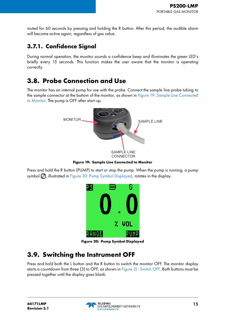
3.8. Probe Connection and UseThe monitor has an internal pump for use with the probe. Connect the sample line probe tubing tothe sample connector at the bottom of the monitor, as shown in Figure 19: Sample Line Connectedto Monitor. The pump is OFF after start-up.
Figure 19: Sample Line Connected to Monitor
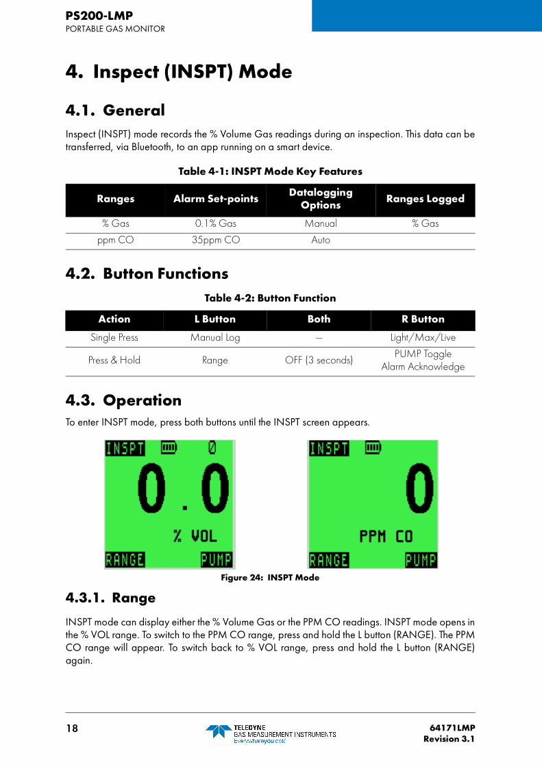
Press and hold the R button (PUMP) to start or stop the pump. When the pump is running, a pumpsymbol , illustrated in Figure 20: Pump Symbol Displayed, rotates in the display.
Figure 20: Pump Symbol Displayed
3.9. Switching the Instrument OFFPress and hold both the L button and the R button to switch the monitor OFF. The monitor displaystarts a countdown from three (3) to OFF, as shown in Figure 21: Switch OFF. Both buttons must bepressed together until the display goes blank.

16 64171LMPRevision 3.1
PS200-LMPPORTABLE GAS MONITOR
Figure 21: Switch OFF
The audible alarm sounds every second to alert user that the monitor is switching OFF.
3.10. ModesThe monitor has 3 modes of operation:
1. Inspection (INSPT)
2. Personal Surveyor (PS)
3. Purge
3.10.1. Building Identification Number (BIN)
At the end of the warm-up sequence, the monitor displays the INSPECT MODE ENTER BIN screen(see Figure 22: BIN Screen).
Figure 22: BIN Screen
At this stage, before you input a BIN, you can switch between PS mode, PURGE mode, and theBIN ENTER screen by pressing both buttons simultaneously.
NOTE: You cannot enter INSPT mode until you input a valid BIN.

1764171LMPRevision 3.1
PS200-LMPPORTABLE GAS MONITOR
Once you input a BIN, you enter INSPT mode. Once entered, you cannot switch from INSPTmode to another mode.
On the BIN ENTER screen, input a BIN using the monitor's 2 buttons.
• Pressing the L button once alters each digit
• Pressing the R button once moves to the next digit of the BIN
• Pressing and holding the R button completes the BIN
3.10.2. Display
During normal user operation, the monitor will only show 1 gas reading in large font. The monitorwill indicate the current mode at the top of the display ("INSPT", "PS" or "PURGE") (see Figure 23:Display).
The LCD will indicate the press & hold button functions at the bottom of the display.
Figure 23: Display
NOTE: Single press button functions are not shown on the display.
18 64171LMPRevision 3.1
PS200-LMPPORTABLE GAS MONITOR
4. Inspect (INSPT) Mode
4.1. GeneralInspect (INSPT) mode records the % Volume Gas readings during an inspection. This data can betransferred, via Bluetooth, to an app running on a smart device.
4.2. Button Functions
4.3. OperationTo enter INSPT mode, press both buttons until the INSPT screen appears.
Figure 24: INSPT Mode
4.3.1. Range
INSPT mode can display either the % Volume Gas or the PPM CO readings. INSPT mode opens inthe % VOL range. To switch to the PPM CO range, press and hold the L button (RANGE). The PPMCO range will appear. To switch back to % VOL range, press and hold the L button (RANGE)again.
Table 4-1: INSPT Mode Key Features
Ranges Alarm Set-points Datalogging Options Ranges Logged
% Gas 0.1% Gas Manual % Gas
ppm CO 35ppm CO Auto
Table 4-2: Button Function
Action L Button Both R Button
Single Press Manual Log — Light/Max/Live
Press & Hold Range OFF (3 seconds)PUMP Toggle
Alarm Acknowledge
1964171LMPRevision 3.1
PS200-LMPPORTABLE GAS MONITOR
4.3.2. Alarms
Both the % VOL and PPM CO ranges have alarms. The default factory settings are:
• 0.1% VOL
• 35ppm CO
4.3.3. Pump
When the monitor enters INSPT mode, the pump is automatically on, and the pump icon is presentin the upper, right-hand corner of the LCD. To turn the pump off, press and hold the R button. Thepump icon will disappear, indicating that the pump is off. Press and hold the R button again to turnthe pump back on. The pump icon reappears.
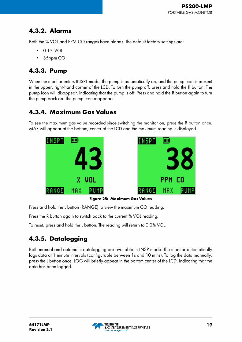
4.3.4. Maximum Gas Values
To see the maximum gas value recorded since switching the monitor on, press the R button once.MAX will appear at the bottom, center of the LCD and the maximum reading is displayed.
Figure 25: Maximum Gas Values
Press and hold the L button (RANGE) to view the maximum CO reading.
Press the R button again to switch back to the current % VOL reading.
To reset, press and hold the L button. The reading will return to 0.0% VOL.
4.3.5. Datalogging
Both manual and automatic datalogging are available in INSP mode. The monitor automaticallylogs data at 1 minute intervals (configurable between 1s and 10 mins). To log the data manually,press the L button once. LOG will briefly appear in the bottom center of the LCD, indicating that thedata has been logged.

20 64171LMPRevision 3.1
PS200-LMPPORTABLE GAS MONITOR
Figure 26: Datalogging Indicator
INSPT mode logs following data for both % VOL and PPM CO:
• Monitor Serial Number
• ON Time/Date
• BIN
• Last Cal Date
• Cal Due date
• Soundness Check result
• Pump status
• Max Reading: % Gas
• Auto Log Readings: % Gas
• Manual log Readings: % Gas
• OFF Time/Date
The data logged in INSPT mode can be uploaded to applications running on tablets (refer toSection 7. BLUETOOTH).
NOTE: Readings for both % VOL and PPM CO will be recorded regardless of therange currently displayed.

2164171LMPRevision 3.1
PS200-LMPPORTABLE GAS MONITOR
5. Personal Surveyor (PS) Mode
5.1. GeneralPersonal Surveyor (PS) mode alerts the user to the presence of flammable gas and/or carbonmonoxide while carrying out normal plumbing duties.
5.2. Button Functions
5.3. OperationTo enter PS mode, press both buttons until the PS screen appears.
Figure 27: PS Mode
5.3.1. Range
PS Mode can display either the % Volume Gas or PPM CO readings. PS Mode opens in the %VOL range.
To switch to the PPM CO range:
1. Press and hold the L button. The PPM CO range will appear.
2. To switch back to % VOL range, press and hold the L button again.
Ranges Alarm Set-points DataloggingOptions Ranges Logged
% Gas 0.1% Gas Manual % Gas
ppm CO 35ppm CO Auto ppm CO
Action L Button Both R Button
Single Press Manual Log Change Modes Light/Max/Live
Press & Hold Range OFF (3 seconds)PUMP Toggle
Alarm Acknowledge

22 64171LMPRevision 3.1
PS200-LMPPORTABLE GAS MONITOR
5.3.2. Alarms
Both the % VOL and PPM CO ranges have alarms. The default factory settings are:
• 0.1% VOL
• 35ppm CO
5.3.3. Pump
When the monitor enters PS Mode, the pump is automatically on, and the pump icon is present inthe upper, right-hand corner of the LCD.
To turn the pump off:
1. Press and hold the R button. The pump icon will disappear, indicating that the pump is off.
2. Press and hold the R button again to turn the pump back on. The pump icon reappears.
5.3.4. Maximum Gas Values
To see the maximum gas value recorded since switching the monitor on:
1. Press the R button once. MAX will appear at the bottom, center of the LCD and the maximumreading is displayed.
Figure 28: Maximum Gas Values
2. Press and hold the L button (RANGE) to view the maximum CO reading.
3. Press the R button again to switch back to the current % VOL reading.
4. To reset, press and hold the L button. The reading will return to 0.0% VOL.
5.3.5. Datalogging
Both manual and automatic datalogging are available in PS mode. The monitor automaticallylogs data at 1 minute intervals (configurable between 1s and 10 mins).
Caution: Alarm set-points are preset at the factory. Do not attempt toalter the ALARMS settings.

2364171LMPRevision 3.1
PS200-LMPPORTABLE GAS MONITOR
To log the data manually, press the L button once. LOG will briefly appear in the bottom center ofthe LCD, indicating that the data has been logged.
Figure 29: Datalogging Indicator
The following data is logged in PS mode:
• Monitor serial number
• Mode entered time/ date
• Cal Due date
• Soundness check result
• Pump status
• Max readings: % Gas, ppm CO
• Alarm set-points: %Gas, ppm CO
• Alarms activated:
– Time/Date
– Readings for alarm range
• Auto log readings: % Gas, ppm CO
• Manual log readings: % Gas, ppm CO
• OFF time/date
NOTE: Readings for both % VOL and PPM CO will be recorded regardless of therange currently displayed.
24 64171LMPRevision 3.1
PS200-LMPPORTABLE GAS MONITOR
6. PURGE Mode
6.1. GeneralPURGE mode is intended for natural gas-to-air or air-to-natural gas applications (i.e. directpurging).
6.2. Button Function
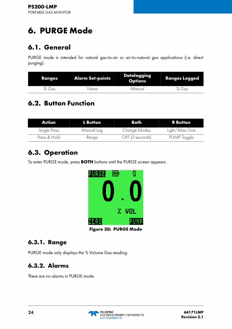
6.3. OperationTo enter PURGE mode, press BOTH buttons until the PURGE screen appears.
Figure 30: PURGE Mode
6.3.1. Range
PURGE mode only displays the % Volume Gas reading.
6.3.2. Alarms
There are no alarms in PURGE mode.
Ranges Alarm Set-points DataloggingOptions Ranges Logged
% Gas None Manual % Gas
Action L Button Both R Button
Single Press Manual Log Change Modes Light/Max/Live
Press & Hold Range OFF (3 seconds) PUMP Toggle

2564171LMPRevision 3.1
PS200-LMPPORTABLE GAS MONITOR
6.3.3. Pump
When the monitor enters PURGE mode, the pump is automatically on, and the pump icon ispresent in the upper, right-hand corner of the LCD.
To turn the pump off:
1. Press and hold the R button. The pump icon will disappear, indicating that the pump is off.
2. Press and hold the R button again to turn the pump back on. The pump icon reappears.
6.3.4. Maximum Gas Values
To see the maximum gas value recorded since switching the monitor on:
1. Press the R button once. MAX will appear at the bottom, center of the LCD and the maximumreading is displayed.
Figure 31: Maximum Gas Values
2. To reset, press and hold the L button. The reading will return to 0.0% VOL.
6.3.5. Datalogging
Only manual datalogging is available in PURGE mode. To log the data, press the L button once.LOG will briefly appear in the bottom center of the LCD, indicating that the data has been logged.
Figure 32: Datalogging Indicator

26 64171LMPRevision 3.1
PS200-LMPPORTABLE GAS MONITOR
PURGE mode logs only the % Gas range.
The following data is logged in PURGE mode:
• Monitor serial number
• Mode entered, time, & date
• CAL DUE date
• Soundness Check result
• Pump status
• Max readings: % Gas
• Manual log readings: % Gas
• OFF time & date

2764171LMPRevision 3.1
PS200-LMPPORTABLE GAS MONITOR
7. Bluetooth
7.1. GeneralThe PS200-LMP communicates Inspect Mode (INSPT) data to the utility apps using Bluetooth BLE5.0.
The monitor will indicate during warm-up if there are any completed inspections to be transferredto the tablet application.
Figure 33: Completed Inspections Ready to be Transferred
7.2. Bluetooth (BT) Connection
7.2.1. Establishing Bluetooth Communications
Bluetooth pairing is only possible during the instrument warm-up sequence (approximately 30seconds). If Bluetooth communications are not established during warm-up, they will not bepossible during the current instrument session.
If a tablet running the appropriate application is held close to the monitor during warmup, they willautomatically connect. No action is required by the user. Once the monitor establishes Bluetoothcommunications, the bottom line of the display will indicate CONNECTED as shown in Figure 34:Bluetooth Connection Notification.
NOTE: Bluetooth range is 3' (1m).

28 64171LMPRevision 3.1
PS200-LMPPORTABLE GAS MONITOR
Figure 34: Bluetooth Connection Notification
CONNECTED will remain on the bottom line during warm-up, while a BT connection is active. Ifwarm-up finishes and the Bluetooth transfer is still in progress, then the last warm-up screen ismaintained until the Bluetooth is disconnected (see Figure 35: Bluetooth Connection Notification,cont.).
Figure 35: Bluetooth Connection Notification, cont.
The app running on the smart phone/tablet controls the data transfer. When it is complete, it willdisconnect from the monitor. Several seconds later (up to 20 seconds), CONNECTED disappearsfrom monitor’s display, and the monitor continues as normal from the end of warm-up (i.e. theINSPECT MODE ENTER BIN screen).
Figure 36: BIN Screen

2964171LMPRevision 3.1
PS200-LMPPORTABLE GAS MONITOR
8. Recharging the Batteries
8.1. GeneralUse only Company approved chargers to recharge monitor.
Recharge the battery in the following situations:
• The low battery icon appears on the display.
• The monitor will not switch ON.
When the low battery icon appears on the display, approximately 30 minutes of operationat normal temperatures remain. The monitor will then switch OFF automatically.
8.2. Recharge Monitor Using the Charging / Comms Clip1. Connect the supplied charging/comms clip to the monitor. To ensure the contact nodes on the
charging/comms clip engage the monitor’s contact pads, slide the locking tongue on thecharging/comms clip fully into the monitor’s locating slot and ensure the locking pins on thecharging/comms clip firmly click into the monitor’s locking pin slots (refer to Figure 37:Charging/Comms Clip Connection).
WARNING: ONLY CHARGE THE BATTERY IN A NON-HAZARDOUSAREA.
Caution: Switch the monitor off when charging the internal battery.

30 64171LMPRevision 3.1
PS200-LMPPORTABLE GAS MONITOR
Figure 37: Charging/Comms Clip Connection
2. Connect the supplied MINI-USB to USB Cable to the Charging/Comms Clip.
Figure 38: Connect Cable to Charging/Comms Clip

3164171LMPRevision 3.1
PS200-LMPPORTABLE GAS MONITOR
3. Connect the other end of the charging cable to the USB Power adapter (or suitable USBsocket).
Figure 39: Connect Cable to USB Power Adapter
4. When charging is in process, the battery symbol and the word CHARGING flash in thedisplay.
5. When charging is complete, the full battery symbol and the word CHARGED are dis-played.
6. Disconnect from the power source.
7. To remove the charging/comms clip, pull up and back on the charging/comms clip’s releasetab and firmly pull it away from the monitor.
Figure 40: Removing the Charging/Comms Clip
NOTE: It will not damage the monitor to leave it connected to the charger.

32 64171LMPRevision 3.1
PS200-LMPPORTABLE GAS MONITOR
9. Operator Maintenance
9.1. Cleaning
Only use a moist, non-abrasive cloth to clean the outer, impact-resistant casing of the monitor. Rubthe cloth over the outer casing to remove any dirt and grime. In extreme cases, use a mild soapsolution with a non-abrasive cloth to remove any stubborn marks.
9.2. Replace Instrument FiltersThe monitor has 2 filters:
• hydrophobic (water) filter - located behind the filter cover on the front face of the monitor;• sample inlet (dust) filter - located in the sample inlet connector at the bottom of the monitor.
Inspect these filters periodically for contamination or damage.
9.2.1 Replacing the Hydrophobic (Water) Filter
Figure 41: Hydrophobic Filter Replacement
1. Using a No. 1 Pozidriv® screwdriver, unscrew the screw.
2. Slide the filter cover away from the display until the locating lugs disengage from the locatingslots.
3. Lift the cover away from the monitor.
4. Remove the hydrophobic filter.
Caution: Do not use polishes that contain silicon or solvent to clean themonitor as these may damage the flammable gas sensor (if fitted). Donot use abrasive chemicals or strong, volatile chemical solutions asthese could damage the impact-resistant casing.

3364171LMPRevision 3.1
PS200-LMPPORTABLE GAS MONITOR
5. Insert a new hydrophobic filter.
6. Place the filter cover over the recess and slide it towards the display until the locating lugsengage in the locating slots.
7. .Using a No. 1 Pozidriv® screwdriver, tighten the screw.
9.2.2 Replacing the Sample Inlet (Dust) Filter
Figure 42: Replacing the Sample Inlet (Dust) Filter
1. Using a No.1 Pozidriv® screwdriver, remove the 2 Pozi Pan screws.
2. Remove the nozzle. The sample inlet filter is located at the rear of the inlet nozzle.
3. Push a matchstick, or similar, into the front of the inlet nozzle and remove the sample inlet filterfrom the rear of the inlet nozzle.
4. Insert a new sample inlet filter into the rear of the inlet nozzle. Ensure the “rough” surface facesthe inlet filter (sample side).
5. Fit the inlet nozzle. The inlet nozzle will only fit in one direction.
6. Using a No.1 Pozidriv® screwdriver, insert the 2 Pozi Pan screws.
Note: Make sure that the locating pegs in the monitor filter recess align with themating pinholes in the hydrophobic filter.
Note: Do not overtighten the screw.
Note: Do not overtighten the screw.

34 64171LMPRevision 3.1
PS200-LMPPORTABLE GAS MONITOR
10. Calibration
10.1. General DescriptionThe monitor has been calibrated for particular gases. Where any doubt exists the product shouldbe returned to the Company or an authorized distributor for calibration.
10.2. Automatic CalibrationThe Automatic Bump/Calibration Station, shown in Figure 43: PS200-LMP Auto/BumpCalibration Station, provides controlled delivery of gases permitting users to bump test andcalibrate the monitor in a controlled manner whilst maintaining a record of calibration results.
For further details contact the Company or an authorized distributor.
Figure 43: PS200-LMP Auto/Bump Calibration Station
10.3. Calibration Validity The monitor’s calibration interval is 30 days.
Calibration validity remains the responsibility of the user.
WA RN I NG : T H E I N ST R U M E NT M U S T B E C AL I B R AT ED AN DCONFIGURED BY AUTHORIZED PERSONNEL ONLY.

3564171LMPRevision 3.1
PS200-LMPPORTABLE GAS MONITOR
11. Accessories
Part Number Description
64135LMP PS200LMP (c/w %Gas, PPM CO, Probe, Bluetooth, rubber boot)
Part Number Description
64084 Sample Inlet Filter (Instrument)
64254 Hydrophobic Filter (Instrument)
64255 Pump Assembly
66750CC % Vol. Gas Sensor
67176 CO Sensor
Part Number Description
10077 Cotton Filters - box of 10 (Probe)
12358 Hydrophobic Filter (Probe)
64109 Probe (c/w filters and tubing)
66045 Tygon Tubing Connector
66118 Tygon Tubing
Part Number Description
64172LMP Quick Operating Instructions
64247 Universal Power Plug (Mains - USB)
64260 USB Charging/Comms Clip
64303BU Rubber Boot (blue)
Part Number Description
64138 5-Way Charger
64248 In-Vehicle Charging Adapter (12V/24V - USB)
64491 In-Vehicle Charging Cradle
Part Number Description
64053 Automatic Bump & Calibration Station (Air, 2 Gas, Exhaust)
99118 On Demand Flow Regulator

36 64171LMPRevision 3.1
PS200-LMPPORTABLE GAS MONITOR
Appendix A. Typical Operating Parameters
Gas Sensor Type Range Resolution Accuracy
% VOL Gas (Natural Gas)
Catalytic/ThermalConductivity
0 to 100% 0.1% ±3%
Carbon Monoxide (CO) Electrochemical0 to
1000ppm1ppm
±10%(of indication)
Physical PropertiesDimensions (H x W x D):
4.8” x 2.3” x 1.3” (121mm x 59mm x 32mm)
Weight: 8 oz. (230 g)
EnvironmentOperatingTemperature Limits:
-4ºF to +122ºF (-20ºC to +65ºC)
Storage TemperatureLimits:
-40ºF to +149ºF (-40ºC to +65ºC)
Humidity: 0 to 95% R.H non-condensing
Typical Flow RateInformation:
Nominal pump flow rate is 0.132 to 0.185 gals./min. (0.5 to 0.7 liters/min.)Max. 97 ft. (30m) sample line.Typ. flow fail rate = 0.026 to 0.053 gals./min. (0.1 to 0.2 liters/min.)
Response Times
Vol GasT50: <10s (CSA 22.2 No. 152)T60: <12s (ANSI 12.13.01)
CO T90: <20s
Warm-up/Stabilization Time<40 seconds
AlarmsHighly visible, flashing LED; piercing >90dB audible
DisplayGreen/Red LCD backlit display
Power SourceBattery: Rechargeable Lithium-Ion
Runtime: Up to 24 hours (12 hours pumped)
Charging Time: Up to 4 hours
ConstructionHigh-impact, rubberized polycarbonate case
IP RatingIP67

3764171LMPRevision 3.1
PS200-LMPPORTABLE GAS MONITOR
Natural Gas MeasurementsThe monitor is used to accurately measure natural gas. The accuracy is ±3% of reading when thenatural gas composition is as follows:
Methane (CH4): ≥ 90%
Ethane (C2H6): ≤ 5%
Propane (C3H8): ≤ 1.4%
Butane (C4H10): ≤ 0.5%
Inert gas (e.g.Nitrogen (N2)): ≤ 3%

38 64171LMPRevision 3.1
PS200-LMPPORTABLE GAS MONITOR
Appendix B. Setting the Date and TimeThe monitor’s DATE and TIME are automatically corrected when connected to Tablets. Accessingthe Configuration Menu Mode allows the user to manually alter the monitor’s date and time.
B.1. Accessing the Configuration Menu Mode1. Press and hold the R button for one second to switch the monitor ON.
2. As soon as the monitor identification display appears (see Figure 4: Monitor Identification Dis-play), press the following buttons in sequence:
– L button
– R button
– L button
– R button
The monitor will continue through its warm-up sequence, which takes approximately 30 seconds.A countdown timer appears in the upper, right-hand corner of the LCD during the warm-upsequence. If you pressed the correct button sequence, the timer will alternate with the letter M (forMenu).
B.2. Configuration Menu ScreenWhen entered correctly, a sub-menu appears detailing four headings (see Figure 47: MenuScreen):
• NORMAL
• ALARMS
• DEFAULT
• CLOCK
Figure 47: Menu Screen
Caution: NORMAL and CLOCK are the only two options the usershould enter. Do not attempt to alter the ALARMS or DEFAULT settings.

3964171LMPRevision 3.1
PS200-LMPPORTABLE GAS MONITOR
Press the L button to move between menu options. Press the R button once to enter a menu option.Press and hold the R button to exit the menu and return to normal operation.
B.2.1. Normal
Pressing NORMAL returns the monitor to normal operation.
B.2.2. Clock
Pressing CLOCK opens the EDIT DATE AND TIME screen (see Figure 48: EDIT DATE AND TIMEScreen). To change date and time:
1. Press ALTER to change the flashing parameter.
2. Press ACCEPT to advance to the next parameter.
3. Once you have input the desired time and date, press and hold the R button to return to themenu screen.
Figure 48: EDIT DATE AND TIME Screen

PS200-LMPPORTABLE GAS MONITOR
40 64171LMPRevision 3.1
Appendix C. Technical SupportThis product is designed to provide you with reliable, trouble-free service. Contact your regionaltechnical support if you have technical questions, need support, or if you need to return a product.Details can be found at:
www.teledynegasandflamedetection.com
Note: When returning a product, contact Technical Support to obtain a ReturnMaterialAuthorization (RMA) number prior to shipping.

PS200-LMPPORTABLE GAS MONITOR
4164171LMPRevision 3.1
This page is intentionally left blank.

User Guide
AMERICAS EMEA ASIA PACIFIC
4055 Technology Forest Blvd.The WoodlandsTX 77381, USATel.: +1-713-559-9200
Inchinnan Business ParkRenfrew, PA4, 9RGScotland, UKTel.: +44 (0) 141 812 3211
290 Guigiao RoadPudang, Shanghai 201206People’s Republic of ChinaTel.: +86-21-3127-6373
www.teledynegasandflamedetection.com
64171LMP Revision 3.1
Copyright © 2020 Teledyne Gas and Flame Detection. All rights reserved.