pert3 phoenix user manual - teledyne...
TRANSCRIPT
PeRT3 Phoenix System
User Manual
921515 rev A
August 2013

Teledyne LeCroy PeRT3 Phoenix System User Manual ii
© 2012 Teledyne LeCroy, Inc. All rights reserved. Unauthorized duplication of Teledyne LeCroy documentation materials other than for internal sales and distribution purposes is strictly prohibited. However, clients are encouraged to distribute and duplicate Teledyne LeCroy documentation for their own internal educational purposes.
PeRT3 and Teledyne LeCroy are registered trademarks of Teledyne LeCroy, Inc. Windows is a registered trademark of Microsoft Corporation. Other product or brand names are trademarks or requested trademarks of their respective holders. Information in this publication supersedes all earlier versions. Specifications are subject to change without notice.
Warranty
THE WARRANTY BELOW REPLACES ALL OTHER WARRANTIES, EXPRESSED OR IMPLIED, INCLUDING BUT NOT LIMITED TO ANY IMPLIED WARRANTY OF MERCHANTABILITY, FITNESS, OR ADEQUACY FOR ANY PARTICULAR PURPOSE OR USE. TELEDYNE LECROY SHALL NOT BE LIABLE FOR ANY SPECIAL, INCIDENTAL, OR CONSEQUENTIAL DAMAGES, WHETHER IN CONTRACT OR OTHERWISE. THE CUSTOMER IS RESPONSIBLE FOR THE TRANSPORTATION AND INSURANCE CHARGES FOR THE RETURN OF PRODUCTS TO THE SERVICE FACILITY. TELEDYNE LECROY WILL RETURN ALL PRODUCTS UNDER WARRANTY WITH TRANSPORT PREPAID.
The PeRT3 is warranted for normal use and operation, within specifications, for a period of three years from shipment. Teledyne LeCroy will either repair or, at our option, replace any product returned to one of our authorized service centers within this period. However, in order to do this we must first examine the product and find that it is defective due to workmanship or materials and not due to misuse, neglect, accident, or abnormal conditions or operation.
Teledyne LeCroy shall not be responsible for any defect, damage, or failure caused by any of the following: a) attempted repairs or installations by personnel other than Teledyne LeCroy representatives or b) improper connection to incompatible equipment, or c) for any damage or malfunction caused by the use of non‐Teledyne LeCroy supplies. Furthermore, Teledyne LeCroy shall not be obligated to service a product that has been modified or integrated where the modification or integration increases the task duration or difficulty of servicing the instrument. Spare and replacement parts, and repairs, all have a 90‐day warranty.
The instrument's firmware has been thoroughly tested and is presumed to be functional. Nevertheless, it is supplied without warranty of any kind covering detailed performance. Products not made by Teledyne LeCroy are covered solely by the warranty of the original equipment manufacturer.
921515 revA August 2013
Teledyne LeCroy PeRT3 Phoenix System User Manual 11
Contents
Chapter 1: Safety Instructions ...............................................................................7
Symbols ......................................................................................................................................... 7
Precautions ................................................................................................................................... 7
Operating Environment ................................................................................................................ 8
Cooling .......................................................................................................................................... 8
Cleaning......................................................................................................................................... 8
Calibration ..................................................................................................................................... 9
Power ............................................................................................................................................. 9
Power Consumption........................................................................................................................................9
8-BIT MODELS: ................................................................................................................................ .......................... 9
12-BIT MODELS: .............................................................................................................................. .......................... 9
Power and Ground Connections....................................................................................................................9
Standby Power...............................................................................................................................................10
Chapter 2: Overview..............................................................................................11
System Configurations .............................................................................................................. 12
Software Test Suites .....................................................................................................................................12
Upgrades and Maintenance ..........................................................................................................................13
Connection to Device Under Test ................................................................................................................13
Chapter 3: Quick Start Guide ...............................................................................15
Introduction ................................................................................................................................. 15
Requirements for the Host Machine ............................................................................................................16
Front Panel Connections ..............................................................................................................................16
Back Panel Connections...............................................................................................................................17
Initial System Setup ......................................................................................................................................17
Connecting to the PeRT3 Phoenix ...............................................................................................................19
Overview of Connection ................................................................................................................. ........................ 19
Steps to Connect ............................................................................................................................. ........................ 20
Teledyne LeCroy Contents
2 Teledyne LeCroy PeRT 3 Phoenix System User Manual
Main Tab ........................................................................................................................................... ........................ 21
PeRT3 Selection Panel .................................................................................................................... ........................ 22
Connecting the Device Under Test ..............................................................................................................23
Selecting and Running a Test ......................................................................................................................24
Modifying a Test ............................................................................................................................................26
Testing a DUT ................................................................................................................................................26
Run Test Scripts ............................................................................................................................................31
Run Test Patterns ............................................................................................................................ ........................ 32
Chapter 4: Basic Principles of Operation ........................................................... 33
Introduction of Stress into Waveform ...................................................................................... 34
De-Emphasis and Pre-shoot.........................................................................................................................34
Random Jitter ................................................................................................................................................35
Periodic Jitter .................................................................................................................................. ........................ 36
Differential Mode Noise .................................................................................................................. ........................ 36
Common Mode Noise ...................................................................................................................... ........................ 37
Chapter 5: Software Overview ............................................................................. 39
Starting the PeRT3 Program...................................................................................................... 39
Main Application Window .......................................................................................................... 40
Main Library Window.................................................................................................................. 41
File Menu ..................................................................................................................................... 42
New .................................................................................................................................................................43
Import... ..........................................................................................................................................................43
Export... ..........................................................................................................................................................44
Print ................................................................................................................................................................45
Exit ..................................................................................................................................................................45
Chapter 6: Manual Testing ................................................................................... 47
System Control Ribbon - Main Tab ........................................................................................... 47
Master Controls .............................................................................................................................................47
PeRT3 Selection ............................................................................................................................................48
Configuration .................................................................................................................................................49
Protocol: ........................................................................................................................................... ........................ 49
Speed: .............................................................................................................................................. ........................ 49
SSC: .................................................................................................................................................. ........................ 50
Clock Out: ........................................................................................................................................ ........................ 50
DUT Initialization ...........................................................................................................................................50
DUT Status .....................................................................................................................................................52
System Control Ribbon -- Channel Tabs.................................................................................. 52
Master Controls .............................................................................................................................................53
Contents Teledyne LeCroy
Teledyne LeCroy PeRT 3 Phoenix System User Manual 3
Signal Generation and Introduction of Distortion ......................................................................................53
Overview of Signal Impairment Controls ...................................................................................... ........................ 53
Signal ................................................................................................................................................ ........................ 57
De-Emphasis .................................................................................................................................... ........................ 57
Random Jitter .................................................................................................................................. ........................ 58
High Frequency Sinusoidal Jitter .................................................................................................. ........................ 59
Low Frequency Sinusoidal Jitter ................................................................................................... ........................ 59
Pattern/Termination ........................................................................................................................ ........................ 60
Eye Preview ..................................................................................................................................... ........................ 62
System Control Ribbon -- Analysis Tab ................................................................................... 62
System Control Ribbon -- Pattern Tab...................................................................................... 63
System Control Ribbon -- Options Tab .................................................................................... 63
Default Settings .............................................................................................................................................63
Pattern Checking ...........................................................................................................................................63
External Options ............................................................................................................................................64
Rx DFE ............................................................................................................................................................65
External Jitter.................................................................................................................................................66
Clock Out........................................................................................................................................................66
Diagnostics ....................................................................................................................................................66
View ................................................................................................................................................................67
Chapter 7: Main Library Window ......................................................................... 69
Main Library Toolbar Buttons .....................................................................................................................70
The Filter Function ........................................................................................................................................71
Chapter 8: Creating a New Test Script ................................................................ 73
Editing an Existing Script: ............................................................................................................................74
Starting a New Test Script ......................................................................................................... 75
Test Script Data Block................................................................................................................ 76
Basic Data ......................................................................................................................................................77
Test Description ............................................................................................................................................77
Device Description ........................................................................................................................................77
Building a Test Script Block-by-Block...................................................................................... 78
Reset/ Initialize Block ................................................................................................................. 78
Setup...............................................................................................................................................................78
Initialization ....................................................................................................................................................79
Automation.....................................................................................................................................................79
Receiver Test Case Block .......................................................................................................... 80
Adding, Inserting and Deleting Test Cases.............................................................................. 80

Teledyne LeCroy Contents
4 Teledyne LeCroy PeRT 3 Phoenix System User Manual
Chapter 9: Creating Test Patterns ....................................................................... 83
Creating a New Test Pattern ...................................................................................................... 83
Pattern Editor Tab Controls..........................................................................................................................85
Master Controls ............................................................................................................................... ........................ 85
Display Mode ................................................................................................................................... ........................ 85
Standard Edit ................................................................................................................................... ........................ 87
Pattern Edit ...................................................................................................................................... ........................ 87
Import/Export ................................................................................................................................... ........................ 88
View Info ........................................................................................................................................... ........................ 88
Notifications ...................................................................................................................................................88
Adding Frames to Patterns...........................................................................................................................89
Adding Data to Patterns................................................................................................................................91
Modifying Data Within a Pattern ..................................................................................................................92
Chapter 10: Analysis and Reports....................................................................... 93
System Control Ribbon -- Analysis Tab ................................................................................... 93
Master Controls .............................................................................................................................................94
Graph Type.....................................................................................................................................................94
Graph Axes ....................................................................................................................................................94
Data Ch1-4 ......................................................................................................................................................95
Signal Parameters .........................................................................................................................................95
Tools ...............................................................................................................................................................96
Analysis Graph Types ................................................................................................................ 96
Log View .........................................................................................................................................................97
Spreadsheet View ..........................................................................................................................................98
Errors vs. Time ..............................................................................................................................................99
Single Parameter .........................................................................................................................................100
Multi Single Parameter ................................................................................................................................101
Scatter Chart ................................................................................................................................................101
Adding a Spec Line in a Chart ....................................................................................................... ...................... 102
Chapter 11: Control of Screen Appearance...................................................... 103
Customizing the Quick Access Toolbar ................................................................................. 103
Quick Access Toolbar Buttons .................................................................................................................104
The System Control Ribbon .................................................................................................... 107
Customizing the Main Library and Output Windows ............................................................ 108
Selecting the Style Color Theme............................................................................................. 110
Contents Teledyne LeCroy
Teledyne LeCroy PeRT 3 Phoenix System User Manual 5
Appendix A: Certifications ................................................................................. 111
EMC Compliance ...................................................................................................................... 111
EC DECLARATION OF CONFORMITY - EMC ............................................................................................111
Electromagnetic Emissions: .......................................................................................................... ...................... 111
Electromagnetic Immunity: ............................................................................................................ ...................... 111
European Contact: .......................................................................................................................... ...................... 112
AUSTRALIA & NEW ZEALAND DECLARATION OF CONFORMITY - EMC .............................................112
Australia / New Zealand Contacts: ................................................................................................ ...................... 112
Safety Compliance.................................................................................................................... 112
EC DECLARATION OF CONFORMITY - LOW VOLTAGE .........................................................................112
U.S. NATIONALLY RECOGNIZED AGENCY CERTIFICATION .................................................................113
CANADIAN CERTIFICATION.......................................................................................................................113
Environmental Compliance ..................................................................................................... 113
END-OF-LIFE HANDLING ................................................................................................................ ...................... 113
RESTRICTION OF HAZARDOUS SUBSTANCES (ROHS) ............................................................. ...................... 114
ISO Certification ..........................................................................................................................................114
Appendix B: Contact Teledyne LeCroy............................................................. 115
How to Contact Teledyne LeCroy ........................................................................................... 115
Index:.................................................................................................................. 117

Teledyne LeCroy Contents
6 Teledyne LeCroy PeRT 3 Phoenix System User Manual

Teledyne LeCroy PeRT3 Phoenix System User Manual 7
Chapter 1
Safety Instructions
This section contains instructions that must be observed to keep the instrument operating in a correct and safe condition. You are required to follow generally accepted safety procedures in addition to the precautions specified in this section. The overall safety of any system incorporating this instrument is the responsibility of the assembler of the system.
Symbols
These symbols appear on the instrument's front or rear panels and in its documentation to alert you to important safety considerations.
CAUTION of potential damage to instrument, or WARNING of
potential for bodily injury. Attend to the accompanying information to protect against personal injury or damage. Do not proceed until conditions are fully understood and met.
High voltage. Risk of electro‐shock.
Measurement ground connection.
Safety (protective) ground connection.
Alternating Current.
Precautions
Use proper power cord. Use only the power cord shipped with this instrument and certified for the country of use.
Maintain ground. This product is grounded through the power cord grounding conductor. To avoid electric shock, connect only to a grounded mating outlet.
Connect and disconnect properly. Do not connect/disconnect probes or test leads while they are connected to a voltage source.
8
Teledyne LeCroy Operating Environment
Observe all terminal ratings. Do not apply a voltage to any input that exceeds the maximum rating of that input. Refer to the front of the instrument for maximum input ratings.
Use only within operational environment listed. Do not use in wet or explosive atmospheres.
Use indoors only.
Keep product surfaces clean and dry.
Do not block the cooling vents. Leave a minimum six‐inch (15 cm) gap between the instrument and the nearest object. Keep the underside clear of papers and other objects.
Do not remove the covers or inside parts. Refer all maintenance to qualified service personnel.
Do not operate with suspected failures. Do not use the product if any part is damaged. Cease operation immediately and sequester the instrument from inadvertent use.
Operating Environment
Temperature: 5 to 40 °C.
Humidity: Maximum relative humidity 80% for temperatures up to 31° C decreasing linearly to 50% relative humidity at 40° C (or at the upper operational temperature limit).
Altitude: Up to 10,000 ft (3,048 m) at or below 25° C.
Cooling
The instrument relies on forced air cooling with internal fans and vents. Take care to avoid restricting the airflow to any part. Around the sides and rear, leave a minimum of 15cm (6 inches) between the instrument and the nearest object. At the bottom, the feet (up or down) provide adequate clearance.
CAUTION. Do not block cooling vents. Always keep the area beneath the instrument clear of paper and other items.
The instrument also has internal fan control circuitry that regulates the fan speed based on the ambient temperature. This is performed automatically after start‐up.
Cleaning
Clean only the exterior of the instrument using a damp, soft cloth. Do not use harsh chemicals or abrasive elements. Under no circumstances submerge the instrument or allow moisture to penetrate it. Avoid electric shock by unplugging the power cord from the AC outlet before cleaning.
CAUTION. Do not attempt to clean internal parts. Refer to qualified service personnel.

Teledyne LeCroy PeRT3 Phoenix System User Manual 9
Calibration Teledyne LeCroy
Calibration
The instrument is calibrated at the factory prior to being shipped. The recommended calibration interval is one year. Calibration should be performed by qualified personnel only.
The instrument software includes automatic and manual calibration functions.
CAUTION. It is required that all inputs be removed from the instrument prior to performing a manual calibration.
Schedule an annual factory calibration as part of your regular maintenance. Extended warranty, calibration, and upgrade plans are available for purchase. Contact your Teledyne LeCroy sales representative or [email protected] to purchase a service plan.
Power
Power Consumption
Power Consumption (Nominal): 325 Watts (325 VA)
Power and Ground Connections
The instrument is provided with a 10A/250V 18AWG rated grounded cord set containing a molded three‐terminal polarized plug and a standard IEC320 (Type C13) connector for making line voltage and safety ground connections.
The AC inlet ground is connected directly to the frame of the instrument. For adequate protection again electric shock, connect to a mating outlet with a safety ground contact.
WARNING. Interrupting the protective conductor inside or outside the instrument, or disconnecting the safety ground terminal, creates a hazardous situation. Intentional interruption is prohibited.

Teledyne LeCroy Power
10
Standby Power
The Power (Standby) button controls the operational state of the instrument. Press the button to switch the instrument On or into Standby mode (Off).
Always use the Power button to execute a proper shut down process and preserve settings before powering down.
Powering off does not disconnect the instrument from the AC power supply. The only way to fully power down the instrument is to shut down then unplug the AC power cord from the outlet. We recommend unplugging the instrument if it will be unused for a long period of time.
Teledyne LeCroy PeRT3 Phoenix System User Manual 11
Chapter 2
Overview
The Teledyne LeCroy PeRT3 Phoenix Test System is a new tool for testing of transceivers and other serial data communication devices and systems. Verifying device performance to current serial data standards normally requires multiple tools and multiple test setups, in order to test the devices over the entire range of requirements, from signal quality and BER testing through to protocol level error rate verification. With the Teledyne LeCroy
PeRT3 Phoenix, this entire process can be accomplished quickly and easily, using a single tool and a single experimental setup, on multiple lanes of a serial communication link.
The PeRT3 Phoenix System is the first “protocol enabled” transceiver tester, allowing the system to run not only electrical testing and error ratio testing, but also to control the device under test during test operation. This allows further testing under live traffic
conditions since the PeRT3 Phoenix can communicate directly with the device, generating actual traffic to exercise the device, which then can be used to measure protocol‐level error ratios.
PeRT3 stands for Protocol enabled Receiver and Transmitter Tolerance Tester.
The PeRT3 Phoenix combines the electrical test properties of jitter testers, the bit error ratio testing of BERTs, and the high level protocol packet error ratio testing of protocol exercisers. All of this is accomplished with a single system and single setup.
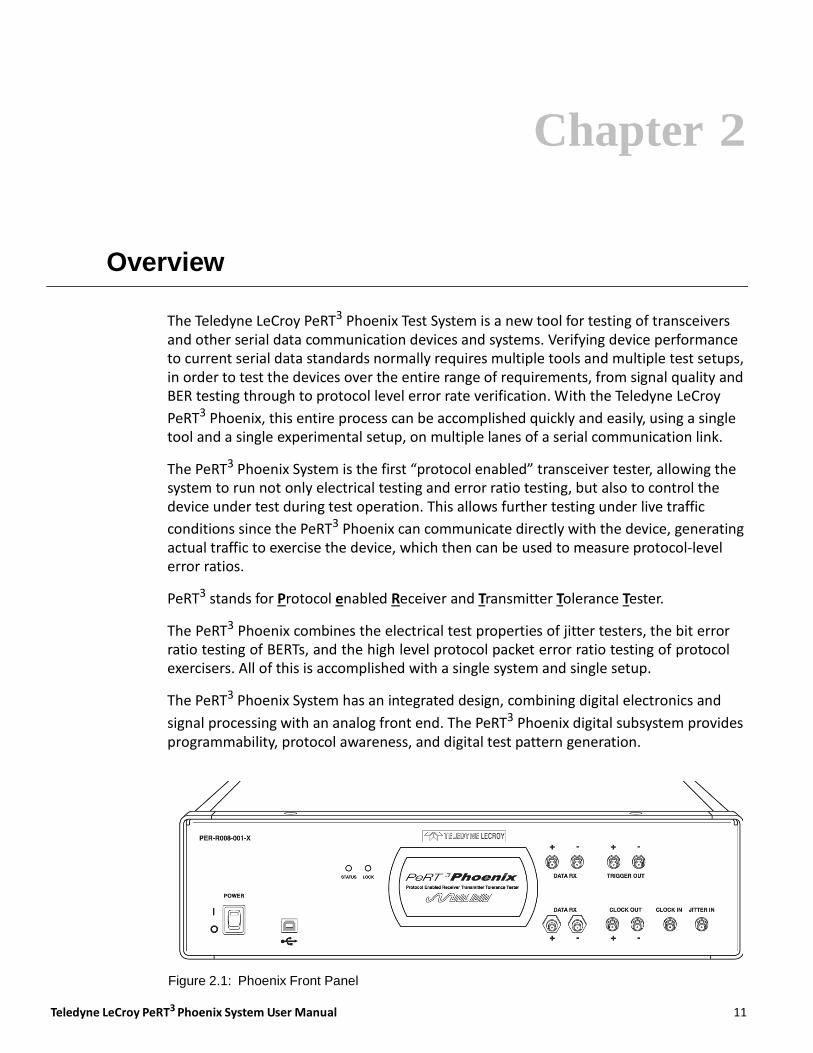
The PeRT3 Phoenix System has an integrated design, combining digital electronics and
signal processing with an analog front end. The PeRT3 Phoenix digital subsystem provides programmability, protocol awareness, and digital test pattern generation.
Figure 2.1: Phoenix Front Panel
Teledyne LeCroy System Configurations
12
The analog front end provides advanced high quality signal generation with precise timing control, and the ability to produce a controlled signal waveform with user‐ controlled jitter levels, amplitude modulation and other electrical stress generation. The analog front end superimposes these signal impairments on the outgoing signal to exercise and test the receiver channel of the device under test.
The PeRT3 Phoenix System provides the ability to control and modulate the outgoing test signal. Test capabilities include modulation of clock noise and jitter, signal shaping (such as amplitude control, rise/fall generation), pre‐ and de‐emphasis, and also the ability to monitor the signal quality of the traffic returned from the test device.
The “protocol‐enabled” capabilities of the PeRT3 Phoenix also allow the system to manage protocol‐specific issues that confuse less sophisticated test systems. An example is the resynchronization of clocks in SATA systems through the use of the ALIGN
primitives. The PeRT3 Phoenix can monitor and record protocol‐level errors such as CRC errors, and protocol‐specific errors such as R_ERR in SATA.
The PeRT3 Phoenix is able to: (1) generate patterns which produce standardized tests such as PRBS; (2) generate protocol‐level commands, which can be used both to control the device under test (e.g., to put the device into a loop‐back self‐test mode, or request information from the device on errors detected by the device); and (3) provide testing
under live traffic conditions while the PeRT3 Phoenix exercises the device under test.
The unique combination of abilities provided by the PeRT3 Phoenix allows the user, with a single system and setup, to run through an entire range of tests to verify the total performance of the device under test. The result is an economical, efficient and easy‐to‐ use system for any developer working on serial data communication designs or devices.
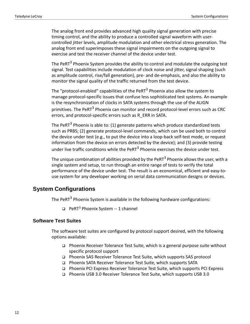
System Configurations
The PeRT3 Phoenix System is available in the following hardware configurations:
PeRT3 Phoenix System ‐‐ 1 channel
Software Test Suites
The software test suites are configured by protocol support desired, with the following options available:
Phoenix Receiver Tolerance Test Suite, which is a general purpose suite without specific protocol support
Phoenix SAS Receiver Tolerance Test Suite, which supports SAS protocol Phoenix SATA Receiver Tolerance Test Suite, which supports SATA Phoenix PCI Express Receiver Tolerance Test Suite, which supports PCI Express Phoenix USB 3.0 Receiver Tolerance Test Suite, which supports USB 3.0
Teledyne LeCroy PeRT3 Phoenix System User Manual 13
System Configurations Teledyne LeCroy
Upgrades and Maintenance
Maintenance agreements are available to provide extended support.
Note: PeRT3 Phoenix systems require calibration on an annual basis to maintain performance within factory specifications. The Teledyne LeCroy maintenance agreements normally include annual calibration of the system.
Connection to Device Under Test
The PeRT3 Phoenix provides coaxial SMA connectors to maintain signal integrity between the device under test (DUT) and the test system. A separate SMA connector is provided for each conductor in the differential pair (i.e., two connectors per line, four connectors per bi‐directional channel). The nature of the connection to the DUT will vary depending on the specifics of the DUT, but close attention must be paid to maintaining signal integrity in design and implementation of the connections.

Teledyne LeCroy PeRT3 Phoenix System User Manual 15
Chapter 3
Quick Start Guide
Introduction
The Teledyne LeCroy PeRT3 Phoenix Test System is a new tool for testing of transceivers and other serial data communication devices and systems. Verifying device performance to current serial data standards normally requires multiple tools and multiple test setups, in order to test the devices over the entire range of requirements, from signal quality and BER testing through to protocol level error rate verification. With the Teledyne LeCroy
PeRT3 Phoenix, this entire process can be accomplished quickly and easily, using a single tool and a single experimental setup, on multiple lanes of a serial communication link.
The PeRT3 Phoenix System is a “protocol enabled” transceiver tester, allowing the system to run not only electrical testing and error ratio testing, but also to control the device under test during test operation. This allows further testing under live traffic conditions
since the PeRT3 Phoenix can communicate directly with the device, generating actual traffic to exercise the device, which then can be used to measure protocol‐level error ratios.
PeRT3 stands for Protocol Enabled Receiver and Transmitter Tolerance Tester.
The PeRT3 Phoenix combines the electrical test properties of jitter testers, the bit error ratio testing of PeRTs, and the high level protocol packet error ratio testing of protocol exercisers. All of this is accomplished with a single system and single setup.
Unpacking the System
The PeRT3 Phoenix is shipped with the following components:
PeRT3 Phoenix Hardware Platform
PeRT3 System Software CD AC Power Cord USB Cable to connect host machine to PeRT3 Phoenix
Unpack the system and verify that all system components are present. If any components are missing, contact Teledyne LeCroy Service at 1‐800‐909‐7112 (or 408‐653‐1260).
16
Teledyne LeCroy Introduction
Requirements for the Host Machine
A host machine system must be supplied to work with the Phoenix system with the following minimum requirements:
Intel Pentium 4, AMD Athlon/AMD Duron, or newer compatible processor with a clock speed of at least 2 GHz.
Microsoft Windows Vista or later OS. Minimum of 1 GB of RAM. Minimum of 25 MB of free hard disk space. Additional space is required for opera‐
tion of applications and storing recorded results. Display resolution of at least 1280 x 800 with 24‐bit color depth is highly recom‐
mended. Application can be run on 800 x 600 monitor, but user experience is much better with the higher screen resolution.
USB 2.0 port.
Front Panel Connections
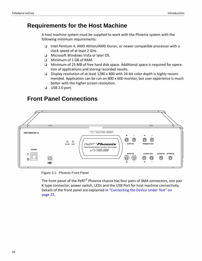
Figure 3.1: Phoenix Front Panel
The front panel of the PeRT3 Phoenix chassis has four pairs of SMA connectors, one pair K‐type connector, power switch, LEDs and the USB Port for host machine connectivity. Details of the front panel are explained in “Connecting the Device Under Test” on page 23.
Teledyne LeCroy PeRT3 Phoenix System User Manual 17
Introduction Teledyne LeCroy
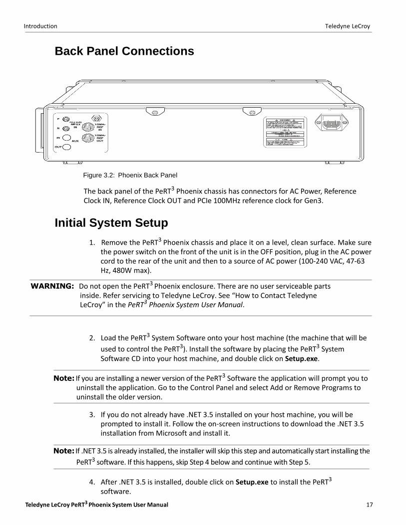
Back Panel Connections
Figure 3.2: Phoenix Back Panel
The back panel of the PeRT3 Phoenix chassis has connectors for AC Power, Reference Clock IN, Reference Clock OUT and PCIe 100MHz reference clock for Gen3.
Initial System Setup
1. Remove the PeRT3 Phoenix chassis and place it on a level, clean surface. Make sure the power switch on the front of the unit is in the OFF position, plug in the AC power cord to the rear of the unit and then to a source of AC power (100‐240 VAC, 47‐63 Hz, 480W max).
WARNING: Do not open the PeRT3 Phoenix enclosure. There are no user serviceable parts inside. Refer servicing to Teledyne LeCroy. See “How to Contact Teledyne LeCroy” in the PeRT3 Phoenix System User Manual.
2. Load the PeRT3 System Software onto your host machine (the machine that will be
used to control the PeRT3). Install the software by placing the PeRT3 System Software CD into your host machine, and double click on Setup.exe.
Note: If you are installing a newer version of the PeRT3 Software the application will prompt you to
uninstall the application. Go to the Control Panel and select Add or Remove Programs to uninstall the older version.
3. If you do not already have .NET 3.5 installed on your host machine, you will be
prompted to install it. Follow the on‐screen instructions to download the .NET 3.5 installation from Microsoft and install it.
Note: If .NET 3.5 is already installed, the installer will skip this step and automatically start installing the
PeRT3 software. If this happens, skip Step 4 below and continue with Step 5.
4. After .NET 3.5 is installed, double click on Setup.exe to install the PeRT3
software.
18
Teledyne LeCroy Introduction
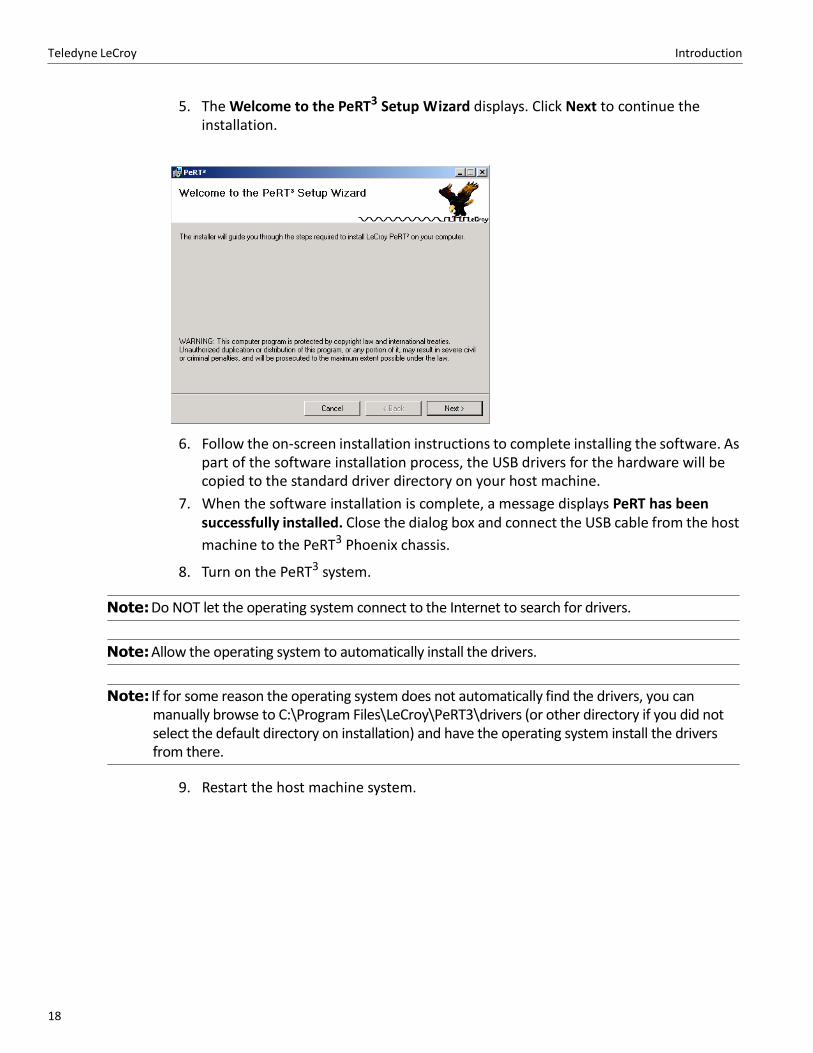
5. The Welcome to the PeRT3 Setup Wizard displays. Click Next to continue the installation.
6. Follow the on‐screen installation instructions to complete installing the software. As part of the software installation process, the USB drivers for the hardware will be copied to the standard driver directory on your host machine.
7. When the software installation is complete, a message displays PeRT has been successfully installed. Close the dialog box and connect the USB cable from the host
machine to the PeRT3 Phoenix chassis.
8. Turn on the PeRT3 system.
Note: Do NOT let the operating system connect to the Internet to search for drivers.
Note: Allow the operating system to automatically install the drivers.
Note: If for some reason the operating system does not automatically find the drivers, you can manually browse to C:\Program Files\LeCroy\PeRT3\drivers (or other directory if you did not select the default directory on installation) and have the operating system install the drivers from there.
9. Restart the host machine system.
Teledyne LeCroy PeRT3 Phoenix System User Manual 19
Introduction Teledyne LeCroy
Connecting to the PeRT3 Phoenix
Overview of Connection
The PeRT3 Phoenix System allows the user to be directly connected to the PeRT3 system in use, or connect remotely via a network. This latter method is very useful when the system is located in a lab or other remote location, and the user wishes to conduct testing from their office (or home).
To support this flexibility, the software application includes both a client, which contains the user interface displayed to the user, and a server, which communicates directly with
the PeRT3 hardware. The server must exist on the host machine directly connected to the hardware, the client may exist on any host machine that has a network connection to the
server. By default, the PeRT3 installer installs both client and server programs.
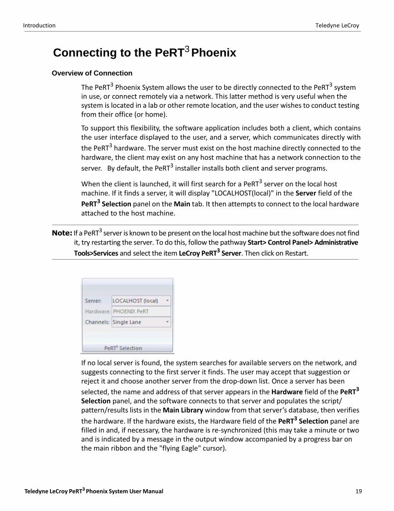
When the client is launched, it will first search for a PeRT3 server on the local host machine. If it finds a server, it will display "LOCALHOST(local)" in the Server field of the
PeRT3 Selection panel on the Main tab. It then attempts to connect to the local hardware attached to the host machine.
Note: If a PeRT3 server is known to be present on the local host machine but the software does not find it, try restarting the server. To do this, follow the pathway Start> Control Panel> Administrative
Tools>Services and select the item LeCroy PeRT3 Server. Then click on Restart.
If no local server is found, the system searches for available servers on the network, and suggests connecting to the first server it finds. The user may accept that suggestion or reject it and choose another server from the drop‐down list. Once a server has been
selected, the name and address of that server appears in the Hardware field of the PeRT3
Selection panel, and the software connects to that server and populates the script/ pattern/results lists in the Main Library window from that server’s database, then verifies
the hardware. If the hardware exists, the Hardware field of the PeRT3 Selection panel are filled in and, if necessary, the hardware is re‐synchronized (this may take a minute or two and is indicated by a message in the output window accompanied by a progress bar on the main ribbon and the "flying Eagle" cursor).
20
Teledyne LeCroy Introduction
Steps to Connect
On your host machine, launch the PeRT3 software through one of the following methods:
From the START Menu, select All Programs, then select LeCroy, then select PeRT3,
then select LeCroy PeRT3.
Double‐click on the LeCroy PeRT3 icon on your host machine desktop.
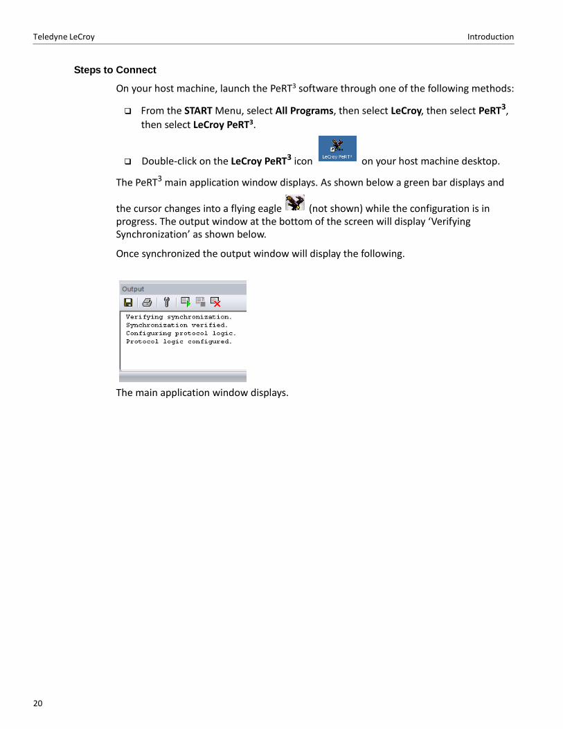
The PeRT3 main application window displays. As shown below a green bar displays and
the cursor changes into a flying eagle (not shown) while the configuration is in progress. The output window at the bottom of the screen will display ‘Verifying Synchronization’ as shown below.
Once synchronized the output window will display the following.
The main application window displays.
Teledyne LeCroy PeRT3 Phoenix System User Manual 21
Introduction Teledyne LeCroy
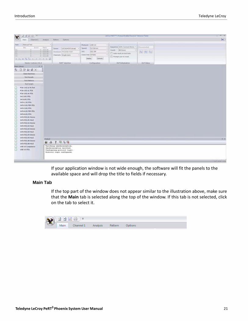
If your application window is not wide enough, the software will fit the panels to the available space and will drop the title to fields if necessary.
Main Tab
If the top part of the window does not appear similar to the illustration above, make sure that the Main tab is selected along the top of the window. If this tab is not selected, click on the tab to select it.
22
Teledyne LeCroy Introduction
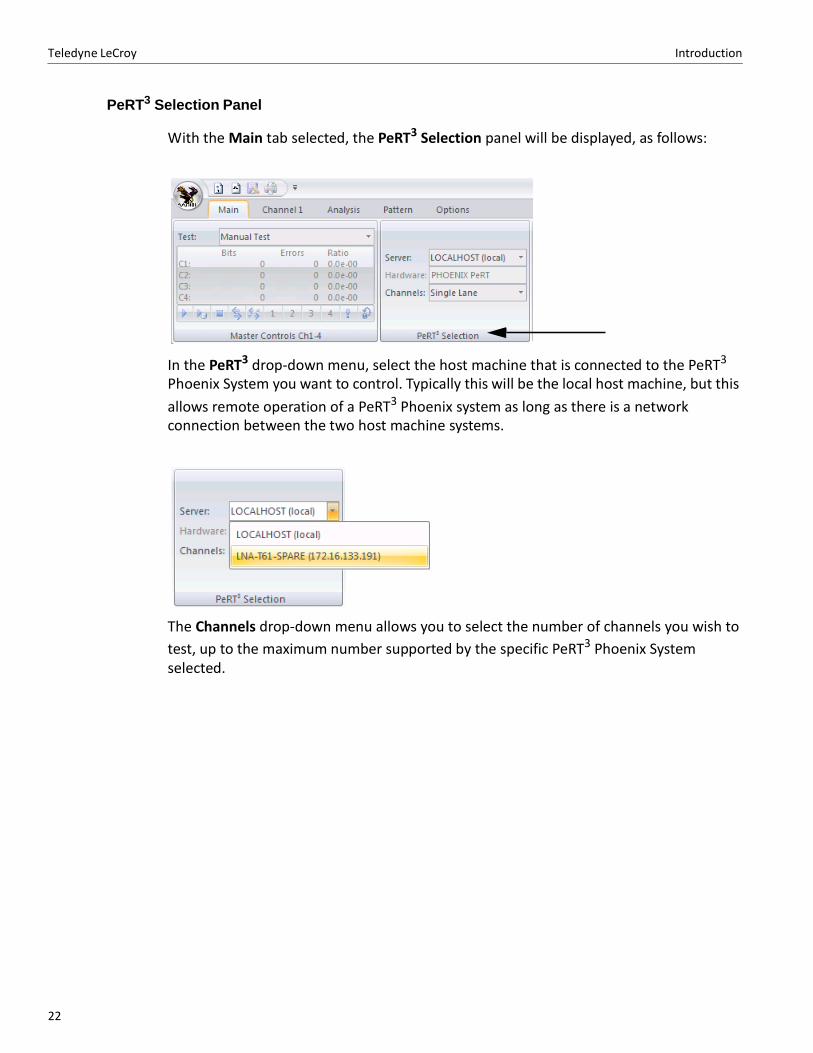
PeRT3 Selection Panel
With the Main tab selected, the PeRT3 Selection panel will be displayed, as follows:
In the PeRT3 drop‐down menu, select the host machine that is connected to the PeRT3
Phoenix System you want to control. Typically this will be the local host machine, but this
allows remote operation of a PeRT3 Phoenix system as long as there is a network connection between the two host machine systems.
The Channels drop‐down menu allows you to select the number of channels you wish to
test, up to the maximum number supported by the specific PeRT3 Phoenix System selected.
Teledyne LeCroy PeRT3 Phoenix System User Manual 23
Introduction Teledyne LeCroy
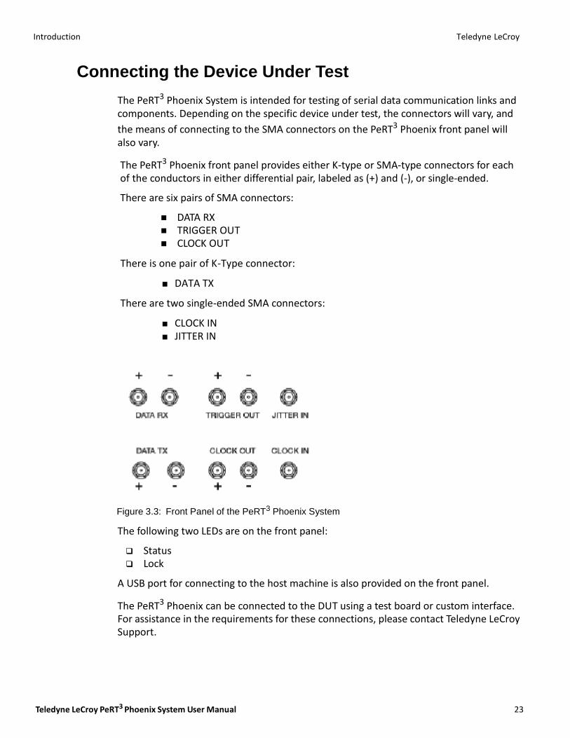
Connecting the Device Under Test
The PeRT3 Phoenix System is intended for testing of serial data communication links and components. Depending on the specific device under test, the connectors will vary, and
the means of connecting to the SMA connectors on the PeRT3 Phoenix front panel will also vary.
The PeRT3 Phoenix front panel provides either K-type or SMA-type connectors for each of the conductors in either differential pair, labeled as (+) and (‐), or single-ended.
There are six pairs of SMA connectors:
DATA RX TRIGGER OUT CLOCK OUT
There is one pair of K-Type connector:
DATA TX
There are two single-ended SMA connectors:
CLOCK IN JITTER IN
Figure 3.3: Front Panel of the PeRT3 Phoenix System
The following two LEDs are on the front panel:
Status Lock
A USB port for connecting to the host machine is also provided on the front panel.
The PeRT3 Phoenix can be connected to the DUT using a test board or custom interface. For assistance in the requirements for these connections, please contact Teledyne LeCroy Support.
24
Teledyne LeCroy Introduction
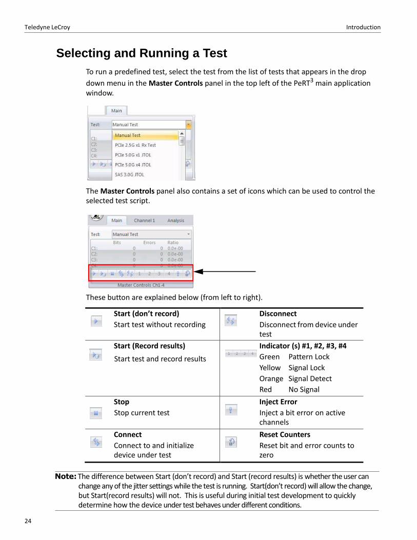
Selecting and Running a Test
To run a predefined test, select the test from the list of tests that appears in the drop
down menu in the Master Controls panel in the top left of the PeRT3 main application window.
The Master Controls panel also contains a set of icons which can be used to control the selected test script.
These button are explained below (from left to right).
Start (don’t record)
Start test without recording
Disconnect
Disconnect from device under test
Start (Record results)
Start test and record results
Indicator (s) #1, #2, #3, #4
Green Pattern Lock
Yellow Signal Lock
Orange Signal Detect
Red No Signal
Stop
Stop current test
Inject Error
Inject a bit error on active channels
Connect
Connect to and initialize device under test
Reset Counters
Reset bit and error counts to zero
Note: The difference between Start (don’t record) and Start (record results) is whether the user can
change any of the jitter settings while the test is running. Start(don’t record) will allow the change, but Start(record results) will not. This is useful during initial test development to quickly determine how the device under test behaves under different conditions.
Teledyne LeCroy PeRT3 Phoenix System User Manual 25
Introduction Teledyne LeCroy
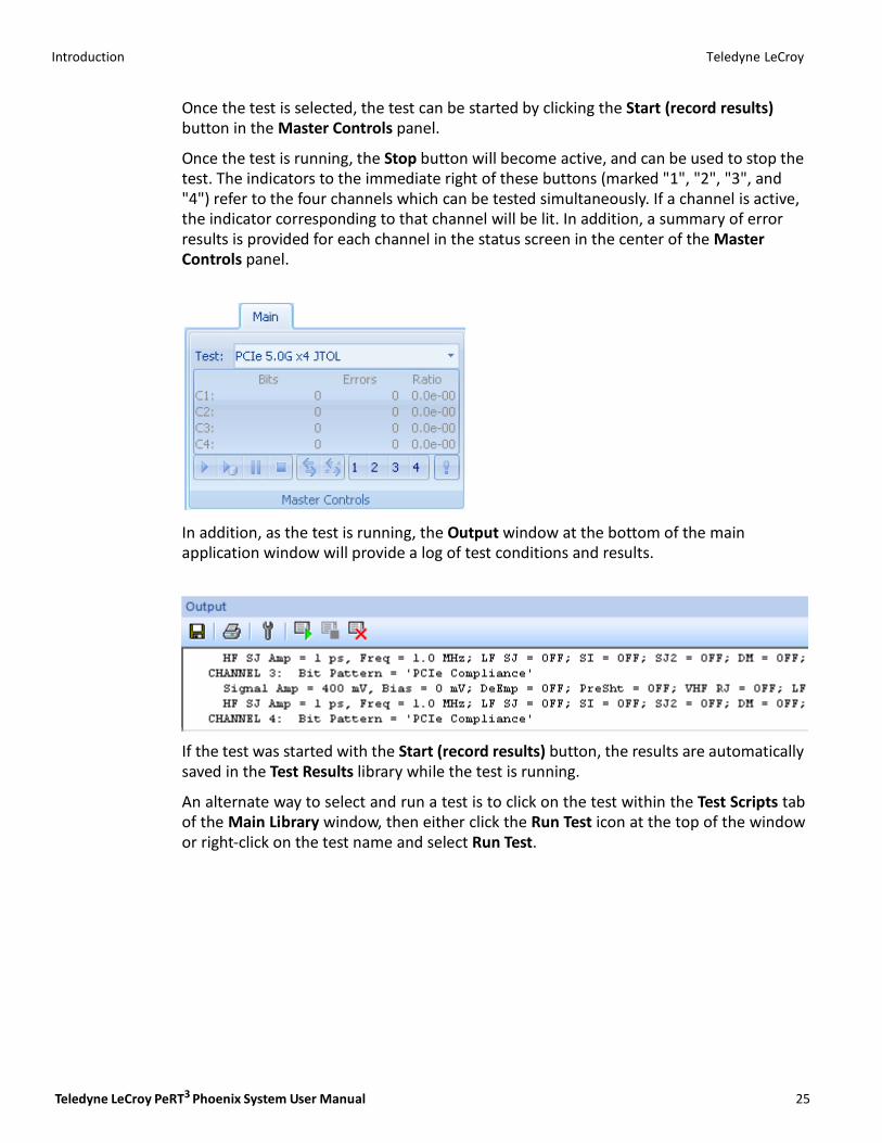
Once the test is selected, the test can be started by clicking the Start (record results) button in the Master Controls panel.
Once the test is running, the Stop button will become active, and can be used to stop the test. The indicators to the immediate right of these buttons (marked "1", "2", "3", and "4") refer to the four channels which can be tested simultaneously. If a channel is active, the indicator corresponding to that channel will be lit. In addition, a summary of error results is provided for each channel in the status screen in the center of the Master Controls panel.
In addition, as the test is running, the Output window at the bottom of the main application window will provide a log of test conditions and results.
If the test was started with the Start (record results) button, the results are automatically saved in the Test Results library while the test is running.
An alternate way to select and run a test is to click on the test within the Test Scripts tab of the Main Library window, then either click the Run Test icon at the top of the window or right‐click on the test name and select Run Test.
26
Teledyne LeCroy Introduction
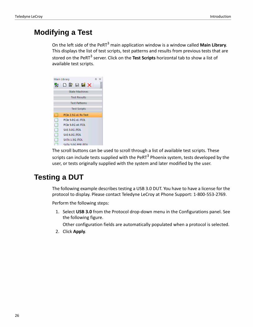
Modifying a Test
On the left side of the PeRT3 main application window is a window called Main Library. This displays the list of test scripts, test patterns and results from previous tests that are
stored on the PeRT3 server. Click on the Test Scripts horizontal tab to show a list of available test scripts.
The scroll buttons can be used to scroll through a list of available test scripts. These
scripts can include tests supplied with the PeRT3 Phoenix system, tests developed by the user, or tests originally supplied with the system and later modified by the user.
Testing a DUT
The following example describes testing a USB 3.0 DUT. You have to have a license for the protocol to display. Please contact Teledyne LeCroy at Phone Support: 1‐800‐553‐2769.
Perform the following steps:
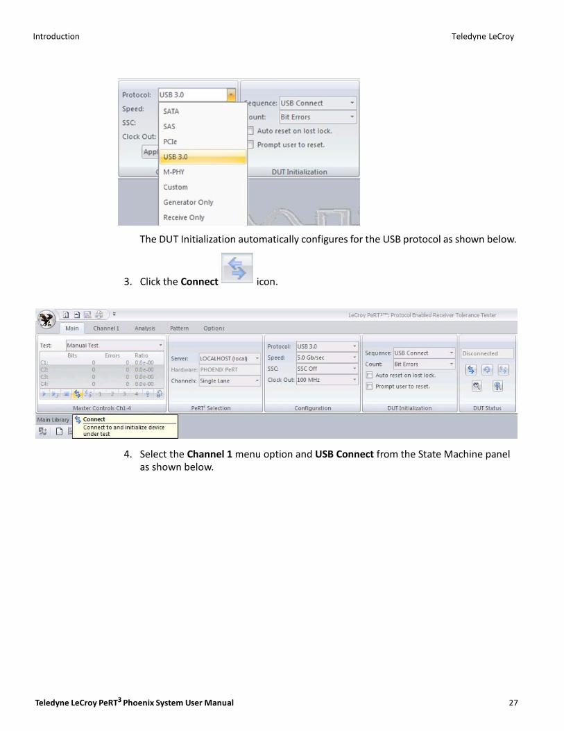
1. Select USB 3.0 from the Protocol drop‐down menu in the Configurations panel. See the following figure.
Other configuration fields are automatically populated when a protocol is selected.
2. Click Apply.
Teledyne LeCroy PeRT3 Phoenix System User Manual 27
Introduction Teledyne LeCroy
The DUT Initialization automatically configures for the USB protocol as shown below.
3. Click the Connect icon.
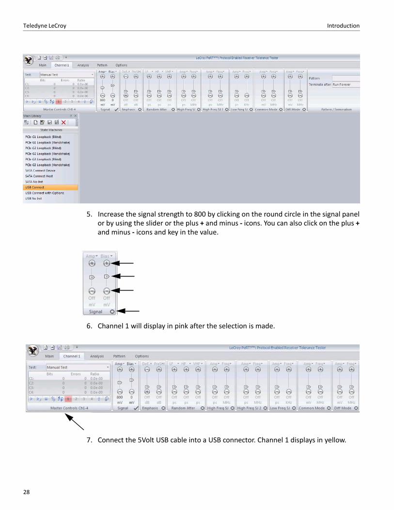
4. Select the Channel 1 menu option and USB Connect from the State Machine panel as shown below.
28
Teledyne LeCroy Introduction
5. Increase the signal strength to 800 by clicking on the round circle in the signal panel or by using the slider or the plus + and minus ‐ icons. You can also click on the plus + and minus ‐ icons and key in the value.
6. Channel 1 will display in pink after the selection is made.
7. Connect the 5Volt USB cable into a USB connector. Channel 1 displays in yellow.
Teledyne LeCroy PeRT3 Phoenix System User Manual 29
Introduction Teledyne LeCroy
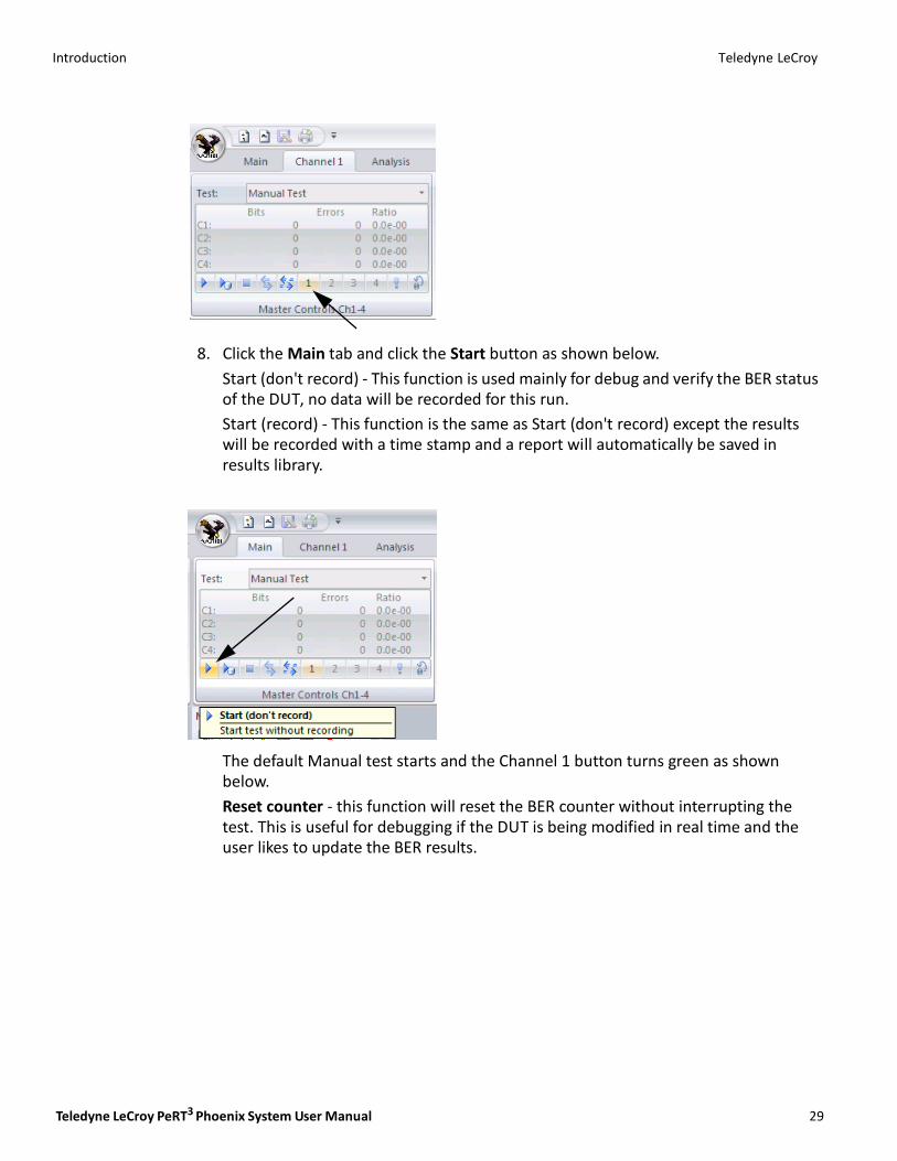
8. Click the Main tab and click the Start button as shown below.
Start (don't record) ‐ This function is used mainly for debug and verify the BER status of the DUT, no data will be recorded for this run.
Start (record) ‐ This function is the same as Start (don't record) except the results will be recorded with a time stamp and a report will automatically be saved in results library.
The default Manual test starts and the Channel 1 button turns green as shown below.
Reset counter ‐ this function will reset the BER counter without interrupting the test. This is useful for debugging if the DUT is being modified in real time and the user likes to update the BER results.

Teledyne LeCroy Introduction
30
Introduction Teledyne LeCroy
Teledyne LeCroy PeRT3 Phoenix System User Manual 31
Run Test Scripts
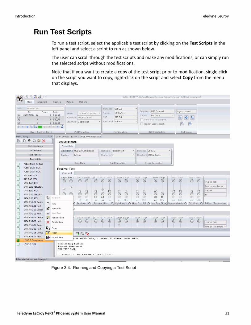
To run a test script, select the applicable test script by clicking on the Test Scripts in the left panel and select a script to run as shown below.
The user can scroll through the test scripts and make any modifications, or can simply run the selected script without modifications.
Note that if you want to create a copy of the test script prior to modification, single click on the script you want to copy, right‐click on the script and select Copy from the menu that displays.
Figure 3.4: Running and Copying a Test Script
Teledyne LeCroy Introduction
32
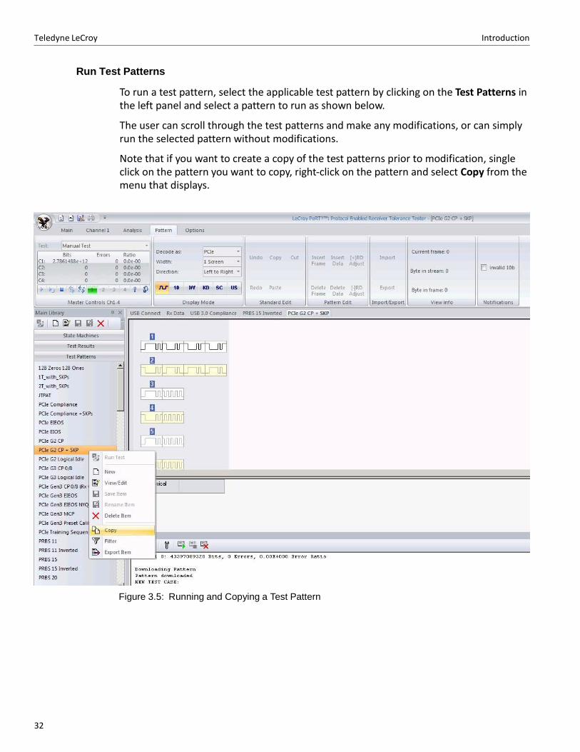
Run Test Patterns
To run a test pattern, select the applicable test pattern by clicking on the Test Patterns in the left panel and select a pattern to run as shown below.
The user can scroll through the test patterns and make any modifications, or can simply run the selected pattern without modifications.
Note that if you want to create a copy of the test patterns prior to modification, single click on the pattern you want to copy, right‐click on the pattern and select Copy from the menu that displays.
Figure 3.5: Running and Copying a Test Pattern
Teledyne LeCroy PeRT3 Phoenix System User Manual 33
Chapter 4
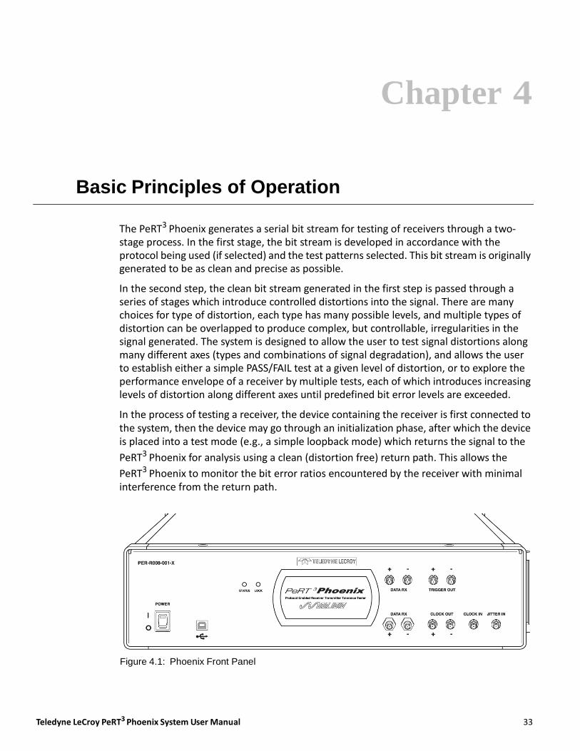
Basic Principles of Operation
The PeRT3 Phoenix generates a serial bit stream for testing of receivers through a two‐ stage process. In the first stage, the bit stream is developed in accordance with the protocol being used (if selected) and the test patterns selected. This bit stream is originally generated to be as clean and precise as possible.
In the second step, the clean bit stream generated in the first step is passed through a series of stages which introduce controlled distortions into the signal. There are many choices for type of distortion, each type has many possible levels, and multiple types of distortion can be overlapped to produce complex, but controllable, irregularities in the signal generated. The system is designed to allow the user to test signal distortions along many different axes (types and combinations of signal degradation), and allows the user to establish either a simple PASS/FAIL test at a given level of distortion, or to explore the performance envelope of a receiver by multiple tests, each of which introduces increasing levels of distortion along different axes until predefined bit error levels are exceeded.
In the process of testing a receiver, the device containing the receiver is first connected to the system, then the device may go through an initialization phase, after which the device is placed into a test mode (e.g., a simple loopback mode) which returns the signal to the
PeRT3 Phoenix for analysis using a clean (distortion free) return path. This allows the
PeRT3 Phoenix to monitor the bit error ratios encountered by the receiver with minimal interference from the return path.
Figure 4.1: Phoenix Front Panel
34
Teledyne LeCroy Introduction of Stress into Waveform
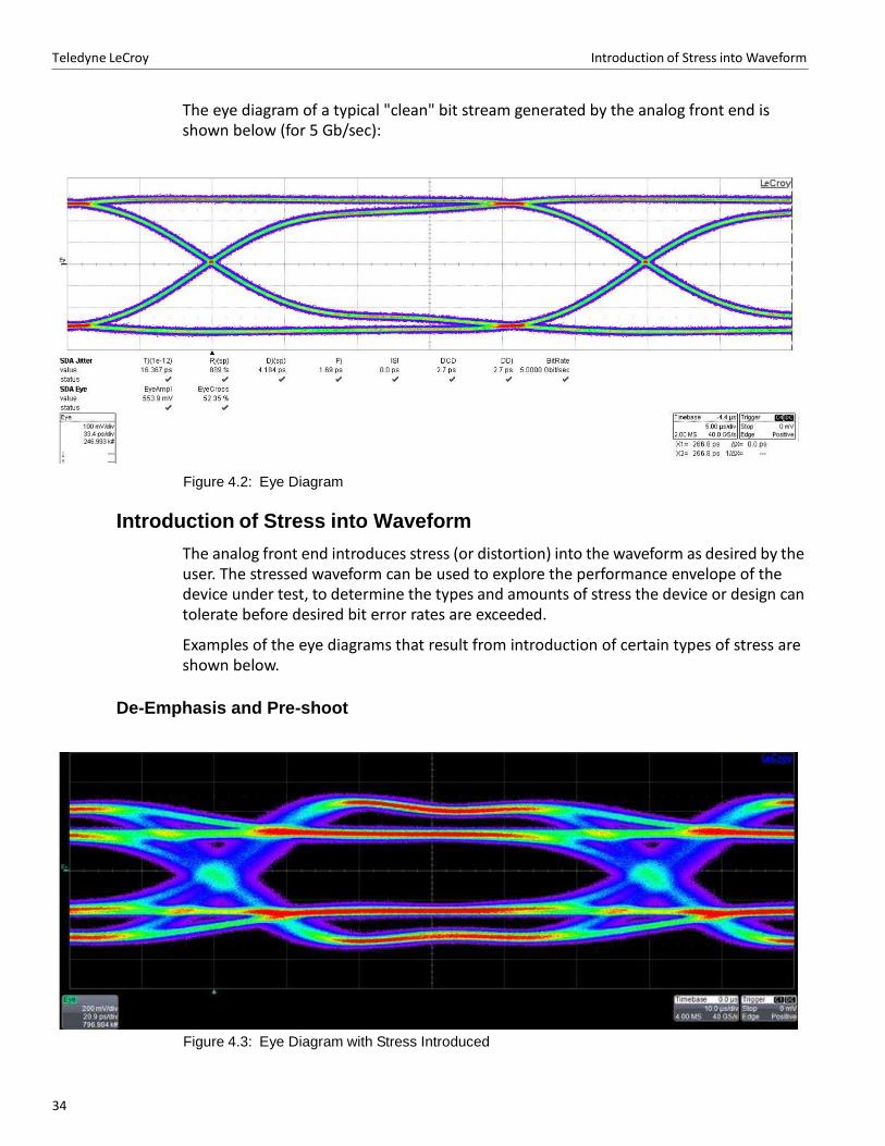
The eye diagram of a typical "clean" bit stream generated by the analog front end is shown below (for 5 Gb/sec):
Figure 4.2: Eye Diagram
Introduction of Stress into Waveform
The analog front end introduces stress (or distortion) into the waveform as desired by the user. The stressed waveform can be used to explore the performance envelope of the device under test, to determine the types and amounts of stress the device or design can tolerate before desired bit error rates are exceeded.
Examples of the eye diagrams that result from introduction of certain types of stress are shown below.
De-Emphasis and Pre-shoot
Figure 4.3: Eye Diagram with Stress Introduced
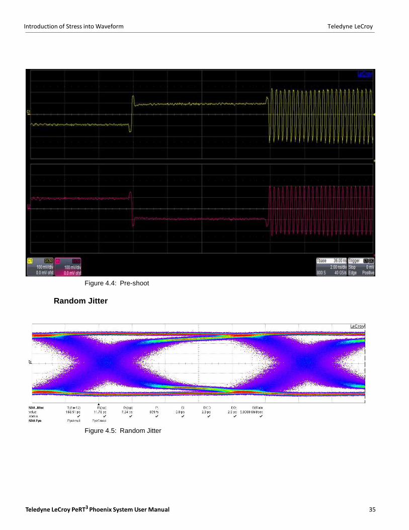
Teledyne LeCroy PeRT3 Phoenix System User Manual 35
Introduction of Stress into Waveform Teledyne LeCroy
Figure 4.4: Pre-shoot
Random Jitter
Figure 4.5: Random Jitter
36
Teledyne LeCroy Introduction of Stress into Waveform
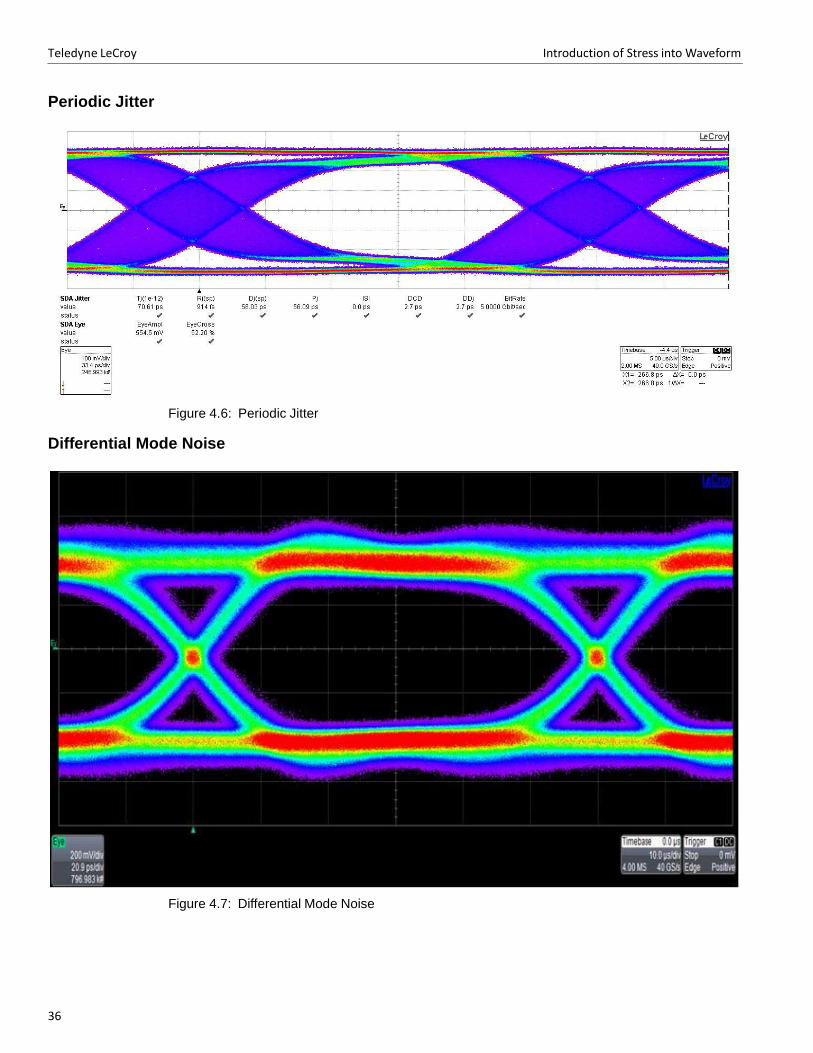
Periodic Jitter
Figure 4.6: Periodic Jitter
Differential Mode Noise
Figure 4.7: Differential Mode Noise
Teledyne LeCroy PeRT3 Phoenix System User Manual 37
Introduction of Stress into Waveform Teledyne LeCroy
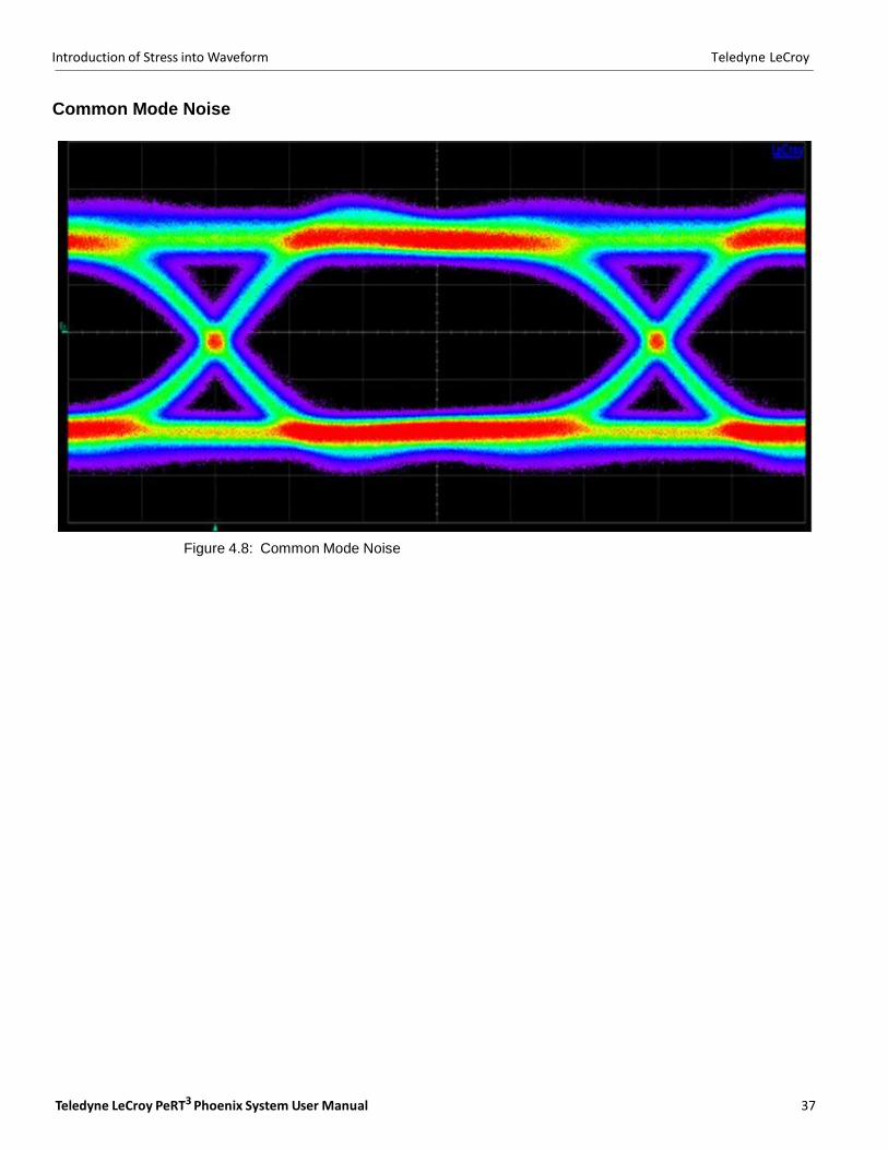
Common Mode Noise
Figure 4.8: Common Mode Noise

Teledyne LeCroy Introduction of Stress into Waveform
38

Teledyne LeCroy PeRT3 Phoenix System User Manual 39
Chapter 5
Software Overview
The PeRT3 application allows the user to control the PeRT3 Phoenix Test System, to develop test scripts for the system, to run saved test scripts, to run manual tests, and to review results of the current or previous tests. When reviewing the results of previous
tests, the host machine running the PeRT3 application does not need to be connected to
the PeRT3 Phoenix System hardware. This allows users to share test results with other engineers without requiring those users to have hardware connected.
Starting the PeRT3 Program
To start the PeRT3 program from the Start menu:
1. Click Start.
2. Select Programs.
3. Select LeCroy.
4. Select PeRT3.
5. Click LeCroy PeRT3.
The main application window for the PeRT3 displays a (see Figure 5.1 on page 40.)
40
Teledyne LeCroy Main Application Window
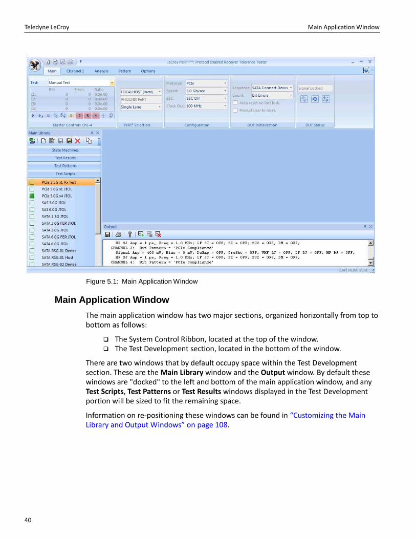
Figure 5.1: Main Application Window
Main Application Window
The main application window has two major sections, organized horizontally from top to bottom as follows:
The System Control Ribbon, located at the top of the window. The Test Development section, located in the bottom of the window.
There are two windows that by default occupy space within the Test Development section. These are the Main Library window and the Output window. By default these windows are "docked" to the left and bottom of the main application window, and any Test Scripts, Test Patterns or Test Results windows displayed in the Test Development portion will be sized to fit the remaining space.
Information on re‐positioning these windows can be found in “Customizing the Main Library and Output Windows” on page 108.

Teledyne LeCroy PeRT3 Phoenix System User Manual 41
Main Library Window Teledyne LeCroy
The positions and relative sizes for these sections as shown above are the default sizes and locations. The user has significant control over the locations and sizes of the various windows. Windows can be turned on and off to suit the user’s needs. See See “Control of Screen Appearance” on page 103.
Main Library Window
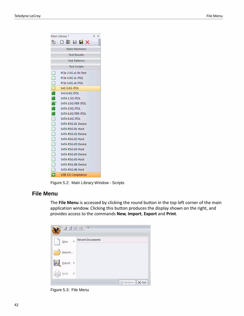
The Main Library window provides information on the status of a test script through the box located just left of the script name. An open box indicates that the script is stored on the server. A solid green square indicates that a copy of this script has been retrieved from the server and is currently on the client host machine as well. A solid green square with an asterisk indicates that the script has been modified but not yet saved on the server. A solid green square with an arrow indicates a test script which is currently running. The orange highlight indicates the test script(s) currently selected, or in other words the scripts to which Main Library commands located across the top of the window (View/Edit, Save, Rename, Delete, Filter or Export) will be applied (see Figure 5.2 on page 42).
42
Teledyne LeCroy File Menu
Figure 5.2: Main Library Window - Scripts
File Menu
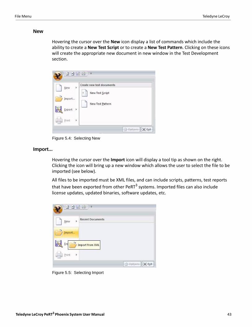
The File Menu is accessed by clicking the round button in the top left corner of the main application window. Clicking this button produces the display shown on the right, and provides access to the commands New, Import, Export and Print.
Figure 5.3: File Menu
Teledyne LeCroy PeRT3 Phoenix System User Manual 43
File Menu Teledyne LeCroy
New
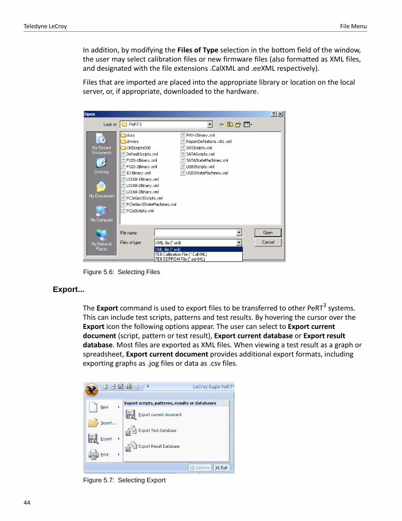
Hovering the cursor over the New icon display a list of commands which include the ability to create a New Test Script or to create a New Test Pattern. Clicking on these icons will create the appropriate new document in new window in the Test Development section.
Figure 5.4: Selecting New
Import...
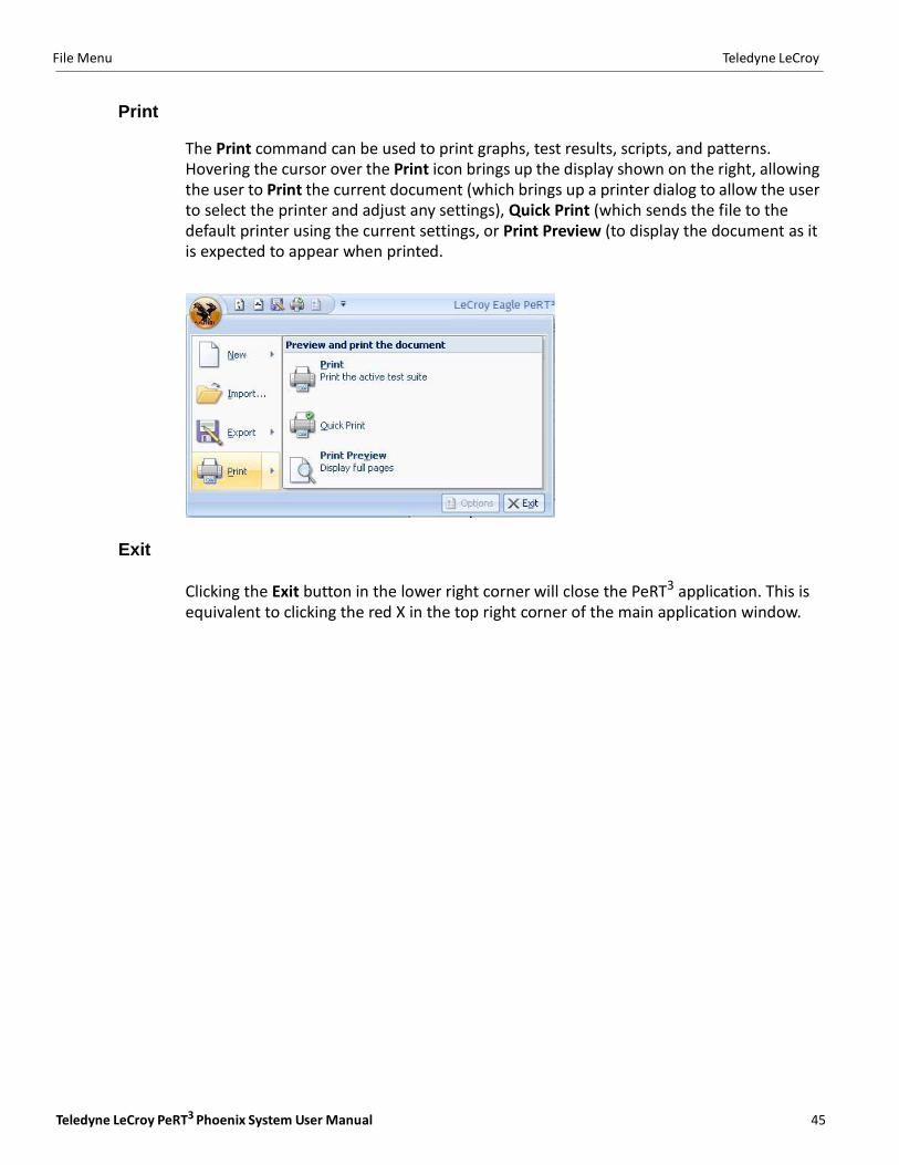
Hovering the cursor over the Import icon will display a tool tip as shown on the right. Clicking the icon will bring up a new window which allows the user to select the file to be imported (see below).
All files to be imported must be XML files, and can include scripts, patterns, test reports
that have been exported from other PeRT3 systems. Imported files can also include license updates, updated binaries, software updates, etc.
Figure 5.5: Selecting Import
44
Teledyne LeCroy File Menu
In addition, by modifying the Files of Type selection in the bottom field of the window, the user may select calibration files or new firmware files (also formatted as XML files, and designated with the file extensions .CalXML and .eeXML respectively).
Files that are imported are placed into the appropriate library or location on the local server, or, if appropriate, downloaded to the hardware.
Figure 5.6: Selecting Files
Export...
The Export command is used to export files to be transferred to other PeRT3 systems. This can include test scripts, patterns and test results. By hovering the cursor over the Export icon the following options appear. The user can select to Export current document (script, pattern or test result), Export current database or Export result database. Most files are exported as XML files. When viewing a test result as a graph or spreadsheet, Export current document provides additional export formats, including exporting graphs as .jog files or data as .csv files.
Figure 5.7: Selecting Export
Teledyne LeCroy PeRT3 Phoenix System User Manual 45
File Menu Teledyne LeCroy
The Print command can be used to print graphs, test results, scripts, and patterns. Hovering the cursor over the Print icon brings up the display shown on the right, allowing the user to Print the current document (which brings up a printer dialog to allow the user to select the printer and adjust any settings), Quick Print (which sends the file to the default printer using the current settings, or Print Preview (to display the document as it is expected to appear when printed.
Exit
Clicking the Exit button in the lower right corner will close the PeRT3 application. This is equivalent to clicking the red X in the top right corner of the main application window.

Teledyne LeCroy File Menu
46
Teledyne LeCroy PeRT3 Phoenix System User Manual 47
Chapter 6
Manual Testing
The PeRT3 Phoenix supports the ability to conduct quick manual tests in addition to running pre‐programmed test scripts supplied with the system or developed by the user.
Manual testing is controlled by the System Control Ribbon located at the top of the PeRT3
main application window. Manual testing is a good introduction to how to develop test scripts, since the steps followed are largely the same.
To set up a test, work from left to right across the panels in the Main tab, starting with the
PeRT3 panel to select the system to be used, then the Configuration panel to select the protocol and data rate, followed by the DUT Initialization panel to specify the DUT setup and initialization sequences, and finally to the DUT Status panel to connect to the DUT.
System Control Ribbon - Main Tab
If the Main tab along the top of the System Control Ribbon is clicked, the ribbon will show a series of five panels, as follows:
Master Controls
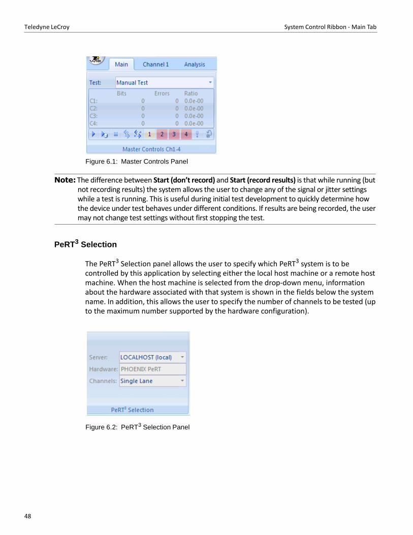
The Master Controls panel allows the user to specify the test to be run. If a manual test is desired, select Manual Test in the drop‐down menu (this is the first item on the list). This allows the user to Start (don’t record), Start (record results), Stop the test, to Connect or Disconnect from the DUT, and indicates which channels are being tested through the "1", "2", "3" and "4" which function as on‐screen LEDs to show which channels are active. Also, the panel shows the status of bit errors encountered on each of the channels while the test is running and allows the user to deliberately inject a bit error (into all active channels) by clicking the button on the lower right. The user can also reset the counters (see Figure 6.1 on page 48).
48
Teledyne LeCroy System Control Ribbon ‐ Main Tab
Figure 6.1: Master Controls Panel
Note: The difference between Start (don’t record) and Start (record results) is that while running (but
not recording results) the system allows the user to change any of the signal or jitter settings while a test is running. This is useful during initial test development to quickly determine how the device under test behaves under different conditions. If results are being recorded, the user may not change test settings without first stopping the test.
PeRT3 Selection
The PeRT3 Selection panel allows the user to specify which PeRT3 system is to be controlled by this application by selecting either the local host machine or a remote host machine. When the host machine is selected from the drop‐down menu, information about the hardware associated with that system is shown in the fields below the system name. In addition, this allows the user to specify the number of channels to be tested (up to the maximum number supported by the hardware configuration).
Figure 6.2: PeRT3 Selection Panel
Teledyne LeCroy PeRT3 Phoenix System User Manual 49
System Control Ribbon ‐ Main Tab Teledyne LeCroy
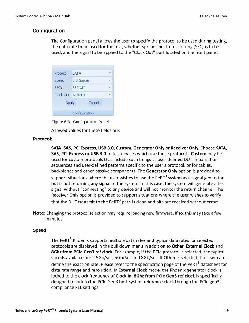
Configuration
The Configuration panel allows the user to specify the protocol to be used during testing, the data rate to be used for the test, whether spread spectrum clocking (SSC) is to be used, and the signal to be applied to the "Clock Out" port located on the front panel.
Figure 6.3: Configuration Panel
Allowed values for these fields are:
Protocol:
SATA, SAS, PCI Express, USB 3.0, Custom, Generator Only or Receiver Only. Choose SATA, SAS, PCI Express or USB 3.0 to test devices which use those protocols. Custom may be used for custom protocols that include such things as user‐defined DUT initialization sequences and user‐defined patterns specific to the user’s protocol, or for cables, backplanes and other passive components. The Generator Only option is provided to
support situations where the user wishes to use the PeRT3 system as a signal generator but is not returning any signal to the system. In this case, the system will generate a test signal without "connecting" to any device and will not monitor the return channel. The Receiver Only option is provided to support situations where the user wishes to verify
that the DUT transmit to the PeRT3 path is clean and bits are received without errors.
Note: Changing the protocol selection may require loading new firmware. If so, this may take a few minutes.
Speed:
The PeRT3 Phoenix supports multiple data rates and typical data rates for selected protocols are displayed in the pull down menu in addition to Other, External Clock and 8Ghz from PCIe Gen3 ref clock. For example, if the PCIe protocol is selected, the typical speeds available are 2.5Gb/sec, 5Gb/Sec and 8Gb/sec. If Other is selected, the user can
define the exact bit rate. Please refer to the specification page of the PeRT3 datasheet for data rate range and resolution. In External Clock mode, the Phoenix generator clock is locked to the clock frequency of Clock In. 8Ghz from PCIe Gen3 ref clock is specifically designed to lock to the PCIe Gen3 host system reference clock through the PCIe gen3 compliance PLL settings.
50
Teledyne LeCroy System Control Ribbon ‐ Main Tab
SSC:
Controls whether spread spectrum clocking (SSC) is used for clocking the outgoing serial stream.
Clock Out:
This controls the Clock Out connection on the front panel of the PeRT3 Phoenix. The user can select At Rate, 100 MHz, 125 MHz, 10 MHz or Other. At Rate will use the data rate of the system. Other allows the user to specify an arbitrary clock out rate. If a rate is selected which is not an integral division of the base rate, the rate will be adjusted to the nearest rate than can be achieved using the clock divider hardware. The Clock Out signal can be controlled further (to introduce delay or jitter) through the Clock Out under the Options tab.
Changing any of these parameters does not change the system configuration until the Apply button is clicked. The two buttons (Apply and Cancel) allow the user to set a complete configuration before applying it to the system.
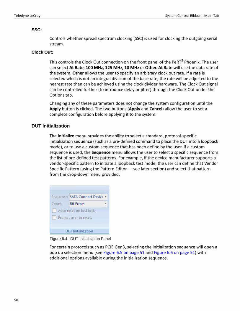
DUT Initialization
The Initialize menu provides the ability to select a standard, protocol‐specific initialization sequence (such as a pre‐defined command to place the DUT into a loopback mode), or to use a custom sequence that has been define by the user. If a custom sequence is used, the Sequence menu allows the user to select a specific sequence from the list of pre‐defined test patterns. For example, if the device manufacturer supports a vendor‐specific pattern to initiate a loopback test mode, the user can define that Vendor Specific Pattern (using the Pattern Editor — see later section) and select that pattern from the drop‐down menu provided.
Figure 6.4: DUT Initialization Panel
For certain protocols such as PCIE Gen3, selecting the initialization sequence will open a pop up selection menu (see Figure 6.5 on page 51 and Figure 6.6 on page 51) with additional options available during the initialization sequence.
Teledyne LeCroy PeRT3 Phoenix System User Manual 51
System Control Ribbon ‐ Main Tab Teledyne LeCroy
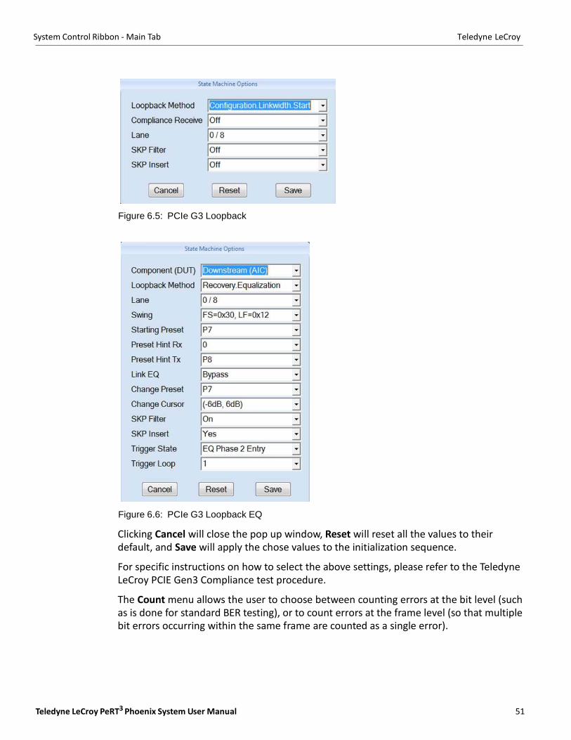
Figure 6.5: PCIe G3 Loopback
Figure 6.6: PCIe G3 Loopback EQ
Clicking Cancel will close the pop up window, Reset will reset all the values to their default, and Save will apply the chose values to the initialization sequence.
For specific instructions on how to select the above settings, please refer to the Teledyne LeCroy PCIE Gen3 Compliance test procedure.
The Count menu allows the user to choose between counting errors at the bit level (such as is done for standard BER testing), or to count errors at the frame level (so that multiple bit errors occurring within the same frame are counted as a single error).
52
Teledyne LeCroy System Control Ribbon ‐‐ Channel Tabs
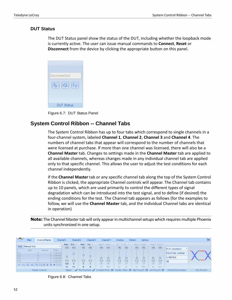
DUT Status
The DUT Status panel show the status of the DUT, including whether the loopback mode is currently active. The user can issue manual commands to Connect, Reset or Disconnect from the device by clicking the appropriate button on this panel.
Figure 6.7: DUT Status Panel
System Control Ribbon -- Channel Tabs
The System Control Ribbon has up to four tabs which correspond to single channels in a four‐channel system, labeled Channel 1, Channel 2, Channel 3 and Channel 4. The numbers of channel tabs that appear will correspond to the number of channels that were licensed at purchase. If more than one channel was licensed, there will also be a Channel Master tab. Changes to settings made in the Channel Master tab are applied to all available channels, whereas changes made in any individual channel tab are applied only to that specific channel. This allows the user to adjust the test conditions for each channel independently.
If the Channel Master tab or any specific channel tab along the top of the System Control Ribbon is clicked, the appropriate Channel controls will appear. The Channel tab contains up to 10 panels, which are used primarily to control the different types of signal degradation which can be introduced into the test signal, and to define (if desired) the ending conditions for the test. The Channel tab appears as follows (for the examples to follow, we will use the Channel Master tab, and the individual Channel tabs are identical in operation)
Note: The Channel Master tab will only appear in multichannel setups which requires multiple Phoenix
units synchronized in one setup.
Figure 6.8: Channel Tabs
Teledyne LeCroy PeRT3 Phoenix System User Manual 53
System Control Ribbon ‐‐ Channel Tabs Teledyne LeCroy
Once the device has been configured, the user is likely to use the Channel tab(s) in the Manual Test mode to control and modify the test conditions while developing an appropriate test for the device. These tabs allow immediate access to all forms of signal stress that can be introduced and allows the user to quickly experiment with different forms and levels of stress to roughly determine the performance envelope for the device.
Panels that can be accessed from the Channel tabs include the following:
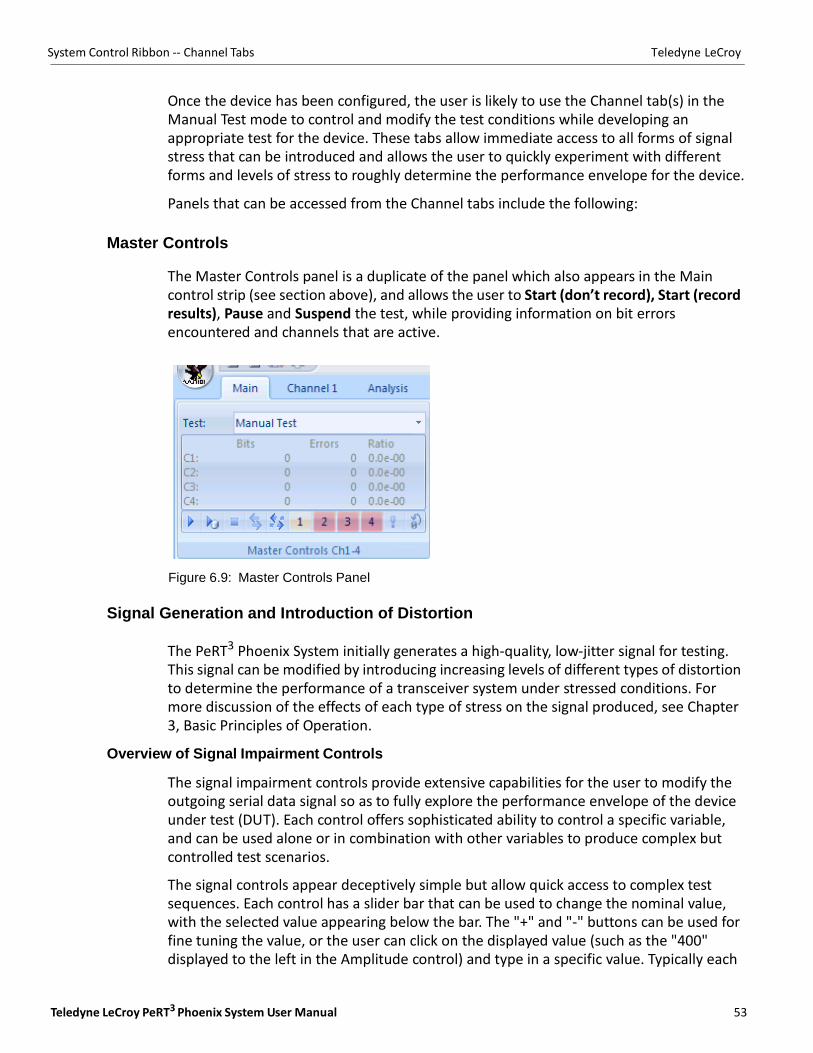
Master Controls
The Master Controls panel is a duplicate of the panel which also appears in the Main control strip (see section above), and allows the user to Start (don’t record), Start (record results), Pause and Suspend the test, while providing information on bit errors encountered and channels that are active.
Figure 6.9: Master Controls Panel
Signal Generation and Introduction of Distortion
The PeRT3 Phoenix System initially generates a high‐quality, low‐jitter signal for testing. This signal can be modified by introducing increasing levels of different types of distortion to determine the performance of a transceiver system under stressed conditions. For more discussion of the effects of each type of stress on the signal produced, see Chapter 3, Basic Principles of Operation.
Overview of Signal Impairment Controls
The signal impairment controls provide extensive capabilities for the user to modify the outgoing serial data signal so as to fully explore the performance envelope of the device under test (DUT). Each control offers sophisticated ability to control a specific variable, and can be used alone or in combination with other variables to produce complex but controlled test scenarios.
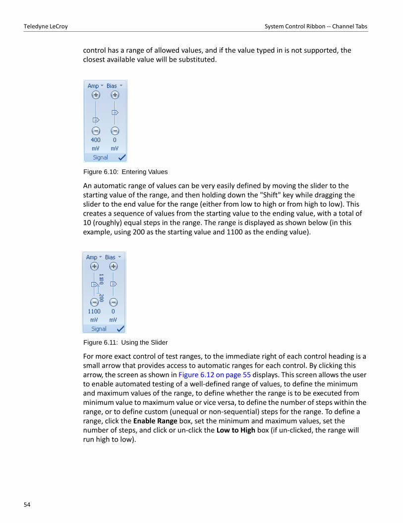
The signal controls appear deceptively simple but allow quick access to complex test sequences. Each control has a slider bar that can be used to change the nominal value, with the selected value appearing below the bar. The "+" and "‐" buttons can be used for fine tuning the value, or the user can click on the displayed value (such as the "400" displayed to the left in the Amplitude control) and type in a specific value. Typically each
54
Teledyne LeCroy System Control Ribbon ‐‐ Channel Tabs
control has a range of allowed values, and if the value typed in is not supported, the closest available value will be substituted.
Figure 6.10: Entering Values
An automatic range of values can be very easily defined by moving the slider to the starting value of the range, and then holding down the "Shift" key while dragging the slider to the end value for the range (either from low to high or from high to low). This creates a sequence of values from the starting value to the ending value, with a total of 10 (roughly) equal steps in the range. The range is displayed as shown below (in this example, using 200 as the starting value and 1100 as the ending value).
Figure 6.11: Using the Slider
For more exact control of test ranges, to the immediate right of each control heading is a small arrow that provides access to automatic ranges for each control. By clicking this arrow, the screen as shown in Figure 6.12 on page 55 displays. This screen allows the user to enable automated testing of a well‐defined range of values, to define the minimum and maximum values of the range, to define whether the range is to be executed from minimum value to maximum value or vice versa, to define the number of steps within the range, or to define custom (unequal or non‐sequential) steps for the range. To define a range, click the Enable Range box, set the minimum and maximum values, set the number of steps, and click or un‐click the Low to High box (if un‐clicked, the range will run high to low).
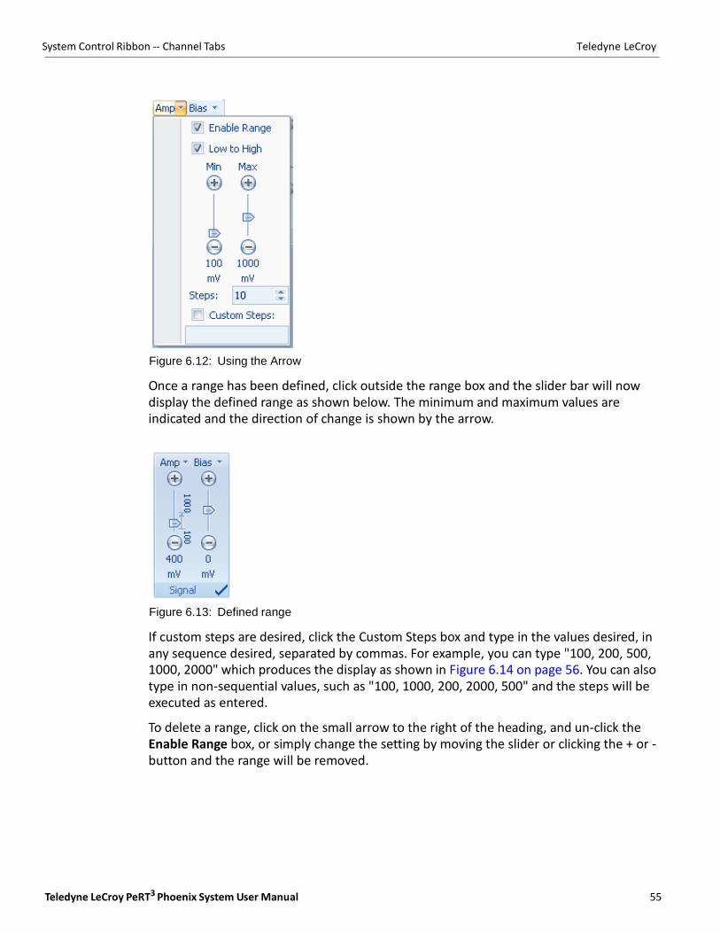
Teledyne LeCroy PeRT3 Phoenix System User Manual 55
System Control Ribbon ‐‐ Channel Tabs Teledyne LeCroy
Figure 6.12: Using the Arrow
Once a range has been defined, click outside the range box and the slider bar will now display the defined range as shown below. The minimum and maximum values are indicated and the direction of change is shown by the arrow.
Figure 6.13: Defined range
If custom steps are desired, click the Custom Steps box and type in the values desired, in any sequence desired, separated by commas. For example, you can type "100, 200, 500, 1000, 2000" which produces the display as shown in Figure 6.14 on page 56. You can also type in non‐sequential values, such as "100, 1000, 200, 2000, 500" and the steps will be executed as entered.
To delete a range, click on the small arrow to the right of the heading, and un‐click the Enable Range box, or simply change the setting by moving the slider or clicking the + or ‐ button and the range will be removed.

56
Teledyne LeCroy System Control Ribbon ‐‐ Channel Tabs
Figure 6.14: Custom Values
An aid to entering and changing values for signal impairment controls can be found by turning on the On‐screen Keypad. The On‐screen Keypad can be turned on from the View panel of the Options tab. When turned on, if the numeric value below the slider bar in any control is clicked, the value will be highlighted and the On‐screen Keypad will appear as shown below.
Figure 6.15: On-screen Keypad

Teledyne LeCroy PeRT3 Phoenix System User Manual 57
System Control Ribbon ‐‐ Channel Tabs Teledyne LeCroy
Signal
The Signal panel allows the user to control the amplitude and bias of the differential signal. By default, the Signal panel is inactive (turned off) when the system is first turned on, as shown by the circle in the lower right corner of the panel. Before any testing can take place, the user must turn this on (click to change to a check mark) and specify the desired signal characteristics.
Signal amplitude (Amp) can be controlled over the range from 100 mV to 2200 mV in increments of 5 mV. Signal amplitude is the nominal voltage of the differential signal, and is a measure of the overall signal power. Low signal amplitude can be used to test for the limits of receiver sensitivity (additional losses due to connectors and cables should be taken into account). High signal amplitudes can be used to test for receiver saturation or even damage limits to electronics.
Signal bias can be controlled over the range ‐1800 mV to +1800 mV in increments of 5 mV. Signal bias is the offset (from ground) that is applied to the differential signal, or in other words, the DC component of the signal.
Figure 6.16: Signal Panel
Note: All signal impairment controls are turned off by default. All controls must first be turned on by
clicking the circle in the bottom right corner of each panel. When the control is active, the circle will change to a check mark
De-Emphasis
The Emphasis panel allow the user to control the 3 tap emphasis setting on the transmit signal. The transmit emphasis consisting of De‐emphasis and PreShoot. By Default, emphasis is turned off (see Figure 6.17 on page 58).
De‐emphasis (DeE) values can be controlled over the range from ‐12dB to 0dB with 0.1dB resolution (nominal values) and PreShoot (PreSht) can be controlled over the range 0dB to 9dB with 0.1dB resolution (nominal values). De‐emphasis and PreShoot can be added independently for effects of a full bit 2‐tap equalizer or be added simultaneously as a full bit 3‐tap equalizer. Both values are calibrated based on the PCIE Gen3 Transmitter equalization calibration methodology and should be calibrated before each test based on the channel applied to the test system.
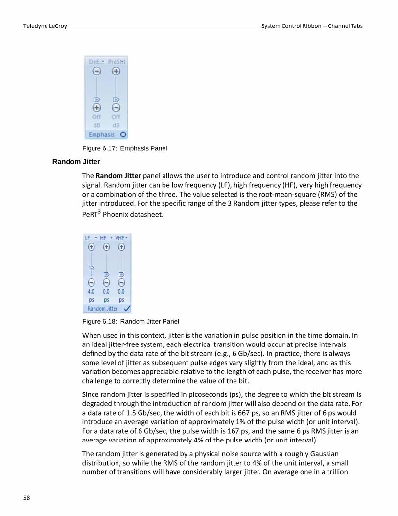
58
Teledyne LeCroy System Control Ribbon ‐‐ Channel Tabs
Figure 6.17: Emphasis Panel
Random Jitter
The Random Jitter panel allows the user to introduce and control random jitter into the signal. Random jitter can be low frequency (LF), high frequency (HF), very high frequency or a combination of the three. The value selected is the root‐mean‐square (RMS) of the jitter introduced. For the specific range of the 3 Random jitter types, please refer to the
PeRT3 Phoenix datasheet.
Figure 6.18: Random Jitter Panel
When used in this context, jitter is the variation in pulse position in the time domain. In an ideal jitter‐free system, each electrical transition would occur at precise intervals defined by the data rate of the bit stream (e.g., 6 Gb/sec). In practice, there is always some level of jitter as subsequent pulse edges vary slightly from the ideal, and as this variation becomes appreciable relative to the length of each pulse, the receiver has more challenge to correctly determine the value of the bit.
Since random jitter is specified in picoseconds (ps), the degree to which the bit stream is degraded through the introduction of random jitter will also depend on the data rate. For a data rate of 1.5 Gb/sec, the width of each bit is 667 ps, so an RMS jitter of 6 ps would introduce an average variation of approximately 1% of the pulse width (or unit interval). For a data rate of 6 Gb/sec, the pulse width is 167 ps, and the same 6 ps RMS jitter is an average variation of approximately 4% of the pulse width (or unit interval).
The random jitter is generated by a physical noise source with a roughly Gaussian distribution, so while the RMS of the random jitter to 4% of the unit interval, a small number of transitions will have considerably larger jitter. On average one in a trillion
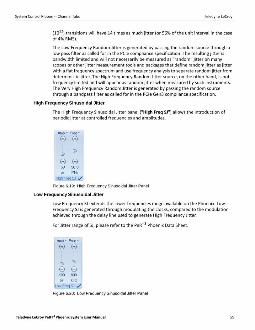
Teledyne LeCroy PeRT3 Phoenix System User Manual 59
System Control Ribbon ‐‐ Channel Tabs Teledyne LeCroy
(1012) transitions will have 14 times as much jitter (or 56% of the unit interval in the case of 4% RMS).
The Low Frequency Random Jitter is generated by passing the random source through a low pass filter as called for in the PCIe compliance specification. The resulting jitter is bandwidth limited and will not necessarily be measured as "random" jitter on many scopes or other jitter measurement tools and packages that define random jitter as jitter with a flat frequency spectrum and use frequency analysis to separate random jitter from deterministic jitter. The High Frequency Random Jitter source, on the other hand, is not frequency limited and will appear as random jitter when measured by such instruments. The Very High Frequency Random Jitter is generated by passing the random source through a bandpass filter as called for in the PCIe Gen3 compliance specification.
High Frequency Sinusoidal Jitter
The High Frequency Sinusoidal Jitter panel ("High Freq SJ") allows the introduction of periodic jitter at controlled frequencies and amplitudes.
Figure 6.19: High Frequency Sinusoidal Jitter Panel
Low Frequency Sinusoidal Jitter
Low Frequency SJ extends the lower frequencies range available on the Phoenix. Low Frequency SJ is generated through modulating the clocks, compared to the modulation achieved through the delay line used to generate High Frequency Jitter.
For Jitter range of SJ, please refer to the PeRT3 Phoenix Data Sheet.
Figure 6.20: Low Frequency Sinusoidal Jitter Panel
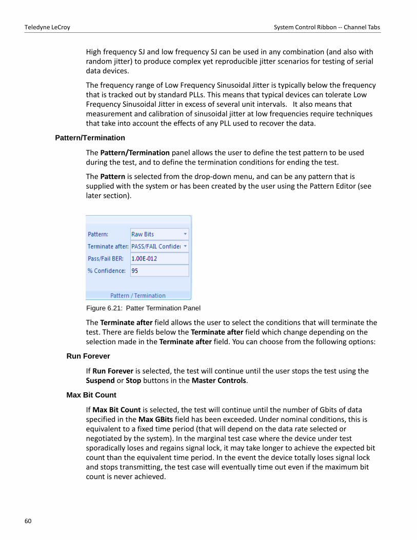
60
Teledyne LeCroy System Control Ribbon ‐‐ Channel Tabs
High frequency SJ and low frequency SJ can be used in any combination (and also with random jitter) to produce complex yet reproducible jitter scenarios for testing of serial data devices.
The frequency range of Low Frequency Sinusoidal Jitter is typically below the frequency that is tracked out by standard PLLs. This means that typical devices can tolerate Low Frequency Sinusoidal Jitter in excess of several unit intervals. It also means that measurement and calibration of sinusoidal jitter at low frequencies require techniques that take into account the effects of any PLL used to recover the data.
Pattern/Termination
The Pattern/Termination panel allows the user to define the test pattern to be used during the test, and to define the termination conditions for ending the test.
The Pattern is selected from the drop‐down menu, and can be any pattern that is supplied with the system or has been created by the user using the Pattern Editor (see later section).
Figure 6.21: Patter Termination Panel
The Terminate after field allows the user to select the conditions that will terminate the test. There are fields below the Terminate after field which change depending on the selection made in the Terminate after field. You can choose from the following options:
Run Forever
If Run Forever is selected, the test will continue until the user stops the test using the Suspend or Stop buttons in the Master Controls.
Max Bit Count
If Max Bit Count is selected, the test will continue until the number of Gbits of data specified in the Max GBits field has been exceeded. Under nominal conditions, this is equivalent to a fixed time period (that will depend on the data rate selected or negotiated by the system). In the marginal test case where the device under test sporadically loses and regains signal lock, it may take longer to achieve the expected bit count than the equivalent time period. In the event the device totally loses signal lock and stops transmitting, the test case will eventually time out even if the maximum bit count is never achieved.
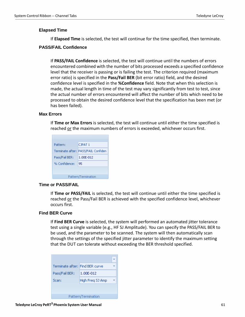
Teledyne LeCroy PeRT3 Phoenix System User Manual 61
System Control Ribbon ‐‐ Channel Tabs Teledyne LeCroy
Elapsed Time
If Elapsed Time is selected, the test will continue for the time specified, then terminate.
PASS/FAIL Confidence
If PASS/FAIL Confidence is selected, the test will continue until the numbers of errors encountered combined with the number of bits processed exceeds a specified confidence level that the receiver is passing or is failing the test. The criterion required (maximum error ratio) is specified in the Pass/Fail BER (bit error ratio) field, and the desired confidence level is specified in the %Confidence field. Note that when this selection is made, the actual length in time of the test may vary significantly from test to test, since the actual number of errors encountered will affect the number of bits which need to be processed to obtain the desired confidence level that the specification has been met (or has been failed).
Max Errors
If Time or Max Errors is selected, the test will continue until either the time specified is reached or the maximum numbers of errors is exceeded, whichever occurs first.
Time or PASS/FAIL
If Time or PASS/FAIL is selected, the test will continue until either the time specified is reached or the Pass/Fail BER is achieved with the specified confidence level, whichever occurs first.
Find BER Curve
If Find BER Curve is selected, the system will performed an automated jitter tolerance test using a single variable (e.g., HF SJ Amplitude). You can specify the PASS/FAIL BER to be used, and the parameter to be scanned. The system will then automatically scan through the settings of the specified jitter parameter to identify the maximum setting that the DUT can tolerate without exceeding the BER threshold specified.
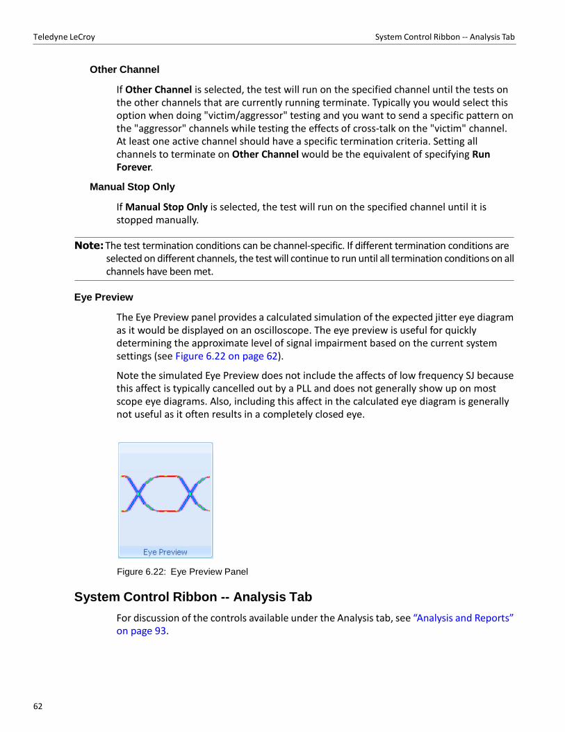
62
Teledyne LeCroy System Control Ribbon ‐‐ Analysis Tab
Other Channel
If Other Channel is selected, the test will run on the specified channel until the tests on the other channels that are currently running terminate. Typically you would select this option when doing "victim/aggressor" testing and you want to send a specific pattern on the "aggressor" channels while testing the effects of cross‐talk on the "victim" channel. At least one active channel should have a specific termination criteria. Setting all channels to terminate on Other Channel would be the equivalent of specifying Run Forever.
Manual Stop Only
If Manual Stop Only is selected, the test will run on the specified channel until it is stopped manually.
Note: The test termination conditions can be channel‐specific. If different termination conditions are
selected on different channels, the test will continue to run until all termination conditions on all channels have been met.
Eye Preview
The Eye Preview panel provides a calculated simulation of the expected jitter eye diagram as it would be displayed on an oscilloscope. The eye preview is useful for quickly determining the approximate level of signal impairment based on the current system settings (see Figure 6.22 on page 62).
Note the simulated Eye Preview does not include the affects of low frequency SJ because this affect is typically cancelled out by a PLL and does not generally show up on most scope eye diagrams. Also, including this affect in the calculated eye diagram is generally not useful as it often results in a completely closed eye.
Figure 6.22: Eye Preview Panel
System Control Ribbon -- Analysis Tab
For discussion of the controls available under the Analysis tab, see “Analysis and Reports” on page 93.
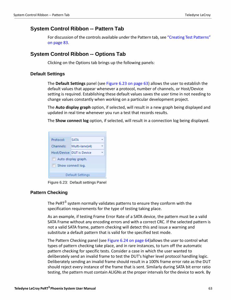
Teledyne LeCroy PeRT3 Phoenix System User Manual 63
System Control Ribbon ‐‐ Pattern Tab Teledyne LeCroy
System Control Ribbon -- Pattern Tab
For discussion of the controls available under the Pattern tab, see “Creating Test Patterns” on page 83.
System Control Ribbon -- Options Tab
Clicking on the Options tab brings up the following panels:
Default Settings
The Default Settings panel (see Figure 6.23 on page 63) allows the user to establish the default values that appear whenever a protocol, number of channels, or Host/Device setting is required. Establishing these default values saves the user time in not needing to change values constantly when working on a particular development project.
The Auto display graph option, if selected, will result in a new graph being displayed and updated in real time whenever you run a test that records results.
The Show connect log option, if selected, will result in a connection log being displayed.
Figure 6.23: Default settings Panel
Pattern Checking
The PeRT3 system normally validates patterns to ensure they conform with the specification requirements for the type of testing taking place.
As an example, if testing Frame Error Rate of a SATA device, the pattern must be a valid SATA Frame without any encoding errors and with a correct CRC. If the selected pattern is not a valid SATA frame, pattern checking will detect this and issue a warning and substitute a default pattern that is valid for the specified test mode.
The Pattern Checking panel (see Figure 6.24 on page 64)allows the user to control what types of pattern checking take place, and in rare instances, to turn off the automatic pattern checking for specific tests. Consider a case in which the user wanted to deliberately send an invalid frame to test the DUT's higher level protocol handling logic. Deliberately sending an invalid frame should result in a 100% frame error rate as the DUT should reject every instance of the frame that is sent. Similarly during SATA bit error ratio testing, the pattern must contain ALIGNs at the proper intervals for the device to work. By
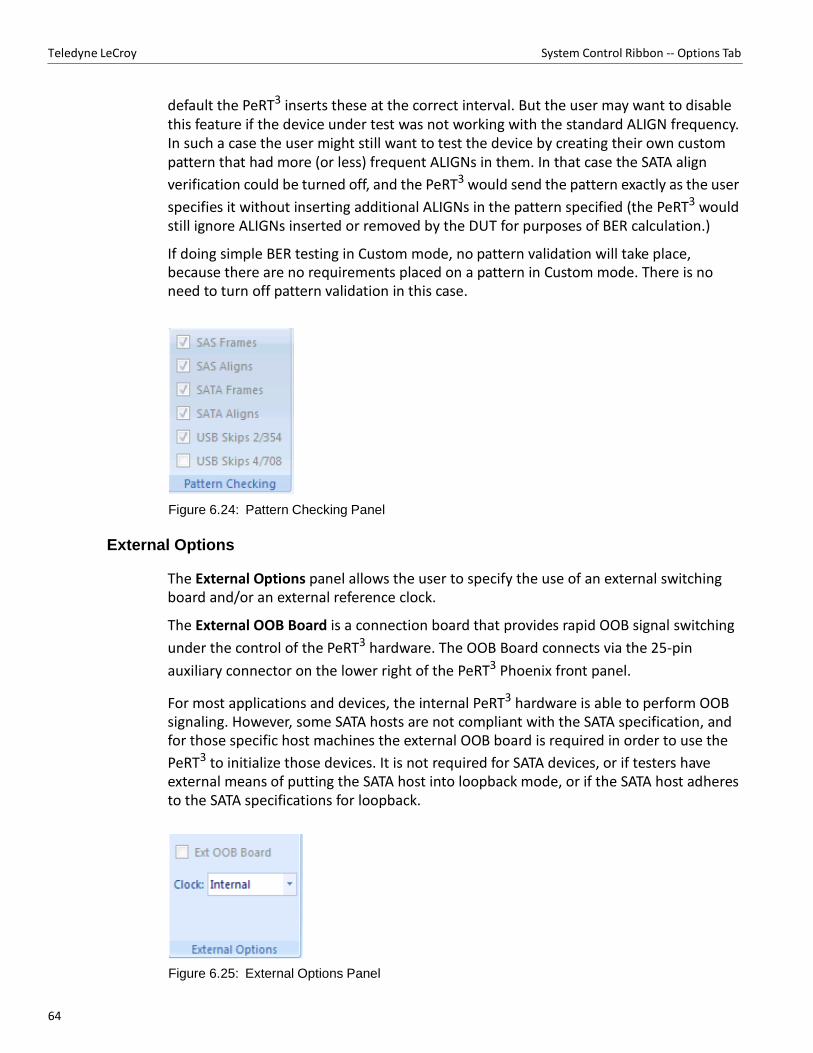
64
Teledyne LeCroy System Control Ribbon ‐‐ Options Tab
default the PeRT3 inserts these at the correct interval. But the user may want to disable this feature if the device under test was not working with the standard ALIGN frequency. In such a case the user might still want to test the device by creating their own custom pattern that had more (or less) frequent ALIGNs in them. In that case the SATA align
verification could be turned off, and the PeRT3 would send the pattern exactly as the user
specifies it without inserting additional ALIGNs in the pattern specified (the PeRT3 would still ignore ALIGNs inserted or removed by the DUT for purposes of BER calculation.)
If doing simple BER testing in Custom mode, no pattern validation will take place, because there are no requirements placed on a pattern in Custom mode. There is no need to turn off pattern validation in this case.
Figure 6.24: Pattern Checking Panel
External Options
The External Options panel allows the user to specify the use of an external switching board and/or an external reference clock.
The External OOB Board is a connection board that provides rapid OOB signal switching
under the control of the PeRT3 hardware. The OOB Board connects via the 25‐pin
auxiliary connector on the lower right of the PeRT3 Phoenix front panel.
For most applications and devices, the internal PeRT3 hardware is able to perform OOB signaling. However, some SATA hosts are not compliant with the SATA specification, and for those specific host machines the external OOB board is required in order to use the
PeRT3 to initialize those devices. It is not required for SATA devices, or if testers have external means of putting the SATA host into loopback mode, or if the SATA host adheres to the SATA specifications for loopback.
Figure 6.25: External Options Panel
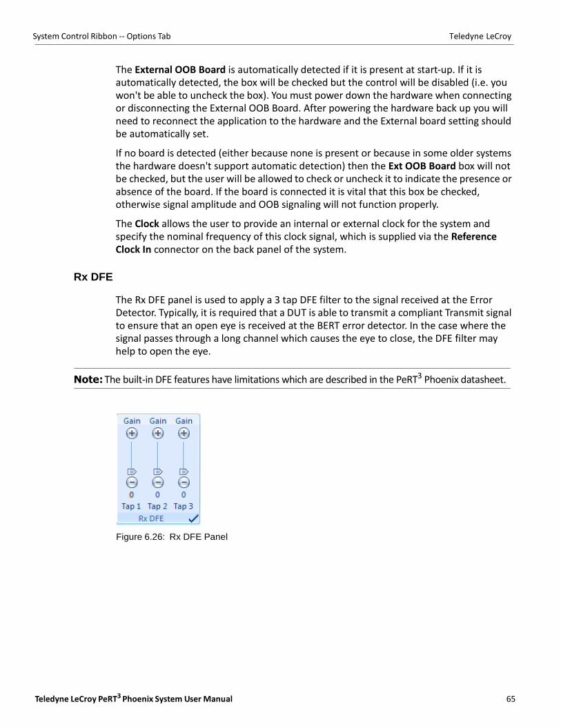
Teledyne LeCroy PeRT3 Phoenix System User Manual 65
System Control Ribbon ‐‐ Options Tab Teledyne LeCroy
The External OOB Board is automatically detected if it is present at start‐up. If it is automatically detected, the box will be checked but the control will be disabled (i.e. you won't be able to uncheck the box). You must power down the hardware when connecting or disconnecting the External OOB Board. After powering the hardware back up you will need to reconnect the application to the hardware and the External board setting should be automatically set.
If no board is detected (either because none is present or because in some older systems the hardware doesn't support automatic detection) then the Ext OOB Board box will not be checked, but the user will be allowed to check or uncheck it to indicate the presence or absence of the board. If the board is connected it is vital that this box be checked, otherwise signal amplitude and OOB signaling will not function properly.
The Clock allows the user to provide an internal or external clock for the system and specify the nominal frequency of this clock signal, which is supplied via the Reference Clock In connector on the back panel of the system.
Rx DFE
The Rx DFE panel is used to apply a 3 tap DFE filter to the signal received at the Error Detector. Typically, it is required that a DUT is able to transmit a compliant Transmit signal to ensure that an open eye is received at the BERT error detector. In the case where the signal passes through a long channel which causes the eye to close, the DFE filter may help to open the eye.
Note: The built‐in DFE features have limitations which are described in the PeRT3 Phoenix datasheet.
Figure 6.26: Rx DFE Panel
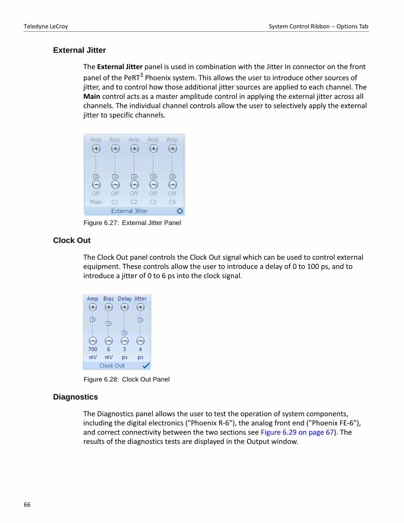
66
Teledyne LeCroy System Control Ribbon ‐‐ Options Tab
External Jitter
The External Jitter panel is used in combination with the Jitter In connector on the front
panel of the PeRT3 Phoenix system. This allows the user to introduce other sources of jitter, and to control how those additional jitter sources are applied to each channel. The Main control acts as a master amplitude control in applying the external jitter across all channels. The individual channel controls allow the user to selectively apply the external jitter to specific channels.
Figure 6.27: External Jitter Panel
Clock Out
The Clock Out panel controls the Clock Out signal which can be used to control external equipment. These controls allow the user to introduce a delay of 0 to 100 ps, and to introduce a jitter of 0 to 6 ps into the clock signal.
Figure 6.28: Clock Out Panel
Diagnostics
The Diagnostics panel allows the user to test the operation of system components, including the digital electronics ("Phoenix R‐6"), the analog front end ("Phoenix FE‐6"), and correct connectivity between the two sections see Figure 6.29 on page 67). The results of the diagnostics tests are displayed in the Output window.
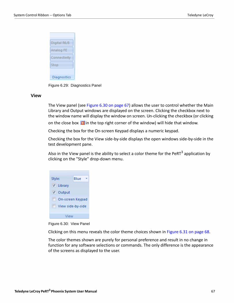
Teledyne LeCroy PeRT3 Phoenix System User Manual 67
System Control Ribbon ‐‐ Options Tab Teledyne LeCroy
Figure 6.29: Diagnostics Panel
View
The View panel (see Figure 6.30 on page 67) allows the user to control whether the Main Library and Output windows are displayed on the screen. Clicking the checkbox next to the window name will display the window on screen. Un‐clicking the checkbox (or clicking
on the close box in the top right corner of the window) will hide that window.
Checking the box for the On‐screen Keypad displays a numeric keypad.
Checking the box for the View side‐by‐side displays the open windows side‐by‐side in the test development pane.
Also in the View panel is the ability to select a color theme for the PeRT3 application by clicking on the "Style" drop‐down menu.
Figure 6.30: View Panel
Clicking on this menu reveals the color theme choices shown in Figure 6.31 on page 68.
The color themes shown are purely for personal preference and result in no change in function for any software selections or commands. The only difference is the appearance of the screens as displayed to the user.
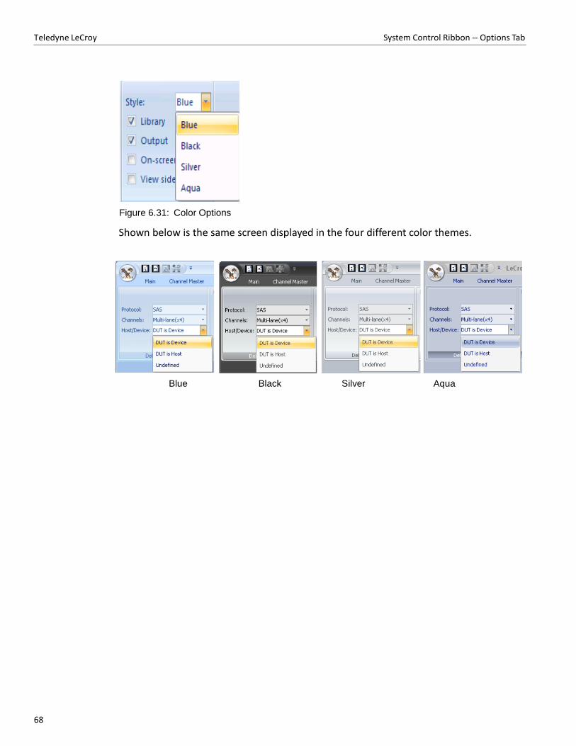
68
Teledyne LeCroy System Control Ribbon ‐‐ Options Tab
Figure 6.31: Color Options
Shown below is the same screen displayed in the four different color themes.
Blue Black Silver Aqua
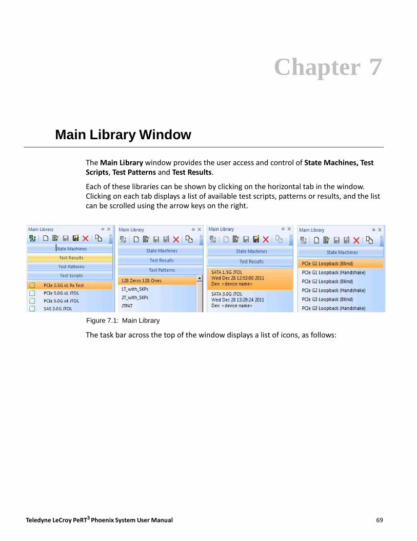
Teledyne LeCroy PeRT3 Phoenix System User Manual 69
Chapter 7
Main Library Window
The Main Library window provides the user access and control of State Machines, Test Scripts, Test Patterns and Test Results.
Each of these libraries can be shown by clicking on the horizontal tab in the window. Clicking on each tab displays a list of available test scripts, patterns or results, and the list can be scrolled using the arrow keys on the right.
Figure 7.1: Main Library
The task bar across the top of the window displays a list of icons, as follows:
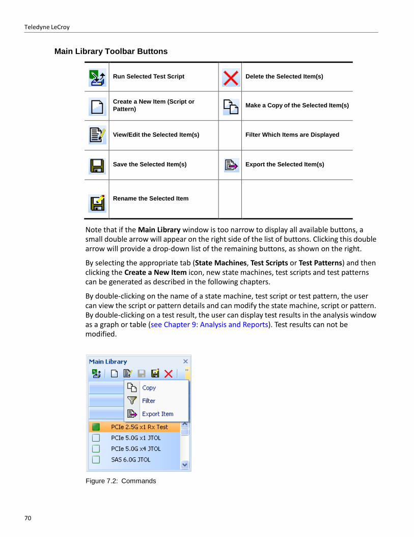
70
Teledyne LeCroy
Main Library Toolbar Buttons
Run Selected Test Script
Delete the Selected Item(s)
Create a New Item (Script or
Pattern)
Make a Copy of the Selected Item(s)
View/Edit the Selected Item(s)
Filter Which Items are Displayed
Save the Selected Item(s)
Export the Selected Item(s)
Rename the Selected Item
Note that if the Main Library window is too narrow to display all available buttons, a small double arrow will appear on the right side of the list of buttons. Clicking this double arrow will provide a drop‐down list of the remaining buttons, as shown on the right.
By selecting the appropriate tab (State Machines, Test Scripts or Test Patterns) and then clicking the Create a New Item icon, new state machines, test scripts and test patterns can be generated as described in the following chapters.
By double‐clicking on the name of a state machine, test script or test pattern, the user can view the script or pattern details and can modify the state machine, script or pattern. By double‐clicking on a test result, the user can display test results in the analysis window as a graph or table (see Chapter 9: Analysis and Reports). Test results can not be modified.
Figure 7.2: Commands
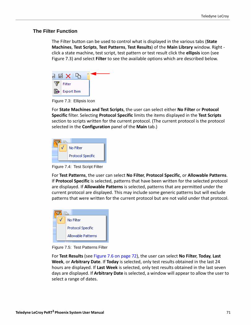
Teledyne LeCroy PeRT3 Phoenix System User Manual 71
Teledyne LeCroy
The Filter Function
The Filter button can be used to control what is displayed in the various tabs (State Machines, Test Scripts, Test Patterns, Test Results) of the Main Library window. Right ‐ click a state machine, test script, test pattern or test result click the ellipsis icon (see Figure 7.3) and select Filter to see the available options which are described below.
Figure 7.3: Ellipsis Icon
For State Machines and Test Scripts, the user can select either No Filter or Protocol Specific filter. Selecting Protocol Specific limits the items displayed in the Test Scripts section to scripts written for the current protocol. (The current protocol is the protocol selected in the Configuration panel of the Main tab.)
Figure 7.4: Test Script Filter
For Test Patterns, the user can select No Filter, Protocol Specific, or Allowable Patterns. If Protocol Specific is selected, patterns that have been written for the selected protocol are displayed. If Allowable Patterns is selected, patterns that are permitted under the current protocol are displayed. This may include some generic patterns but will exclude patterns that were written for the current protocol but are not valid under that protocol.
Figure 7.5: Test Patterns Filter
For Test Results (see Figure 7.6 on page 72), the user can select No Filter, Today, Last Week, or Arbitrary Date. If Today is selected, only test results obtained in the last 24 hours are displayed. If Last Week is selected, only test results obtained in the last seven days are displayed. If Arbitrary Date is selected, a window will appear to allow the user to select a range of dates.
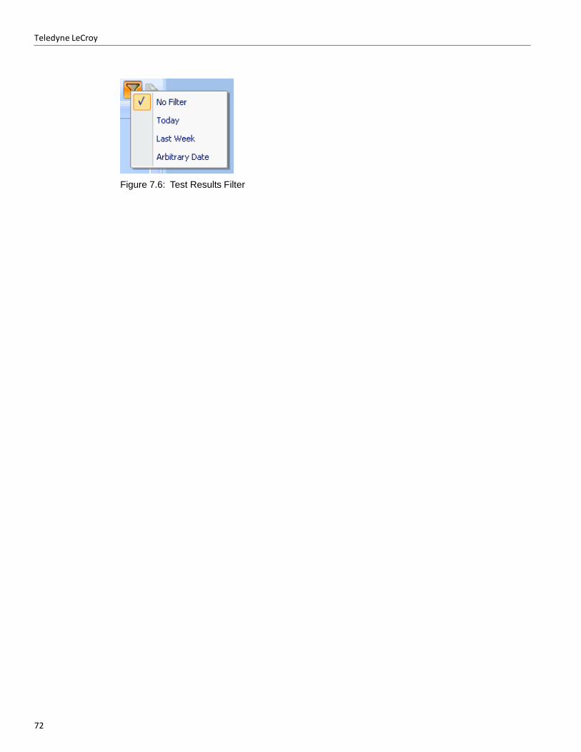
Teledyne LeCroy
72
Figure 7.6: Test Results Filter

Teledyne LeCroy PeRT3 Phoenix System User Manual 73
Chapter 8
Creating a New Test Script
A new test script can be created by first clicking on the Test Scripts tab in the Main Library
window, then clicking the Create a New Item icon Create a New Item.
Clicking this icon enters a new item in the list of test scripts (named by default "New Test
Suite"), and opens a window in the Test Development portion of the PeRT3 main
application window. This window fills the available area of the PeRT3 main application window below the System Control Ribbon. See Figure 8.1 below.
Note: By default, the Main Library window and the Output window are "docked" to the side and
bottom of the main application window, and the new Test Script window fills the remaining space. If either the Main Library or the Output windows are undocked and left floating, the new Test Script window will expand to fill that space, and portions of the Test Script window may be obscured by the floating window(s).
Figure 8.1: Main Application Window
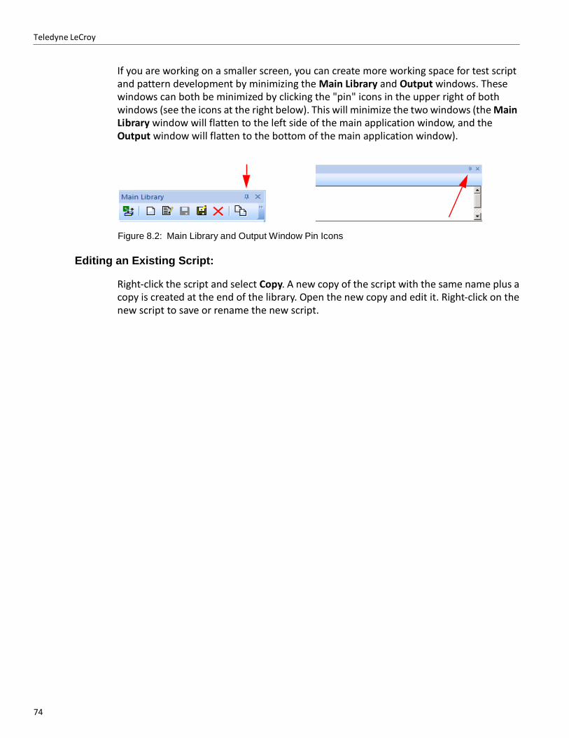
Teledyne LeCroy
74
If you are working on a smaller screen, you can create more working space for test script and pattern development by minimizing the Main Library and Output windows. These windows can both be minimized by clicking the "pin" icons in the upper right of both windows (see the icons at the right below). This will minimize the two windows (the Main Library window will flatten to the left side of the main application window, and the Output window will flatten to the bottom of the main application window).
Figure 8.2: Main Library and Output Window Pin Icons
Editing an Existing Script:
Right‐click the script and select Copy. A new copy of the script with the same name plus a copy is created at the end of the library. Open the new copy and edit it. Right‐click on the new script to save or rename the new script.
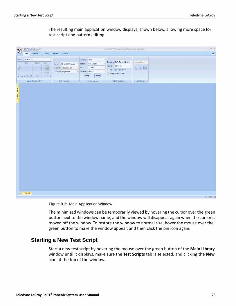
Starting a New Test Script Teledyne LeCroy
Teledyne LeCroy PeRT3 Phoenix System User Manual 75
The resulting main application window displays, shown below, allowing more space for test script and pattern editing.
Figure 8.3: Main Application Window
The minimized windows can be temporarily viewed by hovering the cursor over the green button next to the window name, and the window will disappear again when the cursor is moved off the window. To restore the window to normal size, hover the mouse over the green button to make the window appear, and then click the pin icon again.
Starting a New Test Script
Start a new test script by hovering the mouse over the green button of the Main Library window until it displays, make sure the Test Scripts tab is selected, and clicking the New icon at the top of the window.

76
Teledyne LeCroy Test Script Data Block
These actions display a main application window which looks as follows, providing more visible space for test script development.
Figure 8.4: Main Application Window Test Script Development Space
Test Script Data Block
The first block that appears in the new test script window is the header block, named Test Script Data. This block contains the Script Data tab, which contains three panels, Basic Data, Test Description and Device Description.
Figure 8.5: Test Script Data

Teledyne LeCroy PeRT3 Phoenix System User Manual 77
Test Script Data Block Teledyne LeCroy
Basic Data
The Basic Data panel allows the user to name the test script and identify the creator of the script by entering this information into the Script Name and Creator fields. The Script Name will be the name listed in the Main Library window, under the Test Scripts tab, whenever that window is displayed.
Figure 8.6: Basic Data Panel
Test Description
The Test Description panel allows the user to designated the Test Type (either Receiver Test or Production Test) and number of channels to be tested (from 1 to the maximum number supported by the system hardware). The channels tested will always start with Channel 1 (e.g., if two channels are selected on a system that supports four channels, the channels tested will be Channel 1 and Channel 2).
Figure 8.7: Test Description Panel
Device Description
The Device Description panel allows the user to specify the protocol to be used (options are SATA, SAS, PCIe, USB 3.0, Custom, Generator Only or Receiver Only) and the direction (DUT is Device, DUT is Host or Undefined).
Figure 8.8: Device Description Panel
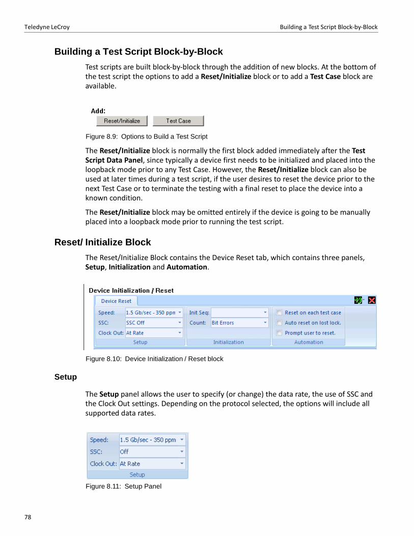
78
Teledyne LeCroy Building a Test Script Block‐by‐Block
Building a Test Script Block-by-Block
Test scripts are built block‐by‐block through the addition of new blocks. At the bottom of the test script the options to add a Reset/Initialize block or to add a Test Case block are available.
Figure 8.9: Options to Build a Test Script
The Reset/Initialize block is normally the first block added immediately after the Test Script Data Panel, since typically a device first needs to be initialized and placed into the loopback mode prior to any Test Case. However, the Reset/Initialize block can also be used at later times during a test script, if the user desires to reset the device prior to the next Test Case or to terminate the testing with a final reset to place the device into a known condition.
The Reset/Initialize block may be omitted entirely if the device is going to be manually placed into a loopback mode prior to running the test script.
Reset/ Initialize Block
The Reset/Initialize Block contains the Device Reset tab, which contains three panels, Setup, Initialization and Automation.
Figure 8.10: Device Initialization / Reset block
Setup
The Setup panel allows the user to specify (or change) the data rate, the use of SSC and the Clock Out settings. Depending on the protocol selected, the options will include all supported data rates.
Figure 8.11: Setup Panel
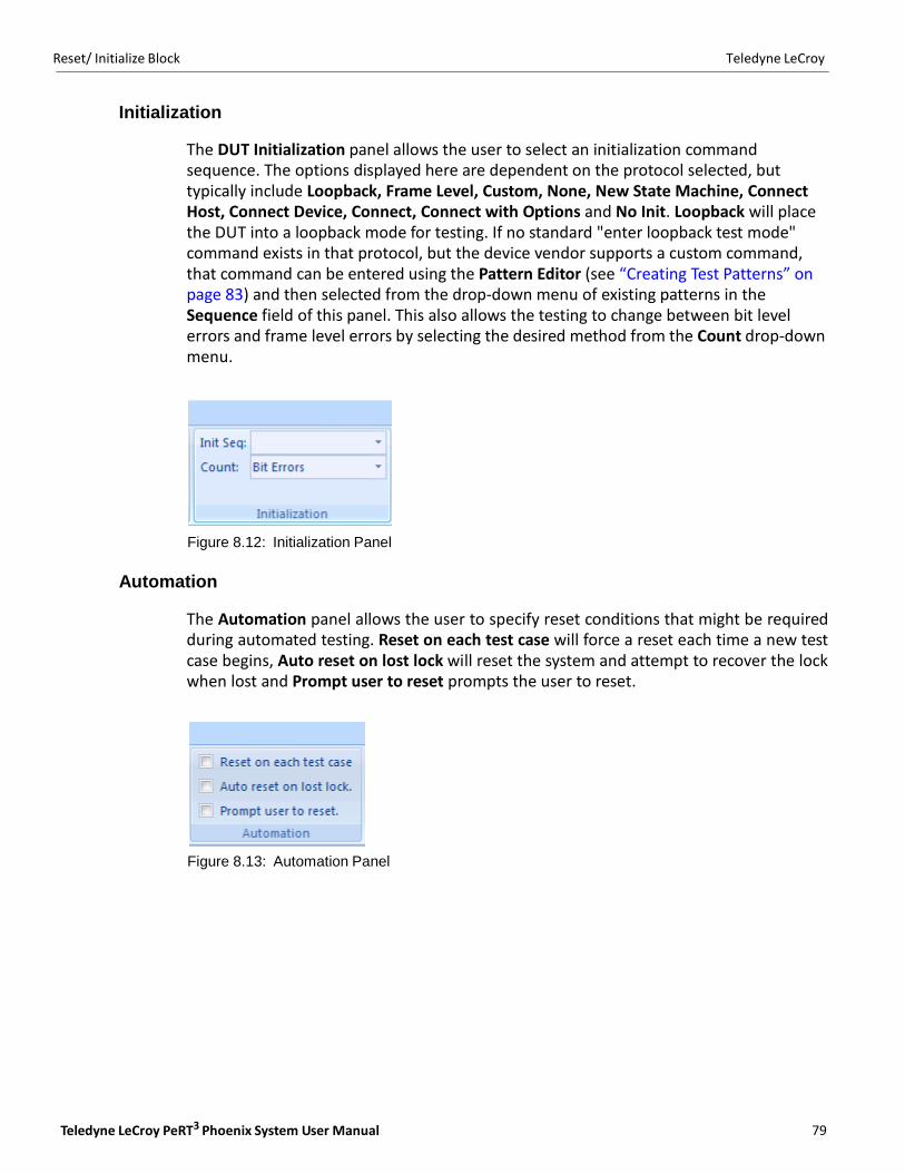
Teledyne LeCroy PeRT3 Phoenix System User Manual 79
Reset/ Initialize Block Teledyne LeCroy
Initialization
The DUT Initialization panel allows the user to select an initialization command sequence. The options displayed here are dependent on the protocol selected, but typically include Loopback, Frame Level, Custom, None, New State Machine, Connect Host, Connect Device, Connect, Connect with Options and No Init. Loopback will place the DUT into a loopback mode for testing. If no standard "enter loopback test mode" command exists in that protocol, but the device vendor supports a custom command, that command can be entered using the Pattern Editor (see “Creating Test Patterns” on page 83) and then selected from the drop‐down menu of existing patterns in the Sequence field of this panel. This also allows the testing to change between bit level errors and frame level errors by selecting the desired method from the Count drop‐down menu.
Figure 8.12: Initialization Panel
Automation
The Automation panel allows the user to specify reset conditions that might be required during automated testing. Reset on each test case will force a reset each time a new test case begins, Auto reset on lost lock will reset the system and attempt to recover the lock when lost and Prompt user to reset prompts the user to reset.
Figure 8.13: Automation Panel
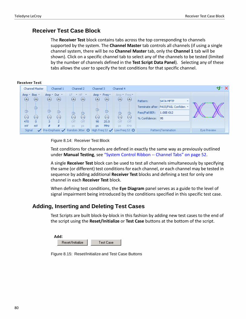
80
Teledyne LeCroy Receiver Test Case Block
Receiver Test Case Block
The Receiver Test block contains tabs across the top corresponding to channels supported by the system. The Channel Master tab controls all channels (if using a single channel system, there will be no Channel Master tab, only the Channel 1 tab will be shown). Click on a specific channel tab to select any of the channels to be tested (limited by the number of channels defined in the Test Script Data Panel). Selecting any of these tabs allows the user to specify the test conditions for that specific channel.
Figure 8.14: Receiver Test Block
Test conditions for channels are defined in exactly the same way as previously outlined under Manual Testing, see “System Control Ribbon ‐‐ Channel Tabs” on page 52.
A single Receiver Test block can be used to test all channels simultaneously by specifying the same (or different) test conditions for each channel, or each channel may be tested in sequence by adding additional Receiver Test blocks and defining a test for only one channel in each Receiver Test block.
When defining test conditions, the Eye Diagram panel serves as a guide to the level of signal impairment being introduced by the conditions specified in this specific test case.
Adding, Inserting and Deleting Test Cases
Test Scripts are built block‐by‐block in this fashion by adding new test cases to the end of the script using the Reset/Initialize or Test Case buttons at the bottom of the script.
Figure 8.15: Reset/Initialize and Test Case Buttons

Teledyne LeCroy PeRT3 Phoenix System User Manual 81
Adding, Inserting and Deleting Test Cases Teledyne LeCroy
New test cases can be inserted at any point in the test script by using the Insert Above
button which is located in the top left of each block. When this button is clicked, the menu shown below displays to allow you to insert either a Reset/Initialize block or a Receiver test case block. By default, the new test case is a copy of the existing test case.
Blocks can be deleted from the script by using the "Delete" button , also in the top right corner of each block.

Teledyne LeCroy Adding, Inserting and Deleting Test Cases
82
Teledyne LeCroy PeRT3 Phoenix System User Manual 83
Chapter 9
Creating Test Patterns
The PeRT3 Phoenix System includes a library of predefined test patterns, that for many users may fully satisfy their requirements.
Some users may wish to create additional test patterns or to modify the patterns supplied with the system. A simple example of the need to create a test pattern is when the user’s device has a vendor‐specific command which is required to place the device into a test loopback mode. In this case, the vendor‐specific command can be created using the Pattern Editor and then selected in the DUT Initialization panel of the Main tab in the System Control Ribbon (see “DUT Initialization” on page 50).
Creating a New Test Pattern
A new test pattern can be created by clicking on the Test Patterns tab in the Main Library
window, then clicking the Create New Item icon in the task bar.
When a new test pattern is created, it has certain default characteristics which are determined by the Default Settings which are currently set for the system. To change the Default Settings, click the Options tab on the System Control Ribbon and select the desired values in the Default Settings panel.If the default settings are not desired, they can easily be changed by, for example, selecting a different protocol in the Decode As field of the Display Mode panel of the Pattern tab.
It is important to have the Decode As field set to the correct protocol for the pattern you are defining. Not only does this dictate how the pattern is displayed in the pattern editor, it also controls how it is sorted and displayed in the pattern picker. When the Create New
Item icon is clicked, a Pattern Editor window displays within the PeRT3 main application window below the System Control Ribbon. The Pattern Editor window has two sections: the upper section displays the actual data pattern being created, and the lower section displays the current data decoded as a protocol primitive or frame using the protocol selected in the Decode As field.
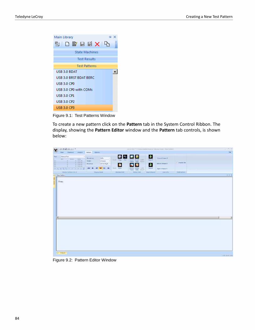
84
Teledyne LeCroy Creating a New Test Pattern
Figure 9.1: Test Patterns Window
To create a new pattern click on the Pattern tab in the System Control Ribbon. The display, showing the Pattern Editor window and the Pattern tab controls, is shown below:
Figure 9.2: Pattern Editor Window
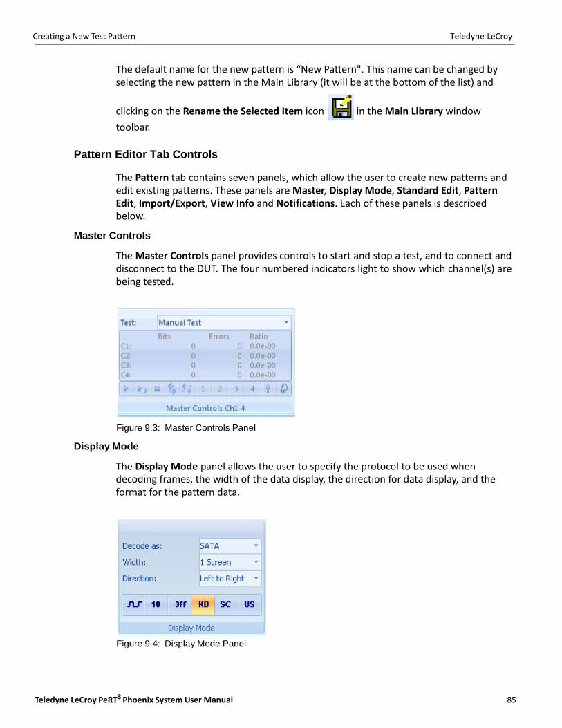
Teledyne LeCroy PeRT3 Phoenix System User Manual 85
Creating a New Test Pattern Teledyne LeCroy
The default name for the new pattern is “New Pattern". This name can be changed by selecting the new pattern in the Main Library (it will be at the bottom of the list) and
clicking on the Rename the Selected Item icon in the Main Library window
toolbar.
Pattern Editor Tab Controls
The Pattern tab contains seven panels, which allow the user to create new patterns and edit existing patterns. These panels are Master, Display Mode, Standard Edit, Pattern Edit, Import/Export, View Info and Notifications. Each of these panels is described below.
Master Controls
The Master Controls panel provides controls to start and stop a test, and to connect and disconnect to the DUT. The four numbered indicators light to show which channel(s) are being tested.
Figure 9.3: Master Controls Panel
Display Mode
The Display Mode panel allows the user to specify the protocol to be used when decoding frames, the width of the data display, the direction for data display, and the format for the pattern data.
Figure 9.4: Display Mode Panel
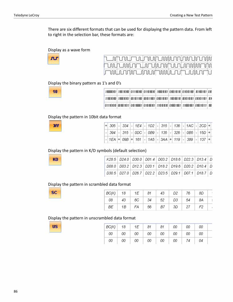
86
Teledyne LeCroy Creating a New Test Pattern
There are six different formats that can be used for displaying the pattern data. From left to right in the selection bar, these formats are:
Display as a wave form
Display the binary pattern as 1’s and 0’s
Display the pattern in 10bit data format
Display the pattern in K/D symbols (default selection)
Display the pattern in scrambled data format
Display the pattern in unscrambled data format
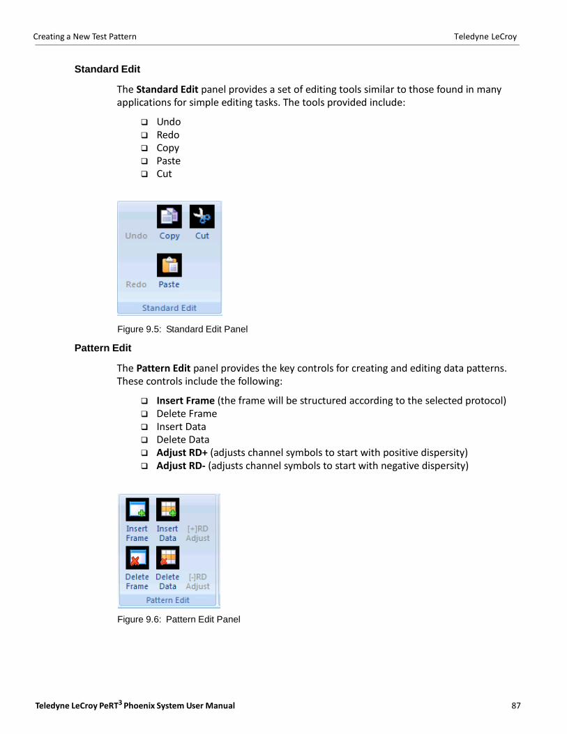
Teledyne LeCroy PeRT3 Phoenix System User Manual 87
Creating a New Test Pattern Teledyne LeCroy
Standard Edit
The Standard Edit panel provides a set of editing tools similar to those found in many applications for simple editing tasks. The tools provided include:
Undo Redo Copy Paste Cut
Figure 9.5: Standard Edit Panel
Pattern Edit
The Pattern Edit panel provides the key controls for creating and editing data patterns. These controls include the following:
Insert Frame (the frame will be structured according to the selected protocol) Delete Frame Insert Data Delete Data Adjust RD+ (adjusts channel symbols to start with positive dispersity) Adjust RD‐ (adjusts channel symbols to start with negative dispersity)
Figure 9.6: Pattern Edit Panel
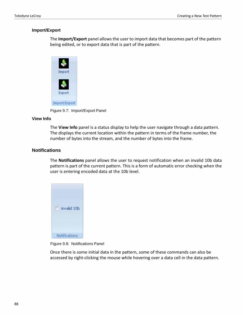
88
Teledyne LeCroy Creating a New Test Pattern
Import/Export
The Import/Export panel allows the user to import data that becomes part of the pattern being edited, or to export data that is part of the pattern.
Figure 9.7: Import/Export Panel
View Info
The View Info panel is a status display to help the user navigate through a data pattern. The displays the current location within the pattern in terms of the frame number, the number of bytes into the stream, and the number of bytes into the frame.
Notifications
The Notifications panel allows the user to request notification when an invalid 10b data pattern is part of the current pattern. This is a form of automatic error checking when the user is entering encoded data at the 10b level.
Figure 9.8: Notifications Panel
Once there is some initial data in the pattern, some of these commands can also be accessed by right‐clicking the mouse while hovering over a data cell in the data pattern.
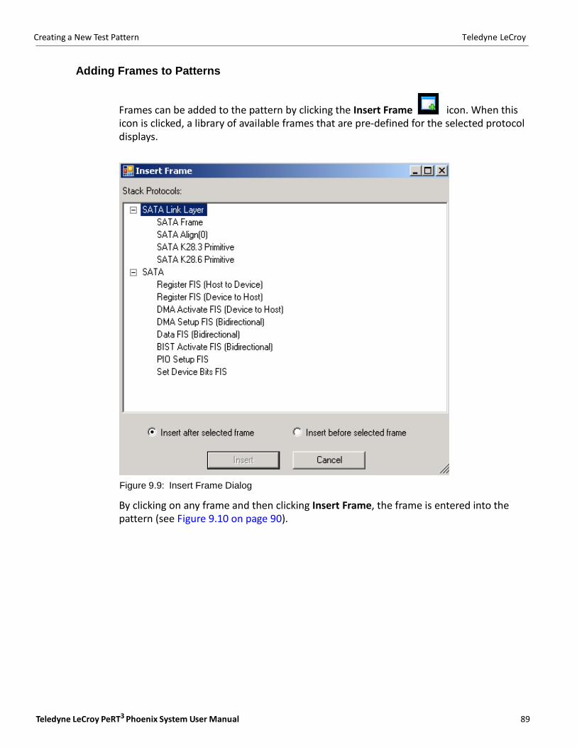
Teledyne LeCroy PeRT3 Phoenix System User Manual 89
Creating a New Test Pattern Teledyne LeCroy
Adding Frames to Patterns
Frames can be added to the pattern by clicking the Insert Frame icon. When this icon is clicked, a library of available frames that are pre‐defined for the selected protocol displays.
Figure 9.9: Insert Frame Dialog
By clicking on any frame and then clicking Insert Frame, the frame is entered into the pattern (see Figure 9.10 on page 90).
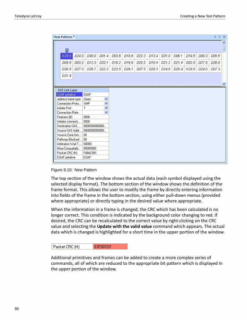
90
Teledyne LeCroy Creating a New Test Pattern
Figure 9.10: New Pattern
The top section of the window shows the actual data (each symbol displayed using the selected display format). The bottom section of the window shows the definition of the frame format. This allows the user to modify the frame by directly entering information into fields of the frame in the bottom section, using either pull‐down menus (provided where appropriate) or directly typing in the desired value where appropriate.
When the information in a frame is changed, the CRC which has been calculated is no longer correct. This condition is indicated by the background color changing to red. If desired, the CRC can be recalculated to the correct value by right‐clicking on the CRC value and selecting the Update with the valid value command which appears. The actual data which is changed is highlighted for a short time in the upper portion of the window.
Additional primitives and frames can be added to create a more complex series of commands, all of which are reduced to the appropriate bit pattern which is displayed in the upper portion of the window.
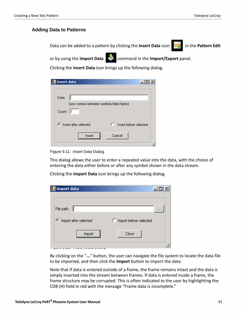
Teledyne LeCroy PeRT3 Phoenix System User Manual 91
Creating a New Test Pattern Teledyne LeCroy
Figure 9.12: Import Data Dialog
Adding Data to Patterns
Data can be added to a pattern by clicking the Insert Data icon in the Pattern Edit
or by using the Import Data command in the Import/Export panel.
Clicking the Insert Data icon brings up the following dialog.
Figure 9.11: Insert Data Dialog
This dialog allows the user to enter a repeated value into the data, with the choice of entering the data either before or after any symbol shown in the data stream.
Clicking the Import Data icon brings up the following dialog.
By clicking on the "..." button, the user can navigate the file system to locate the data file to be imported, and then click the Import button to import the data.
Note that if data is entered outside of a frame, the frame remains intact and the data is simply inserted into the stream between frames. If data is entered inside a frame, the frame structure may be corrupted. This is often indicated to the user by highlighting the CDB (H) field in red with the message “Frame data is incomplete.”

92
Teledyne LeCroy Creating a New Test Pattern
Modifying Data Within a Pattern
The data pattern can be modified directly by double‐clicking on the data cell in the top containing that value, then typing in the new value. If in Waveform, Binary (10), KD or 10bit (3FF) mode, the new value can be entered directly into the cell. If in SC or US mode, the user can type the new K‐code or D‐code values directly into the cell, or use the drop‐ down menu to get a list of valid values.
Again, if the data is located within a frame, modifications may render the CRC invalid or may corrupt the frame. This will be indicated by the frame summary in the bottom half of the window.
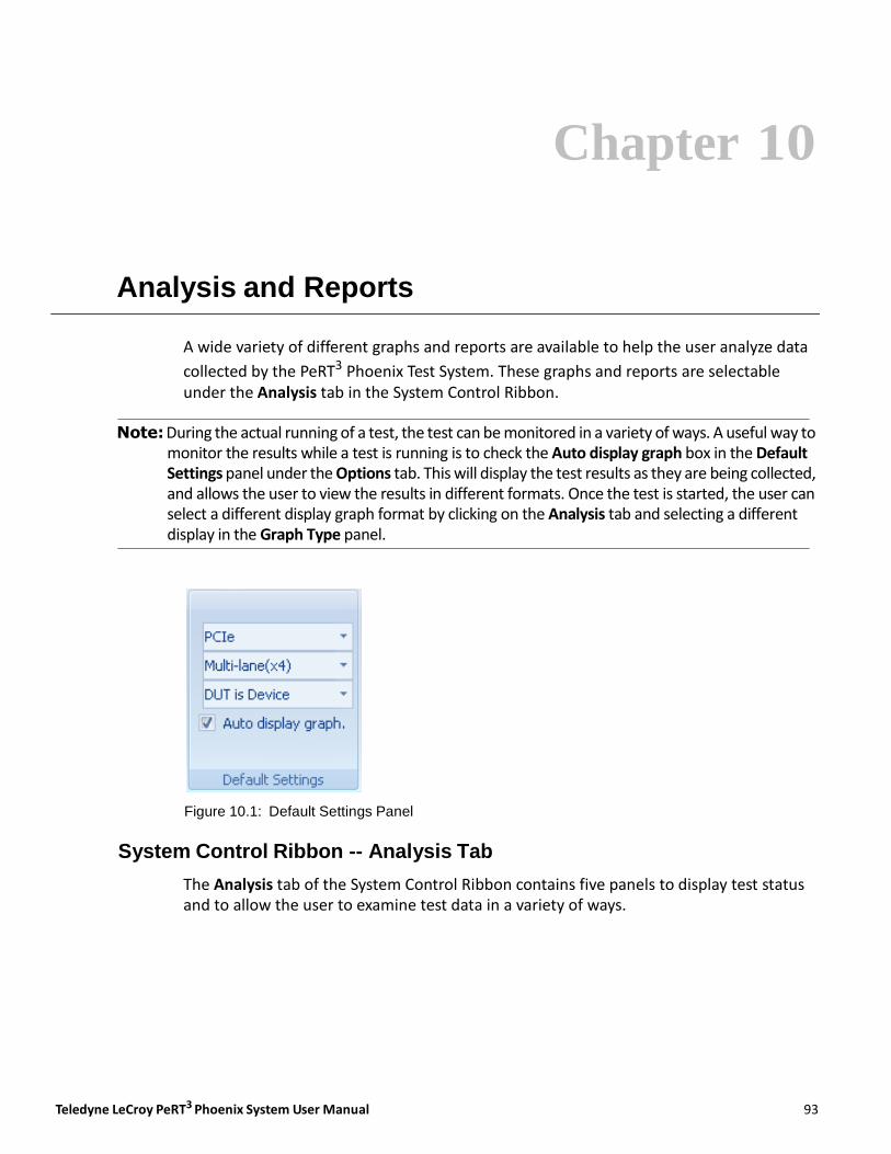
Teledyne LeCroy PeRT3 Phoenix System User Manual 93
Chapter 10
Analysis and Reports
A wide variety of different graphs and reports are available to help the user analyze data
collected by the PeRT3 Phoenix Test System. These graphs and reports are selectable under the Analysis tab in the System Control Ribbon.
Note: During the actual running of a test, the test can be monitored in a variety of ways. A useful way to
monitor the results while a test is running is to check the Auto display graph box in the Default Settings panel under the Options tab. This will display the test results as they are being collected, and allows the user to view the results in different formats. Once the test is started, the user can select a different display graph format by clicking on the Analysis tab and selecting a different display in the Graph Type panel.
Figure 10.1: Default Settings Panel
System Control Ribbon -- Analysis Tab
The Analysis tab of the System Control Ribbon contains five panels to display test status and to allow the user to examine test data in a variety of ways.
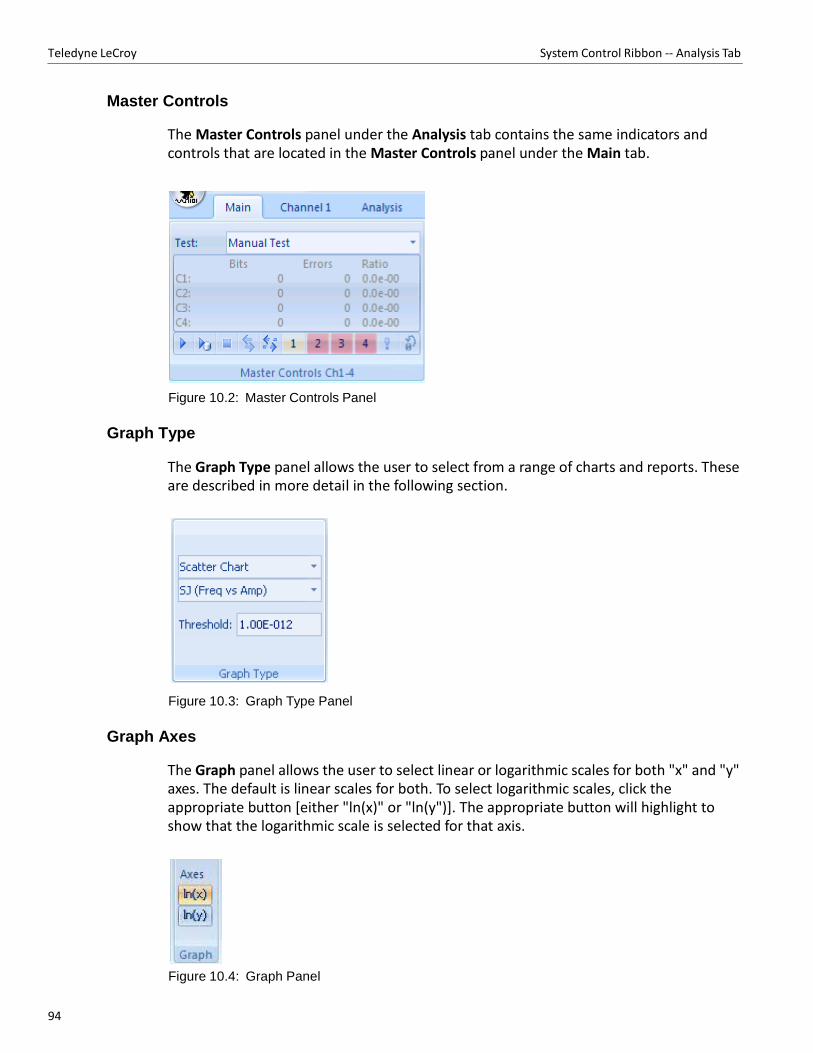
94
Teledyne LeCroy System Control Ribbon ‐‐ Analysis Tab
Master Controls
The Master Controls panel under the Analysis tab contains the same indicators and controls that are located in the Master Controls panel under the Main tab.
Figure 10.2: Master Controls Panel
Graph Type
The Graph Type panel allows the user to select from a range of charts and reports. These are described in more detail in the following section.
Figure 10.3: Graph Type Panel
Graph Axes
The Graph panel allows the user to select linear or logarithmic scales for both "x" and "y" axes. The default is linear scales for both. To select logarithmic scales, click the appropriate button [either "ln(x)" or "ln(y")]. The appropriate button will highlight to show that the logarithmic scale is selected for that axis.
Figure 10.4: Graph Panel
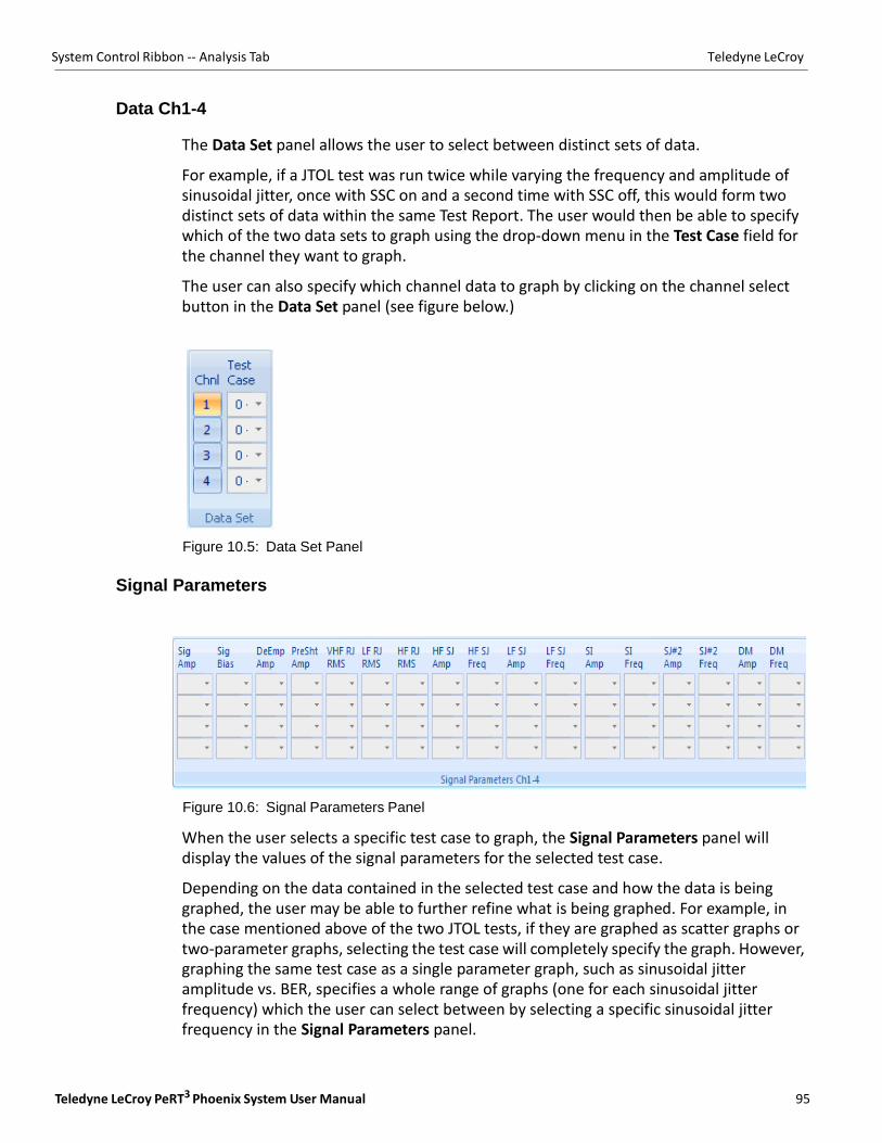
Teledyne LeCroy PeRT3 Phoenix System User Manual 95
System Control Ribbon ‐‐ Analysis Tab Teledyne LeCroy
Data Ch1-4
The Data Set panel allows the user to select between distinct sets of data.
For example, if a JTOL test was run twice while varying the frequency and amplitude of sinusoidal jitter, once with SSC on and a second time with SSC off, this would form two distinct sets of data within the same Test Report. The user would then be able to specify which of the two data sets to graph using the drop‐down menu in the Test Case field for the channel they want to graph.
The user can also specify which channel data to graph by clicking on the channel select button in the Data Set panel (see figure below.)
Figure 10.5: Data Set Panel
Signal Parameters
Figure 10.6: Signal Parameters Panel
When the user selects a specific test case to graph, the Signal Parameters panel will display the values of the signal parameters for the selected test case.
Depending on the data contained in the selected test case and how the data is being graphed, the user may be able to further refine what is being graphed. For example, in the case mentioned above of the two JTOL tests, if they are graphed as scatter graphs or two‐parameter graphs, selecting the test case will completely specify the graph. However, graphing the same test case as a single parameter graph, such as sinusoidal jitter amplitude vs. BER, specifies a whole range of graphs (one for each sinusoidal jitter frequency) which the user can select between by selecting a specific sinusoidal jitter frequency in the Signal Parameters panel.
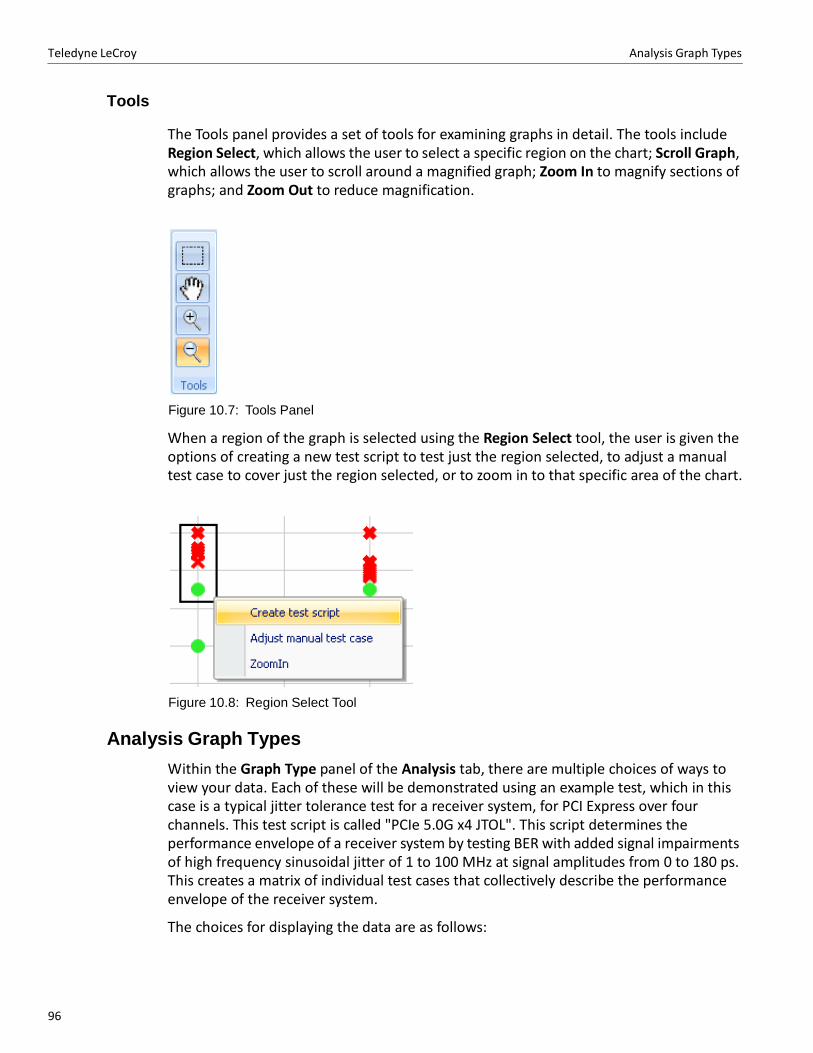
96
Teledyne LeCroy Analysis Graph Types
Tools
The Tools panel provides a set of tools for examining graphs in detail. The tools include Region Select, which allows the user to select a specific region on the chart; Scroll Graph, which allows the user to scroll around a magnified graph; Zoom In to magnify sections of graphs; and Zoom Out to reduce magnification.
Figure 10.7: Tools Panel
When a region of the graph is selected using the Region Select tool, the user is given the options of creating a new test script to test just the region selected, to adjust a manual test case to cover just the region selected, or to zoom in to that specific area of the chart.
Figure 10.8: Region Select Tool
Analysis Graph Types
Within the Graph Type panel of the Analysis tab, there are multiple choices of ways to view your data. Each of these will be demonstrated using an example test, which in this case is a typical jitter tolerance test for a receiver system, for PCI Express over four channels. This test script is called "PCIe 5.0G x4 JTOL". This script determines the performance envelope of a receiver system by testing BER with added signal impairments of high frequency sinusoidal jitter of 1 to 100 MHz at signal amplitudes from 0 to 180 ps. This creates a matrix of individual test cases that collectively describe the performance envelope of the receiver system.
The choices for displaying the data are as follows:
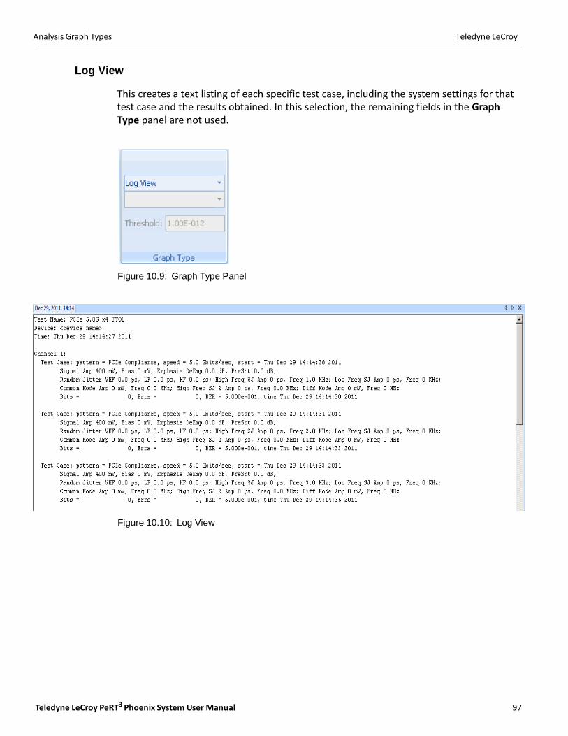
Teledyne LeCroy PeRT3 Phoenix System User Manual 97
Analysis Graph Types Teledyne LeCroy
Log View
This creates a text listing of each specific test case, including the system settings for that test case and the results obtained. In this selection, the remaining fields in the Graph Type panel are not used.
Figure 10.9: Graph Type Panel
Figure 10.10: Log View
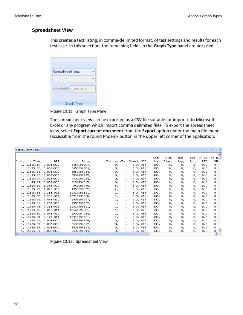
98
Teledyne LeCroy Analysis Graph Types
Spreadsheet View
This creates a text listing, in comma‐delimited format, of test settings and results for each test case. In this selection, the remaining fields in the Graph Type panel are not used.
Figure 10.11: Graph Type Panel
The spreadsheet view can be exported as a CSV file suitable for import into Microsoft Excel or any program which import comma delimited files. To export the spreadsheet view, select Export current document from the Export option under the main file menu (accessible from the round Phoenix button in the upper left corner of the application.
Figure 10.12: Spreadsheet View
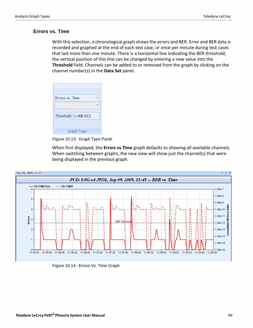
Teledyne LeCroy PeRT3 Phoenix System User Manual 99
Analysis Graph Types Teledyne LeCroy
Errors vs. Time
With this selection, a chronological graph shows the errors and BER. Error and BER data is recorded and graphed at the end of each test case, or once per minute during test cases that last more than one minute. There is a horizontal line indicating the BER threshold; the vertical position of this line can be changed by entering a new value into the Threshold field. Channels can be added to or removed from the graph by clicking on the channel number(s) in the Data Set panel.
Figure 10.13: Graph Type Panel
When first displayed, the Errors vs Time graph defaults to showing all available channels. When switching between graphs, the new view will show just the channel(s) that were being displayed in the previous graph.
Figure 10.14: Errors Vs. Time Graph
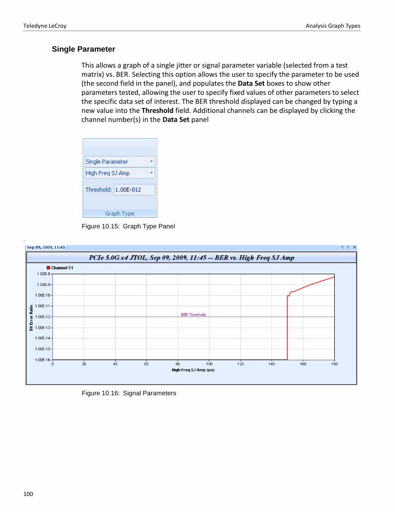
Teledyne LeCroy Analysis Graph Types
100100
Single Parameter
This allows a graph of a single jitter or signal parameter variable (selected from a test matrix) vs. BER. Selecting this option allows the user to specify the parameter to be used (the second field in the panel), and populates the Data Set boxes to show other parameters tested, allowing the user to specify fixed values of other parameters to select the specific data set of interest. The BER threshold displayed can be changed by typing a new value into the Threshold field. Additional channels can be displayed by clicking the channel number(s) in the Data Set panel
Figure 10.15: Graph Type Panel
.
Figure 10.16: Signal Parameters
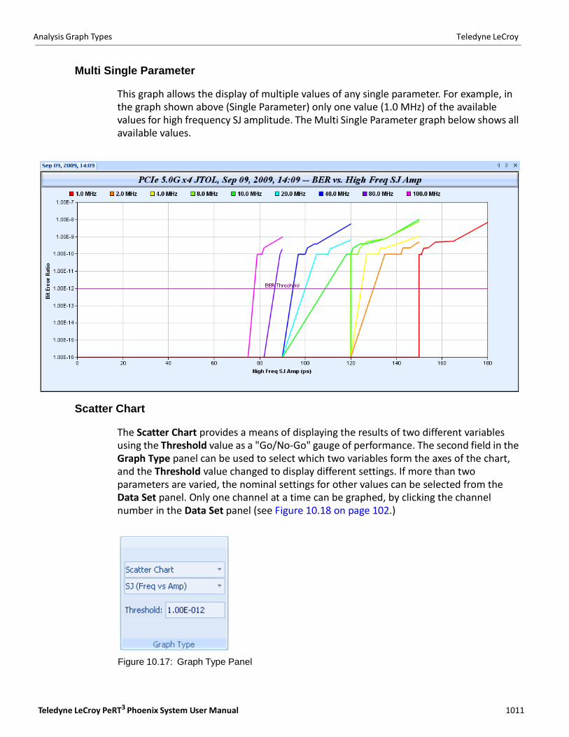
Analysis Graph Types Teledyne LeCroy
Teledyne LeCroy PeRT3 Phoenix System User Manual 101101
Multi Single Parameter
This graph allows the display of multiple values of any single parameter. For example, in the graph shown above (Single Parameter) only one value (1.0 MHz) of the available values for high frequency SJ amplitude. The Multi Single Parameter graph below shows all available values.
Scatter Chart
The Scatter Chart provides a means of displaying the results of two different variables using the Threshold value as a "Go/No‐Go" gauge of performance. The second field in the Graph Type panel can be used to select which two variables form the axes of the chart, and the Threshold value changed to display different settings. If more than two parameters are varied, the nominal settings for other values can be selected from the Data Set panel. Only one channel at a time can be graphed, by clicking the channel number in the Data Set panel (see Figure 10.18 on page 102.)
Figure 10.17: Graph Type Panel
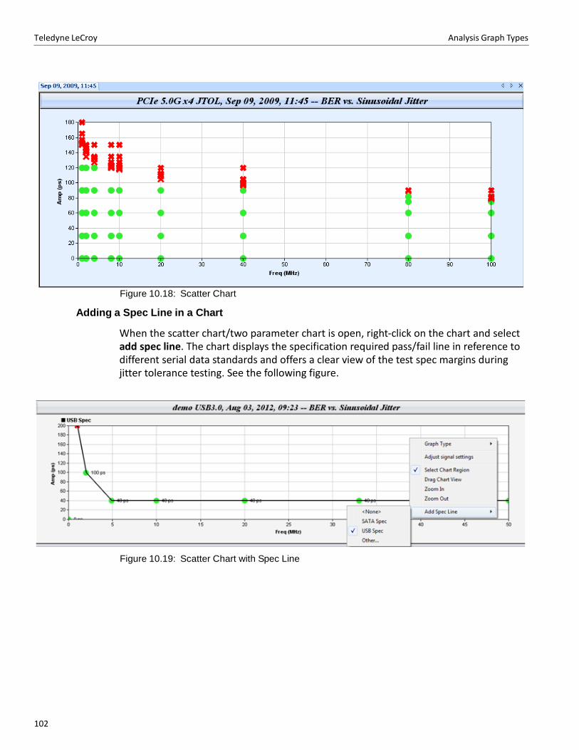
Teledyne LeCroy Analysis Graph Types
102102
Figure 10.18: Scatter Chart
Adding a Spec Line in a Chart
When the scatter chart/two parameter chart is open, right‐click on the chart and select add spec line. The chart displays the specification required pass/fail line in reference to different serial data standards and offers a clear view of the test spec margins during jitter tolerance testing. See the following figure.
Figure 10.19: Scatter Chart with Spec Line
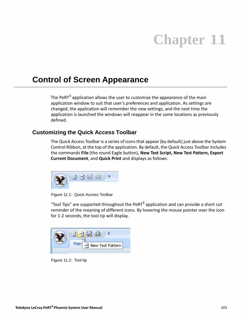
Teledyne LeCroy PeRT3 Phoenix System User Manual 103103
Chapter 11
Control of Screen Appearance
The PeRT3 application allows the user to customize the appearance of the main application window to suit that user’s preferences and application. As settings are changed, the application will remember the new settings, and the next time the application is launched the windows will reappear in the same locations as previously defined.
Customizing the Quick Access Toolbar
The Quick Access Toolbar is a series of icons that appear (by default) just above the System Control Ribbon, at the top of the application. By default, the Quick Access Toolbar includes the commands File (the round Eagle button), New Test Script, New Test Pattern, Export Current Document, and Quick Print and displays as follows.
Figure 11.1: Quick Access Toolbar
"Tool Tips" are supported throughout the PeRT3 application and can provide a short cut reminder of the meaning of different icons. By hovering the mouse pointer over the icon for 1‐2 seconds, the tool tip will display.
Figure 11.2: Tool tip
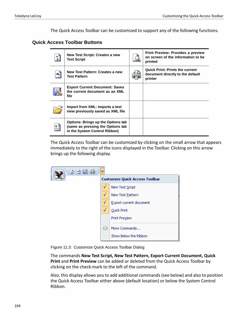
104104
Teledyne LeCroy Customizing the Quick Access Toolbar
The Quick Access Toolbar can be customized to support any of the following functions.
Quick Access Toolbar Buttons
New Test Script: Creates a new
Test Script
Print Preview: Provides a preview
on screen of the information to be
printed
New Test Pattern: Creates a new
Test Pattern
Quick Print: Prints the current
document directly to the default
printer
Export Current Document: Saves
the current document as an XML
file
Import from XML: Imports a test
view previously saved as XML file
Options: Brings up the Options tab
(same as pressing the Options tab
in the System Control Ribbon)
The Quick Access Toolbar can be customized by clicking on the small arrow that appears immediately to the right of the icons displayed in the Toolbar. Clicking on this arrow brings up the following display.
Figure 11.3: Customize Quick Access Toolbar Dialog
The commands New Test Script, New Test Pattern, Export Current Document, Quick Print and Print Preview can be added or deleted from the Quick Access Toolbar by clicking on the check‐mark to the left of the command.
Also, this display allows you to add additional commands (see below) and also to position the Quick Access Toolbar either above (default location) or below the System Control Ribbon.
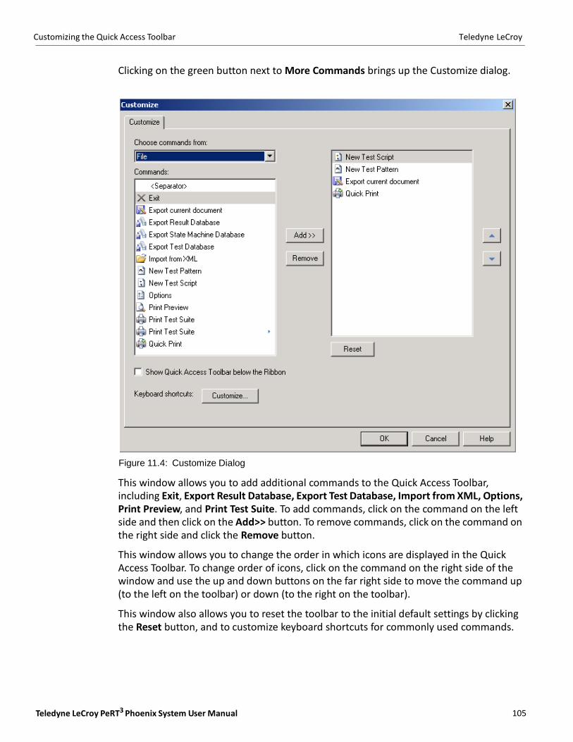
Teledyne LeCroy PeRT3 Phoenix System User Manual 105105
Customizing the Quick Access Toolbar Teledyne LeCroy
Clicking on the green button next to More Commands brings up the Customize dialog.
Figure 11.4: Customize Dialog
This window allows you to add additional commands to the Quick Access Toolbar, including Exit, Export Result Database, Export Test Database, Import from XML, Options, Print Preview, and Print Test Suite. To add commands, click on the command on the left side and then click on the Add>> button. To remove commands, click on the command on the right side and click the Remove button.
This window allows you to change the order in which icons are displayed in the Quick Access Toolbar. To change order of icons, click on the command on the right side of the window and use the up and down buttons on the far right side to move the command up (to the left on the toolbar) or down (to the right on the toolbar).
This window also allows you to reset the toolbar to the initial default settings by clicking the Reset button, and to customize keyboard shortcuts for commonly used commands.
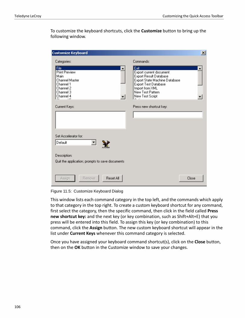
106106
Teledyne LeCroy Customizing the Quick Access Toolbar
To customize the keyboard shortcuts, click the Customize button to bring up the following window.
Figure 11.5: Customize Keyboard Dialog
This window lists each command category in the top left, and the commands which apply to that category in the top right. To create a custom keyboard shortcut for any command, first select the category, then the specific command, then click in the field called Press new shortcut key: and the next key (or key combination, such as Shift+Alt+E) that you press will be entered into this field. To assign this key (or key combination) to this command, click the Assign button. The new custom keyboard shortcut will appear in the list under Current Keys whenever this command category is selected.
Once you have assigned your keyboard command shortcut(s), click on the Close button, then on the OK button in the Customize window to save your changes.
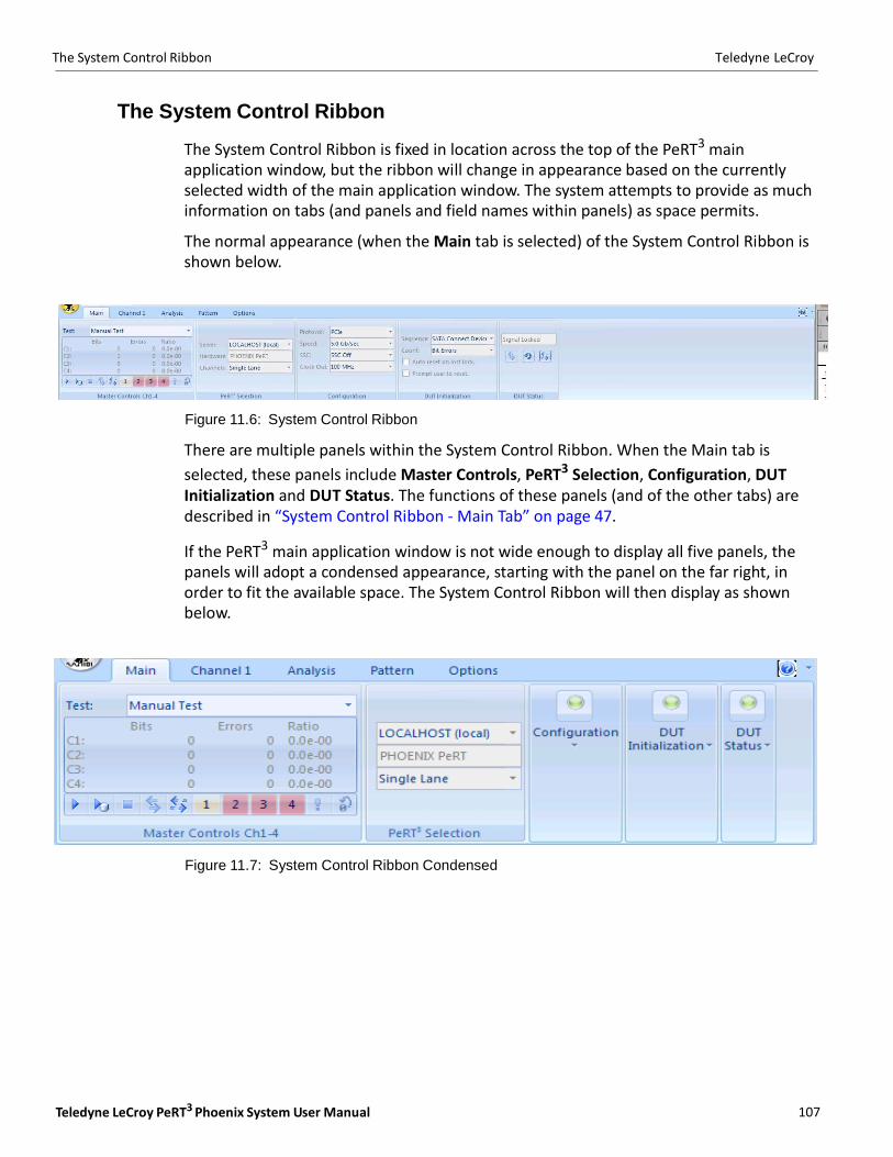
Teledyne LeCroy PeRT3 Phoenix System User Manual 107107
The System Control Ribbon Teledyne LeCroy
The System Control Ribbon
The System Control Ribbon is fixed in location across the top of the PeRT3 main application window, but the ribbon will change in appearance based on the currently selected width of the main application window. The system attempts to provide as much information on tabs (and panels and field names within panels) as space permits.
The normal appearance (when the Main tab is selected) of the System Control Ribbon is shown below.
Figure 11.6: System Control Ribbon
There are multiple panels within the System Control Ribbon. When the Main tab is
selected, these panels include Master Controls, PeRT3 Selection, Configuration, DUT Initialization and DUT Status. The functions of these panels (and of the other tabs) are described in “System Control Ribbon ‐ Main Tab” on page 47.
If the PeRT3 main application window is not wide enough to display all five panels, the panels will adopt a condensed appearance, starting with the panel on the far right, in order to fit the available space. The System Control Ribbon will then display as shown below.
Figure 11.7: System Control Ribbon Condensed

108108
Teledyne LeCroy Customizing the Main Library and Output Windows
To access any of the condensed panels, click on the green button that displays in the condensed and the full panel will display.
Figure 11.8: Accessing Condensed Panels
Commands and fields available within that panel can then be accessed, and the panel will re‐condense if the green button is pressed again or if you click anywhere outside the area of the expanded panel.
Customizing the Main Library and Output Windows
As noted in the overall description of the user interface, there are additional windows
which appear in the PeRT3 application. These include the Main Library and Output windows. The functions of these windows are described in detail in “Main Library Window” on page 69 and “Analysis and Reports” on page 93.
The Main Library window (see Figure 11.9 on page 109) displays by default "docked" to the lower left edge of the main application window, stretching from the bottom of the main application window to the bottom of the System Control Ribbon. This window can be dragged off to create a "floating window" and can then be repositioned anywhere on the user’s screen.
The Output window provides a log file of events during a test, and appears as shown below. By default, the Output window is docked to the bottom of the main application window, but as with the Main Library window, the Output window can be dragged to a new location to create a floating window.
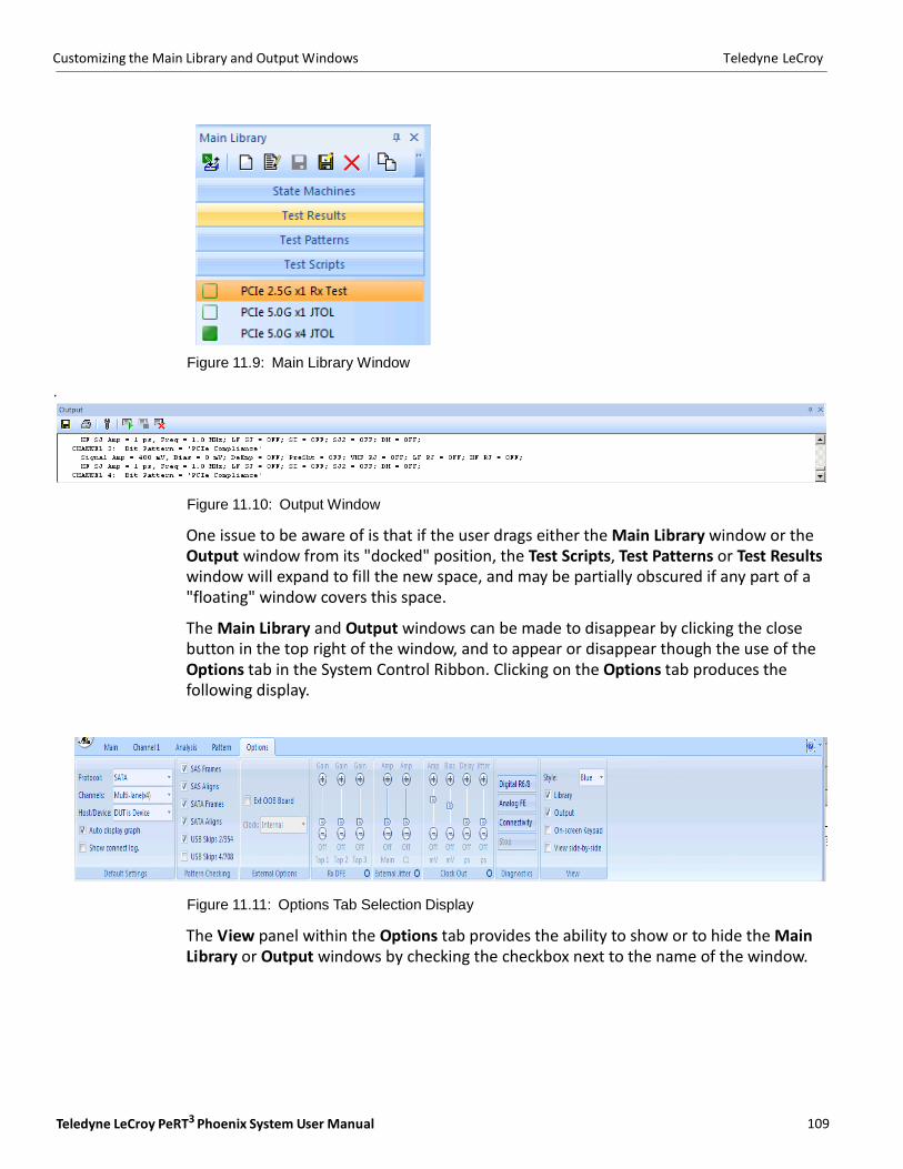
Teledyne LeCroy PeRT3 Phoenix System User Manual 109109
Customizing the Main Library and Output Windows Teledyne LeCroy
Figure 11.9: Main Library Window
.
Figure 11.10: Output Window
One issue to be aware of is that if the user drags either the Main Library window or the Output window from its "docked" position, the Test Scripts, Test Patterns or Test Results window will expand to fill the new space, and may be partially obscured if any part of a "floating" window covers this space.
The Main Library and Output windows can be made to disappear by clicking the close button in the top right of the window, and to appear or disappear though the use of the Options tab in the System Control Ribbon. Clicking on the Options tab produces the following display.
Figure 11.11: Options Tab Selection Display
The View panel within the Options tab provides the ability to show or to hide the Main Library or Output windows by checking the checkbox next to the name of the window.
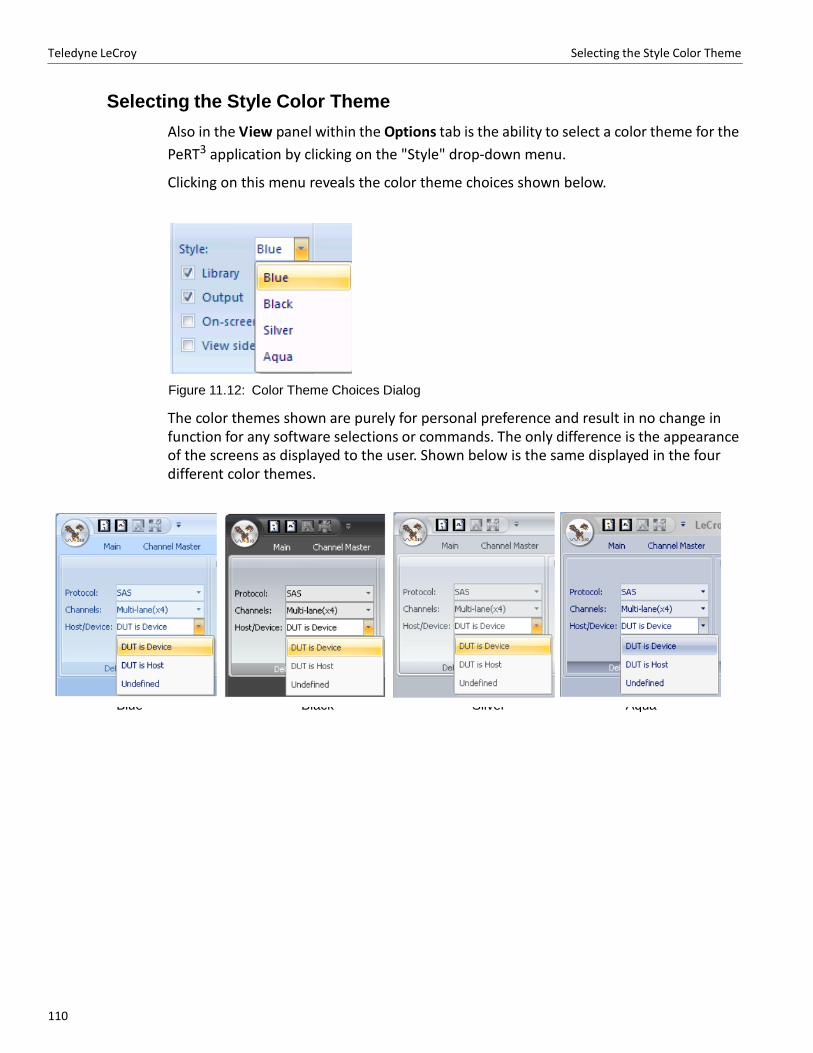
Teledyne LeCroy Selecting the Style Color Theme
110110
Blue Black Silver Aqua
Selecting the Style Color Theme
Also in the View panel within the Options tab is the ability to select a color theme for the
PeRT3 application by clicking on the "Style" drop‐down menu.
Clicking on this menu reveals the color theme choices shown below.
Figure 11.12: Color Theme Choices Dialog
The color themes shown are purely for personal preference and result in no change in function for any software selections or commands. The only difference is the appearance of the screens as displayed to the user. Shown below is the same displayed in the four different color themes.

Teledyne LeCroy PeRT3 Phoenix System User Manual 111111
Appendix A
Certifications
This section certifies the instrument's Electromagnetic Compatibility (EMC), Safety and Environmental compliances.
EMC Compliance
EC DECLARATION OF CONFORMITY - EMC
The instrument meets intent of EC Directive 2004/108/EC for Electromagnetic Compatibility. Compliance was demonstrated to the following specifications as listed in the Official Journal of the European Communities:
EN 61326‐1:2006, EN 61326‐2‐1:2006 EMC requirements for electrical equipment for measurement, control, and laboratory use. 1
Electromagnetic Emissions:
CISPR 11:2003, Radiated and Conducted Emissions Group 1, Class A 2 3
EN 61000‐3‐2:2006 Harmonic Current Emissions, Class A
EN 61000‐3‐3/A2:2005 Voltage Fluctuations and Flickers, Pst = 1
Electromagnetic Immunity:
EN 61000‐4‐2:2001 Electrostatic Discharge, 4 kV contact, 8 kV air, 4 kV vertical/horizontal coupling planes 4
EN 61000‐4‐3:2006 RF Radiated Electromagnetic Field, 3 V/m, 80‐1000 MHz; 3 V/m, 1400 MHz ‐ 2 GHz; 1 V/m, 2 GHz ‐ 2.7 GHz 4
EN 61000‐4‐4:2004 Electrical Fast Transient/Burst, 1 kV on power supply lines, 0.5 kV on I/ O signal data and control lines 4
EN 61000‐4‐5:2006 Power line Surge, 1 kV AC Mains, L‐N, L‐PE, N‐PE 4
EN 61000‐4‐6:2007 RF Conducted Electromagnetic Field, 3 Vrms, 0.15 MHz ‐ 80 MHz 4
EN 61000‐4‐11:2004 Mains Dips and Interruptions, 0%/1 cycle, 70%/25 cycles, 0%/250 cycles 4 5
1. To ensure compliance with all applicable EMC standards, high quality shielded interface cables should be used.

Teledyne LeCroy Safety Compliance
112112
2. Emissions which exceed the levels required by this standard may occur when the instrument is connected to a test object.
3. This product is intended for use in nonresidential areas only. Use in residential areas may cause electromagnetic interference.
4. Meets Performance Criteria "B" limits of the respective standard: during the disturbance, product undergoes a temporary degradation or loss of function or performance which is self‐recoverable.
5. Performance Criteria "C" applied for 70%/25 cycle voltage dips and for 0%/250 cycle voltage interruption test levels per EN61000‐4‐11.
European Contact:
Teledyne LeCroy Europe GmbH
Waldhofer Str 104
D‐69123 Heidelberg
Germany
Tel: (49) 6221 82700
AUSTRALIA & NEW ZEALAND DECLARATION OF CONFORMITY - EMC
Instrument complies with the EMC provision of the Radio Communications Act per the following standards, in accordance with requirements imposed by Australian Communication and Media Authority (ACMA):
CISPR 11:2003 Radiated and Conducted Emissions, Group 1, Class A, in accordance with EN61326‐1:2006 and EN61326‐2‐1:2006.
Australia / New Zealand Contacts:
Vicom Australia Ltd.
1064 Centre Road
Oakleigh, South Victoria 3167
Australia
Vicom New Zealand Ltd.
60 Grafton Road
Auckland
New Zealand
Safety Compliance
EC DECLARATION OF CONFORMITY - LOW VOLTAGE
The instrument meets intent of EC Directive 2006/95/EC for Product Safety. Compliance was demonstrated to the following specifications as listed in the Official Journal of the European Communities:
EN 61010‐1:2010 Safety requirements for electrical equipment for measurement, control, and laboratory use ‐ Part 1: General requirements

Teledyne LeCroy PeRT3 Phoenix System User Manual 113113
Environmental Compliance Teledyne LeCroy
EN 61010‐2:030:2010 Safety requirements for electrical equipment for measurement, control, and laboratory use ‐ Part 2‐030: Particular requirements for testing and measuring circuits
The design of the instrument has been verified to conform to the following limits put forth by these standards:
Overvoltage Category II: this refers to equipment intended to be supplied from the building wiring with a nominal supply voltage up to 300V.
Measurement Category O: this refers to instrument measurement terminals that are not intended to be directly connected to the MAINS supply.
Pollution Degree 2: this refers to an operating environment where normally only dry, non‐conductive pollution occurs. Occasionally a temporary conductivity that is caused by condensation must be expected. This location is a typical office/home environment.
Protection Class I: this refers to grounded equipment, in which protection against electric shock is achieved by Basic Insulation and a connection to the pro‐ tective ground conductor in the building wiring.
U.S. NATIONALLY RECOGNIZED AGENCY CERTIFICATION
The instrument has been certified by Underwriters Laboratories (UL) to conform to the following safety standard and bears UL Listing Mark:
UL 61010‐1 Third Edition ‐ Safety standard for electrical measuring and test equipment.
CANADIAN CERTIFICATION
The instrument has been certified by Underwriters Laboratories (UL) to conform to the following safety standard and bears cUL Listing Mark:
CAN/CSA‐C22.2 No. 61010‐1‐12. Safety requirements for electrical equipment for measurement, control and laboratory use.
Environmental Compliance
END-OF-LIFE HANDLING
The instrument is marked with this symbol to indicate that it complies with the applicable European Union requirements to Directives 2002/96/EC and 2006/66/EC on Waste Electrical and Electronic Equipment (WEEE) and Batteries.
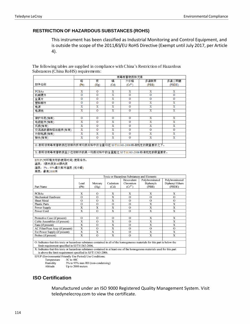
Teledyne LeCroy Environmental Compliance
114114
RESTRICTION OF HAZARDOUS SUBSTANCES (ROHS)
This instrument has been classified as Industrial Monitoring and Control Equipment, and is outside the scope of the 2011/65/EU RoHS Directive (Exempt until July 2017, per Article 4).
The fo llo wing tab les are supp lied in co mp liance with C hina’s Restriction o f Hazardo us
Substances (C hina RoHS) req uirements:
ISO Certification
Manufactured under an ISO 9000 Registered Quality Management System. Visit teledynelecroy.com to view the certificate.
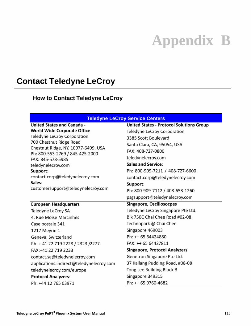
Appendix B
Teledyne LeCroy PeRT3 Phoenix System User Manual 115115
Teledyne LeCroy Service Centers
United States and Canada ‐ World Wide Corporate Office Teledyne LeCroy Corporation 700 Chestnut Ridge Road Chestnut Ridge, NY, 10977‐6499, USA Ph: 800‐553‐2769 / 845‐425‐2000 FAX: 845‐578‐5985 teledynelecroy.com Support: [email protected] Sales: [email protected]
United States ‐ Protocol Solutions Group
Teledyne LeCroy Corporation
3385 Scott Boulevard
Santa Clara, CA, 95054, USA
FAX: 408‐727‐0800
teledynelecroy.com
Sales and Service:
Ph: 800‐909‐7211 / 408‐727‐6600
Support:
Ph: 800‐909‐7112 / 408‐653‐1260
Singapore, Oscillosocpes
Teledyne LeCroy Singapore Pte Ltd.
Blk 750C Chai Chee Road #02‐08
Technopark @ Chai Chee
Singapore 469003
Ph: ++ 65 64424880
FAX: ++ 65 64427811
Singapore, Protocol Analyzers
Genetron Singapore Pte Ltd.
37 Kallang Pudding Road, #08‐08
Tong Lee Building Block B
Singapore 349315
Ph: ++ 65 9760‐4682
Contact Teledyne LeCroy
How to Contact Teledyne LeCroy
European Headquarters
Teledyne LeCroy SA
4, Rue Moïse Marcinhes
Case postale 341
1217 Meyrin 1
Geneva, Switzerland
Ph: + 41 22 719 2228 / 2323 /2277
FAX:+41 22 719 2233
teledynelecroy.com/europe
Protocol Analyzers:
Ph: +44 12 765 03971

Teledyne LeCroy How to Contact Teledyne LeCroy
Teledyne LeCroy Service Centers
China
Teledyne LeCroy Corporation Beijing
Rm. 2001 ‐ Office; Rm. 2002 ‐ Service Center
Unit A, Horizon Plaza
No. 6, Zhichun Road, Haidian District
Beijing 100088, China
Ph: ++86 10 8280 0318 / 0319 / 0320
FAX:++86 10 8280 0316
Service:
Rm. 2002
Ph: ++86 10 8280 0245
Korea
Teledyne LeCroy Korea
10th fl.Ildong Bldg.
968‐5 Daechi‐dong, Gangnam‐gu
Seoul 135‐280, Korea
Ph: ++ 82 2 3452 0400
FAX: ++ 82 2 3452 0490
Taiwan
LeColn Technology Co Ltd.
Far East Century Park, C3, 9F
No. 2, Chien‐8th Road,
Chung‐Ho Dist., New Taipei City, Taiwan
Ph: ++ 886 2 8226 1366
FAX: ++ 886 2 8226 1368
Japan
Teledyne LeCroy Japan
Hobunsya Funchu Bldg, 3F
3‐11‐5, Midori‐cho, Fuchu‐Shi
Tokyo 183‐0006, Japan
Ph: ++ 81 4 2402 9400
FAX: ++ 81 4 2402 9586
teledynelecroy.com/japan
116

Index
Teledyne LeCroy PeRT3 Phoenix System User Manual 117
Symbols .NET 3.5 installation 17
%Confidence 61
A AC Power 17
Adding data to patterns 91
Adjust RD‐ 87
Adjust RD+ 87
Allowable Patterns 71
Analysis tab 62, 93, 96
Annual calibration 13
Apply 50
Arbitrary Date 71
Auto display graph 63, 93
Auto reset on lost lock 79
Automatic range 54
Automation panel 79
B Back Panel Connections 16
Basic Data panel 77
BER threshold 100
Building a Test Script 78
C Cancel 50
CDB (H) field 91
Channel Master tab 52, 80
Channel Tab 52
Channel tab 52
Channels 63
Channels drop‐down menu 22
Clock Out 49, 50, 66, 78
Clock Out panel 66
color 110
Color theme 67, 110
Configuration panel 47, 49, 71, 107
Connect 47, 52
Connecting remotely 19
Copy 87
Count 51
CRC errors 12
CRC value 12, 90, 92
Create New Item 83
Creating a new test pattern 83
Creator 77
CSV file 98
Custom protocol 49
Custom Steps 55
Customize keyboard 106
Cut 87
D Data 101
Data outside of a frame 91
Data Set 100
Data Set panel 95, 99, 100, 101
Decode As 83
Decode Buttons 70, 104
Default Settings 83
Default Settings panel 63, 93
Delete 41
Delete Data 87
Delete Frame 87
Device Description panel 77
Diagnostics panel 66
Disconnect 47, 52
Display Mode panel 83, 85
DUT initialization 49
DUT Initialization panel 47, 83, 107
DUT is Device 77
DUT is Host 77
DUT Status panel 47, 52, 107
Teledyne LeCroy Index
118118
E Elapsed Time 61
Enable Range 54, 55
Errors vs. Time 99
Exact control of test ranges 54
Exit 45, 105
Export 41, 98
Export current database 44
Export Current Document 98, 103, 104
Export current document 44, 98
Export Result Database 105
Export result database 44
Export Test Database 105
Exporting files (scripts, patterns, test reports) 44
External Jitter panel 66
External OOB Board 64, 65
External Options panel 64
Eye diagram 34
Eye Diagram panel 80
Eye Preview panel 62
F File Menu 42
Filter 41
Filter button 71
Find BER Curve 61
Floating window 73, 108
Frame Level 79
G Generator Only 49
Graph Type panel 94, 96, 97, 98, 101
Graphs and reports 93
H Hardware configurations 12
Hardware upgrades 13
Hide Buttons 70, 104
High Frequency Random Jitter 59
High Frequency Sinusoidal Jitter panel 59
host machine 16, 39
host machine minimum requirements 16
Host/Device 63
I Import Data 91
Import from XML 104, 105
Import/Export panel 88, 91
Importing new files 43
Initialization command sequence 79
Initialization panel 79
Initialize 50
Insert Above 81
Insert Data 87, 91
Insert Frame 87, 89
Introduction of Distortion 34, 53
Introduction of Stress 34
J Jitter eye diagram 62
Jitter In connector 66
L Log View 97
LoopBack 79
Loopback 52, 79
Low Frequency Random Jitter 59
Low Frequency Sinusoidal Jitter panel 59
Low to High 54
M Magnification 96
Main 66
Main application window 20, 26, 39, 45, 47, 73, 74, 75, 76,
83, 103, 107
Main Library Toolbar 70
Main Library window 19, 25, 40, 41, 67, 69, 70, 73, 74, 77, 83,
85, 108
Main tab 21, 47, 71, 83, 107
Maintenance agreements 13
Manual Test 47, 53
Master Controls pane 94
Master Controls panel 24, 47, 53, 60, 94, 107
Master Controls tab 60
Master panel 85
Max Bit Count 60
Max GBits 60
Modifying a Test 26
Multi Single Parameter 101
N New Test Pattern 43, 103, 104
New Test Script 43, 103, 104
Notifications panel 88
O On‐screen Keypad 56
On‐screen LEDs 47
Options 104, 105
Options tab 56, 63, 83, 93, 109, 110
Other Channel 62
Output window 25, 40, 66, 67, 73, 74, 108
Teledyne LeCroy PeRT3 Phoenix System User Manual 119119
Index Teledyne LeCroy
P Pass/Fail BER 61
PASS/FAIL Confidence 61
Paste 87
Pattern 60, 63
Pattern Checking panel 63
Pattern Edit panel 87
Pattern Editor 50, 60, 83
Pattern Editor window 83
Pattern tab 63, 83, 84, 85
Pattern/Termination pane 60
Pattern/Termination panel 60
Pause 47, 53
PeRT3 client 19
PeRT3 Eagle front panel 23
PeRT3 panel 47
PeRT3 Selection panel 22, 48, 107
PeRT3 server 19
PeRT3 System Software 17
Predefined test patterns 83
Print command 45
Print Preview 45, 104, 105
Print Test Suite 105
Protocol 63
Protocol Specific filter 71
Protocol‐enabled 12
Protocol‐specific errors 12
Q Quick Access Toolbar 103, 104
Quick Print 45, 103, 104
R Receiver Test 77
Receiver Test block 80
Redo 87
Ref Clk in 65
Reference Clock 16, 17
Reference Clock In 65
Region Select 96
Rename 41
Rename the Selected Item 85
Reports 93
Reset 52
Reset on each test case 79
Reset/Initialize 78, 80
Run Forever 60, 62
Running a Test 24
S Save 41
Scatter Chart 101
Script Data block 76
Script Data tab 76
Script Name 77
Scroll Graph 96
Sequence 50, 79
Setup panel 78
Signal amplitude 57
Signal bias 57
Signal Generation 53
Signal generator 49
Signal impairment 80
Signal impairment controls 53
Signal panel 57
Signal Parameters panel 95
Single Parameter 100
SMA connectors 23
Small screens 74
Software test suites 12
Spread spectrum clocking 49, 50, 78
Spreadsheet View 98
Standard Edit panel 87
Start (don’t record) 24, 47, 48, 53
Start (record results) 24, 47, 48, 53
Starting a new test script 75
Stop 60
Style 110
Suspend 53, 60
System components 15
System Control Ribbon 40, 47, 52, 73, 83, 93, 107, 108
System control ribbon 73
T Terminate after 60
Test Case 78, 80, 95
Test Case field 95
Test Description panel 77
Test Development 73
Test Development section 40
Test Patterns 40, 69, 70
Test Patterns tab 83
Test Results 40, 69
Test Results library 25
Test Script Data Panel 80
Test Script window 73
Test Scripts 40, 69, 70, 73, 80
Test Scripts tab 25, 26, 75, 77
Test Type 77
Threshold 99, 100, 101
120
Teledyne LeCroy Index
Time or Max Errors 61
Time or PASS/FAIL 61
Tool Tips 103
Tools panel 96
U Undo 87
Update with the valid value 90
USB drivers 18
User‐defined patterns 49
V Vendor Specific Pattern 50
Vendor‐specific command 83
Victim/aggressor testing 62
View Info panel 88
View panel 56, 67, 109, 110
View/Edit 41
W Working on a smaller screen 74
Z Zoom In 96
Zoom Out 96