manual apicom392 teledyne
DESCRIPTION
APLICATIVO INTERFACE PARA ANALISADORES TELEDYNETRANSCRIPT
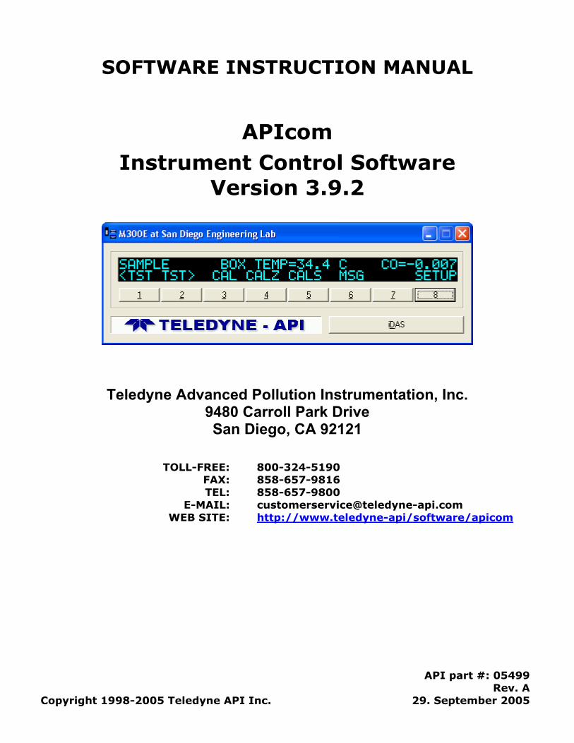
SOFTWARE INSTRUCTION MANUAL
APIcom Instrument Control Software
Version 3.9.2
Teledyne Advanced Pollution Instrumentation, Inc. 9480 Carroll Park Drive San Diego, CA 92121
TOLL-FREE: 800-324-5190 FAX: 858-657-9816 TEL: 858-657-9800
E-MAIL: [email protected] WEB SITE: http://www.teledyne-api/software/apicom
API part #: 05499 Rev. A
Copyright 1998-2005 Teledyne API Inc. 29. September 2005
END USER LICENSE AGREEMENT (EULA) End-User License Agreement For APIcom Graphical Interface Software This End-User License Agreement ("EULA") is a legal agreement between you ("the user") and Teledyne Advanced Pollution Instrumentation Inc. ("T-API"), San Diego, USA. The Software product (“APIcom”) includes computer software, the medias belonging to it, printed materials and electronic documentation. By installing, copying or any other usage of APIcom you agree to the terms of this agreement. If you do not agree to the terms of this EULA, do not install, copy, or use APIcom.
Software Product License APIcom is protected by US copyright laws and international copyright treaties, as well as other intellectual property laws and treaties. APIcom is licensed, not sold.
Grant Of License This EULA grants you the following non-exclusive rights:
You may install and use the enclosed APIcom on your computers to control API instruments, which were certified to work with APIcom or to test and evaluate the software itself.
You may not reverse-engineer, decompile, or disassemble APIcom, except and only to the extent that such activity is expressly permitted by applicable law notwithstanding this limitation.
You may not sell, rent or lease APIcom.
You may distribute APIcom free of charge to anyone, provided you distribute all applicable files and portions thereof in one package (manuals, release notes, supporting files).
Limitation Of Liability No liability for consequential damages. To the maximum extent permitted by applicable law, in no event shall API, USA or its suppliers be liable for any damages whatsoever (including, without limitation, damages for loss of business profit, business interruption, loss of business information, or any other pecuniary loss) arising out of the use of, or inability to use, this software product, even if API, USA has been advised of the possibility of such damages.
APIcom software and documentation - Copyright © 1998-2005 by Teledyne Advanced Pollution Instrumentation, Inc., San Diego, California, USA.
05499 Rev. A ii
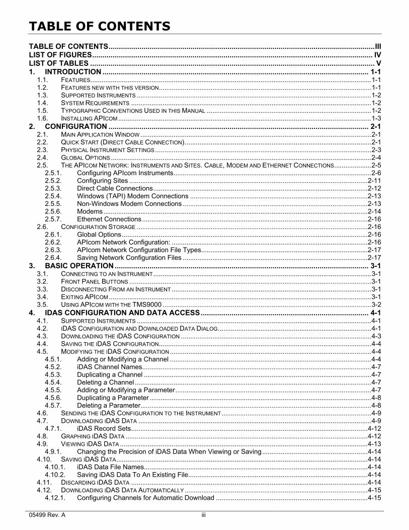
TABLE OF CONTENTS
TABLE OF CONTENTS..................................................................................................................................III LIST OF FIGURES......................................................................................................................................... IV LIST OF TABLES ........................................................................................................................................... V 1. INTRODUCTION .................................................................................................................................. 1-1
1.1. FEATURES........................................................................................................................................................1-1 1.2. FEATURES NEW WITH THIS VERSION...................................................................................................................1-1 1.3. SUPPORTED INSTRUMENTS ...............................................................................................................................1-2 1.4. SYSTEM REQUIREMENTS ..................................................................................................................................1-2 1.5. TYPOGRAPHIC CONVENTIONS USED IN THIS MANUAL .........................................................................................1-2 1.6. INSTALLING APICOM .........................................................................................................................................1-3
2. CONFIGURATION ............................................................................................................................... 2-1 2.1. MAIN APPLICATION WINDOW .............................................................................................................................2-1 2.2. QUICK START (DIRECT CABLE CONNECTION).....................................................................................................2-1 2.3. PHYSICAL INSTRUMENT SETTINGS.....................................................................................................................2-3 2.4. GLOBAL OPTIONS.............................................................................................................................................2-4 2.5. THE APICOM NETWORK: INSTRUMENTS AND SITES. CABLE, MODEM AND ETHERNET CONNECTIONS....................2-5
2.5.1. Configuring APIcom Instruments...........................................................................................................2-6 2.5.2. Configuring Sites .................................................................................................................................2-11 2.5.3. Direct Cable Connections....................................................................................................................2-12 2.5.4. Windows (TAPI) Modem Connections ................................................................................................2-13 2.5.5. Non-Windows Modem Connections ....................................................................................................2-13 2.5.6. Modems...............................................................................................................................................2-14 2.5.7. Ethernet Connections..........................................................................................................................2-16
2.6. CONFIGURATION STORAGE .............................................................................................................................2-16 2.6.1. Global Options.....................................................................................................................................2-16 2.6.2. APIcom Network Configuration: ..........................................................................................................2-16 2.6.3. APIcom Network Configuration File Types..........................................................................................2-17 2.6.4. Saving Network Configuration Files ....................................................................................................2-17
3. BASIC OPERATION ............................................................................................................................ 3-1 3.1. CONNECTING TO AN INSTRUMENT......................................................................................................................3-1 3.2. FRONT PANEL BUTTONS ...................................................................................................................................3-1 3.3. DISCONNECTING FROM AN INSTRUMENT ............................................................................................................3-1 3.4. EXITING APICOM ..............................................................................................................................................3-1 3.5. USING APICOM WITH THE TMS9000 .................................................................................................................3-2
4. IDAS CONFIGURATION AND DATA ACCESS.................................................................................. 4-1 4.1. SUPPORTED INSTRUMENTS ...............................................................................................................................4-1 4.2. IDAS CONFIGURATION AND DOWNLOADED DATA DIALOG...................................................................................4-1 4.3. DOWNLOADING THE IDAS CONFIGURATION .......................................................................................................4-3 4.4. SAVING THE IDAS CONFIGURATION...................................................................................................................4-4 4.5. MODIFYING THE IDAS CONFIGURATION.............................................................................................................4-4
4.5.1. Adding or Modifying a Channel .............................................................................................................4-4 4.5.2. iDAS Channel Names............................................................................................................................4-7 4.5.3. Duplicating a Channel ...........................................................................................................................4-7 4.5.4. Deleting a Channel ................................................................................................................................4-7 4.5.5. Adding or Modifying a Parameter..........................................................................................................4-7 4.5.6. Duplicating a Parameter........................................................................................................................4-8 4.5.7. Deleting a Parameter.............................................................................................................................4-8
4.6. SENDING THE IDAS CONFIGURATION TO THE INSTRUMENT.................................................................................4-9 4.7. DOWNLOADING IDAS DATA ..............................................................................................................................4-9
4.7.1. iDAS Record Sets................................................................................................................................4-12 4.8. GRAPHING IDAS DATA ...................................................................................................................................4-12 4.9. VIEWING IDAS DATA ......................................................................................................................................4-13
4.9.1. Changing the Precision of iDAS Data When Viewing or Saving.........................................................4-14 4.10. SAVING IDAS DATA........................................................................................................................................4-14
4.10.1. iDAS Data File Names.........................................................................................................................4-14 4.10.2. Saving iDAS Data To An Existing File.................................................................................................4-14
4.11. DISCARDING IDAS DATA ................................................................................................................................4-14 4.12. DOWNLOADING IDAS DATA AUTOMATICALLY ...................................................................................................4-15
4.12.1. Configuring Channels for Automatic Download ..................................................................................4-15 05499 Rev. A iii
4.12.2. Selecting Channels for Automatic Download ......................................................................................4-15 4.12.3. Activating Automatic Download Mode.................................................................................................4-15 4.12.4. File Names For Automatic Download..................................................................................................4-15
5. M700 CALIBRATOR SEQUENCES .................................................................................................... 5-1 5.1. SEQUENCE CONFIGURATION DIALOG.................................................................................................................5-1 5.2. DOWNLOADING A SEQUENCE CONFIGURATION...................................................................................................5-2 5.3. SAVING A SEQUENCE CONFIGURATION ..............................................................................................................5-2 5.4. MODIFYING A SEQUENCE CONFIGURATION.........................................................................................................5-3
5.4.1. Adding or Modifying a Sequence ..........................................................................................................5-3 5.4.2. Sequence Names..................................................................................................................................5-5 5.4.3. Duplicating a Sequence ........................................................................................................................5-5 5.4.4. Moving a Sequence...............................................................................................................................5-5 5.4.5. Deleting a Sequence .............................................................................................................................5-5 5.4.6. Adding Steps to a Sequence.................................................................................................................5-5 5.4.7. Generate Step .......................................................................................................................................5-7 5.4.8. GPT and GPT Preset Steps ..................................................................................................................5-7 5.4.9. Manual Steps.........................................................................................................................................5-8 5.4.10. Duration Steps.......................................................................................................................................5-8 5.4.11. Execute Sequence Steps ......................................................................................................................5-9 5.4.12. Select Output Steps...............................................................................................................................5-9 5.4.13. Select Output Steps...............................................................................................................................5-9 5.4.14. Duplicating a Step ...............................................................................................................................5-10 5.4.15. Moving a Step......................................................................................................................................5-10 5.4.16. Deleting a Step ....................................................................................................................................5-10
5.5. SENDING THE SEQUENCE CONFIGURATION TO THE INSTRUMENT.......................................................................5-10 6. ADVANCED FEATURES..................................................................................................................... 6-1
6.1. INSTRUMENT INFORMATION DIALOG...................................................................................................................6-1 6.2. COMMUNICATION LOGGING ...............................................................................................................................6-3
APPENDIX A. FIRMWARE COMPATIBILITY .............................................................................A-1 A.1. REMOTE (RS-232) CONFIGURATION OF IDAS .................................................................................................. A-1 A.2. NUMBER OF SAMPLES IN CONCENTRATION AVERAGE ........................................................................................ A-2
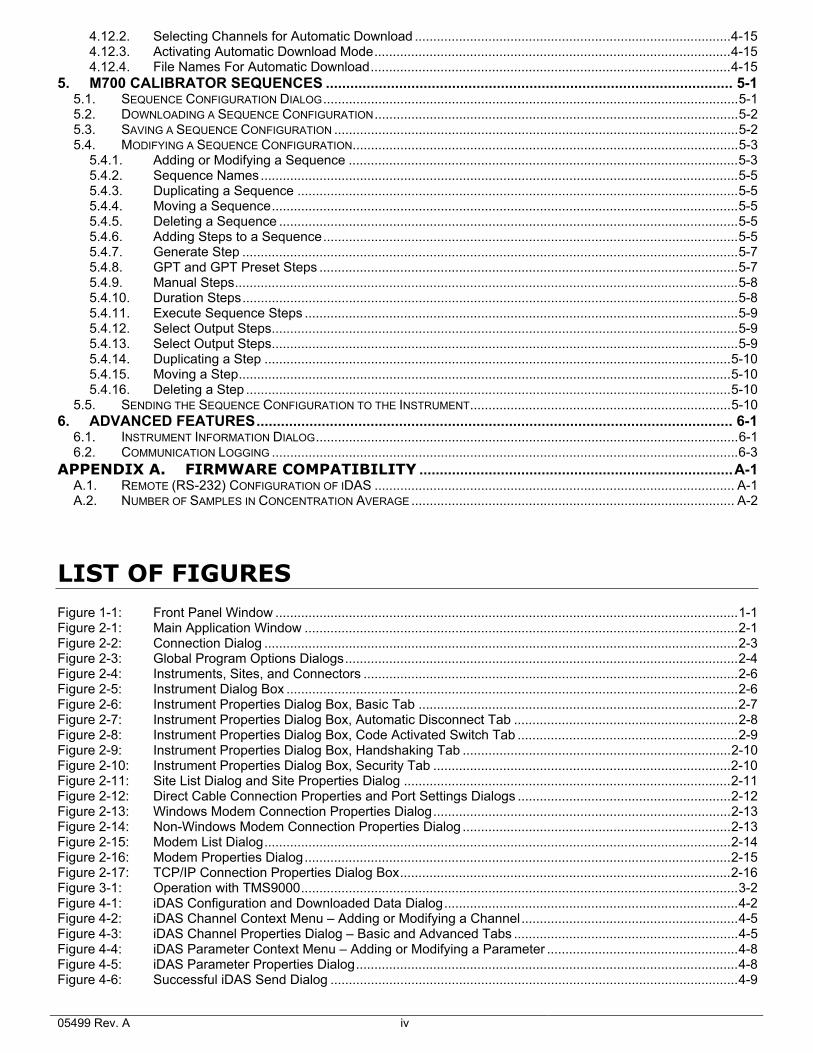
LIST OF FIGURES Figure 1-1: Front Panel Window ..............................................................................................................................1-1 Figure 2-1: Main Application Window ......................................................................................................................2-1 Figure 2-2: Connection Dialog .................................................................................................................................2-3 Figure 2-3: Global Program Options Dialogs...........................................................................................................2-4 Figure 2-4: Instruments, Sites, and Connectors ......................................................................................................2-6 Figure 2-5: Instrument Dialog Box ...........................................................................................................................2-6 Figure 2-6: Instrument Properties Dialog Box, Basic Tab .......................................................................................2-7 Figure 2-7: Instrument Properties Dialog Box, Automatic Disconnect Tab .............................................................2-8 Figure 2-8: Instrument Properties Dialog Box, Code Activated Switch Tab ............................................................2-9 Figure 2-9: Instrument Properties Dialog Box, Handshaking Tab .........................................................................2-10 Figure 2-10: Instrument Properties Dialog Box, Security Tab .................................................................................2-10 Figure 2-11: Site List Dialog and Site Properties Dialog .........................................................................................2-11 Figure 2-12: Direct Cable Connection Properties and Port Settings Dialogs ..........................................................2-12 Figure 2-13: Windows Modem Connection Properties Dialog.................................................................................2-13 Figure 2-14: Non-Windows Modem Connection Properties Dialog .........................................................................2-13 Figure 2-15: Modem List Dialog...............................................................................................................................2-14 Figure 2-16: Modem Properties Dialog....................................................................................................................2-15 Figure 2-17: TCP/IP Connection Properties Dialog Box..........................................................................................2-16 Figure 3-1: Operation with TMS9000.......................................................................................................................3-2 Figure 4-1: iDAS Configuration and Downloaded Data Dialog................................................................................4-2 Figure 4-2: iDAS Channel Context Menu – Adding or Modifying a Channel...........................................................4-5 Figure 4-3: iDAS Channel Properties Dialog – Basic and Advanced Tabs .............................................................4-5 Figure 4-4: iDAS Parameter Context Menu – Adding or Modifying a Parameter ....................................................4-8 Figure 4-5: iDAS Parameter Properties Dialog........................................................................................................4-8 Figure 4-6: Successful iDAS Send Dialog ...............................................................................................................4-9
05499 Rev. A iv
Figure 4-7: Unsuccessful iDAS Send Dialog ...........................................................................................................4-9 Figure 4-8: Select Records Dialog.........................................................................................................................4-10 Figure 4-9: Downloading iDAS Data....................................................................................................................4-11 Figure 4-10: Downloaded iDAS Data.......................................................................................................................4-12 Figure 4-11: Graphing Multiple iDAS Parameters With Different Scales.................................................................4-13 Figure 4-12: Viewing iDAS Data ..............................................................................................................................4-13 Figure 4-13: Saved iDAS Data.................................................................................................................................4-14 Figure 5-1: Sequence Configuration Dialog.............................................................................................................5-1 Figure 5-2: Sequence Context Menu – Adding or Modifying a Sequence ..............................................................5-3 Figure 5-3: Sequence Properties Dialog..................................................................................................................5-4 Figure 5-4: Invalid Sequence Name Dialog .............................................................................................................5-5 Figure 5-5: Delete Sequence Confirmation Dialog ..................................................................................................5-5 Figure 5-6: Select Step Type Dialog........................................................................................................................5-6 Figure 5-7: Sequence Step Context Menu ..............................................................................................................5-6 Figure 5-8: Generate Step Properties Dialog ..........................................................................................................5-7 Figure 5-9: GPT Step Properties Dialog ..................................................................................................................5-7 Figure 5-10: GPT Preset Step Properties Dialog.......................................................................................................5-7 Figure 5-11: Manual Step Properties Dialog..............................................................................................................5-8 Figure 5-12: Duration Step Properties Dialog............................................................................................................5-8 Figure 5-13: Execute Sequence Step Properties Dialog ...........................................................................................5-9 Figure 5-14: Select Output Step Properties Dialog....................................................................................................5-9 Figure 5-15: Set CC Output Step Properties Dialog................................................................................................5-10 Figure 5-16: Delete Step Confirmation Dialog .........................................................................................................5-10 Figure 5-17: Sequence Send Configuration Confirmation Dialog............................................................................5-11 Figure 5-18: Successful Sequence Send Dialog .....................................................................................................5-11 Figure 5-19: Unsuccessful Sequence Send Dialog .................................................................................................5-11 Figure 6-1: Instrument Information Dialog ...............................................................................................................6-1 Figure 6-2: Sample Log File.....................................................................................................................................6-3
LIST OF TABLES Table 2-1: Main Application Window Toolbar Buttons ................................................................................................2-1 Table 2-2: Global Options ...........................................................................................................................................2-4 Table 2-3: Instrument Properties, Basic Tab ..............................................................................................................2-7 Table 2-4: Instrument Properties, Automatic Disconnect Tab ....................................................................................2-8 Table 2-5: Instrument Properties, Code Activated Switch Tab ...................................................................................2-9 Table 2-6: Instrument Properties, Handshaking Tab ................................................................................................2-10 Table 2-7: Instrument Properties, Security Tab ........................................................................................................2-11 Table 2-8: Site Properties .........................................................................................................................................2-12 Table 2-9: Windows Modem Connection Properties ................................................................................................2-13 Table 2-10: Non-Windows Modem Connection Properties ....................................................................................2-14 Table 2-11: Modem Properties ...............................................................................................................................2-15 Table 4-1: Instruments Containing iDAS.....................................................................................................................4-1 Table 4-2: iDAS Configuration and Downloaded Data Dialog Buttons.......................................................................4-2 Table 4-3: iDAS Channel Properties...........................................................................................................................4-5 Table 4-4: iDAS Parameter Properties .......................................................................................................................4-8 Table 4-5: Select Records Dialog .............................................................................................................................4-10 Table 5-1: Sequence Configuration Dialog Buttons....................................................................................................5-1 Table 5-2: Sequence Properties .................................................................................................................................5-4 Table 5-3: Sequence Step Types ...............................................................................................................................5-5 Table 5-4: Generate Step Properties ..........................................................................................................................5-7 Table 5-5: GPT and GPT Preset Step Properties.......................................................................................................5-8 Table 5-6: Manual Step Properties .............................................................................................................................5-8 Table 5-7: Duration Step Properties ...........................................................................................................................5-9 Table 5-8: Execute Sequence Step Properties...........................................................................................................5-9 Table 5-9: Select Output Step Properties ...................................................................................................................5-9 Table 5-10: Set CC Output Step Properties ...........................................................................................................5-10 Table 6-1: Instrument Information Dialog....................................................................................................................6-1 Table 6-2: Log Entry Classification Codes..................................................................................................................6-3 Table 6-3: Instruments Supporting iDAS Configuration Through RS-232 ................................................................. A-1 Table 6-4: Models Supporting "Number of samples" in iDAS channels & "Use internal clock" in iDAS download ... A-2
05499 Rev. A v

1. INTRODUCTION
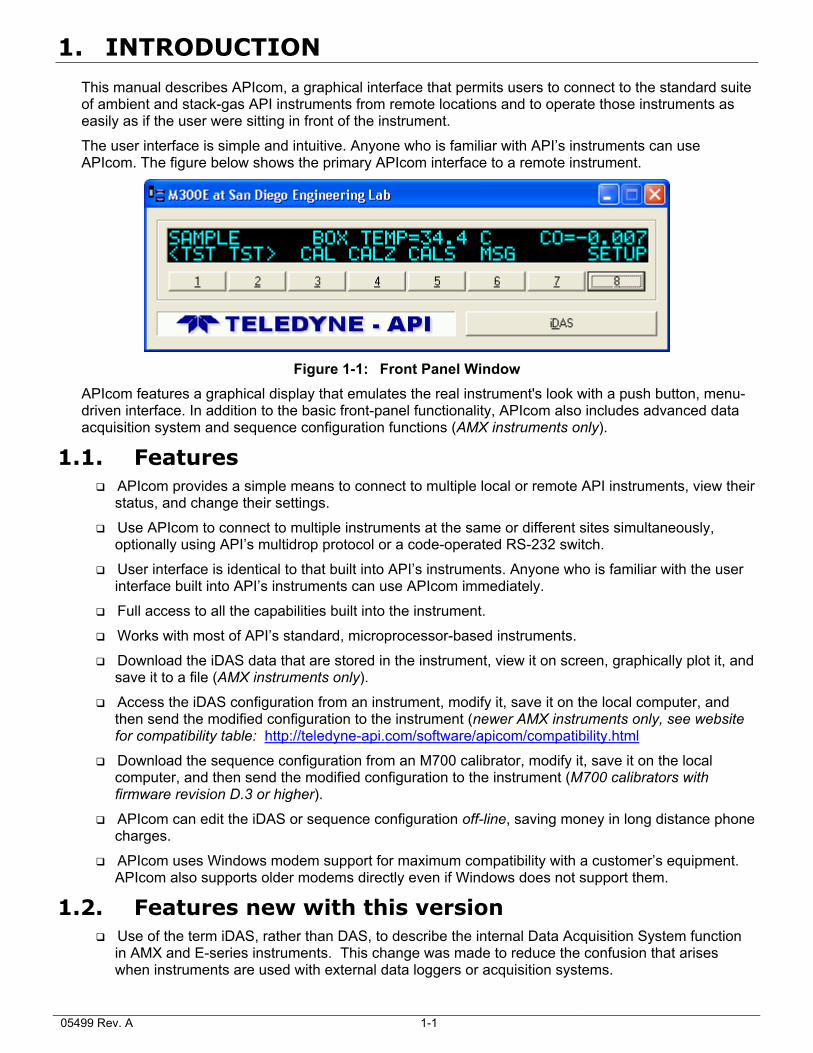
This manual describes APIcom, a graphical interface that permits users to connect to the standard suite of ambient and stack-gas API instruments from remote locations and to operate those instruments as easily as if the user were sitting in front of the instrument.
The user interface is simple and intuitive. Anyone who is familiar with API’s instruments can use APIcom. The figure below shows the primary APIcom interface to a remote instrument.
Figure 1-1: Front Panel Window
APIcom features a graphical display that emulates the real instrument's look with a push button, menu-driven interface. In addition to the basic front-panel functionality, APIcom also includes advanced data acquisition system and sequence configuration functions (AMX instruments only).
1.1. Features APIcom provides a simple means to connect to multiple local or remote API instruments, view their
status, and change their settings.
Use APIcom to connect to multiple instruments at the same or different sites simultaneously, optionally using API’s multidrop protocol or a code-operated RS-232 switch.
User interface is identical to that built into API’s instruments. Anyone who is familiar with the user interface built into API’s instruments can use APIcom immediately.
Full access to all the capabilities built into the instrument. Works with most of API’s standard, microprocessor-based instruments.
Download the iDAS data that are stored in the instrument, view it on screen, graphically plot it, and save it to a file (AMX instruments only).
Access the iDAS configuration from an instrument, modify it, save it on the local computer, and then send the modified configuration to the instrument (newer AMX instruments only, see website for compatibility table: http://teledyne-api.com/software/apicom/compatibility.html
Download the sequence configuration from an M700 calibrator, modify it, save it on the local computer, and then send the modified configuration to the instrument (M700 calibrators with firmware revision D.3 or higher).
APIcom can edit the iDAS or sequence configuration off-line, saving money in long distance phone charges.
APIcom uses Windows modem support for maximum compatibility with a customer’s equipment. APIcom also supports older modems directly even if Windows does not support them.
1.2. Features new with this version Use of the term iDAS, rather than DAS, to describe the internal Data Acquisition System function
in AMX and E-series instruments. This change was made to reduce the confusion that arises when instruments are used with external data loggers or acquisition systems.
05499 Rev. A 1-1
APIcom Instruction Manual Introduction
05499 Rev. A 1-2
Supports the new iDAS SDEV sampling mode.
Lengthy data downloads from the iDAS can now be aborted using a “Cancel” button to the iDAS dialog to abort lengthy data downloads.
APIcom now supports “total flow rate” specification for the M700 (M700 software revisions F.3 and later), as well as Generate, GPT, and GPT-preset steps.
Support for the TMS Terminus and TMS modules via the terminus, but not standalone TMS modules.
The Instrument Information dialog (see section 6.1) has been enhanced to show the instrument’s software part number, whether the instrument’s iDAS has the new SDEV mode, and whether the target instrument supports the “Download Cancel” feature.
The default file type when saving data downloaded from the iDAS has been changed to “.CSV”. This was done to better support users that analyze data with Excel.
Online help is now a Portable Document File (.pdf) that can also be used for printing the manual.
1.3. Supported Instruments Since APIcom uses standard commands that are built into all API instruments, it will work with all API microprocessor-based instruments. However, APIcom works much better with AMX instruments and all E-series instruments because of the higher baud rates supported by these models.
When connecting to older instruments operating at 2400 baud, it takes nearly one second for APIcom to transmit a button press and receive the display contents. When connecting to AMX instruments operating at 19,200 baud, the same action will appear instantaneously.
Some of the iDAS functionality is supported only by newer revisions of firmware. Please refer to the tables in Appendix A to find out if your instrument’s firmware revision is supported. Consult our sales department or the APIcom website to find out if and how it can be upgraded to support that functionality:
http://teledyne-api.com/software/apicom/compatibility.html
The basic front-panel functionality is supported by all our analyzers.
1.4. System Requirements APIcom runs only on 32-bit Windows operating systems (Windows 95/98/ME/NT/2000/XP). Do not attempt to run the program on Windows 3.1.
APIcom requires 4–20 MB of RAM during normal operation, 5 MB of disk space for installation, and more disk space for storing iDAS data and scripts.
Some versions of Windows 95 and NT4 may not have the correct common user interface dynamic link libraries that APIcom requires in order to display checkboxes in the iDAS configuration tree. These checkboxes make it convenient to select iDAS channels and parameters to download iDAS data from. See Section 4.6 for a work-around solution.
The problem can be corrected by installing Microsoft Internet Explorer 5.0 or higher. Please point your internet browser to this location to see the latest updates: http://windowsupdate.microsoft.com/
1.5. Typographic Conventions Used in this Manual All of the examples used in this manual refer to specific instruments and sites. Keep in mind that names of instruments and sites will be different from those of the user.
In this manual, names of push buttons on the actual instrument front panel are indicated using bold capital characters, for example, SETUP. Push button sequences are denoted by a series of button names, separated by dashes, such as SETUP-MORE-COMM-BAUD.
APIcom menus are depicted in bold, as in File-New. Buttons in dialog boxes and on the toolbar are
shown as bitmap images, like this: .
APIcom Instruction Manual Introduction
05499 Rev. A 1-3
Names of items such as files and setup variables are indicated using italicized capital characters, as in RS232_MODE.
1.6. Installing APIcom If the installation file was downloaded, simply locate the file named APIcom.Installer.X.X.exe on the hard drive and double-click on it, then follow the instructions. (X.X being the revision number).
If APIcom was received on CD, locate your CD drive in Explorer, locate the file named APIcom.Installer.X.X.exe and double-click on it, then follow the instructions. (X.X being the revision number).
The APIcom installer is a stand-alone, executable installation routine, which copies the following files to the hard drive into a user-selected directory/folder:
APIcom.exe - the program
README.txt - a readme file with late-breaking news and latest changes to the program. You will have a chance to read this file during installation.
APIcom.license.agreement.txt - the software license agreement to which you have to agree upon installation of APIcom. You will have a chance to read this file during installation.
APIcom_User_Manual.pdf - User manual in Acrobat PDF format for printing purposes and for online help. This file MUST be located in the same directory as APIcom.
For advanced users: Upon installation, APIcom creates the following registry entries. These entries - including all previously stored program and window settings - are completely removed when uninstalling APIcom. Note that network configuration files (site, instrument and iDAS settings) are not affected by uninstalling APIcom.
HKEY_CURRENT_USER\Software\Advanced Pollution Instrumentation\APIcom
DAS Settings
Recent File List
Settings
NOTE If there already is a previous version of APIcom installed, the installation utility will prompt to replace the previous version. However, the previous version can be "upgraded" to the latest version by selecting "NO" when prompted to uninstall. This will leave the existing program settings (window locations, last used configuration files etc.) intact and only over-write any existing files listed above. This is recommended for upgrades of version 3.0 and above.
CAUTION
Site and instrument definitions created with older versions of APIcom are stored in the network configuration files (.cfg). These files may not be compatible with the latest version of APIcom. When upgrading from version 1.17 to APIcom 3+, these sites and instruments may need to be re-defined. In this case, we recommend to select "YES" from the uninstall prompt and then choose a different directory to install APIcom 3.5. This will still leave the old 1.17 installation intact but will reset the program configuration settings. Note that old and new versions will share the same registry entries and, for example, a change in windows locations in version 3.5 will also be used for version 1.17. This makes it easy to maintain identical program settings for both versions.
For safety, we recommend to make a backup of all configuration and script files before installing or upgrading APIcom. We cannot take any responsibility for lost files, time or revenue due to lost or altered configuration settings and files.
The APIcom installer is virus-checked and safe to run. Never accept installation files from third parties (including your API distributor or representative), always download your own copy and do not trust that
APIcom Instruction Manual Introduction
05499 Rev. A 1-4
executables sent to you from anybody outside of API are safe to run. If in doubt, run a virus checker before and after running the installer file.
Uninstalling APIcom versions 3 and higher with the provided uninstallation utility (to be found in the APIcom program group) or when running the Installer again and selecting YES to uninstall previous versions, will delete all of the registry entries (program and iDAS settings) and the entire folder with APIcom files. The installer will not delete the folder if files were added by the user (e.g., network configuration files, iDAS scripts etc.). In this case, only the originally installed files will be removed. Likewise, if the program group folder is open in Explorer during the uninstallation, it will not be removed, only its shortcuts. Registry entries created by APIcom versions lower than 3 may not be removed properly upon installing version 3 and higher but this should not cause any problems.
2. CONFIGURATION
This section explains how to configure APIcom to connect to an instrument.
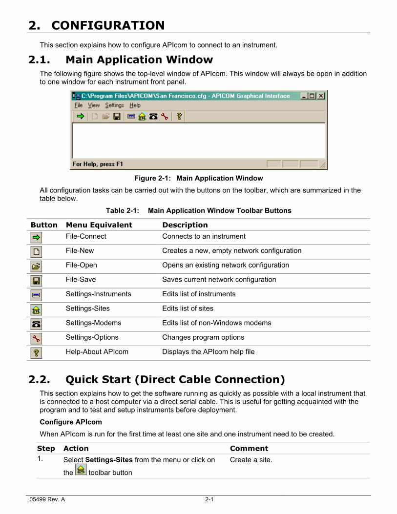
2.1. Main Application Window The following figure shows the top-level window of APIcom. This window will always be open in addition to one window for each instrument front panel.
Figure 2-1: Main Application Window
All configuration tasks can be carried out with the buttons on the toolbar, which are summarized in the table below.
Table 2-1: Main Application Window Toolbar Buttons
Button Menu Equivalent Description
File-Connect Connects to an instrument
File-New Creates a new, empty network configuration
File-Open Opens an existing network configuration
File-Save Saves current network configuration
Settings-Instruments Edits list of instruments
Settings-Sites Edits list of sites
Settings-Modems Edits list of non-Windows modems
Settings-Options Changes program options
Help-About APIcom Displays the APIcom help file
2.2. Quick Start (Direct Cable Connection) This section explains how to get the software running as quickly as possible with a local instrument that is connected to a host computer via a direct serial cable. This is useful for getting acquainted with the program and to test and setup instruments before deployment.
Configure APIcom When APIcom is run for the first time at least one site and one instrument need to be created.
Step Action Comment 1. Select Settings-Sites from the menu or click on
the toolbar button
Create a site.
05499 Rev. A 2-1
APIcom Instruction Manual Configuration
Step Action Comment
2. Click on to create a new site
3. Specify the site’s properties. 4.
Click to finish
5. Select Settings-Instruments from the menu or
click on the toolbar button
Create an instrument.
6. Click on to create a new instrument and specify the instrument’s properties
7. Click to finish
8. Attach a serial cable Refer to the following paragraph. Attach a serial cable from the computer’s COM (Serial) port that was specified in the site configuration to the RS-232 port of the instrument. The cable must be a “straight-through” cable with a DB-9, female plug on the instrument’s site and either a DB-9 or DB-25, female plug at the computer’s side. Please refer to the computer’s user manual on how to use the Serial port. Make sure that the plugs are securely fastened to ensure proper connection.
9. Configure the COM port Refer to the following paragraphs. From the Windows START menu, select Settings-Control Panels-Ports and make sure that the computer’s COM/Serial port is configured to the same baud rate as specified in the Instrument settings above. The COM settings must be as follows:
BAUD rate: up to 19200 kbaud, we recommend 9600. Longer cables may require lower baud rates. E-series instruments support up to 115 kbaud.
Data bits: 8
Parity: None
Stop bits: 1
Flow control: None
Optionally, newer instruments support Xon/Xoff flow control, which must be enabled in both the instrument and APIcom and must also be available for all instruments within one multi-drop chain.
Once all settings are configured, perform the remaining steps to connect to the instrument.
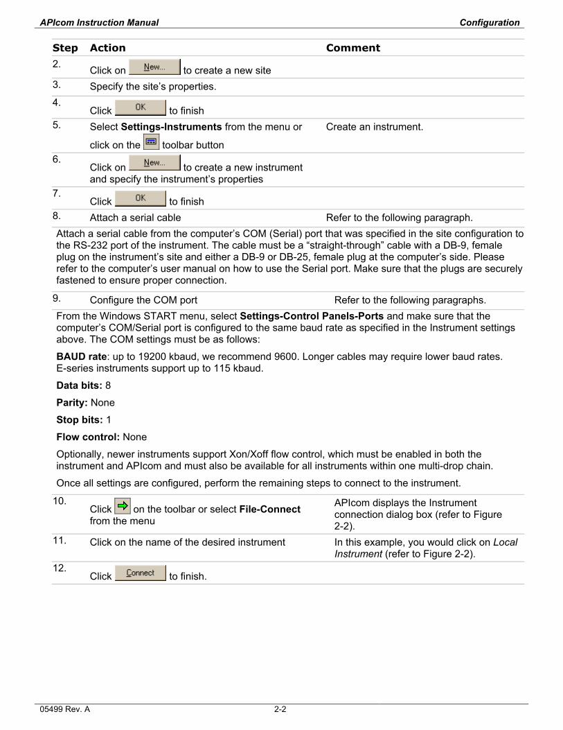
10. Click on the toolbar or select File-Connect from the menu
APIcom displays the Instrument connection dialog box (refer to Figure 2-2).
11. Click on the name of the desired instrument In this example, you would click on Local Instrument (refer to Figure 2-2).
12. Click to finish.
05499 Rev. A 2-2
APIcom Instruction Manual Configuration
Figure 2-2: Connection Dialog
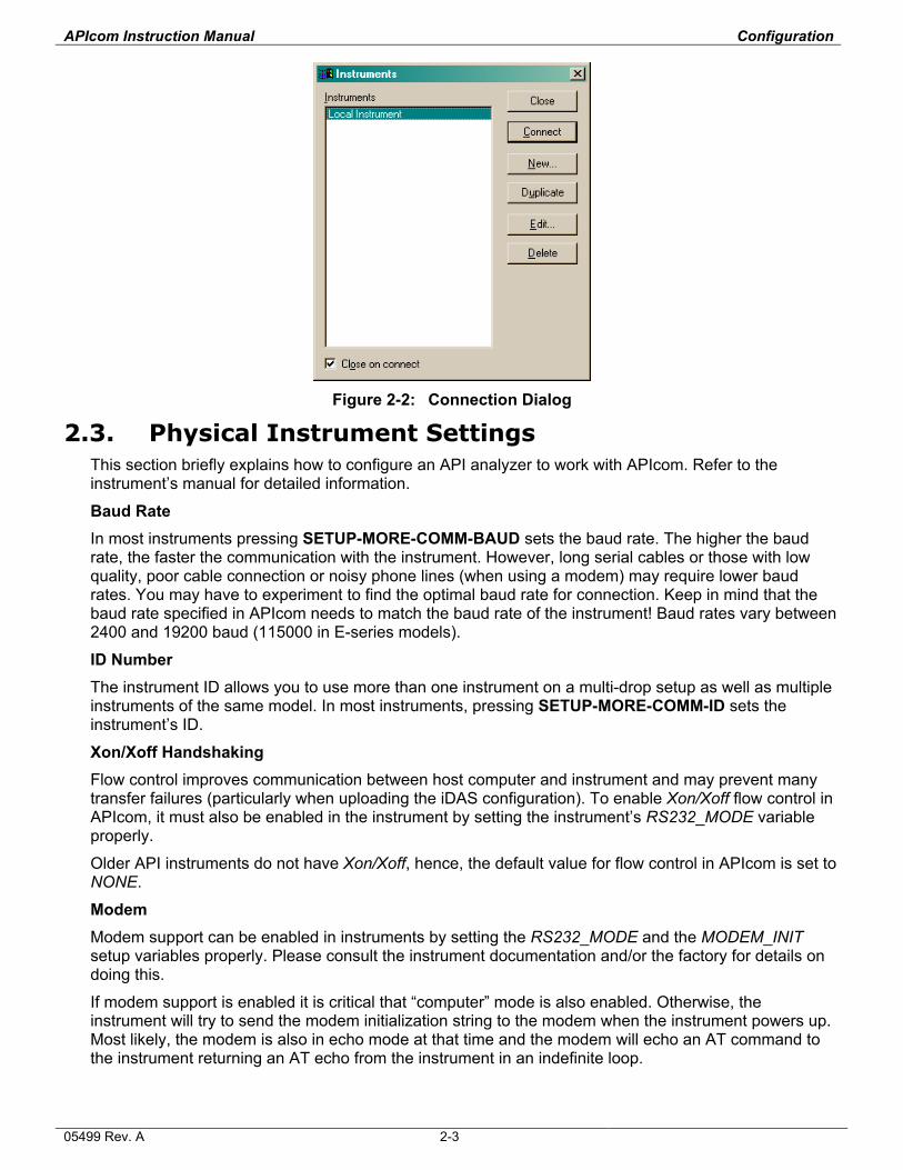
2.3. Physical Instrument Settings This section briefly explains how to configure an API analyzer to work with APIcom. Refer to the instrument’s manual for detailed information.
Baud Rate In most instruments pressing SETUP-MORE-COMM-BAUD sets the baud rate. The higher the baud rate, the faster the communication with the instrument. However, long serial cables or those with low quality, poor cable connection or noisy phone lines (when using a modem) may require lower baud rates. You may have to experiment to find the optimal baud rate for connection. Keep in mind that the baud rate specified in APIcom needs to match the baud rate of the instrument! Baud rates vary between 2400 and 19200 baud (115000 in E-series models).
ID Number The instrument ID allows you to use more than one instrument on a multi-drop setup as well as multiple instruments of the same model. In most instruments, pressing SETUP-MORE-COMM-ID sets the instrument’s ID.
Xon/Xoff Handshaking Flow control improves communication between host computer and instrument and may prevent many transfer failures (particularly when uploading the iDAS configuration). To enable Xon/Xoff flow control in APIcom, it must also be enabled in the instrument by setting the instrument’s RS232_MODE variable properly.
Older API instruments do not have Xon/Xoff, hence, the default value for flow control in APIcom is set to NONE.
Modem Modem support can be enabled in instruments by setting the RS232_MODE and the MODEM_INIT setup variables properly. Please consult the instrument documentation and/or the factory for details on doing this.
If modem support is enabled it is critical that “computer” mode is also enabled. Otherwise, the instrument will try to send the modem initialization string to the modem when the instrument powers up. Most likely, the modem is also in echo mode at that time and the modem will echo an AT command to the instrument returning an AT echo from the instrument in an indefinite loop.
05499 Rev. A 2-3
APIcom Instruction Manual Configuration
In addition, most of API’s instruments have a password protection capability in which the instrument will only accept commands after a password has been submitted. This security feature must be used carefully with modems. The problem is that while the modem is answering an incoming call, it sends status messages such as “RING” and “CONNECT” to the instrument, to which the instrument responds “MUST LOG ON” if the security mode is enabled. These messages sent by the instrument may cause some modems to hang up during the call. So the modem must be configured, using the MODEM_INIT setup variable, to not issue responses to the instrument if the security feature is used. This is accomplished in some modems with the AT command “Q1”.
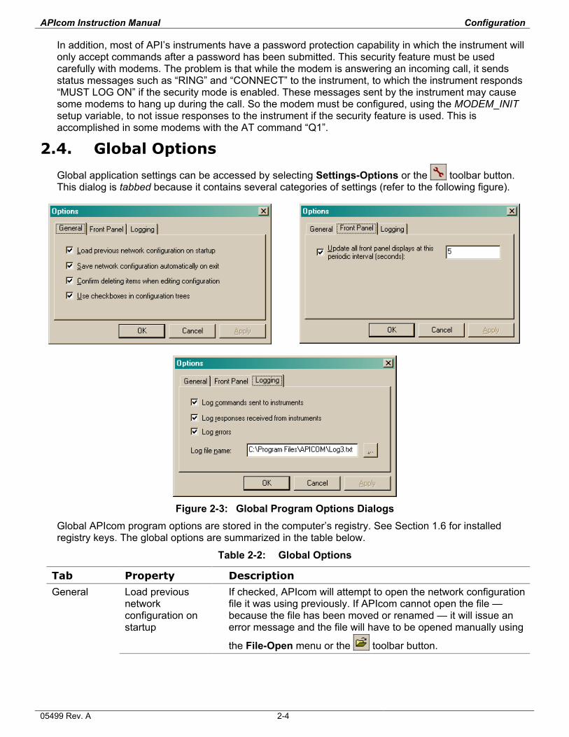
2.4. Global Options
Global application settings can be accessed by selecting Settings-Options or the toolbar button. This dialog is tabbed because it contains several categories of settings (refer to the following figure).
Figure 2-3: Global Program Options Dialogs
Global APIcom program options are stored in the computer’s registry. See Section 1.6 for installed registry keys. The global options are summarized in the table below.
Table 2-2: Global Options
Tab Property Description
General Load previous network configuration on startup
If checked, APIcom will attempt to open the network configuration file it was using previously. If APIcom cannot open the file —because the file has been moved or renamed — it will issue an error message and the file will have to be opened manually using
the File-Open menu or the toolbar button.
05499 Rev. A 2-4
APIcom Instruction Manual Configuration
Tab Property Description
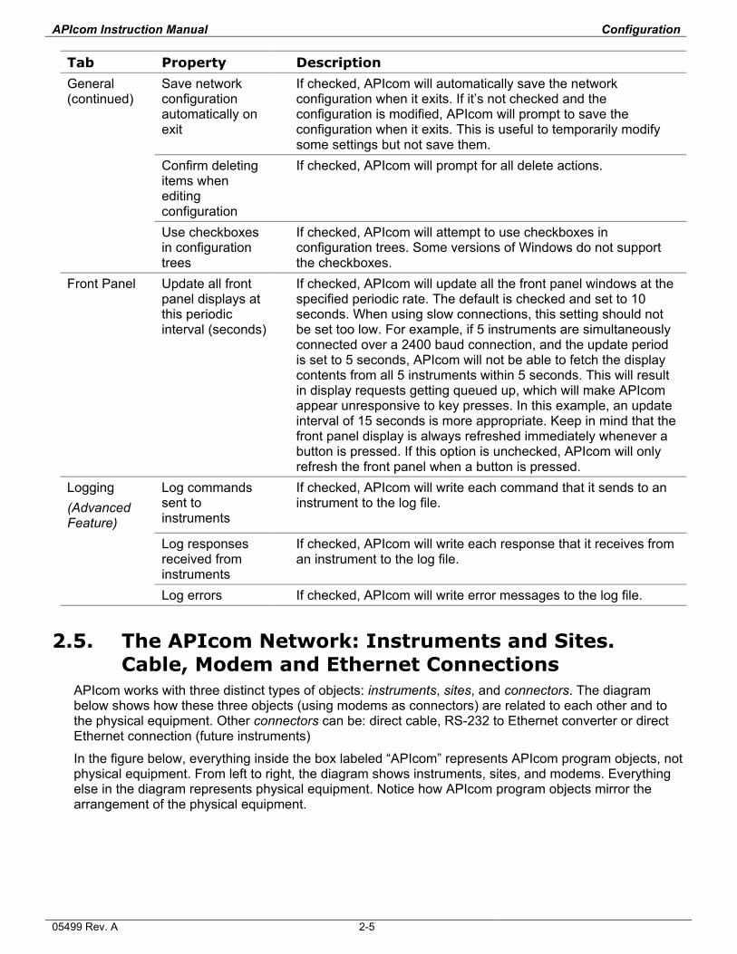
General (continued)
Save network configuration automatically on exit
If checked, APIcom will automatically save the network configuration when it exits. If it’s not checked and the configuration is modified, APIcom will prompt to save the configuration when it exits. This is useful to temporarily modify some settings but not save them.
Confirm deleting items when editing configuration
If checked, APIcom will prompt for all delete actions.
Use checkboxes in configuration trees
If checked, APIcom will attempt to use checkboxes in configuration trees. Some versions of Windows do not support the checkboxes.
Front Panel Update all front panel displays at this periodic interval (seconds)
If checked, APIcom will update all the front panel windows at the specified periodic rate. The default is checked and set to 10 seconds. When using slow connections, this setting should not be set too low. For example, if 5 instruments are simultaneously connected over a 2400 baud connection, and the update period is set to 5 seconds, APIcom will not be able to fetch the display contents from all 5 instruments within 5 seconds. This will result in display requests getting queued up, which will make APIcom appear unresponsive to key presses. In this example, an update interval of 15 seconds is more appropriate. Keep in mind that the front panel display is always refreshed immediately whenever a button is pressed. If this option is unchecked, APIcom will only refresh the front panel when a button is pressed.
Logging (Advanced Feature)
Log commands sent to instruments
If checked, APIcom will write each command that it sends to an instrument to the log file.
Log responses received from instruments
If checked, APIcom will write each response that it receives from an instrument to the log file.
Log errors If checked, APIcom will write error messages to the log file.
2.5. The APIcom Network: Instruments and Sites. Cable, Modem and Ethernet Connections
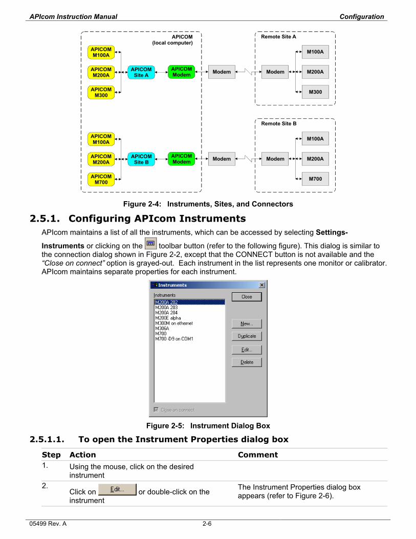
APIcom works with three distinct types of objects: instruments, sites, and connectors. The diagram below shows how these three objects (using modems as connectors) are related to each other and to the physical equipment. Other connectors can be: direct cable, RS-232 to Ethernet converter or direct Ethernet connection (future instruments)
In the figure below, everything inside the box labeled “APIcom” represents APIcom program objects, not physical equipment. From left to right, the diagram shows instruments, sites, and modems. Everything else in the diagram represents physical equipment. Notice how APIcom program objects mirror the arrangement of the physical equipment.
05499 Rev. A 2-5
APIcom Instruction Manual Configuration
M100A
M200A
M200AAPICOMM200A
APICOMM200A
M100A
APICOMM100A
APICOMM100A
M300APICOMM300
Modem
Remote Site A
Remote Site B
APICOM(local computer)
ModemModem
Modem
APICOMSite B
APICOMModem
APICOMModem
APICOMSite A
M700APICOMM700
Figure 2-4: Instruments, Sites, and Connectors
2.5.1. Configuring APIcom Instruments APIcom maintains a list of all the instruments, which can be accessed by selecting Settings-
Instruments or clicking on the toolbar button (refer to the following figure). This dialog is similar to the connection dialog shown in Figure 2-2, except that the CONNECT button is not available and the “Close on connect” option is grayed-out. Each instrument in the list represents one monitor or calibrator. APIcom maintains separate properties for each instrument.
Figure 2-5: Instrument Dialog Box
2.5.1.1. To open the Instrument Properties dialog box
Step Action Comment 1. Using the mouse, click on the desired
instrument
2. Click on or double-click on the instrument
The Instrument Properties dialog box appears (refer to Figure 2-6).
05499 Rev. A 2-6
APIcom Instruction Manual Configuration
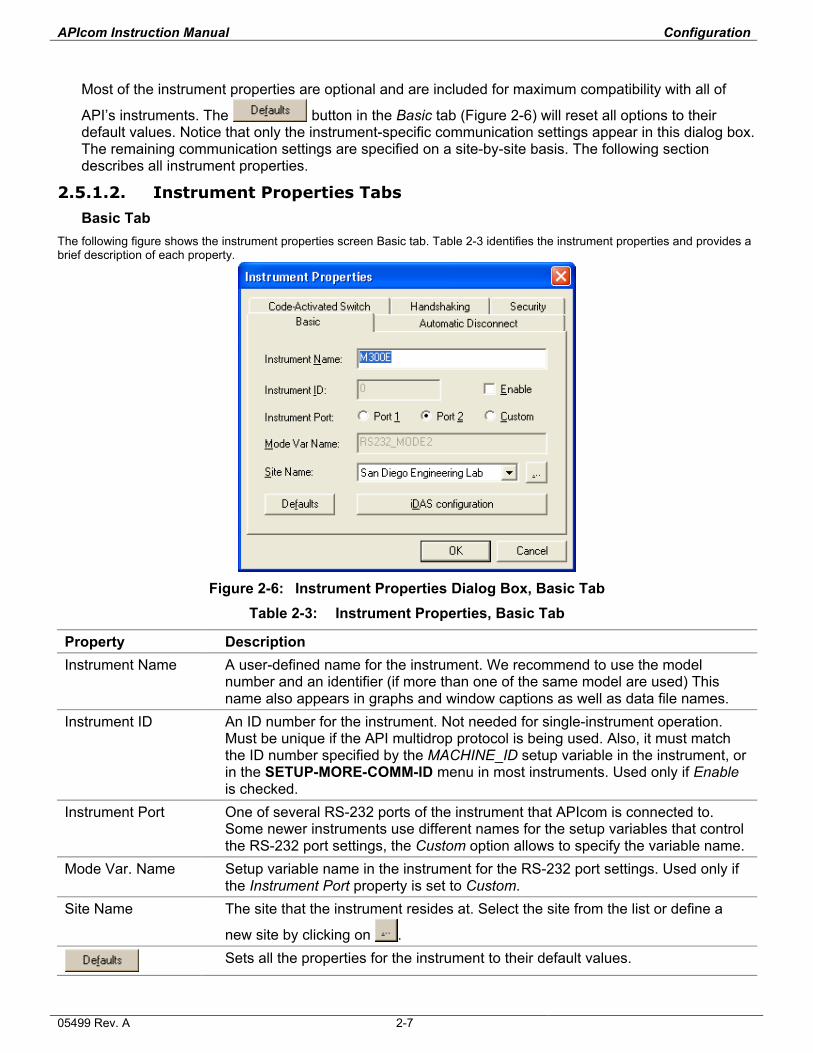
Most of the instrument properties are optional and are included for maximum compatibility with all of
API’s instruments. The button in the Basic tab (Figure 2-6) will reset all options to their default values. Notice that only the instrument-specific communication settings appear in this dialog box. The remaining communication settings are specified on a site-by-site basis. The following section describes all instrument properties.
2.5.1.2. Instrument Properties Tabs
Basic Tab The following figure shows the instrument properties screen Basic tab. Table 2-3 identifies the instrument properties and provides a brief description of each property.
Figure 2-6: Instrument Properties Dialog Box, Basic Tab
Table 2-3: Instrument Properties, Basic Tab
Property Description Instrument Name A user-defined name for the instrument. We recommend to use the model
number and an identifier (if more than one of the same model are used) This name also appears in graphs and window captions as well as data file names.
Instrument ID An ID number for the instrument. Not needed for single-instrument operation. Must be unique if the API multidrop protocol is being used. Also, it must match the ID number specified by the MACHINE_ID setup variable in the instrument, or in the SETUP-MORE-COMM-ID menu in most instruments. Used only if Enable is checked.
Instrument Port One of several RS-232 ports of the instrument that APIcom is connected to. Some newer instruments use different names for the setup variables that control the RS-232 port settings, the Custom option allows to specify the variable name.
Mode Var. Name Setup variable name in the instrument for the RS-232 port settings. Used only if the Instrument Port property is set to Custom.
Site Name The site that the instrument resides at. Select the site from the list or define a
new site by clicking on .
Sets all the properties for the instrument to their default values.
05499 Rev. A 2-7
APIcom Instruction Manual Configuration
Property Description iDAS configuration
Permits off-line editing of the instrument’s iDAS configuration. Enabled only if instrument has iDAS and APIcom was connected to the instrument and downloaded its iDAS configuration at least once. After connecting to an instrument, it takes a few seconds to make this option available. During this time, APIcom does not respond to any user input.
Sequence configuration
Permits off-line editing of the instrument’s sequence configuration. Enabled only if instrument is an M700 and APIcom was connected to it and downloaded its sequence configuration at least once. Also takes several seconds to become available.
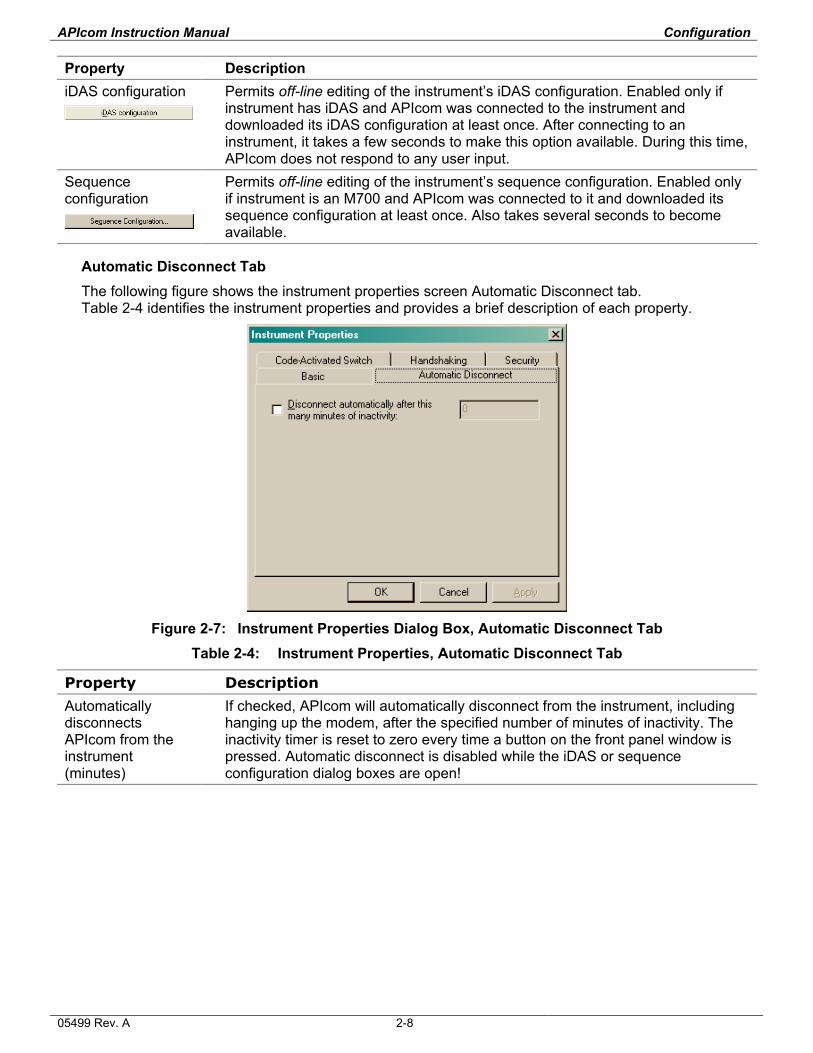
Automatic Disconnect Tab The following figure shows the instrument properties screen Automatic Disconnect tab. Table 2-4 identifies the instrument properties and provides a brief description of each property.
Figure 2-7: Instrument Properties Dialog Box, Automatic Disconnect Tab
Table 2-4: Instrument Properties, Automatic Disconnect Tab
Property Description
Automatically disconnects APIcom from the instrument (minutes)
If checked, APIcom will automatically disconnect from the instrument, including hanging up the modem, after the specified number of minutes of inactivity. The inactivity timer is reset to zero every time a button on the front panel window is pressed. Automatic disconnect is disabled while the iDAS or sequence configuration dialog boxes are open!
05499 Rev. A 2-8
APIcom Instruction Manual Configuration
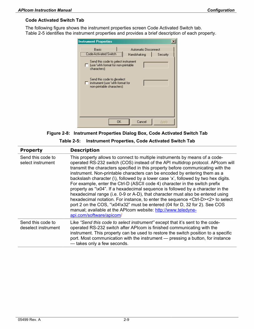
Code Activated Switch Tab The following figure shows the instrument properties screen Code Activated Switch tab. Table 2-5 identifies the instrument properties and provides a brief description of each property.
Figure 2-8: Instrument Properties Dialog Box, Code Activated Switch Tab
Table 2-5: Instrument Properties, Code Activated Switch Tab
Property Description
Send this code to select instrument
This property allows to connect to multiple instruments by means of a code-operated RS-232 switch (COS) instead of the API multidrop protocol. APIcom will transmit the characters specified in this property before communicating with the instrument. Non-printable characters can be encoded by entering them as a backslash character (\), followed by a lower case ‘x’, followed by two hex digits. For example, enter the Ctrl-D (ASCII code 4) character in the switch prefix property as “\x04”. If a hexadecimal sequence is followed by a character in the hexadecimal range (i.e. 0-9 or A-D), that character must also be entered using hexadecimal notation. For instance, to enter the sequence <Ctrl-D><2> to select port 2 on the COS, “\x04\x32” must be entered (04 for D, 32 for 2). See COS manual; available at the APIcom website: http://www.teledyne-api.com/software/apicom/
Send this code to deselect instrument
Like “Send this code to select instrument” except that it’s sent to the code-operated RS-232 switch after APIcom is finished communicating with the instrument. This property can be used to restore the switch position to a specific port. Most communication with the instrument — pressing a button, for instance — takes only a few seconds.
05499 Rev. A 2-9
APIcom Instruction Manual Configuration
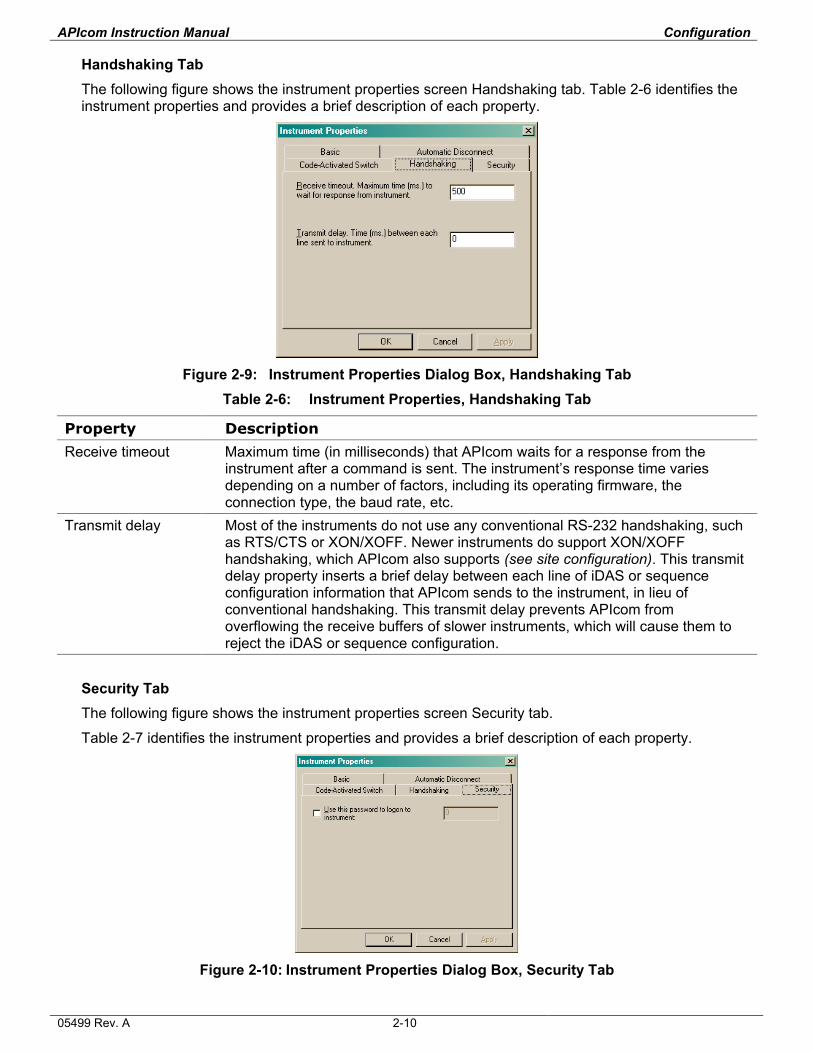
Handshaking Tab The following figure shows the instrument properties screen Handshaking tab. Table 2-6 identifies the instrument properties and provides a brief description of each property.
Figure 2-9: Instrument Properties Dialog Box, Handshaking Tab
Table 2-6: Instrument Properties, Handshaking Tab
Property Description
Receive timeout Maximum time (in milliseconds) that APIcom waits for a response from the instrument after a command is sent. The instrument’s response time varies depending on a number of factors, including its operating firmware, the connection type, the baud rate, etc.
Transmit delay Most of the instruments do not use any conventional RS-232 handshaking, such as RTS/CTS or XON/XOFF. Newer instruments do support XON/XOFF handshaking, which APIcom also supports (see site configuration). This transmit delay property inserts a brief delay between each line of iDAS or sequence configuration information that APIcom sends to the instrument, in lieu of conventional handshaking. This transmit delay prevents APIcom from overflowing the receive buffers of slower instruments, which will cause them to reject the iDAS or sequence configuration.
Security Tab The following figure shows the instrument properties screen Security tab.
Table 2-7 identifies the instrument properties and provides a brief description of each property.
Figure 2-10: Instrument Properties Dialog Box, Security Tab
05499 Rev. A 2-10
APIcom Instruction Manual Configuration
Table 2-7: Instrument Properties, Security Tab
Property Description
Use this password to logon to an instrument
If checked, APIcom will use the specified password to logon to the instrument when establishing a connection. Most of API’s instruments have some password mode in which the instrument will only accept commands after a password has been submitted. Also refer to the section titled Modems below.
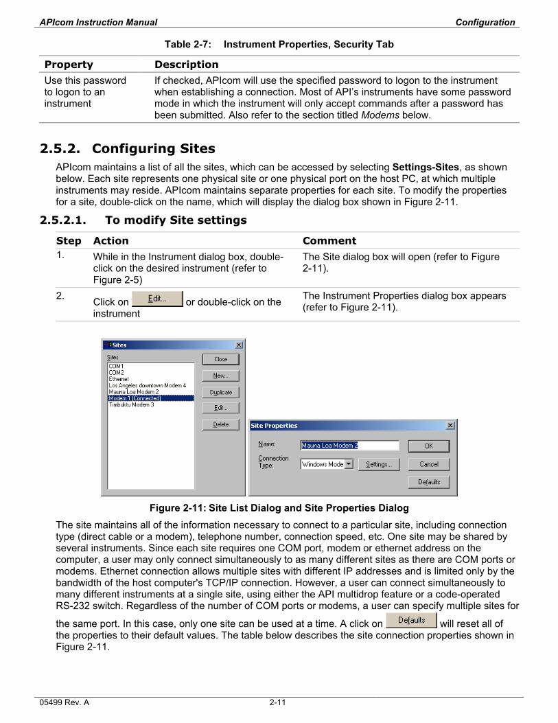
2.5.2. Configuring Sites APIcom maintains a list of all the sites, which can be accessed by selecting Settings-Sites, as shown below. Each site represents one physical site or one physical port on the host PC, at which multiple instruments may reside. APIcom maintains separate properties for each site. To modify the properties for a site, double-click on the name, which will display the dialog box shown in Figure 2-11.
2.5.2.1. To modify Site settings
Step Action Comment 1. While in the Instrument dialog box, double-
click on the desired instrument (refer to Figure 2-5)
The Site dialog box will open (refer to Figure 2-11).
2. Click on or double-click on the instrument
The Instrument Properties dialog box appears (refer to Figure 2-11).
Figure 2-11: Site List Dialog and Site Properties Dialog
The site maintains all of the information necessary to connect to a particular site, including connection type (direct cable or a modem), telephone number, connection speed, etc. One site may be shared by several instruments. Since each site requires one COM port, modem or ethernet address on the computer, a user may only connect simultaneously to as many different sites as there are COM ports or modems. Ethernet connection allows multiple sites with different IP addresses and is limited only by the bandwidth of the host computer's TCP/IP connection. However, a user can connect simultaneously to many different instruments at a single site, using either the API multidrop feature or a code-operated RS-232 switch. Regardless of the number of COM ports or modems, a user can specify multiple sites for
the same port. In this case, only one site can be used at a time. A click on will reset all of the properties to their default values. The table below describes the site connection properties shown in Figure 2-11.
05499 Rev. A 2-11
APIcom Instruction Manual Configuration
Table 2-8: Site Properties
Property Description
Name A user-defined name for the site. The name appears in graphs and window captions. The site name is combined with the instrument name to form a title for dialog boxes and graphs. For example, a “M300E” instrument name and a “San Francisco Lab” site name are combined for front panel window titles such as “M300E at San Francisco Lab”
Connection Type Selects whether the connection is made by means of a direct cable, modem or by TCP/IP (Ethernet). Two kinds of modems are supported: Windows (TAPI) modems and non-Windows modems. The use of Windows modems is recommended, however, some older modems may not be supported by Windows. In these cases, the non-Windows modem support can be used. The TCP/IP option is an experimental implementation only at this time and is supported only for a few specific RS-232 to Ethernet converters. Once a connection type is selected, it must be configured by clicking on
.
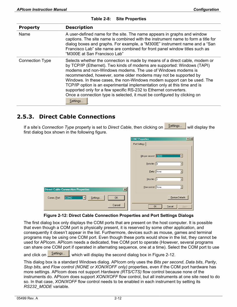
2.5.3. Direct Cable Connections
If a site’s Connection Type property is set to Direct Cable, then clicking on will display the first dialog box shown in the following figure.
Figure 2-12: Direct Cable Connection Properties and Port Settings Dialogs
The first dialog box only displays the COM ports that are present on the host computer. It is possible that even though a COM port is physically present, it is reserved by some other application, and consequently it doesn’t appear in the list. Furthermore, devices such as mouse, games and terminal programs may be using one COM port. Even though these ports would show in the list, they cannot be used for APIcom. APIcom needs a dedicated, free COM port to operate (However, several programs can share one COM port if operated in alternating sequence, one at a time). Select the COM port to use
and click on , which will display the second dialog box in Figure 2-12.
This dialog box is a standard Windows dialog. APIcom only uses the Bits per second, Data bits, Parity, Stop bits, and Flow control (NONE or XON/XOFF only) properties, even if the COM port hardware has more settings. APIcom does not support Hardware (RTS/CTS) flow control because none of the instruments do. APIcom does support XON/XOFF flow control, but all instruments at one site need to do so. In that case, XON/XOFF flow control needs to be enabled in each instrument by setting its RS232_MODE variable.
05499 Rev. A 2-12
APIcom Instruction Manual Configuration
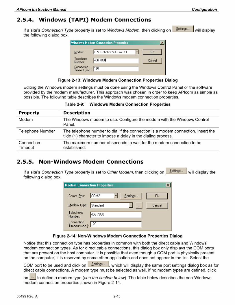
2.5.4. Windows (TAPI) Modem Connections
If a site’s Connection Type property is set to Windows Modem, then clicking on will display the following dialog box.
Figure 2-13: Windows Modem Connection Properties Dialog
Editing the Windows modem settings must be done using the Windows Control Panel or the software provided by the modem manufacturer. This approach was chosen in order to keep APIcom as simple as possible. The following table describes the Windows modem connection properties.
Table 2-9: Windows Modem Connection Properties
Property Description
Modem The Windows modem to use. Configure the modem with the Windows Control Panel.
Telephone Number The telephone number to dial if the connection is a modem connection. Insert the tilde (~) character to impose a delay in the dialing process.
Connection Timeout
The maximum number of seconds to wait for the modem connection to be established.
2.5.5. Non-Windows Modem Connections
If a site’s Connection Type property is set to Other Modem, then clicking on will display the following dialog box.
Figure 2-14: Non-Windows Modem Connection Properties Dialog
Notice that this connection type has properties in common with both the direct cable and Windows modem connection types. As for direct cable connections, this dialog box only displays the COM ports that are present on the host computer. It is possible that even though a COM port is physically present on the computer, it is reserved by some other application and does not appear in the list. Select the
COM port to be used and click on , which will display the same port settings dialog box as for direct cable connections. A modem type must be selected as well. If no modem types are defined, click
on to define a modem type (see the section below). The table below describes the non-Windows modem connection properties shown in Figure 2-14.
05499 Rev. A 2-13
APIcom Instruction Manual Configuration
Table 2-10: Non-Windows Modem Connection Properties
Property Description
Comm. Port The COM port on the computer that the modem is attached to. Most internal modems emulate a COM port. Consult the modem documentation or the Windows Control Panel to determine which COM port the modem emulates.
Modem Type The modem type to use. Click on to define or edit a modem type. Telephone Number The telephone number to dial if the connection is a modem connection. Insert
the tilde (~) character to impose a delay in the dialing process. Connection Timeout
The maximum number of seconds to wait for the modem connection to be established.
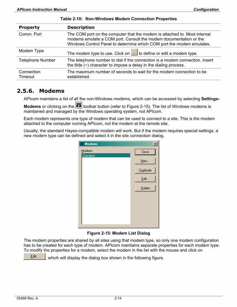
2.5.6. Modems APIcom maintains a list of all the non-Windows modems, which can be accessed by selecting Settings-
Modems or clicking on the toolbar button (refer to Figure 2-15). The list of Windows modems is maintained and managed by the Windows operating system, not APIcom.
Each modem represents one type of modem that can be used to connect to a site. This is the modem attached to the computer running APIcom, not the modem at the remote site.
Usually, the standard Hayes-compatible modem will work. But if the modem requires special settings, a new modem type can be defined and select it in the site connection dialog.
Figure 2-15: Modem List Dialog
The modem properties are shared by all sites using that modem type, so only one modem configuration has to be created for each type of modem. APIcom maintains separate properties for each modem type. To modify the properties for a modem, select the modem in the list with the mouse and click on
, which will display the dialog box shown in the following figure.
05499 Rev. A 2-14
APIcom Instruction Manual Configuration
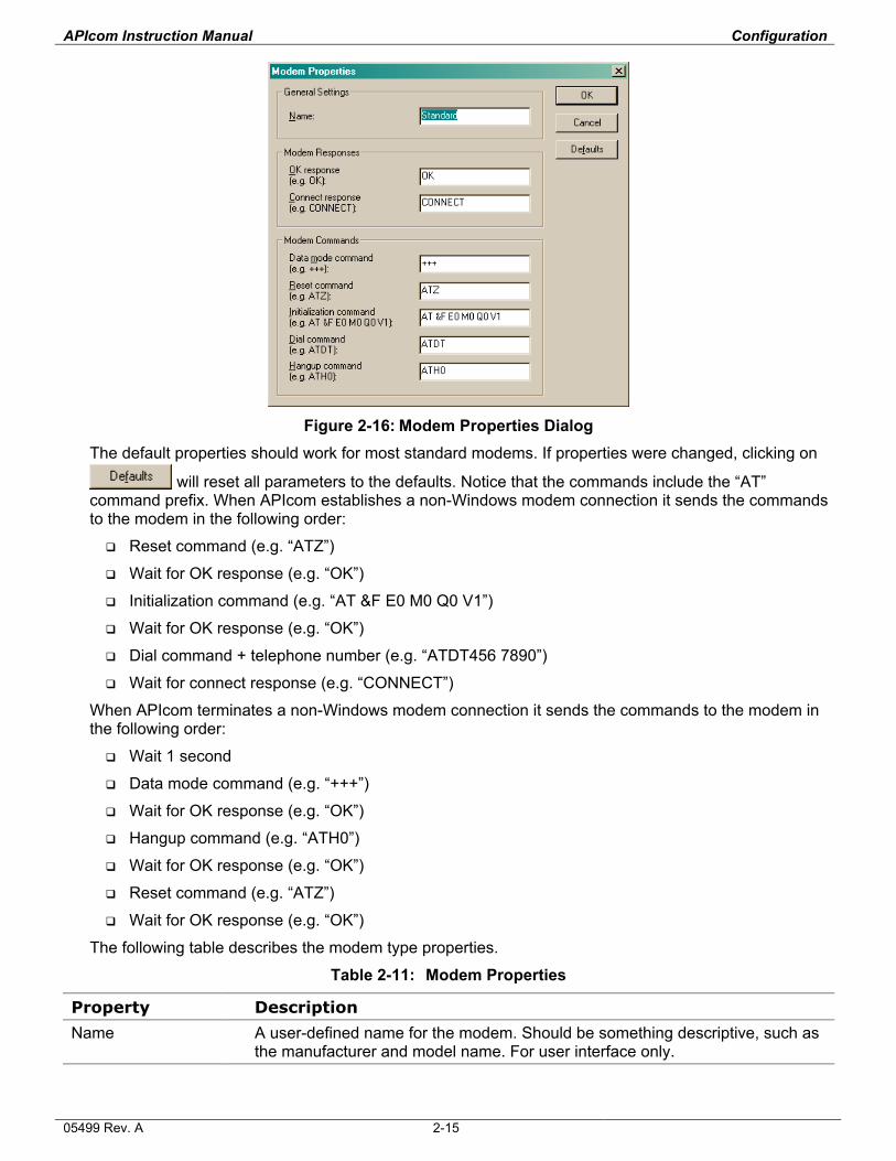
Figure 2-16: Modem Properties Dialog
The default properties should work for most standard modems. If properties were changed, clicking on
will reset all parameters to the defaults. Notice that the commands include the “AT” command prefix. When APIcom establishes a non-Windows modem connection it sends the commands to the modem in the following order:
Reset command (e.g. “ATZ”)
Wait for OK response (e.g. “OK”)
Initialization command (e.g. “AT &F E0 M0 Q0 V1”)
Wait for OK response (e.g. “OK”)
Dial command + telephone number (e.g. “ATDT456 7890”)
Wait for connect response (e.g. “CONNECT”)
When APIcom terminates a non-Windows modem connection it sends the commands to the modem in the following order:
Wait 1 second
Data mode command (e.g. “+++”)
Wait for OK response (e.g. “OK”)
Hangup command (e.g. “ATH0”)
Wait for OK response (e.g. “OK”)
Reset command (e.g. “ATZ”)
Wait for OK response (e.g. “OK”)
The following table describes the modem type properties.
Table 2-11: Modem Properties
Property Description
Name A user-defined name for the modem. Should be something descriptive, such as the manufacturer and model name. For user interface only.
05499 Rev. A 2-15
APIcom Instruction Manual Configuration
Property Description
OK response The string that the modem sends to APIcom to indicate successful execution of a command.
Connect response The string that the modem sends to APIcom to indicate that a connection has been established.
Data mode command
The command that switches the modem from online mode into data mode.
Reset command The command that resets the modem to its power up state. Initialization command
The command that initializes the modem.
Dial command The command that tells the modem to dial a telephone number, using either tone or pulse dialing.
Hangup command The command that tells the modem to hang up.
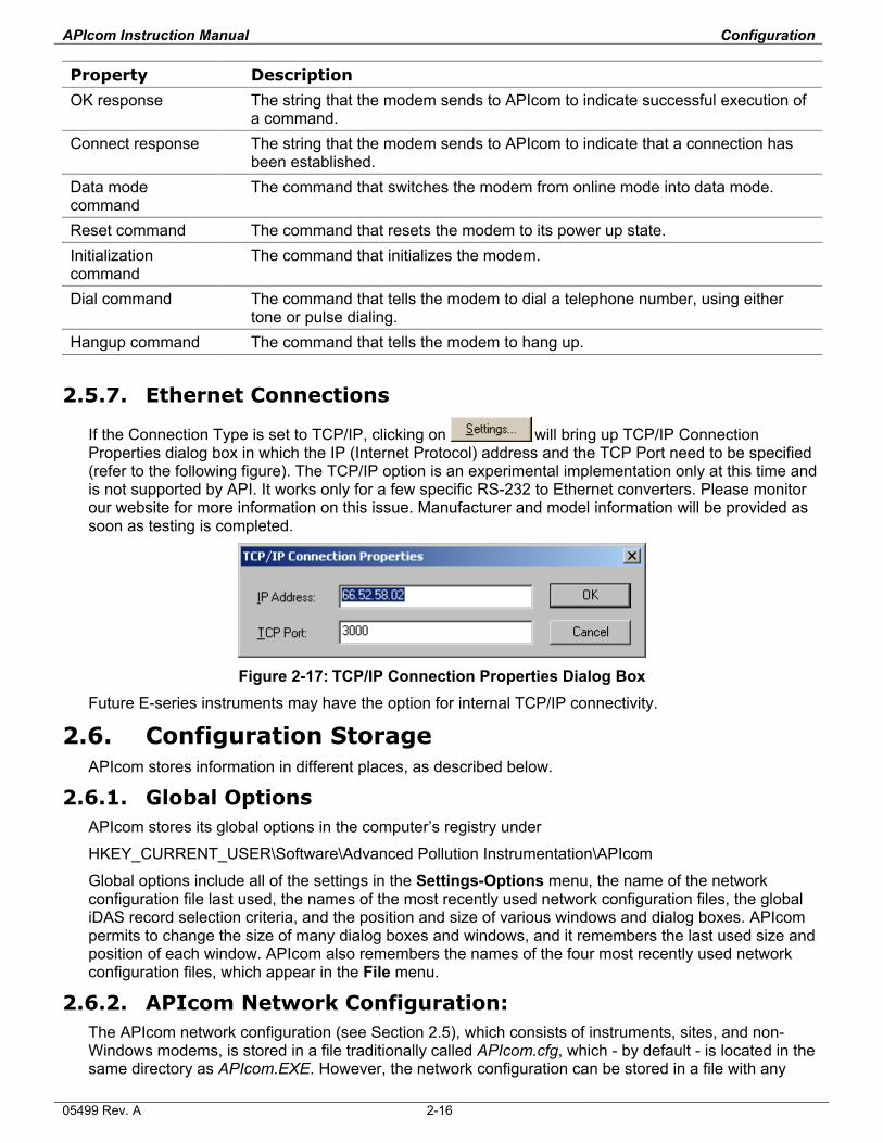
2.5.7. Ethernet Connections
If the Connection Type is set to TCP/IP, clicking on will bring up TCP/IP Connection Properties dialog box in which the IP (Internet Protocol) address and the TCP Port need to be specified (refer to the following figure). The TCP/IP option is an experimental implementation only at this time and is not supported by API. It works only for a few specific RS-232 to Ethernet converters. Please monitor our website for more information on this issue. Manufacturer and model information will be provided as soon as testing is completed.
Figure 2-17: TCP/IP Connection Properties Dialog Box
Future E-series instruments may have the option for internal TCP/IP connectivity.
2.6. Configuration Storage APIcom stores information in different places, as described below.
2.6.1. Global Options APIcom stores its global options in the computer’s registry under
HKEY_CURRENT_USER\Software\Advanced Pollution Instrumentation\APIcom
Global options include all of the settings in the Settings-Options menu, the name of the network configuration file last used, the names of the most recently used network configuration files, the global iDAS record selection criteria, and the position and size of various windows and dialog boxes. APIcom permits to change the size of many dialog boxes and windows, and it remembers the last used size and position of each window. APIcom also remembers the names of the four most recently used network configuration files, which appear in the File menu.
2.6.2. APIcom Network Configuration: The APIcom network configuration (see Section 2.5), which consists of instruments, sites, and non-Windows modems, is stored in a file traditionally called APIcom.cfg, which - by default - is located in the same directory as APIcom.EXE. However, the network configuration can be stored in a file with any
05499 Rev. A 2-16
APIcom Instruction Manual Configuration
name and a .CFG extension in any location on disk or a local area network. This enables to create different configuration files to represent different networks and to share configuration settings with other users.
APIcom also stores the iDAS or sequence configuration for each instrument in this file. This allows you to create predefined standard iDAS and sequence configurations and easily upload them to an instrument upon connection. These configurations can also be edited offline after they were created or downloaded without connecting to an instrument. Maintaining different .CFG files allows to create any number of instruments, each with distinct names, and various configurations to suit all needs.
2.6.3. APIcom Network Configuration File Types APIcom supports two different network configuration file formats: a binary format (.CFG) and a text format (.CFX). The binary format is used for operation and the text format is provided for future versions of APIcom to be able to read configurations created by earlier versions. Configurations can be stored in either format for APIcom to work. However, the .CFX format stores only the instrument, site, and modem configuration. It does not store the iDAS and sequence configuration for an instrument. To store the iDAS and sequence configuration for each instrument, the .CFG format must be used.
To save a configuration in the text format, select File–Save As and select Text network configuration
Files from the Save as type drop-down field. Enter the file name, and click on .
NOTE .CFX configuration files should not be directly edited because syntax or typographical errors could render a configuration file unreadable by APIcom or the instrument.
APIcom displays the name of the currently used configuration file in the title bar of its main application window.
APIcom also indicates that a configuration has been modified by appending “(Modified)” to the configuration file name in the application’s title bar:
2.6.4. Saving Network Configuration Files
The current network configuration can be saved at any time by clicking on the toolbar button or by selecting File-Save from the main menu.
APIcom will automatically save modified configuration files upon exiting if that option was enabled in the Settings-Options menu. However, if that option was not enabled and the configuration has been modified before exiting the program, APIcom will prompt to save the changes.
Opening Network Configuration Files With Windows Shortcuts
Different network configurations can be maintained and easily used by creating a Windows shortcut that specifies the configuration file on APIcom’s command line. A user could, for example, create a different icon on the desktop to represent each network configuration. To do this, simply locate the .CFG file and right-click and drag the icon to the desktop, then select "Create Shortcut" from the menu.
05499 Rev. A 2-17

3. BASIC OPERATION
3.1. Connecting to an Instrument
To connect to an instrument and display its Front Panel Window, click on , type Ctrl-C on the computer keyboard, or select File-Connect from the Main Application Window. See Figure 2-2 for an example of the connection dialog box.
There are three ways to establish the connection:
Select an instrument from the list and click on .
Press Enter on the computer keyboard.
Double-click an the instrument name in the list.
If the “Close on connect” option at the bottom of the connection dialog is checked, the dialog window will automatically close while APIcom establishes the connection. If this option is not checked, the dialog will remain open, permitting the user to initiate several connections in one step.
If the connection is via a direct cable, the Front Panel Window should promptly display the contents of the instrument’s physical display. If the connection is via a modem, it will take some time for APIcom to dial the remote site. Ethernet connection speed may vary depending on the internet speed.
APIcom establishes the front panel first and then connects to the underlying software. The front panel cannot be used until the button Download, graph, save data… is displayed in black. Older instruments without this functionality can be used right away.
APIcom may not be able to connect to the instrument for many reasons. The wrong COM port or settings may be in use. The cable may be the wrong type or low quality. The wrong modem type may be selected. The connection may be a direct cable connection when it should be a modem connection. The cables may not be attached. The instrument ID may be incorrect. A switch prefix may be in use when it should not be, or is not in use when it should be.
3.2. Front Panel Buttons A button on the Front Panel Window can be activated two different ways: by clicking on the button with the mouse, or by typing key 1–8 on the computer keyboard. As buttons on the Front Panel Window are activated, the graphical display changes.
NOTE While using APIcom, be careful not to change any setting that may affect the RS-232 connection, such as the RS-232 mode, the baud rate, or the instrument ID number.
3.3. Disconnecting From an Instrument To disconnect from an instrument, press the Esc key on the computer keyboard while the Front Panel Window is displayed, or click on in the upper right hand corner of the Front Panel Window. APIcom will prompt for confirmation and will also prompt if the iDAS settings were changed without saving or uploading them. When all instruments from a particular site are closed, the site and modem connection is closed, too.
3.4. Exiting APIcom To exit APIcom, press Alt-F4 on the computer keyboard while the Main Application Window is displayed (see Figure 2-1), or click on in the upper right hand corner of the Main Application Window or select File-Exit from the main menu.
APIcom will prompt the user if there is any front panel left open and if the network configuration file was changed and not yet saved.
05499 Rev. A 3-1
APIcom Instruction Manual Basic Operation
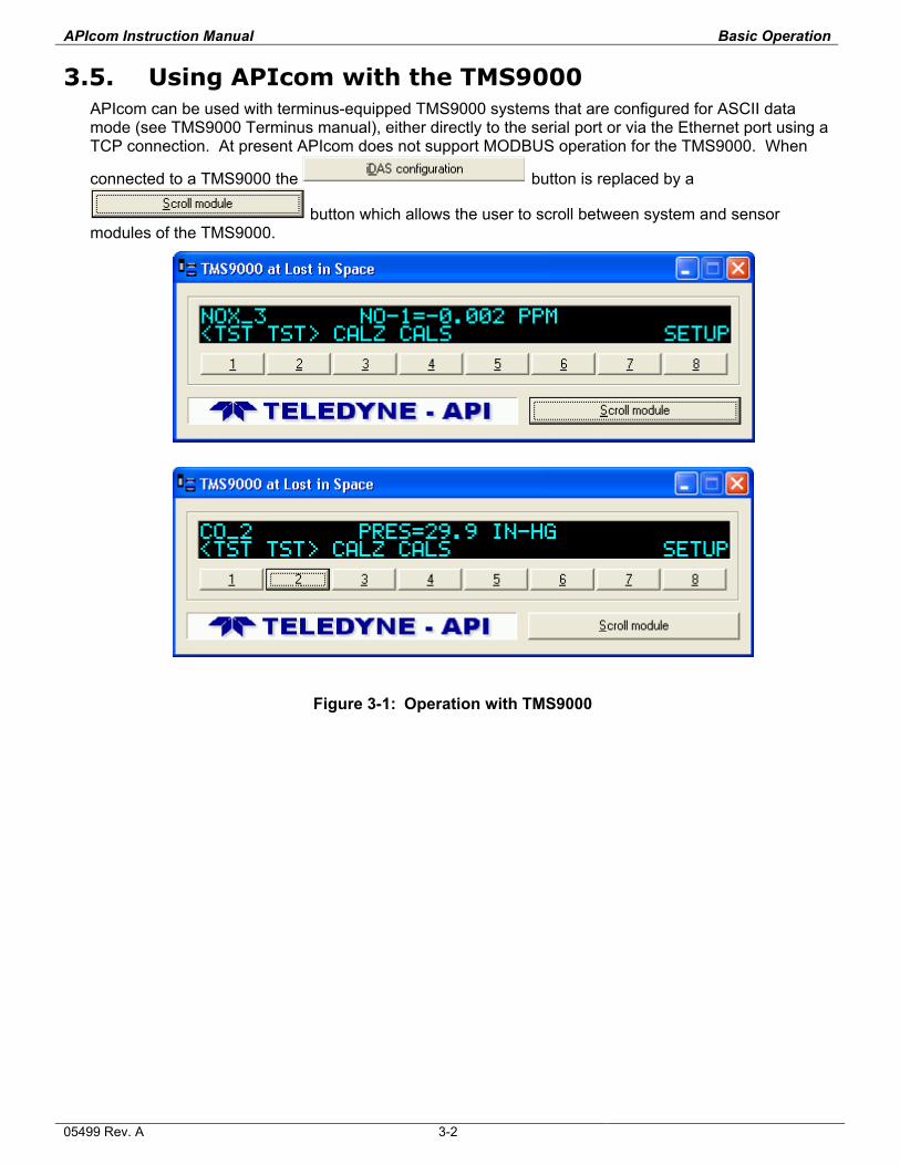
3.5. Using APIcom with the TMS9000 APIcom can be used with terminus-equipped TMS9000 systems that are configured for ASCII data mode (see TMS9000 Terminus manual), either directly to the serial port or via the Ethernet port using a TCP connection. At present APIcom does not support MODBUS operation for the TMS9000. When
connected to a TMS9000 the
button is replaced by a
button which allows the user to scroll between system and sensor modules of the TMS9000.
Figure 3-1: Operation with TMS9000
05499 Rev. A 3-2
4. iDAS CONFIGURATION AND DATA ACCESS
A major feature of APIcom is its ability to modify the built-in iDAS configuration and access the iDAS data in a remote instrument. The current instrument configuration can be downloaded, modified, and then sent back to the instrument. Once the iDAS configuration was downloaded, it can be edited off-line, saving money on long distance phone connections to the instrument. For more information on the instrument's iDAS, see the iDAS manual, API part # 02837A, available for download at:
http://advpol.com/manuals/
NOTE Sending a iDAS configuration to the instrument will completely replace its existing configuration and discard all of the instrument's stored data. We suggest that you download any data and save both data and the configuration on local disk before making any changes to the iDAS.
iDAS data can be safely downloaded, graphed and saved in a file without discarding the configuration or data in the instrument. The iDAS configuration can also be changed by using the instrument’s own menus through the Front Panel Window by pressing the appropriate buttons. Changing the configuration using the instrument’s own menus will only discard data stored in the instrument if the number of records or parameters is changed. APIcom can also be used to automatically download data in unattended mode and to append the data to existing files (see Section 4.12).
4.1. Supported Instruments The iDAS capability of APIcom is only supported by AMX-based analyzers, not calibrators, as shown in Table 4-1. Remote iDAS configuration is only supported in AMX instruments with library revision 2.1 or higher. Check the library revision of an instrument by pressing SETUP-CFG or in the Instrument Information Dialog. Please see Appendix A or the APIcom website for compatibility issues on advanced iDAS functionality: http://www.teledyne-api.com/software/apicom.html
Table 4-1: Instruments Containing iDAS
Instrument
M100A-AMX M265A-AMX M101A-AMX M300-AMX M102A-AMX M400-AMX M200A-AMX M400A-AMX
All E-Series Products TMS-9000
Upon connection to an instrument, APIcom attempts to determine if that instrument contains the iDAS
capability, and if so, it enables the
button in the Front Panel Window (see Figure 1-1). If this button is not enabled even though the instrument has the iDAS capability, simply disconnect from the instrument and reconnect.
4.2. iDAS Configuration and Downloaded Data Dialog
Click on
in the Front Panel Window (see Figure 1-1) or select Download, graph, save data… in the system menu (icon in the top-left corner of the instrument window) to display the following dialog box:
05499 Rev. A 4-1
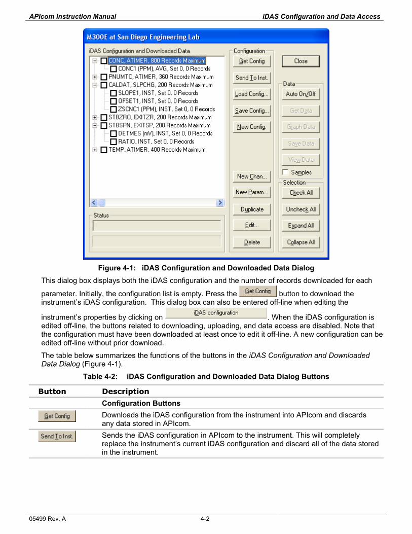
APIcom Instruction Manual iDAS Configuration and Data Access
Figure 4-1: iDAS Configuration and Downloaded Data Dialog
This dialog box displays both the iDAS configuration and the number of records downloaded for each
parameter. Initially, the configuration list is empty. Press the button to download the instrument’s iDAS configuration. This dialog box can also be entered off-line when editing the
instrument’s properties by clicking on
. When the iDAS configuration is edited off-line, the buttons related to downloading, uploading, and data access are disabled. Note that the configuration must have been downloaded at least once to edit it off-line. A new configuration can be edited off-line without prior download.
The table below summarizes the functions of the buttons in the iDAS Configuration and Downloaded Data Dialog (Figure 4-1).
Table 4-2: iDAS Configuration and Downloaded Data Dialog Buttons
Button Description
Configuration Buttons
Downloads the iDAS configuration from the instrument into APIcom and discards any data stored in APIcom.
Sends the iDAS configuration in APIcom to the instrument. This will completely replace the instrument’s current iDAS configuration and discard all of the data stored in the instrument.
05499 Rev. A 4-2
APIcom Instruction Manual iDAS Configuration and Data Access
Button Description
Loads the iDAS configuration from a text file stored on the computer. This configuration may be edited and saved on the computer again, or it may be sent to an instrument. This configuration file may have been downloaded from the instrument using the “D PRINT SCRIPT” RS-232 command, or it may have been
created using the button in APIcom.
Saves the iDAS configuration to a text file on the computer. This configuration file is suitable for uploading to the instrument via its RS-232 interface.
Creates a new, empty iDAS configuration.
Creates a new channel.
Creates a new parameter on the selected channel.
Creates a duplicate of the selected channel or parameter. This button facilitates creating channels or parameters that are minor variations of existing ones. When selected, it will prompt for a new channel name. Channel names must be unique.
Edits the properties of the selected parameter or channel.
Deletes the selected parameter or channel.
Data Buttons
Turns the automatic data download feature on and off.
Downloads the data for the selected parameter or channel from the instrument.
Graphs the data for the selected parameter or channel.
Saves the data for the selected parameter or channel in a text file.
Views the data for the selected parameter or channel as a table on the computer screen.
Enables downloading, viewing, or saving the number of samples in each average. Only newer instruments support this option.
Selection Buttons
Selects all the channels and parameters in the list.
Unselects all the channels and parameters in the list.
Expands all the channels in the list, showing all the parameters.
Collapses all the channels in the list, hiding all the parameters.
4.3. Downloading the iDAS Configuration
Download the remote instrument’s iDAS configuration by clicking on . Any iDAS data that were previously downloaded by APIcom will be discarded (but are not affected within the instrument).
APIcom stores the last used iDAS configuration of any instrument in the network configuration file (.CFG). If the configuration was already downloaded from this instrument, the iDAS configuration will appear in the dialog. After downloading the iDAS configuration, which should take a few seconds, the dialog box will look similar to the following example:
05499 Rev. A 4-3
APIcom Instruction Manual iDAS Configuration and Data Access
In Figure 4-1, the channels have been expanded to show all the parameters. The dialog box displays a summary of the channels, including the channel name, the triggering event, and the maximum number of records the channel stores. The parameter summary includes the parameter name and numeric units, the sampling mode, the record set number, and the number of records actually downloaded from the instrument. Since no data have been downloaded yet, the number of records is zero for all the parameters.
4.4. Saving the iDAS Configuration Saving the iDAS configuration of any instrument to disk is useful to maintain several different measurement protocols (frequent data acquisition for trouble-shooting and engineering, long-term averages for monitoring, etc.) or simply to keep a backup when replacing the firmware of the analyzer. API provides standard and custom sample iDAS scripts at the APIcom website:
http://teledyne-api.com/software/apicom/sample_scripts.html
There are two ways to save the iDAS configuration. APIcom automatically stores the iDAS configuration in its network configuration file when the configuration file is saved. This copy is not permanent. The
second way is to save the iDAS configuration as a text file on disk. When using the button, APIcom prompts for a file name. The default file name format is:
“<Instrument Name>-< Instrument Serial Number> iDAS Configuration.txt”
This name can be changed to any other file name. Once saved as a text file, it can be loaded by using
the button or uploaded to the instrument by using APIcom ( ) or a simple terminal program.
4.5. Modifying the iDAS Configuration APIcom can only modify the iDAS configuration in AMX instruments with library revision 2.4 or higher. This section assumes familiarity with configuring the iDAS in an instrument. Refer to the built-in iDAS manual (Built-In iDAS Manual.doc) for more information on configuring the iDAS. APIcom facilitates configuring the instrument’s iDAS in the following ways:
APIcom takes advantage of the larger area of the computer screen to display more of the iDAS configuration than the instrument can on its instrument display.
APIcom validates the user’s inputs and verifies that the configuration is successfully sent to the instrument. An error message is displayed on unsuccessful upload.
APIcom allows to load iDAS configurations stored on the computer and to send them to the instrument, making it quick and easy to load the same configuration into multiple instruments.
APIcom can store many iDAS configurations on the computer, allowing a user to download different configurations for different purposes.
To download the current configuration, click on . To start a new, empty configuration, click on
. To start with a configuration that was previously saved, click on .
4.5.1. Adding or Modifying a Channel A channel can be expanded to see its parameters by clicking on the “+” boxes next to the channel names. A channel can also be expanded or collapsed by double-clicking on it. To add a new channel,
either click on or right-click on any existing channel, which will bring up the context menu shown below, and select New Channel. The maximum number of channels that can be configured is 20 per instrument. The maximum number of parameters in each channel is 10 and the maximum number of data records in each channel is 64000. However, the A-series analyzers are limited by 64 KB data memory, hence the average number of records (depending on the number of channels and parameters and if the number of samples in a concentration average is recorded) is much lower, typically around
05499 Rev. A 4-4
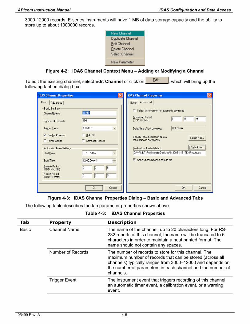
APIcom Instruction Manual iDAS Configuration and Data Access
3000-12000 records. E-series instruments will have 1 MB of data storage capacity and the ability to store up to about 1000000 records.
Figure 4-2: iDAS Channel Context Menu – Adding or Modifying a Channel
To edit the existing channel, select Edit Channel or click on , which will bring up the following tabbed dialog box.
Figure 4-3: iDAS Channel Properties Dialog – Basic and Advanced Tabs
The following table describes the tab parameter properties shown above.
Table 4-3: iDAS Channel Properties
Tab Property Description
Basic Channel Name The name of the channel, up to 20 characters long. For RS-232 reports of this channel, the name will be truncated to 6 characters in order to maintain a neat printed format. The name should not contain any spaces.
Number of Records The number of records to store for this channel. The maximum number of records that can be stored (across all channels) typically ranges from 3000–12000 and depends on the number of parameters in each channel and the number of channels.
Trigger Event The instrument event that triggers recording of this channel: an automatic timer event, a calibration event, or a warning event.
05499 Rev. A 4-5
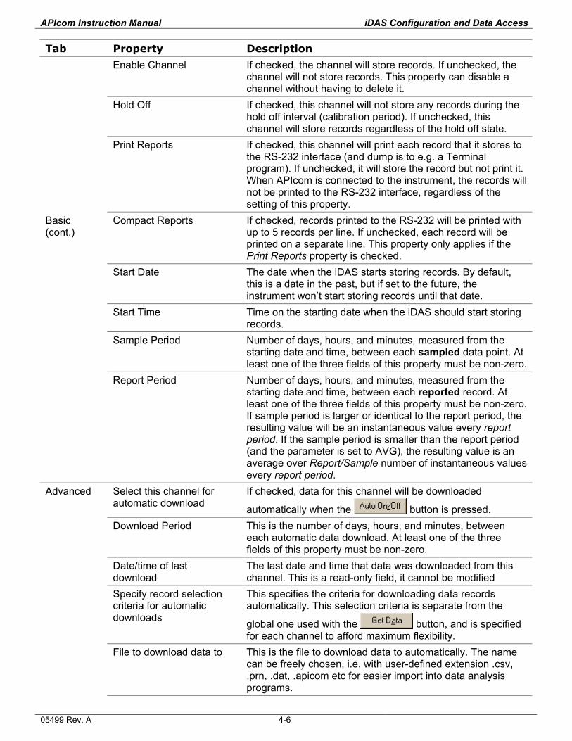
APIcom Instruction Manual iDAS Configuration and Data Access
Tab Property Description
Enable Channel If checked, the channel will store records. If unchecked, the channel will not store records. This property can disable a channel without having to delete it.
Hold Off If checked, this channel will not store any records during the hold off interval (calibration period). If unchecked, this channel will store records regardless of the hold off state.
Print Reports If checked, this channel will print each record that it stores to the RS-232 interface (and dump is to e.g. a Terminal program). If unchecked, it will store the record but not print it. When APIcom is connected to the instrument, the records will not be printed to the RS-232 interface, regardless of the setting of this property.
Basic (cont.)
Compact Reports If checked, records printed to the RS-232 will be printed with up to 5 records per line. If unchecked, each record will be printed on a separate line. This property only applies if the Print Reports property is checked.
Start Date The date when the iDAS starts storing records. By default, this is a date in the past, but if set to the future, the instrument won’t start storing records until that date.
Start Time Time on the starting date when the iDAS should start storing records.
Sample Period Number of days, hours, and minutes, measured from the starting date and time, between each sampled data point. At least one of the three fields of this property must be non-zero.
Report Period Number of days, hours, and minutes, measured from the starting date and time, between each reported record. At least one of the three fields of this property must be non-zero. If sample period is larger or identical to the report period, the resulting value will be an instantaneous value every report period. If the sample period is smaller than the report period (and the parameter is set to AVG), the resulting value is an average over Report/Sample number of instantaneous values every report period.
Advanced Select this channel for automatic download
If checked, data for this channel will be downloaded
automatically when the button is pressed. Download Period This is the number of days, hours, and minutes, between
each automatic data download. At least one of the three fields of this property must be non-zero.
Date/time of last download
The last date and time that data was downloaded from this channel. This is a read-only field, it cannot be modified
Specify record selection criteria for automatic downloads
This specifies the criteria for downloading data records automatically. This selection criteria is separate from the
global one used with the button, and is specified for each channel to afford maximum flexibility.
File to download data to This is the file to download data to automatically. The name can be freely chosen, i.e. with user-defined extension .csv, .prn, .dat, .apicom etc for easier import into data analysis programs.
05499 Rev. A 4-6
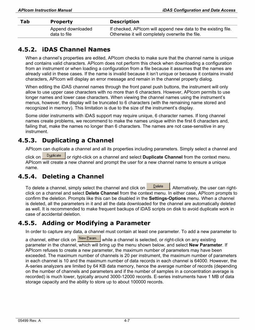
APIcom Instruction Manual iDAS Configuration and Data Access
Tab Property Description
Append downloaded data to file
If checked, APIcom will append new data to the existing file. Otherwise it will completely overwrite the file.
4.5.2. iDAS Channel Names When a channel’s properties are edited, APIcom checks to make sure that the channel name is unique and contains valid characters. APIcom does not perform this check when downloading a configuration from an instrument or when loading a configuration from a file because it assumes that the names are already valid in these cases. If the name is invalid because it isn’t unique or because it contains invalid characters, APIcom will display an error message and remain in the channel property dialog.
When editing the iDAS channel names through the front panel push buttons, the instrument will only allow to use upper case characters with no more than 6 characters. However, APIcom permits to use longer names and lower case characters. When viewing the channel names using the instrument’s menus, however, the display will be truncated to 6 characters (with the remaining name stored and recognized in memory). This limitation is due to the size of the instrument’s display.
Some older instruments with iDAS support may require unique, 6 character names. If long channel names create problems, we recommend to make the names unique within the first 6 characters and, failing that, make the names no longer than 6 characters. The names are not case-sensitive in any instrument.
4.5.3. Duplicating a Channel APIcom can duplicate a channel and all its properties including parameters. Simply select a channel and
click on or right-click on a channel and select Duplicate Channel from the context menu. APIcom will create a new channel and prompt the user for a new channel name to ensure a unique name.
4.5.4. Deleting a Channel
To delete a channel, simply select the channel and click on . Alternatively, the user can right-click on a channel and select Delete Channel from the context menu. In either case, APIcom prompts to confirm the deletion. Prompts like this can be disabled in the Settings-Options menu. When a channel is deleted, all the parameters in it and all the data downloaded for the channel are automatically deleted as well. It is recommended to make frequent backups of iDAS scripts on disk to avoid duplicate work in case of accidental deletion.
4.5.5. Adding or Modifying a Parameter In order to capture any data, a channel must contain at least one parameter. To add a new parameter to
a channel, either click on while a channel is selected, or right-click on any existing parameter in the channel, which will bring up the menu shown below, and select New Parameter. If APIcom refuses to create a new parameter, the maximum number of parameters may have been exceeded. The maximum number of channels is 20 per instrument, the maximum number of parameters in each channel is 10 and the maximum number of data records in each channel is 64000. However, the A-series analyzers are limited by 64 KB data memory, hence the average number of records (depending on the number of channels and parameters and if the number of samples in a concentration average is recorded) is much lower, typically around 3000-12000 records. E-series instruments have 1 MB of data storage capacity and the ability to store up to about 100000 records.
05499 Rev. A 4-7
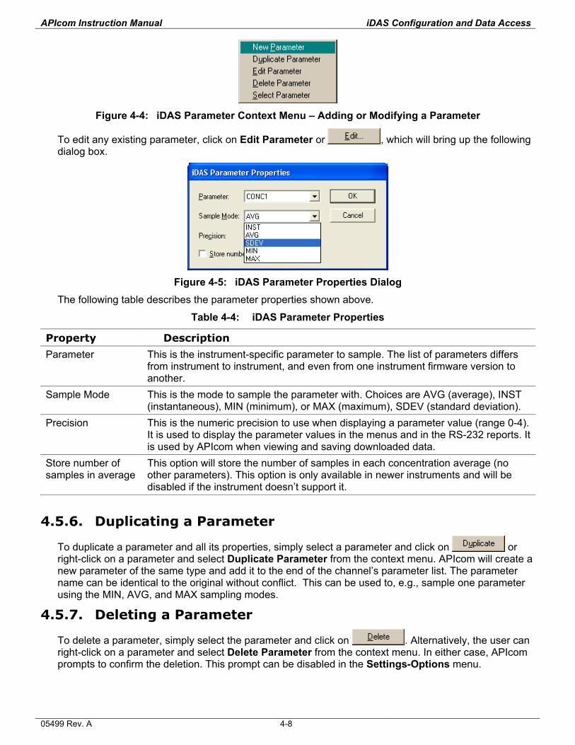
APIcom Instruction Manual iDAS Configuration and Data Access
Figure 4-4: iDAS Parameter Context Menu – Adding or Modifying a Parameter
To edit any existing parameter, click on Edit Parameter or , which will bring up the following dialog box.
Figure 4-5: iDAS Parameter Properties Dialog
The following table describes the parameter properties shown above.
Table 4-4: iDAS Parameter Properties
Property Description
Parameter This is the instrument-specific parameter to sample. The list of parameters differs from instrument to instrument, and even from one instrument firmware version to another.
Sample Mode This is the mode to sample the parameter with. Choices are AVG (average), INST (instantaneous), MIN (minimum), or MAX (maximum), SDEV (standard deviation).
Precision This is the numeric precision to use when displaying a parameter value (range 0-4). It is used to display the parameter values in the menus and in the RS-232 reports. It is used by APIcom when viewing and saving downloaded data.
Store number of samples in average
This option will store the number of samples in each concentration average (no other parameters). This option is only available in newer instruments and will be disabled if the instrument doesn’t support it.
4.5.6. Duplicating a Parameter
To duplicate a parameter and all its properties, simply select a parameter and click on or right-click on a parameter and select Duplicate Parameter from the context menu. APIcom will create a new parameter of the same type and add it to the end of the channel’s parameter list. The parameter name can be identical to the original without conflict. This can be used to, e.g., sample one parameter using the MIN, AVG, and MAX sampling modes.
4.5.7. Deleting a Parameter
To delete a parameter, simply select the parameter and click on . Alternatively, the user can right-click on a parameter and select Delete Parameter from the context menu. In either case, APIcom prompts to confirm the deletion. This prompt can be disabled in the Settings-Options menu.
05499 Rev. A 4-8
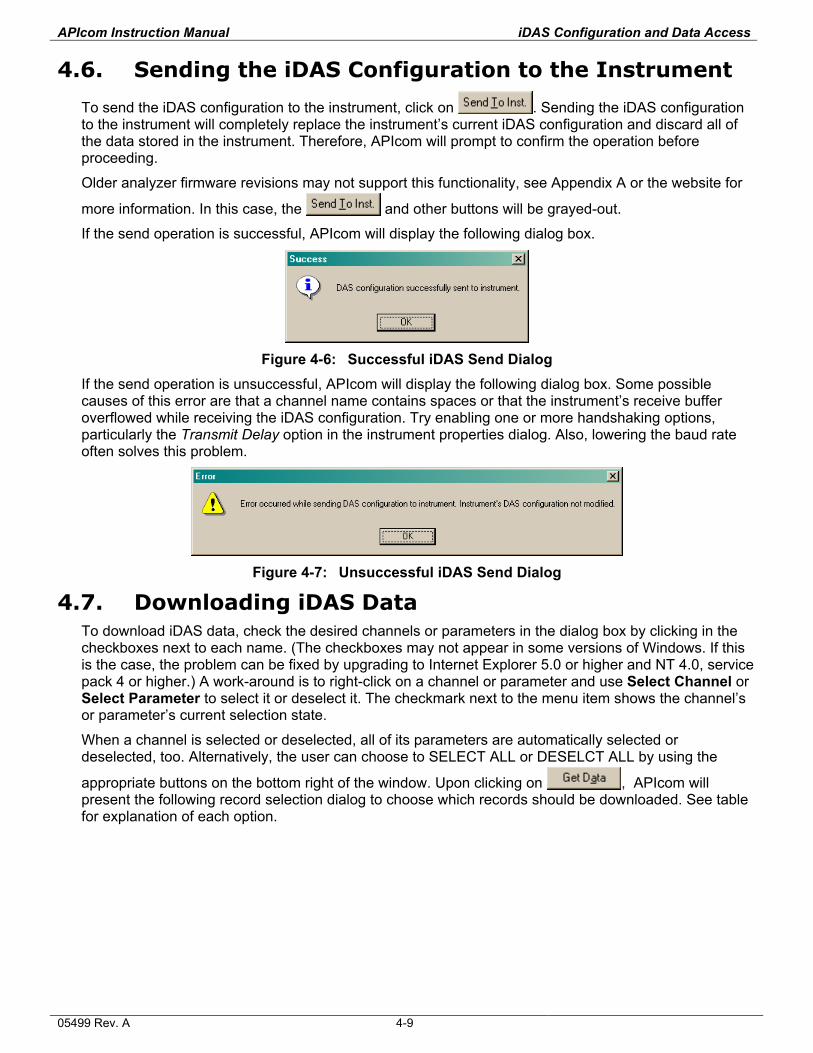
APIcom Instruction Manual iDAS Configuration and Data Access
4.6. Sending the iDAS Configuration to the Instrument
To send the iDAS configuration to the instrument, click on . Sending the iDAS configuration to the instrument will completely replace the instrument’s current iDAS configuration and discard all of the data stored in the instrument. Therefore, APIcom will prompt to confirm the operation before proceeding.
Older analyzer firmware revisions may not support this functionality, see Appendix A or the website for
more information. In this case, the and other buttons will be grayed-out.
If the send operation is successful, APIcom will display the following dialog box.
Figure 4-6: Successful iDAS Send Dialog
If the send operation is unsuccessful, APIcom will display the following dialog box. Some possible causes of this error are that a channel name contains spaces or that the instrument’s receive buffer overflowed while receiving the iDAS configuration. Try enabling one or more handshaking options, particularly the Transmit Delay option in the instrument properties dialog. Also, lowering the baud rate often solves this problem.
Figure 4-7: Unsuccessful iDAS Send Dialog
4.7. Downloading iDAS Data To download iDAS data, check the desired channels or parameters in the dialog box by clicking in the checkboxes next to each name. (The checkboxes may not appear in some versions of Windows. If this is the case, the problem can be fixed by upgrading to Internet Explorer 5.0 or higher and NT 4.0, service pack 4 or higher.) A work-around is to right-click on a channel or parameter and use Select Channel or Select Parameter to select it or deselect it. The checkmark next to the menu item shows the channel’s or parameter’s current selection state.
When a channel is selected or deselected, all of its parameters are automatically selected or deselected, too. Alternatively, the user can choose to SELECT ALL or DESELCT ALL by using the
appropriate buttons on the bottom right of the window. Upon clicking on , APIcom will present the following record selection dialog to choose which records should be downloaded. See table for explanation of each option.
05499 Rev. A 4-9
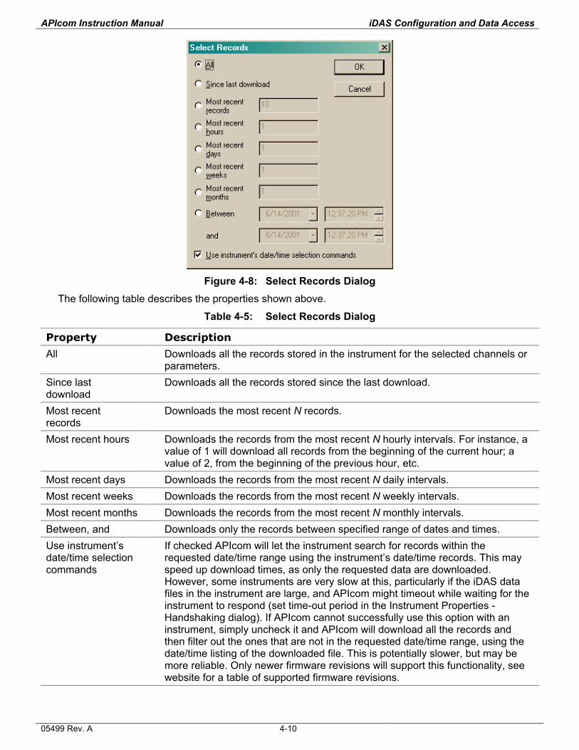
APIcom Instruction Manual iDAS Configuration and Data Access
Figure 4-8: Select Records Dialog
The following table describes the properties shown above.
Table 4-5: Select Records Dialog
Property Description
All Downloads all the records stored in the instrument for the selected channels or parameters.
Since last download
Downloads all the records stored since the last download.
Most recent records
Downloads the most recent N records.
Most recent hours Downloads the records from the most recent N hourly intervals. For instance, a value of 1 will download all records from the beginning of the current hour; a value of 2, from the beginning of the previous hour, etc.
Most recent days Downloads the records from the most recent N daily intervals. Most recent weeks Downloads the records from the most recent N weekly intervals. Most recent months Downloads the records from the most recent N monthly intervals. Between, and Downloads only the records between specified range of dates and times. Use instrument’s date/time selection commands
If checked APIcom will let the instrument search for records within the requested date/time range using the instrument’s date/time records. This may speed up download times, as only the requested data are downloaded. However, some instruments are very slow at this, particularly if the iDAS data files in the instrument are large, and APIcom might timeout while waiting for the instrument to respond (set time-out period in the Instrument Properties - Handshaking dialog). If APIcom cannot successfully use this option with an instrument, simply uncheck it and APIcom will download all the records and then filter out the ones that are not in the requested date/time range, using the date/time listing of the downloaded file. This is potentially slower, but may be more reliable. Only newer firmware revisions will support this functionality, see website for a table of supported firmware revisions.
05499 Rev. A 4-10
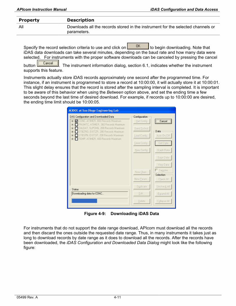
APIcom Instruction Manual iDAS Configuration and Data Access
Property Description
All Downloads all the records stored in the instrument for the selected channels or parameters.
Specify the record selection criteria to use and click on to begin downloading. Note that iDAS data downloads can take several minutes, depending on the baud rate and how many data were selected. For instruments with the proper software downloads can be canceled by pressing the cancel
button
. The instrument information dialog, section 6.1, indicates whether the instrument supports this feature.
Instruments actually store iDAS records approximately one second after the programmed time. For instance, if an instrument is programmed to store a record at 10:00:00, it will actually store it at 10:00:01. This slight delay ensures that the record is stored after the sampling interval is completed. It is important to be aware of this behavior when using the Between option above, and set the ending time a few seconds beyond the last time of desired download. For example, if records up to 10:00:00 are desired, the ending time limit should be 10:00:05.
Figure 4-9: Downloading iDAS Data
For instruments that do not support the date range download, APIcom must download all the records and then discard the ones outside the requested date range. Thus, in many instruments it takes just as long to download records by date range as it does to download all the records. After the records have been downloaded, the iDAS Configuration and Downloaded Data Dialog might look like the following figure:
05499 Rev. A 4-11
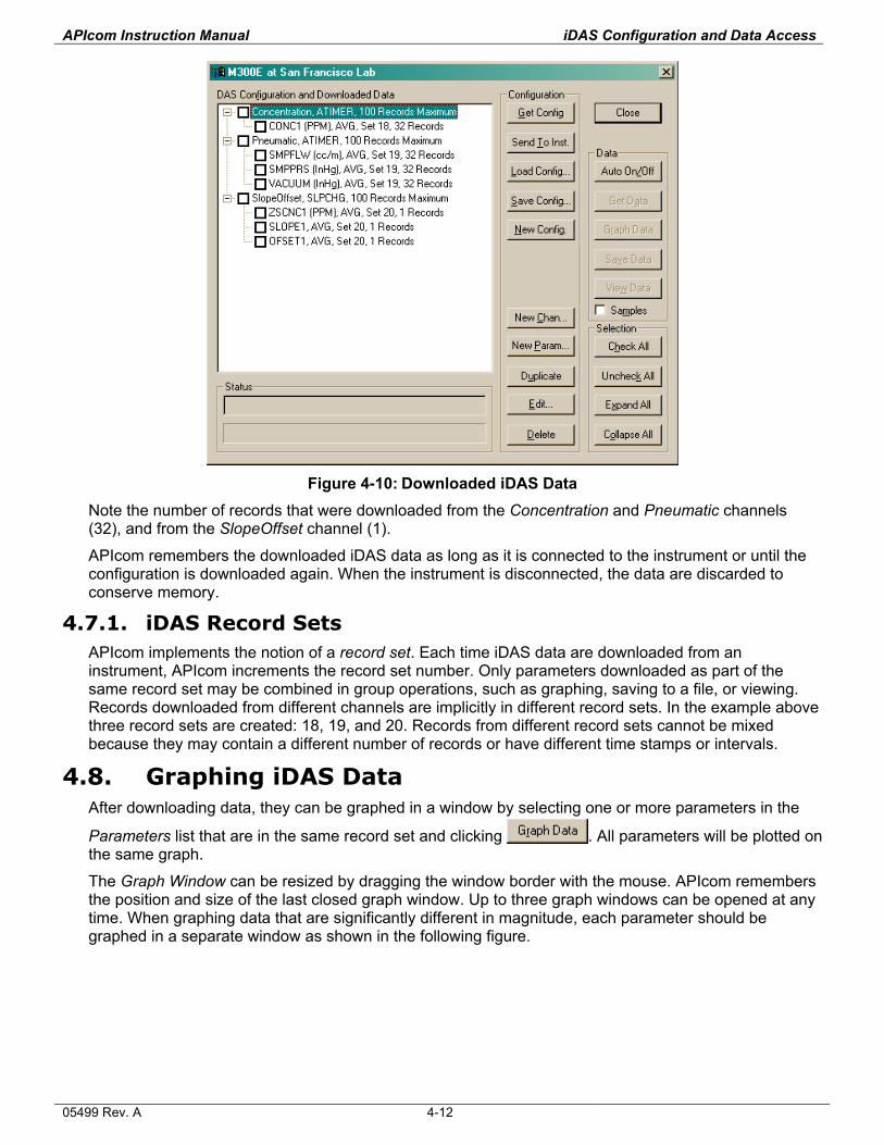
APIcom Instruction Manual iDAS Configuration and Data Access
Figure 4-10: Downloaded iDAS Data
Note the number of records that were downloaded from the Concentration and Pneumatic channels (32), and from the SlopeOffset channel (1).
APIcom remembers the downloaded iDAS data as long as it is connected to the instrument or until the configuration is downloaded again. When the instrument is disconnected, the data are discarded to conserve memory.
4.7.1. iDAS Record Sets APIcom implements the notion of a record set. Each time iDAS data are downloaded from an instrument, APIcom increments the record set number. Only parameters downloaded as part of the same record set may be combined in group operations, such as graphing, saving to a file, or viewing. Records downloaded from different channels are implicitly in different record sets. In the example above three record sets are created: 18, 19, and 20. Records from different record sets cannot be mixed because they may contain a different number of records or have different time stamps or intervals.
4.8. Graphing iDAS Data After downloading data, they can be graphed in a window by selecting one or more parameters in the
Parameters list that are in the same record set and clicking . All parameters will be plotted on the same graph.
The Graph Window can be resized by dragging the window border with the mouse. APIcom remembers the position and size of the last closed graph window. Up to three graph windows can be opened at any time. When graphing data that are significantly different in magnitude, each parameter should be graphed in a separate window as shown in the following figure.
05499 Rev. A 4-12
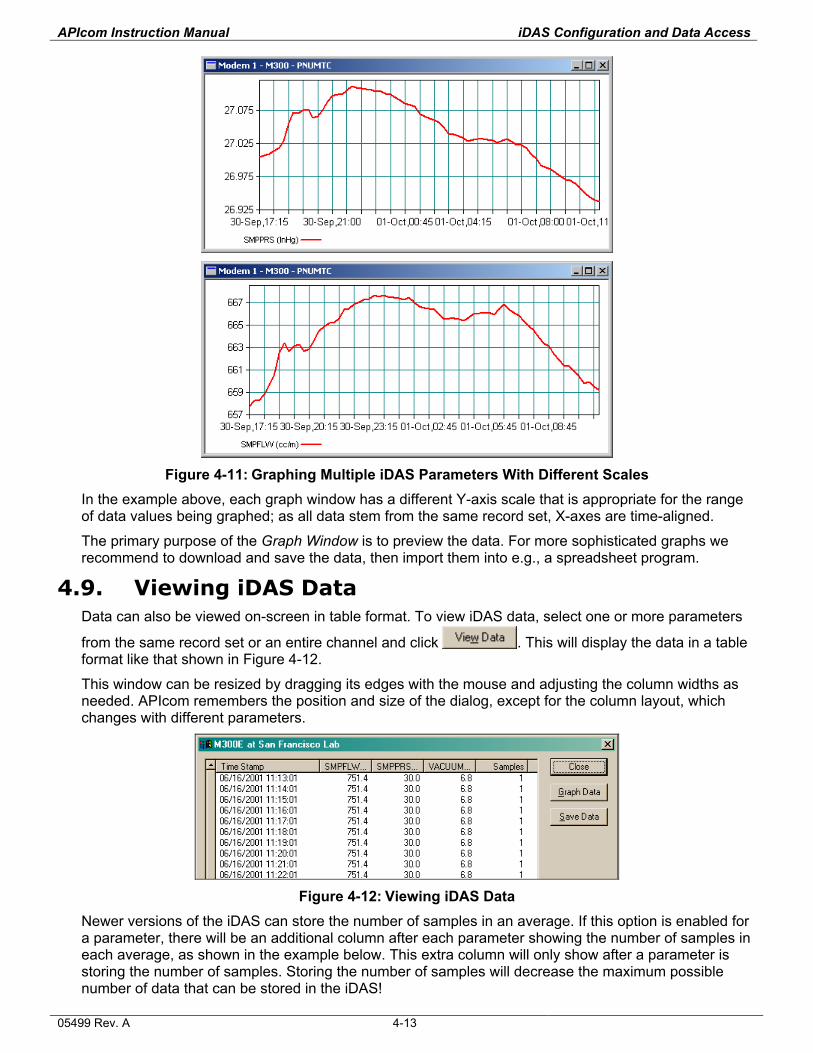
APIcom Instruction Manual iDAS Configuration and Data Access
Figure 4-11: Graphing Multiple iDAS Parameters With Different Scales
In the example above, each graph window has a different Y-axis scale that is appropriate for the range of data values being graphed; as all data stem from the same record set, X-axes are time-aligned.
The primary purpose of the Graph Window is to preview the data. For more sophisticated graphs we recommend to download and save the data, then import them into e.g., a spreadsheet program.
4.9. Viewing iDAS Data Data can also be viewed on-screen in table format. To view iDAS data, select one or more parameters
from the same record set or an entire channel and click . This will display the data in a table format like that shown in Figure 4-12.
This window can be resized by dragging its edges with the mouse and adjusting the column widths as needed. APIcom remembers the position and size of the dialog, except for the column layout, which changes with different parameters.
Figure 4-12: Viewing iDAS Data
Newer versions of the iDAS can store the number of samples in an average. If this option is enabled for a parameter, there will be an additional column after each parameter showing the number of samples in each average, as shown in the example below. This extra column will only show after a parameter is storing the number of samples. Storing the number of samples will decrease the maximum possible number of data that can be stored in the iDAS!
05499 Rev. A 4-13
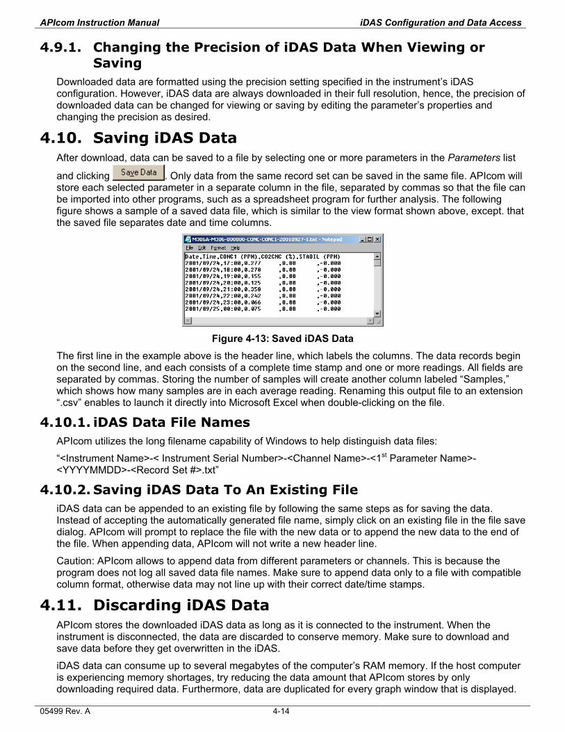
APIcom Instruction Manual iDAS Configuration and Data Access
4.9.1. Changing the Precision of iDAS Data When Viewing or Saving
Downloaded data are formatted using the precision setting specified in the instrument’s iDAS configuration. However, iDAS data are always downloaded in their full resolution, hence, the precision of downloaded data can be changed for viewing or saving by editing the parameter’s properties and changing the precision as desired.
4.10. Saving iDAS Data After download, data can be saved to a file by selecting one or more parameters in the Parameters list
and clicking . Only data from the same record set can be saved in the same file. APIcom will store each selected parameter in a separate column in the file, separated by commas so that the file can be imported into other programs, such as a spreadsheet program for further analysis. The following figure shows a sample of a saved data file, which is similar to the view format shown above, except. that the saved file separates date and time columns.
Figure 4-13: Saved iDAS Data
The first line in the example above is the header line, which labels the columns. The data records begin on the second line, and each consists of a complete time stamp and one or more readings. All fields are separated by commas. Storing the number of samples will create another column labeled “Samples,” which shows how many samples are in each average reading. Renaming this output file to an extension “.csv” enables to launch it directly into Microsoft Excel when double-clicking on the file.
4.10.1. iDAS Data File Names APIcom utilizes the long filename capability of Windows to help distinguish data files:
“<Instrument Name>-< Instrument Serial Number>-<Channel Name>-<1st Parameter Name>-<YYYYMMDD>-<Record Set #>.txt”
4.10.2. Saving iDAS Data To An Existing File iDAS data can be appended to an existing file by following the same steps as for saving the data. Instead of accepting the automatically generated file name, simply click on an existing file in the file save dialog. APIcom will prompt to replace the file with the new data or to append the new data to the end of the file. When appending data, APIcom will not write a new header line.
Caution: APIcom allows to append data from different parameters or channels. This is because the program does not log all saved data file names. Make sure to append data only to a file with compatible column format, otherwise data may not line up with their correct date/time stamps.
4.11. Discarding iDAS Data APIcom stores the downloaded iDAS data as long as it is connected to the instrument. When the instrument is disconnected, the data are discarded to conserve memory. Make sure to download and save data before they get overwritten in the iDAS.
iDAS data can consume up to several megabytes of the computer’s RAM memory. If the host computer is experiencing memory shortages, try reducing the data amount that APIcom stores by only downloading required data. Furthermore, data are duplicated for every graph window that is displayed.
05499 Rev. A 4-14
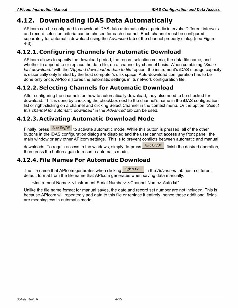
APIcom Instruction Manual iDAS Configuration and Data Access
4.12. Downloading iDAS Data Automatically APIcom can be configured to download iDAS data automatically at periodic intervals. Different intervals and record selection criteria can be chosen for each channel. Each channel must be configured separately for automatic download using the Advanced tab of the channel property dialog (see Figure 4-3).
4.12.1. Configuring Channels for Automatic Download APIcom allows to specify the download period, the record selection criteria, the data file name, and whether to append to or replace the data file, on a channel-by-channel basis. When combining "Since last download.” with the “Append downloaded data to file” option, the instrument’s iDAS storage capacity is essentially only limited by the host computer's disk space. Auto-download configuration has to be done only once, APIcom stores the automatic settings in its network configuration file.
4.12.2. Selecting Channels for Automatic Download After configuring the channels on how to automatically download, they also need to be checked for download. This is done by checking the checkbox next to the channel’s name in the iDAS configuration list or right-clicking on a channel and clicking Select Channel in the context menu. Or the option “Select this channel for automatic download” in the Advanced tab can be used.
4.12.3. Activating Automatic Download Mode
Finally, press to activate automatic mode. While this button is pressed, all of the other buttons in the iDAS configuration dialog are disabled and the user cannot access any front panel, the main window or any other APIcom settings. This is to prevent conflicts between automatic and manual
downloads. To regain access to the windows, simply de-press , finish the desired operation, then press the button again to resume automatic mode.
4.12.4. File Names For Automatic Download
The file name that APIcom generates when clicking in the Advanced tab has a different default format from the file name that APIcom generates when saving data manually:
“<Instrument Name>-< Instrument Serial Number>-<Channel Name>-Auto.txt”
Unlike the file name format for manual saves, the date and record set number are not included. This is because APIcom will repeatedly add data to this file or replace it entirely, hence those additional fields are meaningless in automatic mode.
05499 Rev. A 4-15

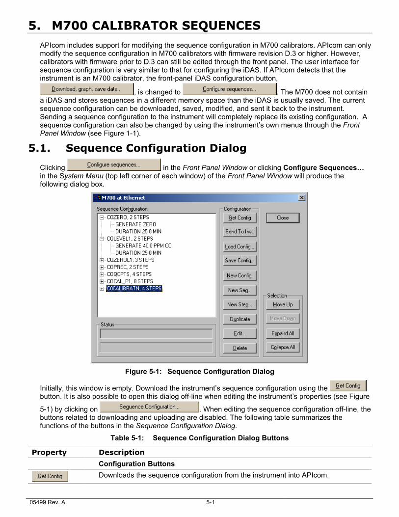
5. M700 CALIBRATOR SEQUENCES
APIcom includes support for modifying the sequence configuration in M700 calibrators. APIcom can only modify the sequence configuration in M700 calibrators with firmware revision D.3 or higher. However, calibrators with firmware prior to D.3 can still be edited through the front panel. The user interface for sequence configuration is very similar to that for configuring the iDAS. If APIcom detects that the instrument is an M700 calibrator, the front-panel iDAS configuration button,
, is changed to . The M700 does not contain a iDAS and stores sequences in a different memory space than the iDAS is usually saved. The current sequence configuration can be downloaded, saved, modified, and sent it back to the instrument. Sending a sequence configuration to the instrument will completely replace its existing configuration. A sequence configuration can also be changed by using the instrument’s own menus through the Front Panel Window (see Figure 1-1).
5.1. Sequence Configuration Dialog
Clicking in the Front Panel Window or clicking Configure Sequences… in the System Menu (top left corner of each window) of the Front Panel Window will produce the following dialog box.
Figure 5-1: Sequence Configuration Dialog
Initially, this window is empty. Download the instrument’s sequence configuration using the button. It is also possible to open this dialog off-line when editing the instrument’s properties (see Figure
5-1) by clicking on . When editing the sequence configuration off-line, the buttons related to downloading and uploading are disabled. The following table summarizes the functions of the buttons in the Sequence Configuration Dialog.
Table 5-1: Sequence Configuration Dialog Buttons
Property Description
Configuration Buttons
Downloads the sequence configuration from the instrument into APIcom.
05499 Rev. A 5-1
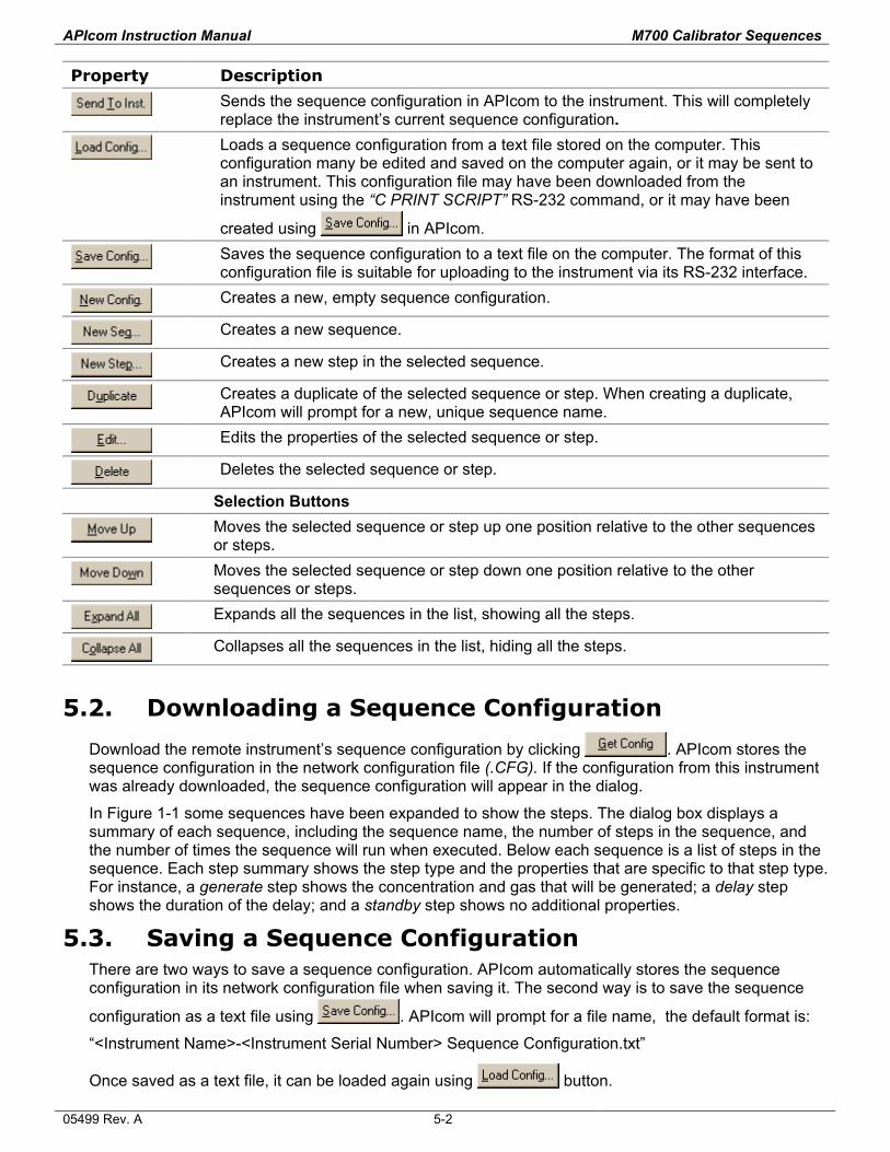
APIcom Instruction Manual M700 Calibrator Sequences
Property Description
Sends the sequence configuration in APIcom to the instrument. This will completely replace the instrument’s current sequence configuration.
Loads a sequence configuration from a text file stored on the computer. This configuration many be edited and saved on the computer again, or it may be sent to an instrument. This configuration file may have been downloaded from the instrument using the “C PRINT SCRIPT” RS-232 command, or it may have been
created using in APIcom.
Saves the sequence configuration to a text file on the computer. The format of this configuration file is suitable for uploading to the instrument via its RS-232 interface.
Creates a new, empty sequence configuration.
Creates a new sequence.
Creates a new step in the selected sequence.
Creates a duplicate of the selected sequence or step. When creating a duplicate, APIcom will prompt for a new, unique sequence name.
Edits the properties of the selected sequence or step.
Deletes the selected sequence or step.
Selection Buttons
Moves the selected sequence or step up one position relative to the other sequences or steps.
Moves the selected sequence or step down one position relative to the other sequences or steps.
Expands all the sequences in the list, showing all the steps.
Collapses all the sequences in the list, hiding all the steps.
5.2. Downloading a Sequence Configuration
Download the remote instrument’s sequence configuration by clicking . APIcom stores the sequence configuration in the network configuration file (.CFG). If the configuration from this instrument was already downloaded, the sequence configuration will appear in the dialog.
In Figure 1-1 some sequences have been expanded to show the steps. The dialog box displays a summary of each sequence, including the sequence name, the number of steps in the sequence, and the number of times the sequence will run when executed. Below each sequence is a list of steps in the sequence. Each step summary shows the step type and the properties that are specific to that step type. For instance, a generate step shows the concentration and gas that will be generated; a delay step shows the duration of the delay; and a standby step shows no additional properties.
5.3. Saving a Sequence Configuration There are two ways to save a sequence configuration. APIcom automatically stores the sequence configuration in its network configuration file when saving it. The second way is to save the sequence
configuration as a text file using . APIcom will prompt for a file name, the default format is:
“<Instrument Name>-<Instrument Serial Number> Sequence Configuration.txt”
Once saved as a text file, it can be loaded again using button.
05499 Rev. A 5-2
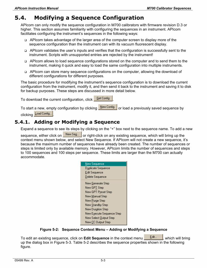
APIcom Instruction Manual M700 Calibrator Sequences
5.4. Modifying a Sequence Configuration APIcom can only modify the sequence configuration in M700 calibrators with firmware revision D.3 or higher. This section assumes familiarity with configuring the sequences in an instrument. APIcom facilitates configuring the instrument’s sequences in the following ways:
APIcom takes advantage of the larger area of the computer screen to display more of the sequence configuration than the instrument can with its vacuum fluorescent display.
APIcom validates the user’s inputs and verifies that the configuration is successfully sent to the instrument. Scripts with unsupported entries are rejected by the instrument!
APIcom allows to load sequence configurations stored on the computer and to send them to the instrument, making it quick and easy to load the same configuration into multiple instruments.
APIcom can store many sequence configurations on the computer, allowing the download of different configurations for different purposes.
The basic procedure for modifying the instrument’s sequence configuration is to download the current configuration from the instrument, modify it, and then send it back to the instrument and saving it to disk for backup purposes. These steps are discussed in more detail below.
To download the current configuration, click .
To start a new, empty configuration by clicking or load a previously saved sequence by
clicking .
5.4.1. Adding or Modifying a Sequence Expand a sequence to see its steps by clicking on the “+” box next to the sequence name. To add a new
sequence, either click on or right-click on any existing sequence, which will bring up the context menu shown below, and select New Sequence. If APIcom will not create a new sequence, it’s because the maximum number of sequences have already been created. The number of sequences or steps is limited only by available memory. However, APIcom limits the number of sequences and steps to 100 sequences and 100 steps per sequence. These limits are larger than the M700 can actually accommodate.
Figure 5-2: Sequence Context Menu – Adding or Modifying a Sequence
To edit an existing sequence, click on Edit Sequence in the context menu , which will bring up the dialog box in Figure 5-3. Table 5-2 describes the sequence properties shown in the following figure.
05499 Rev. A 5-3
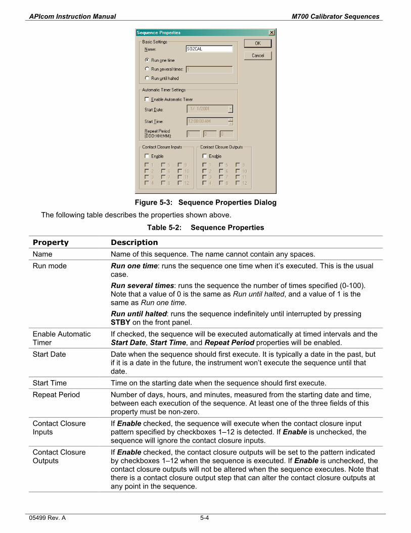
APIcom Instruction Manual M700 Calibrator Sequences
Figure 5-3: Sequence Properties Dialog
The following table describes the properties shown above.
Table 5-2: Sequence Properties
Property Description
Name Name of this sequence. The name cannot contain any spaces. Run mode Run one time: runs the sequence one time when it’s executed. This is the usual
case. Run several times: runs the sequence the number of times specified (0-100). Note that a value of 0 is the same as Run until halted, and a value of 1 is the same as Run one time. Run until halted: runs the sequence indefinitely until interrupted by pressing STBY on the front panel.
Enable Automatic Timer
If checked, the sequence will be executed automatically at timed intervals and the Start Date, Start Time, and Repeat Period properties will be enabled.
Start Date Date when the sequence should first execute. It is typically a date in the past, but if it is a date in the future, the instrument won’t execute the sequence until that date.
Start Time Time on the starting date when the sequence should first execute. Repeat Period Number of days, hours, and minutes, measured from the starting date and time,
between each execution of the sequence. At least one of the three fields of this property must be non-zero.
Contact Closure Inputs
If Enable checked, the sequence will execute when the contact closure input pattern specified by checkboxes 1–12 is detected. If Enable is unchecked, the sequence will ignore the contact closure inputs.
Contact Closure Outputs
If Enable checked, the contact closure outputs will be set to the pattern indicated by checkboxes 1–12 when the sequence is executed. If Enable is unchecked, the contact closure outputs will not be altered when the sequence executes. Note that there is a contact closure output step that can alter the contact closure outputs at any point in the sequence.
05499 Rev. A 5-4
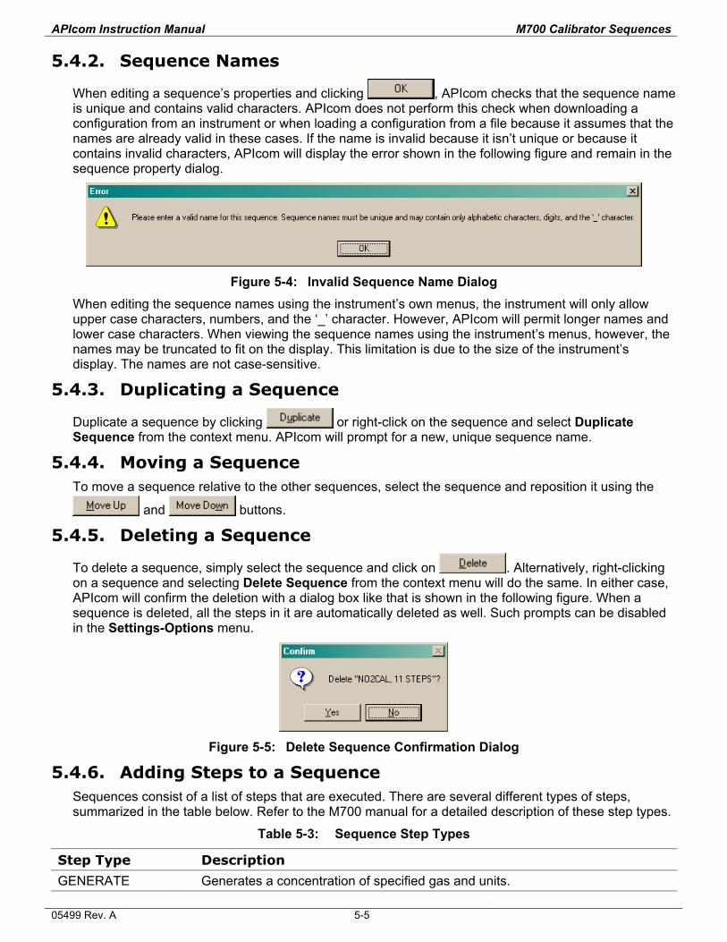
APIcom Instruction Manual M700 Calibrator Sequences
5.4.2. Sequence Names
When editing a sequence’s properties and clicking , APIcom checks that the sequence name is unique and contains valid characters. APIcom does not perform this check when downloading a configuration from an instrument or when loading a configuration from a file because it assumes that the names are already valid in these cases. If the name is invalid because it isn’t unique or because it contains invalid characters, APIcom will display the error shown in the following figure and remain in the sequence property dialog.
Figure 5-4: Invalid Sequence Name Dialog
When editing the sequence names using the instrument’s own menus, the instrument will only allow upper case characters, numbers, and the ‘_’ character. However, APIcom will permit longer names and lower case characters. When viewing the sequence names using the instrument’s menus, however, the names may be truncated to fit on the display. This limitation is due to the size of the instrument’s display. The names are not case-sensitive.
5.4.3. Duplicating a Sequence
Duplicate a sequence by clicking or right-click on the sequence and select Duplicate Sequence from the context menu. APIcom will prompt for a new, unique sequence name.
5.4.4. Moving a Sequence To move a sequence relative to the other sequences, select the sequence and reposition it using the
and buttons.
5.4.5. Deleting a Sequence
To delete a sequence, simply select the sequence and click on . Alternatively, right-clicking on a sequence and selecting Delete Sequence from the context menu will do the same. In either case, APIcom will confirm the deletion with a dialog box like that is shown in the following figure. When a sequence is deleted, all the steps in it are automatically deleted as well. Such prompts can be disabled in the Settings-Options menu.
Figure 5-5: Delete Sequence Confirmation Dialog
5.4.6. Adding Steps to a Sequence Sequences consist of a list of steps that are executed. There are several different types of steps, summarized in the table below. Refer to the M700 manual for a detailed description of these step types.
Table 5-3: Sequence Step Types
Step Type Description
GENERATE Generates a concentration of specified gas and units.
05499 Rev. A 5-5
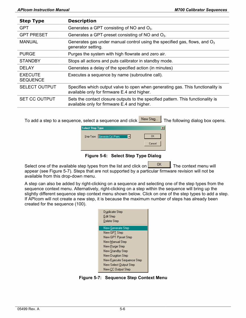
APIcom Instruction Manual M700 Calibrator Sequences
Step Type Description
GPT Generates a GPT consisting of NO and O3. GPT PRESET Generates a GPT-preset consisting of NO and O3. MANUAL Generates gas under manual control using the specified gas, flows, and O3
generator setting. PURGE Purges the system with high flowrate and zero air. STANDBY Stops all actions and puts calibrator in standby mode. DELAY Generates a delay of the specified action (in minutes) EXECUTE SEQUENCE
Executes a sequence by name (subroutine call).
SELECT OUTPUT Specifies which output valve to open when generating gas. This functionality is available only for firmware E.4 and higher.
SET CC OUTPUT Sets the contact closure outputs to the specified pattern. This functionality is available only for firmware E.4 and higher.
To add a step to a sequence, select a sequence and click . The following dialog box opens.
Figure 5-6: Select Step Type Dialog
Select one of the available step types from the list and click on . The context menu will appear (see Figure 5-7). Steps that are not supported by a particular firmware revision will not be available from this drop-down menu.
A step can also be added by right-clicking on a sequence and selecting one of the step types from the sequence context menu. Alternatively, right-clicking on a step within the sequence will bring up the slightly different sequence step context menu shown below. Click on one of the step types to add a step. If APIcom will not create a new step, it is because the maximum number of steps has already been created for the sequence (100).
Figure 5-7: Sequence Step Context Menu
05499 Rev. A 5-6
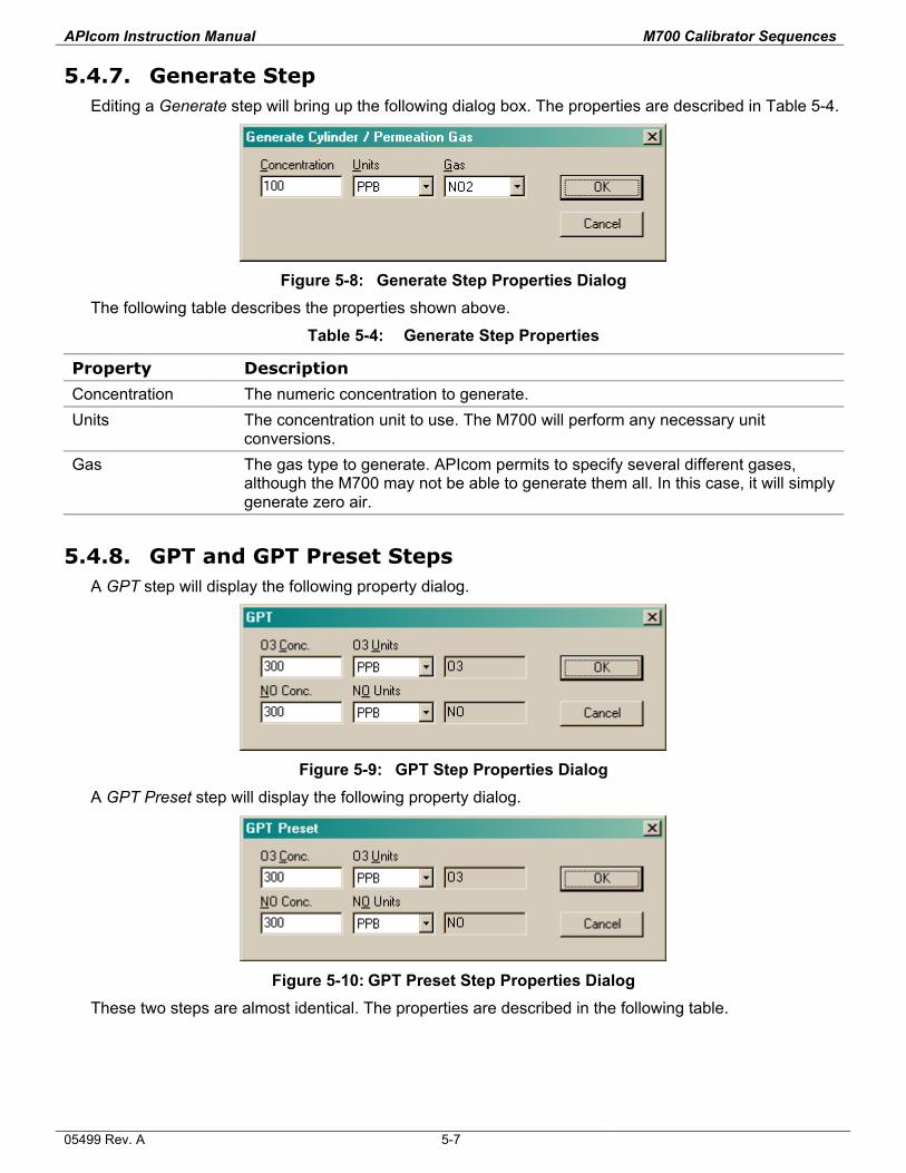
APIcom Instruction Manual M700 Calibrator Sequences
5.4.7. Generate Step Editing a Generate step will bring up the following dialog box. The properties are described in Table 5-4.
Figure 5-8: Generate Step Properties Dialog
The following table describes the properties shown above.
Table 5-4: Generate Step Properties
Property Description
Concentration The numeric concentration to generate. Units The concentration unit to use. The M700 will perform any necessary unit
conversions. Gas The gas type to generate. APIcom permits to specify several different gases,
although the M700 may not be able to generate them all. In this case, it will simply generate zero air.
5.4.8. GPT and GPT Preset Steps A GPT step will display the following property dialog.
Figure 5-9: GPT Step Properties Dialog
A GPT Preset step will display the following property dialog.
Figure 5-10: GPT Preset Step Properties Dialog
These two steps are almost identical. The properties are described in the following table.
05499 Rev. A 5-7
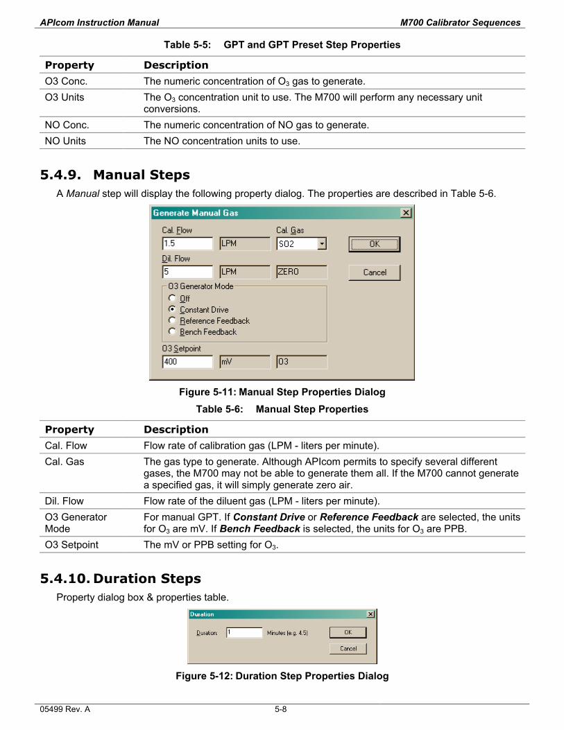
APIcom Instruction Manual M700 Calibrator Sequences
Table 5-5: GPT and GPT Preset Step Properties
Property Description
O3 Conc. The numeric concentration of O3 gas to generate. O3 Units The O3 concentration unit to use. The M700 will perform any necessary unit
conversions. NO Conc. The numeric concentration of NO gas to generate. NO Units The NO concentration units to use.
5.4.9. Manual Steps A Manual step will display the following property dialog. The properties are described in Table 5-6.
Figure 5-11: Manual Step Properties Dialog
Table 5-6: Manual Step Properties
Property Description
Cal. Flow Flow rate of calibration gas (LPM - liters per minute). Cal. Gas The gas type to generate. Although APIcom permits to specify several different
gases, the M700 may not be able to generate them all. If the M700 cannot generate a specified gas, it will simply generate zero air.
Dil. Flow Flow rate of the diluent gas (LPM - liters per minute). O3 Generator Mode
For manual GPT. If Constant Drive or Reference Feedback are selected, the units for O3 are mV. If Bench Feedback is selected, the units for O3 are PPB.
O3 Setpoint The mV or PPB setting for O3.
5.4.10. Duration Steps Property dialog box & properties table.
Figure 5-12: Duration Step Properties Dialog
05499 Rev. A 5-8
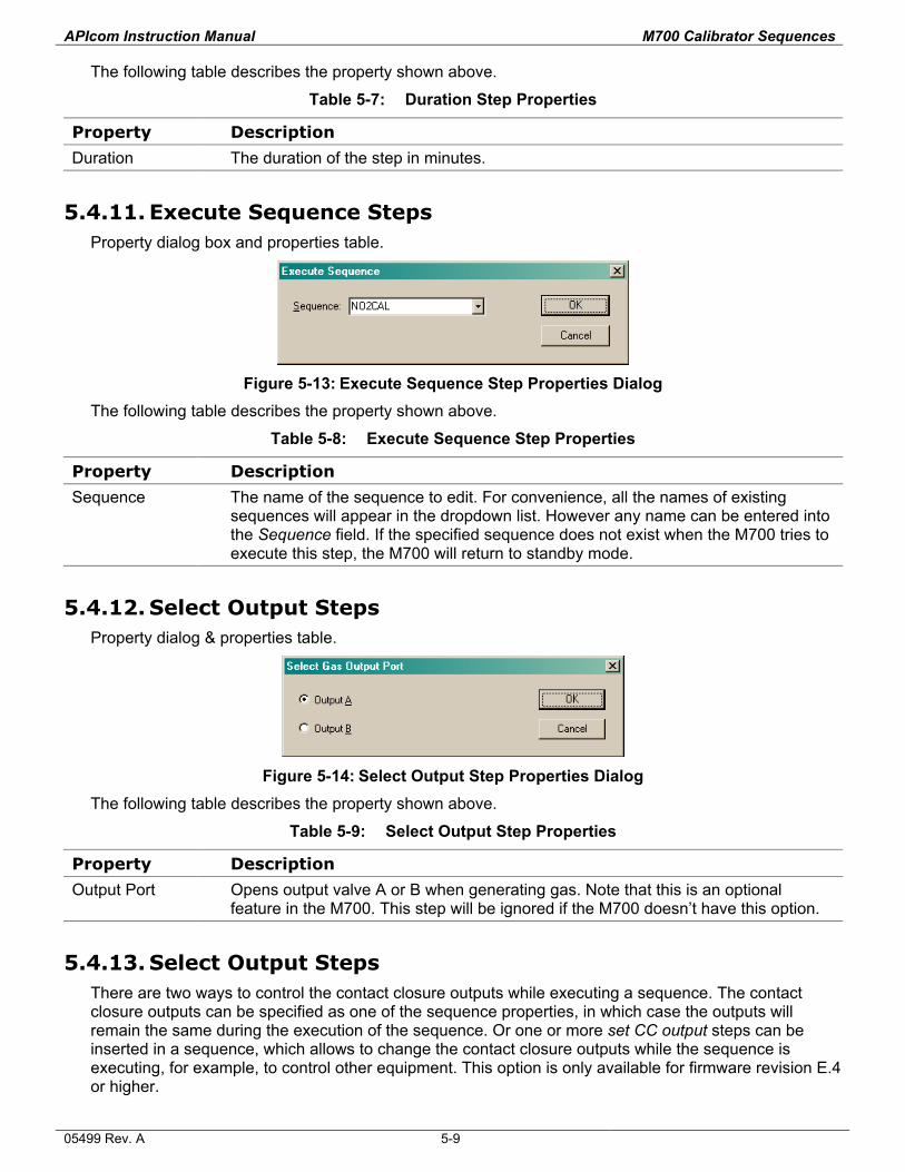
APIcom Instruction Manual M700 Calibrator Sequences
The following table describes the property shown above.
Table 5-7: Duration Step Properties
Property Description
Duration The duration of the step in minutes.
5.4.11. Execute Sequence Steps Property dialog box and properties table.
Figure 5-13: Execute Sequence Step Properties Dialog
The following table describes the property shown above.
Table 5-8: Execute Sequence Step Properties
Property Description
Sequence The name of the sequence to edit. For convenience, all the names of existing sequences will appear in the dropdown list. However any name can be entered into the Sequence field. If the specified sequence does not exist when the M700 tries to execute this step, the M700 will return to standby mode.
5.4.12. Select Output Steps Property dialog & properties table.
Figure 5-14: Select Output Step Properties Dialog
The following table describes the property shown above.
Table 5-9: Select Output Step Properties
Property Description
Output Port Opens output valve A or B when generating gas. Note that this is an optional feature in the M700. This step will be ignored if the M700 doesn’t have this option.
5.4.13. Select Output Steps There are two ways to control the contact closure outputs while executing a sequence. The contact closure outputs can be specified as one of the sequence properties, in which case the outputs will remain the same during the execution of the sequence. Or one or more set CC output steps can be inserted in a sequence, which allows to change the contact closure outputs while the sequence is executing, for example, to control other equipment. This option is only available for firmware revision E.4 or higher.
05499 Rev. A 5-9
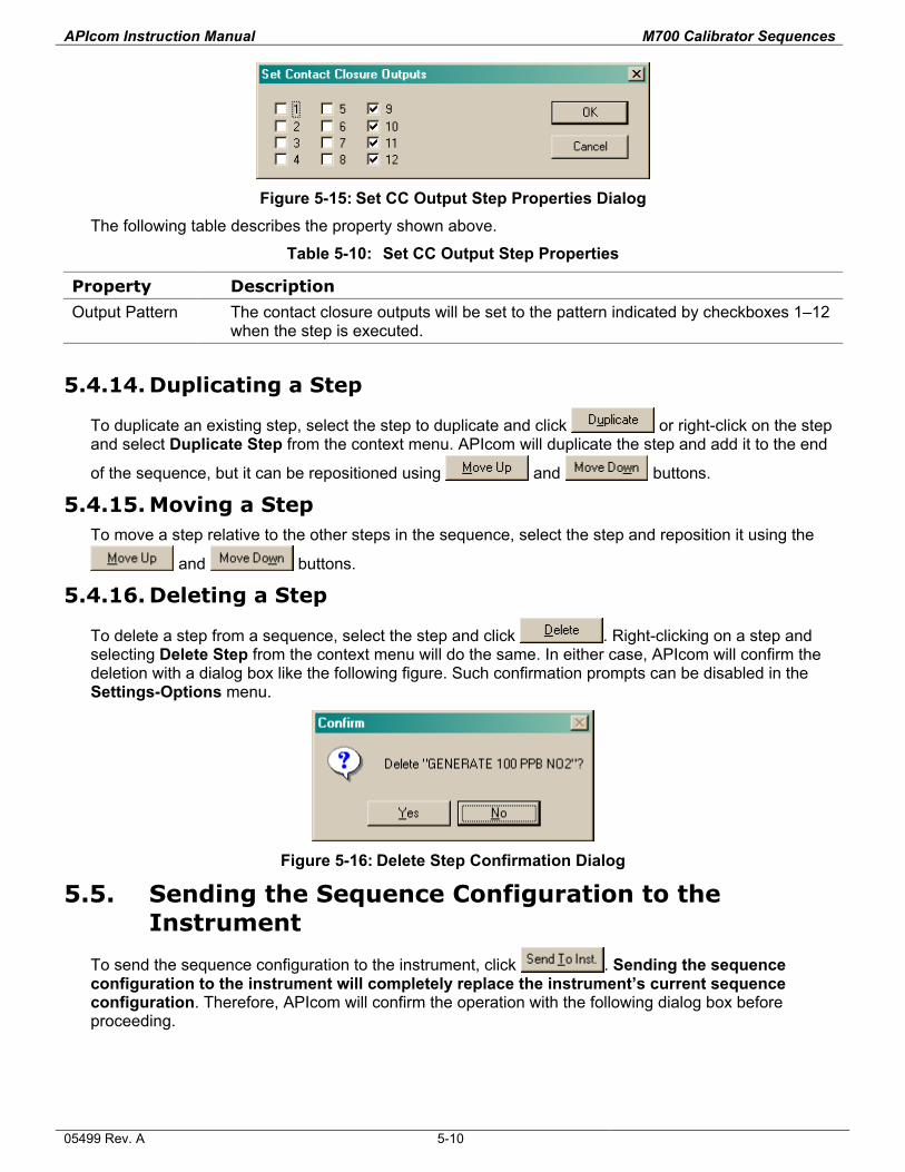
APIcom Instruction Manual M700 Calibrator Sequences
Figure 5-15: Set CC Output Step Properties Dialog
The following table describes the property shown above.
Table 5-10: Set CC Output Step Properties
Property Description
Output Pattern The contact closure outputs will be set to the pattern indicated by checkboxes 1–12 when the step is executed.
5.4.14. Duplicating a Step
To duplicate an existing step, select the step to duplicate and click or right-click on the step and select Duplicate Step from the context menu. APIcom will duplicate the step and add it to the end
of the sequence, but it can be repositioned using and buttons.
5.4.15. Moving a Step To move a step relative to the other steps in the sequence, select the step and reposition it using the
and buttons.
5.4.16. Deleting a Step
To delete a step from a sequence, select the step and click . Right-clicking on a step and selecting Delete Step from the context menu will do the same. In either case, APIcom will confirm the deletion with a dialog box like the following figure. Such confirmation prompts can be disabled in the Settings-Options menu.
Figure 5-16: Delete Step Confirmation Dialog
5.5. Sending the Sequence Configuration to the Instrument
To send the sequence configuration to the instrument, click . Sending the sequence configuration to the instrument will completely replace the instrument’s current sequence configuration. Therefore, APIcom will confirm the operation with the following dialog box before proceeding.
05499 Rev. A 5-10
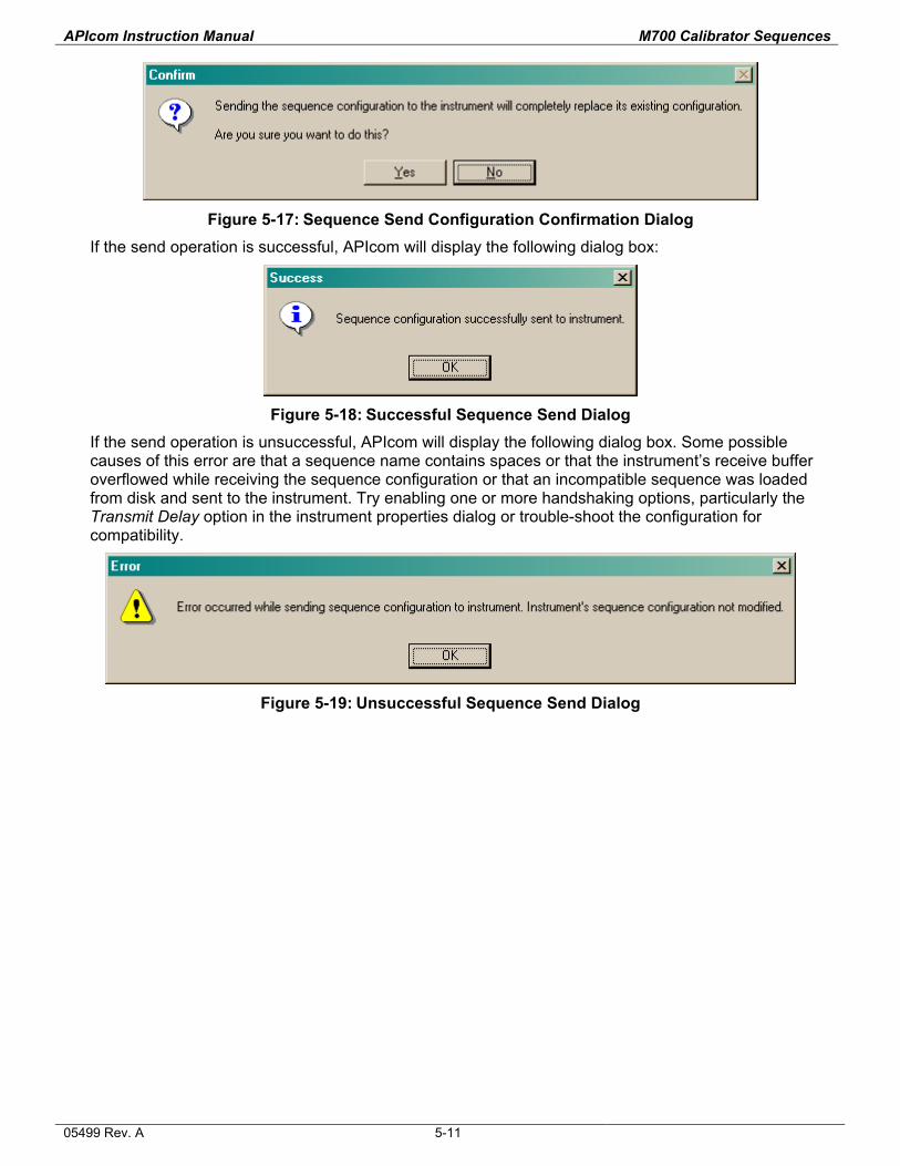
APIcom Instruction Manual M700 Calibrator Sequences
Figure 5-17: Sequence Send Configuration Confirmation Dialog
If the send operation is successful, APIcom will display the following dialog box:
Figure 5-18: Successful Sequence Send Dialog
If the send operation is unsuccessful, APIcom will display the following dialog box. Some possible causes of this error are that a sequence name contains spaces or that the instrument’s receive buffer overflowed while receiving the sequence configuration or that an incompatible sequence was loaded from disk and sent to the instrument. Try enabling one or more handshaking options, particularly the Transmit Delay option in the instrument properties dialog or trouble-shoot the configuration for compatibility.
Figure 5-19: Unsuccessful Sequence Send Dialog
05499 Rev. A 5-11

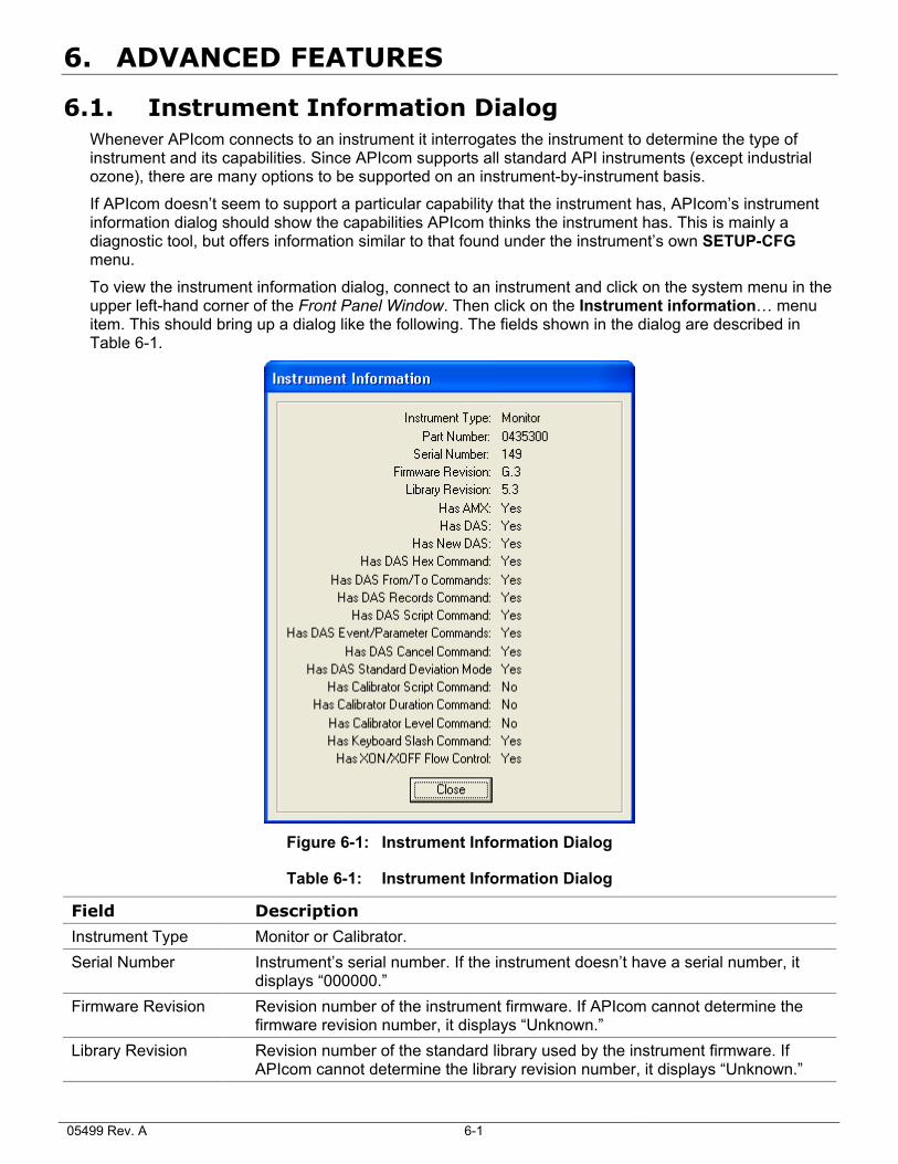
6. ADVANCED FEATURES
6.1. Instrument Information Dialog Whenever APIcom connects to an instrument it interrogates the instrument to determine the type of instrument and its capabilities. Since APIcom supports all standard API instruments (except industrial ozone), there are many options to be supported on an instrument-by-instrument basis.
If APIcom doesn’t seem to support a particular capability that the instrument has, APIcom’s instrument information dialog should show the capabilities APIcom thinks the instrument has. This is mainly a diagnostic tool, but offers information similar to that found under the instrument’s own SETUP-CFG menu.
To view the instrument information dialog, connect to an instrument and click on the system menu in the upper left-hand corner of the Front Panel Window. Then click on the Instrument information… menu item. This should bring up a dialog like the following. The fields shown in the dialog are described in Table 6-1.
Figure 6-1: Instrument Information Dialog
Table 6-1: Instrument Information Dialog
Field Description
Instrument Type Monitor or Calibrator. Serial Number Instrument’s serial number. If the instrument doesn’t have a serial number, it
displays “000000.” Firmware Revision Revision number of the instrument firmware. If APIcom cannot determine the
firmware revision number, it displays “Unknown.” Library Revision Revision number of the standard library used by the instrument firmware. If
APIcom cannot determine the library revision number, it displays “Unknown.”
05499 Rev. A 6-1
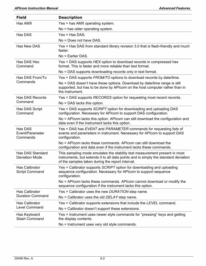
APIcom Instruction Manual Advanced Features
Field Description
Has AMX Yes = has AMX operating system. No = has older operating system.
Has DAS Yes = Has DAS. No = Does not have DAS.
Has New DAS Yes = Has DAS from standard library revision 3.0 that is flash-friendly and much faster. No = Earlier DAS.
Has DAS Hex Command
Yes = DAS supports HEX option to download records in compressed hex format. This is faster and more reliable than text format. No = DAS supports downloading records only in text format.
Has DAS From/To Commands
Yes = DAS supports FROM/TO options to download records by date/time. No = DAS doesn’t have these options. Download by date/time range is still supported, but has to be done by APIcom on the host computer rather than in the instrument.
Has DAS Records Command
Yes = DAS supports RECORDS option for requesting most recent records. No = DAS lacks this option.
Has DAS Script Command
Yes = DAS supports SCRIPT option for downloading and uploading DAS configuration. Necessary for APIcom to support DAS configuration. No = APIcom lacks this option. APIcom can still download the configuration and data even if the instrument lacks this option.
Has DAS Event/Parameter Commands
Yes = DAS has EVENT and PARAMETER commands for requesting lists of events and parameters in instrument. Necessary for APIcom to support DAS configuration. No = APIcom lacks these commands. APIcom can still download the configuration and data even if the instrument lacks these commands.
Has DAS Standard Deviation Mode
This sampling mode emulates the stability test measurement present in most instruments, but extends it to all data points and is simply the standard deviation of the samples taken during the report interval.
Has Calibrator Script Command
Yes = Calibrator supports SCRIPT option for downloading and uploading sequence configuration. Necessary for APIcom to support sequence configuration. No = APIcom lacks these commands. APIcom cannot download or modify the sequence configuration if the instrument lacks this option.
Has Calibrator Duration Command
Yes = Calibrator uses the new DURATION step name. No = Calibrator uses the old DELAY step name.
Has Calibrator Level Command
Yes = Calibrator supports extensions that include the LEVEL command. No = Calibrator doesn’t support these extensions.
Has Keyboard Slash Command
Yes = Instrument uses newer style commands for “pressing” keys and getting the display contents. No = Instrument uses very old style commands.
05499 Rev. A 6-2
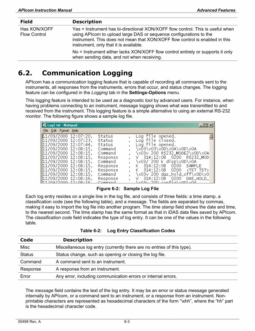
APIcom Instruction Manual Advanced Features
Field Description
Has XON/XOFF Flow Control
Yes = Instrument has bi-directional XON/XOFF flow control. This is useful when using APIcom to upload large DAS or sequence configurations to the instrument. This does not mean that XON/XOFF flow control is enabled in this instrument, only that it is available. No = Instrument either lacks XON/XOFF flow control entirely or supports it only when sending data, and not when receiving.
6.2. Communication Logging APIcom has a communication logging feature that is capable of recording all commands sent to the instruments, all responses from the instruments, errors that occur, and status changes. The logging feature can be configured in the Logging tab in the Settings-Options menu.
This logging feature is intended to be used as a diagnostic tool by advanced users. For instance, when having problems connecting to an instrument, message logging shows what was transmitted to and received from the instrument. This logging feature is a simple alternative to using an external RS-232 monitor. The following figure shows a sample log file.
Figure 6-2: Sample Log File
Each log entry resides on a single line in the log file, and consists of three fields: a time stamp, a classification code (see the following table), and a message. The fields are separated by commas, making it easy to import the log file into another program. The time stamp field shows the date and time, to the nearest second. The time stamp has the same format as that in iDAS data files saved by APIcom. The classification code field indicates the type of log entry. It can be one of the values in the following table.
Table 6-2: Log Entry Classification Codes
Code Description
Misc Miscellaneous log entry (currently there are no entries of this type). Status Status change, such as opening or closing the log file. Command A command sent to an instrument. Response A response from an instrument. Error Any error, including communication errors or internal errors.
The message field contains the text of the log entry. It may be an error or status message generated internally by APIcom, or a command sent to an instrument, or a response from an instrument. Non-printable characters are represented as hexadecimal characters of the form “\xhh”, where the “hh” part is the hexadecimal character code.
05499 Rev. A 6-3
APIcom Instruction Manual Advanced Features
Beware that the log files can get very large. For example, if automatic display updating at 5-second intervals is enabled, APIcom stores about 280 bytes per display update, per instrument in the log file. That works out to about 67.2 kbytes per hour, or about 1.6 MB per day, per instrument. Also, the log file is locked for access while APIcom is running.
Timeout errors will always appear in the log file. These are not necessarily errors, though they might be. In some cases, the APIcom can detect the end of a transmission of data from an instrument only by waiting for a timeout to occur. Rather than have APIcom determine whether a timeout is normal or an error, it is easier to record all timeouts as errors in the log file.
05499 Rev. A 6-4
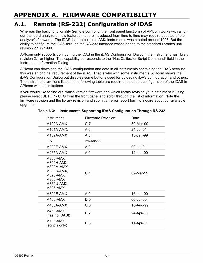
APPENDIX A. FIRMWARE COMPATIBILITY
A.1. Remote (RS-232) Configuration of iDAS Whereas the basic functionality (remote control of the front panel functions) of APIcom works with all of our standard analyzers, new features that are introduced from time to time may require updates of the analyzer's firmware. The iDAS feature built into AMX instruments was created around 1996. But the ability to configure the iDAS through the RS-232 interface wasn't added to the standard libraries until revision 2.1 in 1999.
APIcom only supports configuring the iDAS in the iDAS Configuration Dialog if the instrument has library revision 2.1 or higher. This capability corresponds to the "Has Calibrator Script Command" field in the Instrument Information Dialog.
APIcom can download the iDAS configuration and data in all instruments containing the iDAS because this was an original requirement of the iDAS. That is why with some instruments, APIcom shows the iDAS Configuration Dialog but disables some buttons used for uploading iDAS configuration and others. The instrument revisions listed in the following table are required to support configuration of the iDAS in APIcom without limitations.
If you would like to find out, which version firmware and which library revision your instrument is using, please select SETUP - CFG from the front panel and scroll through the list of information. Note the firmware revision and the library revision and submit an error report form to inquire about our available upgrades.
Table 6-3: Instruments Supporting iDAS Configuration Through RS-232
Instrument Firmware Revision Date M100A-AMX C.7 30-Mar-99 M101A-AMX, A.0 24-Jul-01 M102A-AMX A.8 15-Jan-99 E.5 29-Jan-99 M200E-AMX A.0 09-Jul-01 M265A-AMX A.0 12-Jan-00 M300-AMX, M300H-AMX, M300M-AMX, M300S-AMX, M320-AMX, M360-AMX, M360U-AMX, M306-AMX
C.1 02-Mar-99
M300E-AMX A.0 16-Jan-00 M400-AMX D.0 06-Jul-00 M400A-AMX C.0 18-Aug-99 M450-AMX (has no iDAS!) D.7 24-Apr-00
M700-AMX (scripts only) D.3 11-Apr-01
05499 Rev. A A-1
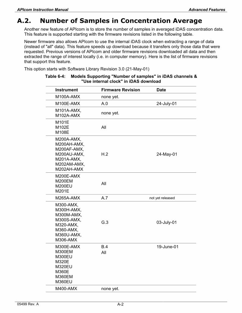
APIcom Instruction Manual Advanced Features
A.2. Number of Samples in Concentration Average Another new feature of APIcom is to store the number of samples in averaged iDAS concentration data. This feature is supported starting with the firmware revisions listed in the following table.
Newer firmware also allows APIcom to use the internal iDAS clock when extracting a range of data (instead of "all" data). This feature speeds up download because it transfers only those data that were requested. Previous versions of APIcom and older firmware revisions downloaded all data and then extracted the range of interest locally (i.e. in computer memory). Here is the list of firmware revisions that support this feature.
This option starts with Software Library Revision 3.0 (21-May-01)
Table 6-4: Models Supporting "Number of samples" in iDAS channels & "Use internal clock" in iDAS download
Instrument Firmware Revision Date M100A-AMX none yet. M100E-AMX A.0 24-July-01 M101A-AMX, M102A-AMX none yet.
M101E M102E M108E
All
M200A-AMX, M200AH-AMX, M200AF-AMX, M200AU-AMX, M201A-AMX, M202AM-AMX, M202AH-AMX
H.2 24-May-01
M200E-AMX M200EM M200EU M201E
All
M265A-AMX A.7 not yet released
M300-AMX, M300H-AMX, M300M-AMX, M300S-AMX, M320-AMX, M360-AMX, M360U-AMX, M306-AMX
G.3 03-July-01
M300E-AMX M300EM M300EU M320E M320EU M360E M360EM M360EU
B.4 All
19-June-01
M400-AMX none yet.
05499 Rev. A A-2
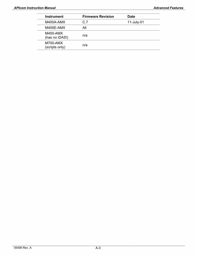
APIcom Instruction Manual Advanced Features
05499 Rev. A A-3
Instrument Firmware Revision Date M400A-AMX C.7 11-July-01 M400E-AMX All M450-AMX (has no iDAS!) n/a
M700-AMX (scripts only) n/a