techniques of mechanical measurements -...
TRANSCRIPT
Techniques of mechanical measurements f CERN A li ti d E i tfor CERN Applications and Environment
M. Guinchard, A. Kuzmin, EN-MME
Mechanical Measurement Lab, 2010.11.03EDMS no. 1064933
Outline
• Introduction
• Measurements with strain gauges
• Measurements with capacitive gaugesp g g
• Other Measurements• Other Measurements
• Conclusion
2Mechanical Measurement Lab [email protected]
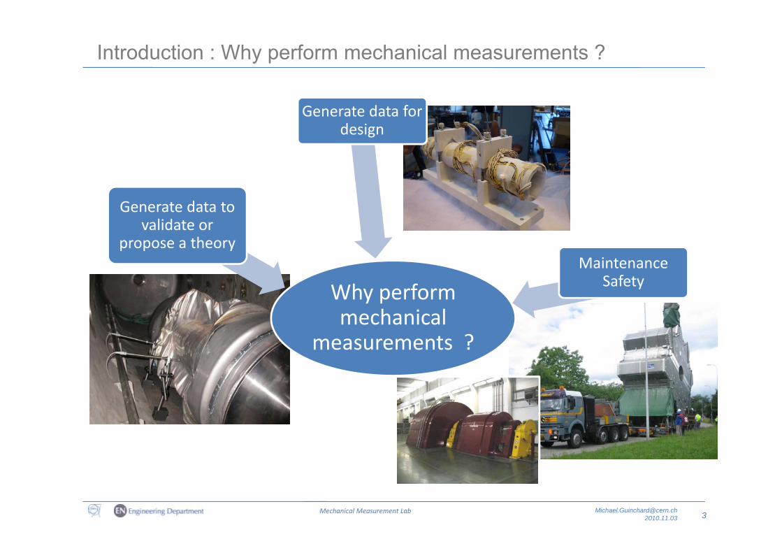
Introduction : Why perform mechanical measurements ?
Generate data for design
Generate data to validate or
propose a theoryMaintenance
S f tSafetyWhy perform mechanical
measurements ?measurements ?
3Mechanical Measurement Lab [email protected]
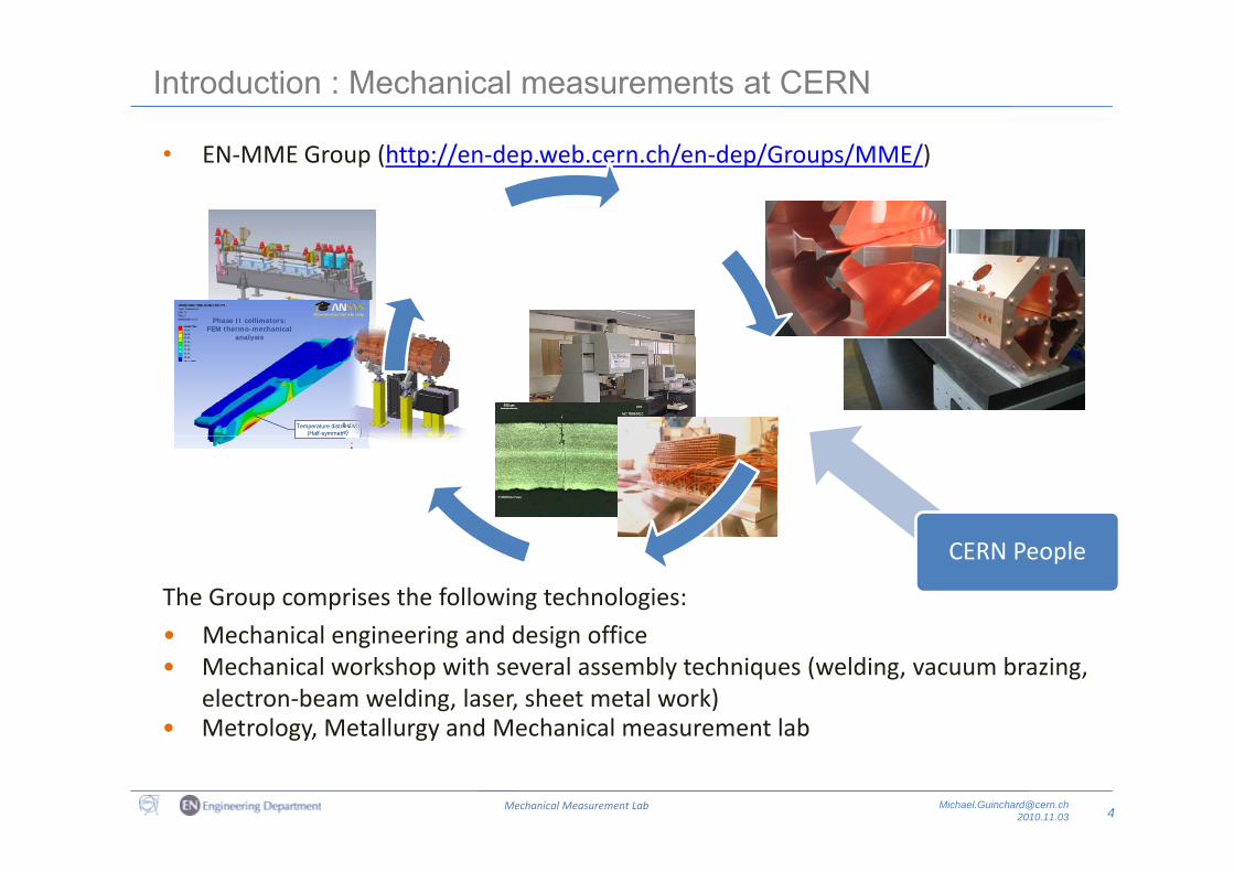
Introduction : Mechanical measurements at CERN
• EN‐MME Group (http://en‐dep.web.cern.ch/en‐dep/Groups/MME/)
ffPhase II collimators:
FEM thermo-mechanical analysis
f
Temperature distribution(Half-symmetry)
analysis
d
d( y y)
dCERN People
The Group comprises the following technologies:
• Mechanical engineering and design office• Mechanical engineering and design office • Mechanical workshop with several assembly techniques (welding, vacuum brazing,
electron‐beam welding, laser, sheet metal work)• Metrology Metallurgy and Mechanical measurement lab
4Mechanical Measurement Lab [email protected]
Metrology, Metallurgy and Mechanical measurement lab
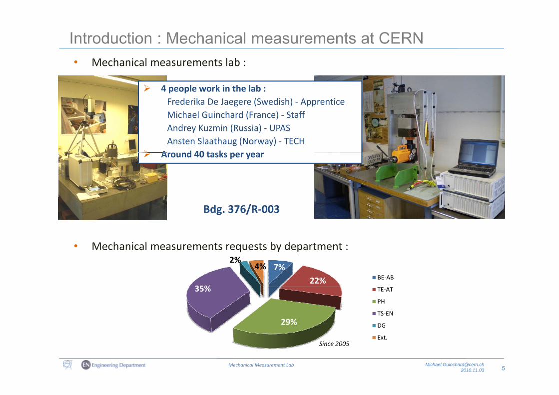
Introduction : Mechanical measurements at CERN• Mechanical measurements lab :• Mechanical measurements lab :
4 people work in the lab :Frederika De Jaegere (Swedish) ‐ ApprenticeMichael Guinchard (France) ‐ StaffAndrey Kuzmin (Russia) ‐ UPASAnsten Slaathaug (Norway) ‐ TECH
Around 40 tasks per year Around 40 tasks per year
M h i l b d
Bdg. 376/R‐003
• Mechanical measurements requests by department :
7%
22%35%
2%4%
BE‐AB
29%
35% TE‐AT
PH
TS‐EN
DG
5Mechanical Measurement Lab [email protected]
Ext.Since 2005
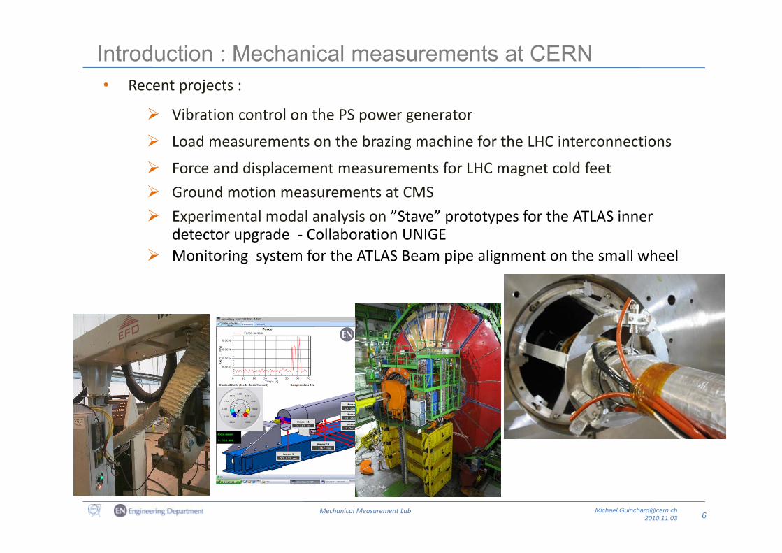
Introduction : Mechanical measurements at CERN• Recent projects :Recent projects :
Vibration control on the PS power generator
Load measurements on the brazing machine for the LHC interconnections
Force and displacement measurements for LHC magnet cold feet
Ground motion measurements at CMS
Experimental modal analysis on ”Stave” prototypes for the ATLAS inner Experimental modal analysis on ”Stave” prototypes for the ATLAS inner detector upgrade ‐ Collaboration UNIGE
Monitoring system for the ATLAS Beam pipe alignment on the small wheel
6Mechanical Measurement Lab [email protected]
Introduction : Mechanical measurements at CERN
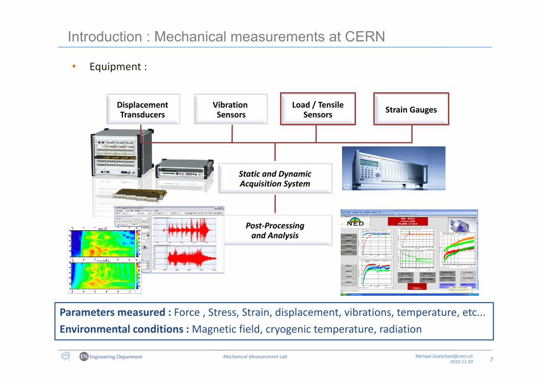
• Equipment :
Displacement Vibration Load / TensileDisplacement Transducers
VibrationSensors
Load / TensileSensors Strain Gauges
Static and DynamicAcquisition System
Post‐Processingand Analysisand Analysis
Parameters measured : Force , Stress, Strain, displacement, vibrations, temperature, etc...
7Mechanical Measurement Lab [email protected]
Environmental conditions : Magnetic field, cryogenic temperature, radiation
Introduction : Mechanical properties
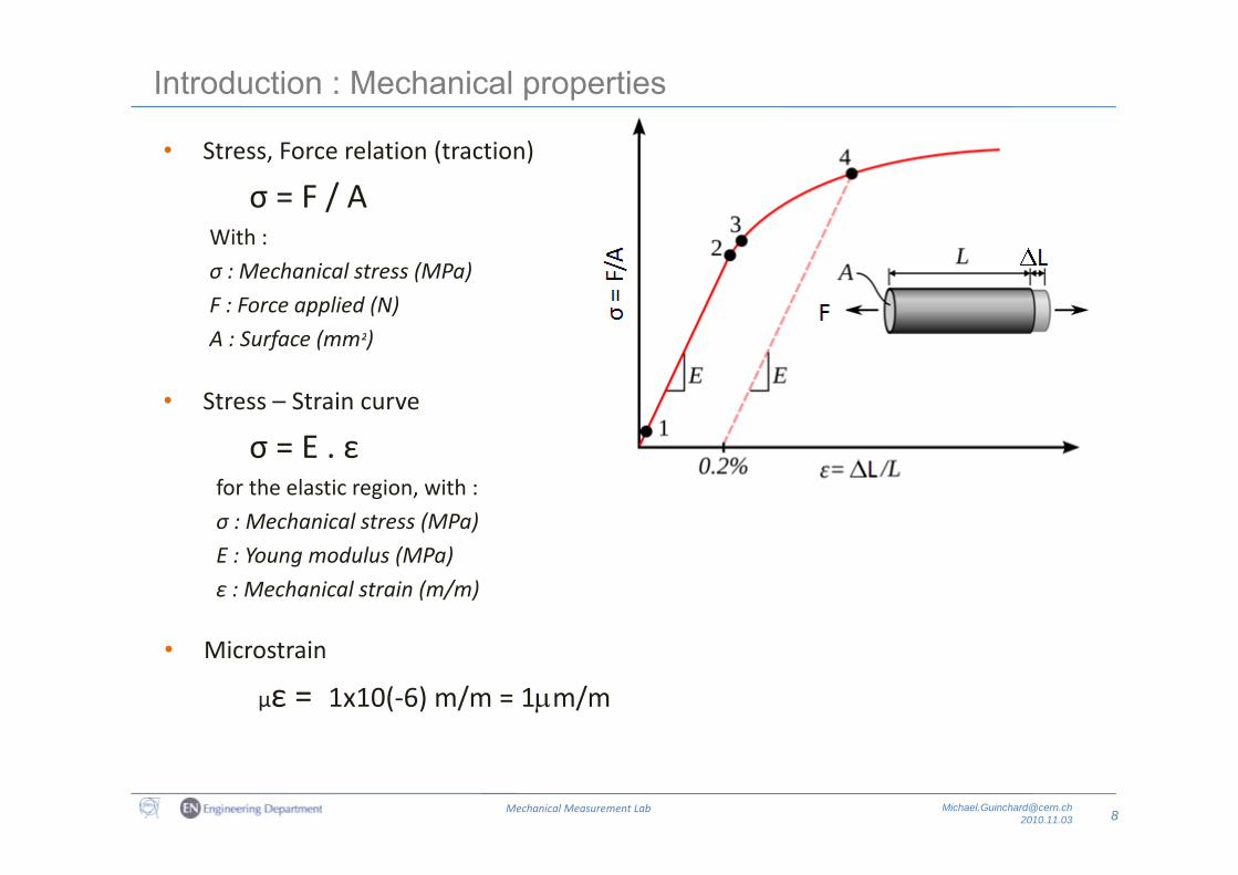
• Stress, Force relation (traction)
σ = F / AWith :With :
σ : Mechanical stress (MPa)
F : Force applied (N)
A : Surface (mm²)A : Surface (mm²)
• Stress – Strain curve
Eσ = E . εfor the elastic region, with :
σ : Mechanical stress (MPa)
E : Young modulus (MPa)
ε : Mechanical strain (m/m)
• Microstrain
με = 1x10(‐6) m/m = 1m/m
8Mechanical Measurement Lab [email protected]
Measurements with Strain gauges
Strain gauges : Introduction
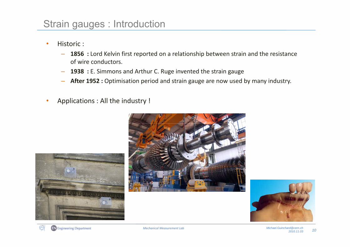
• Historic :– 1856 : Lord Kelvin first reported on a relationship between strain and the resistance
of wire conductors.
– 1938 : E. Simmons and Arthur C. Ruge invented the strain gauge
– After 1952 : Optimisation period and strain gauge are now used by many industry.
• Applications : All the industry !
10Mechanical Measurement Lab [email protected]
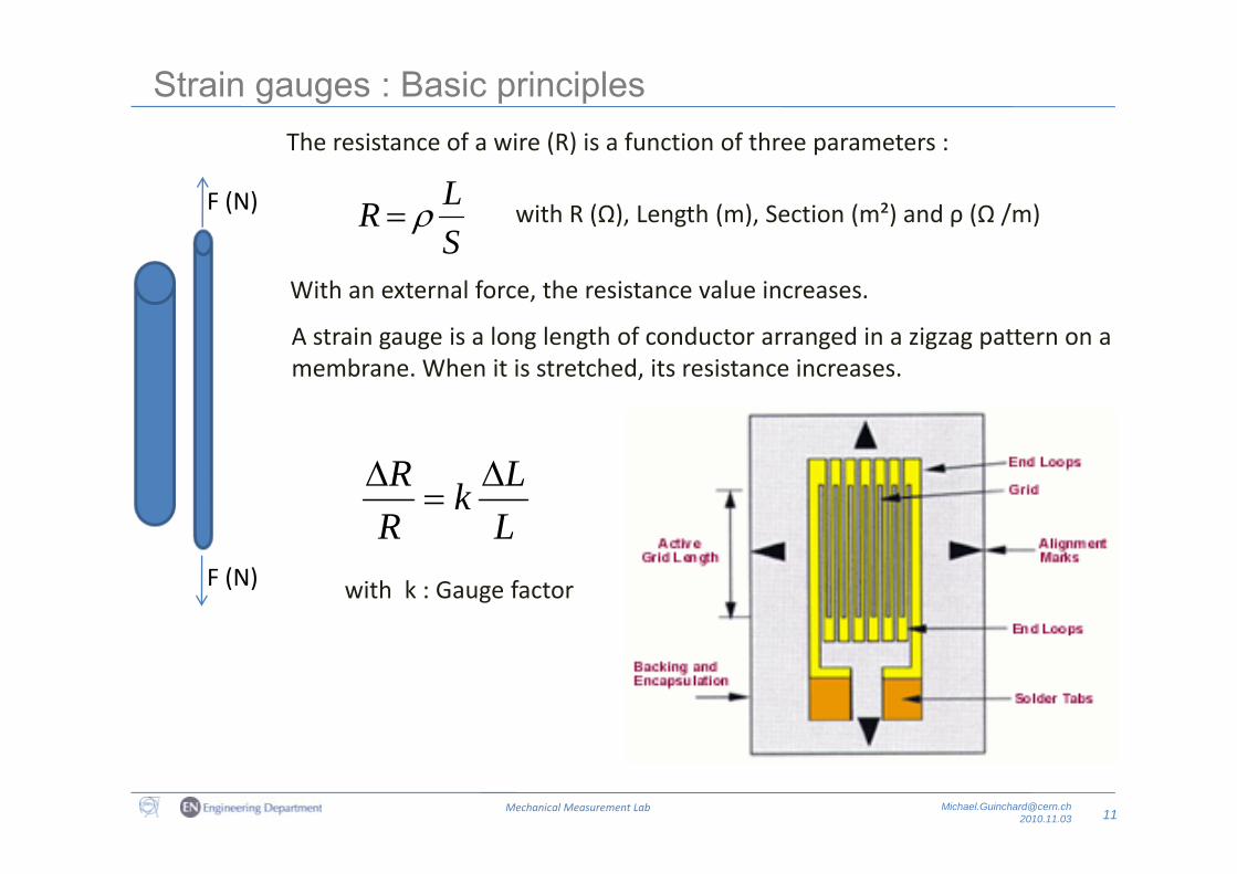
Strain gauges : Basic principles The resistance of a wire (R) is a function of three parameters :The resistance of a wire (R) is a function of three parameters :
SLR F (N) with R (Ω), Length (m), Section (m²) and ρ (Ω /m)S
With an external force, the resistance value increases.
A strain gauge is a long length of conductor arranged in a zigzag pattern on aA strain gauge is a long length of conductor arranged in a zigzag pattern on a membrane. When it is stretched, its resistance increases.
LLk
RR
with k : Gauge factor
LRF (N)
11Mechanical Measurement Lab [email protected]
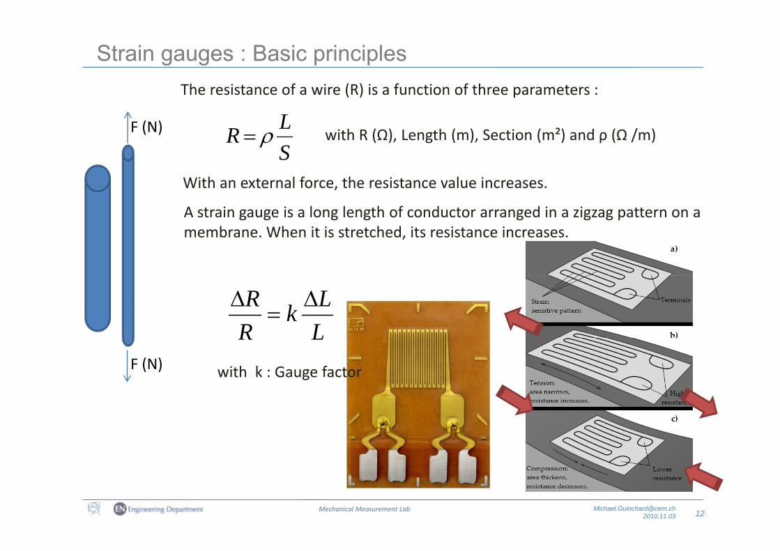
Strain gauges : Basic principles The resistance of a wire (R) is a function of three parameters :The resistance of a wire (R) is a function of three parameters :
SLR F (N) with R (Ω), Length (m), Section (m²) and ρ (Ω /m)S
With an external force, the resistance value increases.
A strain gauge is a long length of conductor arranged in a zigzag pattern on aA strain gauge is a long length of conductor arranged in a zigzag pattern on a membrane. When it is stretched, its resistance increases.
LLk
RR
with k : Gauge factor
LRF (N)
12Mechanical Measurement Lab [email protected]
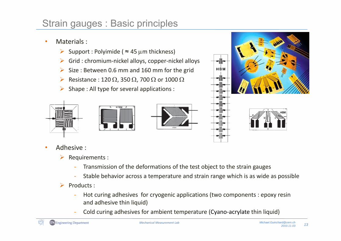
Strain gauges : Basic principles
Support : Polyimide ( ≈ 45 m thickness) Grid : chromium‐nickel alloys, copper‐nickel alloys
• Materials :
Size : Between 0.6 mm and 160 mm for the grid
Resistance : 120 , 350 , 700 or 1000 Shape : All type for several applications :
• Adhesive :• Adhesive : Requirements :
‐ Transmission of the deformations of the test object to the strain gauges
Stable behavior across a temperature and strain range which is as wide as possible‐ Stable behavior across a temperature and strain range which is as wide as possible
Products :
‐ Hot curing adhesives for cryogenic applications (two components : epoxy resin and adhesive thin liquid)
13Mechanical Measurement Lab [email protected]
and adhesive thin liquid)
‐ Cold curing adhesives for ambient temperature (Cyano‐acrylate thin liquid)
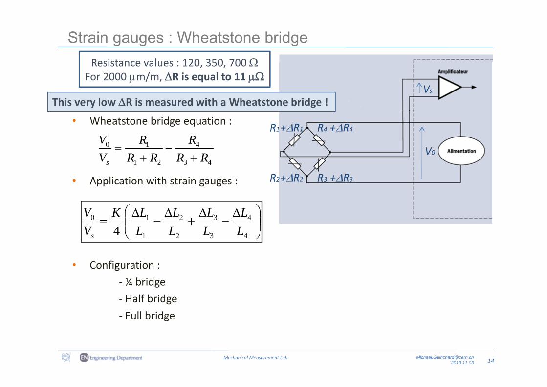
Strain gauges : Wheatstone bridgeResistance values : 120 350 700Resistance values : 120, 350, 700
For 2000 m/m, R is equal to 11
This very low R is measured with a Wheatstone bridge !Vs
This very low R is measured with a Wheatstone bridge !
• Wheatstone bridge equation :
410 RRV
+R1 +R4
V
R1 R4
4321 RRRRVs
• Application with strain gauges : +R2 +R3
V0
R2 R3
4
4
3
3
2
2
1
10
4 LL
LL
LL
LLK
VV
s 4321s
• Configuration :
¼ bridge‐ ¼ bridge
‐ Half bridge
‐ Full bridge
14Mechanical Measurement Lab [email protected]
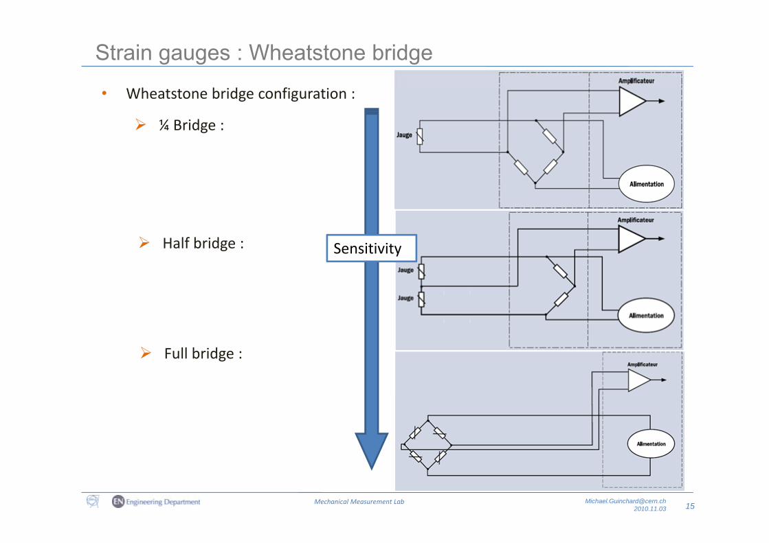
Strain gauges : Wheatstone bridge
• Wheatstone bridge configuration :
¼ Bridge :
Half bridge : Sensitivity
Full bridge :
15Mechanical Measurement Lab [email protected]
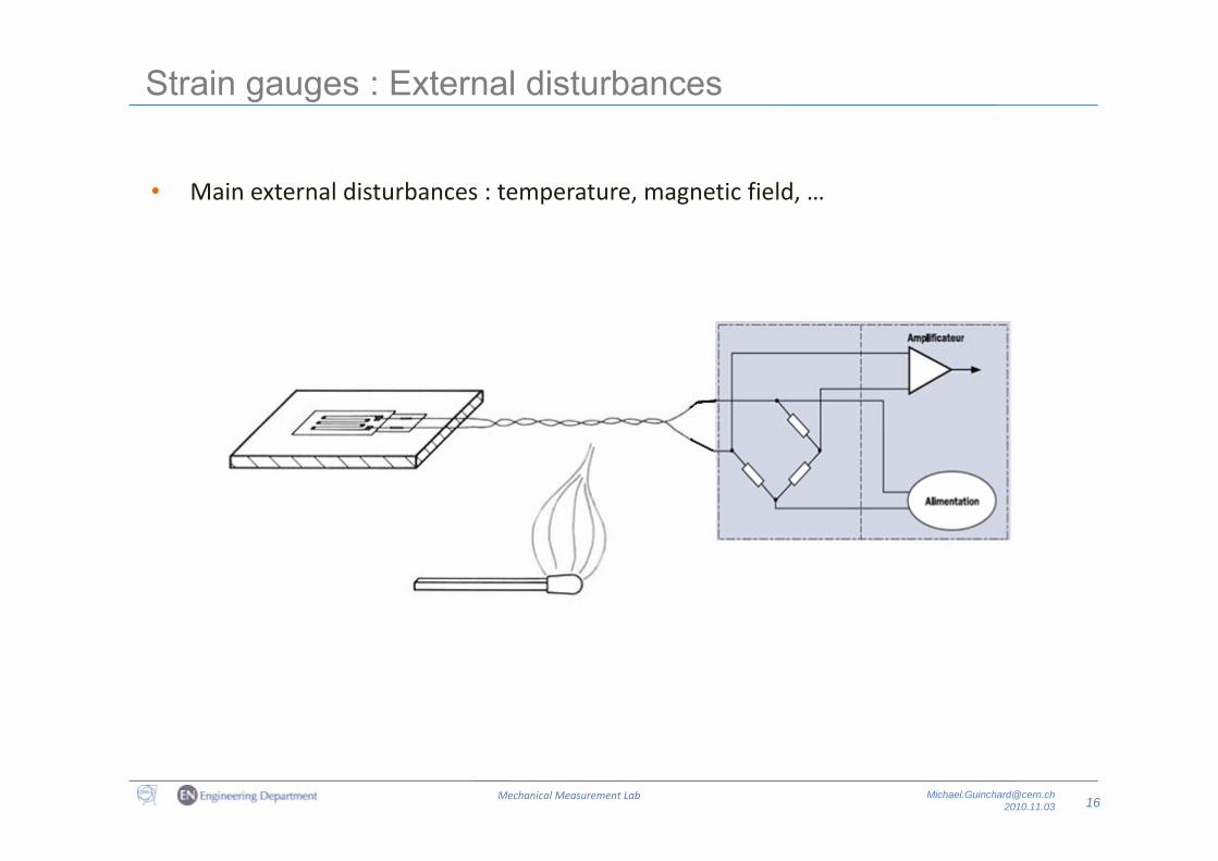
Strain gauges : External disturbances
• Main external disturbances : temperature, magnetic field, …
16Mechanical Measurement Lab [email protected]
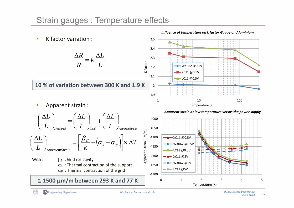
Strain gauges : Temperature effectsInfluence of temperature on k factor Gauge on Aluminium
• K factor variation :
LR 2 3
2.4
2.5
Influence of temperature on k factor Gauge on Aluminium
LLk
RR
2.1
2.2
2.3
K Factor
WK062 @0.5V
XC11 @0.5V
LC11 @0.5V
A t t i
10 % of variation between 300 K and 1.9 K1.9
2
1 10 100(K)• Apparent strain :
ld LL
LL
LL
Temperature (K)
4050
‐4000
Apparent strain at low temperature versus the power supply
rainApparentStalMeasured LLL Re
TkL
Lgs
G
rainApparentSt
‐4150
‐4100
‐4050
t Strain (um/m
)
XC11 @0.5V
WK062 @0.5V
LC11 @0.5Vpp
With : g : Grid resistivity s : Thermal contraction of the supportg : Thermal contraction of the grid
‐4300
‐4250
‐4200
App
aren
t LC11 @0.5V
XC11 @5V
WK062 @5V
LC11 @5V
17Mechanical Measurement Lab [email protected]
1500 m/m between 293 K and 77 K4300
0 1 2 3 4 5Temperature (K)
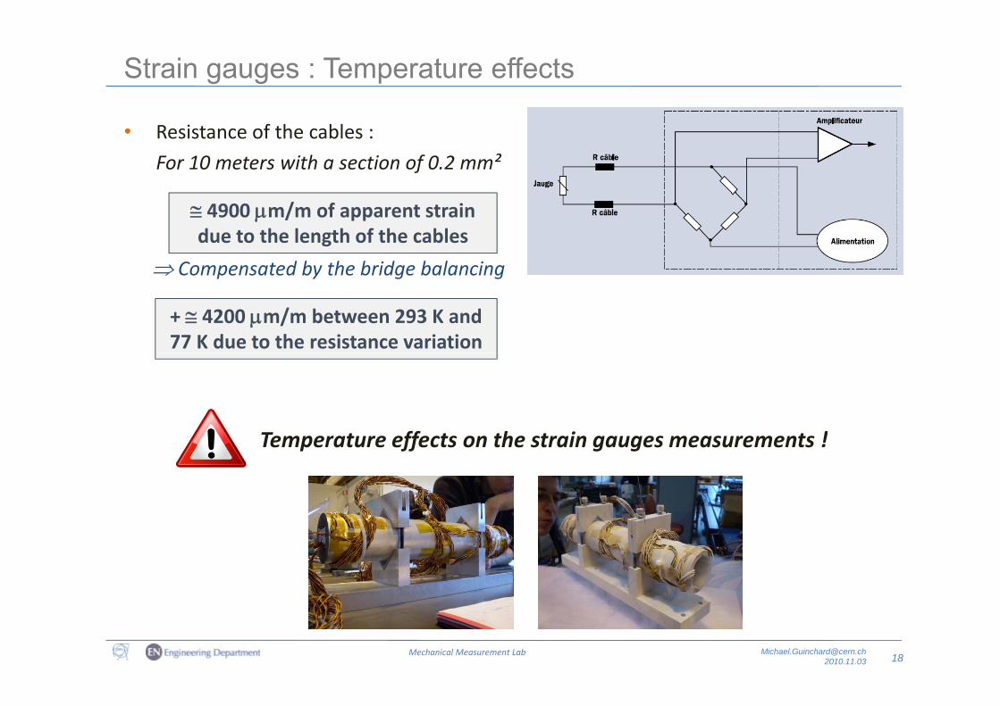
Strain gauges : Temperature effects
• Resistance of the cables :
For 10 meters with a section of 0.2 mm²
Compensated by the bridge balancing
4900 m/m of apparent strain due to the length of the cables
Compensated by the bridge balancing
+ 4200 m/m between 293 K and 77 K due to the resistance variation
T t ff t th t i t !Temperature effects on the strain gauges measurements !
18Mechanical Measurement Lab [email protected]
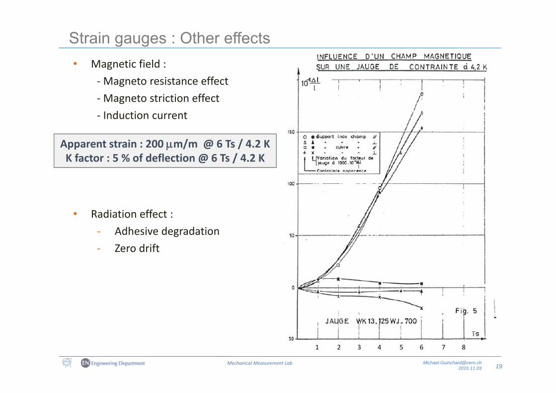
Strain gauges : Other effects• Magnetic field :• Magnetic field :
‐Magneto resistance effect
‐Magneto striction effect
‐ Induction current
Apparent strain : 200 m/m @ 6 Ts / 4.2 KK factor : 5 % of deflection @ 6 Ts / 4.2 K
• Radiation effect :
‐ Adhesive degradation
‐ Zero drift
19Mechanical Measurement Lab [email protected]
1 2 3 4 5 6 7 8
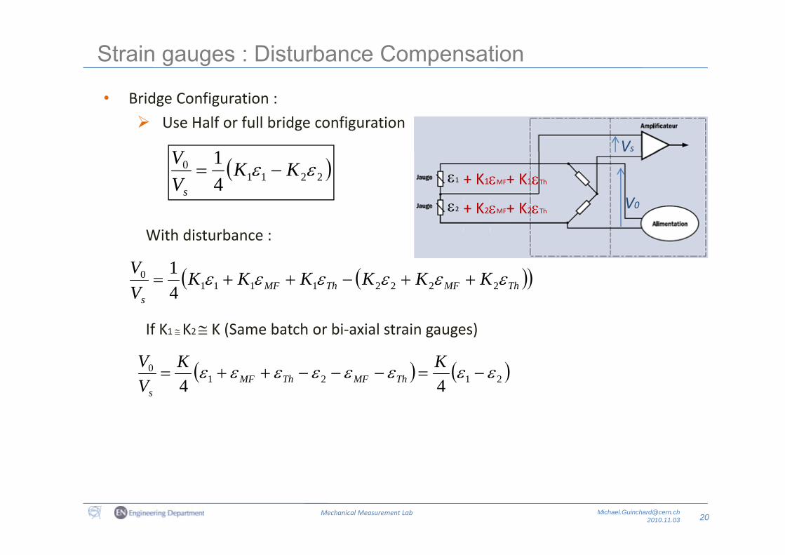
Strain gauges : Disturbance Compensation
Vs
• Bridge Configuration :
Use Half or full bridge configuration
1V
V0
22110
41 KK
VV
s
1
2
+ K1MF+ K1Th
+ K2MF+ K2Th
With disturbance :
KKKKKKV 0 1 ThMFThMF
s
KKKKKKV
222211110
4
If K1 K2 K (Same batch or bi‐axial strain gauges)
21210
4
4
KKVV
ThMFThMFs
20Mechanical Measurement Lab [email protected]
Strain gauges : Disturbance Compensation
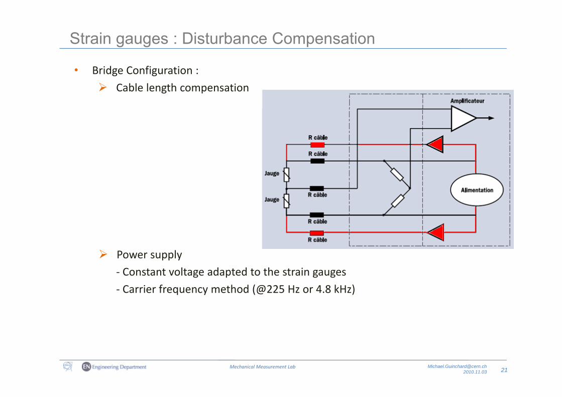
• Bridge Configuration :
Cable length compensation
Power supply
‐ Constant voltage adapted to the strain gauges
Carrier frequency method (@225 Hz or 4 8 kHz)‐ Carrier frequency method (@225 Hz or 4.8 kHz)
21Mechanical Measurement Lab [email protected]
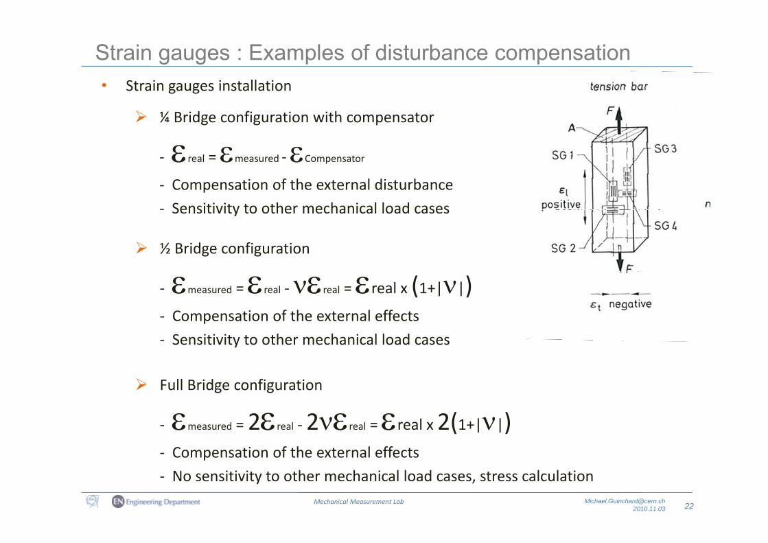
Strain gauges : Examples of disturbance compensation• Strain gauges installation• Strain gauges installation
¼ Bridge configuration with compensator
‐ real = measured ‐Compensator
‐ Compensation of the external disturbance
‐ Sensitivity to other mechanical load cases
Thermal compensator
Sensitivity to other mechanical load cases
½ Bridge configuration
‐ measured = real ‐real = real x (1+||)‐ Compensation of the external effects
Full Bridge configuration
‐ Sensitivity to other mechanical load cases
‐ measured = 2real ‐2real = real x 2(1+||)‐ Compensation of the external effects
22Mechanical Measurement Lab [email protected]
Compensation of the external effects
‐ No sensitivity to other mechanical load cases, stress calculation
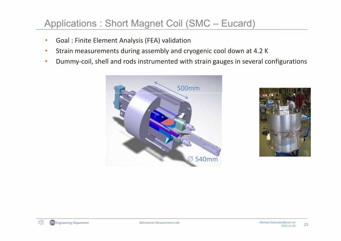
Applications : Short Magnet Coil (SMC – Eucard)G l Fi it El t A l i (FEA) lid ti• Goal : Finite Element Analysis (FEA) validation
• Strain measurements during assembly and cryogenic cool down at 4.2 K
• Dummy‐coil, shell and rods instrumented with strain gauges in several configurations
500mm
540mm
23Mechanical Measurement Lab [email protected]
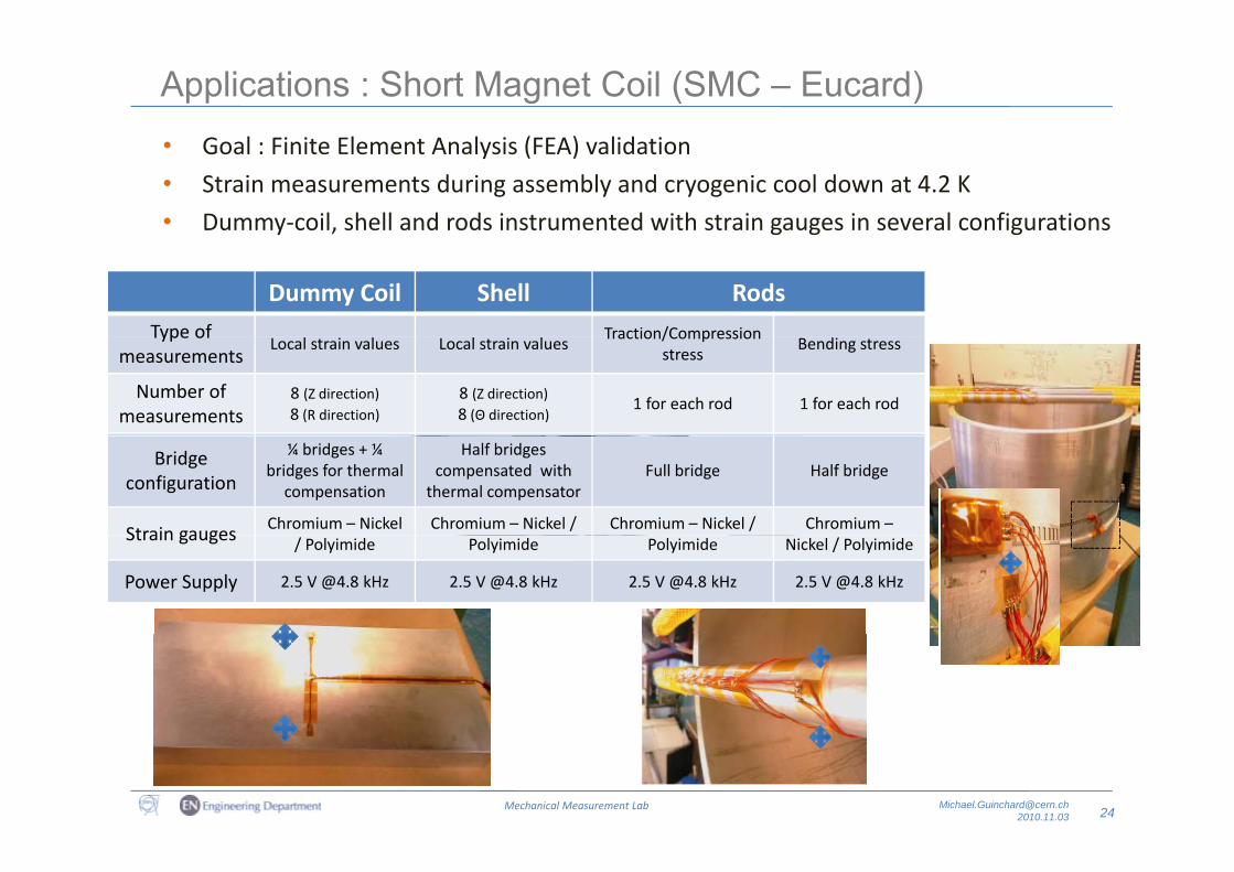
Applications : Short Magnet Coil (SMC – Eucard)G l Fi it El t A l i (FEA) lid ti• Goal : Finite Element Analysis (FEA) validation
• Strain measurements during assembly and cryogenic cool down at 4.2 K
• Dummy‐coil, shell and rods instrumented with strain gauges in several configurations
500mmDummy Coil Shell Rods
Type of Traction/CompressionType of measurements
Local strain values Local strain valuesTraction/Compression
stressBending stress
Number of measurements
8 (Z direction)8 (R direction)
8 (Z direction)8 (Θ direction)
1 for each rod 1 for each rod
Bridge configuration
¼ bridges + ¼ bridges for thermal
compensation
Half bridgescompensated with
thermal compensatorFull bridge Half bridge
Strain gauges Chromium – Nickel Chromium – Nickel / Chromium – Nickel / Chromium –
540mm
Strain gauges / Polyimide Polyimide Polyimide Nickel / Polyimide
Power Supply 2.5 V @4.8 kHz 2.5 V @4.8 kHz 2.5 V @4.8 kHz 2.5 V @4.8 kHz
24Mechanical Measurement Lab [email protected]
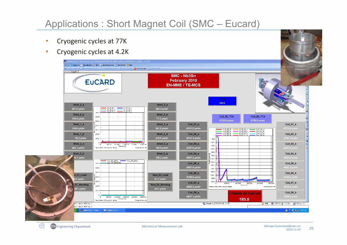
Applications : Short Magnet Coil (SMC – Eucard)C i l t 77K• Cryogenic cycles at 77K
• Cryogenic cycles at 4.2K
25Mechanical Measurement Lab [email protected]
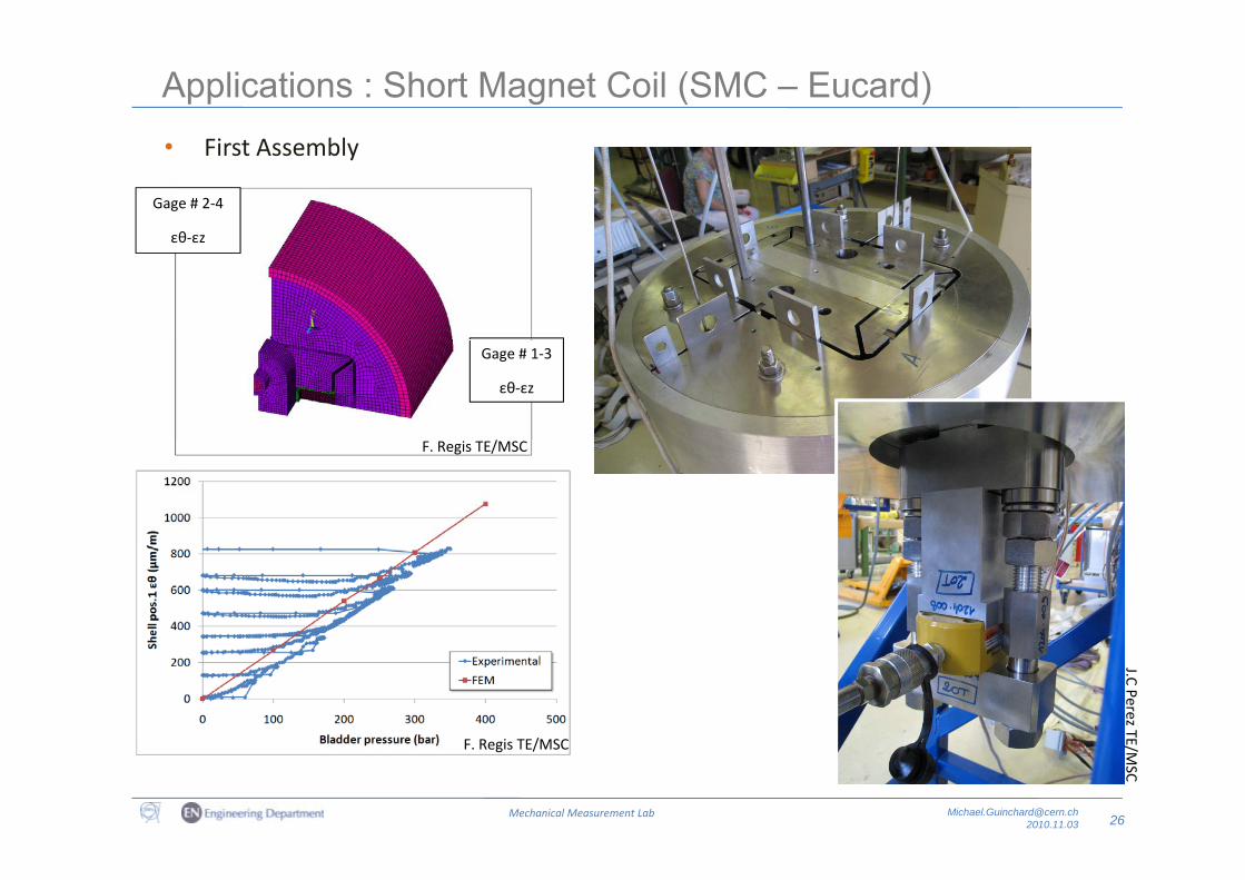
Applications : Short Magnet Coil (SMC – Eucard)Fi t A bl• First Assembly
Gage # 2‐4
εθ‐εzεθ εz
/
Gage # 1‐3
εθ‐εz
F. Regis TE/MSC
F R i TE/MSC
J.C Perez TE
26Mechanical Measurement Lab [email protected]
F. Regis TE/MSC
E/MSC
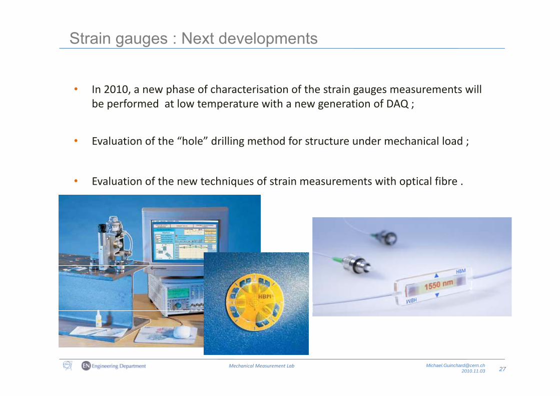
Strain gauges : Next developments
• In 2010, a new phase of characterisation of the strain gauges measurements will be performed at low temperature with a new generation of DAQ ;p p g Q ;
• Evaluation of the “hole” drilling method for structure under mechanical load ;
• Evaluation of the new techniques of strain measurements with optical fibre .
27Mechanical Measurement Lab [email protected]
Measurements with Capacitive gauges
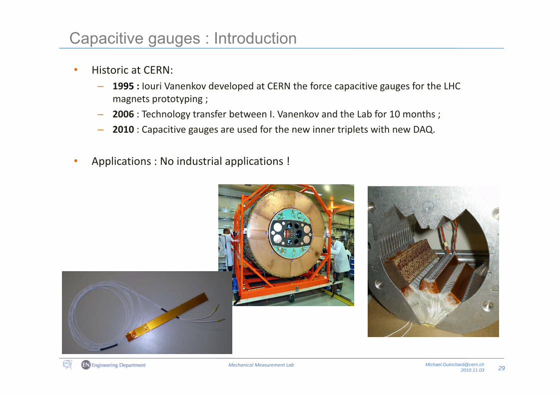
Capacitive gauges : Introduction
• Historic at CERN:– 1995 : Iouri Vanenkov developed at CERN the force capacitive gauges for the LHC
magnets prototyping ;
– 2006 : Technology transfer between I. Vanenkov and the Lab for 10 months ;
– 2010 : Capacitive gauges are used for the new inner triplets with new DAQ.
• Applications : No industrial applications !
29Mechanical Measurement Lab [email protected]
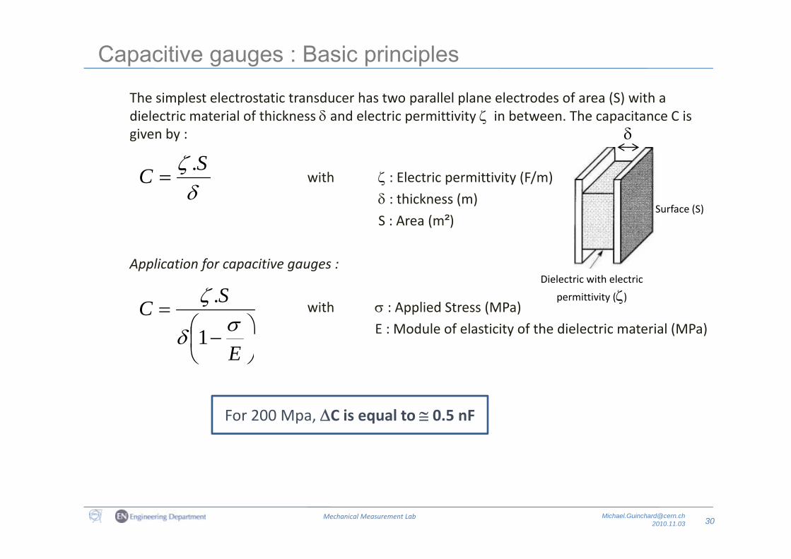
Capacitive gauges : Basic principles
The simplest electrostatic transducer has two parallel plane electrodes of area (S) with a dielectric material of thickness and electric permittivity in between. The capacitance C is given by :
with : Electric permittivity (F/m)
: thickness (m)
S A ( ²)
SC .
Surface (S)
S : Area (m²)
Application for capacitive gauges :Dielectric with electric
with : Applied Stress (MPa)E : Module of elasticity of the dielectric material (MPa)
SC
1
.Dielectric with electric
permittivity ()
E
1
For 200 Mpa, C is equal to 0.5 nF
30Mechanical Measurement Lab [email protected]
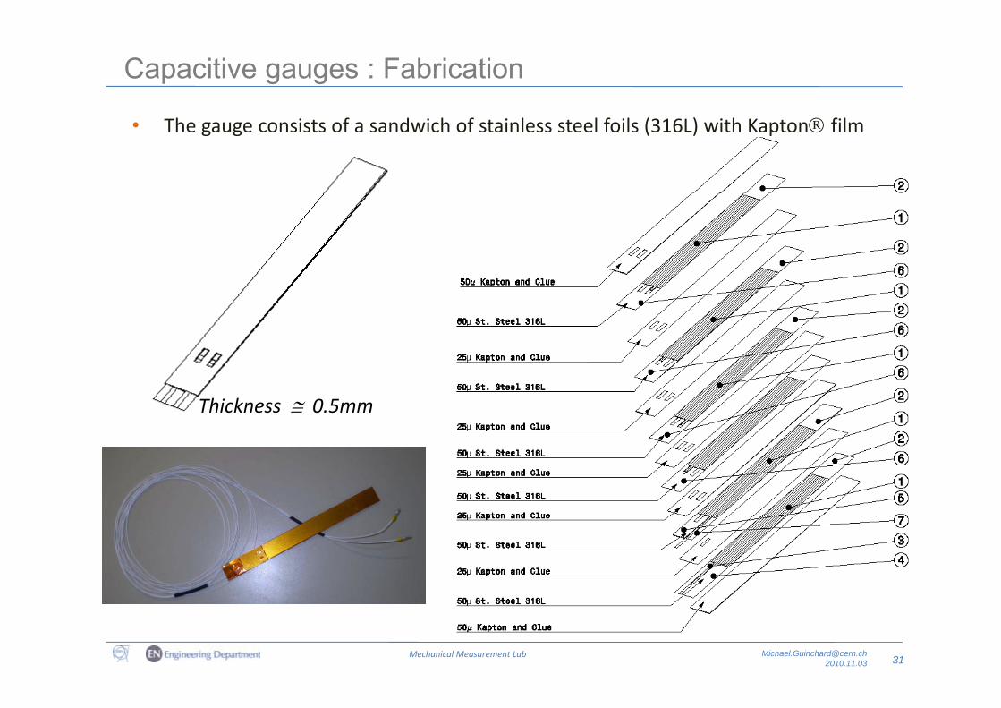
Capacitive gauges : Fabrication
• The gauge consists of a sandwich of stainless steel foils (316L) with Kapton film glued.
Thickness 0.5mm
31Mechanical Measurement Lab [email protected]
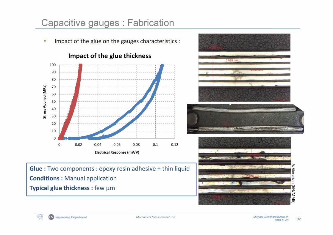
Capacitive gauges : Fabrication
• Impact of the glue on the gauges characteristics :
100
Impact of the glue thickness
70
80
90
100
MPa
)
30
40
50
60
Stress App
lied (M
0
10
20
0 0 02 0 04 0 06 0 08 0 1 0 12
SA. G
0 0.02 0.04 0.06 0.08 0.1 0.12
Electrical Response (mV/V)
Glue : Two components : epoxy resin adhesive + thin liquid erardin (EN/M
M
p p y q
Conditions : Manual application
Typical glue thickness : few μm
32Mechanical Measurement Lab [email protected]
ME)
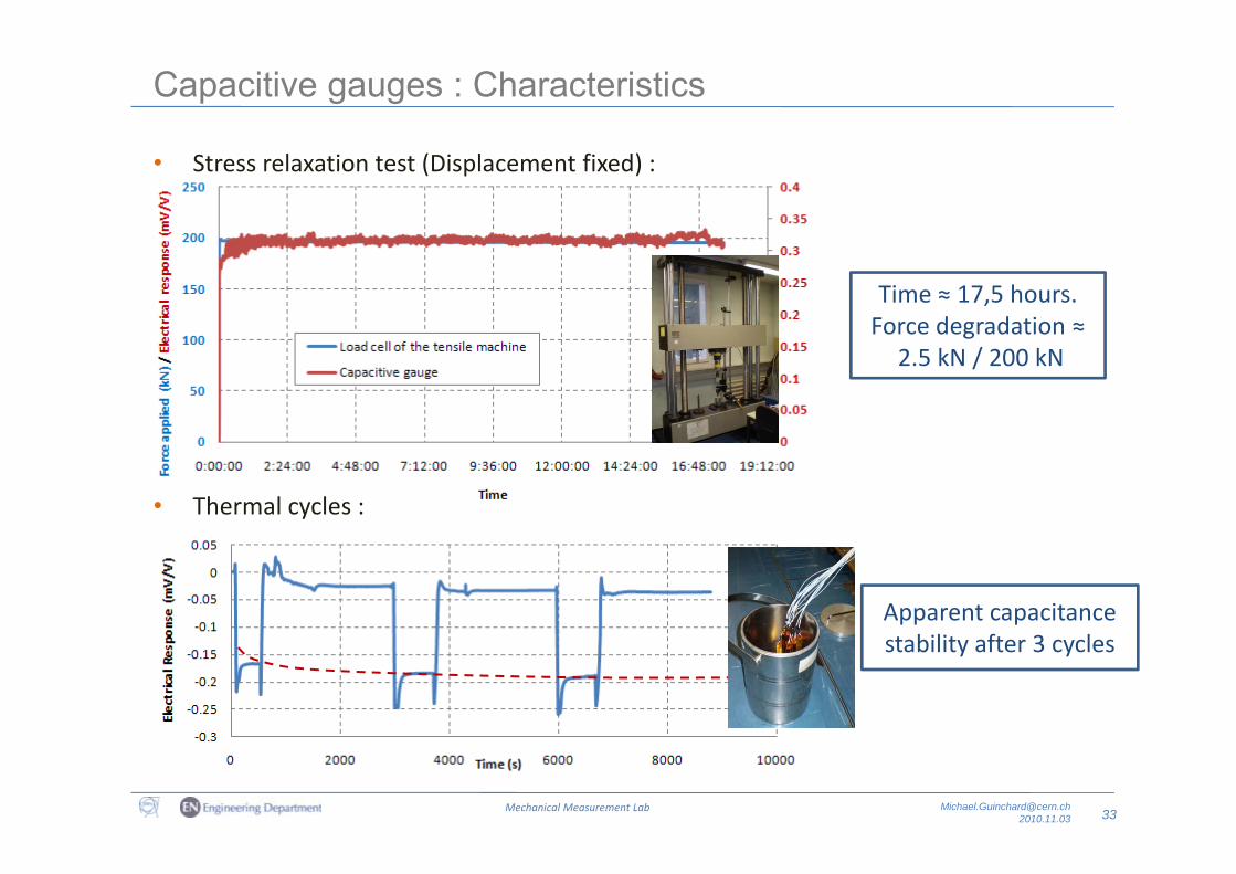
Capacitive gauges : Characteristics
• Stress relaxation test (Displacement fixed) :
Time ≈ 17,5 hours.Force degradation ≈g
2.5 kN / 200 kN
• Thermal cycles :
Apparent capacitance bili f 3 lstability after 3 cycles
33Mechanical Measurement Lab [email protected]
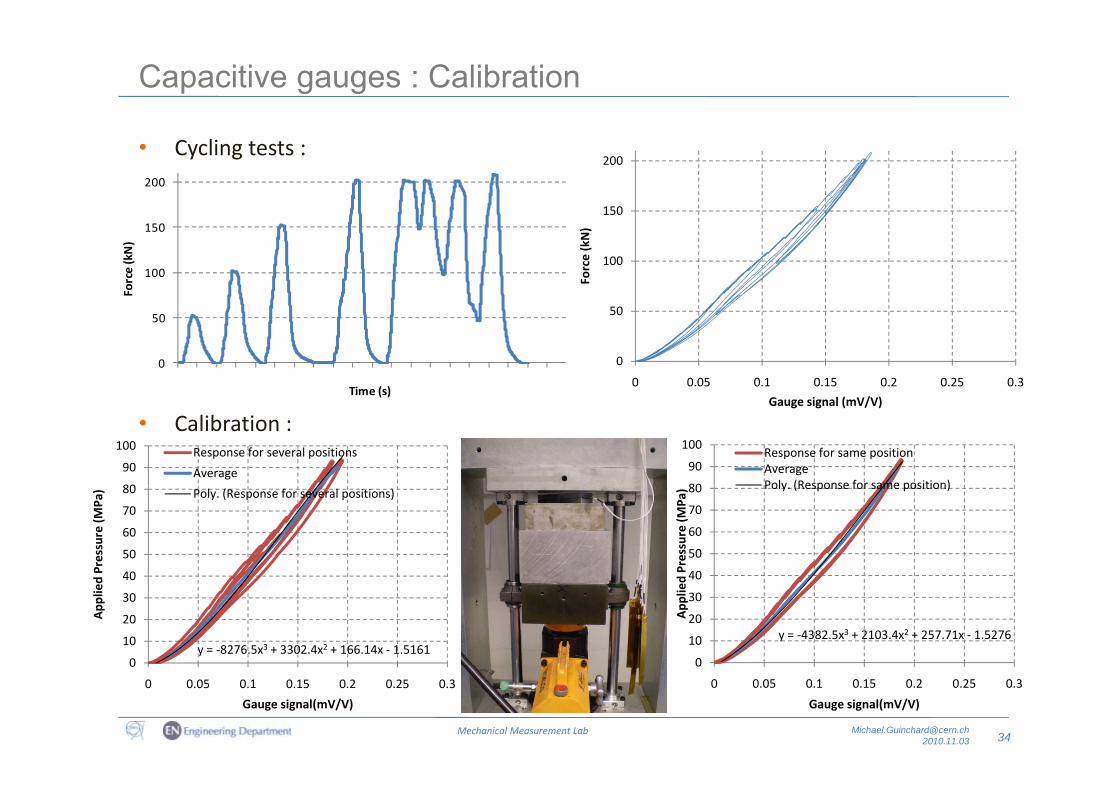
Capacitive gauges : Calibration
• Cycling tests :
150
200
200
100
Force (kN)
100
150
Force (kN)
0
50
0 0.05 0.1 0.15 0.2 0.25 0.30
50
117
534
952
369
787
104
521
939
356
774
191
508
926
343
761
178
595
913
330
748
165
582
9
Time (s)
• Calibration :
80
90
100 Response for several positions
Average80
90
100Response for same positionAveragePoly (Response for same position)
Gauge signal (mV/V)
3 5 6 8 10 12 13 15 17 19 20 22 24 26 27 29 31 33 34 36 38
( )
40
50
60
70
80
Pressure (M
Pa) Poly. (Response for several positions)
40
50
60
70
80
Pressure (M
Pa) Poly. (Response for same position)
y = ‐8276.5x3 + 3302.4x2 + 166.14x ‐ 1.51610
10
20
30
40
App
lied
y = ‐4382.5x3 + 2103.4x2 + 257.71x ‐ 1.5276
0
10
20
30
40
App
lied
34Mechanical Measurement Lab [email protected]
0
0 0.05 0.1 0.15 0.2 0.25 0.3
Gauge signal(mV/V)
0
0 0.05 0.1 0.15 0.2 0.25 0.3
Gauge signal(mV/V)
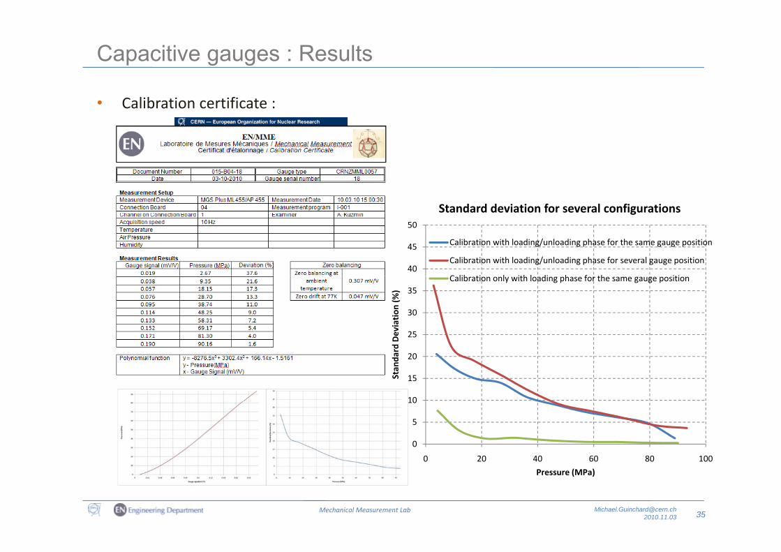
Capacitive gauges : Results
• Calibration certificate :
Standard deviation for several configurations
40
45
50
g
Calibration with loading/unloading phase for the same gauge position
Calibration with loading/unloading phase for several gauge position
C lib ti l ith l di h f th iti
25
30
35
Deviation
(%)
Calibration only with loading phase for the same gauge position
10
15
20
Stan
dard D
0
5
10
0 20 40 60 80 100
35Mechanical Measurement Lab [email protected]
Pressure (MPa)
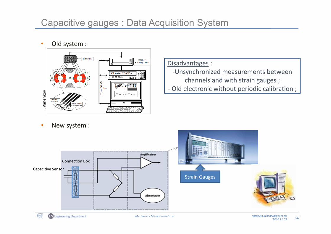
Capacitive gauges : Data Acquisition System
• Old system :
Disadvantages :Disadvantages :‐Unsynchronized measurements between
channels and with strain gauges ;‐ Old electronic without periodic calibration ;v Old electronic without periodic calibration ;
I. Va
nenkov
• New system :
Capacitive Sensor
Connection Box
Capacitive Sensor
Strain Gauges
36Mechanical Measurement Lab [email protected]
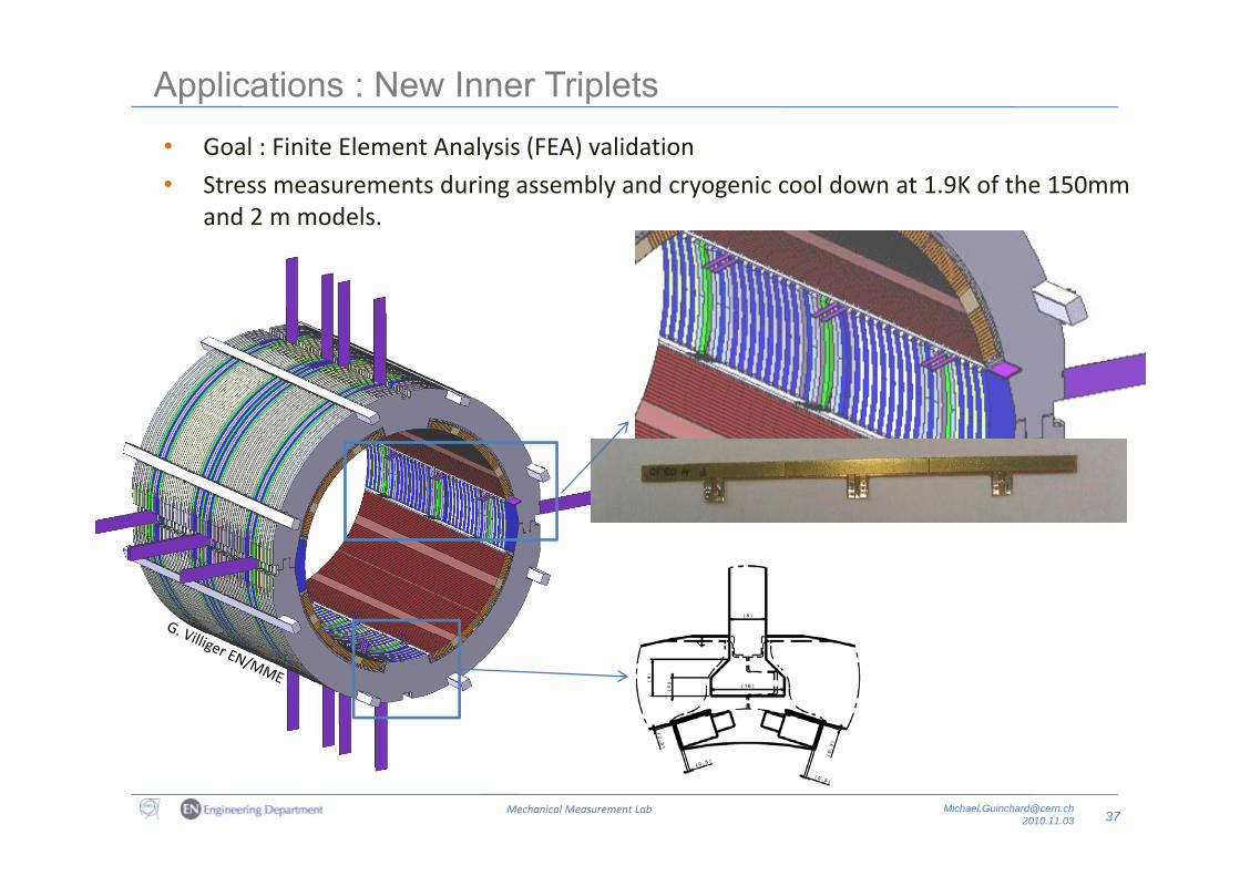
Applications : New Inner TripletsG l Fi it El t A l i (FEA) lid ti• Goal : Finite Element Analysis (FEA) validation
• Stress measurements during assembly and cryogenic cool down at 1.9K of the 150mm and 2 m models.
37Mechanical Measurement Lab [email protected]
Capacitive gauges : Next steps
• Evaluation of new adhesive ;
• New study concerning the impact of the number of stain steel layers ;• New study concerning the impact of the number of stain steel layers ;
• Collaboration with the industry to produce capacitive gauges ;
• Impact of the magnetic field ;
38Mechanical Measurement Lab [email protected]

Other Measurements
HAUG Compressors : Introduction
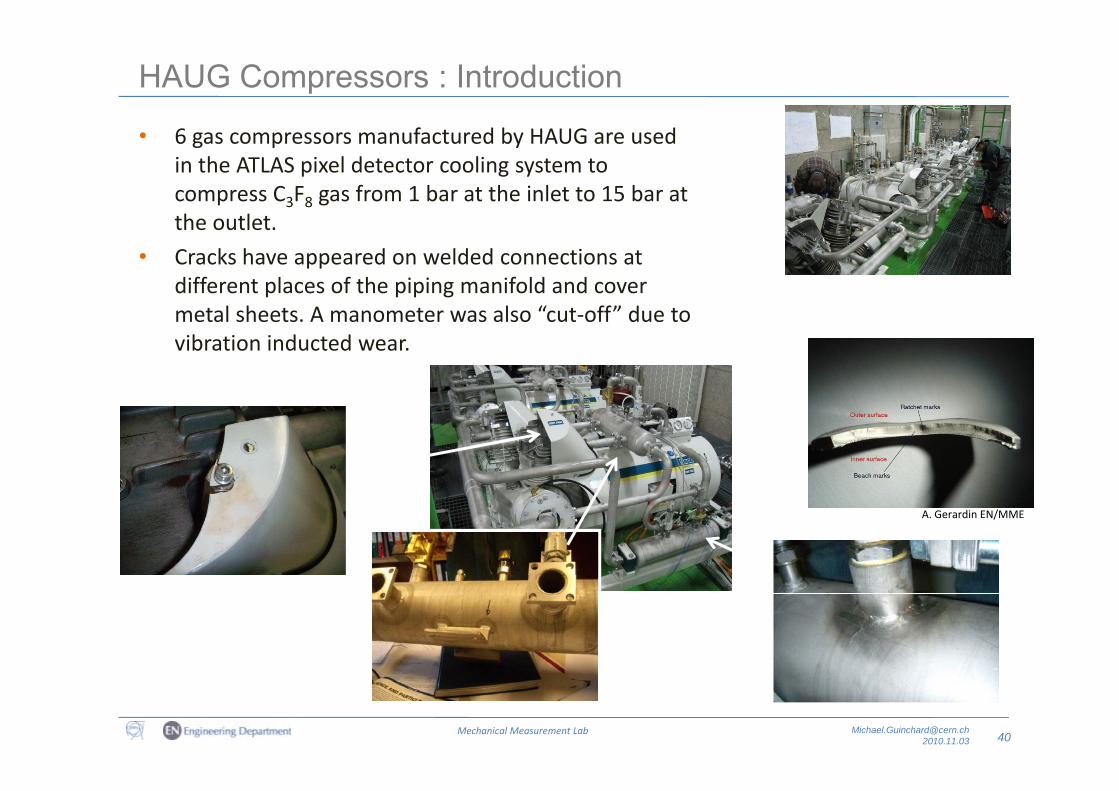
• 6 gas compressors manufactured by HAUG are used in the ATLAS pixel detector cooling system to compress C3F8 gas from 1 bar at the inlet to 15 bar at th tl tthe outlet.
• Cracks have appeared on welded connections at different places of the piping manifold and cover
l h l “ ff” dmetal sheets. A manometer was also “cut‐off” due to vibration inducted wear.
A. Gerardin EN/MME
40Mechanical Measurement Lab [email protected]
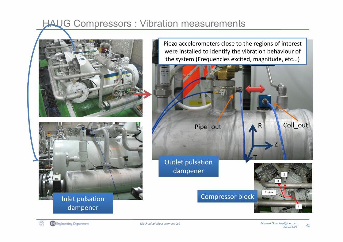
HAUG Compressors : Vibration measurements
Piezo accelerometers close to the regions of interest were installed to identify the vibration behaviour of the system (Frequencies excited, magnitude, etc...)
Pipe_out Coll_outR
Z
TOutlet pulsation
dampener
Inlet pulsation Compressor block
41Mechanical Measurement Lab [email protected]
dampener
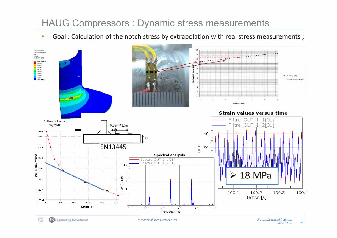
HAUG Compressors : Dynamic stress measurements• Goal : Calculation of the notch stress by extrapolation with real stress measurements ;Goal : Calculation of the notch stress by extrapolation with real stress measurements ;
D. Duarte Ramos EN/MME
EN13445
18 MP
EN13445
18 MPa
42Mechanical Measurement Lab [email protected]
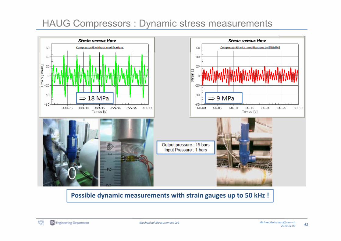
HAUG Compressors : Dynamic stress measurements
Possible dynamic measurements with strain gauges up to 50 kHz !
43Mechanical Measurement Lab [email protected]
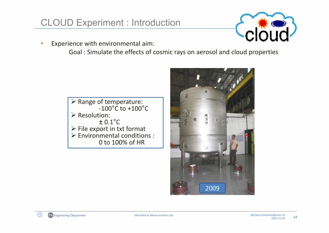
CLOUD Experiment : Introduction
• Experience with environmental aim:Goal : Simulate the effects of cosmic rays on aerosol and cloud properties
Range of temperature:‐100°C to +100°C
Resolution: Resolution:± 0.1°C
File export in txt format Environmental conditions :
0 to 100% of HR0 to 100% of HR
2009
44Mechanical Measurement Lab [email protected]
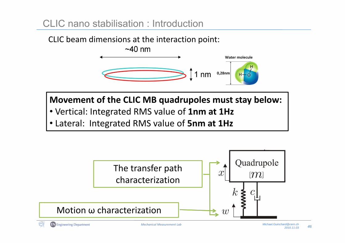
CLIC nano stabilisation : IntroductionCLIC beam dimensions at the interaction point:CLIC beam dimensions at the interaction point:
Movement of the CLIC MB quadrupoles must stay below:• Vertical: Integrated RMS value of 1nm at 1HzL t l I t t d RMS l f 5 t 1H• Lateral: Integrated RMS value of 5nm at 1Hz
The transfer path h i icharacterization
46Mechanical Measurement Lab [email protected]
Motion ω characterization
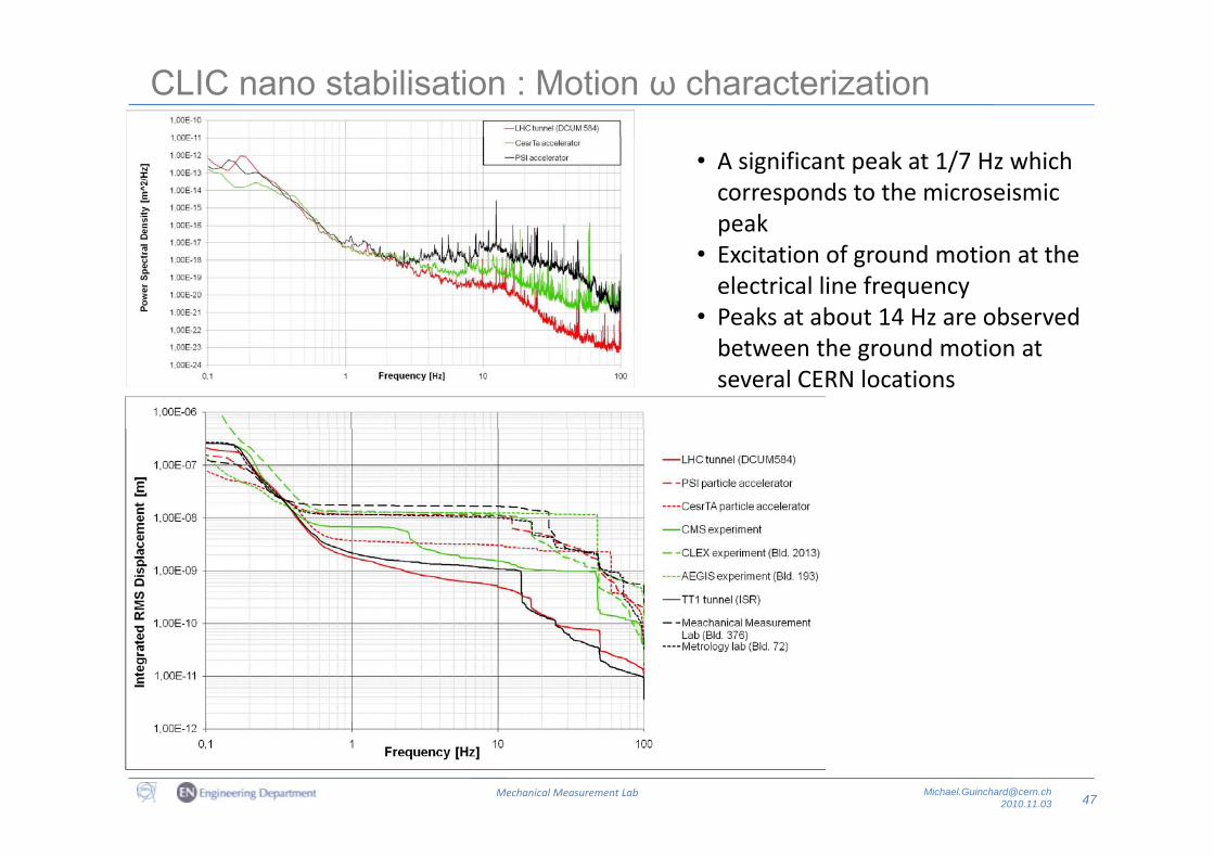
CLIC nano stabilisation : Motion ω characterization
• A significant peak at 1/7 Hz which corresponds to the microseismic peakp
• Excitation of ground motion at the electrical line frequency
• Peaks at about 14 Hz are observed between the ground motion at several CERN locations
47Mechanical Measurement Lab [email protected]
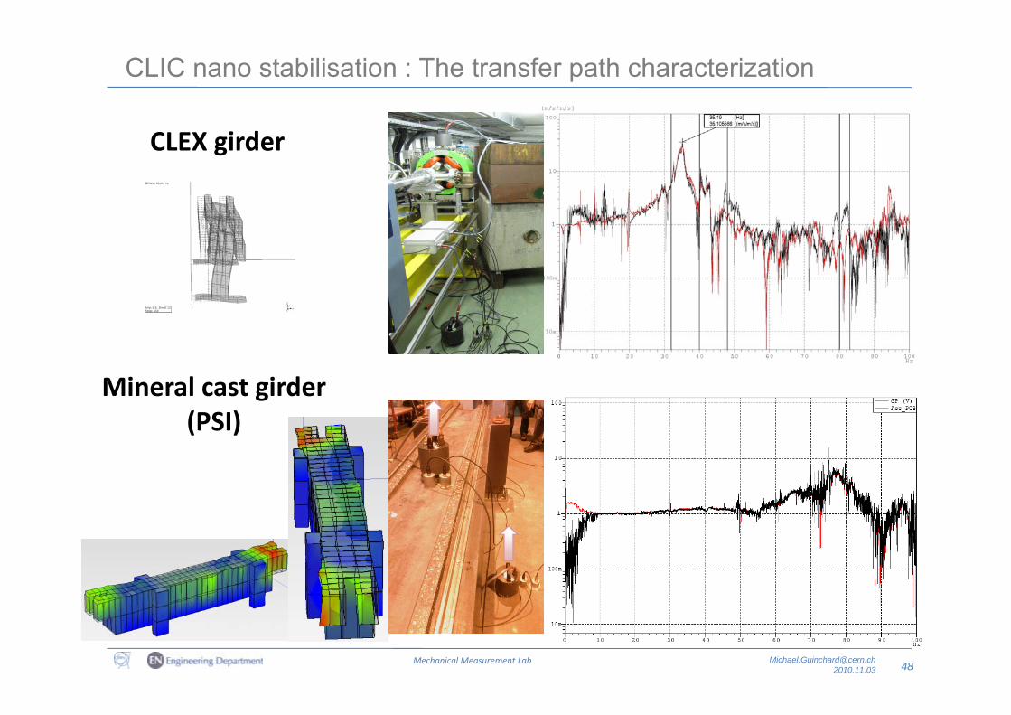
CLIC nano stabilisation : The transfer path characterization
CLEX girder
Mineral cast girder(PSI)
48Mechanical Measurement Lab [email protected]

Conclusions
Conclusion :
• The mechanical measurement lab of the EN‐MME group is able to perform mechanical measurements for CERN applications and environment.pp
• New studies are in progress to increase our knowledge concerning the behaviour of these measurement techniques in the specific CERN environment according toof these measurement techniques in the specific CERN environment according to the new industrial products (DAQ).
I th l b h t i ifi d l t ! Th h i l• In the lab, each request is a specific development ! The mechanicalmeasurements techniques, knowledge's, equipments and experience areconcentrated in the lab of the EN‐MME Group.
• For more information you can visit our Web Page at :
http://en dep web cern ch/en dep/Groups/MME/DEO/MECHANICAL LAB/default asphttp://en‐dep.web.cern.ch/en‐dep/Groups/MME/DEO/MECHANICAL‐LAB/default.asp
50Mechanical Measurement Lab [email protected]

Thanks to Alex, Andrey, Delio, Kurt, Ofelia,
Pierre, Ramon, Raphael and Stefano.
Thank you for your attention !

Q ti ?Questions ?