mechanical measurements applications.ppt
TRANSCRIPT
Mechanical Measurements Applications
ME 302
Chapters # 11,12,14,15 and 16

Chapter 11-Displacement and Dimensional Measurement
• Gauge Blocks • wringling blocks
together to make larger dimensions.
• αp = temperature coefficient of expansion of gaged part in ppm/º
• αb = temperature coefficient of expansion of gage block in ppm/º
L Lb 1 T 10 6 p b

Linear Variable Differential Transformers
LVDT For Linear
Displacement Measurements

Measuring Tools
Vernier Calipers; Resoln
0.001” & acc. ±0.001”
micrometer, Resolution
of 0.0001”

Dial Indicators
• Dials for Displacement Measurements

Chapter 12; Strain Measurements
a dL
LL2 L1
L1
LL1

Metallic Gauges
R LA
LCD2
If you have a conductor of resistivity , the resistance across that conductor is
If you strain this conductor axially, its length will increase while its cross sectional area will decrease. Taking the total differential of R,
dR R
d RL
dL R CD2
d CD2
1
CD2 Ld dL 2L dD
D
dR
RdL
L 2
dD
Dd

Metallic Gauges
dR /R
dL /L1 2
dD /D
dL /L d /dL /L
dR
RdL
L 2
dD
Dd
a dL
L
L dD
D
L
a
F dR /R
dL /LdR /R
a
1 2v d /dL /L
For most strain gauges, = 0.3. If the resistivity is not a function of strain, then F only depends on poisson’s ratio, and F ~ 1.6.
Gage factor

Strain Gauge
lateral strain
axial strain
L
a
F dR /R
dL /LdR /R
a
1 2v d /dL /L
1
F
RR
F and R are supplied by the manufacturer, and we measure ∆R.

Strain Gage Bridge Circuit
eo
ei
R1 /R
4 2 R1 /R
1
F
RR
eo eiF
4 2F
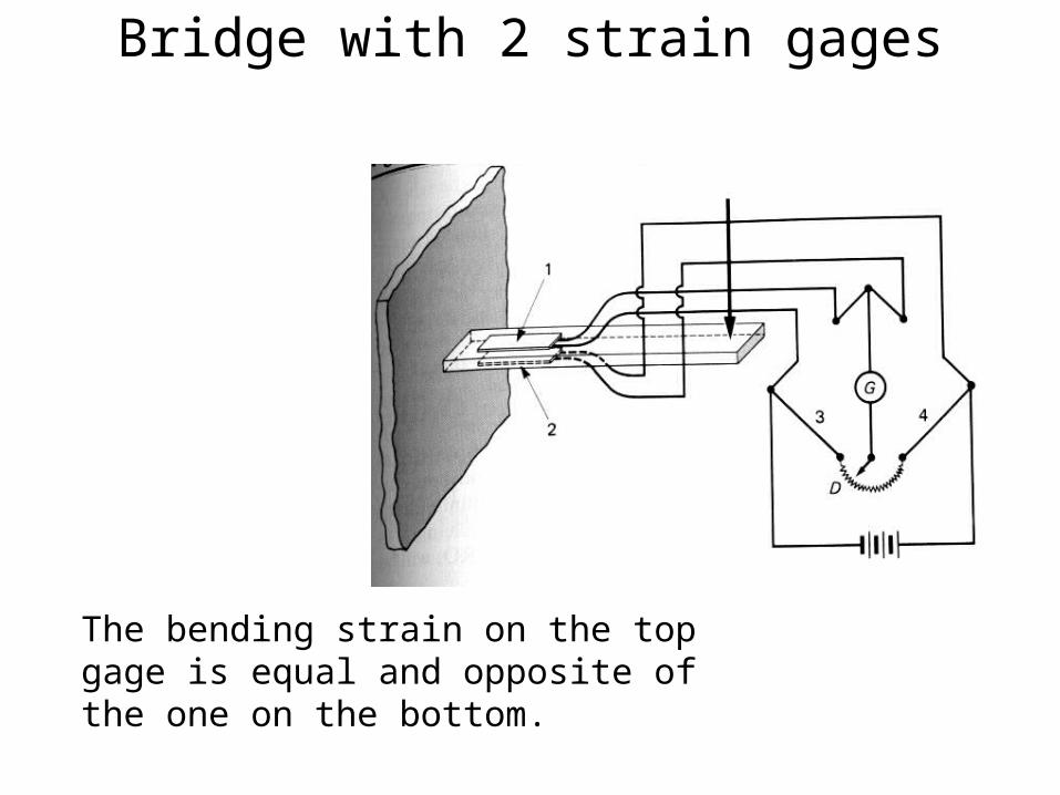
Bridge with 2 strain gages
The bending strain on the top gage is equal and opposite of the one on the bottom.
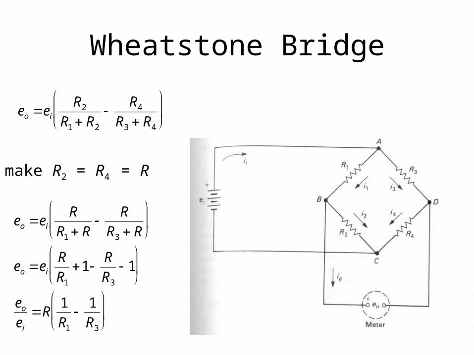
Wheatstone Bridge
eo ei
R2
R1 R2
R4
R3 R4
make R2 = R4 = R
eo ei
R
R1 R
R
R3 R
eo ei
R
R1
1R
R3
1
eo
ei
R1
R1
1
R3
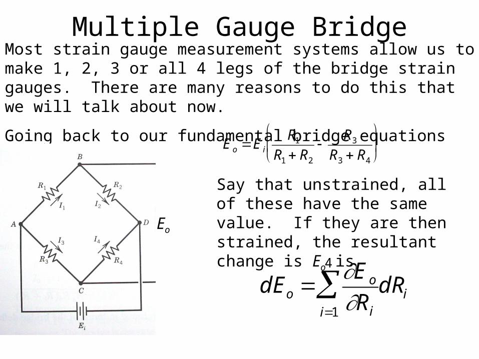
Multiple Gauge BridgeMost strain gauge measurement systems allow us to make 1, 2, 3 or all 4 legs of the bridge strain gauges. There are many reasons to do this that we will talk about now.
Going back to our fundamental bridge equations from chapter 6,
Eo E i
R1
R1 R2
R3
R3 R4
Say that unstrained, all of these have the same value. If they are then strained, the resultant change is Eo is
dEo Eo
Rii1
4
dRi
Eo
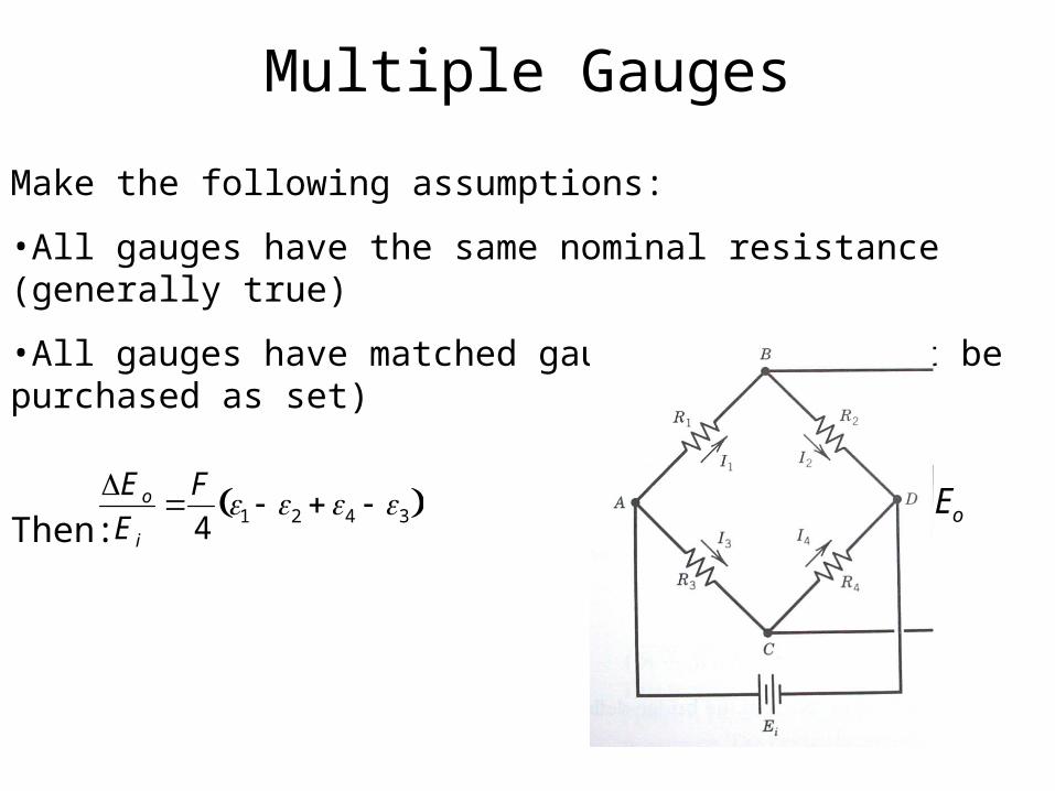
Multiple Gauges
Make the following assumptions:
•All gauges have the same nominal resistance (generally true)
•All gauges have matched gauge factors (must be purchased as set)
Then:
Eo
E i
F
41 2 4 3 Eo

Chapter 13; Force Measurements
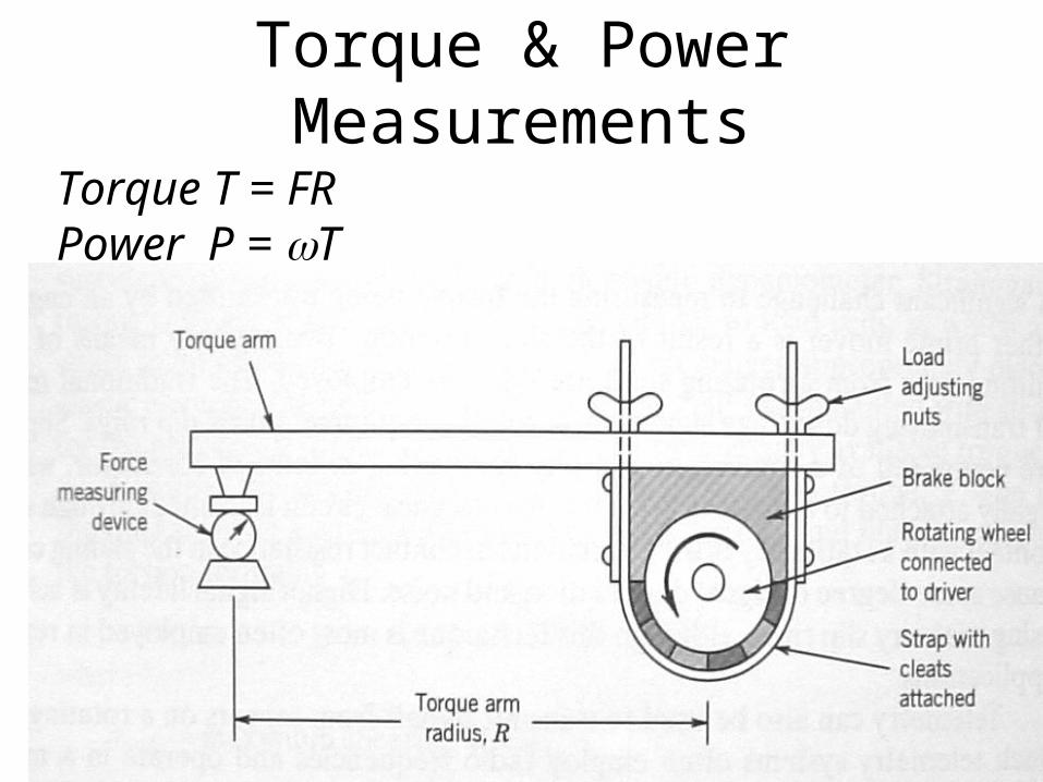
Torque & Power Measurements
Torque T = FRPower P = T

Chapter 14 Pressure
Measuring pressure is also very common and can be accomplished very cheaply or very accurately (not usually both). We are going to discuss several sensor types that are available.
Cheap Rugged, fast
Accurate

Static and Dynamic PressureDynamic Pressure = Total Pressure - Static Pressure
Use of Manometers

Deadweight Testers
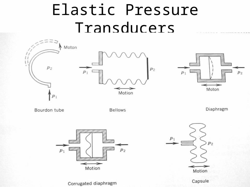
Elastic Pressure Transducers

Bourdon Tube Gauge
Pressure Measurements in a Moving Fluid
Chapter 15 Flow Measurements

Obstruction Meters
P1 P2
V2
2 V12
2gc
Qideal V2A2 A2
1 A2 /A1 2 1/ 2
2gc P1 P2

Rotameter or Area meter
Q AwC2g f f w
A f w
1/ 2
Aw 4
D by 2 d2
2% full scale

Vortex Shedding Meters
Q K1
K1 d3
4St

Pitot probe errors
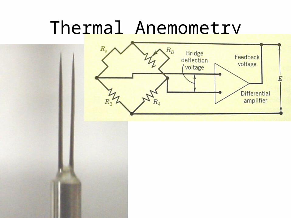
Thermal Anemometry
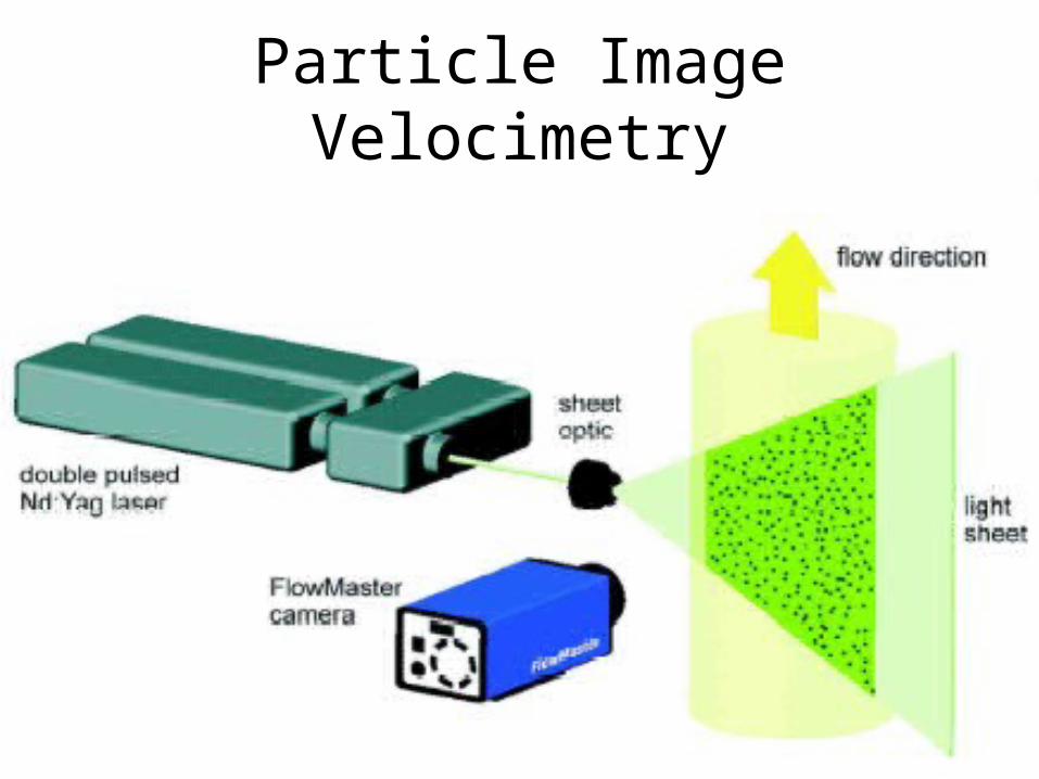
Particle Image Velocimetry

PIV
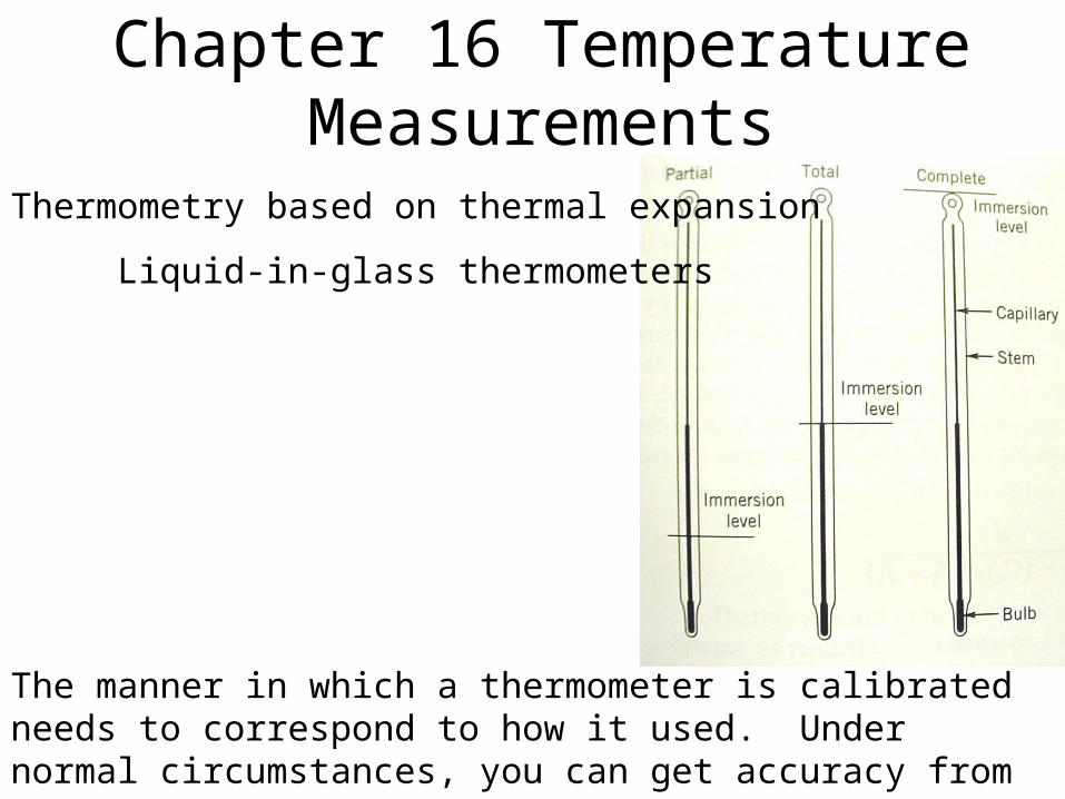
Chapter 16 Temperature Measurements
The manner in which a thermometer is calibrated needs to correspond to how it used. Under normal circumstances, you can get accuracy from ±0.2 to ±2°C.
Thermometry based on thermal expansion
Liquid-in-glass thermometers

Bimetalic ThermometersIf you take two metals with different thermal expansion coefficients and bond them together, they will bend in one direction if the temperature rises above the temperature at which the boding was done and in the other if it gets less.

Resistance Temperature Detectors RTD
R1
R2
R3 r1
RRTD r3
RRTD R3 r1 r3
R R0 1 A T T0

Thermistors
R R0e 1/T 1/T0
Usually made of a semiconductor and have the following properties:Much larger dR/dT than RTD’s, so more sensitiveRuggedFast Response

16.5 Thermoelectric Temperature Measurement
In this section, we will learn about perhaps the most important temperature measuring technique--Thermocouples.
“Electromotive Force”

Thermoelectric EffectsSeebeck Generates voltages across two dissimilar materials when a temperature difference is present.
Peltier Moves heat through dissimilar materials when current is applied.
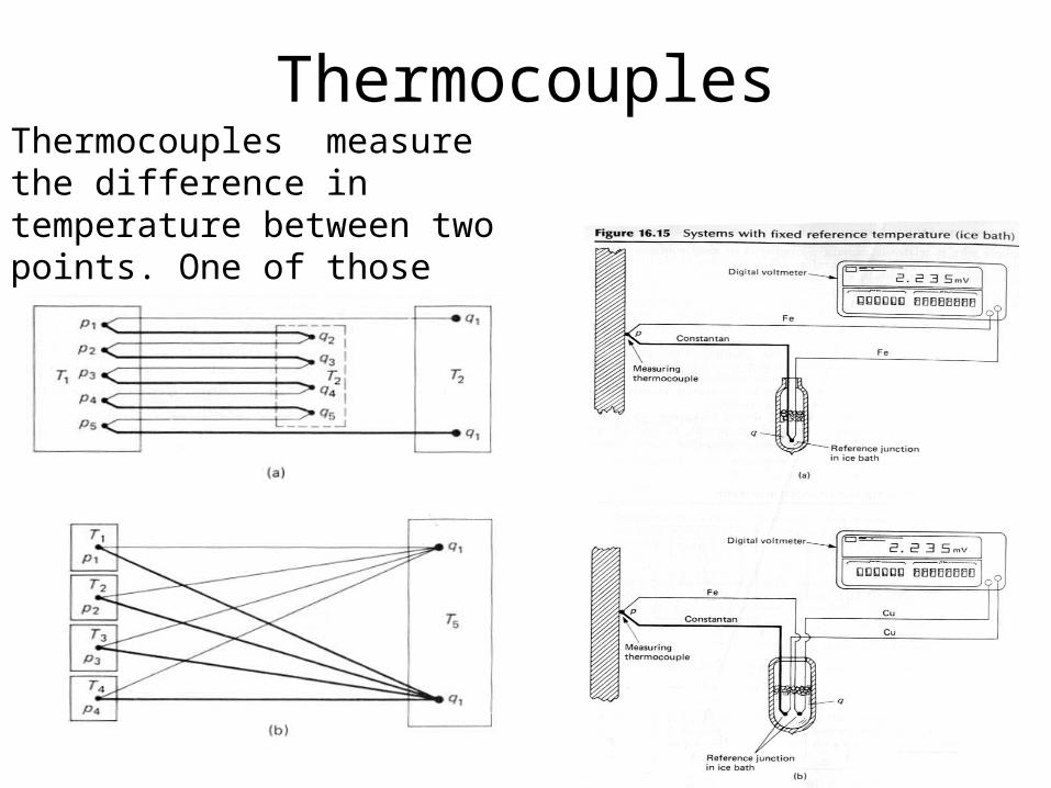
ThermocouplesThermocouples measure the difference in temperature between two points. One of those points at a known temperature.
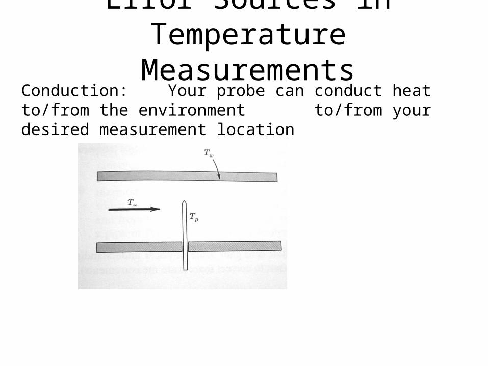
Error Sources in Temperature Measurements
Conduction: Your probe can conduct heat to/from the environment to/from your desired measurement location

Analysis of Conduction Error
qxdx qx hPdx T(x) T
T T
q kAdT
dx
m hP
kA
d2dx 2 m2 0
x w
coshmx
coshmL
0 w
T 0 T
Tw T
1
coshmL
T 0 T Tw T
coshmL
L
P/A = 4/D for round

16.8 Radiative Temperature Measurements (Pyrometry)
Eb T 4
Temperatures greater than 500ºC = 5.67•10-8 W/m2K4

Total Radiation Pyrometry
q TA4 TB
4
The radiative heat transfer between two ideal bodies A and B