technical catalogue - victor hydraulics ltd.jds-g223 quality standard, which champions customer...
TRANSCRIPT

Building on a 60-year tradition of innovation, quality and delivery
Technical Catalogue
Building on a 60-year tradition of innovation, quality and delivery
2 viCtor.Co.nZ
We believe in setting the benchmark high and then aiming even higher. it’s this belief that ensures we remain at the forefront of our industry.
Contact the victor team to discuss how we can add value to your business.
telephone +64 3 344 2700 email [email protected]
viCtor teChniCal Catalogue
t +64 3 344 2700 e [email protected] | viCtor.Co.nZ
Company profile 4-9
Compact S – Smaller Bores 10-11
Compact S – 3.5” And Larger Bores 12-13
Compact Super S 14-15
Compact marine 16-17
Compact top link 18-19
thru rod – Equal Displacement 20-21
Compact S.a.e. 22-23
displacement – Single Acting (Unguided) 24-25
displacement – Single Acting (Guided) 26-27
phasing Cylinders 28-30
Cylinder options 31-36
Seal Kits 37-38
design and performance 39-42
Cylinder identification 43
Contents
Building on a 60-year tradition of innovation, quality and delivery
4 Company profile
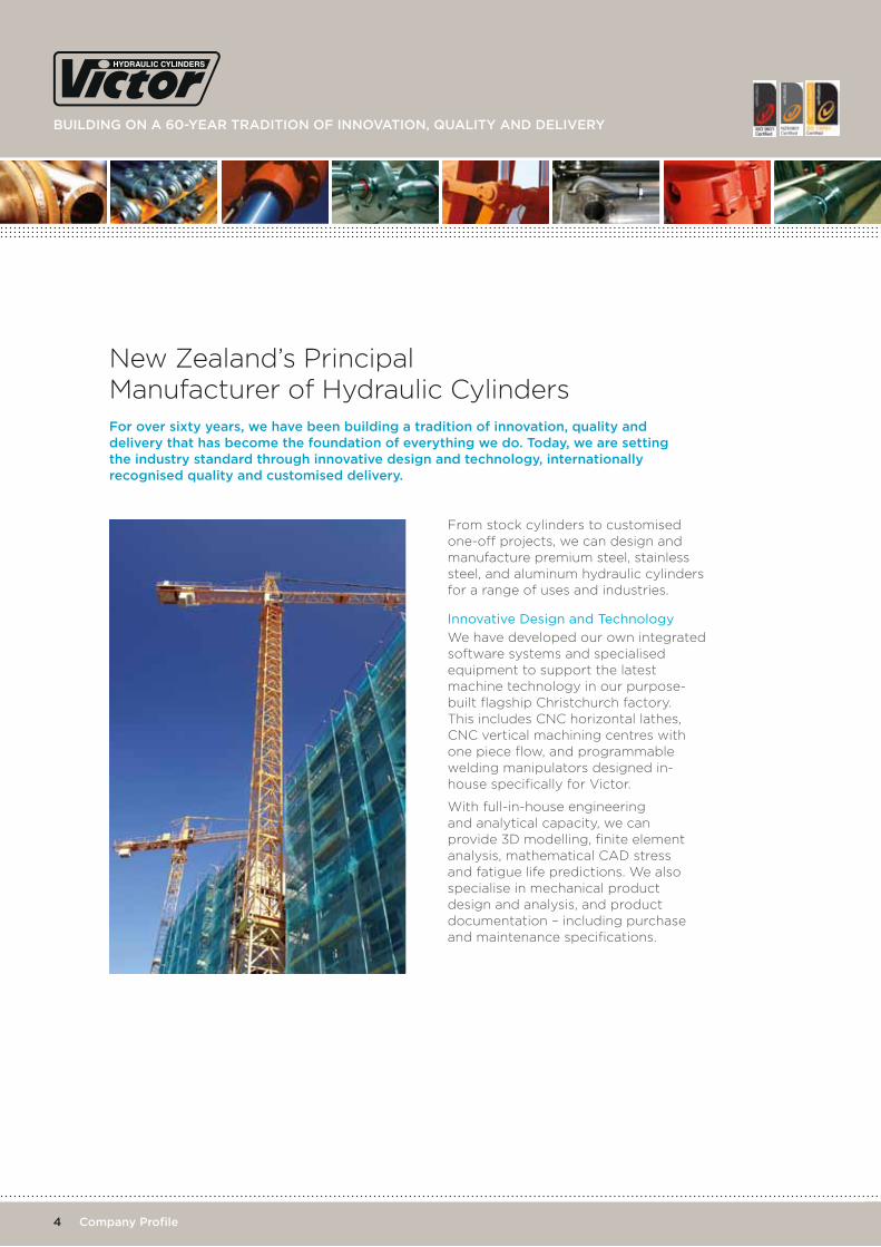
for over sixty years, we have been building a tradition of innovation, quality and delivery that has become the foundation of everything we do. today, we are setting the industry standard through innovative design and technology, internationally recognised quality and customised delivery.
From stock cylinders to customised one-off projects, we can design and manufacture premium steel, stainless steel, and aluminum hydraulic cylinders for a range of uses and industries.
innovative Design and technology
We have developed our own integrated software systems and specialised equipment to support the latest machine technology in our purpose-built flagship Christchurch factory. This includes CNC horizontal lathes, CNC vertical machining centres with one piece flow, and programmable welding manipulators designed in-house specifically for Victor.
With full-in-house engineering and analytical capacity, we can provide 3D modelling, finite element analysis, mathematical CAD stress and fatigue life predictions. We also specialise in mechanical product design and analysis, and product documentation – including purchase and maintenance specifications.
New Zealand’s Principal Manufacturer of Hydraulic Cylinders
viCtor teChniCal Catalogue
t +64 3 344 2700 e [email protected] | viCtor.Co.nZ5 Company profile
We have a full range of hydraulic cylinders currently in stock and available for immediate delivery.
With a wide variety of cylinder specifications and sizes, stock cylinders are a cost-effective option for your next project. We can also arrange long-term supply agreements, with consistency of supply.
This catalogue showcases some of the range of hydraulic cylinders generally held in stock. For more information and pricing – or to discuss a customised option – please contact us.
Whatever your project, we can supply the solution.
From one-off customised cylinders to project-based designs, or an OEM-specific application, we can provide the solution that will best suit your project specifications and requirements – in fact, application-specific custom- built cylinders represent over 90% of what we do.
We stock – and can source – a variety of materials for the manufacture of hydraulic cylinders for demanding applications and environments. Choose from a comprehensive range of various grades of stainless steel, aluminium and cylinder rod materials, with high performance finish coatings.
We also specialise in collaborative engineering. As an extension of your product and development team, we can provide input at a level that meets your company’s needs – from concept to product release, or any part of the process.
We support a diverse range of industries, including agriculture, construction, container handling, forestry, marine, mining and transportation industries.
We also have experience working on a wide variety of projects – from mobile hydraulic platforms, elevated work platforms and cargo handling grabs, to superyachts, a marine mineral sampling tool and even a 64-seater spacecraft simulator.
With dedicated design and engineering staff, we can work with your team to design, develop and manufacture the best solution for your requirements.
Stock Cylinders
Customised Cylinders
Building on a 60-year tradition of innovation, quality and delivery
6 Company profile
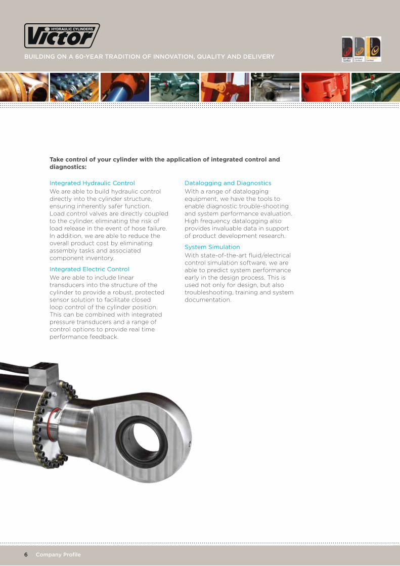
integrated Hydraulic control
We are able to build hydraulic control directly into the cylinder structure, ensuring inherently safer function. Load control valves are directly coupled to the cylinder, eliminating the risk of load release in the event of hose failure. In addition, we are able to reduce the overall product cost by eliminating assembly tasks and associated component inventory.
integrated Electric control
We are able to include linear transducers into the structure of the cylinder to provide a robust, protected sensor solution to facilitate closed loop control of the cylinder position. This can be combined with integrated pressure transducers and a range of control options to provide real time performance feedback.
Datalogging and Diagnostics
With a range of datalogging equipment, we have the tools to enable diagnostic trouble-shooting and system performance evaluation. High frequency datalogging also provides invaluable data in support of product development research.
System Simulation
With state-of-the-art fluid/electrical control simulation software, we are able to predict system performance early in the design process. This is used not only for design, but also troubleshooting, training and system documentation.
Take control of your cylinder with the application of integrated control and diagnostics:
viCtor teChniCal Catalogue
t +64 3 344 2700 e [email protected] | viCtor.Co.nZ7 Company profile
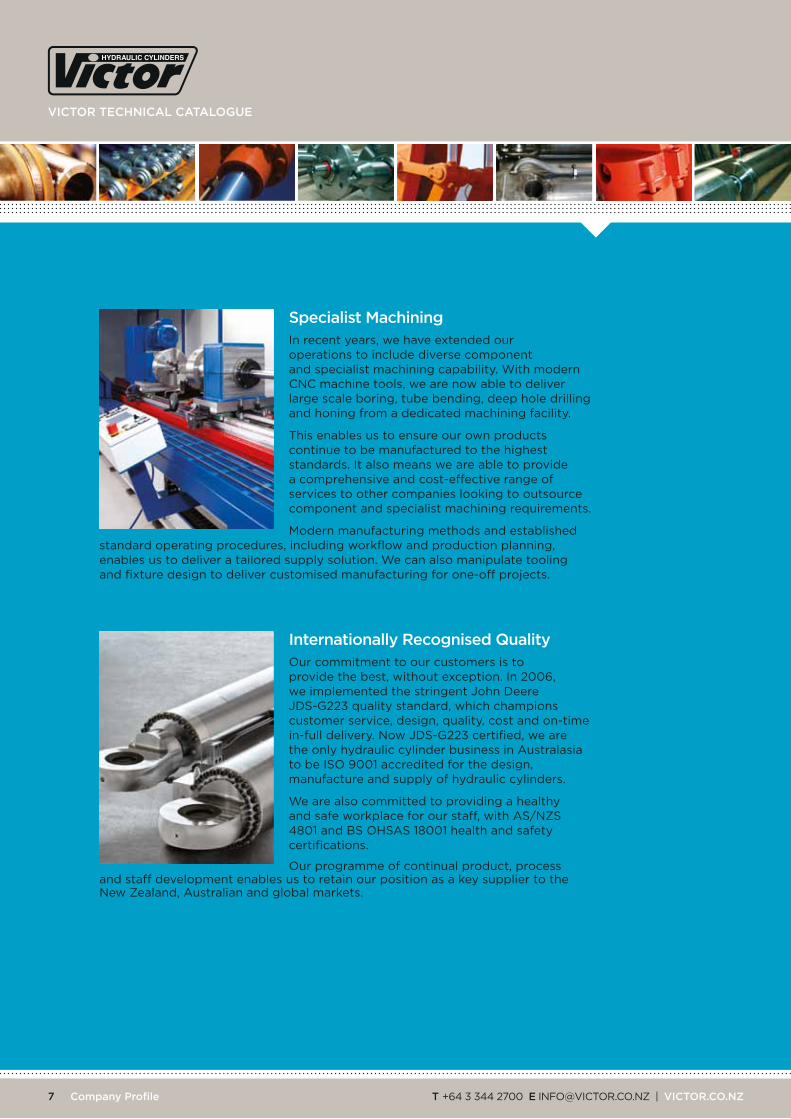
Specialist machining in recent years, we have extended our operations to include diverse component and specialist machining capability. With modern cnc machine tools, we are now able to deliver large scale boring, tube bending, deep hole drilling and honing from a dedicated machining facility.
this enables us to ensure our own products continue to be manufactured to the highest standards. it also means we are able to provide a comprehensive and cost-effective range of services to other companies looking to outsource component and specialist machining requirements.
Modern manufacturing methods and established standard operating procedures, including workflow and production planning, enables us to deliver a tailored supply solution. We can also manipulate tooling and fixture design to deliver customised manufacturing for one-off projects.
internationally recognised qualityour commitment to our customers is to provide the best, without exception. in 2006, we implemented the stringent John Deere JDS-G223 quality standard, which champions customer service, design, quality, cost and on-time in-full delivery. now JDS-G223 certified, we are the only hydraulic cylinder business in Australasia to be iSo 9001 accredited for the design, manufacture and supply of hydraulic cylinders.
We are also committed to providing a healthy and safe workplace for our staff, with AS/nzS 4801 and BS oHSAS 18001 health and safety certifications.
our programme of continual product, process and staff development enables us to retain our position as a key supplier to the new zealand, Australian and global markets.
Building on a 60-year tradition of innovation, quality and delivery
8 Company profile
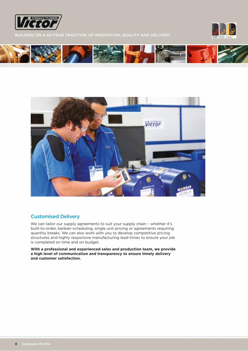
Customised delivery
We can tailor our supply agreements to suit your supply chain – whether it’s built-to-order, kanban scheduling, single unit pricing or agreements requiring quantity breaks. We can also work with you to develop competitive pricing structures and highly responsive manufacturing lead-times to ensure your job is completed on time and on budget.
With a professional and experienced sales and production team, we provide a high level of communication and transparency to ensure timely delivery and customer satisfaction.
viCtor teChniCal Catalogue
t +64 3 344 2700 e [email protected] | viCtor.Co.nZ9 Company profile
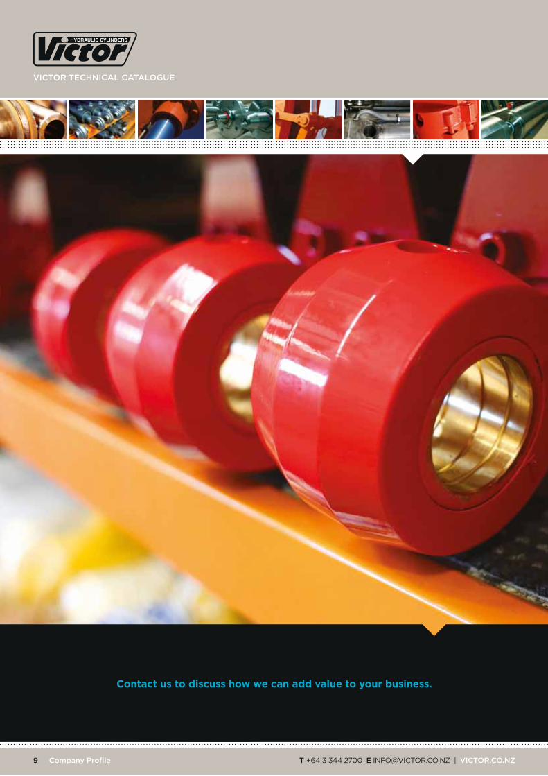
Contact us to discuss how we can add value to your business.
Building on a 60-year tradition of innovation, quality and delivery
10 Compact S two year warranty on all victor cylinders
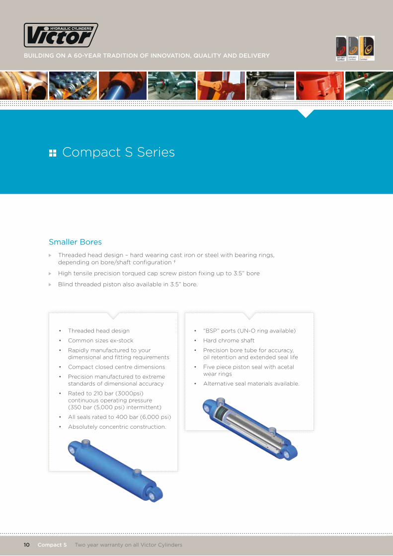
Smaller Bores
Threaded head design – hard wearing cast iron or steel with bearing rings, depending on bore/shaft configuration †
High tensile precision torqued cap screw piston fixing up to 3.5” bore
Blind threaded piston also available in 3.5” bore.
• Threaded head design
• Common sizes ex-stock
• Rapidly manufactured to your dimensional and fitting requirements
• Compact closed centre dimensions
• Precision manufactured to extreme standards of dimensional accuracy
• Rated to 210 bar (3000psi) continuous operating pressure (350 bar (5,000 psi) intermittent)
• All seals rated to 400 bar (6,000 psi)
• Absolutely concentric construction.
• “BSP” ports (UN-O ring available)
• Hard chrome shaft
• Precision bore tube for accuracy, oil retention and extended seal life
• Five piece piston seal with acetal wear rings
• Alternative seal materials available.
Compact S Series

viCtor teChniCal Catalogue
t +64 3 344 2700 e [email protected] | viCtor.Co.nZ
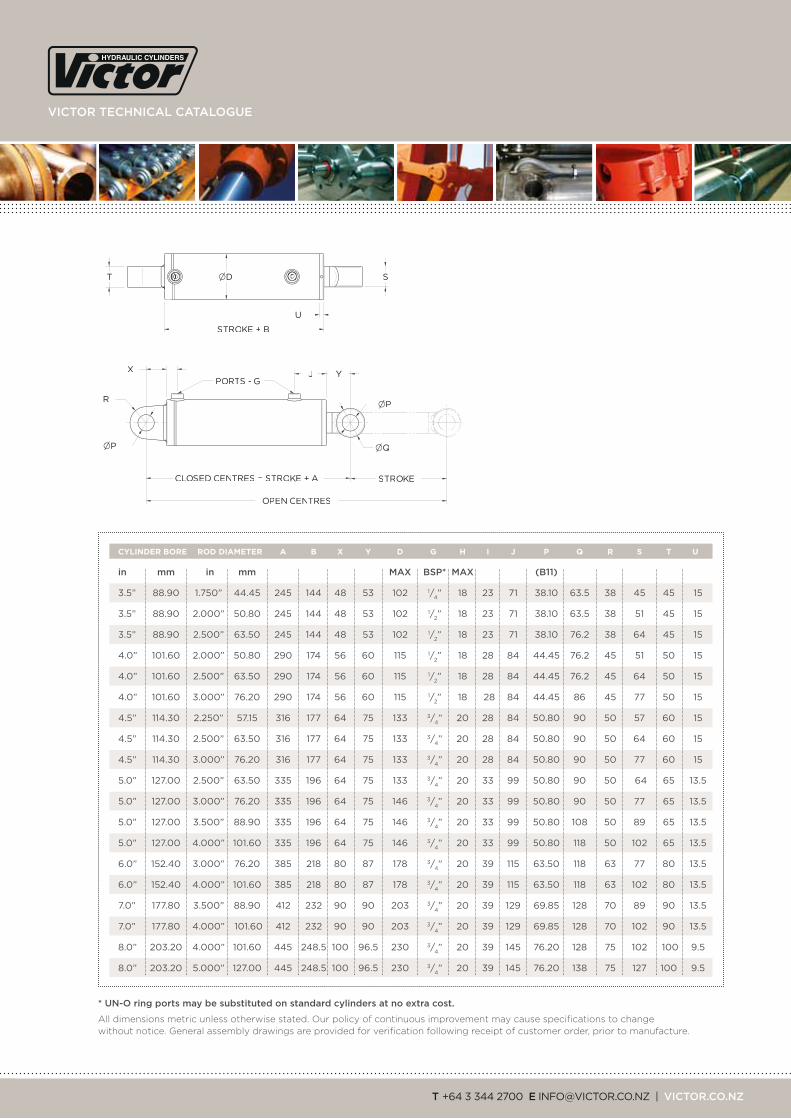
CLOSED CENTRES = STROKE + A STROKE
OPEN CENTRES
S ØD
STROKE + B
U
I J Y
ØP
ØP
ØQ
PORTS - G X
H
T
R
in mm in mm maX BSp* maX (B11)
1.5” 38.10 0.750” 19.05 143 91 24 28 50.8 1/4” 12 11 43 15.88 32 16 19 20 10
1.5” 38.10 1.000” 25.40 143 91 24 28 50.8 1/4” 12 11 43 15.88 32 16 25.4 20 10
2.0” 50.80 1.000” 25.40 170 107 28 35 63.5 3/8” 15 16 49 22.23 38 22 25.4 25 12
2.0” 50.80 1.250” 31.75 170 107 28 35 63.5 3/8” 15 16 49 22.23 38 22 32 25 12
2.0” † 50.80 1.500” 38.10 195 129 28 38 63.5 3/8” 15 16 71 22.23 45 22 38.1 25 34
2.5” 63.50 1.250” 31.75 195 121 32 42 76.2 1/2” 18 19 58 25.40 45 25 32 32 15
2.5” 63.50 1.375” 34.92 195 121 32 42 76.2 1/2” 18 19 58 25.40 45 25 35 32 15
2.5” 63.50 1.500” 38.10 195 121 32 42 76.2 1/2” 18 19 58 25.40 45 25 38.1 32 15
2.5” 63.50 1.750” 44.45 195 121 32 42 76.2 1/2” 18 19 58 25.40 51 25 45 32 15
2.5” † 63.50 2.000” 50.80 226 143 32 51 76.2 1/2” 18 19 81 25.40 63.5 25 51 32 37
3.0” 76.20 1.500” 38.10 220 132 40 48 88.9 1/2” 18 21 61 31.75 51 32 38.1 40 15
3.0” 76.20 1.750” 44.45 220 132 40 48 88.9 1/2” 18 21 61 31.75 51 32 45 40 15
3.0” 76.20 2.000” 50.80 220 132 40 48 88.9 1/2” 18 21 61 31.75 63.5 32 51 40 15
3.0” † 76.20 2.250” 57.15 247 154 40 53 88.9 1/2” 18 21 83 31.75 63.5 32 57 40 37
3.0” † 76.20 2.500” 63.50 247 154 40 53 88.9 1/2” 18 21 83 31.75 76.2 32 64 40 37
3.5” † 88.90 1.750” 44.45 245 144 48 53 102 1/2” 18 23 71 38.10 63.5 38 45 45 15
3.5” † 88.90 2.000” 50.80 245 144 48 53 102 1/2” 18 23 71 38.10 63.5 38 51 45 15
3.5” † 88.90 2.500” 63.50 245 144 48 53 102 1/2” 18 23 71 38.10 76.2 38 64 45 15
CYLINDER BORE ROD DIAMETER A B X Y D G H I J P Q R S T U
* un-o ring ports may be substituted on standard cylinders at no extra cost. † Steel head with bearing rings.
All dimensions metric unless otherwise stated. Our policy of continuous improvement may cause specifications to change without notice. General assembly drawings are provided for verification following receipt of customer order, prior to manufacture.

Building on a 60-year tradition of innovation, quality and delivery
12 Compact S two year warranty on all victor cylinders
3.5” and Larger Bores
Threaded steel head
Blind threaded piston locked with nylon ring
Replaceable heavy duty glass reinforced bearing rings
10”, 12” and larger bore cylinders also available on request.
• Threaded head and piston design
• Common sizes ex-stock
• Rapidly manufactured to your dimensional and fitting requirements
• Compact closed centre dimensions
• Precision manufactured to extreme standards of dimensional accuracy
• Rated to 210 bar (3000psi) continuous operating pressure (350 bar (5,000 psi) intermittent)
• All seals rated to 400 bar (6,000 psi)
• Absolutely concentric construction.
• “BSP” ports (UN-O ring available)
• Hard chrome shaft
• Precision bore tube for accuracy, oil retention and extended seal life
• Five piece piston seal with acetal wear rings
• Alternative seal materials available.
Compact S Series
viCtor teChniCal Catalogue
t +64 3 344 2700 e [email protected] | viCtor.Co.nZ
STROKECLOSED CENTRES = STROKE + A
SD
STROKE + B
U
J Y
P
Q
PORTS - G
P
X I
OPEN CENTRES
T
R
FORESTRY
in mm in mm maX BSp* maX (B11)
3.5” 88.90 1.750” 44.45 245 144 48 53 102 1/4” 18 23 71 38.10 63.5 38 45 45 15
3.5” 88.90 2.000” 50.80 245 144 48 53 102 1/2” 18 23 71 38.10 63.5 38 51 45 15
3.5” 88.90 2.500” 63.50 245 144 48 53 102 1/2” 18 23 71 38.10 76.2 38 64 45 15
4.0” 101.60 2.000” 50.80 290 174 56 60 115 1/2” 18 28 84 44.45 76.2 45 51 50 15
4.0” 101.60 2.500” 63.50 290 174 56 60 115 1/2” 18 28 84 44.45 76.2 45 64 50 15
4.0” 101.60 3.000” 76.20 290 174 56 60 115 1/2” 18 28 84 44.45 86 45 77 50 15
4.5” 114.30 2.250” 57.15 316 177 64 75 133 3/4” 20 28 84 50.80 90 50 57 60 15
4.5” 114.30 2.500” 63.50 316 177 64 75 133 3/4” 20 28 84 50.80 90 50 64 60 15
4.5” 114.30 3.000” 76.20 316 177 64 75 133 3/4” 20 28 84 50.80 90 50 77 60 15
5.0” 127.00 2.500” 63.50 335 196 64 75 133 3/4” 20 33 99 50.80 90 50 64 65 13.5
5.0” 127.00 3.000” 76.20 335 196 64 75 146 3/4” 20 33 99 50.80 90 50 77 65 13.5
5.0” 127.00 3.500” 88.90 335 196 64 75 146 3/4” 20 33 99 50.80 108 50 89 65 13.5
5.0” 127.00 4.000” 101.60 335 196 64 75 146 3/4” 20 33 99 50.80 118 50 102 65 13.5
6.0” 152.40 3.000” 76.20 385 218 80 87 178 3/4” 20 39 115 63.50 118 63 77 80 13.5
6.0” 152.40 4.000” 101.60 385 218 80 87 178 3/4” 20 39 115 63.50 118 63 102 80 13.5
7.0” 177.80 3.500” 88.90 412 232 90 90 203 3/4” 20 39 129 69.85 128 70 89 90 13.5
7.0” 177.80 4.000” 101.60 412 232 90 90 203 3/4” 20 39 129 69.85 128 70 102 90 13.5
8.0” 203.20 4.000” 101.60 445 248.5 100 96.5 230 3/4” 20 39 145 76.20 128 75 102 100 9.5
8.0” 203.20 5.000” 127.00 445 248.5 100 96.5 230 3/4” 20 39 145 76.20 138 75 127 100 9.5
CYLINDER BORE ROD DIAMETER A B X Y D G H I J P Q R S T U
* un-o ring ports may be substituted on standard cylinders at no extra cost.
All dimensions metric unless otherwise stated. Our policy of continuous improvement may cause specifications to change without notice. General assembly drawings are provided for verification following receipt of customer order, prior to manufacture.

Building on a 60-year tradition of innovation, quality and delivery
14 Compact Super S two year warranty on all victor cylinders
Threaded head design – hard wearing cast iron or steel with bearing rings, depending on bore/shaft configuration †
High tensile precision torqued cap screw piston fixing up to 3.5” bore
Blind threaded piston locked with nylon ring from 3.5” bore
Compact SUPER S styles are available for larger bore cylinders.
• Threaded head and piston design
• Common sizes ex-stock
• Fits where space is a real problem
• Rapidly manufactured to your dimensional and fitting requirements
• Super compact closed centre dimensions
• Precision manufactured to extreme standards of dimensional accuracy
• Rated to 210 bar (3000psi) continuous operating pressure (350 bar (5,000 psi) intermittent)
• All seals rated to 400 bar (6,000 psi)
• Absolutely concentric construction.
• “BSP” ports (UN-O ring available)
• Precision bore tube for accuracy, oil retention and extended seal life
• Hard chrome shaft
• Five piece piston seal with acetal wear rings
• Slug base.
Compact Super S Series

viCtor teChniCal Catalogue
t +64 3 344 2700 e [email protected] | viCtor.Co.nZ
CLOSED CENTRES = STROKE + A STROKE
OPEN CENTRES
S
STROKE + B U
I J Y
P
P
Q
PORTS - G
D
H
in mm in mm maX BSp* maX (B11)
1.5” 38.10 0.750” 19.05 123 116 24 50.8 1/4” 12 36 43 15.88 32 19 10
1.5” 38.10 1.000” 25.40 123 116 24 50.8 1/4” 12 36 43 15.88 32 25.4 10
2.0” 50.80 1.000” 25.40 147 141 28 63.5 3/8” 15 50 49 22.23 38 25.4 12
2.0” 50.80 1.250” 31.75 147 141 28 63.5 3/8” 15 50 49 22.23 38 32 12
2.0” † 50.80 1.500” 38.10 173 163 32 63.5 3/8” 15 50 71 22.23 45 38.1 34
2.5” 63.50 1.250” 31.75 170 159 36 76.2 1/2” 18 57 58 25.40 45 32 15
2.5” 63.50 1.375” 34.92 170 159 36 76.2 1/2” 18 57 58 25.40 45 35 15
2.5” 63.50 1.500” 38.10 170 159 36 76.2 1/2” 18 57 58 25.40 45 38.1 15
2.5” 63.50 1.750” 44.45 170 159 36 76.2 1/2” 18 57 58 25.40 51 45 15
2.5” † 63.50 2.000” 50.80 202 181 46 76.2 1/2” 18 57 81 25.40 63.5 51 37
3.0” 76.20 1.500” 38.10 190 180 42 88.9 1/2” 18 69 61 31.75 51 38.1 15
3.0” 76.20 1.750” 44.45 190 180 42 88.9 1/2” 18 69 61 31.75 51 45 15
3.0” 76.20 2.000” 50.80 190 180 42 88.9 1/2” 18 69 61 31.75 63.5 51 15
3.0” † 76.20 2.250” 57.15 225 202 55 88.9 1/2” 18 69 83 31.75 63.5 57 37
3.0” † 76.20 2.500” 63.50 225 202 55 88.9 1/2” 18 69 83 31.75 76.2 64 37
3.5” † 88.90 1.750” 44.45 213 200 51 102 1/2” 18 79 71 38.10 63.5 45 15
3.5” † 88.90 2.000” 50.80 213 200 51 102 1/2” 18 79 71 38.10 63.5 51 15
3.5” † 88.90 2.500” 63.50 213 200 51 102 1/2” 18 79 71 38.10 76.2 64 15
4.0” † 101.60 2.000” 50.80 254 241 58 115 1/2” 18 95 84 44.45 76.2 51 15
4.0” † 101.60 2.500” 63.50 254 241 58 115 1/2” 18 95 84 44.45 76.2 64 15
4.0” † 101.60 3.000” 76.20 254 241 58 115 1/2” 18 95 84 44.45 86 77 15
CYLINDER BORE ROD DIAMETER A B Y D G H I J P Q S U
* un-o ring ports may be substituted on standard cylinders at no extra cost. † Steel head with bearing rings.
All dimensions metric unless otherwise stated. Our policy of continuous improvement may cause specifications to change without notice. General assembly drawings are provided for verification following receipt of customer order, prior to manufacture.

Building on a 60-year tradition of innovation, quality and delivery
16 Compact marine two year warranty on all victor cylinders
‘2205’ stainless steel shaft and shaft eye
Stainless steel head (up to 3.0” bores)
Exterior sand blasted and arc zinc or aluminium sprayed
Plated steel head (3.5” bores and over)
Replaceable PTFE or glass reinforced nylon bearing rings
High tensile precision torqued cap screw piston fixing up to 3.5” bores
Blind threaded piston locked with nylon ring (3.5” bores and over).
• Threaded head design
• Compact closed centre dimensions
• Precision manufactured to extreme standards of dimensional accuracy
• Rapidly manufactured from stock components to your dimensional and fitting requirements
• Rated to 210 bar (3,000 psi) continuous operating pressure (350 bar (5,000 psi) intermittent)
• All seals rated to 400 bar (6,000 psi)
• Absolutely concentric construction.
• ‘2205’ stainless steel shaft eye
• Replaceable bearing rings
• Stainless steel threaded head (plated steel for 3.5” bores and over)
• Precision bore tube for accuracy, oil retention and extended seal life
• Sand blasted and arc sprayed zinc or aluminium
• ‘2205’ centreless ground stainless steel shaft
• Five piece piston seal with acetal wear rings
• Threaded piston connection
• “BSP” ports (UN-O ring available).
Compact Marine Series

viCtor teChniCal Catalogue
t +64 3 344 2700 e [email protected] | viCtor.Co.nZ
CCLLOOSSEEDD CCEENNTTRREESS == SSTTRROOKKEE ++ AA SSTTRROOKKEE
OOPPEENN CCEENNTTRREESS
SS DD
SSTTRROOKKEE ++ BB
UU
II JJ YY
PP
PP
PPOORRTTSS -- GG XX
HH
TT
RR
in mm in mm maX BSp* maX (B11)
1.5” 38.10 0.750” 19.05 143 91 24 28 50.8 1/4” 12 11 43 15.88 32 16 19 20 10
1.5” 38.10 1.000” 25.40 143 91 24 28 50.8 1/4” 12 11 43 15.88 32 16 25.4 20 10
2.0” 50.80 1.000” 25.40 170 107 28 35 63.5 3/8” 15 16 49 22.23 38 22 25.4 25 12
2.0” 50.80 1.250” 31.75 170 107 28 35 63.5 3/8” 15 16 49 22.23 38 22 32 25 12
2.5” 63.50 1.250” 31.75 195 121 32 42 76.2 1/2” 18 19 58 25.40 45 25 32 32 15
2.5” 63.50 1.500” 38.10 195 121 32 42 76.2 1/2” 18 19 58 25.40 45 25 38.1 32 15
2.5” 63.50 1.750” 44.45 195 121 32 42 76.2 1/2” 18 19 58 25.40 51 25 45 32 15
3.0” 76.20 1.500” 38.10 220 132 40 48 88.9 1/2” 18 21 61 31.75 51 32 38.1 40 15
3.0” 76.20 1.750” 44.45 220 132 40 48 88.9 1/2” 18 21 61 31.75 51 32 45 40 15
3.0” 76.20 2.000” 50.80 220 132 40 48 88.9 1/2” 18 21 61 31.75 63.5 32 51 40 15
3.5” 88.90 1.750” 44.45 245 144 48 53 102 1/2” 18 23 71 38.10 63.5 38 45 45 15
3.5” 88.90 2.000” 50.80 245 144 48 53 102 1/2” 18 23 71 38.10 63.5 38 51 45 15
4.0” 101.60 2.000” 50.80 290 174 56 60 115 1/2” 18 28 84 44.45 76.2 45 51 50 15
4.0” 101.60 2.500” 63.50 290 174 56 60 115 1/2” 18 28 84 44.45 76.2 45 64 50 15
CYLINDER BORE ROD DIAMETER A B X Y D G H I J P Q R S T U
* un-o ring ports may be substituted on standard cylinders at no extra cost.
All dimensions metric unless otherwise stated. Our policy of continuous improvement may cause specifications to change without notice. General assembly drawings are provided for verification following receipt of customer order, prior to manufacture.
All compact Series options available in compact Marine

Building on a 60-year tradition of innovation, quality and delivery
18 Compact top link two year warranty on all victor cylinders
Extended base for increased clearance
Common sizes ex-stock
High tensile precision torqued cap screw piston fixing
Rated to 210 bar (3,000 psi) continuous operating pressure (350 bar (5,000 psi) intermittent)
All seals rated to 400 bar (6,000 psi).
• CAT 2 or 3 ball end
• Precision bore tube for accuracy, oil retention and extended seal life
• Hard chrome shaft
• Five piece piston seal with acetal wear rings
• Cap screwed piston connection
• “BSP” ports (UN-O ring available).
Compact Top Link Series
viCtor teChniCal Catalogue
t +64 3 344 2700 e [email protected] | viCtor.Co.nZ
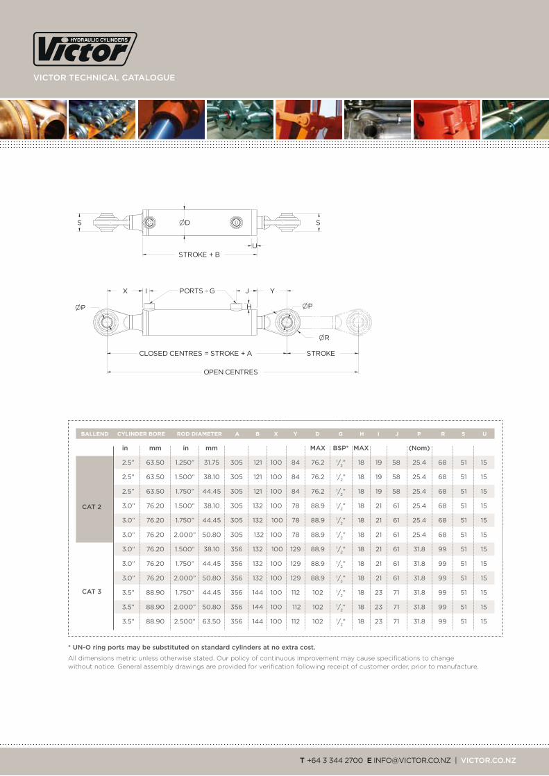
CLOSED CENTRES = STROKE + A STROKE
OPEN CENTRES
S
STROKE + B U
I J Y
P P
R
PORTS - G X
D S
H
in mm in mm maX BSp* maX (nom)
2.5” 63.50 1.250” 31.75 305 121 100 84 76.2 1/2” 18 19 58 25.4 68 51 15
2.5” 63.50 1.500” 38.10 305 121 100 84 76.2 1/2” 18 19 58 25.4 68 51 15
2.5” 63.50 1.750” 44.45 305 121 100 84 76.2 1/2” 18 19 58 25.4 68 51 15
3.0” 76.20 1.500” 38.10 305 132 100 78 88.9 1/2” 18 21 61 25.4 68 51 15
3.0” 76.20 1.750” 44.45 305 132 100 78 88.9 1/2” 18 21 61 25.4 68 51 15
3.0” 76.20 2.000” 50.80 305 132 100 78 88.9 1/2” 18 21 61 25.4 68 51 15
3.0” 76.20 1.500” 38.10 356 132 100 129 88.9 1/2” 18 21 61 31.8 99 51 15
3.0” 76.20 1.750” 44.45 356 132 100 129 88.9 1/2” 18 21 61 31.8 99 51 15
3.0” 76.20 2.000” 50.80 356 132 100 129 88.9 1/2” 18 21 61 31.8 99 51 15
3.5” 88.90 1.750” 44.45 356 144 100 112 102 1/2” 18 23 71 31.8 99 51 15
3.5” 88.90 2.000” 50.80 356 144 100 112 102 1/2” 18 23 71 31.8 99 51 15
3.5” 88.90 2.500” 63.50 356 144 100 112 102 1/2” 18 23 71 31.8 99 51 15
CYLINDER BORE ROD DIAMETER A B X Y D G H I J P R S UBALLEND
* un-o ring ports may be substituted on standard cylinders at no extra cost.
All dimensions metric unless otherwise stated. Our policy of continuous improvement may cause specifications to change without notice. General assembly drawings are provided for verification following receipt of customer order, prior to manufacture.
Cat 2
Cat 3
Building on a 60-year tradition of innovation, quality and delivery
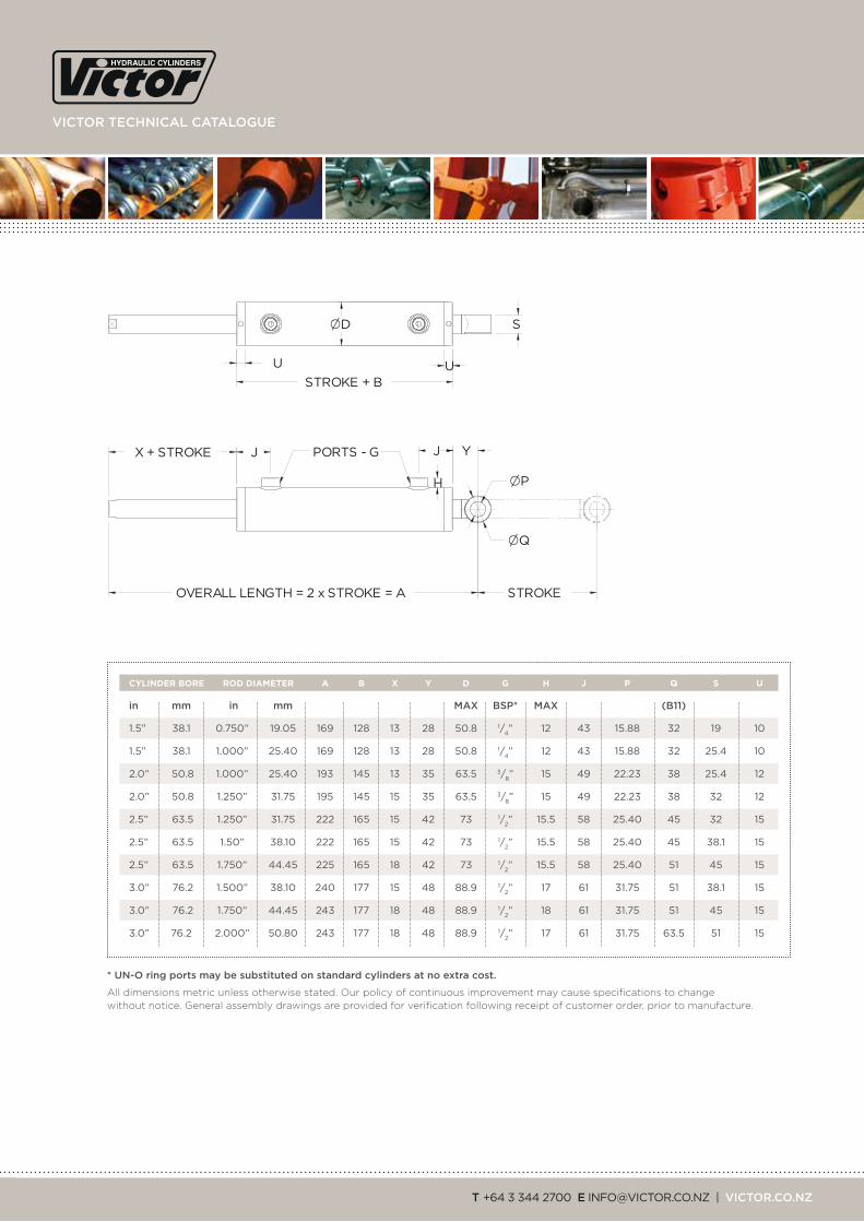
20 thru rod two year warranty on all victor cylinders
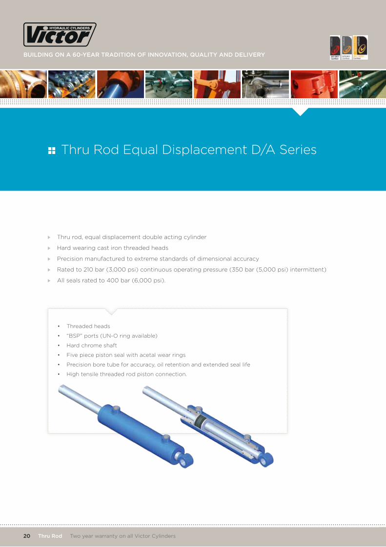
Thru rod, equal displacement double acting cylinder
Hard wearing cast iron threaded heads
Precision manufactured to extreme standards of dimensional accuracy
Rated to 210 bar (3,000 psi) continuous operating pressure (350 bar (5,000 psi) intermittent)
All seals rated to 400 bar (6,000 psi).
• Threaded heads
• “BSP” ports (UN-O ring available)
• Hard chrome shaft
• Five piece piston seal with acetal wear rings
• Precision bore tube for accuracy, oil retention and extended seal life
• High tensile threaded rod piston connection.
Thru Rod Equal Displacement D/A Series
viCtor teChniCal Catalogue
t +64 3 344 2700 e [email protected] | viCtor.Co.nZ
STROKEOVERALL LENGTH = 2 x STROKE = A
S D
STROKE + B U
J J Y
P
Q
PORTS - G
U
H
X + STROKE
* un-o ring ports may be substituted on standard cylinders at no extra cost.
All dimensions metric unless otherwise stated. Our policy of continuous improvement may cause specifications to change without notice. General assembly drawings are provided for verification following receipt of customer order, prior to manufacture.
in mm in mm maX BSp* maX (B11)
1.5” 38.1 0.750” 19.05 169 128 13 28 50.8 1/4” 12 43 15.88 32 19 10
1.5” 38.1 1.000” 25.40 169 128 13 28 50.8 1/4” 12 43 15.88 32 25.4 10
2.0” 50.8 1.000” 25.40 193 145 13 35 63.5 3/8” 15 49 22.23 38 25.4 12
2.0” 50.8 1.250” 31.75 195 145 15 35 63.5 3/8” 15 49 22.23 38 32 12
2.5” 63.5 1.250” 31.75 222 165 15 42 73 1/2” 15.5 58 25.40 45 32 15
2.5” 63.5 1.50” 38.10 222 165 15 42 73 1/2” 15.5 58 25.40 45 38.1 15
2.5” 63.5 1.750” 44.45 225 165 18 42 73 1/2” 15.5 58 25.40 51 45 15
3.0” 76.2 1.500” 38.10 240 177 15 48 88.9 1/2” 17 61 31.75 51 38.1 15
3.0” 76.2 1.750” 44.45 243 177 18 48 88.9 1/2” 18 61 31.75 51 45 15
3.0” 76.2 2.000” 50.80 243 177 18 48 88.9 1/2” 17 61 31.75 63.5 51 15
CYLINDER BORE ROD DIAMETER A B X Y D G H J P Q S U

Building on a 60-year tradition of innovation, quality and delivery
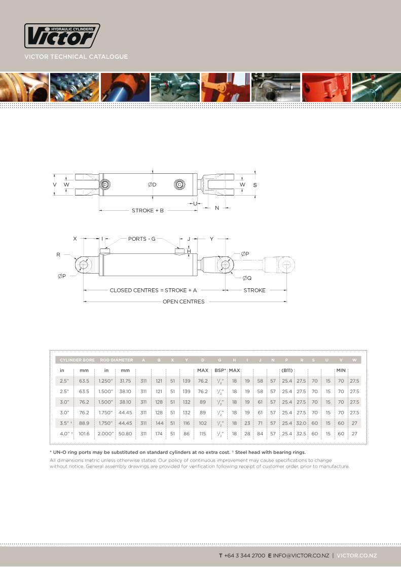
22 Compact S.a.e. two year warranty on all victor cylinders
Built to international S.A.E. J716 / ISO 2057 standards – gives full in-the field interchangeability
Threaded head design – hard wearing cast iron or steel with bearing rings, depending on bore/shaft configuration †
High tensile precision torqued cap screw piston fixing up to 3.5” bore
Blind threaded piston for 3.5” and 4.0” bores.
• Threaded head design
• Common S.A.E. sizes ex-stock
• Rapidly manufactured to your dimensional and fitting requirements
• Precision manufactured to extreme standards of dimensional accuracy
• Rated to 210 bar (3,000 psi) continuous operating pressure (350 bar (5,000 psi) intermittent)
• All seals rated to 400 bar (6,000 psi)
• Absolutely concentric construction.
• 1” pins & clips
• Threaded head
• Hard chrome shaft
• Precision bore tube for accuracy, oil retention and extended seal life
• “BSP” ports (UN-O ring available)
• Five piece piston seal with acetal wear rings
• Cap screwed piston connection.
Compact S.A.E Series
viCtor teChniCal Catalogue
t +64 3 344 2700 e [email protected] | viCtor.Co.nZ
CLOSED CENTRES = STROKE + A STROKE
OPEN CENTRES
D
STROKE + B U
I J Y
P
P
Q
PORTS - G X
W V W
N
H R
in mm in mm maX BSp* maX (B11) min
2.5” 63.5 1.250” 31.75 311 121 51 139 76.2 1/2” 18 19 58 57 25.4 27.5 70 15 70 27.5
2.5” 63.5 1.500” 38.10 311 121 51 139 76.2 1/2” 18 19 58 57 25.4 27.5 70 15 70 27.5
3.0” 76.2 1.500” 38.10 311 128 51 132 89 1/2” 18 19 61 57 25.4 27.5 70 15 70 27.5
3.0” 76.2 1.750” 44.45 311 128 51 132 89 1/2” 18 19 61 57 25.4 27.5 70 15 70 27.5
3.5” † 88.9 1.750” 44.45 311 144 51 116 102 1/2” 18 23 71 57 25.4 32.0 60 15 60 27
4.0” † 101.6 2.000” 50.80 311 174 51 86 115 1/2” 18 28 84 57 25.4 32.5 60 15 60 27
CYLINDER BORE ROD DIAMETER A B X Y D G H I J N P R S U V W
* un-o ring ports may be substituted on standard cylinders at no extra cost. † Steel head with bearing rings.
All dimensions metric unless otherwise stated. Our policy of continuous improvement may cause specifications to change without notice. General assembly drawings are provided for verification following receipt of customer order, prior to manufacture.
Building on a 60-year tradition of innovation, quality and delivery
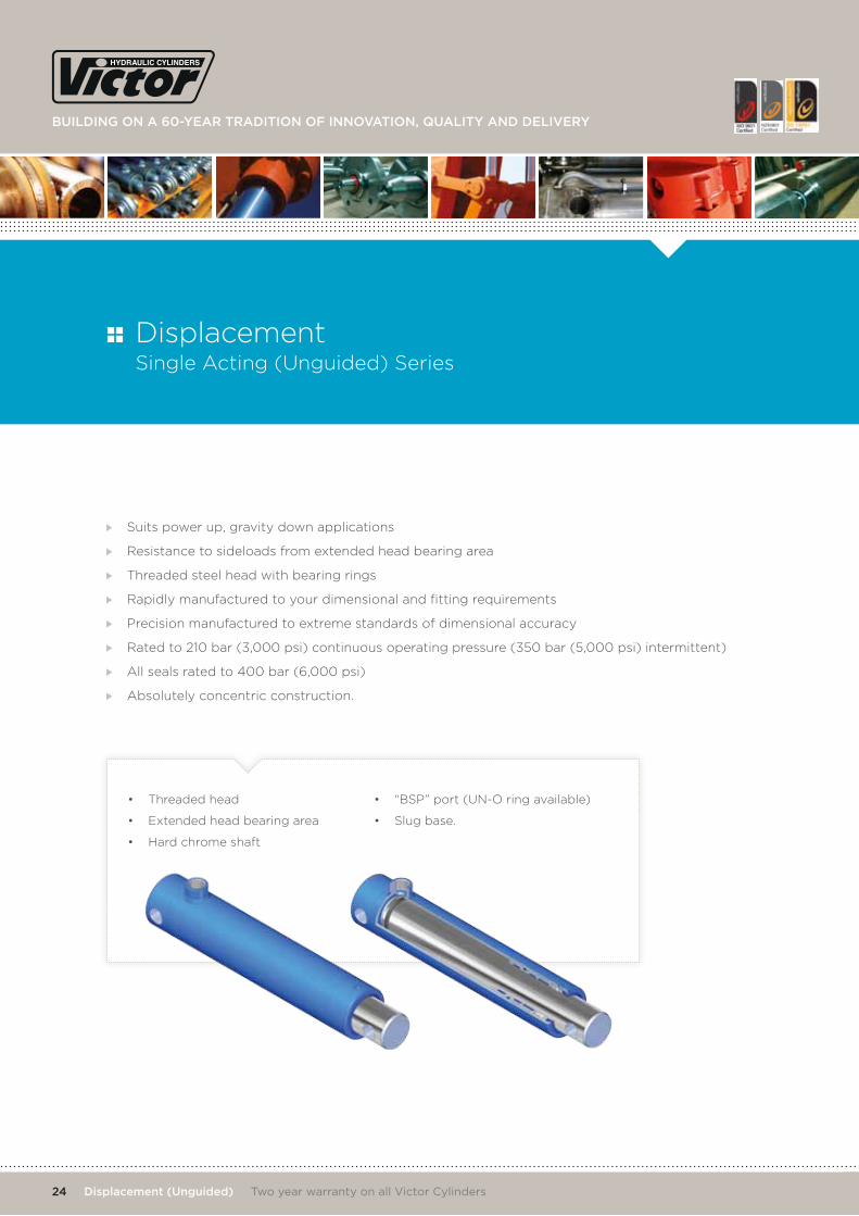
24 displacement (unguided) two year warranty on all victor cylinders
Suits power up, gravity down applications
Resistance to sideloads from extended head bearing area
Threaded steel head with bearing rings
Rapidly manufactured to your dimensional and fitting requirements
Precision manufactured to extreme standards of dimensional accuracy
Rated to 210 bar (3,000 psi) continuous operating pressure (350 bar (5,000 psi) intermittent)
All seals rated to 400 bar (6,000 psi)
Absolutely concentric construction.
• Threaded head
• Extended head bearing area
• Hard chrome shaft
• “BSP” port (UN-O ring available)
• Slug base.
Displacement Single Acting (Unguided) Series

viCtor teChniCal Catalogue
t +64 3 344 2700 e [email protected] | viCtor.Co.nZ
CLOSED CENTRES = STROKE + A STROKE
OPEN CENTRES
ROD DIA D
STROKE + B U
I Y
P P
PORTS - G W
H
* un-o ring ports may be substituted on standard cylinders at no extra cost.
All dimensions metric unless otherwise stated. Our policy of continuous improvement may cause specifications to change without notice. General assembly drawings are provided for verification following receipt of customer order, prior to manufacture.
in mm maX BSp* maX (B11)
1.500” 38.10 155 145 30 63.5 3/8” 15 53 19.05 34 20
1.750” 44.45 176 164 32 76.2 1/2” 18 58 22.23 37 25
2.000” 50.80 176 164 32 76.2 1/2” 18 58 22.23 37 25
2.500” 63.50 179 172 32 88.9 1/2” 18 63 25.40 37 25
ROD DIAMETER A B Y D G H I P U w
Building on a 60-year tradition of innovation, quality and delivery
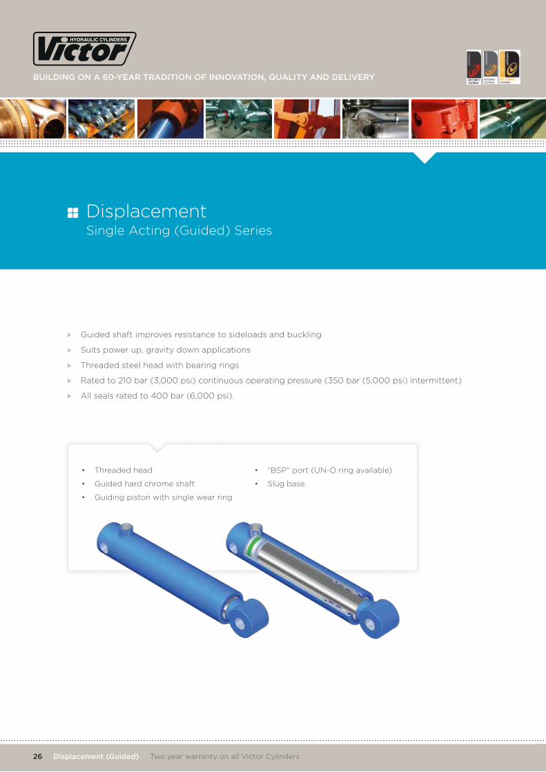
26 displacement (guided) two year warranty on all victor cylinders
Guided shaft improves resistance to sideloads and buckling
Suits power up, gravity down applications
Threaded steel head with bearing rings
Rated to 210 bar (3,000 psi) continuous operating pressure (350 bar (5,000 psi) intermittent)
All seals rated to 400 bar (6,000 psi).
• Threaded head
• Guided hard chrome shaft
• Guiding piston with single wear ring
• “BSP” port (UN-O ring available)
• Slug base.
Displacement Single Acting (Guided) Series
viCtor teChniCal Catalogue
t +64 3 344 2700 e [email protected] | viCtor.Co.nZ
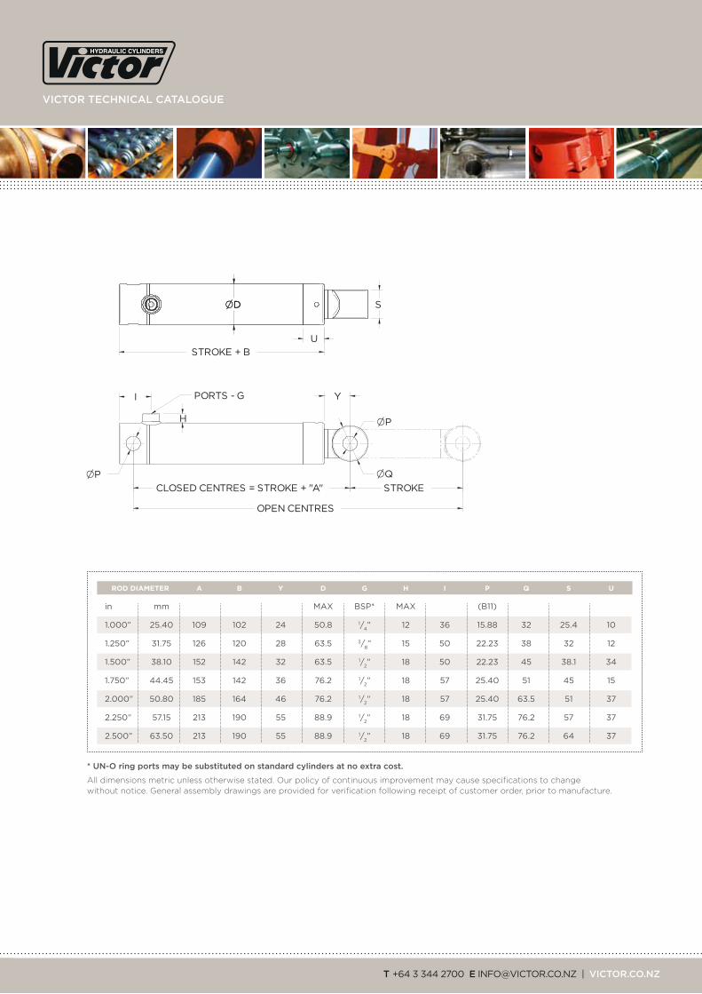
CLOSED CENTRES = STROKE + "A" STROKE
OPEN CENTRES
SDD
STROKE + B
U
I Y
P
P
Q
PORTS - G
H
* un-o ring ports may be substituted on standard cylinders at no extra cost.
All dimensions metric unless otherwise stated. Our policy of continuous improvement may cause specifications to change without notice. General assembly drawings are provided for verification following receipt of customer order, prior to manufacture.
in mm MAX BSP* MAX (B11)
1.000” 25.40 109 102 24 50.8 1/4” 12 36 15.88 32 25.4 10
1.250” 31.75 126 120 28 63.5 3/8” 15 50 22.23 38 32 12
1.500” 38.10 152 142 32 63.5 1/2” 18 50 22.23 45 38.1 34
1.750” 44.45 153 142 36 76.2 1/2” 18 57 25.40 51 45 15
2.000” 50.80 185 164 46 76.2 1/2” 18 57 25.40 63.5 51 37
2.250” 57.15 213 190 55 88.9 1/2” 18 69 31.75 76.2 57 37
2.500” 63.50 213 190 55 88.9 1/2” 18 69 31.75 76.2 64 37
ROD DIAMETER A B Y D G H I P Q S U
Building on a 60-year tradition of innovation, quality and delivery
28 phasing Cylinders two year warranty on all victor cylinders
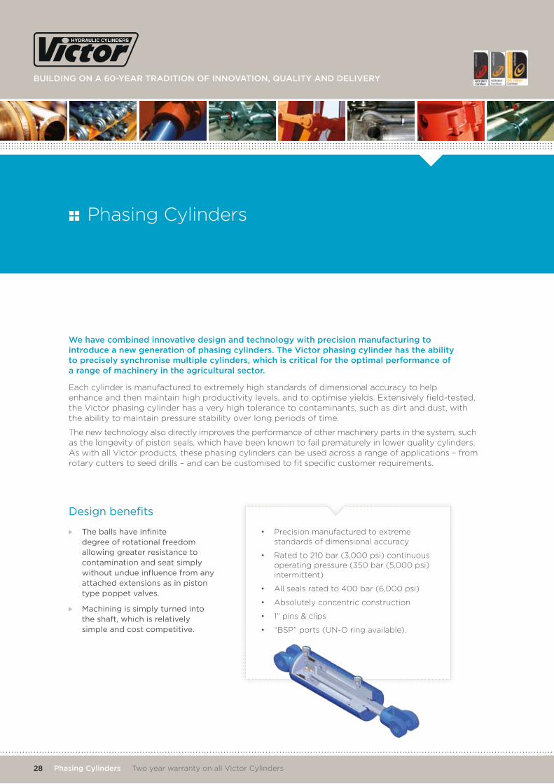
Design benefits
the balls have infinite degree of rotational freedom allowing greater resistance to contamination and seat simply without undue influence from any attached extensions as in piston type poppet valves.
Machining is simply turned into the shaft, which is relatively simple and cost competitive.
We have combined innovative design and technology with precision manufacturing to introduce a new generation of phasing cylinders. the victor phasing cylinder has the ability to precisely synchronise multiple cylinders, which is critical for the optimal performance of a range of machinery in the agricultural sector.
Each cylinder is manufactured to extremely high standards of dimensional accuracy to help enhance and then maintain high productivity levels, and to optimise yields. Extensively field-tested, the Victor phasing cylinder has a very high tolerance to contaminants, such as dirt and dust, with the ability to maintain pressure stability over long periods of time.
The new technology also directly improves the performance of other machinery parts in the system, such as the longevity of piston seals, which have been known to fail prematurely in lower quality cylinders. As with all Victor products, these phasing cylinders can be used across a range of applications – from rotary cutters to seed drills – and can be customised to fit specific customer requirements.
Phasing Cylinders
• Precision manufactured to extreme standards of dimensional accuracy
• Rated to 210 bar (3,000 psi) continuous operating pressure (350 bar (5,000 psi) intermittent)
• All seals rated to 400 bar (6,000 psi)
• Absolutely concentric construction
• 1” pins & clips
• “BSP” ports (UN-O ring available).
viCtor teChniCal Catalogue
t +64 3 344 2700 e [email protected] | viCtor.Co.nZ
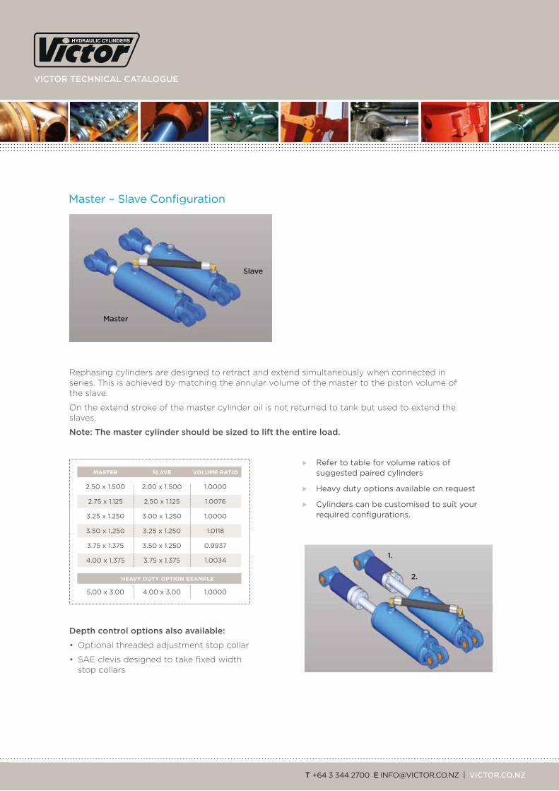
Master – Slave configuration
Rephasing cylinders are designed to retract and extend simultaneously when connected in series. This is achieved by matching the annular volume of the master to the piston volume of the slave.
On the extend stroke of the master cylinder oil is not returned to tank but used to extend the slaves.
note: the master cylinder should be sized to lift the entire load.
depth control options also available:
• Optional threaded adjustment stop collar
• SAE clevis designed to take fixed width stop collars
refer to table for volume ratios of suggested paired cylinders
Heavy duty options available on request
cylinders can be customised to suit your required configurations.
Slave
master
2.
1.
2.50 x 1.500 2.00 x 1.500 1.0000
2.75 x 1.125 2.50 x 1.125 1.0076
3.25 x 1.250 3.00 x 1.250 1.0000
3.50 x 1.250 3.25 x 1.250 1.0118
3.75 x 1.375 3.50 x 1.250 0.9937
4.00 x 1.375 3.75 x 1.375 1.0034
5.00 x 3.00 4.00 x 3.00 1.0000
MASTER SLAVE VOLUME RATIO
HEAVY DUTY OPTION EXAMPLE
Building on a 60-year tradition of innovation, quality and delivery
30 phasing Cylinders two year warranty on all victor cylinders
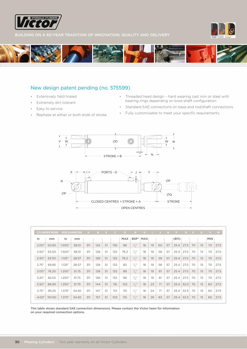
CLOSED CENTRES = STROKE + A STROKE
OPEN CENTRES
D
STROKE + B U
I J Y
P
P
Q
PORTS - G X
W V W
N
H R
• Extensively field trialed
• Extremely dirt tolerant
• Easy to service
• Rephase at either or both ends of stroke
• Threaded head design – hard wearing cast iron or steel with bearing rings depending on bore shaft configuration
• Standard SAE connections on base and rod/shaft connections
• Fully customisable to meet your specific requirements.
in mm in mm maX BSp* maX (B11) min
2.00” 50.80 1.500” 38.10 311 124 51 136 88 1/2” 18 19 60 57 25.4 27.5 70 15 70 27.5
2.50” 63.50 1.500” 38.10 311 128 51 132 76.2 1/2” 18 19 58 57 25.4 27.5 70 15 70 27.5
2.50” 63.50 1.125” 28.57 311 128 51 132 76.2 1/2” 18 19 58 57 25.4 27.5 70 15 70 27.5
2.75” 69.85 1.125” 28.57 311 128 51 132 83 1/2” 18 19 58 57 25.4 27.5 70 15 70 27.5
3.00” 76.20 1.250” 31.75 311 128 51 132 89 1/2” 18 19 61 57 25.4 27.5 70 15 70 27.5
3.25” 82.55 1.250” 31.75 311 128 51 132 96 1/2” 18 19 61 57 25.4 27.5 70 15 70 27.5
3.50” 88.90 1.250” 31.75 311 144 51 116 102 1/2” 18 23 71 57 25.4 32.0 70 15 60 27.5
3.75” 95.25 1.375” 34.92 311 147 51 113 115 1/2” 18 24 71 57 25.4 32.5 70 15 60 27.5
4.00” 101.60 1.375” 34.92 311 157 51 103 115 1/2” 18 26 83 57 25.4 32.5 70 15 60 27.5
CYLINDER BORE ROD DIAMETER A B X Y D G H I J N P R S U V W
new design patent pending (no. 575599)
this table shows standard Sae connection dimensions. please contact the victor team for information on your required connection options.

Building on a 60-year tradition of innovation, quality and delivery
B
D
A
C
A
P
PCD
C
E D
F P
in mm (f8)
1.5” 38.1 60 60 22.23 110 25
2.0” 50.8 75 75 25.40 126 32
2.5” 63.5 90 90 31.75 154 40
3.0” 76.2 110 110 38.10 186 50
3.5” 88.9 125 125 44.45 214 50
4.0” 101.6 140 140 50.80 242 60
4.5” 114.3 156 156 57.15 270 65
5.0” 127.0 170 170 63.50 297 80
6.0” 152.4 210 210 76.20 363 80
7.0” 177.8 243 243 88.90 420 100
8.0” 203.2 270 270 101.6 474 120
CYLINDER BORE A B C D WIDTH
in mm
1.5” 38.1 106 11 4 84 11
2.0” 50.8 128 13 4 101 11
2.5” 63.5 156 17 4 121 15
3.0” 76.2 176 17 4 141 19
3.5” 88.9 204 21 4 161 24
4.0” 101.6 217 21 4 174 30
4.5” 114.3 250 25 4 200 30
5.0” 127.0 270 25 6 218 30
6.0” 152.4 300 25 6 247 38
7.0” 177.8 360 31 6 295 48
8.0” 203.2 384 31 8 320 48
CYLINDER BORE A P HOLES PCD WIDTH
CYLINDER BORE A B C D WIDTH
in mm
1.5” 38.1 106 106 11 82 82 11
2.0” 50.8 128 128 13 100 100 11
2.5” 63.5 157 157 17 121 121 15
3.0” 76.2 177 177 17 141 141 19
3.5” 88.9 204 204 21 160 160 24
4.0” 101.6 216 216 21 172 172 30
CYLINDER BORE C D P E F WIDTH
trunnion Mount
flange Mount – Square
flange Mount – round
32 Cylinder options two year warranty on all victor cylinders
viCtor teChniCal Catalogue
t +64 3 344 2700 e [email protected] | viCtor.Co.nZ
W V
E
P
N
C
Y
W V
E
P
Y
N
C
X
E
P
W V
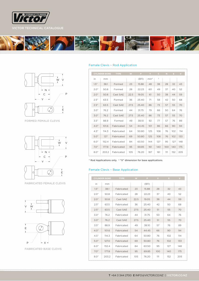
in mm (B11) min* †
1.5” 38.1 formed 23 15.88 48 38 28 32 43
2.0” 50.8 formed 28 22.23 60 49 37 40 52
2.0” 50.8 cast SAE 22.5 19.05 61 50 38 44 59
2.5” 63.5 formed 36 25.40 71 58 42 50 68
2.5” 63.5 cast SAE 27.5 25.40 86 73 57 55 70
3.0” 76.2 formed 44 31.75 79 66 50 64 76
3.0” 76.2 cast SAE 27.5 25.40 86 73 57 55 70
3.5” 88.9 formed 49 38.10 92 77 57 76 89
4.0” 101.6 fabricated 54 44.45 101 86 66 90 94
4.5” 114.3 fabricated 64 50.80 125 108 76 102 114
5.0” 127 fabricated 69 50.80 125 108 76 102 133
6.0” 152.4 fabricated 84 63.50 144 127 95 127 148
7.0” 177.8 fabricated 95 69.85 161 140 100 140 175
8.0” 203.2 fabricated 105 76.20 187 161 111 152 205
CYLINDER BORE TYPE W P Y C N E V
CYLINDER BORE TYPE W P X E V
female clevis – rod Application
female clevis – Base Application
* rod applications only. † “X” dimension for base applications.
formed female CleviS
faBriCated female CleviS
faBriCated BaSe CleviS
in mm (B11)
1.5” 38.1 fabricated 23 15.88 28 32 43
2.0” 50.8 fabricated 28 22.23 37 40 52
2.0” 50.8 cast SAE 22.5 19.05 38 44 59
2.5” 63.5 fabricated 36 25.40 42 50 68
2.5” 63.5 cast SAE 27.5 25.40 51 55 70
3.0” 76.2 fabricated 44 31.75 50 64 76
3.0” 76.2 cast SAE 27.5 25.40 51 55 70
3.5” 88.9 fabricated 49 38.10 57 76 89
4.0” 101.6 fabricated 54 44.45 66 90 94
4.5” 114.3 fabricated 64 50.80 76 102 114
5.0” 127.0 fabricated 69 50.80 76 102 133
6.0” 152.4 fabricated 84 63.50 95 127 148
7.0” 177.8 fabricated 95 69.85 100 140 175
8.0” 203.2 fabricated 105 76.20 111 152 205
Building on a 60-year tradition of innovation, quality and delivery
C
Y
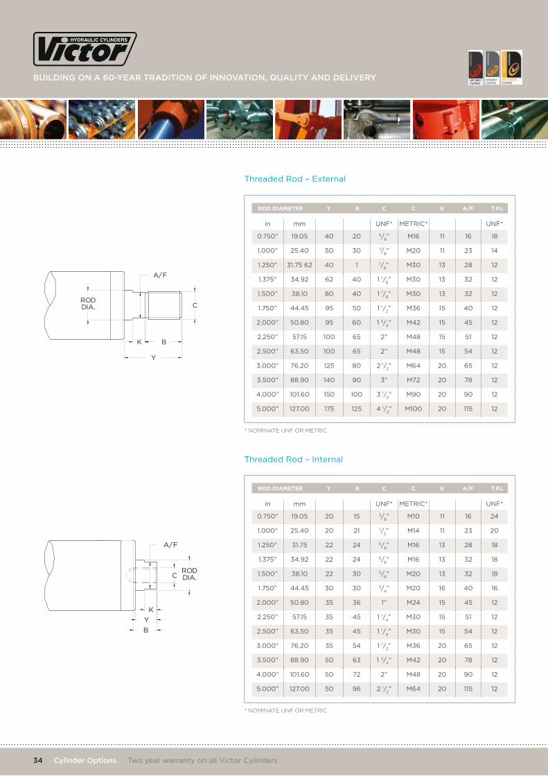
A/F
RODDIA.
K B
C
A/F
K
Y
B
RODDIA.
in mm Unf* MEtric* Unf*
0.750” 19.05 40 20 5/8” M16 11 16 18
1.000” 25.40 50 30 7/8” M20 11 23 14
1.250” 31.75 62 40 1 1/8” M30 13 28 12
1.375” 34.92 62 40 1 1/8” M30 13 32 12
1.500” 38.10 80 40 1 1/8” M30 13 32 12
1.750” 44.45 95 50 1 1/2” M36 15 40 12
2.000” 50.80 95 60 1 3/4” M42 15 45 12
2.250” 57.15 100 65 2” M48 15 51 12
2.500” 63.50 100 65 2” M48 15 54 12
3.000” 76.20 125 80 2 1/2” M64 20 65 12
3.500” 88.90 140 90 3” M72 20 78 12
4.000” 101.60 150 100 3 1/2” M90 20 90 12
5.000” 127.00 175 125 4 1/2” M100 20 115 12
in mm Unf* MEtric* Unf*
0.750” 19.05 20 15 3/8” M10 11 16 24
1.000” 25.40 20 21 1/2” M14 11 23 20
1.250” 31.75 22 24 5/8” M16 13 28 18
1.375” 34.92 22 24 5/8” M16 13 32 18
1.500” 38.10 22 30 5/8” M20 13 32 18
1.750” 44.45 30 30 3/4” M20 16 40 16
2.000” 50.80 35 36 1” M24 15 45 12
2.250” 57.15 35 45 1 1/4” M30 15 51 12
2.500” 63.50 35 45 1 1/4” M30 15 54 12
3.000” 76.20 35 54 1 1/2” M36 20 65 12
3.500” 88.90 50 63 1 3/4” M42 20 78 12
4.000” 101.60 50 72 2” M48 20 90 12
5.000” 127.00 50 96 2 1/2” M64 20 115 12
ROD DIAMETER Y B C C K A/F T.P.I.
ROD DIAMETER Y B C C K A/F T.P.I.
threaded rod – External
threaded rod – internal
* NOMINATE UNF OR METRIC
* NOMINATE UNF OR METRIC
34 Cylinder options two year warranty on all victor cylinders
viCtor teChniCal Catalogue
t +64 3 344 2700 e [email protected] | viCtor.Co.nZ
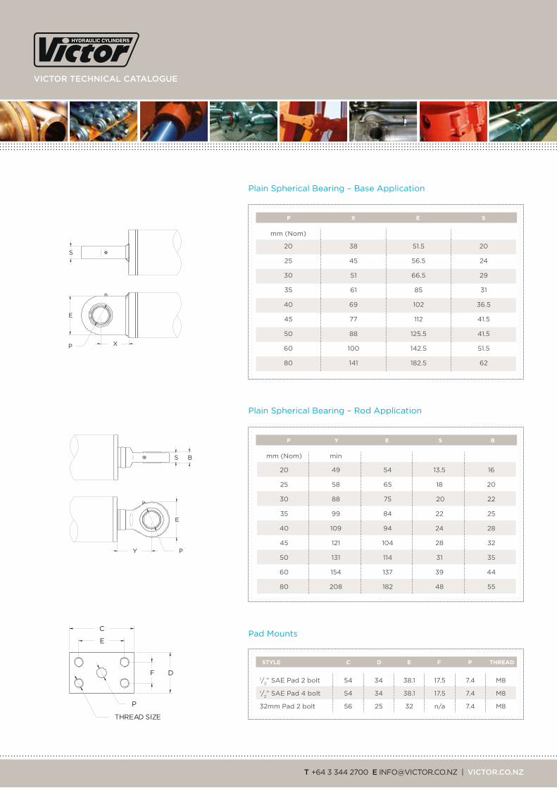
E
P X
S
C
E
DF
THREAD SIZE
P
E
P Y
S B
mm (nom)
20 38 51.5 20
25 45 56.5 24
30 51 66.5 29
35 61 85 31
40 69 102 36.5
45 77 112 41.5
50 88 125.5 41.5
60 100 142.5 51.5
80 141 182.5 62
mm (nom) min
20 49 54 13.5 16
25 58 65 18 20
30 88 75 20 22
35 99 84 22 25
40 109 94 24 28
45 121 104 28 32
50 131 114 31 35
60 154 137 39 44
80 208 182 48 55
1/2” SAE Pad 2 bolt 54 34 38.1 17.5 7.4 M8
1/2” SAE Pad 4 bolt 54 34 38.1 17.5 7.4 M8
32mm Pad 2 bolt 56 25 32 n/a 7.4 M8
P X E S
P Y E S B
STYLE C D E F P THREAD
Plain Spherical Bearing – Base Application
Plain Spherical Bearing – rod Application
Pad Mounts
Building on a 60-year tradition of innovation, quality and delivery
C P
D
A
F E
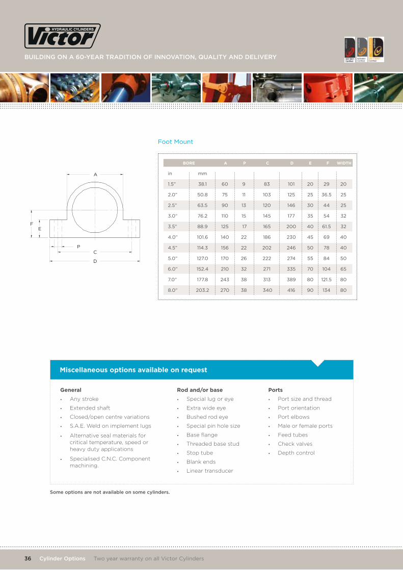
in mm
1.5” 38.1 60 9 83 101 20 29 20
2.0” 50.8 75 11 103 125 25 36.5 25
2.5” 63.5 90 13 120 146 30 44 25
3.0” 76.2 110 15 145 177 35 54 32
3.5” 88.9 125 17 165 200 40 61.5 32
4.0” 101.6 140 22 186 230 45 69 40
4.5” 114.3 156 22 202 246 50 78 40
5.0” 127.0 170 26 222 274 55 84 50
6.0” 152.4 210 32 271 335 70 104 65
7.0” 177.8 243 38 313 389 80 121.5 80
8.0” 203.2 270 38 340 416 90 134 80
BORE A P C D E F WIDTH
foot Mount
General
• Any stroke
• Extended shaft
• Closed/open centre variations
• S.A.E. Weld on implement lugs
• Alternative seal materials for critical temperature, speed or heavy duty applications
• Specialised C.N.C. Component machining.
Some options are not available on some cylinders.
Miscellaneous options available on request
Rod and/or base
• Special lug or eye
• Extra wide eye
• Bushed rod eye
• Special pin hole size
• Base flange
• Threaded base stud
• Stop tube
• Blank ends
• Linear transducer
Ports
• Port size and thread
• Port orientation
• Port elbows
• Male or female ports
• Feed tubes
• Check valves
• Depth control
36 Cylinder options two year warranty on all victor cylinders
viCtor teChniCal Catalogue
t +64 3 344 2700 e [email protected] | viCtor.Co.nZ
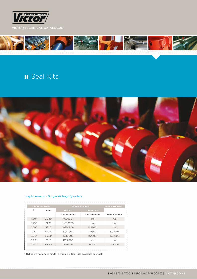
in mm GUIDED UNGUIDED
part number part number part number
1.00” 25.40 KGS0604 n/a n/a
1.25” 31.75 KGS0805 n/a n/a
1.50” 38.10 KGS0806 KUS06 n/a
1.75” 44.45 KGS1007 KUS07 KUW07
2.00” 50.80 KGS1008 KUS08 KUW08
2.25” 57.15 KGS1209 n/a n/a
2.50” 63.50 KGS1210 KUS10 KUW10
Displacement – Single Acting cylinders
CYLINDER BORE SCREWED HEAD WIRE RETAINED*
* Cylinders no longer made in this style. Seal kits available ex-stock.
Seal Kits

Building on a 60-year tradition of innovation, quality and delivery
in mm in mm part number part number
1.5” 38.1 0.7500” 19.05 KDS0603 KDW0603
1.5” 38.1 1.000” 25.40 KDS0604 KDW0604
2.0” 50.8 1.000” 25.40 KDS0804 KDW0804
2.0” 50.8 1.250” 31.75 KDS0805 KDW0805
2.0” 50.8 1.500” 38.10 KDS0806 n/a
2.5” 63.5 1.250” 31.75 KDS1005 KDW1005
2.5” 63.5 1.375” 34.92 KDS1055 n/a
2.5” 63.5 1.500” 38.10 KDS1006 KDW1006
2.5” 63.5 1.750” 44.45 KDS1007 n/a
2.5” 63.5 2.000” 50.80 KDS1008 n/a
3.0” 76.2 1.500” 38.10 KDS1206 KDW1206
3.0” 76.2 1.750” 44.45 KDS1207 KDW1207
3.0” 76.3 2.000” 50.80 KDS1208 n/a
3.0” 76.2 2.250” 57.15 KDS1209 n/a
3.0” 76.5 2.500” 63.50 KDS1210 n/a
3.0” 76.6 1.750” 44.45 KDS1407 KDW1407
3.0” 76.7 2.000” 50.80 KDS1408 KDW1408
3.0” 76.8 2.500” 63.50 KDS1410 n/a
ALL TYPES
4.0” 101.6 2.000” 50.80 KD1608
4.0” 101.6 2.500” 63.50 KD1610
4.0” 101.6 3.000” 76.20 KD1612
4.5” 114.3 2.250” 57.15 KD1809
4.5” 114.3 2.500” 63.50 KD1810
4.5” 114.3 3.000” 76.20 KD1812
5.0” 127.0 2.500” 63.50 KD2010
5.0” 127.0 3.000” 76.20 KD2012
5.0” 127.0 3.500” 88.90 KD2014
5.0” 127.0 4.000” 101.60 KD2016
6.0” 152.4 3.000” 76.20 KD2412
6.0” 152.4 4.000” 101.60 KD2416
7.0” 177.8 3.500” 88.90 KD2814
7.0” 177.8 4.000” 101.60 KD2816
8.0” 203.2 4.000” 101.60 KD3216
8.0” 203.2 5.000” 127.00 KD3220
CYLINDER BORE ROD DIAMETER SCREWED HEAD WIRE RETAINED*
Double Acting cylinders
Bearing rings are not included in seal kits.
order these parts separately if required.
* Cylinders no longer made in this style. Seal kits available ex-stock.
KdS Kit Double-acting Screwed
KdW Kit Double-acting Wire retained
Kd Kit Double-acting all types
KgS Kit Guided Screwed
KuS Kit Unguided Screwed
KuW Kit Unguided Wire retained
Key
38 Seal Kits two year warranty on all victor cylinders
viCtor teChniCal Catalogue
t +64 3 344 2700 e [email protected] | viCtor.Co.nZ
Design and Performance

Building on a 60-year tradition of innovation, quality and delivery
L2 L1
d2 d1
L2 L1
d2 d1
L1 x d1 = L2 x d2
L1 = L2 x d2 d1
FORMULA
F cosß x d1 = L cosø x d2
F =
or
L =
F sin(ß - ø) x d1 = L cosø (d1 + d2)
F =
or
L =
F sin(ß - ø) x d1 = L cosø (d1 + d2)
F =
or
L =
L cosø x d2 L cosø (d1 + d2) L cosø (d1 + d2)
F sin(ß - ø) x d1 F sin(ß - ø) x d1F cosß x d1
sin(ß - ø) x d1 sin(ß - ø) x d1
cosø (d1 + d2) cosø (d1 + d2) cosø x d2
FORMULA
F x d1 cosø = L x d2 cosøor
F cosø x d1 = L cosø x d2 where ø is less than 15˚, cos ø is
approximately equal to 1. L = F = F d1
d2 L d2 d1
FORMULA
FORMULA
F d1 = L d2
L = F = orF d1 L d2 d2 d1
FORMULA
FORMULA
d2
d1
L
F
d1
d2
F
Ø
Ø
L
or
L
F
d1
d2
ß
Ø
d1 d2
Ø
Ø
ß
F
L
ß
Ø
Ø
d1 d2
F
L
cosß x d1
Principles of moments
Simple lever Bent lever lever
lever variation Crane Crane and Beam
Moments = Force x Distance
but the direction of the force must be at right angles to the measurement of distance
therefore Moment = force x distance at right angles to force
or Moment = distance x component of force operating at right angles to distance.
LAW of MoMEntS: All moments in one direction equal all moments in the opposite direction
40 performance and design two year warranty on all victor cylinders

viCtor teChniCal Catalogue
t +64 3 344 2700 e [email protected] | viCtor.Co.nZ
Why shafts bend in hydraulic cylindersShafts in tension will not bend. Shafts in compression will bend if subjected to too much force. Excessive force may come from either too much pressure, or excessive mechanical loads applied to the shaft. For short shafts in compression, the limiting load is determined by the yield point of the material. For long shafts, the limiting load is a function of length and the mounting method.
calculate the shaft diameter neededThe method of supporting the ends of the shaft makes a considerable difference to the maximum load permitted. This difference is expressed by a constant called the “fixity factor” (ƒƒ). To calculate the maximum permitted extended length (E) for a given application and shaft diameter, multiply the “apparent length” (L) by the “fixity factor” (ƒƒ). Select the appropriate “fixity factor” (ƒƒ) from the application guide below. (L) can be obtained from Euler’s formula.
e = l x ƒƒ or l = e
ƒƒ
euler’S formula
For steel to En8 or AISI 1045, and a safety factor of 2.2 (i.e. a maximum permissible stress of 240 MPa), the formula is:
l = 2.108 d2 where l = “apparent” length of shaft (mm)
√p
d = diameter of shaft (mm)
p = 2.108 d2 2
l p = load (tonnes)
ALL tHESE oPtionS:
fixity factor chartfor rigidly mounted CylinderS: fixity factor for pin mounted CylinderS: fixity factor
E
E
E
E
E
E
E
E
E
E
E
E
E
E
E
E
E
E
rigidly fixed to piston rod with a long guide
Pivoted but well guided
rigidly fixed to piston rod with a short guide
Supported but not rigidly guided
not guided or supported
rigidly fixed to piston rod with a long guide
Pivoted but well guided
rigidly fixed to piston rod with a short guide
Supported but not rigidly guided
not guided or supported
rear clevis
rear trunnion
Mid trunnion
front trunnion
2.0
1.4
1.0
0.5
0.25
1.0
( )
Building on a 60-year tradition of innovation, quality and delivery
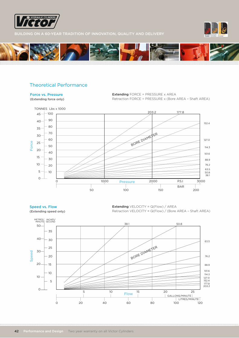
theoretical Performance
force vs. pressure (extending force only)
extending FORCE = PRESSURE x AREA
Retraction FORCE = PRESSURE x (Bore AREA – Shaft AREA)
5
10
15
20
25
30
35
40
45
0
TONNES Lbs x 1000
0 1000 2000 3000P.S.I
BAR
203.2 177.8
152.4
127.0
114.3
101.6
38.150.8
63.5
76.2
88.9
100
90
80
70
60
50
40
30
20
10
50 100 150 200
BORE DIAMETER
0
GALLONS/MINUTE
LITRES/MINUTE
5 10 15 20 25
20 40 60 80 100 120
METRES/MINUTE
INCHES/SECOND
10
20
30
40
50
0
38.1 50.8
63.5
76.2
88.9
101.6
203.2177.8152.4
114.3
127.0
5
10
15
20
25
30
35
BORE DIAMETER
5
10
15
20
25
30
35
40
45
0
TONNES Lbs x 1000
0 1000 2000 3000P.S.I
BAR
203.2 177.8
152.4
127.0
114.3
101.6
38.150.8
63.5
76.2
88.9
100
90
80
70
60
50
40
30
20
10
50 100 150 200
BORE DIAMETER
0
GALLONS/MINUTE
LITRES/MINUTE
5 10 15 20 25
20 40 60 80 100 120
METRES/MINUTE
INCHES/SECOND
10
20
30
40
50
0
38.1 50.8
63.5
76.2
88.9
101.6
203.2177.8152.4
114.3
127.0
5
10
15
20
25
30
35
BORE DIAMETER
extending VELOCITY = Q(Flow) / AREA
Retraction VELOCITY = Q(Flow) / (Bore AREA – Shaft AREA)Speed vs. flow (extending speed only)
fo
rce
Sp
ee
d
pressure
flow
42 performance and design two year warranty on all victor cylinders

viCtor teChniCal Catalogue
t +64 3 344 2700 e [email protected] | viCtor.Co.nZ
Cylinder Identification
to re-order cylinders and parts, please contact us with your unique code. if you do not know
your code, contact our sales team on +64 3 344 2700 who will be able to place your order for
you and provide your code number for easy re-ordering in the future.
• Hydraulic cylinders are usually described by stating the cylinder internal diameter (bore), shaft diameter and stroke. The type of cylinder (e.g. Compact S, SAE, etc) is also needed. Other useful information includes the closed and open centre dimensions, and details of the mounts and other hardware.
• All hydraulic cylinders made by Victor Hydraulics Limited are identified by a unique numeric code, stamped on the barrel of the cylinder. Typically, this is found in the vicinity of the head port.
• In some size ranges, the cylinder type identifies seal types, so please note if the cylinder is a screwed head design.

Building on a 60-year tradition of innovation, quality and delivery
12 KlondyKe drive, ChriStChurCh 8042
p.o. BoX 16235, ChriStChurCh 8441, neW Zealand
ph: +64 3 344 2700 | faX: +64 3 344 2701
email: [email protected]
VICTOR.CO.Nz