systems operation testing and adjusting · start the injection of fuel. also, the ecm de-energizes...
TRANSCRIPT

KENR6231July 2006
Systems OperationTesting and Adjusting2506-15 Industrial EngineM G A (Engine)MGB (Engine)M G D (Engine)

Important Safety InformationMost accidents that involve product operation, maintenance and repair are caused by failure toobserve basic safety rules or precautions. An accident can often be avoided by recognizing potentiallyhazardous situations before an accident occurs. A person must be alert to potential hazards. Thisperson should also have the necessary training, skills and tools to perform these functions properly.
Improper operation, lubrication, maintenance or repair of this product can be dangerous andcould result in injury or death.
Do not operate or perform any lubrication, maintenance or repair on this product, until you haveread and understood the operation, lubrication, maintenance and repair information.
Safety precautions and warnings are provided in this manual and on the product. If these hazardwarnings are not heeded, bodily injury or death could occur to you or to other persons.
The hazards are identified by the “Safety Alert Symbol” and followed by a “Signal Word” such as“DANGER”, “WARNING” or “CAUTION”. The Safety Alert “WARNING” label is shown below.
The meaning of this safety alert symbol is as follows:
Attention! Become Alert! Your Safety is Involved.
The message that appears under the warning explains the hazard and can be either written orpictorially presented.
Operations that may cause product damage are identified by “NOTICE” labels on the product and inthis publication.
Perkins cannot anticipate every possible circumstance that might involve a potential hazard. Thewarnings in this publication and on the product are, therefore, not all inclusive. If a tool, procedure,work method or operating technique that is not specifically recommended by Perkins is used,you must satisfy yourself that it is safe for you and for others. You should also ensure that theproduct will not be damaged or be made unsafe by the operation, lubrication, maintenance orrepair procedures that you choose.
The information, specifications, and illustrations in this publication are on the basis of information thatwas available at the time that the publication was written. The specifications, torques, pressures,measurements, adjustments, illustrations, and other items can change at any time. These changes canaffect the service that is given to the product. Obtain the complete and most current information beforeyou start any job. Perkins dealers or Perkins distributors have the most current information available.
When replacement parts are required for thisproduct Perkins recommends using Perkins replacement parts.Failure to heed this warning can lead to prema-ture failures, product damage, personal injury ordeath.

KENR6231 3Table of Contents
Table of Contents
Systems Operation Section
General Information ................................................ 4Electronic Control System Components ................. 6Fuel System ........................................................... 8Air Inlet and Exhaust System ............................... 12Lubrication System .............................................. 14Cooling System .................................................... 16Basic Engine ......................................................... 17Electrical System ................................................. 18
Testing and Adjusting Section
Testing and AdjustingBelt Tension Chart ................................................ 22
Fuel SystemFuel System - Inspect ........................................... 23Air in Fuel - Test .................................................... 23Electronic Unit Injector - Adjust ............................. 24Electronic Unit Injector - Test ................................ 24Finding Top Center Position for No. 1 Piston ........ 25Fuel Quality - Test ................................................. 26Fuel System - Prime ............................................. 26Fuel System Pressure - Test ................................. 27Gear Group (Front) - Time .................................... 28
Air Inlet and Exhaust SystemAir Inlet and Exhaust System - Inspect ................. 31Turbocharger - Inspect .......................................... 32Exhaust Temperature - Test .................................. 34Engine Crankcase Pressure (Blowby) - Test ........ 35Engine Valve Lash - Inspect/Adjust ...................... 35
Lubrication SystemEngine Oil Pressure - Test .................................... 37Excessive Bearing Wear - Inspect ........................ 39Excessive Engine Oil Consumption - Inspect ....... 39Increased Engine Oil Temperature - Inspect ........ 40
Cooling SystemCooling System - Check (Overheating) ................ 41Cooling System - Inspect ...................................... 42Cooling System - Test ........................................... 43Water Temperature Regulator - Test ..................... 45Water Pump - Test ................................................ 46
Basic EnginePiston Ring Groove - Inspect ................................ 47Connecting Rod Bearings - Inspect ...................... 47Main Bearings - Inspect ........................................ 47Cylinder Block - Inspect ........................................ 47Cylinder Liner Projection - Inspect ........................ 48Flywheel - Inspect ................................................. 50Flywheel Housing - Inspect ................................... 51Vibration Damper - Check .................................... 53
Electrical SystemBattery - Test ......................................................... 54
Charging System - Test ........................................ 54Electric Starting System - Test .............................. 55
Index Section
Index ..................................................................... 56

4 KENR6231Systems Operation Section
Systems Operation Sectioni02550114
General Information
The following model views show the 2506 Enginefeatures. Due to individual applications, your enginemay appear different from the illustrations.
g01288248Illustration 1Typical exampleLeft side view
(1) Front timing gear housing(2) Fuel priming pump(3) Electronic Control Module (ECM)
(4) Flywheel housing(5) Fuel filters(6) Fuel transfer pump
(7) Vibration Damper

KENR6231 5Systems Operation Section
g01288247Illustration 2Typical exampleRight side view
(8) Exhaust manifold(9) Turbocharger
(10) Temperature regulator housing(11) Water pump
(12) Oil cooler(13) Oil filter
Starting the EngineThe Electronic Control Module (ECM) willautomatically provide the correct amount of fuel thatis necessary to start the engine. If the engine failsto start in 30 seconds, the starter switch should bereleased. The starting motor should be allowed tocool for 30 seconds before being used again.
Cold Mode OperationThe ECM will set the cold start strategy when thecoolant temperature is below 18 °C (64 °F).
Cold mode operation will be deactivated when any ofthe following conditions have been met:
• Coolant temperature reaches 18 °C (64 °F).
• The engine has been running for fourteen minutes.
Cold mode operation varies the fuel injection amountfor white smoke cleanup. Cold mode operation alsovaries the timing for white smoke cleanup. Theengine operating temperature is usually reachedbefore the walk-around inspection is completed.

6 KENR6231Systems Operation Section
i02589727
Electronic Control SystemComponents
g01279775Illustration 3(1) Coolant temperature sensor(2) Camshaft position sensor(3) Inlet manifold pressure sensor
(4) Fuel temperature sensor(5) Inlet manifold temperature sensor(6) Electronic control module (ECM)
(7) Engine oil pressure sensor(8) Atmospheric pressure sensor(9) Crankshaft position sensor
The electronic control system is integrally designedinto the engine’s fuel system and the engine’s airinlet and exhaust system in order to electronicallycontrol the fuel delivery and the injection timing. Theelectronic control system provides increased timingcontrol and fuel air ratio control in comparison toconventional mechanical engines. Injection timingis achieved by precise control of injector firing time,and engine rpm is controlled by adjusting the firingduration. The Electronic Control Module (ECM)energizes the solenoid in the unit injector in order tostart the injection of fuel. Also, the ECM de-energizesthe unit injector solenoids in order to stop injectionof fuel. Refer to Systems Operation, Testing andAdjusting, “Fuel System” for a complete explanationof the fuel injection process.
The engine uses the following types of electroniccomponents:
• Inputs
• Controls
• Outputs
An input component is one that sends an electricalsignal to the ECM. The signal that is sent varies inone of the following ways:
• Voltage
• Frequency
• Pulse width
The variation of the signal is in response to a changein some specific system of the vehicle. The ECMsees the input sensor signal as information about thecondition, environment, or operation of the vehicle.

KENR6231 7Systems Operation Section
A control component (ECM) receives the inputsignals. Electronic circuits inside the controlcomponent evaluate the signals from the inputcomponents. These electronic circuits also supplyelectrical energy to the output components of thesystem. The electrical energy that is supplied tothe output components is based on predeterminedcombinations of input signal values.
An output component is one that is operated by acontrol module. The output component receiveselectrical energy from the control component. Theoutput component uses that electrical energy in oneof two ways. The output component can use thatelectrical energy in order to perform work. The outputcomponent can use that electrical energy in order toprovide information.

8 KENR6231Systems Operation Section
i02550058
Fuel System
g01282152Illustration 4
Fuel system schematic(1) Fuel return line(2) Electronic unit injectors(3) Fuel gallery(4) Fuel priming pump(5) Fuel cooler
(6) Fuel tank(7) Secondary fuel filter(8) Primary fuel filter(9) Fuel transfer pump(10) Fuel temperature sensor
The fuel supply circuit is a conventional design forengines with electronic unit injection. A fuel tank (6)is used to store the fuel prior to use by the engine. Aprimary fuel filter/water separator (8) is placed intothe fuel supply circuit in order to remove large debrisfrom the fuel. This debris may have entered thefuel tank during fueling. The debris may have alsoentered the fuel tank through the vent for the fueltank. The primary filter element also separates waterfrom the fuel. The water is collected in the bowl at thebottom of the primary fuel filter/water separator.
Note: The inlet fuel temperature to the fuel transferpump must not exceed 79 °C (175 °F) when theengine has reached normal operating temperature.Fuel temperatures above 79 °C (175 °F) will reducethe life of the fuel transfer pump check valves. Thefuel efficiency and the engine power output arereduced when the fuel temperature increases from30 °C (86 °F) to 70 °C (158 °F).

KENR6231 9Systems Operation Section
Fuel from the tank (6) flows to the fuel filter base.The fuel filter base contains the primary fuel filterand the secondary fuel filter. The fuel flows throughcored passages in the fuel filter base. The fuelpriming pump (4) is mounted on the fuel filter base.The fuel priming pump is used in order to manuallypump the fuel into the fuel system after the system,or parts of the system have been drained. The fuelpriming pump is used in order to refill the fuel systemafter air has been introduced into the system. Formore information on priming the fuel system, referto Systems Operation, Testing and Adjusting, “FuelSystem - Prime”.
As the fuel flows through cored passages in the fuelfilter base, the fuel is directed into the primary fuelfilter (8). Fuel flows out of the fuel filter and returnsto the passages in the fuel filter base. Prior to exitingthe fuel filter base, the fuel temperature is sampledby the fuel temperature sensor (10). The signalsthat are generated by the sensors are used by theengine control in order to monitor the condition of theengine’s components.
The fuel flows from the fuel filter base to the fueltransfer pump (9). The fuel transfer pump (9) is a geartype pump with fixed clearances. The fuel transferpump (9) incorporates an internal relief valve thatprotects the fuel system from extreme pressure. Inthe case of extreme pressure, fuel is redirected backto the inlet of the fuel transfer pump (9). An outletcheck valve is used in order to prevent pressurizedfuel leakage back through the pump. The fuel transferpump (9) is located in the front of the engine. The fueltransfer pump (9) is driven by the front gear train.
The fuel flows from the fuel transfer pump (9) to thesecondary fuel filter (7). The fuel is filtered in orderto remove small abrasive particles that will causepremature wear to fuel system components. The fuelflows from the secondary fuel filter (7) to the fuel filterbase.
The fuel is then directed from the fuel filter basethrough the fuel return line (1) to fuel manifold (3) thatruns the length of the cylinder head. A continuousflow of fuel is supplied to the electronic unit injectors(2) in order to perform the following tasks:
• Supply fuel for injection
• Remove excessive heat from the injectors.
• Remove air that may accumulate in the fuelsystem.
The fuel exits the fuel gallery and returns to the fuelfilter base. A pressure regulating valve is located inthe fuel filter base. The pressure regulating valveregulates the pressure for the fuel system. A sufficientamount of back pressure is maintained in the systemin order to ensure a continuous availability of fuel tothe electronic unit injectors. The fuel flows from thefuel filter base to the fuel cooler (5). The fuel flowsfrom the fuel cooler (5) back to the tank (6).
Fuel System Electronic ControlCircuit
g00451841Illustration 5Electronic governor(1) Signals to the electronic unit injectors(2) Fuel injection control(3) Fuel position(4) Electronic governor(5) Desired rpm(6) Coolant temperature(7) TC for No. 1 cylinder(8) FRC fuel position(9) Rated fuel position(10) FCR maps(11) Torque maps(12) Engine speed/timing sensor(13) Engine speed/timing signals’ interpreter(14) Engine rpm(15) Coolant temperature sensor(16) Boost pressure sensor(17) Boost pressure
The injection pump, the fuel lines, and the nozzlesthat are used in the traditional Perkins diesel engineshave been replaced with an electronically controlled,mechanically actuated electronic unit injector in eachcylinder. A solenoid on each injector controls theamount of fuel that is delivered by the injector. AnElectronic Control Module (ECM) sends a signal toeach injector solenoid in order to provide completecontrol of the engine.

10 KENR6231Systems Operation Section
Fuel Injection
The ECM controls the amount of fuel that is injectedby varying the signals that are sent to the injectors.The ECM sends a high voltage signal to the solenoidin order to energize the solenoid. The injectorswill inject fuel only while the injector solenoid isenergized. By controlling the timing and the durationof the voltage signal, the ECM can control injectiontiming and the amount of fuel that is injected.
The ECM sets certain limits on the amount of fuel thatcan be injected. “FRC” is a limit which controls theamount of air and of fuel for the purpose of emissioncontrol. This limit is based on the boost pressure.When the ECM senses a higher boost pressure, theECM increases the “FRC” limit. “Rated Fuel Pos” isa limit that is based on the horsepower rating of theengine. This is similar to the rack stops and to thetorque spring on a mechanically governed engine.“Rated Fuel Pos” provides horsepower and torquecurves for a specific engine family and for a specificengine rating. All of these limits are programmed intothe personality module by the factory. These limitsare not programmable by the service technician.
Injection timing depends on three factors: the enginespeed (rpm), the engine load, and the operationalconditions of the engine. The ECM determines thetop center position of No. 1 cylinder from the signalthat is provided by the engine speed/timing sensor.The ECM decides when the injection should occurrelative to the top center position. The ECM thenprovides the signal to the electronic unit injector atthe desired time.
Electronic Unit Injector Mechanism
g00291269Illustration 6
Electronic unit injector mechanism(1) Electronic unit injector(2) Adjusting nut(3) Rocker arm assembly(4) Camshaft lobe
The electronic unit injector mechanism providesthe downward force that is required to pressurizethe fuel in the electronic unit injector pump. Theelectronic unit injector (1) allows fuel to be injectedinto the combustion chamber with precise timing.Movement is transmitted from the camshaft lobe (4)for the electronic unit injector through the rocker armassembly (3) to the top of the electronic unit injector.The adjusting nut (2) allows the injector lash to beadjusted. For the proper setting of the injector lash,refer to the topic on adjustment of the electronic unitinjector in Systems Operation, Testing and Adjusting,“Electronic Unit Injector - Adjust”.

KENR6231 11Systems Operation Section
Electronic Unit Injector
g00984466Illustration 7Electronic unit injector(1) Spring(2) Solenoid connection to the Electronic Control Module (ECM)(3) Solenoid valve assembly(4) Plunger assembly(5) Barrel(6) Seal(7) Seal(8) Spring(9) Spacer(10) Body(11) Check valve
Fuel at low pressure from the fuel supply manifoldenters the electronic unit injector at the fill portthrough drilled passages in the cylinder head.
As the electronic unit injector mechanism transfersthe force to the top of the electronic unit injector,spring (1) is compressed and plunger (4) is drivendownward. This action displaces fuel through thevalve in solenoid valve assembly (3), and into thereturn manifold to the fuel tank. As the plunger travelsdownward, the passage in barrel (5) is closed by theoutside diameter of the plunger. The passages withinbody (10) and along check valve (11) to the injectortip already contain fuel for injection. After the passagein the plunger barrel is closed, the injector is ready forinjection at any time. The start of injection relies onthe software in the Electronic Control Module (ECM).
When the solenoid valve assembly is energizedfrom a signal across solenoid connection (2), thevalve closes and fuel pressure is elevated in theinjector tip. Injection begins at 34500 ± 1900 kPa(5000 ± 275 psi) as the force of spring (8) abovespacer (9) is overcome. The check valve beginsto lift from the valve seat. The pressure continuesto rise as the plunger cycles through a full stroke.After the correct amount of fuel has been dischargedinto the cylinder, the ECM removes the signal to thesolenoid connection. The solenoid valve assemblyis de-energized and the valve in the solenoid valveassembly is opened. The high pressure fuel is thendumped through the spill port and into the fuel returnmanifold. The fuel is then returned to the fuel tank.The check valve in the injector tip seats as thepressure in the tip decreases.
The duration of injection meters the fuel that isconsumed during the fuel injection process. Injectionduration is controlled by the governor logic that isprogrammed into the ECM.
As the camshaft lobe rotates past the point ofmaximum lobe lift, the force on top of the electronicunit injector is removed and the spring for the injectormechanism is allowed to expand. The plunger returnsto the original position. This uncovers the fuel supplypassage into the plunger barrel in order to refill theinjector pump body. The fuel at low pressure is againallowed to circulate through the fuel injector body.After circulating through the fuel injector body, thefuel flows out of the spill port. This continues until thesolenoid valve assembly is re-energized for anotherinjection cycle.

12 KENR6231Systems Operation Section
i02550062
Air Inlet and Exhaust System
g01046036Illustration 8
Air inlet and exhaust system schematic(1) Inlet to the engine(2) Aftercooler core(3) Inlet air line(4) Exhaust outlet from turbocharger(5) Turbine side of turbocharger(6) Compressor side of turbocharger(7) Air cleaner
The engine components of the air inlet and exhaustsystem control the quality of air and the amount ofair that is available for combustion. The componentsof the air inlet and exhaust system are the followingcomponents:
• Air cleaner
• Turbocharger
• Aftercooler
• Cylinder head
• Valves and valve system components
• Piston and cylinder
• Exhaust manifold
The turbocharger compressor wheel pulls inlet airthrough the air cleaner and into the air inlet. The airis compressed and this causes the air to become hot.The air flows through aftercooler core (2) and thetemperature of the compressed air lowers. This helpsto provide increased horsepower output. Aftercoolercore (2) is a separate cooler core that is mounted infront of the engine radiator. The engine fan causesambient air to move across both cores. This cools theturbocharged inlet air and the engine coolant.
Air is forced from the aftercooler into inlet manifold(1). The air flow from the inlet port into the cylindersis controlled by inlet valves.
g00615497Illustration 9Air inlet and exhaust system(2) Aftercooler core(4) Exhaust outlet(5) Turbine side of turbocharger(6) Compressor side of turbocharger(8) Exhaust manifold(9) Exhaust valve(10) Inlet valve(11) Air inlet
Each cylinder has two inlet valves (10) and twoexhaust valves (9) in the cylinder head. The inletvalves open on the inlet stroke. When the inlet valvesopen, compressed air from the inlet port within theinlet manifold is pushed into the cylinder. The inletvalves close when the piston begins the compressionstroke. The air in the cylinder is compressed and thefuel is injected into the cylinder when the piston isnear the top of the compression stroke. Combustionbegins when the fuel mixes with the air. The force ofcombustion pushes the piston on the power stroke.The exhaust valves open and the exhaust gasesare pushed through the exhaust port into exhaustmanifold (8). After the piston finishes the exhauststroke, the exhaust valves close and the cycle beginsagain.
Exhaust gases from the exhaust manifold flowinto the turbine side of turbocharger (5). The hightemperature exhaust gases cause the turbochargerturbine wheel to turn. The turbine wheel is connectedto the shaft that drives the compressor wheel.Exhaust gases from the turbocharger pass throughexhaust outlet (4), through a muffler, and through anexhaust stack.

KENR6231 13Systems Operation Section
Turbocharger
g00291085Illustration 10
Turbocharger(4) Air inlet(5) Compressor housing(6) Compressor wheel(7) Bearing(8) Oil inlet port(9) Bearing(10) Turbine housing(11) Turbine wheel(12) Exhaust outlet(13) Oil outlet port(14) Exhaust inlet
Turbocharger (3) is mounted to exhaust manifold (2)of the engine. All of the exhaust gases go from theexhaust manifold through the turbocharger.
The exhaust gases enter the turbocharger and theturbine wheel is turned. Because the turbochargerturbine wheel is connected by a shaft to theturbocharger compressor wheel, the turbine wheeland the compressor wheel turn at very high speeds.The rotation of the compressor wheel pulls cleanair through the compressor housing air inlet. Theaction of the compressor wheel blades causes acompression of the inlet air. This compression allowsa larger amount of air to enter the engine. With moreair in the engine, the engine is able to burn more fuel.The overall effect is an increase in power.
Bearing (7) and bearing (9) in the turbocharger useengine oil that is under pressure for lubrication. Thelubrication for the bearings flows through oil inlet port(8) and into the inlet port in the center section of theturbocharger cartridge. The oil exits the turbochargerthrough oil outlet port (13). The oil then returns tothe engine oil pan through the oil drain line for theturbocharger.
Valves And Valve Mechanism
g01046041Illustration 11Valve system components
(1) Valve bridge(2) Rocker arm(3) Camshaft(4) Rotocoil(5) Valve spring(6) Valve guide(7) Valve
The valves and the valve mechanism control the flowof inlet air into the cylinders during engine operation.The valves and the valve mechanism control the flowof exhaust gases out of the cylinders during engineoperation.

14 KENR6231Systems Operation Section
g01033757Illustration 12
Components of the gear train(8) Timing mark(9) Camshaft gear(10) Adjustable idler gear(11) Idler gear(12) Timing mark(13) Cluster gear(14) Crankshaft gear(15) Oil pump gear
The inlet valves and the exhaust valves are openedby the valve mechanism. The inlet valves andthe exhaust valves are also closed by the valvemechanism. This occurs as the rotation of thecrankshaft causes camshaft (3) to rotate. Camshaftgear (9) is driven by a series of two idler gears (10)and (11). Idler gear (11) is driven by cluster gear (13).Cluster gear (13) is driven by crankshaft gear (14).Timing mark (12) and timing mark (8) are aligned inorder to provide the correct relationship between thepiston and the valve movement.
The camshaft has three lobes for each cylinder.One lobe operates the inlet valves. A second lobeoperates the exhaust valves. The third lobe operatesthe unit injector mechanism. The camshaft lobes turnand the rocker arms move. Movement of the rockerarms will make the inlet and exhaust valve bridgesmove. These bridges allow one rocker arm to actuatetwo valves at the same time. Each cylinder has twoinlet valves and two exhaust valves. Each valve hasone valve spring (5). The spring closes the valve.
Rotocoils (4) cause the valves to rotate while theengine is running. Valve rotation provides a longerservice life. Valve rotation also minimizes carbondeposits on the valves.
Adjustable idler gear (10) is designed to provide therequired gear backlash between nonadjustable idlergear (11) and camshaft gear (9). If the cylinder head isremoved, tolerances of the components will change.The components that change are the cylinder headand the head gasket. The adjustable idler gear mustbe relocated. For information on setting the correctbacklash, refer to Systems Operation, Testing andAdjusting, “Gear Group (Front) - Time”.
The camshaft drive gear has integral pendulumswhich act as a vibration damper for the front geargroup. These pendulums are designed to counteractthe torsional forces from the injector pulses. Thiseliminates vibration and noise. The engine also runssmoother at all operating speeds.
i02550074
Lubrication System
Lubrication System ComponentsThe lubrication system has the following components:
• Oil pan
• Oil pump
• Oil cooler
• Oil filter
• Turbocharger oil lines
• Oil passages for the cylinder block

KENR6231 15Systems Operation Section
Oil Flow Through The Oil Filter And OilCooler
g00562123Illustration 13
Oil flow when the engine is warm.(1) Oil manifold(2) Oil supply line(3) Oil return line(4) Oil filter(5) Bypass valve for the oil filter(6) Oil pan(7) Oil pump(8) Bypass valve for the oil cooler(9) Suction lines(10) Oil cooler(11) Bypass valve for the oil pump
When the engine is warm, oil is drawn from the oilpan (6) through the suction lines (9) to the oil pump(7). The oil pump pushes the hot oil through the oilcooler (10). The oil is then sent to the oil filter (4).Oil from the oil filter is sent to the oil manifold (1) inthe cylinder block and to the oil supply line (2) for theturbocharger. Oil from the turbocharger goes backthrough the oil return line (3) to the oil pan.
g00562383Illustration 14Oil flow when the engine Is cold.
(1) Oil manifold(2) Oil supply line(3) Oil return line(4) Oil filter(5) Bypass valve for the oil filter(6) Oil pan(7) Oil pump(8) Bypass valve for the oil cooler(9) Suction lines(10) Oil cooler(11) Bypass valve for the oil pump
When the engine is cold, oil is drawn from the oilpan (6) through the suction lines (9) to the oil pump(7). When the oil is cold, an oil pressure differentialin the bypass valves causes the bypass valves toopen. These bypass valves then provide immediatelubrication to all of the engine components when coldoil with high viscosity causes a restriction to oil flowthrough the oil cooler (10) and the oil filter (4). The oilpump then pushes the cold oil through the bypassvalve (8) for the oil cooler and through the bypassvalve (5) for the oil filter. The oil then goes to the oilmanifold (1) in the cylinder block and to the supplyline (2) for the turbocharger. Oil from the turbochargergoes back through the oil return line (3) to the oil pan.
When the oil is warm, an oil pressure differential inthe bypass valves also causes the bypass valves toclose. There is normal oil flow through the oil coolerand the oil filter.
The bypass valves will also open when there isa restriction in the oil cooler or the oil filter. Thisprevents a restricted oil filter or a restricted oil coolerfrom stopping the lubrication of the engine. Thesystem pressure is limited by the oil pump bypassvalve (11).

16 KENR6231Systems Operation Section
Oil Flow In The Engine
g00431790Illustration 15
Engine oil flow schematic
(1) Rocker arm shaft(2) Oil passage to air compressor(3) Camshaft bearing journals(4) Oil passage to adjustable idler gear
(5) Oil passage to the fixed idler stub shaft(6) Oil passage to cluster idler gear(7) Oil manifold(8) Piston cooling jet
(9) Crankshaft main bearings(10) Oil passage from filter
The oil from the oil manifold (7) is sent underpressure through drilled passages to the crankshaftmain bearings (9). The oil flows through drilled holesin the crankshaft. This oil lubricates the connectingrod bearings. A small amount of oil is sent to thepiston cooling jets (8). The piston cooling jets sprayoil on the underside of the pistons.
Oil flows through passages in the timing gear housingand the accessory drive gear. This oil flows to the aircompressor through the oil passage (2).
Oil passage (4) provides oil to the adjustable idlergear. Oil passage (5) provides oil to the fixed idlergear. Oil passage (6) provides oil to the cluster gear.The oil flows through a passage in the shafts of thegears.
There is a pressure control valve in the oil pump.This valve controls the pressure of the oil that flowsfrom the oil pump.
Oil passage (9) provides lubrication to the rearcrankshaft seal. This ensures a long service life forthe rear crankshaft seal.
Oil flows into the cylinder head via a hollow locatingdowel in the top deck of the cylinder block. Oil travelsto the camshaft bearing journals (3) and the threecenter rocker arm shaft supports through drilledpassages in the cylinder head. The supports supplyoil to each rocker shaft. Oil flows to the bushings ofthe fuel injector rocker arm through holes in the rockerarm shaft (1). This same oil lubricates the valve andthe rollers. Oil flows through drilled passages in therocker arms. This oil lubricates the roller, the valvebridge and the contact surfaces of the actuator of theunit injector. Splash oil lubrication is used to lubricateother components of the valve system.
Excess oil returns to the engine oil pan.
i02550118
Cooling System
This engine has a pressure type cooling system thatis equipped with a shunt line.

KENR6231 17Systems Operation Section
A pressure type cooling system gives twoadvantages. First, the cooling system can beoperated safely at a temperature that is higher thanthe boiling point of water. Next, cavitation in the waterpump is prevented. It is more difficult for air or steampockets to be made in the cooling system.
Note: Use Perkins ELC in an Air-To-Air Aftercoolersystem. Refer to Operation and Maintenance Manual,“Fluid Recommendations” for more information. Thiskeeps the temperature range of the coolant highenough for efficient performance.
g01096647Illustration 16Cooling system for a warm engine
(1) Cylinder head(2) Water temperature regulator(3) Outlet pipe(4) Vent line(5) Vent tube(6) Shunt line(7) Pipe(8) Water pump(9) Cylinder block(10) Oil cooler(11) Inlet pipe(12) Radiator
In operation, the water pump (8) sends most of thecoolant from the radiator (12) to the oil cooler (10).
The coolant from the oil cooler (10) goes into thecylinder block (9) through a bonnet and an elbow.The coolant goes around the cylinder liners, throughthe water directors and into the cylinder head.
The water directors send the flow of coolant aroundthe valves and the passages for exhaust gases in thecylinder head. The coolant then goes to the front ofthe cylinder head. At this point, water temperatureregulator (2) controls the direction of coolant flow.
The water temperature regulator (2) is closed whenthe engine is cold. The coolant flows through theregulator housing and pipe (7) back to water pump(8).
If the coolant is at normal operating temperature,the water temperature regulator (2) opens and thecoolant flows to the radiator (12) through the outletpipe (3). The coolant becomes cooler as the coolantmoves through the radiator. When the coolant gets tothe bottom of the radiator, the coolant goes throughthe inlet pipe (11) and into the water pump (8).
Note: The water temperature regulator (2) is animportant part of the cooling system. The watertemperature regulator (2) divides the coolant flowbetween the radiator (12) and the bypass pipe (7).This will maintain the correct temperature. If thewater temperature regulator is not installed in thesystem, there is no mechanical control. Most of thecoolant will go through the bypass. This will causethe engine to overheat in hot weather. If a highervolume of coolant goes through the radiator, theengine will not reach normal operating temperatures.This occurs during cold weather.
Shunt line (6) gives several advantages to the coolingsystem. The shunt line gives a positive coolantpressure at the water pump inlet that prevents pumpcavitation. A small flow of coolant constantly goesthrough shunt line (6) to the inlet of water pump(8). This causes a small amount of coolant to moveconstantly through the vent tube (5). The flow throughthe vent tube is small and the volume of the uppercompartment is large. Air in the coolant is removedas the coolant goes into the upper compartment.
The vent line is used to fill the cooling system withcoolant for the first time. This will purge any air out ofthe top of a bottom filled system.
i02550119
Basic Engine
Cylinder Block AssemblyPassages supply the lubrication for the crankshaftbearings and the piston crowns. These passagesare cast into the cylinder block. Oil is supplied to thepassages by the cylinder block’s oil manifold.
The cylinder liner is an induction hardened liner. Asteel spacer plate provides improved reusability anddurability.

18 KENR6231Systems Operation Section
Cylinder Head AssemblyThe cylinder head is a one-piece cast iron head. Thecylinder head supports the camshaft. Steel reinforcedbearings are pressed into each bore. The bearingsare lubricated under pressure. Bridge dowels havebeen eliminated as the valve train uses floating valvebridges.
Thermal efficiency is enhanced by the use ofstainless steel thermal sleeves in each exhaust port.The sleeves reduce the amount of heat rejection tothe cooling system. The sleeves then transfer thethermal energy to the turbocharger.
The unit injector is mounted in a stainless steeladapter. This adapter has been pressed into thecylinder head injector bore.
Pistons, Rings And ConnectingRodsThe piston is a one-piece steel design that is retainedby the piston pin to the small end of the connectingrod. The pistons have three rings that are locatedin grooves in the steel crown. These rings seal thecombustion gas. The rings provide control of the oil.The top ring has a barrel face. The second ring hasa tapered face and the ring has a coating of chromefinish for the face. The third ring is the oil ring. Thethird ring has a coil spring expander.
The connecting rod is a conventional design. Thecap of the connecting rod is attached to the shank bytwo bolts that are threaded into the shank. Each sideof the small end of the connecting rod is machinedat an angle of 12 degrees in order to fit within thepiston cavity.
CrankshaftThe crankshaft converts the combustion force in thecylinder into rotating torque. A vibration damper isused at the front of the crankshaft in order to reducethe torsional vibrations.
The crankshaft drives a group of gears (front geartrain) on the front of the engine. The front geartrain provides power for the following components:camshaft, water pump, oil pump, fuel transferpump, and accessory items that are specific to theapplication.
The cylinder block has seven main bearings thatsupport the crankshaft. The cylinder block uses twobolts to hold each of the bearing caps to the block.
The crankcase uses a lip seal at both ends of thecrankshaft.
CamshaftThe camshaft has three lobes at each cylinder.These lobes allow the camshaft to operate the unitinjector, the exhaust valves, and the inlet valves. Thecamshaft is supported in the cylinder head by sevenjournals which are fit with bearings. The camshaftgear contains integral roller dampers that counteractthe torsional vibrations that are generated by thehigh fuel pressure during fuel injector operation. Thedesign reduces gear train noise. The camshaft isdriven by an adjustable idler gear which is turned bya fixed idler gear which is turned by a cluster idlergear in the front gear train. Each bearing journal islubricated from the oil manifold in the cylinder head.A thrust plate that is located at the front controls theend play of the camshaft. Timing of the camshaft isaccomplished by aligning marks on the crankshaftgear and idler gear, and camshaft gear with a markon the front timing plate.
i02554889
Electrical System
Grounding PracticesProper grounding for the machine electrical systemand engine electrical systems is necessary forproper machine performance and reliability. Impropergrounding will result in uncontrolled electrical circuitpaths and unreliable electrical circuit paths.
Uncontrolled engine electrical circuit paths can resultin damage to main bearings, crankshaft bearingjournal surfaces, and aluminum components.
To ensure proper functioning of the vehicle andengine electrical systems, an engine-to-frame groundstrap with a direct path to the negative battery postmust be used. This may be provided by way of astarting motor ground, a frame to starting motorground, or a direct frame to engine ground.
An engine-to-frame ground strap must be used inorder to connect the grounding stud of the engine tothe frame of the vehicle and to the negative batterypost.

KENR6231 19Systems Operation Section
g01028488Illustration 17
Typical exampleGrounding Stud To Battery Ground (“-”)
g01028479Illustration 18Typical example
Alternate Grounding Stud To Battery Ground (“-”)
The engine must have a wire ground to the battery.
Ground wires or ground straps should be combinedat ground studs that are only for ground use. All ofthe grounds should be tight and free of corrosion.
All of the ground paths must be capable of carryingany likely current faults. An AWG #0 or larger wire isrecommended for the grounding strap to the cylinderhead.
The engine alternator should be battery groundwith a wire size that is capable of managing the fullcharging current of the alternator.
NOTICEWhen boost starting an engine, the instructions in Op-eration and Maintenance Manual, “Engine Starting”should be followed in order to properly start the en-gine.
This engine is equipped with a 24 volt starting system.Only equal voltage for boost starting should be used.The use of a higher voltage will damage the electricalsystem.
The Electronic Control Module (ECM) must be dis-connected at the “J1/P1” and “J2/P2” locations beforewelding on the vehicle.
The engine has several input components which areelectronic. These components require an operatingvoltage.
Unlike many electronic systems of the past, thisengine is tolerant to common external sources ofelectrical noise. Buzzers that use electrical energycan cause disruptions in the power supply. If buzzersare used anywhere on the machine, the engineelectronics should be powered directly from thebattery system through a dedicated relay. The engineelectronics should not be powered through a commonpower bus with other keyswitch activated devices.
Engine Electrical SystemThe electrical system has the following separatecircuits:
• Charging
• Starting (If equipped)
• Accessories with low amperage
The charging circuit is in operation when the engineis running. An alternator makes electricity for thecharging circuit. A voltage regulator in the circuitcontrols the electrical output in order to keep thebattery at full charge.
The starting circuit is activated only when the startswitch is activated.
Charging System Components
Alternator
The alternator is driven by a belt from the crankshaftpulley. This alternator is a three-phase, self-rectifyingcharging unit, and the regulator is part of thealternator.

20 KENR6231Systems Operation Section
The alternator design has no need for slip ringsand the only part that has movement is the rotorassembly. All conductors that carry current arestationary. The following conductors are in the circuit:
• Field winding
• Stator windings
• Six rectifying diodes
• Regulator circuit components
The rotor assembly has many magnetic poles thatlook like fingers with air space between each of theopposite poles. The poles have residual magnetism.The residual magnetism produces a small magneticfield between the poles. As the rotor assemblybegins to turn between the field winding and thestator windings, a small amount of alternating current(AC) is produced. The AC current is produced in thestator windings from the small magnetic field. TheAC current is changed to direct current (DC) whenthe AC current passes through the diodes of therectifier bridge. The current is used for the followingapplications:
• Charging the battery
• Supplying the accessory circuit that has the lowamperage
• Strengthening the magnetic field
The first two applications use the majority of thecurrent. As the DC current increases through thefield windings, the strength of the magnetic field isincreased. As the magnetic field becomes stronger,more AC current is produced in the stator windings.The increased speed of the rotor assembly alsoincreases the current and voltage output of thealternator.
The voltage regulator is a solid-state electronicswitch. The voltage regulator senses the voltage inthe system. The voltage regulator switches ON andOFF many times per second in order to control thefield current for the alternator. The alternator usesthe field current in order to generate the requiredvoltage output.
NOTICENever operate the alternator without the battery in thecircuit. Making or breaking an alternator connectionwith heavy load on the circuit can cause damage tothe regulator.
g00425518Illustration 19Typical alternator components
(1) Regulator(2) Roller bearing(3) Stator winding(4) Ball bearing(5) Rectifier bridge(6) Field winding(7) Rotor assembly(8) Fan
Starting System Components
Starting Solenoid
g00317613Illustration 20Typical starting solenoid

KENR6231 21Systems Operation Section
g00425521Illustration 21Typical starting motor components
(1) Field(2) Solenoid(3) Clutch(4) Pinion(5) Commutator(6) Brush assembly(7) Armature
The starting solenoid (2) is an electromagnetic switchthat performs the following basic operations:
• The starting solenoid (2) closes the high currentstarting motor circuit with a low current start switchcircuit.
• The starting solenoid (2) engages the pinion of thestarting motor (4) with the ring gear.
Solenoid (2) has windings (one or two sets) arounda hollow cylinder. A plunger that is spring loaded isinside the cylinder. The plunger can move forwardand backward. When the start switch is closed andelectricity is sent through the windings, a magneticfield (1) is made. The magnetic field (1) pulls theplunger forward in the cylinder. This moves the shiftlever in order to engage the pinion drive gear with thering gear. The front end of the plunger then makescontact across the battery and motor terminals ofsolenoid (2). Next, the starting motor begins to turnthe flywheel of the engine.
When the start switch is opened, current no longerflows through the windings. The spring now pushesthe plunger back to the original position. At the sametime, the spring moves the pinion gear away fromthe flywheel.
When two sets of solenoid windings are used, thewindings are called the hold-in winding and thepull-in winding. Both sets of windings have the samenumber of turns around the cylinder, but the pull-inwinding uses a wire with a larger diameter. The wirewith a larger diameter produces a greater magneticfield (1). When the start switch is closed, part of thecurrent flows from the battery through the hold-inwindings. The rest of the current flows through thepull-in windings to the motor terminal. The currentthen flows through the motor to ground. Solenoid(2)is fully activated when the connection across thebattery and the motor terminal is complete. Whensolenoid (2) is fully activated, the current is shutoff through the pull-in windings. At this point, onlythe smaller hold-in windings are in operation. Thehold-in windings operate for the duration of time thatis required in order to start the engine. Solenoid (2)will now draw less current from the battery, and theheat that is generated by solenoid (2) will be kept atan acceptable level.

22 KENR6231Testing and Adjusting Section
Testing and AdjustingSection
Testing and Adjustingi02555248
Belt Tension Chart
Table 1
Required Tools
Tool Part Number Part Description Qty
A - Belt Tension Gauge 1
Table 2
Fan Drive Belt Tension Chart
Gauge ReadingSize of Belt Width of Belt
Initial Belt Tension(1) Used Belt Tension(2)
5/8 15.875 mm (0.6250 inch) 868 N (195 lb) 800 N (180 lb)
Measure the tension of the belt that is farthest from the engine.(1) Initial Belt Tension refers to a new belt.(2) Used Belt Tension refers to a belt that has been in operation for 30 minutes or more at the rated speed.
Install Tooling (A) at the center of the longest freelength of belt and check the tension on the belt.Check and adjust the tension on the tightest belt.To adjust the belt tension, refer to Disassembly andAssembly, “Belt Tightener - Install”.
Note: When the belts are replaced, always replacethe belts as a set.
Table 3
Alternator Belt Tension Chart
Gauge ReadingSize of Belt Width of Belt
Initial Belt Tension(1) Used Belt Tension(2)
3/8 9.525 mm (0.3750 inch) 400 N (89.9240 lb) 267 N (60.0243 lb)
Measure the tension of the belt that is farthest from the engine.(1) Initial Belt Tension refers to a new belt.(2) Used Belt Tension refers to a belt that has been in operation for 30 minutes or more at the rated speed.
Install Tooling (A) at the center of the longest freelength of belt and check the tension on the belt.Check and adjust the tension on the tightest belt.To adjust the belt tension, refer to Disassembly andAssembly, “Alternator - Install”.

KENR6231 23Testing and Adjusting Section
Fuel Systemi02550123
Fuel System - Inspect
A problem with the components that send fuel tothe engine can cause low fuel pressure. This candecrease engine performance.
1. Check the fuel level in the fuel tank. Ensure thatthe vent in the fuel cap is not filled with dirt.
2. Check all fuel lines for fuel leakage. The fuel linesmust be free from restrictions and faulty bends.Verify that the fuel return line is not collapsed.
3. Install a new fuel filter.
4. Cut the old filter open with a suitable filter cutter.Inspect the filter for excess contamination.Determine the source of the contamination. Makethe necessary repairs.
5. Service the primary fuel filter (if equipped).
6. Operate the hand priming pump (if equipped).If excessive resistance is felt, inspect the fuelpressure regulating valve. If uneven resistanceis felt, test for air in the fuel. Refer to SystemsOperation, Testing and Adjusting, “Air in Fuel -Test” for more information.
7. Remove any air that may be in the fuel system.Refer to Systems Operation, Testing andAdjusting, “Fuel System - Prime”.
i02550146
Air in Fuel - Test
This procedure checks for air in the fuel. Thisprocedure also assists in finding the source of the air.
1. Examine the fuel system for leaks. Ensure thatthe fuel line fittings are properly tightened. Checkthe fuel level in the fuel tank. Air can enter thefuel system on the suction side between the fueltransfer pump and the fuel tank.
2. Install a suitable fuel flow tube with a visual sightgauge in the fuel return line. When possible, installthe sight gauge in a straight section of the fuel linethat is at least 304.8 mm (12 inches) long. Do notinstall the sight gauge near the following devicesthat create turbulence:
• Elbows
• Relief valves
• Check valves
Observe the fuel flow during engine cranking.Look for air bubbles in the fuel. If there is no fuelin the sight gauge, prime the fuel system. Refer toSystem Operation, Testing and Adjusting, “FuelSystem - Prime” for more information. If the enginestarts, check for air in the fuel at varying enginespeeds. When possible, operate the engine underthe conditions which have been suspect of air inthe fuel.
g01096678Illustration 22(1) A steady stream of small bubbles with a diameter of
approximately 1.60 mm (0.063 inch) is an acceptable amountof air in the fuel.
(2) Bubbles with a diameter of approximately 6.35 mm (0.250 inch)are also acceptable if there is two seconds to three secondsintervals between bubbles.
(3) Excessive air bubbles in the fuel are not acceptable.
3. If excessive air is seen in the sight gauge in thefuel return line, install a second sight gauge at theinlet to the fuel transfer pump. If a second sightgauge is not available, move the sight gauge fromthe fuel return line and install the sight gaugeat the inlet to the fuel transfer pump. Observethe fuel flow during engine cranking. Look for airbubbles in the fuel. If the engine starts, check forair in the fuel at varying engine speeds.
If excessive air is not seen at the inlet to the fueltransfer pump, the air is entering the system afterthe fuel transfer pump. Proceed to Step 6.
If excessive air is seen at the inlet to the fueltransfer pump, air is entering through the suctionside of the fuel system.

24 KENR6231Testing and Adjusting Section
To avoid personal injury, always wear eye and faceprotection when using pressurized air.
4. Pressurize the fuel tank to the recommendationsof the OEM in order to avoid damage to the fueltank. Check for leaks in the fuel lines betweenthe fuel tank and the fuel transfer pump. Repairany leaks that are found. Check the fuel pressurein order to ensure that the fuel transfer pump isoperating properly. For information about checkingthe fuel pressure, see System Operation, Testingand Adjusting, “Fuel System Pressure - Test”.
5. If the source of the air is not found, disconnectthe supply line from the fuel tank and connect anexternal fuel supply to the inlet of the fuel transferpump. If this corrects the problem, repair the fueltank or the stand pipe in the fuel tank.
6. If the injector sleeve is worn or damaged,combustion gases may be leaking into the fuelsystem. Also, if the O-rings on the injector sleevesare worn, missing, or damaged, combustion gasesmay leak into the fuel system.
i02550152
Electronic Unit Injector - Adjust
Table 4
Required Tools
Tool Part Number Part Description Qty
A CH11149 Injector Height Gauge 1
g01023138Illustration 23Injector Mechanism (Typical example)
(1) Rocker arm(2) Adjusting screw(3) Locknut(4) CH11149 Injector Height Gauge
To make an adjustment to the unit injectors oncylinders 3, 5, and 6 use the following procedure:
1. Put the No. 1 piston at the top center positionon the compression stroke. Refer to SystemsOperation, Testing and Adjusting, “Finding TopCenter Position for No. 1 Piston”.
2. Use Tooling (A) in order to obtain a dimension of78.0 ± 0.2 mm (3.07 ± 0.01 inch). The dimensionis measured from the top of the unit injector to themachined ledge of the fuel injector body.
3. Turn the adjusting screw for the unit injector (2)clockwise until the correct height is obtained.
4. Hold the adjusting screw in this position andtighten locknut (3) to a torque of 100 ± 10 N·m(74 ± 7 lb ft).
5. To make an adjustment to the unit injectors oncylinders 1, 2, and 4, remove the timing bolt. Turnthe flywheel by 360 degrees in the direction ofengine rotation. The direction of engine rotation iscounterclockwise, as the engine is viewed fromthe flywheel end. This will put the number 1 pistonat the top center position on the exhaust stroke.
6. Repeat Steps 3 through 4.
7. Remove the timing bolt from the flywheel after allthe unit injector adjustments have been made.Reinstall the valve mechanism cover.
i02550163
Electronic Unit Injector - Test
This procedure assists in identifying the cause foran injector misfiring. Perform this procedure onlyafter performing the Cylinder Cutout Test. Refer toTroubleshooting for more information.
1. Check for air in the fuel, if this procedure hasnot already been performed. Refer to SystemsOperation, Testing and Adjusting, “Air in Fuel -Test”.
Electrical shock hazard. The electronic unit injec-tor system uses 90-120 volts.

KENR6231 25Testing and Adjusting Section
2. Remove the valve cover and look for brokenparts. Repair any broken parts or replace anybroken parts that are found. Inspect all wiring tothe solenoids. Look for loose connections. Alsolook for frayed wires or broken wires. Ensurethat the connector for the unit injector solenoidis properly connected. Perform a pull test oneach of the wires. Refer to Troubleshooting,“Electrical Connectors - Inspect”. Inspect the postsof the solenoid for arcing. If arcing or evidenceof arcing is found, remove the cap assembly.Refer to Disassembly and Assembly, “ElectronicUnit Injector - Remove”. Clean the connectingposts. Reinstall the cap assembly and tightenthe solenoid nuts to a torque of 2.5 ± 0.25 N·m(22 ± 2 lb in). Refer to Disassembly and Assembly,“Electronic Unit Injector - Install”.
3. Check the valve lash setting for the cylinder of thesuspect unit injector. Refer to Systems Operation,Testing and Adjusting, “Engine Valve Lash -Inspect/Adjust”.
4. Ensure that the bolt that holds the unit injector istightened to the proper torque. If necessary, loosenthe bolt that holds the unit injector and tighten thebolt to a torque of 55 ± 10 N·m (40.6 ± 7.4 lb ft).
5. Remove the suspect unit injector and check theunit injector for signs of exposure to coolant. Referto Disassembly and Assembly, “Electronic UnitInjector - Remove”. Exposure to coolant will causerust to form on the injector. If the unit injectorshows signs of exposure to coolant, remove theinjector sleeve and inspect the injector sleeve.Refer to Disassembly and Assembly, “ElectronicUnit Injector Sleeve - Remove”. Replace theinjector sleeve if the injector sleeve is damaged.Check the unit injector for an excessive browndiscoloration that extends beyond the injector tip. Ifexcessive discoloration is found, check the qualityof the fuel. Refer to Systems Operation, Testingand Adjusting, “Fuel Quality - Test”. Replace theseals on the injector and reinstall the injector.Refer to Disassembly and Assembly, “ElectronicUnit Injector - Install”. Also refer to Disassemblyand Assembly, “Electronic Unit Injector Sleeve -Install”.
6. If the problem is not resolved, replace the suspectinjector with a new injector.
i02551444
Finding Top Center Positionfor No. 1 Piston
Table 5
Required Tools
Tool Part Number Part Description Qty
A CH11148 Engine turning tool 1
B 27610286 Timing pin 1
The No. 1 piston at top center (TC) on thecompression stroke is the starting point of all timingprocedures.
g01278981Illustration 24
Typical example
1. Remove both bolts (3) and cover (2) from theflywheel housing. Remove the plug (1) from thetiming hole in the flywheel housing.
2. Install Tooling (A) into the flywheel housingthrough the aperture behind the cover (2). Tooling(A) is used in order to turn the engine flywheel inthe direction of normal engine rotation. Normalengine rotation is counterclockwise. Normalengine rotation is viewed from the flywheel end ofthe engine. Turn the engine flywheel until Tooling(B) engages with the threaded hole in the flywheel.

26 KENR6231Testing and Adjusting Section
Note: If the flywheel is turned beyond the pointof engagement, the flywheel must be turned inthe opposite direction of normal engine rotationapproximately 45 degrees. Then turn the flywheel inthe direction of normal rotation until the timing boltengages with the threaded hole. The procedure willeliminate the backlash that will occur when the No. 1piston is put on the top center.
3. Remove the front valve mechanism cover fromthe engine.
4. The inlet and exhaust valves for the No. 1 cylinderare fully closed if the No. 1 piston is on thecompression stroke and the rocker arms can bemoved by hand. If the rocker arms can not bemoved and the valves are slightly open the No. 1piston is on the exhaust stroke.
Note: After the actual stroke position is identified,and the other stroke position is needed, remove thetiming bolt from the flywheel. The flywheel is turned360 degrees in a counterclockwise direction. Thetiming bolt is reinstalled.
i02551477
Fuel Quality - Test
Ensure that all adjustments and repairs are performedby authorized personnel that have had the correcttraining.
Use the following procedure to test for problemsregarding fuel quality:
1. Determine if water and/or contaminants arepresent in the fuel. Check the water separator (ifequipped). If a water separator is not present,proceed to Step 2. Drain the water separator, ifnecessary. A full fuel tank minimizes the potentialfor overnight condensation.
Note: A water separator can appear to be full of fuelwhen the water separator is actually full of water.
2. Determine if contaminants are present in thefuel. Remove a sample of fuel from the bottomof the fuel tank. Visually inspect the fuel samplefor contaminants. The color of the fuel is notnecessarily an indication of fuel quality. However,fuel that is black, brown, and/or similar to sludgecan be an indication of the growth of bacteria oroil contamination. In cold temperatures, cloudyfuel indicates that the fuel may not be suitable foroperating conditions.
Refer to Operation and Maintenance Manual,“Fuel Recommendations” for more information.
3. If fuel quality is still suspected as a possiblecause to problems regarding engine performance,disconnect the fuel inlet line, and temporarilyoperate the engine from a separate source offuel that is known to be good. This will determineif the problem is caused by fuel quality. If fuelquality is determined to be the problem, drain thefuel system and replace the fuel filters. Engineperformance can be affected by the followingcharacteristics:
• Cetane number of the fuel
• Air in the fuel
• Other fuel characteristics
i02551471
Fuel System - Prime
NOTICEUse a suitable container to catch any fuel that mightspill. Clean up any spilled fuel immediately.
NOTICEDo not allow dirt to enter the fuel system. Thoroughlyclean the area around a fuel system component thatwill be disconnected. Fit a suitable cover over discon-nected fuel system component.
Note: This procedure is most common when theengine has run out of fuel.
1. Turn the ignition switch to the “OFF” position.
2. Fill the fuel tank(s) with clean diesel fuel.

KENR6231 27Testing and Adjusting Section
g01282239Illustration 25
Typical example
3. Loosen the union of the pipe for the fuel(1).
Note: Do not remove the union completely. Open theunion enough to allow the air that is trapped in thecylinder head to be purged from the fuel system.
4. Unlock and operate the hand priming pump (2).Use a suitable container to collect excess fuel.
5. Tighten the union of the pipe for the fuel (1).
6. Operate the hand priming pump until a strongpressure is felt on the pump. Push the primingpump plunger inward. Tighten the plunger by handand start the engine.
NOTICEDo not crank the engine continuously for more than30 seconds. Allow the starting motor to cool for 30seconds before cranking the engine again.
7. If the engine will not start, allow the starting motorto cool for 30 seconds. Repeat steps 3 to 6 inorder to operate the engine.
8. Continue to eliminate air from the fuel system ifthese events occur:
• The engine starts, but the engine does not runevenly.
• The engine starts, but the engine continues tomisfire or smoke.
9. Run the engine with no load until the engine runssmoothly.
i02571703
Fuel System Pressure - Test
Low Fuel PressureLow fuel pressure can cause low power. Low fuelpressure can also cause cavitation of the fuelwhich can damage the fuel injectors. The followingconditions can cause low fuel pressure:
• Plugged fuel filters
• Debris in the check valves for the fuel primingpump
• Debris in the pressure regulating valve
• Partially open check valve
• Sticking or worn fuel pressure regulating valve inthe fuel transfer pump
• Severe wear on return fuel pressure regulatingvalve in the fuel filter base
• Worn gears in the fuel transfer pump
• Pinched fuel lines or undersized fuel lines
• Old fuel lines that have a reduced interior diameterthat was caused by swelling
• Fuel lines with deteriorating interior surfaces
• Pinched fuel line fittings or undersized fuel linefittings
• Debris in the fuel tank, fuel lines, or fuel systemcomponents that create restrictions
High Fuel PressureExcessive fuel pressure can cause fuel filter gasketsto rupture. The following conditions can cause highfuel pressure:
• Plugged orifices in the fuel pressure regulatingvalve
• Stuck fuel pressure regulating valve in the fueltransfer pump
• Pinched fuel return line

28 KENR6231Testing and Adjusting Section
Checking Fuel PressureTable 6
Required Tools
Tool Part Number Part Description Qty
A - Pressure Gauge 1
g01288627Illustration 26
To check the fuel transfer pump pressure, removethe hose assembly (1). Install a pressure gauge, andstart the engine.
Fuel Pressure ReadingsThe typical fuel pressure of the engine at operatingtemperature can vary. When the engine is underload, the fuel pressure can be 550 kPa (80 psi).
The performance of the unit injector deteriorateswhen the fuel pressure drops below 241 kPa (35 psi).Low power complaints and erratic operation canoccur in this situation. Check for a plugged fuel filteror air in the fuel lines as possible causes for thesecomplaints before replacing fuel system components.
i02551488
Gear Group (Front) - Time
g01097754Illustration 27Front gear group
(1) Timing marks(2) Camshaft gear(3) Adjustable idler gear(4) Idler gear(5) Cluster gear(6) Timing marks(7) Crankshaft gear(8) Oil pump gear
The basis for the correct fuel injection timing andthe valve mechanism operation is determined bythe alignment of the timing for the front gear group.Timing marks (1) through timing marks (6) are alignedin order to provide the correct relationship betweenthe piston movement and the valve movement.

KENR6231 29Testing and Adjusting Section
Setting Backlash For CamshaftAnd Adjustable Idler GearTable 7
Required Tools
Tool Part Number Part Description Qty
A 27610321 Camshaft Alignmenttool 1
21825617 Dial Indicator Group 1B
- Finger Clock 1
1. Remove the front cover. Refer to Disassembly andAssembly, “Housing (front) - Remove”.
Note: Ensure that No. 1 piston is at the top centerposition. Refer to Systems Operation, Testing andAdjusting, “Finding Top Center Position for No. 1Piston”.
g00294872Illustration 28Typical exampleLoosen stub shaft assembly.
(1) Nuts(2) Stub shaft
2. Remove the adjustable idler gear from stub shaft(2). Stub shaft (2) is held in position with five nuts(1) and one bolt. Loosen five nuts (1) and loosenthe one bolt.
g00294873Illustration 29
Typical exampleInstallation of the adjustable idler assembly(A) Camshaft Alignment tool(1) Nuts(3) Bolt
3. Refer to Illustration 29 in order to position Tooling(A). Move Tooling (A) to the left and to the right.Lightly tighten nuts (1) and bolt (3). Once the nutsand the bolt are tightened, lightly tap Tooling (A)with a rubber mallet on the sides. This will ensurethat the tool is properly seated. Tooling (A) shouldbe free to move in and out without any binding.
g00294874Illustration 30
Typical exampleChecking backlash(B) Indicator assembly(4) Camshaft gear(5) Idler gear assembly

30 KENR6231Testing and Adjusting Section
4. Install Tooling (B) on the timing gear housing.Loosely install the idler gear assembly (5) to thetiming gear housing. When idler gear assembly(5) is held stationary, the backlash betweenthe camshaft gear (4) and the idler gear (5) is0.216 ± 0.114 mm (0.0085 ± 0.0045 inch).
5. If necessary, repeat step 2 through step 4 in orderto obtain the proper backlash.
6. Tighten the nuts and the bolt. Refer to Disassemblyand Assembly, “Gear Group (Front) - Install” forthe correct procedure.
7. Install the front cover. Refer to Disassembly andAssembly, “Housing (Front) - Install”.

KENR6231 31Testing and Adjusting Section
Air Inlet and ExhaustSystem
i02581541
Air Inlet and Exhaust System- Inspect
A general visual inspection should be made to the airinlet and exhaust system. Make sure that there areno signs of leaks in the system.
Table 8
Required Tools
Tool Part Number Part Description Qty
A - Differential PressureGauge 1
Air Inlet RestrictionThere will be a reduction in the performance of theengine if there is a restriction in the air inlet system.
1. Inspect the engine air cleaner inlet and ductingin order to ensure that the passageway is notblocked or collapsed.
2. Inspect the engine air cleaner element. Replacea dirty engine air cleaner element with a cleanengine air cleaner element.
3. Check for dirt tracks on the clean side of theengine air cleaner element. If dirt tracks areobserved, contaminants are flowing past theengine air cleaner element and/or the seal for theengine air cleaner element.
Hot engine components can cause injury fromburns. Before performing maintenance on theengine, allow the engine and the components tocool.
Making contact with a running engine can causeburns from hot parts and can cause injury fromrotating parts.
When working on an engine that is running, avoidcontact with hot parts and rotating parts.
4. Use Tooling (A) for this test.
32 KENR6231Testing and Adjusting Section
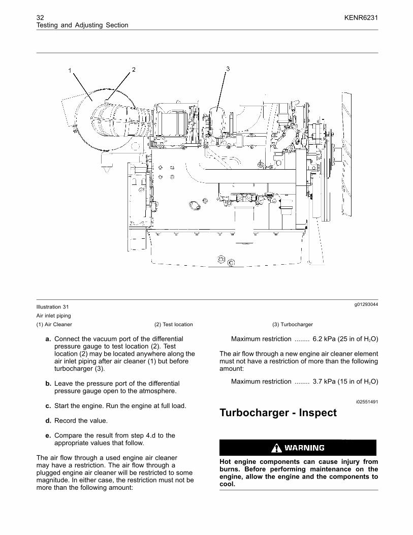
g01293044Illustration 31Air inlet piping(1) Air Cleaner (2) Test location (3) Turbocharger
a. Connect the vacuum port of the differentialpressure gauge to test location (2). Testlocation (2) may be located anywhere along theair inlet piping after air cleaner (1) but beforeturbocharger (3).
b. Leave the pressure port of the differentialpressure gauge open to the atmosphere.
c. Start the engine. Run the engine at full load.
d. Record the value.
e. Compare the result from step 4.d to theappropriate values that follow.
The air flow through a used engine air cleanermay have a restriction. The air flow through aplugged engine air cleaner will be restricted to somemagnitude. In either case, the restriction must not bemore than the following amount:
Maximum restriction ........ 6.2 kPa (25 in of H2O)
The air flow through a new engine air cleaner elementmust not have a restriction of more than the followingamount:
Maximum restriction ........ 3.7 kPa (15 in of H2O)
i02551491
Turbocharger - Inspect
Hot engine components can cause injury fromburns. Before performing maintenance on theengine, allow the engine and the components tocool.

KENR6231 33Testing and Adjusting Section
Personal injury can result from rotating and mov-ing parts.
Stay clear of all rotating and moving parts.
Never attempt adjustments while the machine ismoving or the engine is running unless otherwisespecified.
The machine must be parked on a level surfaceand the engine stopped.
NOTICEKeep all parts clean from contaminants.
Contaminants may cause rapid wear and shortenedcomponent life.
NOTICECare must be taken to ensure that fluids are containedduring performance of inspection, maintenance, test-ing, adjusting and repair of the product. Be prepared tocollect the fluid with suitable containers before open-ing any compartment or disassembling any compo-nent containing fluids.
Dispose of all fluids according to local regulations andmandates.
Before you begin inspection of the turbocharger,be sure that the inlet air restriction is within thespecifications for your engine. Be sure that theexhaust system restriction is within the specificationsfor your engine. Refer to Systems Operation, Testingand Adjusting, “Air Inlet and Exhaust System -Inspect”.
The condition of the turbocharger will have definiteeffects on engine performance. Use the followinginspections and procedures to determine thecondition of the turbocharger.
• Inspection of the Compressor and the CompressorHousing
• Inspection of the Turbine Wheel and the TurbineHousing
Inspection of the Compressor andthe Compressor HousingRemove air piping from the compressor inlet.
1. Inspect the compressor wheel for damage from aforeign object. If there is damage, determine thesource of the foreign object. As required, cleanthe inlet system and repair the intake system.Replace the turbocharger. If there is no damage,go to Step 3.
2. Clean the compressor wheel and clean thecompressor housing if you find buildup of foreignmaterial. If there is no buildup of foreign material,go to Step 3.
3. Turn the rotating assembly by hand. While youturn the assembly, push the assembly sideways .The assembly should turn freely. The compressorwheel should not rub the compressor housing.Replace the turbocharger if the compressor wheelrubs the compressor wheel housing. If there is norubbing or scraping, go to Step 4.
4. Inspect the compressor and the compressorwheel housing for oil leakage. An oil leak fromthe compressor may deposit oil in the aftercooler.Drain and clean the aftercooler if you find oil inthe aftercooler.
a. Check the oil level in the crankcase. If the oillevel is too high, adjust the oil level.
b. Inspect the air cleaner element for restriction. Ifrestriction is found, correct the problem.
c. Inspect the engine crankcase breather. Cleanthe engine crankcase breather or replacethe engine crankcase breather if the enginecrankcase breather is plugged.
d. Remove the oil drain line for the turbocharger.Inspect the drain opening. Inspect the oil drainline. Inspect the area between the bearings ofthe rotating assembly shaft. Look for oil sludge.Inspect the oil drain hole for oil sludge. Inspectthe oil drain line for oil sludge in the drainline. If necessary, clean the rotating assemblyshaft. If necessary, clean the oil drain hole. Ifnecessary, clean the oil drain line.
e. If Steps 4.a through 4.d did not reveal thesource of the oil leakage, the turbocharger hasinternal damage. Replace the turbocharger.
Inspection of the Turbine Wheeland the Turbine HousingRemove the air piping from the turbine housing.

34 KENR6231Testing and Adjusting Section
g00763164Illustration 32
Typical example(1) Turbine Housing(2) Turbine Wheel(3) Turbocharger
1. Inspect the turbine for damage by a foreign object.If there is damage, determine the source of theforeign object. Replace turbocharger (3). If thereis no damage, go to Step 2.
2. Inspect turbine wheel (2) for buildup of carbon andother foreign material. Inspect turbine housing (1)for buildup of carbon and foreign material. Cleanturbine wheel (2) and clean turbine housing (1) ifyou find buildup of carbon or foreign material. Ifthere is no buildup of carbon or foreign material,go to Step 3.
3. Turn the rotating assembly by hand. While youturn the assembly, push the assembly sideways.The assembly should turn freely. Turbine wheel (2)should not rub turbine wheel housing (1). Replaceturbocharger (3) if turbine wheel (2) rubs turbinehousing (1). If there is no rubbing or scraping, goto Step 4.
4. Inspect the turbine and turbine housing (1) for oilleakage. Inspect the turbine and turbine housing(1)for oil coking. Some oil coking may be cleaned.Heavy oil coking may require replacement ofthe turbocharger. If the oil is coming from theturbocharger center housing go to Step 4.a.Otherwise go to “Inspection of the Wastegate”.
a. Remove the oil drain line for the turbocharger.Inspect the drain opening. Inspect the areabetween the bearings of the rotating assemblyshaft. Look for oil sludge. Inspect the oil drainhole for oil sludge. Inspect the oil drain linefor oil sludge. If necessary, clean the rotatingassembly shaft. If necessary, clean the drainopening. If necessary, clean the drain line.
b. If crankcase pressure is high, or if the oil drainis restricted, pressure in the center housingmay be greater than the pressure of turbinehousing (1). Oil flow may be forced in the wrongdirection and the oil may not drain. Check thecrankcase pressure and correct any problems.
c. If the oil drain line is damaged, replace the oildrain line.
d. Check the routing of the oil drain line. Eliminateany sharp restrictive bends. Make sure thatthe oil drain line is not too close to the engineexhaust manifold.
e. If Steps 4.a through 4.d did not reveal thesource of the oil leakage, turbocharger (3) hasinternal damage. Replace turbocharger (3).
i02571444
Exhaust Temperature - Test
Table 9
Required Tools
Tool Part Number Part Description Qty
A - Infrared Thermometer 1
When the engine runs, the temperature of an exhaustmanifold port can indicate the condition of a fuelinjection nozzle.
A low temperature indicates that no fuel is flowing tothe cylinder. An inoperative fuel injection nozzle ora problem with the fuel injection pump could causethis low temperature.
A very high temperature can indicate that too muchfuel is flowing to the cylinder. A malfunctioningfuel injection nozzle could cause this very hightemperature.
Use the Tooling (A) to check exhaust temperature.

KENR6231 35Testing and Adjusting Section
i02571687
Engine Crankcase Pressure(Blowby) - Test
Table 10
Required Tools
ToolPart
Number Part Name Quantity
A - Pressure Gauge 1
Damaged pistons or rings can cause too muchpressure in the crankcase. This condition will causethe engine to run rough. There will be more than thenormal amount of fumes (blowby) rising from thecrankcase breather. The breather can then becomerestricted in a very short time, causing oil leakageat gaskets and seals that would not normally haveleakage. Blowby can also be caused by worn valveguides or by a failed turbocharger seal.
Install Tooling (A) to the most convenient location onthe output tube for the crankcase breather or thebreather hose. The pressure for the engine blowbyshould be 0.25 kPa (1 inch of H2O).
Note: Do not use the data alone to determine if theengine should be overhauled. Other indicators suchas high oil consumption, low power, hard starting,and excessive fuel consumption must be considered.
After a new engine is used for a short time, theblowby can decrease as the rings are seated. Newengines should be checked for blowby during allmaintenance checks. As the piston rings and cylinderwalls wear, the blowby will gradually increase.
The blowby on a worn engine may be two times ormore than the blowby of a new engine and mayindicate the need for an overhaul.
i02553372
Engine Valve Lash -Inspect/Adjust
To prevent possible injury, do not use the starterto turn the flywheel.
Hot engine components can cause burns. Allowadditional time for the engine to cool before mea-suring valve clearance.
This engine uses high voltage to control the fuelinjectors.
Disconnect electronic fuel injector enable circuitconnector to prevent personal injury.
Do not come in contact with the fuel injector ter-minals while the engine is running.
Note: Valve lash is measured between the rockerarm and the valve bridge. All measurements andadjustments must be made with the engine stoppedand the valves fully closed.
Valve Lash CheckAn adjustment is NOT NECESSARY if themeasurement of the valve lash is in the acceptablerange in Table 11.
Table 11
Inlet Valves Exhaust Valves
Valve Lash(StoppedEngine)
0.38 ± 0.08 mm(0.015 ± 0.003
inch)
0.76 ± 0.08 mm(0.030 ± 0.003 inch)
TCCompression
Stroke1-2-4 1-3-5
TC ExhaustStroke(1) 3-5-6 2-4-6
Firing Order 1-5-3-6-2-4(2)
(1) 360° from TC compression stroke(2) The No. 1 cylinder is at the front of the engine.
If the measurement is not within this range, anadjustment is necessary. Refer to “Valve LashAdjustment” for the proper procedure.

36 KENR6231Testing and Adjusting Section
Valve Lash Adjustment
g00935559Illustration 33Cylinder and valve location
(A) Exhaust valves(B) Inlet valves
Use the following procedure to adjust the valve lash:
1. Put the No. 1 piston at the top center positionon the compression stroke. Refer to SystemsOperation, Testing and Adjusting, “Finding TopCenter Position for No. 1 Piston”.
Table 12
CompressionStroke for No.1 Piston
Inlet Valves Exhaust Valves
Valve Lash0.38 ± 0.08 mm(0.015 ± 0.003
inch)
0.76 ± 0.08 mm(0.030 ± 0.003
inch)
Cylinders 1-2-4 1-3-5
2. Adjust the valve lash according to Table 12.
a. Lightly tap the rocker arm with a soft mallet.This will ensure that the lifter roller seatsagainst the camshaft’s base circle.
b. Loosen the adjustment locknut.
c. Place the appropriate feeler gauge betweenrocker arm and the valve bridge. Then, turnthe adjustment screw in a clockwise direction.Slide the feeler gauge between the rocker armand the valve bridge. Continue turning theadjustment screw until a slight drag is felt onthe feeler gauge. Remove the feeler gauge.
d. Tighten the adjustment locknut to a torqueof 30 ± 7 N·m (22 ± 5 lb ft). Do not allowthe adjustment screw to turn while you aretightening the adjustment locknut. Recheckthe valve lash after tightening the adjustmentlocknut.
Note: If necessary, adjust the electronic unit injectorson cylinders 3, 5 and 6. Refer to Systems Operation,Testing and Adjusting, “Electronic Unit Injector -Adjust” for the correct procedure.
3. Remove the timing pin. Turn the flywheel by 360degrees in the direction of engine rotation. Thiswill put the No. 6 piston at the top center positionon the compression stroke. Install the timing pin.
Table 13
CompressionStroke for No.6
PistonInlet Valves Exhaust Valves
Valve Lash0.38 ± 0.08 mm(0.015 ± 0.003
inch)
0.76 ± 0.08 mm(0.030 ± 0.003
inch)
Cylinders 3-5-6 2-4-6
4. Adjust the valve lash according to Table 13.
a. Lightly tap the rocker arm with a soft mallet.This will ensure that the lifter roller seatsagainst the camshaft’s base circle.
b. Loosen the adjustment locknut.
c. Place the appropriate feeler gauge betweenrocker arm and the valve bridge. Then, turnthe adjustment screw in a clockwise direction.Slide the feeler gauge between the rocker armand the valve bridge. Continue turning theadjustment screw until a slight drag is felt onthe feeler gauge. Remove the feeler gauge.
d. Tighten the adjustment locknut to a torqueof 30 ± 7 N·m (22 ± 5 lb ft). Do not allowthe adjustment screw to turn while you aretightening the adjustment locknut. Recheckthe valve lash after tightening the adjustmentlocknut.
5. Remove the timing bolt from the flywheel after alladjustments to the valve lash have been made.Reinstall the timing cover.
Refer to Systems Operation, Testing and Adjusting,“Electronic Unit Injector - Adjust”.

KENR6231 37Testing and Adjusting Section
Lubrication Systemi02571670
Engine Oil Pressure - Test
The engine oil pressure may be checkedelectronically by using the electronic service tool.The engine oil pressure can be measured with theelectronic service tool. Refer to Troubleshooting forinformation on the use of the electronic service tool.
Measuring Engine Oil Pressure
Work carefully around an engine that is running.Engine parts that are hot, or parts that are moving,can cause personal injury.
NOTICEKeep all parts clean from contaminants.
Contaminants may cause rapid wear and shortenedcomponent life.
NOTICECare must be taken to ensure that fluids are containedduring performance of inspection, maintenance, test-ing, adjusting and repair of the product. Be prepared tocollect the fluid with suitable containers before open-ing any compartment or disassembling any compo-nent containing fluids.
Dispose of all fluids according to local regulations andmandates.
Table 14
Required Tools
ToolPart
Number Part Name Quantity
A - Pressure Gauge 1
Tool (A) measures the oil pressure in the system.
g00977330Illustration 34
Oil gallery plug(1) Plug
1. Install Tool (A) into the oil gallery plugs (1).
Note: Engine oil pressure to the camshaft and mainbearings should be checked on each side of thecylinder block at oil gallery plugs (1).
2. Start the engine. Refer to Operation andMaintenance Manual, “Refill Capacities andRecommendations” for the recommendations ofengine oil.
3. Record the value of the engine oil pressure whenthe engine is at operating temperature 100 °C(212 °F).
The minimum engine oil pressure should beapproximately 275 to 414 kPa (40 to 59 psi).
4. Compare the recorded engine oil pressure withthe oil pressure indicators on the instrument paneland the engine oil pressure that is displayed onthe electronic service tool.
5. An engine oil pressure indicator that has a defector an engine oil pressure sensor that has a defectcan give a false indication of a low oil pressure ora high oil pressure. If there is a notable differencebetween the engine oil pressure readings makenecessary repairs.

38 KENR6231Testing and Adjusting Section
6. If low engine oil pressure is determined, refer to“Reasons for Low Engine Oil Pressure”.
7. If high engine oil pressure is determined, refer to“Reason for High Engine Oil Pressure”.
Reasons for Low Engine OilPressure
NOTICEKeep all parts clean from contaminants.
Contaminants may cause rapid wear and shortenedcomponent life.
NOTICECare must be taken to ensure that fluids are containedduring performance of inspection, maintenance, test-ing, adjusting and repair of the product. Be prepared tocollect the fluid with suitable containers before open-ing any compartment or disassembling any compo-nent containing fluids.
Dispose of all fluids according to local regulations andmandates.
• Engine oil level is low. Refer to Step 1.
• Engine oil is contaminated. Refer to Step 2.
• The engine oil bypass valves are open. Refer toStep 3.
• The engine lubrication system is open. Refer toStep 4.
• The oil pickup tube has a leak or a restricted inletscreen. Refer to Step 5.
• The engine oil pump is faulty. Refer to Step 6.
• Engine Bearings have excessive clearance. Referto Step 7.
1. Check the engine oil level in the crankcase. Theoil level can possibly be too far below the oil pumpsupply tube. This will cause the oil pump not tohave the ability to supply enough lubrication to theengine components. If the engine oil level is lowadd engine oil in order to obtain the correct engineoil level. Refer to Operation and MaintenanceManual, “Engine Oil” for the recommendations ofengine oil.
2. Engine oil that is contaminated with fuel or coolantwill cause low engine oil pressure. High engineoil level in the crankcase can be an indicationof contamination. Determine the reason forcontamination of the engine oil and make thenecessary repairs. Replace the engine oil with theapproved grade of engine oil. Refer to Operationand Maintenance Manual, “Engine Oil” for therecommendations of engine oil.
NOTICEPerkins oil filters are manufactured to Perkins speci-fications. Use of an oil filter that is not recommendedby Perkins could result in severe damage to the en-gine bearings, crankshaft, etc., as a result of the largerwaste particles from unfiltered oil entering the enginelubricating system. Only use oil filters recommendedby Perkins.
3. If the engine oil bypass valves are held in theopen position, a reduction in the oil pressure canbe the result. This may be due to debris in theengine oil. If the engine oil bypass valves arestuck in the open position, remove each engineoil bypass valve and clean each bypass valvein order to correct this problem. You must alsoclean each bypass valve bore. Install new engineoil filters. New engine oil filters will prevent moredebris from causing this problem. For informationon the repair of the engine oil bypass valves, referto Disassembly and Assembly, “Engine Oil FilterBase - Disassemble”.
4. An oil line or an oil passage that is open, broken,or disconnected will cause low engine oil pressure.An open lubrication system could be caused bya piston cooling jet that is missing or damaged.Determine the reason for an open lubricationsystem of the engine and make the necessaryrepairs.
Note: The piston cooling jets direct engine oil towardthe bottom of the piston in order to cool the piston.This also provides lubrication for the piston pin.Breakage, a restriction or incorrect installation of thepiston cooling jets will cause seizure of the piston.
5. The inlet screen of the oil pickup tube for theengine oil pump can have a restriction. Thisrestriction will cause cavitation and a loss ofengine oil pressure. Check the inlet screen onthe oil pickup tube and remove any material thatmay be restricting engine oil flow. Low engine oilpressure may also be the result of the oil pickuptube that is drawing in air. Check the joints of theoil pickup tube for cracks or a damaged O-ringseal. Remove the engine oil pan in order to gainaccess to the oil pickup tube and the oil screen.Refer to Disassembly and Assembly, “Engine OilPan - Remove and Install” for more information.

KENR6231 39Testing and Adjusting Section
6. Check the following problems that may occur tothe engine oil pump.
a. Air leakage in the supply side of the oil pumpwill also cause cavitation and loss of oilpressure. Check the supply side of the oil pumpand make necessary repairs. For informationon the repair of the engine oil pump, refer toDisassembly and Assembly, “Engine Oil Pump- Remove”.
b. Oil pump gears that have too much wear willcause a reduction in oil pressure. Repair theengine oil pump. For information on the repairof the engine oil pump, refer to Disassemblyand Assembly, “Engine Oil Pump - Remove”.
7. Excessive clearance at engine bearings willcause low engine oil pressure. Check theengine components that have excessive bearingclearance and make the necessary repairs.
Reason for High Engine OilPressure
NOTICEKeep all parts clean from contaminants.
Contaminants may cause rapid wear and shortenedcomponent life.
NOTICECare must be taken to ensure that fluids are containedduring performance of inspection, maintenance, test-ing, adjusting and repair of the product. Be prepared tocollect the fluid with suitable containers before open-ing any compartment or disassembling any compo-nent containing fluids.
Dispose of all fluids according to local regulations andmandates.
Engine oil pressure will be high if the engine oilbypass valves become stuck in the closed positionand the engine oil flow is restricted. Foreign matterin the engine oil system could be the cause for therestriction of the oil flow and the movement of theengine oil bypass valves. If the engine oil bypassvalves are stuck in the closed position, removeeach bypass valve and clean each bypass valve inorder to correct this problem. You must also cleaneach bypass valve bore. Install new engine oilfilters. New engine oil filters will prevent more debrisfrom causing this problem. For information on therepair of the engine oil filter bypass valve, refer toDisassembly and Assembly, “Engine Oil Filter Base -Disassemble”.
NOTICEPerkins oil filters are manufactured to Perkins speci-fications. Use of an oil filter that is not recommendedby Perkins could result in severe damage to the en-gine bearings, crankshaft, etc., as a result of the largerwaste particles from unfiltered oil entering the enginelubricating system. Only use oil filters recommendedby Perkins.
i02553373
Excessive Bearing Wear -Inspect
When some components of the engine show bearingwear in a short time, the cause can be a restriction inan oil passage.
An engine oil pressure indicator may show that thereis enough oil pressure, but a component is worndue to a lack of lubrication. In such a case, look atthe passage for the oil supply to the component.A restriction in an oil supply passage will not allowenough lubrication to reach a component. This willresult in early wear.
i02553374
Excessive Engine OilConsumption - Inspect
Engine Oil Leaks on the Outside ofthe EngineCheck for leakage at the seals at each end of thecrankshaft. Look for leakage at the gasket for theengine oil pan and all lubrication system connections.Look for any engine oil that may be leaking fromthe crankcase breather. This can be caused bycombustion gas leakage around the pistons. A dirtycrankcase breather will cause high pressure in thecrankcase. A dirty crankcase breather will cause thegaskets and the seals to leak.
Engine Oil Leaks into theCombustion Area of the CylindersEngine oil that is leaking into the combustion area ofthe cylinders can be the cause of blue smoke. Thereare several possible ways for engine oil to leak intothe combustion area of the cylinders:
• Leaks between worn valve guides and valve stems

40 KENR6231Testing and Adjusting Section
• Worn components or damaged components(pistons, piston rings, or dirty return holes for theengine oil)
• Incorrect installation of the compression ring and/orthe intermediate ring
• Leaks past the seal rings in the turbocharger shaft
• Overfilling of the crankcase
• Wrong dipstick or guide tube
Excessive consumption of engine oil can alsoresult if engine oil with the wrong viscosity is used.Engine oil with a thin viscosity can be caused by fuelleakage into the crankcase or by increased enginetemperature.
i02553375
Increased Engine OilTemperature - Inspect
If the oil temperature is high, then check for arestriction in the oil passages of the oil cooler. Arestriction in the oil cooler will not cause low oilpressure in the engine.
Determine if the oil cooler bypass valve is held in theopen position. This condition will allow the oil to passthrough the valve instead of the oil cooler. The oiltemperature will increase.
Refer to Operation and Maintenance Manual, “RefillCapacities” for the correct lubricating oil.

KENR6231 41Testing and Adjusting Section
Cooling Systemi02553376
Cooling System - Check(Overheating)
Above normal coolant temperatures can be causedby many conditions. Use the following procedureto determine the cause of above normal coolanttemperatures:
Personal injury can result from escaping fluid un-der pressure.
If a pressure indication is shown on the indicator,push the release valve in order to relieve pressurebefore removing any hose from the radiator.
1. Check the coolant level in the cooling system.Refer to Operation and Maintenance Manual,“Cooling System Coolant Level - Check”. If thecoolant level is too low, air will get into the coolingsystem. Air in the cooling system will cause areduction in coolant flow and bubbles in thecoolant. Air bubbles will keep coolant away fromthe engine parts, which will prevent the transfer ofheat to the coolant. Low coolant level is caused byleaks or incorrectly filling the radiator.
2. Check the mixture of antifreeze and water. Referto Operation and Maintenance Manual, “FluidRecommendations”. If the coolant mixture isincorrect, drain the system. Put the correct mixtureof water, antifreeze and coolant conditioner in thecooling system.
3. Check for air in the cooling system. Air can enterthe cooling system in different ways. The mostcommon causes of air in the cooling systemare not filling the cooling system correctly andcombustion gas leakage into the cooling system.Combustion gas can get into the system throughinside cracks, a damaged cylinder head, or adamaged cylinder head gasket. Air in the coolingsystem causes a reduction in coolant flow andbubbles in the coolant. Air bubbles keep coolantaway from the engine parts, which prevents thetransfer of heat to the coolant.
4. Check the water temperature gauge. A watertemperature gauge which does not work correctlywill not show the correct temperature. Referto Systems Operation, Testing and Adjusting,“Cooling System - Inspect”.
5. Check the sending unit. In some conditions, thetemperature sensor in the engine sends signalsto a sending unit. The sending unit converts thesesignals to an electrical impulse which is used by amounted gauge. If the sending unit malfunctions,the gauge can show an incorrect reading. Also ifthe electric wire breaks or if the electric wire shortsout, the gauge can show an incorrect reading.
6. Check the radiator.
a. Check the radiator for a restriction to coolantflow. Check the radiator for debris, dirt, ordeposits on the inside of the radiator core.Debris, dirt, or deposits will restrict the flow ofcoolant through the radiator.
b. Check for debris or damage between the finsof the radiator core. Debris between the finsof the radiator core restricts air flow throughthe radiator core. Refer to Systems Operation,Testing and Adjusting, “Cooling System -Inspect”.
c. Ensure that the radiator size is adequate forthe application. An undersized radiator doesnot have enough area for the effective releaseof heat. This may cause the engine to runat a temperature that is higher than normal.The normal temperature is dependent on theambient temperature.
7. Check the filler cap. A pressure drop in theradiator can cause the boiling point to be lower.This can cause the cooling system to boil. Referto Systems Operation, Testing and Adjusting,“Cooling System - Test”.
8. Check the fan and/or the fan shroud.
a. The fan must be large enough to send airthrough most of the area of the radiator core.Ensure that the size of the fan and the positionof the fan are adequate for the application.
b. The fan shroud must be the proper size andthe fan shroud must be positioned correctly.Ensure that the size of the fan shroud and theposition of the fan shroud are adequate for theapplication.
9. If the fan is belt driven, check for loose drive belts.A loose fan drive belt will cause a reduction in theair flow across the radiator. Check the fan drivebelt for proper belt tension. Adjust the tension ofthe fan drive belt, if necessary. Refer to SystemsOperation, Testing and Adjusting, “Belt TensionChart”.

42 KENR6231Testing and Adjusting Section
10.Check the cooling system hoses and clamps.Damaged hoses with leaks can normally be seen.Hoses that have no visual leaks can soften duringoperation. The soft areas of the hose can becomekinked or crushed during operation. These areasof the hose can cause a restriction in the coolantflow. Hoses become soft and/or get cracksafter a period of time. The inside of a hose candeteriorate, and the loose particles of the hosecan cause a restriction of the coolant flow. Referto Operation and Maintenance Manual, “Hosesand Clamps - Inspect/Replace”.
11.Check for a restriction in the air inlet system.A restriction of the air that is coming into theengine can cause high cylinder temperatures.High cylinder temperatures cause higher thannormal temperatures in the cooling system. Referto Systems Operation, Testing and Adjusting, “AirInlet and Exhaust System - Inspect”.
a. If the measured restriction is higher than themaximum permissible restriction, remove theforeign material from the engine air cleanerelement or install a new engine air cleanerelement. Refer to Operation and MaintenanceManual, “Engine Air Cleaner Element -Clean/Replace”.
b. Check for a restriction in the air inlet systemagain.
c. If the measured restriction is still higher thanthe maximum permissible restriction, check theair inlet piping for a restriction.
12.Check for a restriction in the exhaust system.A restriction of the air that is coming out of theengine can cause high cylinder temperatures.
a. Make a visual inspection of the exhaust system.Check for damage to exhaust piping or for adamaged muffler. If no damage is found, checkthe exhaust system for a restriction. Refer toSystems Operation, Testing and Adjusting, “AirInlet and Exhaust System - Inspect”.
b. If the measured restriction is higher than themaximum permissible restriction, there is arestriction in the exhaust system. Repair theexhaust system, as required.
13.Check the shunt line, if the shunt system isused. The shunt line must be submerged in theexpansion tank. A restriction of the shunt linefrom the radiator top tank to the engine waterpump inlet will cause a reduction in water pumpefficiency. A reduction in water pump efficiencywill result in low coolant flow and overheating.
14.Check the water temperature regulator. A watertemperature regulator that does not open, ora water temperature regulator that only openspart of the way can cause overheating. Refer toSystems Operation, Testing and Adjusting, “WaterTemperature Regulator - Test”.
15.Check the water pump. A water pump with adamaged impeller does not pump enough coolantfor correct engine cooling. Remove the waterpump and check for damage to the impeller. Referto Systems Operation, Testing and Adjusting,“Water Pump - Test”.
16.Check the air flow through the enginecompartment. The air flow through the radiatorcomes out of the engine compartment. Ensurethat the filters, air conditioner, and similar itemsare not installed in a way that prevents the freeflow of air through the engine compartment.
17.Check the aftercooler. A restriction of air flowthrough the air to air aftercooler (if equipped) cancause overheating. Check for debris or depositswhich would prevent the free flow of air throughthe aftercooler.
18.Consider high outside temperatures. Whenoutside temperatures are too high for the ratingof the cooling system, there is not enough of atemperature difference between the outside airand coolant temperatures.
19.Consider high altitude operation. The coolingcapacity of the cooling system goes down asthe engine is operated at higher altitudes. Apressurized cooling system that is large enough tokeep the coolant from boiling must be used.
i02553378
Cooling System - Inspect
Cooling systems that are not regularly inspected arethe cause for increased engine temperatures. Makea visual inspection of the cooling system before anytests are performed.
Personal injury can result from escaping fluid un-der pressure.
If a pressure indication is shown on the indicator,push the release valve in order to relieve pressurebefore removing any hose from the radiator.

KENR6231 43Testing and Adjusting Section
1. Check the coolant level in the cooling system.Refer to Operation and Maintenance Manual,“Cooling System Coolant Level - Check”.
2. Check the quality of the coolant. The coolantshould have the following properties:
• Color that is similar to new coolant
• Odor that is similar to new coolant
• Free from dirt and debris
If the coolant does not have these properties,drain the system and flush the system. Refillthe cooling system with the correct mixture ofwater, antifreeze, and coolant conditioner. Referto Operation and Maintenance Manual, “FluidRecommendations”.
3. Look for leaks in the system.
Note: A small amount of coolant leakage acrossthe surface of the water pump seals is normal. Thisleakage is required in order to provide lubrication forthis type of seal. A hole is provided in the water pumphousing in order to allow this coolant/seal lubricantto drain from the pump housing. Intermittent leakageof small amounts of coolant from this hole is not anindication of water pump seal failure.
4. Ensure that the air flow through the radiator doesnot have a restriction. Look for bent core finsbetween the folded cores of the radiator. Also, lookfor debris between the folded cores of the radiator.
5. Inspect the drive belts for the fan.
6. Check for damage to the fan blades.
7. Look for air or combustion gas in the coolingsystem.
8. Inspect the filler cap, and check the surface thatseals the filler cap. This surface must be clean.
i02553379
Cooling System - Test
This engine has a pressure type cooling system. Apressure type cooling system has two advantages.The cooling system can be operated in a safe mannerat a temperature higher than the normal boiling point(steam) of water.
This type of system prevents cavitation in the waterpump. Cavitation is the forming of low pressurebubbles in liquids that are caused by mechanicalforces. It is difficult to create a pocket of air in thistype of cooling system.
g00921815Illustration 35Boiling point of water
Remember that temperature and pressure worktogether. When a diagnosis is made of a coolingsystem problem, temperature and pressure must bechecked. Cooling system pressure will have an effecton the cooling system temperature. For an example,refer to Illustration 35. This will show the effect ofpressure on the boiling point (steam) of water. Thiswill also show the effect of height above sea level.
Personal injury can result from hot coolant, steamand alkali.
At operating temperature, engine coolant is hotand under pressure. The radiator and all linesto heaters or the engine contain hot coolant orsteam. Any contact can cause severe burns.
Remove filler cap slowly to relieve pressure onlywhen engine is stopped and radiator cap is coolenough to touch with your bare hand.
Cooling SystemConditioner contains alkali. Avoidcontact with skin and eyes.
The coolant level must be to the correct level in orderto check the coolant system. The engine must becold and the engine must not be running.
After the engine is cool, loosen the pressure capin order to relieve the pressure out of the coolingsystem. Then remove the pressure cap.
The level of the coolant should not be more than13 mm (0.5 inch) from the bottom of the filler pipe. Ifthe cooling system is equipped with a sight glass,the coolant should be to the proper level in the sightglass.

44 KENR6231Testing and Adjusting Section
Checking the Filler CapTable 15
Required Tools
Tool Part Number Part Description Qty
A GE50031 Pressurizing Pump 1
One cause for a pressure loss in the cooling systemcan be a damaged seal on the radiator filler cap.
g01096114Illustration 36
Typical schematic of filler cap(1) Sealing surface of both filler cap and radiator
Personal injury can result from hot coolant, steamand alkali.
At operating temperature, engine coolant is hotand under pressure. The radiator and all linesto heaters or the engine contain hot coolant orsteam. Any contact can cause severe burns.
Remove filler cap slowly to relieve pressure onlywhen engine is stopped and radiator cap is coolenough to touch with your bare hand.
Cooling SystemConditioner contains alkali. Avoidcontact with skin and eyes.
To check for the amount of pressure that opens thefiller cap, use the following procedure:
1. After the engine cools, carefully loosen the fillercap. Slowly release the pressure from the coolingsystem. Then, remove the filler cap.
Carefully inspect the filler cap. Look for anydamage to the seals and to the sealing surface.Inspect the following components for any foreignsubstances:
• Filler cap
• Seal
• Surface for seal
Remove any deposits that are found on theseitems, and remove any material that is found onthese items.
2. Install the filler cap onto Tooling (A).
3. Look at the gauge for the exact pressure thatopens the filler cap.
4. Compare the gauge reading with the openingpressure that is listed on the filler cap.
5. If the filler cap is damaged, replace the filler cap.
Testing The Radiator And CoolingSystem For LeaksTable 16
Required Tools
Tool Part Number Part Description Qty
A GE50031 Pressurizing Pump 1
Use the following procedure in order to check thecooling system for leaks:
Personal injury can result from hot coolant, steamand alkali.
At operating temperature, engine coolant is hotand under pressure. The radiator and all linesto heaters or the engine contain hot coolant orsteam. Any contact can cause severe burns.
Remove filler cap slowly to relieve pressure onlywhen engine is stopped and radiator cap is coolenough to touch with your bare hand.
Cooling SystemConditioner contains alkali. Avoidcontact with skin and eyes.
1. After the engine is cool, loosen the filler cap slowlyand allow pressure out of the cooling system.Then remove the filler cap from the radiator.
2. Ensure that the coolant level is above the top ofthe radiator core.
3. Install Tooling (A) onto the radiator.
4. Take the pressure reading on the gauge to 20 kPa(3 psi) more than the pressure on the filler cap.

KENR6231 45Testing and Adjusting Section
5. Check the radiator for leakage on the outside.
6. Check all connection points for leakage, andcheck the hoses for leakage.
The cooling system does not have leakage only if thefollowing conditions exist:.
• You do not observe any outside leakage.
• The reading remains steady after five minutes.
The inside of the cooling system has leakage only ifthe following conditions exist:
• The reading on the gauge goes down.
• You do NOT observe any outside leakage.
Make any repairs, as required.
Test For The Water TemperatureGaugeTable 17
Required Tools
Tool Part Number Part Description Qty
A - Thermometer 1
Personal injury can result from escaping fluid un-der pressure.
If a pressure indication is shown on the indicator,push the release valve in order to relieve pressurebefore removing any hose from the radiator.
Making contact with a running engine can causeburns from hot parts and can cause injury fromrotating parts.
When working on an engine that is running, avoidcontact with hot parts and rotating parts.
Check the accuracy of the water temperatureindicator or water temperature sensor if you findeither of the following conditions:
• The engine runs at a temperature that is too hot,but a normal temperature is indicated. A loss ofcoolant is found.
• The engine runs at a normal temperature, but ahot temperature is indicated. No loss of coolantis found.
Coolant temperature can also be read on the displayscreens of the Electronic Service Tool.
g01096115Illustration 37Typical example(1) Water manifold assembly
Remove a plug from water manifold assembly (1).Install Tooling (A) in the open port:
A temperature indicator of known accuracy can alsobe used to make this check.
Start the engine. Run the engine until the temperaturereaches the desired range according to the testthermometer. If necessary, place a cover over part ofthe radiator in order to cause a restriction of the airflow. The reading on the water temperature indicatorshould agree with the test thermometer within thetolerance range of the water temperature indicator.
i02553380
Water Temperature Regulator- Test
Personal injury can result from escaping fluid un-der pressure.
If a pressure indication is shown on the indicator,push the release valve in order to relieve pressurebefore removing any hose from the radiator.
1. Remove the water temperature regulator from theengine.

46 KENR6231Testing and Adjusting Section
2. Heat water in a suitable container until thetemperature is 98 °C (208 °F).
3. Hang the water temperature regulator in thecontainer of water. The water temperatureregulator must be below the surface of the waterand away from the sides and the bottom of thecontainer.
4. Keep the water at the correct temperature for tenminutes.
5. After ten minutes, remove the water temperatureregulator. Ensure that the water temperatureregulator is open.
Replace the water temperature regulator if thewater temperature regulator is not open at thespecified temperature. Refer to Specifications,“Water Temperature Regulator”.
i02553381
Water Pump - Test
Table 18
Required Tools
Tool Part Number Part Description Qty
A GE50033 Pressure Gauge 1
g01033819Illustration 38
Typical example(1) Water outlet(2) Port(3) Temperature regulator housing(4) Water pump(5) Port
Making contact with a running engine can causeburns from hot parts and can cause injury fromrotating parts.
When working on an engine that is running, avoidcontact with hot parts and rotating parts.
Perform the following procedure in order to determineif the water pump is operating correctly:
1. Remove the plug from port (2).
2. Install Tooling (A) in port (2).
3. Start the engine. Run the engine until the coolantis at operating temperature.
4. Note the water pump pressure. The water pumppressure should be 100 to 125 kPa (15 to 18 psi).

KENR6231 47Testing and Adjusting Section
Basic Enginei02553382
Piston Ring Groove - Inspect
Inspect the Piston and the PistonRings1. Check the piston for wear and other damage.
2. Check that the piston rings are free to move in thegrooves and that the rings are not broken.
Inspect the Clearance of the PistonRing1. Remove the piston rings and clean the groovesand the piston rings.
2. Fit new piston rings in the piston grooves.
3. Check the clearance for the piston ring by placinga suitable feeler gauge between the piston grooveand the top of piston ring. Refer to Specifications,“Piston and Rings” for the dimensions.
Inspect the Piston Ring End Gap1. Clean all carbon from the top of the cylinder bores.
2. Place each piston ring in the cylinder bore justbelow the cylinder ring ridge.
3. Use a suitable feeler gauge to measure pistonring end gap. Refer to Specifications, “Piston andRings” for the dimensions.
Note: The coil spring must be removed from the oilcontrol ring before the gap of the oil control ring ismeasured.
i02553391
Connecting Rod Bearings -Inspect
The connecting rod bearings fit tightly in the bore inthe rod. If the bearing joints are worn, check the boresize. This can be an indication of wear because ofa loose fit.
Connecting rod bearings are available with smallerinside diameters than the original size bearings.These bearings are for crankshafts that have beenground.
If necessary, replace the connecting rod bearings.Refer to Disassembly and Assembly, “ConnectingRod Bearings - Remove” and Disassembly andAssembly, “Connecting Rod Bearings - Install” for thecorrect procedure.
i02553396
Main Bearings - Inspect
Main bearings are available with smaller insidediameters than the original size bearings. Thesebearings are for crankshafts that have been ground.
If necessary, replace the main bearings. Referto Disassembly and Assembly, “Crankshaft MainBearings - Remove and Install” for the correctprocedure.
i02571419
Cylinder Block - Inspect
1. Clean all of the coolant passages and the oilpassages.
2. Check the cylinder block for cracks and damage.
3. The top deck of the cylinder block must not bemachined. This will affect the depth of the cylinderliner flange and the piston height above thecylinder block.
4. Check the front camshaft bearing for wear. Referto Specifications, “Camshaft Bearings” for thecorrect specification of the camshaft bearing. If anew bearing is needed, use a suitable adapter topress the bearing out of the bore. Ensure that theoil hole in the new bearing faces the front of theblock. The oil hole in the bearing must be alignedwith the oil hole in the cylinder block. The bearingmust be aligned with the face of the recess.

48 KENR6231Testing and Adjusting Section
i02553404
Cylinder Liner Projection -Inspect
Table 19
Required Tools
Tool Part Number Part Description Qty
A GE50005 Clamp bolt 6
B GE50006 Clamp washer 6
C GE50007 Fibre washer 6
D GE50002 Cylinder linerprojection tool 1
Note: The projection of the cylinder liner is measuredfrom the top of the cylinder liner to the top of thespacer plate.
g01096458Illustration 39Liner Projection Components(1) Bolt(2) Washer(3) Washer(4) Spacer plate(5) Cylinder liner(6) Block

KENR6231 49Testing and Adjusting Section
g00443044Illustration 40

50 KENR6231Testing and Adjusting Section
1. Ensure that the top face of the cylinder block (6)is clean. Install a new spacer plate gasket and aclean spacer plate.
2. Install the cylinder liners to the cylinder blockwithout seals or bands. Ensure that the cylinderliners are installed to the original positions.
3. Install Tooling (B) and Tooling (C) to Tooling (A).Refer to illustration 39.
4. Install Tooling (A) around the liner. Refer toillustration 39.
5. Tighten the bolts (6) to a torque of 95 N·m (70 lb ft).
6. Use Tooling (D) to measure the cylinder linerprojection at "A", "B", "C" and "D". Refer toillustration 40.
7. Record the measurements for the cylinder.
8. Repeat steps 3 to 7 for each cylinder.
9. Add the four readings for each cylinder. Divide thesum by four in order to find the average.
Table 20
Specifications
Liner Projection 0.025 to 0.152 mm(0.0010 to 0.0060 inch)
Maximum Variation InEach Liner 0.051 mm (0.0020 inch)
Maximum AverageVariation BetweenAdjacent Liners
0.051 mm (0.0020 inch)
Maximum VariationBetween All Liners 0.102 mm (0.0040 inch)
Note: If the liner projection changes around the liner,turn the liner to a new position within the bore. If theliner projection is not within specifications, move theliner to a different bore. Inspect the top face of thecylinder block.
If the cylinder liner projections are below 0.025 mm(0.0010 inch) or 0.051 mm (0.0020 inch) correctiveaction must be taken. A thinner spacer plate maybe used. The thinner spacer plate is available fromyour Perkins distributor. The plates are 0.076 mm(0.0030 inch) thinner than the original plate. Theplates will increase the liner projection. Use thesespacer plates to compensate for low liner projectionswhich are less than the 0.076 mm (0.0030 inch). Usethese spacer plates if inspection of the top face ofthe cylinder block reveals no measurable damagedirectly under the liner flanges but the average linerprojection is less than 0.076 mm (0.0030 inch).
Do not exceed the maximum liner projection of0.152 mm (0.006 inch). The excessive liner projectionwill contribute to cracking of the liner flange.
When the liner projection is correct, put a temporarymark on the liner and the spacer plate. Set the linersaside.
Note: Refer to Disassembly and Assembly, “CylinderLiner - Install” for the correct final installationprocedure for the cylinder liners.
i02553516
Flywheel - Inspect
Face Runout (Axial Eccentricity) ofthe FlywheelTable 21
Required Tools
Tool Part Number Part Description Qty
A 21825617 Dial Indicator Group 1
g00286049Illustration 41Checking face runout of the flywheel
1. Install Tooling (A). Refer to illustration 41. Alwaysput a force on the crankshaft in the same directionbefore the dial indicator is read. This will removeany crankshaft end clearance.
2. Set the dial indicator to read 0.0 mm (0.00 inch).

KENR6231 51Testing and Adjusting Section
3. Turn the flywheel at intervals of 45 degrees andread the dial indicator.
4. Take the measurements at all four points. Thedifference between the lower measurements andthe higher measurements that are performed atall four points must not be more than 0.15 mm(0.006 inch), which is the maximum permissibleface runout (axial eccentricity) of the flywheel.
Bore Runout (Radial Eccentricity)of the FlywheelTable 22
Required Tools
Tool Part Number Part Description Qty
A 21825617 Dial Indicator Group 1
g01278054Illustration 42Checking bore runout of the flywheel
1. Install Tooling (A). Refer to illustration 42.
2. Set the dial indicator to read 0.0 mm (0.00 inch).
3. Turn the flywheel at intervals of 45 degrees andread the dial indicator.
4. Take the measurements at all four points. Thedifference between the lower measurements andthe higher measurements that are performed atall four points must not be more than 0.15 mm(0.006 inch) for the maximum permissible facerunout (radial eccentricity) of the flywheel.
g00286058Illustration 43Flywheel clutch pilot bearing bore
5. To find the runout (eccentricity) of the pilot bearingbore, use the preceding procedure.
6. The runout (eccentricity) of the bore for the pilotbearing in the flywheel must not exceed 0.13 mm(0.005 inch).
i02553531
Flywheel Housing - Inspect
Table 23
Required Tools
Tool Part Number Part Description Qty
A 21825617 Dial Indicator Group 1
Face Runout (Axial Eccentricity) ofthe Flywheel Housing
g00285931Illustration 44
Typical example
If you use any other method except the method thatis given here, always remember that the bearingclearance must be removed in order to receive thecorrect measurements.

52 KENR6231Testing and Adjusting Section
1. Install Tooling (A) to the flywheel so the anvil of thedial indicator will contact the face of the flywheelhousing. Refer to illustration 44.
2. Use a rubber mallet and tap the crankshaft towardthe rear before the dial indicator is read at eachpoint.
g00285932Illustration 45
Checking face runout of the flywheel housing
3. Turn the flywheel while the dial indicator is set at0.0 mm (0.00 inch) at location (A). Read the dialindicator at locations (B), (C) and (D).
4. The difference between the lower measurementsand the higher measurements that are performedat all four points must not be more than 0.38 mm(0.015 inch), which is the maximum permissibleface runout (axial eccentricity) of the flywheelhousing.
Bore Runout (Radial Eccentricity)of the Flywheel Housing
g00285934Illustration 46Typical example
1. Install Tooling (A) to the flywheel so the anvil of thedial indicator will contact the bore of the flywheelhousing. Refer to illustration 46.
g00285932Illustration 47Checking bore runout of the flywheel housing
g00763974Illustration 48
2. While the dial indicator is in the position at location(C) adjust the dial indicator to 0.0 mm (0.00 inch).Push the crankshaft upward against the top ofthe bearing. Refer to Illustration 48. Write themeasurement for bearing clearance on line 1 incolumn (C).
Note: Write the measurements for the dial indicatorwith the correct notations. This notation is necessaryfor making the calculations in the chart correctly.
3. Divide the measurement from Step 2 by two. Writethis number on line 1 in columns (B) and (D).
4. Turn the flywheel in order to put the dial indicatorat position (A). Adjust the dial indicator to 0.0 mm(0.00 inch).
5. Turn the flywheel counterclockwise in order toput the dial indicator at position (B). Write themeasurements in the chart.
6. Turn the flywheel counterclockwise in order toput the dial indicator at position (C). Write themeasurement in the chart.

KENR6231 53Testing and Adjusting Section
7. Turn the flywheel counterclockwise in order toput the dial indicator at position (D). Write themeasurement in the chart.
8. Add the lines together in each column.
9. Subtract the smaller number from the largernumber in column B and column D. Place thisnumber on line III. The result is the horizontaleccentricity (out of round). Line III in column C isthe vertical eccentricity.
g00286046Illustration 49
Graph for total eccentricity(1) Total vertical eccentricity(2) Total horizontal eccentricity(3) Acceptable value(4) Unacceptable value
10. Find the intersection of the eccentricity lines(vertical and horizontal) in Illustration 49.
11. If the point of the intersection is in the “Acceptable”range, the bore is in alignment. If the point ofintersection is in the “Not acceptable” range, theflywheel housing must be changed.
i02553546
Vibration Damper - Check
g01287000Illustration 50
(1) Adapter(2) Vibration damper(3) Bolts(4) Crankshaft pulley
Damage to the vibration damper or failure of thevibration damper will increase vibrations. This willresult in damage to the crankshaft.
Replace the damper if any of the following conditionsexist:
• The damper is dented, cracked, or fluid is leakingfrom the damper.
• The paint on the damper is discolored fromexcessive heat.
• The damper is bent.
• The bolt holes are worn or there is a loose fit forthe bolts.
• The engine has had a crankshaft failure due totorsional forces.
NOTICEInspect the viscous vibration damper for signs of leak-ing and for signs of damage to the case. Either ofthese conditions can cause the weight to contact thecase. This contact can affect damper operation.

54 KENR6231Testing and Adjusting Section
Electrical Systemi02555153
Battery - Test
Most of the tests of the electrical system can be doneon the engine. The wiring insulation must be in goodcondition. The wire and cable connections must beclean, and both components must be tight.
Never disconnect any charging unit circuit or bat-tery circuit cable from the battery when the charg-ing unit is operated. A spark can cause an explo-sion from the flammable vapor mixture of hydro-gen and oxygen that is released from the elec-trolyte through the battery outlets. Injury to per-sonnel can be the result.
The battery circuit is an electrical load on the chargingunit. The load is variable because of the condition ofthe charge in the battery.
NOTICEThe charging unit will be damaged if the connectionsbetween the battery and the charging unit are brokenwhile the battery is being charged. Damage occursbecause the load from the battery is lost and becausethere is an increase in charging voltage. High voltagewill damage the charging unit, the regulator, and otherelectrical components.
See Special Instruction, SEHS7633, “Battery TestProcedure” for the correct procedures to use totest the battery. This publication also contains thespecifications to use when you test the battery.
i02554905
Charging System - Test
The condition of charge in the battery at eachregular inspection will show if the charging system isoperating correctly. An adjustment is necessary whenthe battery is constantly in a low condition of chargeor a large amount of water is needed. A large amountof water would be more than one ounce of water pera cell per a week or per every 100 service hours.
When it is possible, make a test of the chargingunit and voltage regulator on the engine, and usewiring and components that are a permanent part ofthe system. Off-engine testing or bench testing willgive a test of the charging unit and voltage regulatoroperation. This testing will give an indication ofneeded repair. After repairs are made, perform a testin order to prove that the units have been repaired tothe original condition of operation.
Test Tools For The ChargingSystem
g01012117Illustration 51Typical example of an ammeter
The ammeter is a self-contained instrument thatmeasures electrical currents without breakingthe circuit and without disturbing the conductor’sinsulation.
The ammeter contains a digital display that is usedto monitor current directly within a range between 1ampere and 1200 amperes. The multimeter shouldbe used under only one condition:
• the readings are less than 1 ampere.
A lever opens the ammeter’s jaws over a conductor.The conductor’s diameter can not be larger than19 mm (0.75 inch).
The spring loaded jaws close around the conductorfor measuring the current. A trigger switch controlsthe ammeter. The trigger switch can be locked intothe ON position or into the OFF position.
After the trigger has been working and the trigger isturned to the OFF position, the reading appears inthe digital display for five seconds. This accuratelymeasures currents in areas with a limited access.For example, these areas include areas that arebeyond the operator’s sight. For DC operation, anammeter contains a zero control, and batteries insidethe handle supply the power.

KENR6231 55Testing and Adjusting Section
g00283566Illustration 52Typical example of a digital multimeter
i02554920
Electric Starting System - Test
Most of the tests of the electrical system can bedone on the engine. The wiring insulation must bein good condition. The wire and cable connectionsmust be clean, and both components must be tight.The battery must be fully charged. If the on-enginetest shows a defect in a component, remove thecomponent for more testing.
The starting system consists of the following fourcomponents:
• Keyswitch
• Start relay
• Starting motor solenoid
• Starting motor
Trouble with the starting system could be causedby the battery or by charging system problems. Ifthe battery is suspect, refer to Troubleshooting,“Battery”. If the starting system is suspect, refer toTroubleshooting, “Engine Will Not Crank”.

56 KENR6231Index Section
Index
A
Air in Fuel - Test..................................................... 23Air Inlet and Exhaust System .......................... 12, 31Turbocharger ..................................................... 13Valves And Valve Mechanism............................ 13
Air Inlet and Exhaust System - Inspect.................. 31Air Inlet Restriction............................................. 31
B
Basic Engine.................................................... 17, 47Camshaft............................................................ 18Crankshaft.......................................................... 18Cylinder Block Assembly ................................... 17Cylinder Head Assembly.................................... 18Pistons, Rings And Connecting Rods ................ 18
Battery - Test ......................................................... 54Belt Tension Chart ................................................. 22
C
Charging System - Test ......................................... 54Test Tools For The Charging System................. 54
Connecting Rod Bearings - Inspect....................... 47Cooling System ............................................... 16, 41Cooling System - Check (Overheating) ................. 41Cooling System - Inspect....................................... 42Cooling System - Test............................................ 43Checking the Filler Cap...................................... 44Test For The Water Temperature Gauge ........... 45Testing The Radiator And Cooling System ForLeaks................................................................ 44
Cylinder Block - Inspect......................................... 47Cylinder Liner Projection - Inspect......................... 48
E
Electric Starting System - Test............................... 55Electrical System............................................. 18, 54Charging System Components .......................... 19Engine Electrical System ................................... 19Grounding Practices .......................................... 18Starting System Components ............................ 20
Electronic Control System Components.................. 6Electronic Unit Injector - Adjust ............................. 24Electronic Unit Injector - Test................................. 24Engine Crankcase Pressure (Blowby) - Test ......... 35Engine Oil Pressure - Test..................................... 37Measuring Engine Oil Pressure ......................... 37Reason for High Engine Oil Pressure ................ 39Reasons for Low Engine Oil Pressure ............... 38
Engine Valve Lash - Inspect/Adjust ....................... 35Valve Lash Adjustment ...................................... 36Valve Lash Check .............................................. 35
Excessive Bearing Wear - Inspect......................... 39Excessive Engine Oil Consumption - Inspect........ 39Engine Oil Leaks into the Combustion Area of theCylinders .......................................................... 39Engine Oil Leaks on the Outside of the Engine.. 39
Exhaust Temperature - Test................................... 34
F
Finding Top Center Position for No. 1 Piston......... 25Flywheel - Inspect.................................................. 50Bore Runout (Radial Eccentricity) of theFlywheel ........................................................... 51Face Runout (Axial Eccentricity) of theFlywheel ........................................................... 50
Flywheel Housing - Inspect ................................... 51Bore Runout (Radial Eccentricity) of the FlywheelHousing ............................................................ 52Face Runout (Axial Eccentricity) of the FlywheelHousing ............................................................ 51
Fuel Quality - Test.................................................. 26Fuel System....................................................... 8, 23Electronic Unit Injector ........................................ 11Electronic Unit Injector Mechanism.................... 10Fuel System Electronic Control Circuit ................ 9
Fuel System - Inspect............................................ 23Fuel System - Prime.............................................. 26Fuel System Pressure - Test ................................. 27Checking Fuel Pressure..................................... 28Fuel Pressure Readings .................................... 28High Fuel Pressure ............................................ 27Low Fuel Pressure ............................................. 27
G
Gear Group (Front) - Time..................................... 28Setting Backlash For Camshaft And AdjustableIdler Gear ......................................................... 29
General Information................................................. 4Cold Mode Operation........................................... 5Starting the Engine .............................................. 5
I
Important Safety Information ................................... 2Increased Engine Oil Temperature - Inspect ......... 40
L
Lubrication System.......................................... 14, 37Lubrication System Components ....................... 14Oil Flow In The Engine....................................... 16

KENR6231 57Index Section
M
Main Bearings - Inspect......................................... 47
P
Piston Ring Groove - Inspect................................. 47Inspect the Clearance of the Piston Ring........... 47Inspect the Piston and the Piston Rings ............ 47Inspect the Piston Ring End Gap....................... 47
S
Systems Operation Section ..................................... 4
T
Table of Contents..................................................... 3Testing and Adjusting ............................................ 22Testing and Adjusting Section ............................... 22Turbocharger - Inspect .......................................... 32Inspection of the Compressor and the CompressorHousing ............................................................ 33Inspection of the Turbine Wheel and the TurbineHousing ............................................................ 33
V
Vibration Damper - Check ..................................... 53
W
Water Pump - Test................................................. 46Water Temperature Regulator - Test ..................... 45

58 KENR6231Index Section

KENR6231 59Index Section

Copyright © 200 5 Perkins Engines Company LimitedAll Rights Reserved Printed in U.K.