summer– 17 examination subject code: 17307msbte.engg-info.website/sites/default/files/s17mo...
TRANSCRIPT

MAHARASHTRA STATE BOARD OF TECHNICAL EDUCATION (Autonomous) (ISO/IEC - 27001 - 2005 Certified) __________________________________________________________________________________________________
Page No:1/25
MODEL ANSWER SUMMER– 17 EXAMINATION Subject Title: Vehicle Layout and Transmission System Subject Code:
Important Instructions to examiners: 1) The answers should be examined by key words and not as word-to-word as given in the model answer
scheme. 2) The model answer and the answer written by candidate may vary but the examiner may try to assess the
understanding level of the candidate. 3) The language errors such as grammatical, spelling errors should not be given more Importance (Not
applicable for subject English and Communication Skills. 4) While assessing figures, examiner may give credit for principal components indicated in the figure. The
figures drawn by candidate and model answer may vary. The examiner may give credit for any equivalent figure drawn.
5) Credits may be given step wise for numerical problems. In some cases, the assumed constant values may vary and there may be some difference in the candidate’s answers and model answer.
6) In case of some questions credit may be given by judgement on part of examiner of relevant answer based on candidate’s understanding.
7) For programming language papers, credit may be given to any other program based on equivalent concept.
Q. No.
Sub Q. N.
Answer Marking Scheme
1A) Attempt any SIX. (6x2) 12
a) What is meant by vehicle layout? Give any two examples of layout. 02
Answer : Vehicle Layout-
Vehicle layout is a systematic arrangement of different units which consists of engine, followed by clutch, gearbox, propeller shaft, universal joints, differential and axles that are fitted on the frame. The layout of a vehicle shows the location or position of the main parts used in vehicle performing different required functions.
Example-(any two example)
1) Front engine front wheel drive
2) Front engine rear wheel drive
3) Four wheel drive
4) Rear engine rear wheel drive
01
01
b) State the necessity of frame. 02
Answer: Necessity of the Frame
1. To support the body and chassis components such as engine, gear box, axles, suspension
02
17307

MAHARASHTRA STATE BOARD OF TECHNICAL EDUCATION (Autonomous) (ISO/IEC - 27001 - 2005 Certified) __________________________________________________________________________________________________
Page No:2/25
system, braking system etc.
2. To withstand different types of loads acting on it.
c) Why fame is narrow at the front? 02
Answer: The Frame is narrow at the front-
1. To have a better steering lock.
2. It gives smaller turning circle radius.
02
d) State the working principle of automobile clutch. 02
Answer: Working principle of automobile clutch
It works on the principle of friction. It connects the engine shaft and gear box shaft. The transmission of power can be affected by friction between two or more, rotating concentric surfaces, called as friction plate. The friction plates can be pressed firmly against one another by means of axial force provided by spring and pressure plate. When it engaged, the clutch tends to rotate as a single unit. The rotating speed of the concentric surface or other shaft is depends upon the friction force which is proportional to axial force applied by spring.
02
e) State the principle of operation of gear box. 02
Answer: Principle of operation of gear box –
In a gear box, the counter shaft is mashed to the clutch with a use of a couple of gear. So the counter shaft is always in running condition. When the counter shaft is bring in contact with the main shaft by use of meshing gears, the main shaft start to rotate according to the gear ratio. When want to change the gear ratio, simply press the clutch pedal which disconnect the counter shaft with engine and change connect the main shaft with counter shaft by another gear ratio by use of gearshift lever. In a gear box, the gear teeth and other moving metal must not touch. They must be continuously separated by a thin film of lubricant. This prevents excessive wear and early failure. Therefore a gearbox runs partially filled with lubricant oil.
02
f) Give the function of universal joint and slip joint. 02
Answer: Function of Universal Joint- Universal joint allows transmission of power and rotary motion at an angle which varies as a vehicle encounters a bump. Function of Slip Joint- It is provided at the gearbox end, this joint allows variation in length of the propeller shaft.
01
01
g) What is meant by double reduction axle? 02
Answer: Double Reduction Axle- In this type of axle the drive speed is reduced in two separate steps. The bevel pinion is driven by the propeller shaft and then drive is passed to the small crown wheel which is fixed to a layshaft, on which is also fixed a spur pinion. The spur pinion meshes with a large spur wheel
02

MAHARASHTRA STATE BOARD OF TECHNICAL EDUCATION (Autonomous) (ISO/IEC - 27001 - 2005 Certified) __________________________________________________________________________________________________
Page No:3/25
which is attached to the differential casing just at the crown wheel of a single reduction axle. Thus the final drive is transmitted to the axle shaft.
h) State the various types of loads acting on rear axle. 02
Answer: The various loads acting on the rear axle are-(Any 02 points each carry 01 mark) 1) Driving thrust-Driving torque produced in the engine causes the thrust to be produced in the road wheels, which has to be transmitted from the axle casing to the chassis frame and the body of the vehicle. 2) Torque Reaction-If the rear axle is held rigidly when the road wheels are prevented from rotation, (due to driving needs or road conditions) the bevel pinion of the final drive tends to rotate around the crown wheel. It produces a tendency in the whole vehicle to rotate about the rear axle, or to lift off the front of the vehicle. This effect is known as torque –reaction. 3) Braking torque or thrust-The axle casing experiences the brake torque when the brakes are applied to the vehicle. 4) Side thrust-When the vehicle is taking the turn, the rear axle subjected to the side thrust or pulls due to any side load on the wheel. 5) Weight of the body-The rear axle may be considered a beam supported at ends loaded. This weight causes bending and shears force in the axle shaft.
02
1B) Attempt any TWO. (4x2) 08
a) State the types of frame used in four wheeler. Explain any one with neat sketch. 04
Answer: Types of four wheeler frame: The common types of four wheeler chassis frame are- A. Conventional Frame B. Half Integral and Half Frame C. Integral or Unitized construction (Frameless Construction)
1. Conventional frame: It has two long side members and 5 to 6 cross members joined together with the help of rivets and bolts. The frame sections are used generally.
a. Channel Section – Good resistance to bending
b. Tabular Section – Good resistance to Torsion
c. Box Section – Good resistance to both bending and Torsion.
01
01

MAHARASHTRA STATE BOARD OF TECHNICAL EDUCATION (Autonomous) (ISO/IEC - 27001 - 2005 Certified) __________________________________________________________________________________________________
Page No:4/25
(Equivalent Credit shall be given for suitable sketch) OR
2. Integral Frame: This frame is used now a day in most of the cars. There is no frame and all the assembly units are attached to the body. All the functions of the frame carried out by the body itself. Due to elimination of long frame it is cheaper and due to less weight most economical also. Only disadvantage is repairing is difficult.
(Equivalent Credit shall be given for suitable sketch)
3. Semi – Integral Frame: In some vehicles half frame is fixed in the front end on which engine gear box and front suspension is mounted. It has the advantage when the vehicle is met with accident the front frame can be taken easily to replace the damaged chassis frame. This type of frame is used in some of the European and American cars.
02
01
02
01

MAHARASHTRA STATE BOARD OF TECHNICAL EDUCATION (Autonomous) (ISO/IEC - 27001 - 2005 Certified) __________________________________________________________________________________________________
Page No:5/25
(Equivalent Credit shall be given for suitable sketch)
02
b) Compare dry and wet clutch (any four points). 04
Answer: Comparison of dry and wet clutch (any four points)
04
MAHARASHTRA STATE BOARD OF TECHNICAL EDUCATION (Autonomous) (ISO/IEC - 27001 - 2005 Certified) __________________________________________________________________________________________________
Page No:6/25
c) Explain the working of “Variator drive” with neat sketch. 04
Answer :
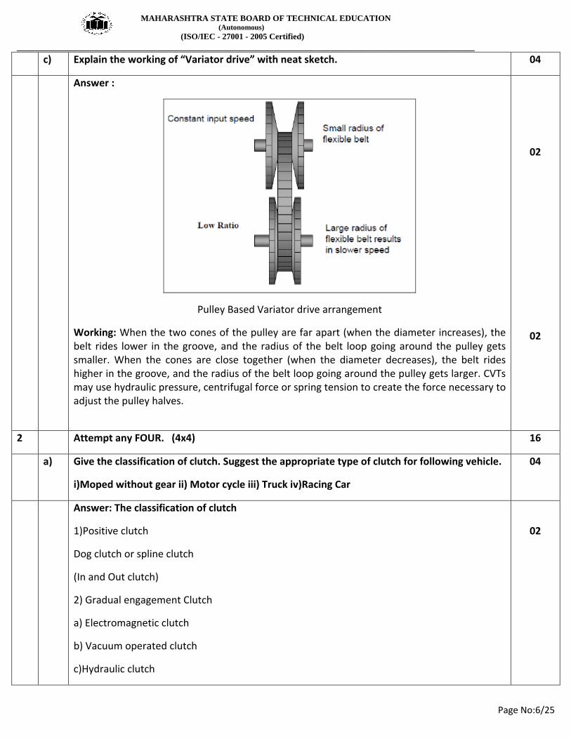
Pulley Based Variator drive arrangement
Working: When the two cones of the pulley are far apart (when the diameter increases), the belt rides lower in the groove, and the radius of the belt loop going around the pulley gets smaller. When the cones are close together (when the diameter decreases), the belt rides higher in the groove, and the radius of the belt loop going around the pulley gets larger. CVTs may use hydraulic pressure, centrifugal force or spring tension to create the force necessary to adjust the pulley halves.
02
02
2 Attempt any FOUR. (4x4) 16
a) Give the classification of clutch. Suggest the appropriate type of clutch for following vehicle.
i)Moped without gear ii) Motor cycle iii) Truck iv)Racing Car
04
Answer: The classification of clutch
1)Positive clutch
Dog clutch or spline clutch
(In and Out clutch)
2) Gradual engagement Clutch
a) Electromagnetic clutch
b) Vacuum operated clutch
c)Hydraulic clutch
02

MAHARASHTRA STATE BOARD OF TECHNICAL EDUCATION (Autonomous) (ISO/IEC - 27001 - 2005 Certified) __________________________________________________________________________________________________
Page No:7/25
d) Fluid clutch or Fluid flywheel clutch
e) Friction clutch
i) Cone clutch (Internal and External)
ii)Disc Plate clutch (Single plate and Multi Plate)
iii) Semi centrifugal clutch
iv) Diaphragm or conical spring clutch (Taper finger and crown spring)
v) Centrifugal clutch
The appropriate type of clutch for following vehicle
i)Moped without gear- Centrifugal clutch
ii)Motor cycle – Multiplate clutch
iii) Truck- Single plate clutch
iv) Racing car – cone clutch
02
(1/2 half
mark for
each)
b) Explain operating mechanism in cable operated clutch with neat sketch. 04
Answer: Operating Mechanism in Cable operated clutch - Cable linkage is a popular and effective method of transferring movement from the pedal to the clutch. The cable assembly uses an inner multi-strand steel-wire core and an outer cable sheath of a spiral wound flexible sleeve normally with nylon end-pieces. A screw adjustment is incorporated at either the pedal or the bell-housing end to alter the length of the outer cable sleeve, for increasing or decreasing the free-play of the inner cable. From the cable the leverage is relayed through a pressed steel release-fork lever to the thrust bearing. A spherical headed bolt pivots the lever end. The outer end of the lever extends outside the bell-housing and is connected to the inner cable. When the clutch is disengaged, the inner cable is subjected to tension and the outer sleeve into compression. The fork-lever then tilts about its pivot forcing the release bearing against the release-fingers to disengage the drive.
02

MAHARASHTRA STATE BOARD OF TECHNICAL EDUCATION (Autonomous) (ISO/IEC - 27001 - 2005 Certified) __________________________________________________________________________________________________
Page No:8/25
Labelled
Sketch- 2 marks
c) Explain the working of multiplate clutch with neat sketch. 04
Answer: Working of multiplate clutch - While the flywheel is rotating the pressure plates rotate and press against the friction plate. This causes the friction plates and thus the clutch shaft to rotate as well. When the pedal is pressed, the flywheel continues to rotate but the friction plates are released. This happens because they are not fully pressed by pressure plates. Thus the shaft also stops rotating.
02
Labelled
Sketch- 2 marks
d) Explain hydraulic operated clutch mechanism with neat sketch. 04
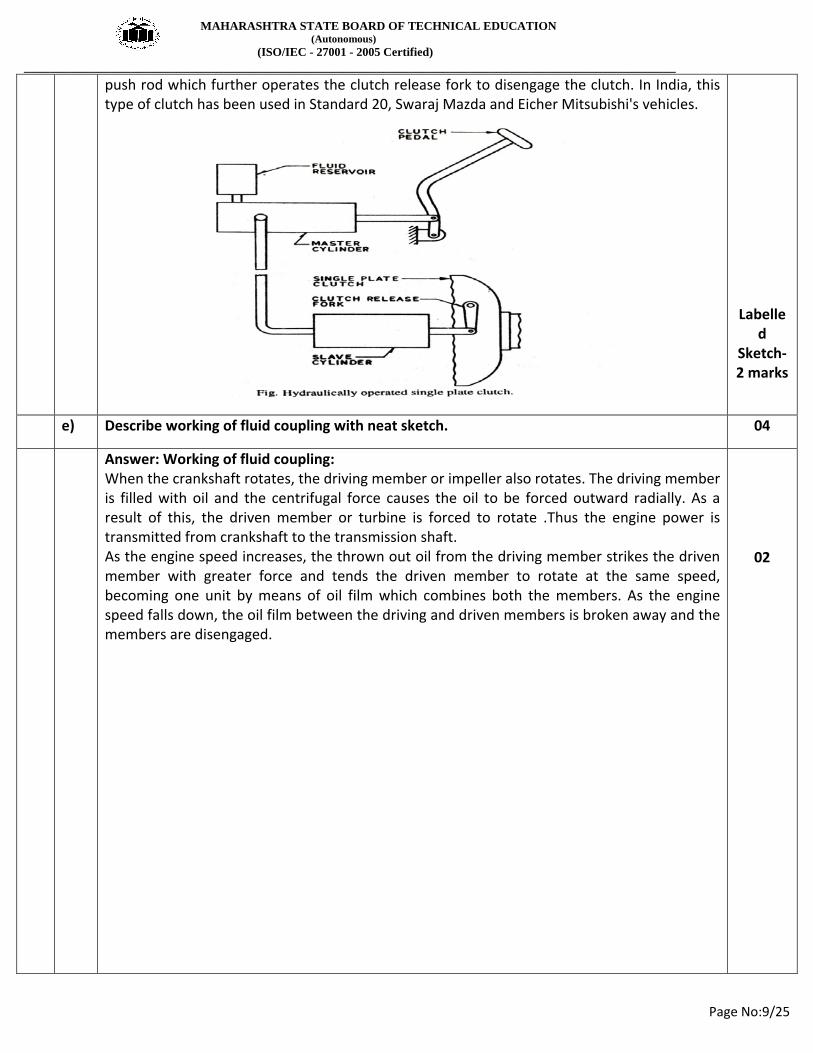
Answer: Hydraulic Operated Clutch Mechanism- A hydraulically operated clutch mechanism is shown in the figure. The mechanism consists of master and slave cylinders. The cylinders are connected by hydraulic lines. When the clutch pedal is pressed the fluid under pressure from the master cylinder reaches the slave cylinder which is mounted on the clutch itself. The fluid under pressure actuates the slave cylinder
02
MAHARASHTRA STATE BOARD OF TECHNICAL EDUCATION (Autonomous) (ISO/IEC - 27001 - 2005 Certified) __________________________________________________________________________________________________
Page No:9/25
push rod which further operates the clutch release fork to disengage the clutch. In India, this type of clutch has been used in Standard 20, Swaraj Mazda and Eicher Mitsubishi's vehicles.
Labelled
Sketch- 2 marks
e) Describe working of fluid coupling with neat sketch. 04
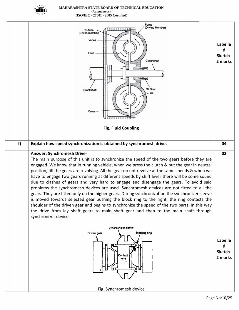
Answer: Working of fluid coupling: When the crankshaft rotates, the driving member or impeller also rotates. The driving member is filled with oil and the centrifugal force causes the oil to be forced outward radially. As a result of this, the driven member or turbine is forced to rotate .Thus the engine power is transmitted from crankshaft to the transmission shaft. As the engine speed increases, the thrown out oil from the driving member strikes the driven member with greater force and tends the driven member to rotate at the same speed, becoming one unit by means of oil film which combines both the members. As the engine speed falls down, the oil film between the driving and driven members is broken away and the members are disengaged.
02
MAHARASHTRA STATE BOARD OF TECHNICAL EDUCATION (Autonomous) (ISO/IEC - 27001 - 2005 Certified) __________________________________________________________________________________________________
Page No:10/25
Fig. Fluid Coupling
Labelled
Sketch- 2 marks
f) Explain how speed synchronization is obtained by synchromesh drive. 04
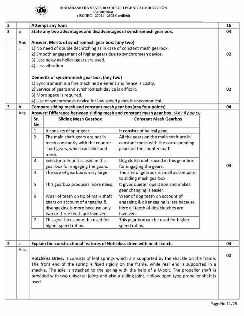
Answer: Synchromesh Drive- The main purpose of this unit is to synchronize the speed of the two gears before they are engaged. We know that in running vehicle, when we press the clutch & put the gear in neutral position, till the gears are revolving. All the gear do not revolve at the same speeds & when we have to engage two gears running at different speeds by shift lever there will be some sound due to clashes of gears and very hard to engage and disengage the gears. To avoid said problems the synchromesh devices are used. Synchromesh devices are not fitted to all the gears. They are fitted only on the higher gears. During synchronization the synchronizer sleeve is moved towards selected gear pushing the block ring to the right, the ring contacts the shoulder of the driven gear and begins to synchronize the speed of the two parts. In this way the drive from lay shaft gears to main shaft gear and then to the main shaft through synchronizer device.
Fig. Synchromesh device
02
Labelled
Sketch- 2 marks
MAHARASHTRA STATE BOARD OF TECHNICAL EDUCATION (Autonomous) (ISO/IEC - 27001 - 2005 Certified) __________________________________________________________________________________________________
Page No:11/25
3 Attempt any four: 16 3 a State any two advantages and disadvantages of synchromesh gear box. 04
Ans.
Answer: Merits of synchromesh gear box: (any two) 1) No need of double declutching as in case of constant mesh gearbox. 2) Smooth engagement of higher gears due to synchromesh device. 3) Less noisy as helical gears are used. 4) Less vibration. Demerits of synchromesh gear box: (any two) 1) Synchromesh is a fine machined element and hence is costly. 2) Service of gears and synchromesh device is difficult. 3) More space is required. 4) Use of synchromesh device for low speed gears is uneconomical.
02
02
3 b Compare sliding mesh and constant mesh gear box(any four points) 04 Ans. Answer: Difference between sliding mesh and constant mesh gear box: (Any 4 points)
Sr. No.
Sliding Mesh Gearbox Constant Mesh Gearbox
1 It consists of spur gear. It consists of helical gear. 2 The main shaft gears are not in
mesh constantly with the counter shaft gears, which can slide and mesh.
All the gears on the main shaft are in constant mesh with the corresponding gears on the countershaft.
3 Selector fork unit is used in this gear box for engaging the gears.
Dog clutch unit is used in this gear box for engaging the gears.
4 The size of gearbox is very large. The size of gearbox is small as compare to sliding mesh gearbox.
5 This gearbox produces more noise. It gives quieter operation and makes gear changing is easier.
6 Wear of teeth on tip of main shaft gears on account of engaging & disengaging is more because only two or three teeth are involved.
Wear of dog teeth on account of engaging & disengaging is less because here all teeth of dog clutches are involved.
7 This gear box cannot be used for higher speed ratios.
This gear box can be used for higher speed ratios.
04
3 c Explain the constructional features of Hotchkiss drive with neat sketch. 04 Ans.
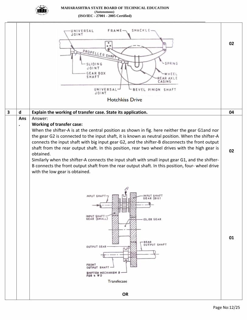
Hotchkiss Drive: It consists of leaf springs which are supported by the shackle on the frame. The front end of the spring is fixed rigidly on the frame, while rear end is supported in a shackle. The axle is attached to the spring with the help of a U-bolt. The propeller shaft is provided with two universal joints and also a sliding joint. Hollow open type propeller shaft is used.
02
MAHARASHTRA STATE BOARD OF TECHNICAL EDUCATION (Autonomous) (ISO/IEC - 27001 - 2005 Certified) __________________________________________________________________________________________________
Page No:12/25
02
3 d Explain the working of transfer case. State its application. 04 Ans
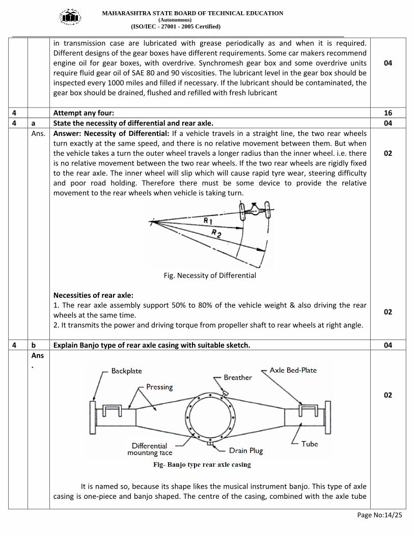
. Answer: Working of transfer case: When the shifter-A is at the central position as shown in fig. here neither the gear G1and nor the gear G2 is connected to the input shaft, it is known as neutral position. When the shifter-A connects the input shaft with big input gear G2, and the shifter-B disconnects the front output shaft from the rear output shaft. In this position, rear two wheel drives with the high gear is obtained. Similarly when the shifter-A connects the input shaft with small input gear G1, and the shifter-B connects the front output shaft from the rear output shaft. In this position, four- wheel drive with the low gear is obtained.
OR
02
01

MAHARASHTRA STATE BOARD OF TECHNICAL EDUCATION (Autonomous) (ISO/IEC - 27001 - 2005 Certified) __________________________________________________________________________________________________
Page No:13/25
Application of Transfer case: Transfer case is used in four wheel drive vehicle along with main gearbox to transmit torque and power to the rear axle.
01
3 e Why constant mesh gear box requires double de-clutching? Explain. 04 Ans
. Answer: In constant mesh gearbox the driver has to disengage the clutch twice while shifting to the required gear, hence it is called as double declutching. Double de-clutching ensures smooth engagement and disengagement with reduced wear of dogteeth, less noise and vibrations In constant mesh gear box, for smooth engagement of dog clutches it is necessary that the speed of main shaft and sliding dog clutch must be equal. To obtain lower gear, the speeds of the clutch shaft, lay shaft and main shaft must be increased. This is done by double declutching. The clutch is disengaged and the gear is brought to neutral. Then the clutch is engaged and accelerator pedal pressed to increase the speed of the main shaft gears. After this the clutch is again disengaged and the gear moved to the required lower gear and the clutch is again engaged. For changing to higher gear, however reveres effect is desired i.e., the driver has to wait the gear in neutral till the main shaft speed is decreased sufficiently for smooth engagement of the gear.
04
3 f How the lubrication of gearbox is done? 04 Ans
. Answer: Lubrication of gear box- Proper lubrication of gear box is extremely important. The transmission gears operate in a bath of lubricating oil to prevent metal-to-metal contact. Lubrication of gear box is done by putting oil of specification given by the manufacturer (the gear oil is thicker than the engine oil), in the gear box to ensure that at least one gear dips in the oil. With the clutch engaged the gears will rotate and splash the oil. The bearings located
MAHARASHTRA STATE BOARD OF TECHNICAL EDUCATION (Autonomous) (ISO/IEC - 27001 - 2005 Certified) __________________________________________________________________________________________________
Page No:14/25
in transmission case are lubricated with grease periodically as and when it is required. Different designs of the gear boxes have different requirements. Some car makers recommend engine oil for gear boxes, with overdrive. Synchromesh gear box and some overdrive units require fluid gear oil of SAE 80 and 90 viscosities. The lubricant level in the gear box should be inspected every 1000 miles and filled if necessary. If the lubricant should be contaminated, the gear box should be drained, flushed and refilled with fresh lubricant
04
4 Attempt any four: 16 4 a State the necessity of differential and rear axle. 04 Ans. Answer: Necessity of Differential: If a vehicle travels in a straight line, the two rear wheels
turn exactly at the same speed, and there is no relative movement between them. But when the vehicle takes a turn the outer wheel travels a longer radius than the inner wheel. i.e. there is no relative movement between the two rear wheels. If the two rear wheels are rigidly fixed to the rear axle. The inner wheel will slip which will cause rapid tyre wear, steering difficulty and poor road holding. Therefore there must be some device to provide the relative movement to the rear wheels when vehicle is taking turn.
Fig. Necessity of Differential
Necessities of rear axle: 1. The rear axle assembly support 50% to 80% of the vehicle weight & also driving the rear wheels at the same time. 2. It transmits the power and driving torque from propeller shaft to rear wheels at right angle.
02
02
4 b Explain Banjo type of rear axle casing with suitable sketch. 04 Ans
.
It is named so, because its shape likes the musical instrument banjo. This type of axle casing is one-piece and banjo shaped. The centre of the casing, combined with the axle tube
02

MAHARASHTRA STATE BOARD OF TECHNICAL EDUCATION (Autonomous) (ISO/IEC - 27001 - 2005 Certified) __________________________________________________________________________________________________
Page No:15/25
on one side which looks like a banjo, hence called banjo casing. The complete differential unit is carried in a separate carrier which is bolted to the axle casing. Therefore in case of any repair, the half shafts can be taken out directly from sides and the differential assembly removed by opening bolts only. A lubricant level plug, set at a height about one third up the crown wheel, is screwed into the domed cover.
02
4 c Describe construction and working of propeller shaft with neat sketch. 04 Ans
.
Construction and Working - In an automobile, the shaft which transmits the power from the gearbox output shaft to final drive (differential) is called as a propeller shaft. The propeller shaft is normally tubular in section and of one or two-piece construction. It consists mainly of three parts : a. Shaft: - As the shaft has to withstand mainly torsional loads, it is usually made of tubular cross-section. The shaft has to be well balanced to avoid whirling at high speeds. Shaft is made of steel, aluminium or composite materials. b. Slip joint: - Depending upon the type of the drive, one slip joint may be there in shaft. This serves to adjust the length of the propeller shaft when demanded by the rear axle movement. Slip joint is formed by the internal splines on the sleeve attached to the left universal joint and external splines on the propeller shaft. c. Universal joints: Depending upon the type of the rear axle one or two universal joints is used. The universal joints account for the up and down movements of the rear axle when the vehicle is running.
02
02

MAHARASHTRA STATE BOARD OF TECHNICAL EDUCATION (Autonomous) (ISO/IEC - 27001 - 2005 Certified) __________________________________________________________________________________________________
Page No:16/25
4 d Draw a neat sketch of gear selector mechanism with gear lever on top of gear box. 04 Ans Answer:
Fig. Gear selector mechanism with gear lever on the top of gear box
OR
Fig. Gear selector mechanism with gear lever on the top of gear box
04
04
MAHARASHTRA STATE BOARD OF TECHNICAL EDUCATION (Autonomous) (ISO/IEC - 27001 - 2005 Certified) __________________________________________________________________________________________________
Page No:17/25
4 e Explain salient features of alloy wheel with neat sketch. 04 Ans
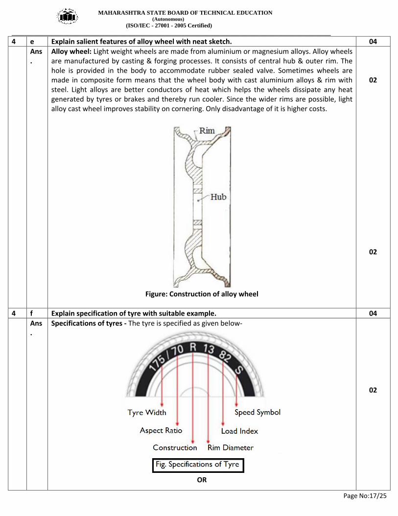
. Alloy wheel: Light weight wheels are made from aluminium or magnesium alloys. Alloy wheels are manufactured by casting & forging processes. It consists of central hub & outer rim. The hole is provided in the body to accommodate rubber sealed valve. Sometimes wheels are made in composite form means that the wheel body with cast aluminium alloys & rim with steel. Light alloys are better conductors of heat which helps the wheels dissipate any heat generated by tyres or brakes and thereby run cooler. Since the wider rims are possible, light alloy cast wheel improves stability on cornering. Only disadvantage of it is higher costs.
Figure: Construction of alloy wheel
02
02
4 f Explain specification of tyre with suitable example. 04 Ans
. Specifications of tyres - The tyre is specified as given below-
OR
02

MAHARASHTRA STATE BOARD OF TECHNICAL EDUCATION (Autonomous) (ISO/IEC - 27001 - 2005 Certified) __________________________________________________________________________________________________
Page No:18/25
(credit should be given to any suitable Example) E.g. - 175/70 R 13 82 S Where, 175 = tyre Width in mm 70 = Aspect Ratio of tyre in Percentage R = Radial 13 = Rim Diameter in inches 82 = Load Index S = Speed rating
02
5 a) Attempt any TWO 16
a) Explain with neat sketch
i) Semi Floating Rear Axle
ii) Three quarter Floating Rear Axle
08
Answer:-
i) Semi Floating Rear Axle
Fig.: Semi floating type rear axle
The figure shows a schematic diagram of the semi floating rear axle. A single ball bearing is inside the axle casing. The axle of the wheel is at the centre of the axle casing and the wheels are fitted at the end of the axle. This is done by means of key, bolt and nut. The whole weight of the vehicle is first transmitted to the suspension spring. From there it is transmitted to the axle casing from there to the axle and wheel. Finally it is transmitted to the ground. The axle can be removed by first placing a support below the axle casing.
02
02
MAHARASHTRA STATE BOARD OF TECHNICAL EDUCATION (Autonomous) (ISO/IEC - 27001 - 2005 Certified) __________________________________________________________________________________________________
Page No:19/25
ii) Three quarter Floating Rear Axle:-
Fig;- Three quarter floating
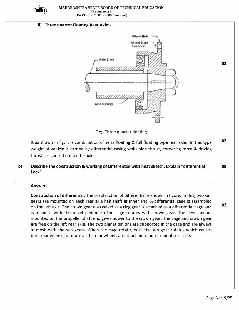
It as shown in fig. it is combination of semi floating & full floating type rear axle.. In this type weight of vehicle is carried by differential casing while side thrust, cornering force & driving thrust are carried out by the axle.
02
02
b) Describe the construction & working of Differential with neat sketch. Explain “differential Lock”
08
Answer:-
Construction of differential: The construction of differential is shown in figure. In this, two sun gears are mounted on each rear axle half shaft at inner end. A differential cage is assembled on the left axle. The crown gear also called as a ring gear is attached to a differential cage and is in mesh with the bevel pinion. So the cage rotates with crown gear. The bevel pinion mounted on the propeller shaft end gives power to the crown gear. The cage and crown gear are free on the left rear axle. The two planet pinions are supported in the cage and are always in mesh with the sun gears. When the cage rotate, both the sun gear rotates which causes both rear wheels to rotate as the rear wheels are attached to outer end of rear axle.
02

MAHARASHTRA STATE BOARD OF TECHNICAL EDUCATION (Autonomous) (ISO/IEC - 27001 - 2005 Certified) __________________________________________________________________________________________________
Page No:20/25
Fig:- Construction of differential
Working of differential: When vehicle moves in a straight line, the power comes from propeller shaft to the bevel pinion which drives the crown wheel. Then it is carried to the differential cage in which a set of planet pinions and sun gears are located. From the sun gear it is transmitted to the road wheels through axle half shafts. In this case, the crown wheel, differential cage, planet pinions and sun gears all turn as a single unit and there is no any relative motion between the sun gear and planet pinion. The planet pinions do not rotate about their own axis. Both the road wheels turn at the same speed. When vehicle takes a turn, the inner wheel experiences a resistance and tends to rotate in opposite direction. Due to this the planet pinions starts rotating about their own axis and around the sun gear and transmit more rotary motion to the other side sun gear. So that outer sun gear rotates faster than the inner sun gear. Therefore the outer road wheel runs faster than the inner road wheel and covers a more distance. Concept of Differential Lock:-If the rear wheel is lying on soft mud or loose dirt ,sand & while other is on solid ground at that time the wheel which on soft mud & having less resistance spins about its own axis due to differential action while the wheel on solid ground is not driven remains stationary in such a situation vehicle does not moves from the place if differential lock is applied to both wheels and it gives grip to the wheel which is on solid ground vehicle can easily comes out from the obstacle .differential action stop in such situation called differential lock it can be manual or automatically operated
02
02
02

MAHARASHTRA STATE BOARD OF TECHNICAL EDUCATION (Autonomous) (ISO/IEC - 27001 - 2005 Certified) __________________________________________________________________________________________________
Page No:21/25
c) i) State the function of Hooks Joint.
ii) Explain Constant velocity joint with neat sketch.
08
Answer:-
i) Hooks Joint:-
Fig:-Hooks Joint
Functions: In front engine rear wheel driven vehicles, the transmission rigidly fixed to the frame or body, is normally at higher level than wheels. The rear axle is suspended to the frame through springs. The driveshaft hence requires some flexibility at the bend near the transmission and at the axle. So the universal joints are used at front and rear end of propeller shaft which transmit the power to the wheels even if the heights of transmission and rear axle are different. Also whenever the axle moves up and down due to road irregularities, the angle of drive changes continuously and universal joint allows transmission of power and rotary motion at a varied angle.
Constant Velocity Joint:-
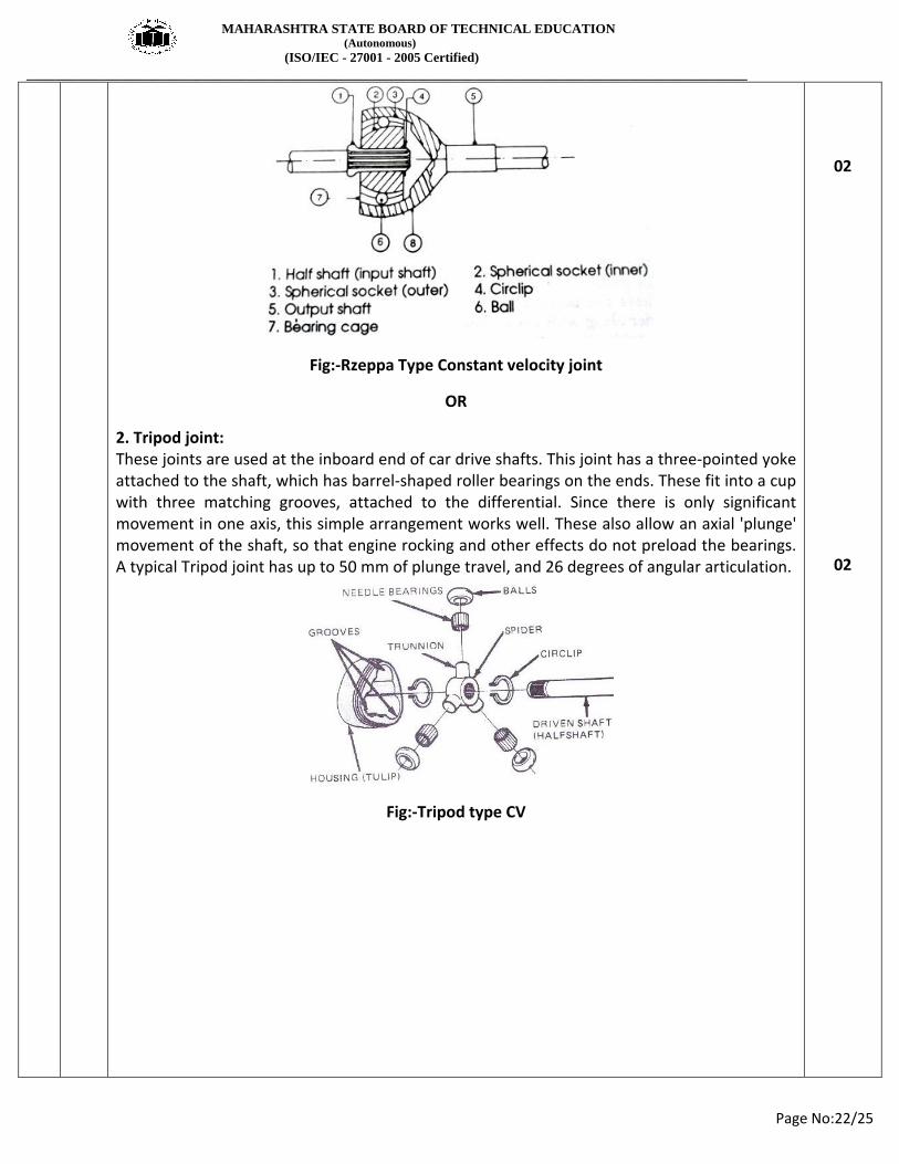
CV joints are sliding or plunging joints. They move in and out to change effective length of the half shafts. There are two types of CV joints, 1. Rzeppa or double offset CV joint 2. Tripod CV joint. 1. Rzeppa joint (2Marks foe Description & 2 Marks for Figure) A Rzeppa joint consist of a spherical inner with 6 grooves in it, and a similar enveloping outer shell. Each groove guides one ball. The input shaft fits in the center of a large, steel, star-shaped "gear" that nest inside a circular cage. The cage is spherical but with ends open, and it typically has six openings around the perimeter. This cage and gear fit into a grooved cup that has a splined and threaded shaft attached to it. Six large steel balls sit inside the cup grooves and fit into the cage openings, nestled in the grooves of the star gear.
02
02
02
02
MAHARASHTRA STATE BOARD OF TECHNICAL EDUCATION (Autonomous) (ISO/IEC - 27001 - 2005 Certified) __________________________________________________________________________________________________
Page No:22/25
Fig:-Rzeppa Type Constant velocity joint
OR
2. Tripod joint: These joints are used at the inboard end of car drive shafts. This joint has a three-pointed yoke attached to the shaft, which has barrel-shaped roller bearings on the ends. These fit into a cup with three matching grooves, attached to the differential. Since there is only significant movement in one axis, this simple arrangement works well. These also allow an axial 'plunge' movement of the shaft, so that engine rocking and other effects do not preload the bearings. A typical Tripod joint has up to 50 mm of plunge travel, and 26 degrees of angular articulation.
Fig:-Tripod type CV
02
02

MAHARASHTRA STATE BOARD OF TECHNICAL EDUCATION (Autonomous) (ISO/IEC - 27001 - 2005 Certified) __________________________________________________________________________________________________
Page No:23/25
6) Attempt Any Two 16
a) i) Draw any four section of chassis frame with their merits.
ii) Draw neat labelled layout of front-Engine Rear Wheel Drive Vehicle
08
Answer:-
i) any four section of chassis frame with their merits:-
Figure: Frame sections Channel Section: The channel section is used for making the long members of the frame. It provides a good resistance to bending. It is poor in torsion. This type of section is used in conventional ladder like frames of LMV (e.g. Mahindra Jeep) and HMV (e.g. Truck, Bus etc). Box section: Box section is good for both bending and torsion. The cross member of conventional frame are made of box sections. This type of frame section is used in frames of motorcycles (e.g. Bajaj Pulsar, Boxer etc.) Tubular sections: Tubular sections provide good resistance to torsion but poor resistance to bending. Now a days, tubular section is used to make complete chassis frame of three wheeler, scooter, motorcycle, matador and pickup van etc I-Section: I- section is used for making cross members. I-Section has high moment of inertia and stiffness which makes it resistant to bending moments. The web provides resistance against shear forces. These sections are not resistant to torsional loading (twisting) and they shall not used in the cases where torsion is dominant.
02
02

MAHARASHTRA STATE BOARD OF TECHNICAL EDUCATION (Autonomous) (ISO/IEC - 27001 - 2005 Certified) __________________________________________________________________________________________________
Page No:24/25
ii)Layout of Front Engine Rear Wheel Drive Vehicle:
04
b) i) State the effects of inflation on life of tyre
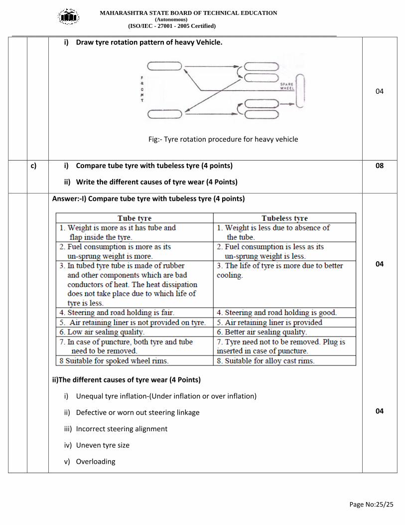
ii) Draw tyre rotation pattern of heavy Vehicle.
08
Answer:-
i) State the effects of inflation on life of tyre:-
The inflation pressures are recommended by the vehicle manufacturer depending upon tyre size, speed and load. Although tires are made up of more or less airtight materials, they still allow minute quantities of air to gradually leak away over time. Therefore, the tire inflation pressure must be checked regularly and adjusted as necessary whenever it differs from the specified pressure. Effects of Under-inflation: (02 Marks) 1) Uneven tread wear, more wear at tyre sides. 2) Lack of directional stability. 3) Increased rolling resistance leading to increased fuel consumption. 4) Excessive flexing of sidewall causes build up. 5) Vehicle will roll on curves. Effects of Over-inflation: (02 Marks) 1) Reduced tread contact area with road surface. 2) Reduced tyre grip. 3) Increased vibration resulting in uncomfortable ride. 4) Increased stresses may causes tread separation and crack in the side wall.
02
02
MAHARASHTRA STATE BOARD OF TECHNICAL EDUCATION (Autonomous) (ISO/IEC - 27001 - 2005 Certified) __________________________________________________________________________________________________
Page No:25/25
i) Draw tyre rotation pattern of heavy Vehicle.
Fig:- Tyre rotation procedure for heavy vehicle
04
c) i) Compare tube tyre with tubeless tyre (4 points)
ii) Write the different causes of tyre wear (4 Points)
08
Answer:-I) Compare tube tyre with tubeless tyre (4 points)
ii)The different causes of tyre wear (4 Points)
i) Unequal tyre inflation-(Under inflation or over inflation)
ii) Defective or worn out steering linkage
iii) Incorrect steering alignment
iv) Uneven tyre size
v) Overloading
04
04