17 examination 17526 - msbte model answer...
TRANSCRIPT

MAHARASHTRA STATE BOARD OF TECHNICAL EDUCATION (Autonomous) (ISO/IEC - 27001 - 2005 Certified)
MODEL ANSWER Summer – 17 EXAMINATION
Subject Title: Automobile Engineering Subject Code:
Page 1 of 26
17526
.3Important Instructions to examiners: 1) The answers should be examined by key words and not as word-to-word as given in the model answer scheme. 2) The model answer and the answer written by candidate may vary but the examiner may try to assess the understanding level of the candidate. 3) The language errors such as grammatical, spelling errors should not be given more importance. (Not applicable for subject English and Communication Skills). 4) While assessing figures, examiner may give credit for principal components indicated in the figure. The figures drawn by candidate and model answer may vary. The examiner may give credit for any equivalent figure drawn. 5) Credits may be given step wise for numerical problems. In some cases, the assumed constant values may vary and there may be some difference in the candidate’s answers and model answer. 6) In case of some questions credit may be given by judgment on part of examiner of relevant answer based on candidate’s understanding. 7) For programming language papers, credit may be given to any other program based on equivalent concept. ………………………………………………………………………………………………………………………….
Q. No
Sub Q. N.
Answer Marking Scheme
1 (A) Attempt any THREE of the following 12
(i) Write any four advantages of front engine rear wheel drive. 4
Answer: ( 1 mark for each, any four) (Due credit can be given for suitable
reply).
1. Even weight distribution - The division of weight between the front and rear wheels has a significant impact on a car's handling, and it is much easier to get a 50/50 weight distribution in a rear wheel drive car than in a front wheel drive car, as more of the engine can lie between the front and rear wheels (in the case of a mid engine layout, the entire engine), and the transmission is moved much farther back.
2. Steering radius - As no complicated drive shaft joints are required at the front wheels, it is possible to turn them further than would be possible using front wheel drive, resulting in a smaller steering radius.
3. More predictable steering in low traction conditions (i.e.: ice or gravel) because the steering wheels maintain traction and the ability to affect the motion of the vehicle even if the drive wheels are slipping.
4. Simple front axle design with steering mechanism. 5. Better engine cooling by taking full benefits of natural air stream flowing
across the radiator. 6. Accessibility to various engine components is easier. 7. Less costly and easier maintenance - Rear wheel drive is mechanically simpler
and typically does not involve packing as many parts into as small a space as does front wheel drive, thus requiring less disassembly or specialized tools in order to
1 mark for
each, any four
MAHARASHTRA STATE BOARD OF TECHNICAL EDUCATION (Autonomous) (ISO/IEC - 27001 - 2005 Certified)
MODEL ANSWER Summer – 17 EXAMINATION
Subject Title: Automobile Engineering Subject Code:
Page 2 of 26
17526
replace parts. 8. Weight transfer during acceleration. (During heavy acceleration, the front end
rises, and more weight is placed on the rear, or driving wheels). 9. Better handling in dry conditions - accelerating force is applied to the rear wheels,
on which the down force increases, due to load transfer in acceleration, making the rear tires better able to take simultaneous acceleration and curving than the front tires.
10.Towing - Rear wheel drive puts the wheels which are pulling the load closer to the point where a trailer articulates, helping steering, especially for large loads.
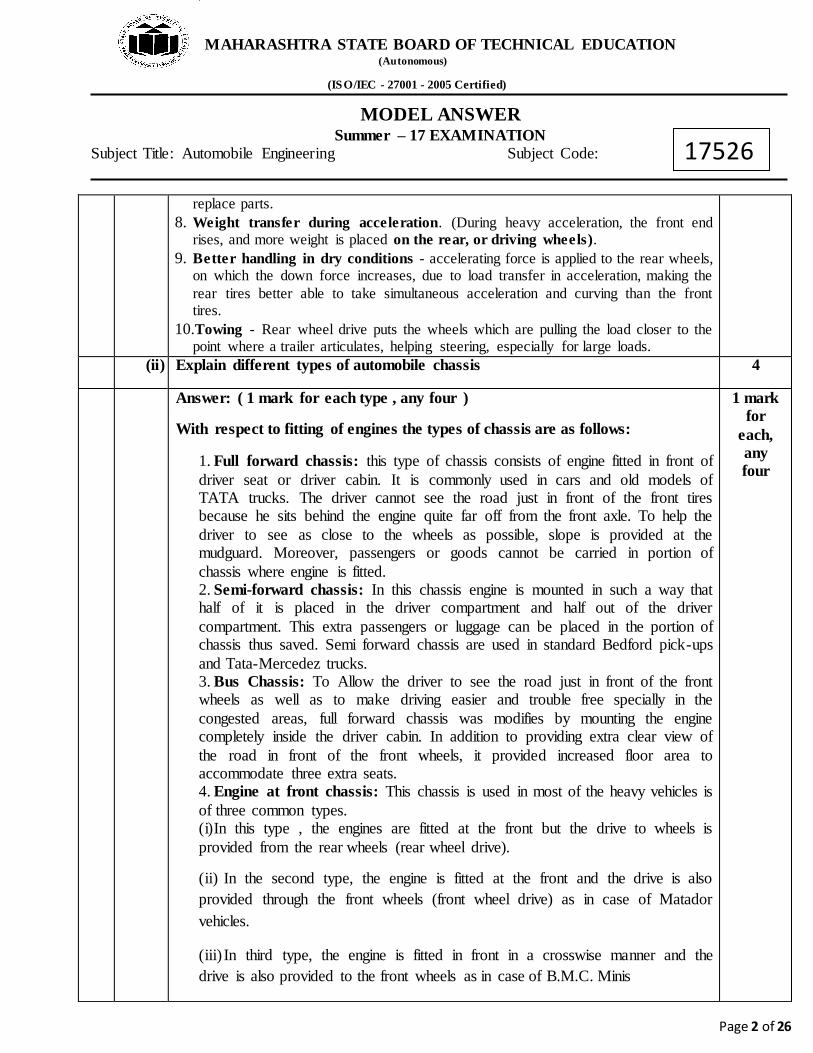
(ii) Explain different types of automobile chassis 4
Answer: ( 1 mark for each type , any four )
With respect to fitting of engines the types of chassis are as follows:
1. Full forward chassis: this type of chassis consists of engine fitted in front of driver seat or driver cabin. It is commonly used in cars and old models of TATA trucks. The driver cannot see the road just in front of the front tires because he sits behind the engine quite far off from the front axle. To help the driver to see as close to the wheels as possible, slope is provided at the mudguard. Moreover, passengers or goods cannot be carried in portion of chassis where engine is fitted. 2. Semi-forward chassis: In this chassis engine is mounted in such a way that half of it is placed in the driver compartment and half out of the driver compartment. This extra passengers or luggage can be placed in the portion of chassis thus saved. Semi forward chassis are used in standard Bedford pick-ups and Tata-Mercedez trucks. 3. Bus Chassis: To Allow the driver to see the road just in front of the front wheels as well as to make driving easier and trouble free specially in the congested areas, full forward chassis was modifies by mounting the engine completely inside the driver cabin. In addition to providing extra clear view of the road in front of the front wheels, it provided increased floor area to accommodate three extra seats. 4. Engine at front chassis: This chassis is used in most of the heavy vehicles is of three common types. (i)In this type , the engines are fitted at the front but the drive to wheels is provided from the rear wheels (rear wheel drive).
(ii) In the second type, the engine is fitted at the front and the drive is also provided through the front wheels (front wheel drive) as in case of Matador vehicles.
(iii) In third type, the engine is fitted in front in a crosswise manner and the drive is also provided to the front wheels as in case of B.M.C. Minis
1 mark for
each, any four
MAHARASHTRA STATE BOARD OF TECHNICAL EDUCATION (Autonomous) (ISO/IEC - 27001 - 2005 Certified)
MODEL ANSWER Summer – 17 EXAMINATION
Subject Title: Automobile Engineering Subject Code:
Page 3 of 26
17526
5) Engine fitted at the rear: In this chassis, engine is fitted at the rear of the vehicle thus saving a lot of space at the front eliminating long propeller shafts and providing a clear view of the road at the front. This system is used in popular vehicles like Renault, Daulphine and Volkswagen. Engine is also mounted at the rear end of the chassis in imported Leyland Double Decker Buses. In this chassis fix up of controls like gear shift lever, oil and fuel gauge, accelerated linkage is very complicated. Moreover natural draft of air to radiator due to forward motion of vehicle is also missing.
6) Engine fitted in centrechassis : In this chassis engine is fitted in centre its centre under the chassis to remove defects of engine fitted at the rear chassis and to use the complete floor of the space. This chassis was used in Royal Tiger Wordmaster busses previous plied in Delhi by Delhi Transport Undertaking.
7) Long wheel base chassis : Standard truck chassis are used for making trucks and to permit the truck to carry the exact weight for which they are designed, load is piled up. But in case of bus chassis, seats are fixed and distance between each seat is fixed as per Motor Vehicle Rules, therefore the vehicle will be running with less weight as less number of passengers can travel in it. To accommodate more passengers and to carry more weight, bus chassis are provide with longer wheel base(i.e. center distance of front and rear wheels) resulting in longer chassis.
8) Overhang Chassis: In order to increase the floor space to accommodate more goods and passengers , certain length of the chassis is extended after rear axle(rear overhang) and after the front axle (front overhang).
9) Half- integral and Half-frame chassis: It is an improved form of chassis used in fiat of Padmani cars. In this chassis half frame bolted to the floor of vehicle is fixed at the front end, where the engine gear box and front suspension is fixed. The rear portion of the floor functions as frame for the vehicle body.
(iii) State the advantages of LPG and CNG operated engines. 4
Answer: ( 1 Mark for each ) Advantages of LPG & CNG operated engines: 1. Low cost of fuel. 2. Less pollution and more efficiency. 3. It is safer for vehicle. The LPG/CNG fuel tank is made of thick wall so they can withstand dynamic explosion, crash test, and direct gunfire. 4. Increased life of lubricating oils, as LPG/CNG does not contaminate and dilute the crankcase oil. No need of oil change frequently which reduce

MAHARASHTRA STATE BOARD OF TECHNICAL EDUCATION (Autonomous) (ISO/IEC - 27001 - 2005 Certified)
MODEL ANSWER Summer – 17 EXAMINATION
Subject Title: Automobile Engineering Subject Code:
Page 4 of 26
17526
vehicle maintenance. 5. Due to its antilock property, CNG can be used safely in engine with compression ratio as high as 12:1 compare to gasoline engine. Because CNG has a higher octane number than petrol, CNG engines operate at higher compression ratio without knocking. 6. CNG/LPG fuel systems are sealed, preventing fuel losses from spills or evaporation.
(iv) Draw general layout of front engine front wheel drive car 4
Answer:(Sketch - 4 Marks)
Fig. Front Engine Front Wheel Drive
(B) Attempt any ONE of the following : 6
(i) State and explain different forces acting on the vehicle body related to aerodynamics.
6
Answer:(2 marks for each force) (suitable credit may be given to suitable explanation) Forces and moments acting on vehicle body : As a result of air stream interacting with the vehicle, the following forces and moments are imposed on vehicle. Direction Forces Moments Longitudinal direction (x- axis, Positive rearward)
Drag Rolling moment
Lateral Direction (y- axis, positive rightward)
Side force Pitching moment
Vertical ( Z- axis , Positive upward) Lift Yawing moment
2 marks for each
force

MAHARASHTRA STATE BOARD OF TECHNICAL EDUCATION (Autonomous) (ISO/IEC - 27001 - 2005 Certified)
MODEL ANSWER Summer – 17 EXAMINATION
Subject Title: Automobile Engineering Subject Code:
Page 5 of 26
17526
Drag: It is the largest and most important aerodynamic force encountered by vehicle at normal highway speeds. Air drag is given by the equation, DA = ½ ρ V2 CD A ρ= Density of air V= Speed of Vehicle CD = Coefficient of Drag A= Frontal Area of vehicle. The major factors included in aerodynamic drag are-Induced drag, profile drag, Friction drag
Figure Aerodynamic Drag
Side Force: Lateral wind component also impose the side force on the vehicle attempting to change the direction of travel. The exact effect depends on the vehicle and nature of cross wind. The equation for side force is given by SA = ½ ρ V2 Cs A ρ= Density of air V= Total wind velocity Cs = Side force Coefficient A= Frontal Area of vehicle. Lift force: The pressure difference fro top to bottom of vehicle causes the lift force. The list force is measured at the centerline of vehicle at the center of wheel base. The lift force given by equation, LA = ½ ρ V2 CL A ρ= Density of air V= Total wind velocity CL = Lift Coefficient A= Frontal Area of vehicle.

MAHARASHTRA STATE BOARD OF TECHNICAL EDUCATION (Autonomous) (ISO/IEC - 27001 - 2005 Certified)
MODEL ANSWER Summer – 17 EXAMINATION
Subject Title: Automobile Engineering Subject Code:
Page 6 of 26
17526
Figure aerodynamic lift
Pitching moment: The moment of vehicle along x-axis due to forces in Z-direction is called as pitching moment Yawing Moment: Lateral force caused by side wind does not normally act at the mid wheel base position, thus the yawing moment is produced. Rolling moment: The lateral force caused by a side wind acts at the elevated point on the vehicle, thus the rolling moment is produced. The moment has only a minor effect on stability of vehicle.
Fig Pitching, yawing & rolling moments
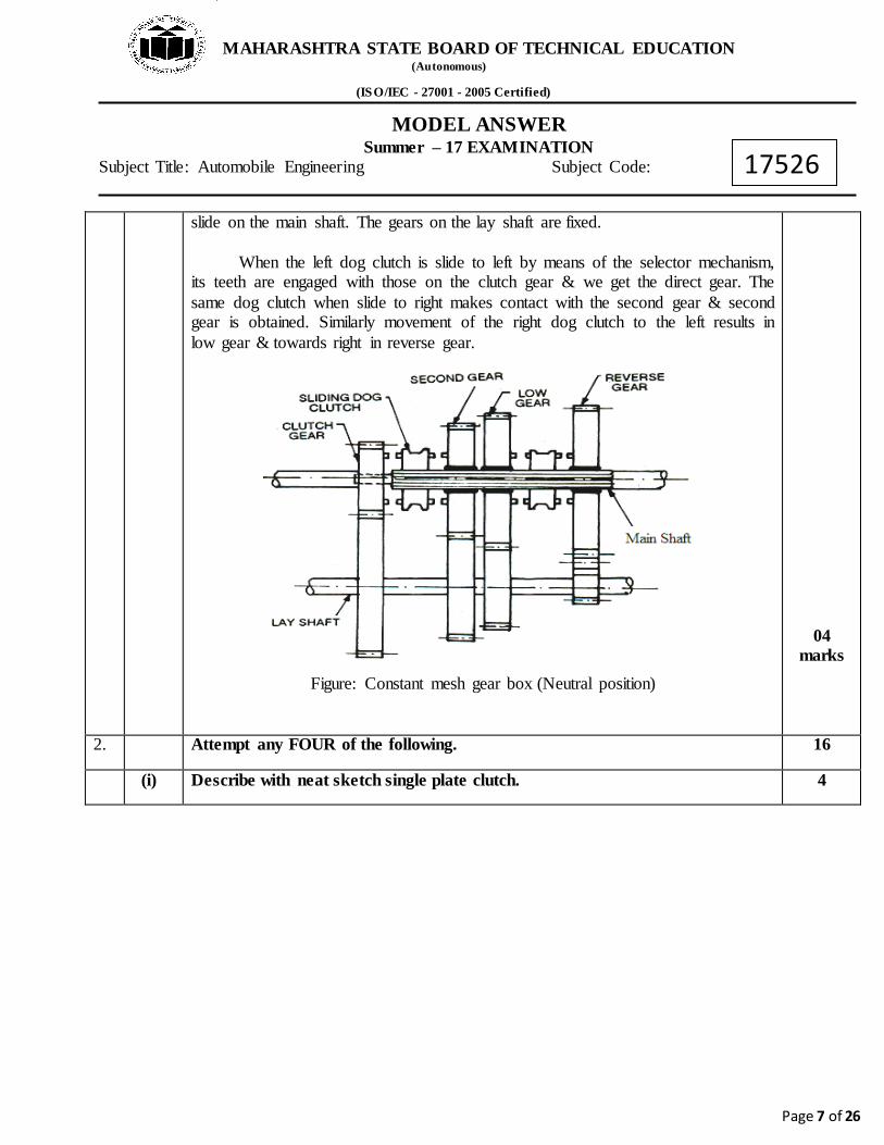
(ii) Explain with neat sketch working of constant mesh gear box. 6
Answer: (Working 2 marks, Sketch-4 marks) Working of constant mesh gear box: In this type of gear box, all the gears are in constant mesh with the corresponding gears on the lay shaft. The gears on the main shaft which is splined are free. The dog clutches are provided which are free to
02 marks
MAHARASHTRA STATE BOARD OF TECHNICAL EDUCATION (Autonomous) (ISO/IEC - 27001 - 2005 Certified)
MODEL ANSWER Summer – 17 EXAMINATION
Subject Title: Automobile Engineering Subject Code:
Page 7 of 26
17526
slide on the main shaft. The gears on the lay shaft are fixed. When the left dog clutch is slide to left by means of the selector mechanism, its teeth are engaged with those on the clutch gear & we get the direct gear. The same dog clutch when slide to right makes contact with the second gear & second gear is obtained. Similarly movement of the right dog clutch to the left results in low gear & towards right in reverse gear.
Figure: Constant mesh gear box (Neutral position)
04 marks
2. Attempt any FOUR of the following. 16
(i) Describe with neat sketch single plate clutch. 4

MAHARASHTRA STATE BOARD OF TECHNICAL EDUCATION (Autonomous) (ISO/IEC - 27001 - 2005 Certified)
MODEL ANSWER Summer – 17 EXAMINATION
Subject Title: Automobile Engineering Subject Code:
Page 8 of 26
17526
Answer: (Description- 2 marks, Sketch-2 marks)
A single disc or plate clutch as shown in figure, consist of a clutch plate whose both sides are faced with the friction material (usually ferrodo). It is mounted on the hub which is free to move axially along the splines of the driven shaft. The pressure plate is mounted inside the clutch body which is bolted to the flywheel. Both the pressure plate and the flywheel rotate with the engine crankshaft or the driving shaft. The pressure plate pushes the clutch plate towards the flywheel by a set of strong spring which are arranged radially inside the body. The three levers (also known as release levers or fingers) are carried on the pivots suspended from the case of the body. These are arranged in such a manner so that the pressure plate moves away from flywheel by the inward movement of a thrust bearing. The bearing is mounted upon the forked shaft and moves forward when the clutch pedal is pressed.
Disengaging the clutch:
When clutch pedal is pressed down, it’s linkage forces the thrust bearing to move towards the flywheels and pressing the pressure plate away from the flywheel thereby the compression springs are compressed. This action removes the pressure from the clutch plate and the driving shaft comes to stationary position.
Engaging the clutch:
On the other hand when the foot is taken off from the clutch pedal, the thrust bearing moves back by levers this action allows the springs to extend and thus the pressure plate pushes the clutch plate back towards the flywheel. The cluch is engaged and power is transmitted from engine to gear box.
Figure Single Plate Clutch
02 marks
02 marks

MAHARASHTRA STATE BOARD OF TECHNICAL EDUCATION (Autonomous) (ISO/IEC - 27001 - 2005 Certified)
MODEL ANSWER Summer – 17 EXAMINATION
Subject Title: Automobile Engineering Subject Code:
Page 9 of 26
17526
(ii) State function of universal and slip joint used in propeller shaft. 04
Answer: ( Universal joint – 2 marks , Slip joint - 2 Marks) Function of Universal Joint- Universal joint allows transmission of power and rotary motion at an angle which varies as a vehicle encounters a bump. Function of Slip Joint- This joint allows variation in length of the propeller shaft when vehicle came across road irregularities.
02 marks
02 marks
(iii) Why differential is used in automobile? Explain working of differential 04
Answer: - ( Need- 2 Marks, Working- 2 marks) Need of Differential in automobile: 1) When vehicle is taking turn outer wheel will have to travel greater distance as compared to inner wheel. 2). If the vehicle has a solid rear axle only and no other device, there will be tendency to skid. 3. Hence wheel skidding is avoided by incorporating the mechanism i.e. differential. 4) Differential reduces the speed of inner wheel and increases the speed of outer wheel when vehicle is taking turn, at the same time keep the speed of rear wheel same when going straight ahead. Working of Differential :-
02 marks

MAHARASHTRA STATE BOARD OF TECHNICAL EDUCATION (Autonomous) (ISO/IEC - 27001 - 2005 Certified)
MODEL ANSWER Summer – 17 EXAMINATION
Subject Title: Automobile Engineering Subject Code:
Page 10 of 26
17526
1. When vehicle moves in a straight line: The power comes from propeller shaft to the bevel pinion which drives the crown wheel. Then it is carried to the differential cage in which a set of planet pinions and sun gears are located. From the sun gear it is transmitted to the road wheels through axle half shafts. In this case, the crown wheel, differential cage, planet pinions and sun gears all turn as a single unit and there is no any relative motion between the sun gear and planet pinion. The planet pinions do not rotate about their own axis. The road wheels, half shafts and sun wheels offer the same resistance to being turned and the differential gearing does not therefore operate. Both the road wheels turn at the same speed. 2. When Vehicle takes a turn: The inner wheel experiences a resistance and tends to rotate in opposite direction. Due to this the planet pinions starts rotating about their own axis and around the sun gear and transmit more rotary motion to the outer side sun gear. So that outer sun gear rotates faster than the inner sun gear. Therefore the outer road wheel runs faster than the inner road wheel and covers a more distance to negotiate a turn safely.
02 marks
(iv) State different types of rear axle. Explain working of any one. 04
Answer: (types- 1 marks, Explanation & sketch- 3marks) Types of Rear Axle:
1) Semi floating Rear Axle 2) Quarter Floating rear axle 3) Fully floating rear axle
Semi floating Rear Axle
01 mark
03 marks for any one type.

MAHARASHTRA STATE BOARD OF TECHNICAL EDUCATION (Autonomous) (ISO/IEC - 27001 - 2005 Certified)
MODEL ANSWER Summer – 17 EXAMINATION
Subject Title: Automobile Engineering Subject Code:
Page 11 of 26
17526
Figure Semi floating Rear Axle The figure shows a schematic diagram of the semi floating rear axle. A single ball bearing is inside the axle casing. The axle of the wheel is at the centre of the axle casing and the wheels are fitted at the end of the axle. This is done by means of key, bolt and nut. The whole weight of the vehicle is first transmitted to the suspension spring. From there it is transmitted to the axle casing from there to the axle and wheel. Finally it is transmitted to the ground. The axle can be removed by first placing a support below the axle casing.
OR Three quarter floating rear axle :
Figure Three quarter floating rear axle
This axle is generally used on large vehicles and high performance cars. In this axle, a bearing is provided inside the axle housing to carry the final drive unit. To support the weight of the vehicle, an outer bearing is also placed between the wheel hub and the axle housing. The weight of the vehicle is transferred to the axle casing while the side trust and the driving torques are supported on the axle shaft. One bearing of the brake drum is fitted on the axle while the other on the axle tube. The hub bearing housing flange carries the wheel studs. It is either integral with the half shaft or carried on a keyed taper pass through the half shaft flange. During cornering, the half shafts are only subjected to a bending load. As shown in the figure , this axle is quite complicated but more reliable as compared to semi-floating axle. The wheel will still be attached to car on case of half shaft failure. But the side loads may cause it to rock on the bearing.
OR Full Floating Rear Axle:

MAHARASHTRA STATE BOARD OF TECHNICAL EDUCATION (Autonomous) (ISO/IEC - 27001 - 2005 Certified)
MODEL ANSWER Summer – 17 EXAMINATION
Subject Title: Automobile Engineering Subject Code:
Page 12 of 26
17526
- In this type of axle two taper roller bearings are used. Bearings are placed
between the axle housing and the wheel hub. Since the load of the vehicle is supported completely by the axle housing.
- The axle only transmits driving torque. The inner end is supported inside gear of differential and outer end have a flange to which wheel hub is bolted.
- The axle may be removed or replace from the housing without disturbing the wheel by removing the nut. This type of axle is more expensive and heavier than other axle. This type is used in trucks or commercial vehicles.
(v) What are the requirements of steering systems? 04
Answer: (1 mark for each, any four) Requirements of Steering system:
1. It should be very accurate and easy to handle. 2. It should provide directional stability. 3. It should multiply the turning effort applied on the steering wheel by the
driver. 4. It should be irreversible to certain degree so that the shocks of road surface
encountered by the wheels are not transmitted to the driver’s hand. 5. The mechanism should have self –righting effect so that when the driver
releases the steering wheel after negotiating the turn the wheel should try to achieve straight ahead position.
01 marks
for each, any four
Q.3
(A) Attempt any TWO of the following.
16
(a) With neat sketch write construction and working of rack and pinion type steering system
08
Answer: Diagram 4 Marks Construction 2 Marks Working 2 Marks
MAHARASHTRA STATE BOARD OF TECHNICAL EDUCATION (Autonomous) (ISO/IEC - 27001 - 2005 Certified)
MODEL ANSWER Summer – 17 EXAMINATION
Subject Title: Automobile Engineering Subject Code:
Page 13 of 26
17526
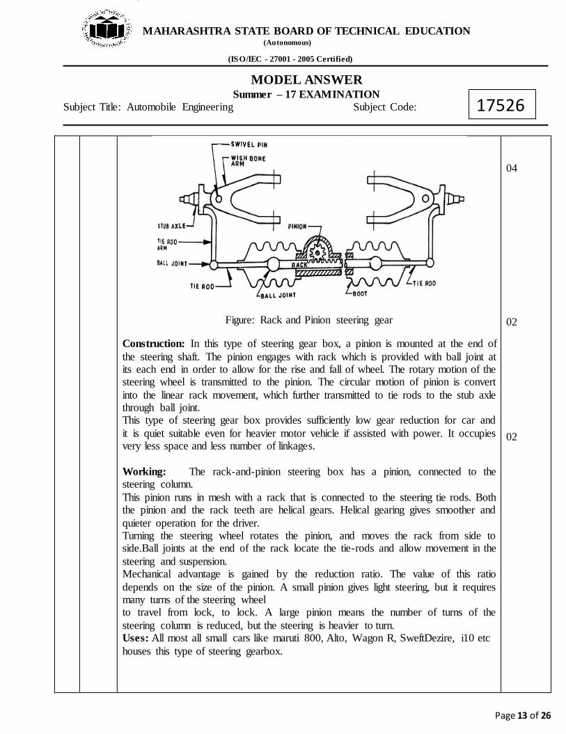
Figure: Rack and Pinion steering gear
Construction: In this type of steering gear box, a pinion is mounted at the end of the steering shaft. The pinion engages with rack which is provided with ball joint at its each end in order to allow for the rise and fall of wheel. The rotary motion of the steering wheel is transmitted to the pinion. The circular motion of pinion is convert into the linear rack movement, which further transmitted to tie rods to the stub axle through ball joint. This type of steering gear box provides sufficiently low gear reduction for car and it is quiet suitable even for heavier motor vehicle if assisted with power. It occupies very less space and less number of linkages. Working: The rack-and-pinion steering box has a pinion, connected to the steering column. This pinion runs in mesh with a rack that is connected to the steering tie rods. Both the pinion and the rack teeth are helical gears. Helical gearing gives smoother and quieter operation for the driver. Turning the steering wheel rotates the pinion, and moves the rack from side to side.Ball joints at the end of the rack locate the tie-rods and allow movement in the steering and suspension. Mechanical advantage is gained by the reduction ratio. The value of this ratio depends on the size of the pinion. A small pinion gives light steering, but it requires many turns of the steering wheel to travel from lock, to lock. A large pinion means the number of turns of the steering column is reduced, but the steering is heavier to turn. Uses: All most all small cars like maruti 800, Alto, Wagon R, SweftDezire, i10 etc houses this type of steering gearbox.
04 02 02
MAHARASHTRA STATE BOARD OF TECHNICAL EDUCATION (Autonomous) (ISO/IEC - 27001 - 2005 Certified)
MODEL ANSWER Summer – 17 EXAMINATION
Subject Title: Automobile Engineering Subject Code:
Page 14 of 26
17526
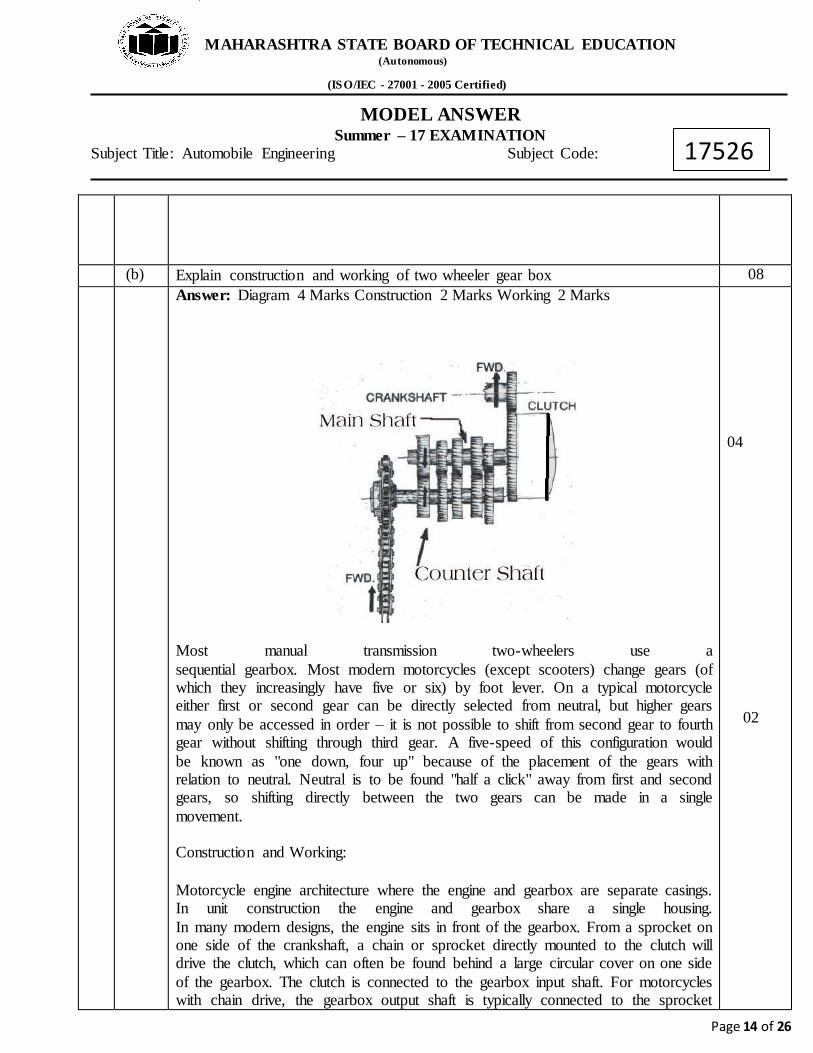
(b) Explain construction and working of two wheeler gear box 08 Answer: Diagram 4 Marks Construction 2 Marks Working 2 Marks
Most manual transmission two-wheelers use a sequential gearbox. Most modern motorcycles (except scooters) change gears (of which they increasingly have five or six) by foot lever. On a typical motorcycle either first or second gear can be directly selected from neutral, but higher gears may only be accessed in order – it is not possible to shift from second gear to fourth gear without shifting through third gear. A five-speed of this configuration would be known as "one down, four up" because of the placement of the gears with relation to neutral. Neutral is to be found "half a click" away from first and second gears, so shifting directly between the two gears can be made in a single movement.
Construction and Working:
Motorcycle engine architecture where the engine and gearbox are separate casings. In unit construction the engine and gearbox share a single housing. In many modern designs, the engine sits in front of the gearbox. From a sprocket on one side of the crankshaft, a chain or sprocket directly mounted to the clutch will drive the clutch, which can often be found behind a large circular cover on one side of the gearbox. The clutch is connected to the gearbox input shaft. For motorcycles with chain drive, the gearbox output shaft is typically connected to the sprocket
04 02
MAHARASHTRA STATE BOARD OF TECHNICAL EDUCATION (Autonomous) (ISO/IEC - 27001 - 2005 Certified)
MODEL ANSWER Summer – 17 EXAMINATION
Subject Title: Automobile Engineering Subject Code:
Page 15 of 26
17526
which drives the final drive chain. Most manual motorcycle gearboxes have "constant mesh" gears which are always mated but may rotate freely on a shaft until locked by a toothed sliding collar or "dog clutch ". Since the gears are always rotating and can only be accessed sequentially, synchromesh is not generally needed. To save space, both shafts may contain a mixture of fixed and free-spinning gears, with some gears built into the sliding parts.
02
(c) Give any four probable causes of tyre wear and give its remedies 08
Answer: ( Any four causes with remedies ) Causes of tyre wear and remedies:- (02 marks each) 1) Incorrect inflation –ensure correct tyre pressure. 2) Excessive braking and violent acceleration ---avoid rash driving 3) Worn king pins--------replace it. 4) Misalignment ------ensure wheel alignment. 5) Wrong loading ----- ensure proper loading 6) Toe-out incorrect on turn----- ensure wheel alignment 7) Careless driving --- ensure proper driving 8) Incorrect caster ,camber or toe in ------ensure wheel alignm 9) Damaged beads--- ensure proper driving 10) Bleeding of air in tyre---------ensure valve 11) Out of balance wheel-------- ensure wheel alignment
02 mark each
4 (A) Attempt any THREE of the following: 12
(i) Define and give range of angles (1) Castor (2) Camber
04
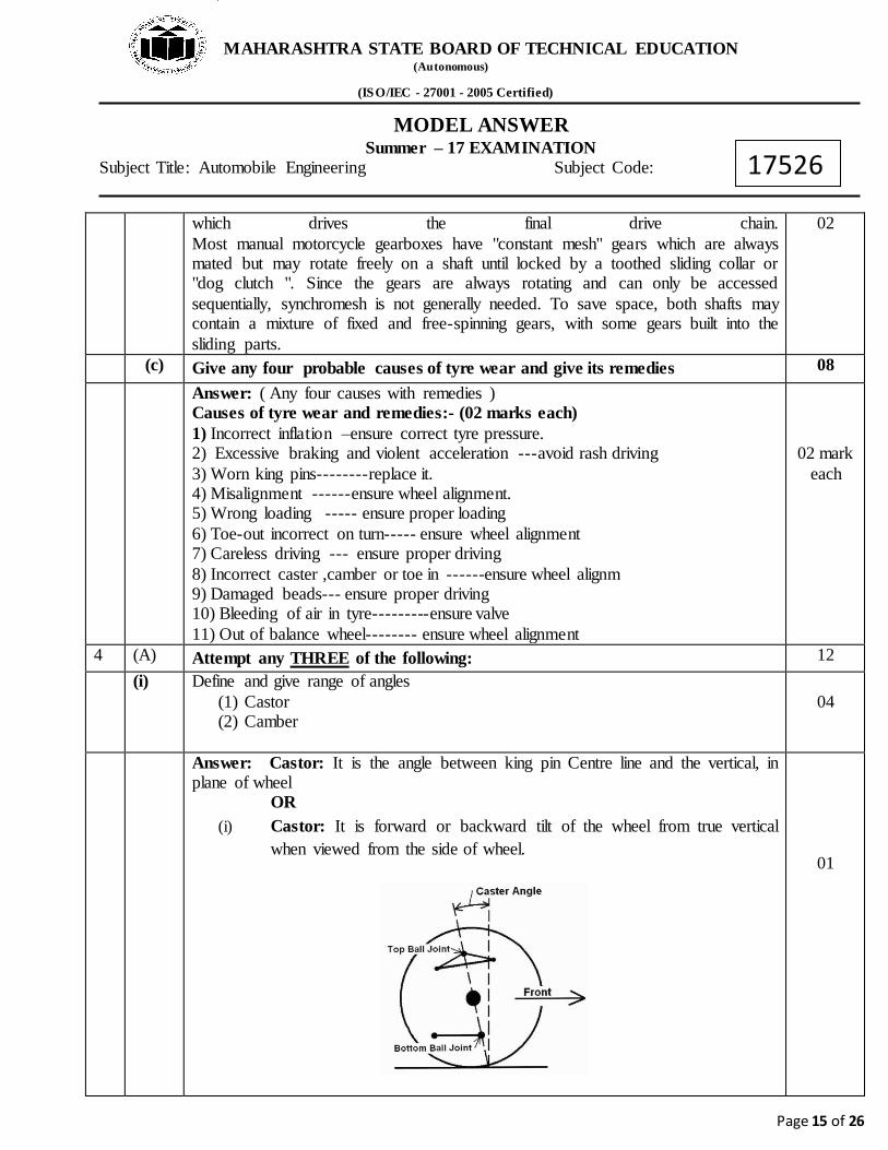
Answer: Castor: It is the angle between king pin Centre line and the vertical, in plane of wheel
OR (i) Castor: It is forward or backward tilt of the wheel from true vertical
when viewed from the side of wheel.
01
MAHARASHTRA STATE BOARD OF TECHNICAL EDUCATION (Autonomous) (ISO/IEC - 27001 - 2005 Certified)
MODEL ANSWER Summer – 17 EXAMINATION
Subject Title: Automobile Engineering Subject Code:
Page 16 of 26
17526
Range (Amount): About 3 degree of castor gives good results.
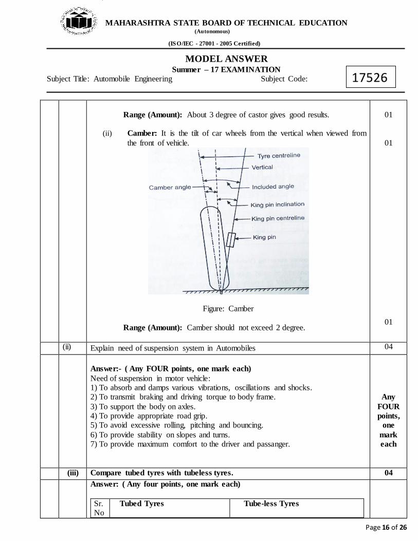
(ii) Camber: It is the tilt of car wheels from the vertical when viewed from the front of vehicle.
Figure: Camber Range (Amount): Camber should not exceed 2 degree.
01
01
01
(ii) Explain need of suspension system in Automobiles 04
Answer:- ( Any FOUR points, one mark each) Need of suspension in motor vehicle: 1) To absorb and damps various vibrations, oscillations and shocks. 2) To transmit braking and driving torque to body frame. 3) To support the body on axles. 4) To provide appropriate road grip. 5) To avoid excessive rolling, pitching and bouncing. 6) To provide stability on slopes and turns. 7) To provide maximum comfort to the driver and passanger.
Any FOUR points,
one mark each
(iii) Compare tubed tyres with tubeless tyres. 04 Answer: ( Any four points, one mark each)
Sr. No
Tubed Tyres Tube-less Tyres

MAHARASHTRA STATE BOARD OF TECHNICAL EDUCATION (Autonomous) (ISO/IEC - 27001 - 2005 Certified)
MODEL ANSWER Summer – 17 EXAMINATION
Subject Title: Automobile Engineering Subject Code:
Page 17 of 26
17526
1 Inside the tyre there is a separate tube
Inside the tyre Separate tube is not Provided instead the tyre from inside is lined with air retaining liner.
2 Tube contain air under pressure Whereas the air is present in between rim and the air retaining liner.
3 Air leakage is more as compare to tubeless tyre.
Slower leakage of air.
4 Poor Heat Decipation Better Heat Decipation
5 Tubed tyre can be used on wire spoked wheels
It is not possible to useTubelessTyre on wire spoked wheels.
6 More Unsprang weight Less Unsprang weight 7 In tube tyre the deflation is fast
damaging the tyre& tube.
If Punctured the tubeless tyre let the air out Slowly.
Any four points, one mark each
(iv) Describe with neat sketch the effect of (1) Under inflation (2) Over inflation
04
Answer: ( Effect of under inflation-1½, Effect of over inflation-1½, fig-01 marks) Effect of under inflation:
1) Uneven tread wear, more wear at the tyre sides. 2) Lack of directional stability 3) Increased rolling resistance leading to increased fuel consumption 4) The valve may be ripped out due to tyre sides.
Effect of over inflation:
1) Reduced tread contact area with the road surface. This result in rapid wear in the tread at the center.
2) Reduced tyre grip. 3) Reduced impact resistance. 4) Increased vibrations resulting in uncomfortable ride. 5) Increased stresses may causes tread separation & crack in the side walls.
1½ 1½ 01

MAHARASHTRA STATE BOARD OF TECHNICAL EDUCATION (Autonomous) (ISO/IEC - 27001 - 2005 Certified)
MODEL ANSWER Summer – 17 EXAMINATION
Subject Title: Automobile Engineering Subject Code:
Page 18 of 26
17526
Under inflation Over inflation
4 (B) Attempt any ONE of the following:
06
(i)
What are the components of hydraulic braking system? Explain construction and working of master cylinder
06
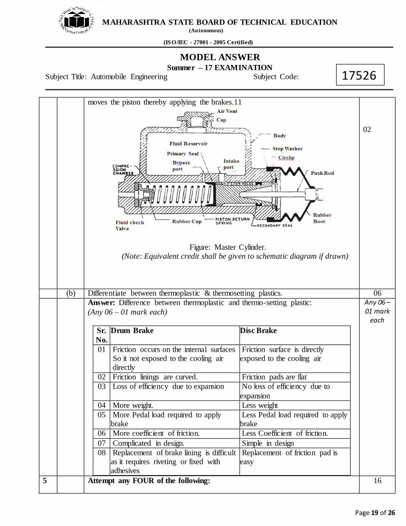
Answer: (Components of hydraulic braking system-01, construction-1½, working-1½, fig-02 marks) The components of hydraulic braking system are: (any four for 1 mark) 1) Brake pedal. 2) Master cylinder. 3) Oil reservoir. 4) Steel pipe lines, unions and flexible hoses 5) Wheel cylinder. 6) Brake shoe. 7) Disk or Drum brake. Construction: There are two main chambers viz. the fluid reservoir and compression chamber in which the piston operates. There are rubber seals on both ends of the piston in the compression chamber. The reduced diameter region of the piston is always surrounded by the fluid. A rubber boot covers the push rod end of the master cylinder to prevent the dust from entering inside. Towards the brake line side of the compression chamber, there is a fluid check valve with a rubber cup inside. Working: The push rod is operated with the foot brake pedal through linkage. As the pedal is pressed, push rod moves the piston to the left against the force of the spring till it covers the bypass port. Further movement f the push rod causes building up of pressure in the compression chamber. Finally, when sufficient pressure has built up, the inner rubber cup of the fluid check valve is deflected, forcing the fluid under pressure in the lines. This fluid enters the wheel cylinder or the caliper and
01
1½ 1½
MAHARASHTRA STATE BOARD OF TECHNICAL EDUCATION (Autonomous) (ISO/IEC - 27001 - 2005 Certified)
MODEL ANSWER Summer – 17 EXAMINATION
Subject Title: Automobile Engineering Subject Code:
Page 19 of 26
17526
moves the piston thereby applying the brakes.11
Figure: Master Cylinder. (Note: Equivalent credit shall be given to schematic diagram if drawn)
02
(b) Differentiate between thermoplastic & thermosetting plastics. 06 Answer: Difference between thermoplastic and thermo-setting plastic:
(Any 06 – 01 mark each)
Sr. No.
Drum Brake Disc Brake
01 Friction occurs on the internal surfaces So it not exposed to the cooling air directly
Friction surface is directly exposed to the cooling air
02 Friction linings are curved. Friction pads are flat 03 Loss of efficiency due to expansion No loss of efficiency due to
expansion 04 More weight. Less weight 05 More Pedal load required to apply
brake Less Pedal load required to apply brake
06 More coefficient of friction. Less Coefficient of friction. 07 Complicated in design. Simple in design 08 Replacement of brake lining is difficult
as it requires riveting or fixed with adhesives
Replacement of friction pad is easy
Any 06 – 01 mark
each
5 Attempt any FOUR of the following: 16

MAHARASHTRA STATE BOARD OF TECHNICAL EDUCATION (Autonomous) (ISO/IEC - 27001 - 2005 Certified)
MODEL ANSWER Summer – 17 EXAMINATION
Subject Title: Automobile Engineering Subject Code:
Page 20 of 26
17526
i) Describe construction of Macpherson suspension system with neat sketch. 04
Answer:
In this type of Suspension system only lower wishbone is used. A Strut containing shock absorber and the spring carries also the stub axle on which wheel is mounted. The Wishbone is hinged to the cross member. The wishbone positions the wheel as well as resists accelerating, braking and side forces. This type of suspension system is firstly used in Maruti 800. This type of Suspension with anti-roll bar as employed in Volkswagen jetta and passat car.
Neat
sketch 2 Marks
Descript
ion 2marks
ii) Explain function of Bendix drive in starter system. 04
Answer:
- It is a starting device. - Bendix drives are the inertia drives in which the starter motor pinion is made to engage or disengage with the toothed rings on the periphery of the engine flywheel.
- Drive head is keyed to the end of armature shaft. When current is passed to the starting motor (commutator and armature assembly), the armature shaft starts revolving at full speed.
- When pinion travels to the end of thread, it strikes the collar at left & forced to turn with the thread sleeve. This causes the flywheel & crankshaft to turn & crank the engine. - Immediately after starting the engine the unbalanced weight pinion returns to its initial position because speed of flywheel is more than speed of unbalanced weight pin
Explanation 2 Marks

MAHARASHTRA STATE BOARD OF TECHNICAL EDUCATION (Autonomous) (ISO/IEC - 27001 - 2005 Certified)
MODEL ANSWER Summer – 17 EXAMINATION
Subject Title: Automobile Engineering Subject Code:
Page 21 of 26
17526
Neat sketch 2 Marks
1 iii) State advantages of CDI ignition system. 04
Answer: (Any Four, 1 marks each)
1) It avoids contact breaker points and its maintenance 2) Better cold starting 3) Performance increases with speed 4) It provide constant voltage across spark plug 5) Secondary voltage remains constant with speed of engine. 6) Eliminate chances of misfiring.
1 Mark Each(To
tal 4 Marks)
iv) Write different color codes used in automobile wiring system. 04
Answer: Color code with function 1mark (any Four)

MAHARASHTRA STATE BOARD OF TECHNICAL EDUCATION (Autonomous) (ISO/IEC - 27001 - 2005 Certified)
MODEL ANSWER Summer – 17 EXAMINATION
Subject Title: Automobile Engineering Subject Code:
Page 22 of 26
17526
1 Mark Each(To
tal 4 Marks)
v) State and explain air conditioning parameters for human comfort. 04
Answer:
1) Temperature: Temperature is the most important factor which affects human comfort to a great extent. Most of the human being feels comfortable at a temperature 210C to 250C. Generally human being feels comfortable at relatively higher temperature in winter season and feels comfortable at relatively lower temperature in summer season. The comfort temperature of individual person depends on his body structure, eating habits, the area in which he is to make familiar to live. 2) Humidity: The control of humidity is not only necessary for human comfort but it is also important from point of view of efficiency of driver. For human comfort, relative humidity is kept within a range of 35% to 60%. 3) Purity of air: A person does not feel comfortable when breathing in contaminated air even if temperature and humidity is within comfortable range. Therefore, proper filtration, cleaning and purification of air is necessary to keep it free from dust, dirt and other impurities. The proper percentage of oxygen in air is necessary to be maintained for human comfort. Therefore, proper filtration system is provided in HVAC system in automobiles. 4) Air motion and circulation: Even if temperature, humidity and purity of air is satisfactory, certain amount of air motion is necessary for human comfort. We do not feel comfortable in dead or still air. It is therefore, necessary that there should be equi-distribution of air throughout the space to be air conditioned.
4 Marks
6 Attempt any TWO of the following: 16 i) State the function of battery in automobile. List the main components of lead
acid battery. Explain its construction with neat sketch. 08
Answer: Function of Battery, (2 point 2 marks) 1. Battery supplies the current for cranking motor and ignition system when the
MAHARASHTRA STATE BOARD OF TECHNICAL EDUCATION (Autonomous) (ISO/IEC - 27001 - 2005 Certified)
MODEL ANSWER Summer – 17 EXAMINATION
Subject Title: Automobile Engineering Subject Code:
Page 23 of 26
17526
engine is being cranked for starting.
2. When the vehicle is stationary battery supplies electricity for operating the various electrical devices.
3. It is the secondary source of electrical energy when vehicle is not operating and generator speed is insufficient to meet the full load requirement. The main Components of Battery are (four major comp. 1marks) 1. Container
2. Plates 3. Separators 4. Electrolyte
5. Cell Covers Construction of Battery (2 marks)
1. Container: - The container is made of acid resistance hard rubber or plastic. It is divided in to compartments. Each compartment form a cell of 2V. At the bottom of Container bridges are provided form space for sediment collection. This avoids the danger of short circuit.
2. Plates: - There are two types of battery plates positive & negative. Each plate is made of frame or Grid of an alloy of lead and antimony. The function of grid is to hold active material and carry the current. Active material in the positive plate grid is red lead (Pb3O4) and in the negative plate it is litharge (PbO).The negative plate group contain one plate more than the positive plate group.
3. Separators:-To avoid the direct contact & thus short circuiting of positive & -ve plates thin sheet of some Non-conducting material inserted between them called separator.
4. Cell Cover:- They are moulded from hard rubber . Each cell cover contains holes for positive and negative plate, a vent & filler opening. Vents are provided to escape the gases.
5. Electrolyte:- After assembling completely the battery is filled with electrolyte. It is a solution of Sulphuric acid contains approximately one part of Sulphuric acid & two part of water by volume. Specific gravity of Electrolyte is the measure of discharge of the battery. In the charge condition Sp.gr.is 1.290 where as in the discharge condition it is reduced to about 1.110.
2 Marks
1 Mark
2 Marks

MAHARASHTRA STATE BOARD OF TECHNICAL EDUCATION (Autonomous) (ISO/IEC - 27001 - 2005 Certified)
MODEL ANSWER Summer – 17 EXAMINATION
Subject Title: Automobile Engineering Subject Code:
Page 24 of 26
17526
3 Marks
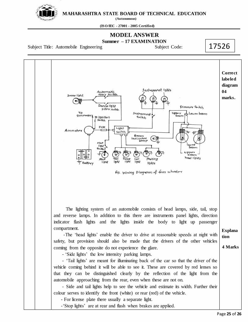
ii) Explain typical wiring diagram of four wheeler automobile with neat sketch.
MAHARASHTRA STATE BOARD OF TECHNICAL EDUCATION (Autonomous) (ISO/IEC - 27001 - 2005 Certified)
MODEL ANSWER Summer – 17 EXAMINATION
Subject Title: Automobile Engineering Subject Code:
Page 25 of 26
17526
The lighting system of an automobile consists of head lamps, side, tail, stop and reverse lamps. In addition to this there are instruments panel lights, direction indicator flash lights and the lights inside the body to light up passenger compartment. -The ‘head lights’ enable the driver to drive at reasonable speeds at night with
safety, but provision should also be made that the drivers of the other vehicles coming from the opposite do not experience the glare. - ‘Side lights’ the low intensity parking lamps. - ‘Tail lights’ are meant for illuminating back of the car so that the driver of the
vehicle coming behind it will be able to see it. These are covered by red lenses so that they can be distinguished clearly by the reflection of the light from the automobile approaching from the rear, even when these are not on. - Side and tail lights help to see the vehicle and estimate its width. Further their colour serves to identify the front (white) or rear (red) of the vehicle. - For license plate there usually a separate light. -‘Stop lights’ are at rear and flash when brakes are applied.
Correct labeled diagram
04 marks.
Explanation
4 Marks
MAHARASHTRA STATE BOARD OF TECHNICAL EDUCATION (Autonomous) (ISO/IEC - 27001 - 2005 Certified)
MODEL ANSWER Summer – 17 EXAMINATION
Subject Title: Automobile Engineering Subject Code:
Page 26 of 26
17526
- The ‘reverse light’ is also incorporated at the rear. - Trafficators or the ‘flash lights’ are also used to indicate the direction in which the vehicle is about to turn. The required electric current in the automobile flows from the battery to the various lights, parts and returns back to the battery.
iii) Write any eight precautions to be taken while using air conditioning system in automobiles. ( Eight Points)
08
Answer: -1) Operate the air conditioner periodically or at least once a week to keep the internal parts lubricated as well as prevent the hoses from hardening. - 2) Do not switch ON the A.C. at high speeds which may result in the ceasing of compressor. - 3) Do not stick anything into the air outlet or the air inlet. As it dangerous and it can cause injury or damage. - 4) Avoid exposing a body directly to a continuous cool air flow for long periods- It is not good for health. - 5) Avoid placing any obstacles near the inlet or outlet- if inlet or outlet is blocked it may causes damage to the unit. - 6) Do not run or stop the unit frequently. If run or stop the unit more than 4-5 times an hour, it may cause damage to the unit. - 7) The air filter should be cleared at least once every two weeks. - 8) When the unit is cleaned, set the selector switch at off position. - 9) Never operate A.C. with heater on. - 10) Do not charge the refrigerant in the A.C. system before flushing.
1 Mark for each correct point
(Total 8marks)