stylus system changer set-up procedures for zeiss cmms zeiss... · section 5: st3 stylus changer...
TRANSCRIPT

[Type text] [Type text] [Type text]
Tool Changer Page 1 of 23
Stylus System Changer Set-up Procedures for Zeiss CMMs
Table of Contents
SECTION 1: SETTING STYLUS SYSTEM CHANGER PARAMETERS ........................................... 3
SECTION 2: STYLUS SYSTEM CHANGER SETUP FOR SCANNING CMMS WITH VAST, OR
VAST-XT SCANNING HEADS .................................................................................................................. 4
ADDING A HOLDER ........................................................................................... SECTION 2, STEP 6
SECTION 3: RST ADAPTER PLATE CHANGER SETUP FOR ROTATING HEAD ....................... 6
SECTION 4: MCR20 STYLUS CHANGER SETUP FOR ROTATING HEAD ..................................11
SECTION 5: ST3 STYLUS CHANGER SETUP FOR TOUCH-SENSOR CMMS ..............................14
SECTION 6: STYLUS SYSTEM CHANGER SETUP FOR VAST XXT..............................................16
SECTION 7: DEFINING APPROACH PARAMETERS ........................................................................19
[Type text] [Type text] [Type text]
Tool Changer Page 2 of 23
Using this manual:
All users follow Section 1: Setting Stylus System Changer Parameters.
After setting the changer parameters, follow the procedure specific to the probe head style of your CMM.
Define Approach Parameters in Section 7.
[Type text] [Type text] [Type text]
Tool Changer Page 3 of 23
Section 1: Setting Stylus System Changer Parameters
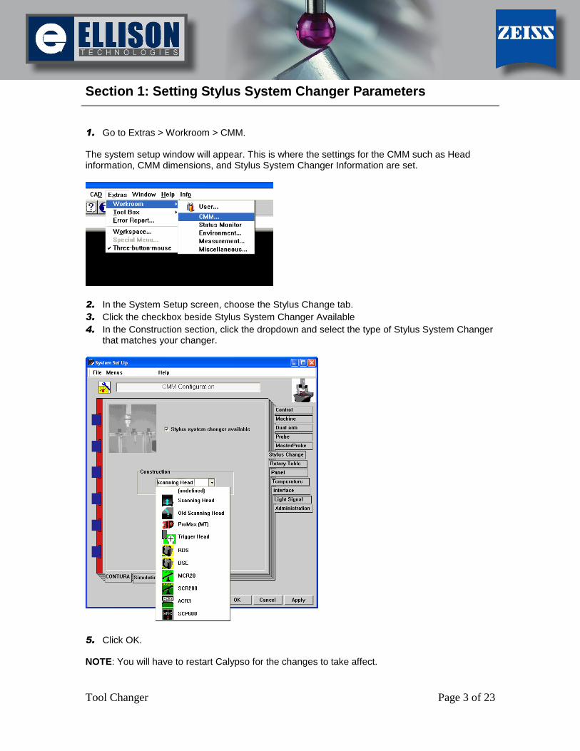
1. Go to Extras > Workroom > CMM. The system setup window will appear. This is where the settings for the CMM such as Head information, CMM dimensions, and Stylus System Changer Information are set.
2. In the System Setup screen, choose the Stylus Change tab.
3. Click the checkbox beside Stylus System Changer Available
4. In the Construction section, click the dropdown and select the type of Stylus System Changer that matches your changer.
5. Click OK. NOTE: You will have to restart Calypso for the changes to take affect.
[Type text] [Type text] [Type text]
Tool Changer Page 4 of 23
Section 2: Stylus System Changer Setup for Scanning CMMs with Vast, or Vast-XT Scanning Heads.
1. Affix the Stylus System Changer to the CMM table using the bolts accompanying the changer in the desired orientation. The most common orientation is on the backside of the CMM facing the front, however the changer may be installed in any axis direction: X, -X, Y, or –Y.
2. Align the changer to the machine axis. This is done by one of the following:
A. Drive the stylus system using the joysticks along one of the machine axes, making adjustments to the changer as needed so that when adjustments are complete, the stylus system drives parallel to the changer.
B. Take a manual probing point on the front face at either end of the changer and compare the positions in X and Y. Make adjustments until the changer has minimal deviation in the machine axis direction (X or Y).
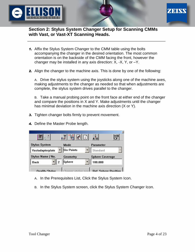
3. Tighten changer bolts firmly to prevent movement. 4. Define the Master Probe length.
A. In the Prerequisites List, Click the Stylus System Icon.
B. In the Stylus System screen, click the Stylus System Changer Icon.

[Type text] [Type text] [Type text]
Tool Changer Page 5 of 23
C. Click the Length of Master Probe button.
D. Calypso will prompt you to probe the adapter plate (the plate through which the Master Probe is attached to the probe head) on the top of the changer bay and then probe the same point with the ruby stylus tip. The Master Probe Length will then be displayed.
1. In the Changer dropdown, select Approach Parameters and change the
approach direction to the correct changer orientation.
2. To add a holder, click the Edit dropdown and select Add Holder. Names may
be given to each holder position created. Up to 15 holder positions may be created.
4.2 users: Define the type of Holder; in this case choose MT. 3. Click on the first holder (holder position will turn green when selected) and
click the Changer dropdown. Choose Define Holder Location. 4. Drive the Master Probe to the changer bay that is to be defined. Position the
Master Probe just above the spherical pocket located on the right side of the bay. Follow the user prompts in Calypso to define the holder location. The

[Type text] [Type text] [Type text]
Tool Changer Page 6 of 23
holder is located by a self-centering point taken by the Master Probe in the holder pocket. Repeat steps 7 and 8 for all holder locations.
5. In the Stylus System Changer screen, select a holder position and, from the
Changer dropdown, select Set Stylus System to Holder. From the list, choose a stylus system for each holder position.
[Type text] [Type text] [Type text]
Tool Changer Page 7 of 23
Section 3: RST Adapter Plate Changer Setup for Rotating Head CMMs.
Note: Determining RDS-Geometry must only be done if the stylus system
changer is being installed for the first time. The master probe must be qualified in all 5 positions before the RDS stylus system changer can be defined. 1. Perform a manual stylus system change to install the Master Probe and find
the Reference Sphere Position. After the reference sphere has been located, qualify the preset stylus positions.
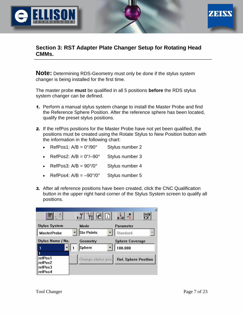
2. If the refPos positions for the Master Probe have not yet been qualified, the
positions must be created using the Rotate Stylus to New Position button with the information in the following chart:
RefPos1: A/B = 0°/90° Stylus number 2
RefPos2: A/B = 0°/–90° Stylus number 3
RefPos3: A/B = 90°/0° Stylus number 4
RefPos4: A/B = –90°/0° Stylus number 5
3. After all reference positions have been created, click the CNC Qualification
button in the upper right hand corner of the Stylus System screen to qualify all positions.

[Type text] [Type text] [Type text]
Tool Changer Page 8 of 23
4. Open the Automatic Stylus System Changer and click the Determine RDS-Geometry button in the upper right hand corner.
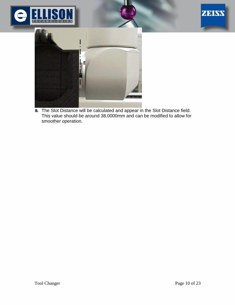
5. With the RDS head articulated to a qualified position, align the outer slot surface of the adapter plate with the plane of the stylus system changer. SEE PICTURE BELOW:
[Type text] [Type text] [Type text]
Tool Changer Page 9 of 23
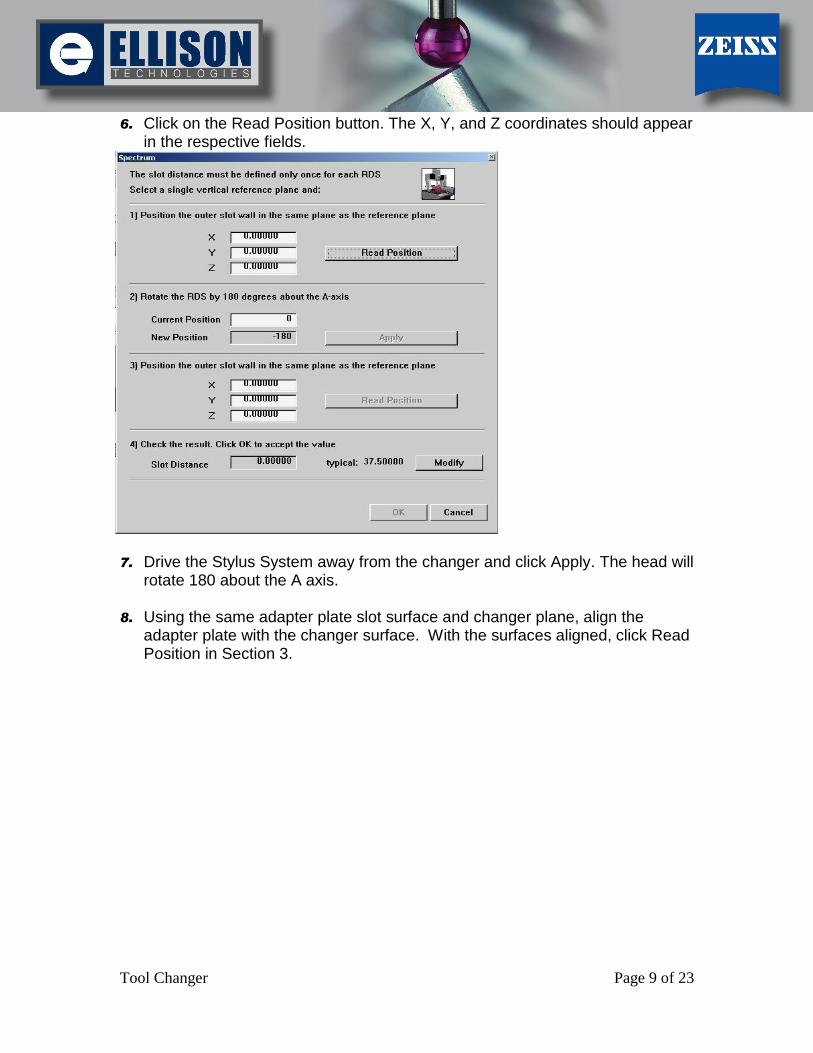
6. Click on the Read Position button. The X, Y, and Z coordinates should appear in the respective fields.
7. Drive the Stylus System away from the changer and click Apply. The head will
rotate 180 about the A axis. 8. Using the same adapter plate slot surface and changer plane, align the
adapter plate with the changer surface. With the surfaces aligned, click Read Position in Section 3.
[Type text] [Type text] [Type text]
Tool Changer Page 10 of 23
9. The Slot Distance will be calculated and appear in the Slot Distance field.
This value should be around 38.0000mm and can be modified to allow for smoother operation.
[Type text] [Type text] [Type text]
Tool Changer Page 11 of 23
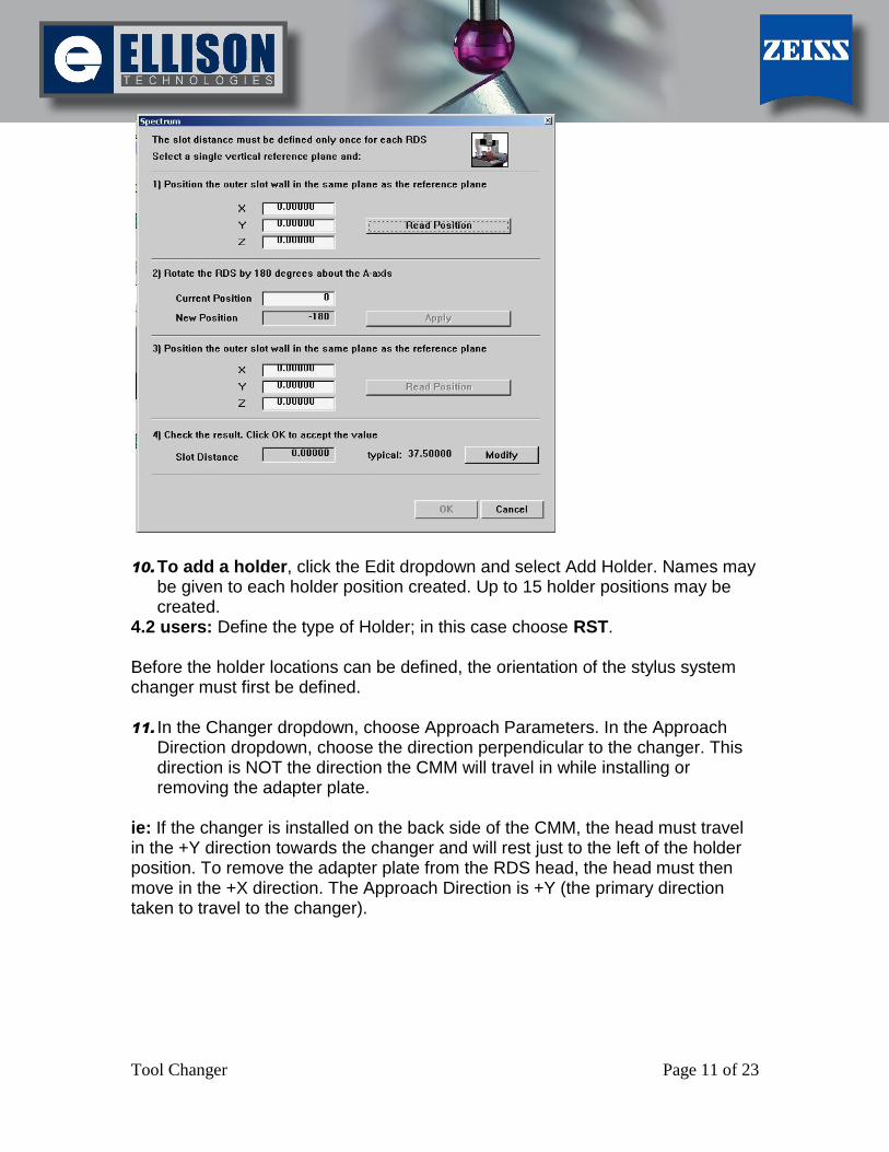
10. To add a holder, click the Edit dropdown and select Add Holder. Names may
be given to each holder position created. Up to 15 holder positions may be created.
4.2 users: Define the type of Holder; in this case choose RST. Before the holder locations can be defined, the orientation of the stylus system changer must first be defined. 11. In the Changer dropdown, choose Approach Parameters. In the Approach
Direction dropdown, choose the direction perpendicular to the changer. This direction is NOT the direction the CMM will travel in while installing or removing the adapter plate.
ie: If the changer is installed on the back side of the CMM, the head must travel in the +Y direction towards the changer and will rest just to the left of the holder position. To remove the adapter plate from the RDS head, the head must then move in the +X direction. The Approach Direction is +Y (the primary direction taken to travel to the changer).

[Type text] [Type text] [Type text]
Tool Changer Page 12 of 23
12. To define the holder location, choose the holder to be located and select Define Holder Location from the Changer dropdown.
NOTE: The RDS head must be rotated to the position needed to enter the holder (the roller should contact the RDS head on the side opposite the adapter plate). 13. Follow the prompts provided by Calypso to locate the holder position. The first
probing point will be taken manually on the top of the raised cube on the back corner of the holder.
Figure 1: Location of raised cube on holder
Following the manual probing point, the Master Probe will finish locating the raised cube automatically.
[Type text] [Type text] [Type text]
Tool Changer Page 13 of 23
14. Once the position of the holder has been defined, verify the position by storing the Master Probe into the newly-defined holder. In the Stylus System Changer screen, select the defined holder (the holder will turn green when selected), and in the Changer dropdown select Remove Stylus System.
BE CAREFUL! Load the probe into the holder slowly for the first time,
making sure the alignment of the adapter plate to the holder is correct. If the alignment is incorrect, turn the speed control knob on the joystick box all the way down to stop the CMM motion. Navigate to the Stoplight and click the red light followed by the green light. This will allow the user control of the CMM again. 15. Repeat Steps 9 through 11 until all holders have been defined. 16. In the Stylus System Changer screen, select a holder position, click the
Changer dropdown, and select Set Stylus System to Holder. Choose the stylus system for each holder.

[Type text] [Type text] [Type text]
Tool Changer Page 14 of 23
Section 4: MCR20 Stylus Changer Setup for Rotating Head CMMs.
To define the holder positions of the MCR20:
1. Open the covers of the MCR20.
2. In the Prerequisites List, click the Stylus System Icon.
3. Perform a Stylus System Change to use the Master Probe.
Important
Always use the PS2R stylus system without extension (2 mm head, 20 mm shaft) for the qualification procedure.
4. In the Stylus System screen, click the Automatic Stylus System Change icon. The Automatic Stylus System Change dialog box appears on the screen.
5. To add a holder, click the Edit dropdown and select Add Holder. Names may be given to each holder position created. Up to 15 holder positions may be created.
4.2 users: Define the type of Holder; in this case choose MCR20.
6. In the Automatic Stylus System Change screen, select a holder position (the holder position will turn green when selected).
[Type text] [Type text] [Type text]
Tool Changer Page 15 of 23
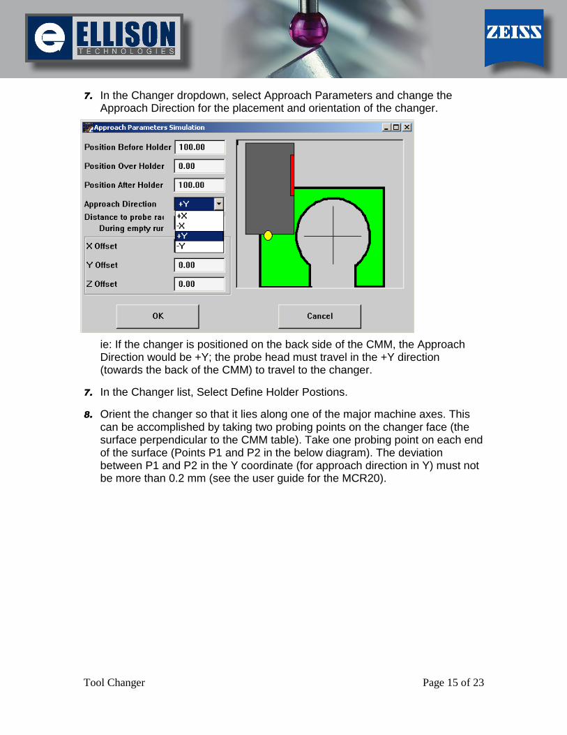
7. In the Changer dropdown, select Approach Parameters and change the Approach Direction for the placement and orientation of the changer.
ie: If the changer is positioned on the back side of the CMM, the Approach Direction would be +Y; the probe head must travel in the +Y direction (towards the back of the CMM) to travel to the changer.
7. In the Changer list, Select Define Holder Postions.
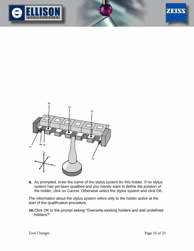
8. Orient the changer so that it lies along one of the major machine axes. This can be accomplished by taking two probing points on the changer face (the surface perpendicular to the CMM table). Take one probing point on each end of the surface (Points P1 and P2 in the below diagram). The deviation between P1 and P2 in the Y coordinate (for approach direction in Y) must not be more than 0.2 mm (see the user guide for the MCR20).
[Type text] [Type text] [Type text]
Tool Changer Page 16 of 23
9. As prompted, enter the name of the stylus system for this holder. If no stylus system has yet been qualified and you merely want to define the position of the holder, click on Cancel. Otherwise select the stylus system and click OK.
The information about the stylus system refers only to the holder active at the start of the qualification procedure.
10. Click OK to the prompt asking “Overwrite existing holders and add undefined holders?”

[Type text] [Type text] [Type text]
Tool Changer Page 17 of 23
If the MCR20 stylus system changer is selected, only MCR20 holders are displayed. Holders of other types for this machine configuration are deleted.
Important!
Always use Reduced Speed (Speed Control Knob on the joystick box) for movement, as there could be a risk of collision.
11. When prompted, probe point 1 (P1) on the left end face of the MCR20.
12. Calypso will continue the changer position definition automatically. When the qualification is completed, all six holder positions of the MCR20 are labeled from "1" to "6".
13. Close the covers when prompted.
The covers must be closed so the magnets mounted in them can function correctly by keep the switching contact closed during stylus system changes.
14. Click OK.
The window will be closed.
[Type text] [Type text] [Type text]
Tool Changer Page 18 of 23
Section 5: ST3 Stylus Changer Setup for Touch-Sensor
CMMs
1. Install the Stylus System Changer. Using the bolts that came with the changer, attach the changer to the CMM table in the appropriate orientation. The front face of the changer can be in one of several directions: –Y, +Y, -X, or +X. The –Y direction is used most often.
2. Perform a stylus system change to install the Master Probe. 3. Align the changer to a major machine axis. This may be accomplished by one
of the following:
C. Drive the stylus system using the joysticks along one of the machine axes, making adjustments to the changer as needed. When adjustments are complete, the stylus system should drive parallel to the changer.
D. Take a manual probing point on either side of the changer and make adjustments until the changer is aligned with machine axis.
3. Tighten changer bolts firmly to prevent movement. 4. Define the Master Probe length.
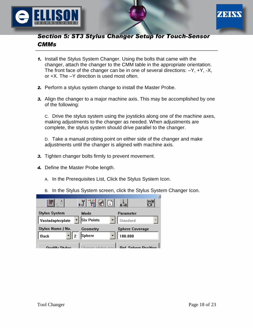
A. In the Prerequisites List, Click the Stylus System Icon.
B. In the Stylus System screen, click the Stylus System Changer Icon.
[Type text] [Type text] [Type text]
Tool Changer Page 19 of 23
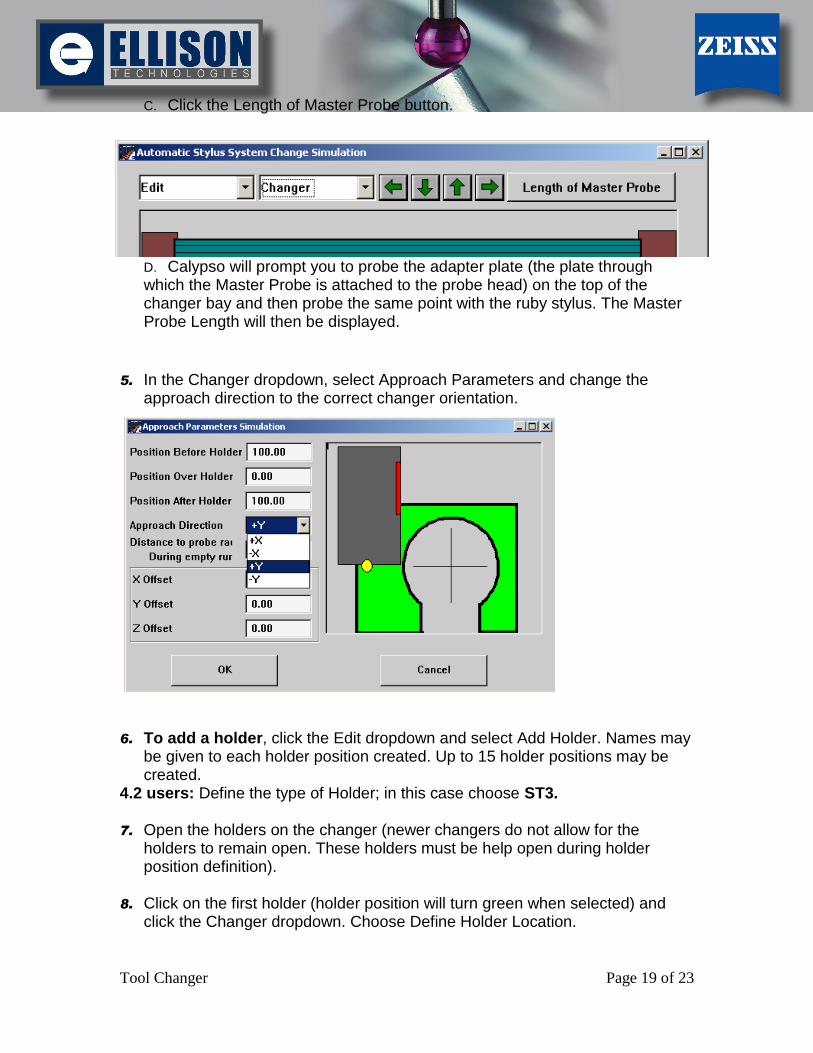
C. Click the Length of Master Probe button.
D. Calypso will prompt you to probe the adapter plate (the plate through which the Master Probe is attached to the probe head) on the top of the changer bay and then probe the same point with the ruby stylus. The Master Probe Length will then be displayed.
5. In the Changer dropdown, select Approach Parameters and change the
approach direction to the correct changer orientation.
6. To add a holder, click the Edit dropdown and select Add Holder. Names may
be given to each holder position created. Up to 15 holder positions may be created.
4.2 users: Define the type of Holder; in this case choose ST3. 7. Open the holders on the changer (newer changers do not allow for the
holders to remain open. These holders must be help open during holder position definition).
8. Click on the first holder (holder position will turn green when selected) and
click the Changer dropdown. Choose Define Holder Location.
[Type text] [Type text] [Type text]
Tool Changer Page 20 of 23
9. Calypso will prompt for the Master Probe to be centered in the holder. Using the joysticks, drive the stylus system so that it is centered in the holder and slightly below the top (approximately 5mm or 3/16”) of the first holder. Repeat steps 12 and 13 until all holders are defined.
10. In the Stylus System Changer screen, select a holder position and, from the
Changer dropdown, select Set Stylus System to Holder. From the list, choose a stylus system for each holder position.
[Type text] [Type text] [Type text]
Tool Changer Page 21 of 23
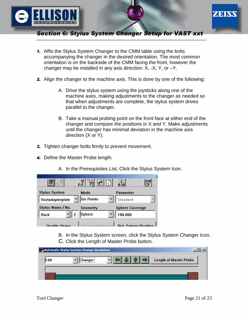
Section 6: Stylus System Changer Setup for VAST xxt
1. Affix the Stylus System Changer to the CMM table using the bolts accompanying the changer in the desired orientation. The most common orientation is on the backside of the CMM facing the front, however the changer may be installed in any axis direction: X, -X, Y, or –Y.
2. Align the changer to the machine axis. This is done by one of the following:
A. Drive the stylus system using the joysticks along one of the machine axes, making adjustments to the changer as needed so that when adjustments are complete, the stylus system drives parallel to the changer.
B. Take a manual probing point on the front face at either end of the
changer and compare the positions in X and Y. Make adjustments until the changer has minimal deviation in the machine axis direction (X or Y).
3. Tighten changer bolts firmly to prevent movement. 4. Define the Master Probe length.
A. In the Prerequisites List, Click the Stylus System Icon.
B. In the Stylus System screen, click the Stylus System Changer Icon.
C. Click the Length of Master Probe button.
[Type text] [Type text] [Type text]
Tool Changer Page 22 of 23
5. Calypso will prompt you to probe the adapter plate (the plate through which the Master Probe is attached to the probe head) on the top of the changer bay and then probe the same point with the ruby stylus tip. The Master Probe Length will then be displayed.
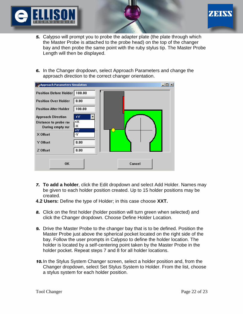
6. In the Changer dropdown, select Approach Parameters and change the
approach direction to the correct changer orientation.
7. To add a holder, click the Edit dropdown and select Add Holder. Names may
be given to each holder position created. Up to 15 holder positions may be created.
4.2 Users: Define the type of Holder; in this case choose XXT. 8. Click on the first holder (holder position will turn green when selected) and
click the Changer dropdown. Choose Define Holder Location. 9. Drive the Master Probe to the changer bay that is to be defined. Position the
Master Probe just above the spherical pocket located on the right side of the bay. Follow the user prompts in Calypso to define the holder location. The holder is located by a self-centering point taken by the Master Probe in the holder pocket. Repeat steps 7 and 8 for all holder locations.
10. In the Stylus System Changer screen, select a holder position and, from the
Changer dropdown, select Set Stylus System to Holder. From the list, choose a stylus system for each holder position.

[Type text] [Type text] [Type text]
Tool Changer Page 23 of 23
Section 7: Defining Approach Parameters
In the Changer dropdown, select Define Approach Parameters.
Adjust the position before, over, and after holder so stylus system will clear the changer during stylus system changes. NOTE: This must be done for each holder. You may have to make changes to holder approach parameters for various stylus systems. If you find the need to move a stylus system to another changer holder, you will have to change the approach parameters for the new stylus location. The approach parameters apply to the HOLDER not the Stylus System!